
PROCEEDINGS OF THE EURO-C 1998 CONFERENCE ON COMPUTATIONAL MODELLING OFCONCRETESTRUCTURES/BADGASTEIN/AUSTRIA/31 MARCH- 3 APRIL 1998
Computational Modelling of Concrete Structures Edited by
Rene de Borst Faculty of Civil Engineering, Delft University of Technology, Netherlands
Nenad Bicanic Department of Civil Engineering, University of Glasgow, UK
Herbert Mang & Gunther Meschke Institute for Strength 0/ Materials, Technical University a/Vienna, Austria
OFFPRINT
A.A. BALKEMA/ROTTERDAM/BROOKFIELDI 1998

Computational Modelling of Concrete Structures, de Borst, BiCanic, Mang & Meschke (eds) © 1998 Balkema, Rotterdam, ISBN 90 5410 946 7
Modelling of compressive strain softening, fracture and size effect in concrete
Zdenek P. Baiant Northwestern University, Evanston, Ill., USA
ABSTRACT: It is by now well established that tensile failure of quasibrittle materials such as concrete exhibits a significant nonstatistical size effect on the nominal strength of structure, but it is still widely believed that compression failure does not. Recent researches are showing this belief to be untrue. The present paper reviews recent research results on this problem and presents a simplified quasi-LEFM analysis of the size effect in compression. The basic characteristics and mechanisms of compression failure are reviewed and the distinction between local and global mechanisms is emphasized. The maximum load is considered to be reached because the material develops axial splitting cracks and undergoes internal buckling (microbuckling) in a localized band that propagates in either axial or lateral direction (the latter appearing after reduction of load to zero as a 'shear' failure). The fully fractured and microbuckled tail of crack band may transmit a finite residual stress. J-integral analysis of the energy release is used to obtain the approximate size effect law for compression for a simple specimen shape, and equivalent LEFM (linear elastic fracture mechanics) approximation is then used to derive size effect formulae that take also into account the effect of structure geometry (shape). The cases of failure after long stable growth of crack band and at crack band initiation are distinguished. Experimental results on size effect in reinforced concrete columns and, for the purpose of analogy, also in carbon-PEEK laminates, are discussed. Finally, one practical application in which the truss model for diagonal shear failure is extended to size effect is presented and some implications for finite element analysis are discussed.
1. INTRODUCTION
The size effect on the nominal strength of structures made of quasibrittle materials such as concrete, rock, ice, ceramics and composites is not restricted to tensile fracture. For such materials, compression fracture, too, exhibits size effect (e.g. van Mier, 1986; Gonnermann, 1925; Blanks and McNamara, 1935; Marti, 1989; Jishan and Xixi, 1990; Bazant and Chen 1997; Bazant et al. 1998). The compression fracture, however, is more complex and less understood. Yet it often is the more important and dangerous mode of failure, which is highly brittle, lacking ductility.
Same as brittle tensile failure, compression failure, in general, cannot be considered to be controlled by a material strength criterion, as implied in nearly all practical applications up to now. Rather, as suggested or implied by some researchers (e.g. Ingraffea, 1977; Bazant et al. 1993; Bieniawski, 1974; Hoek and Bieniawski, 1965; Cotterell,
1972; Paul, 1968) and described mathematically in Baiant (1994a) and Baiant and Xiang (1997), the compression failure in quasibrittle materials is caused predominantly by the release of stored energy from the structure, which in turn engenders localization and size effect. This aspect is similar to fracture mechanics of tensile cracks. A size effect must be expected, in general, whenever material failure involves post-peak softening and lacks ductility. The size effect is the most important practical consequence of fracture phenomena, and observations of the size effect are an effective way to calibrate the parameters of a fracture model.
Summarizing and reviewing several recent studies at Northwestern University (Baiant and Xiang 1997, Bazant and Chen 1997, Bazant et al. 1998), the present conference paper will attempt to explain the compression size effect in a simple and plausible manner, outline a simplified model for the lateral propagation of a band of axial splitting cracks, sketch a simplified analysis of the size effect
249
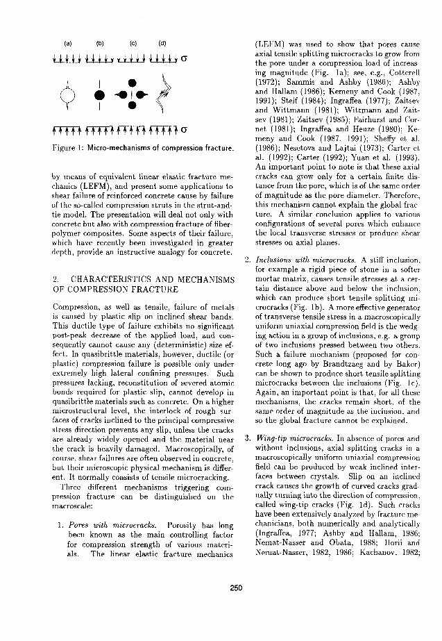
(a) (b) (c) (d)
rrm rrm rrm f1TIl cr
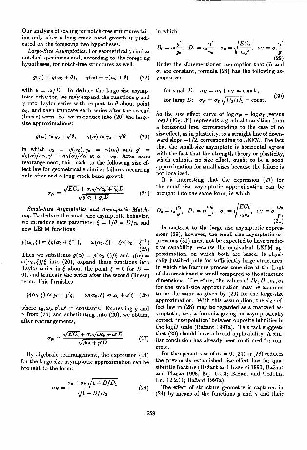
Figure 1: Micro-mechanisms of compression fracture.
by means of equivalent linear elastic fracture mechanics (LEFM), and present some applications to shear failure of reinforced concrete cause by failure of the so-called compression struts in the strut-andtie model. The presentation will deal not only with concrete but also with compression fracture of fiberpolymer composites. Some aspects of their failure, which have recently been investigated in greater depth, provide an instructive analogy for concrete.
2. CHARACTERISTICS AND MECHANISMS OF COMPRESSION FRACTURE
Compression, as well as tensile, failure of metals is caused by plastic slip on inclined shear bands. This ductile type of failure exhibits no significant post-peak decrease of the applied load, and consequently cannot cause any (deterministic) size effect. In quasibrittle materials, however, ductile (or plastic) compression failure is possible only under extremely high lateral confining pressures. Such pressures lacking, reconstitution of severed atomic bonds required for plastic slip, cannot develop in quasi brittle materials such as concrete. On a higher microstructural level, the interlock of rough surfaces of cracks inclined to the principal compressive stress direction prevents any slip, unless the cracks are already widely opened and the material near the crack is heavily damaged. Macroscopically, of course, shear failures are often observed in concrete, but their microscopic physical mechanism is different. It normally consists of tensile microcracking.
Three different mechanisms triggering compression fracture can be distinguished on the macroscale:
1. Pores with microcracks. Porosity has long been known as the main controlling factor for compression strength of various materials. The linear elastic fracture mechanics
250
(LEFM) was used to show that pores cause axial tensile splitting microcracks to grow from the pore under a compression load of increasing magnitude (Fig. la); see, e.g., Cotterell (1972); Sammis and Ashby (1986); Ashby and Hallam (1986); Kemeny and Cook (1987, 1991); Steif (1984); Ingraffea (1977); Zaitsev and Wittmann (1981); Wittmann and Zaitsev (1981); Zaitsev (1985); Fairhurst and Cornet (1981); Ingraffea and Heuze (1980); Kemeny and Cook (1987, 1991); Sheffy et al. (1986); Nesetova and Lajtai (1973); Carter et al. (1992); Carter (1992); Yuan et al. (1993). An important point to note is that these axial cracks can grow only for a certain finite distance from the pore, which is of the same order of magnitude as the pore diameter. Therefore, this mechanism cannot explain the global fracture. A similar conclusion applies to various configurations of several pores which enhance the local transverse stresses or produce shear stresses on axial planes.
2. Inclusions with microcracks. A stiff inclusion, for example a rigid piece of stone in a softer mortar matrix, causes tensile stresses at a certain distance above and below the inclusion, which can produce short tensile splitting microcracks (Fig. 1 b). A more effective generator of transverse tensile stress in a macroscopically uniform uniaxial compression field is the wedging action in a group of inclusions, e.g. a group of two inclusions pressed between two others. Such a failure mechanism (proposed for concrete long ago by Brandtzaeg and by Baker) can be shown to produce short tensile splitting microcracks between the inclusions (Fig. lc). Again, an important point is that, for all these mechanisms, the cracks remain short, of the same order of magnitude as the inclusion, and so the global fracture cannot be explained.
3. Wing-tip microcracks. In absence of pores and without inclusions, axial splitting cracks in a macroscopically uniform uniaxial compression field can be produced by weak inclined interfacfls between crystals. Slip on an inclined crack causes the growth of curved cracks gradually turning into the direction of compression, called wing-tip cracks (Fig. Id). Such cracks have been extensively analyzed by fracture mechanicians, both numerically and analytically (Ingraffea, 1977; Ashby and Hallam, 1986; Nemat-Nasser and Obata, 1988; Horii and Nemat-Nasser, 1982, 1986; Kachanov, 1982;

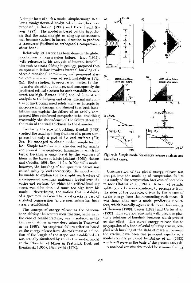
(a) (b) (c) (d)
~ " ~ ,..........., 11111111111 j
111101lff1
f f t t f ft f f f It tttttltttttt
(e) (f) (g) (h)
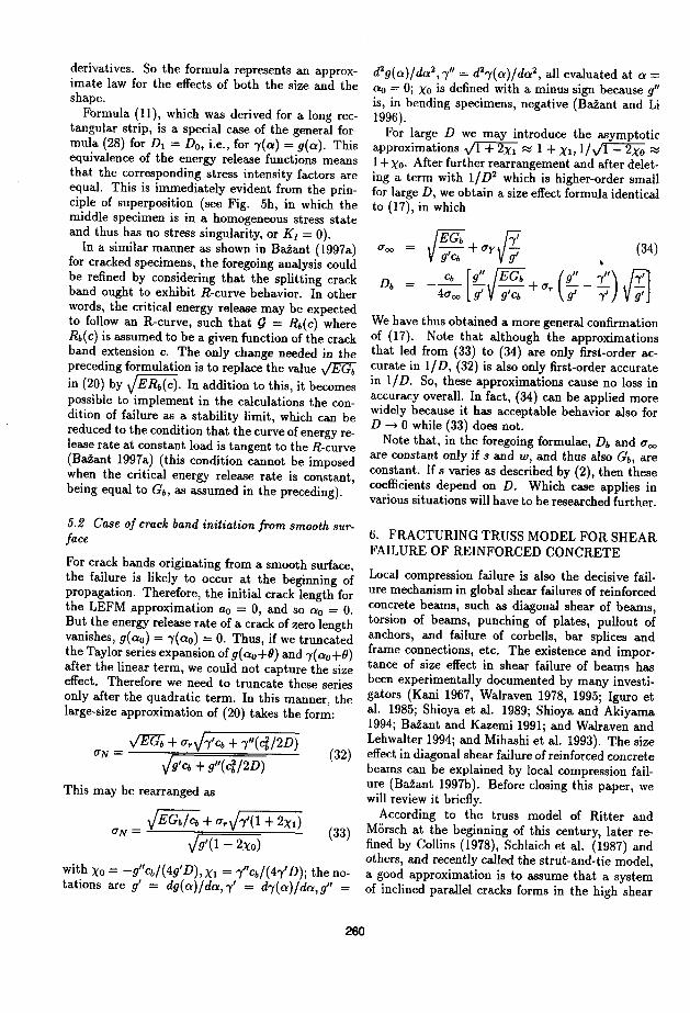
Figure 2: Macro-mechanisms of compression fracture.
Lehner and Kachanov, 1996; Batto and Schulson, 1993; and Schul son and Nickolayev, 1995), and curved crack growth under compression has been clarified (Cotterell and Rice, 1980). A fully realistic analysis of wing-tip cracks would have to be three-dimensional, which has apparently not yet been accomplished. Important to note, the length of the wing-tip cracks is again of the same order of magnitude as the length of the inclined slipping crack, and so the global fracture cannot be modeled.
Mathematical modeling of failure of quasi brittie structures under compression requires that the global mechanism of compression fracture be understood. This mechanism is more complex than the mechanism of tensile fracture.
One complicating feature is that fracture in compression is inherently a triaxial phenomenon, influenced by the triaxial stress state at the fracture front. By contrast, as documented by the success of the cohesive (fictitious) crack model of Hillerborg, tensile fracture is describable as a uniaxial phenomenon (in terms of the crack-bridging cohesive normal stress only).
Among the global failure mechanisms, two kinds may be distinguished: those that cause a global energy release with size effect, and those that do not. A mechanism of the first kind is represented by the propagation of a continuous macroscopic splitting crack (Fig. 2b). Such failure is known to occur in small laboratory test specimens, especially when the ends are sliding with negligible friction.
While a transverse tensile crack causes a change
251
in the macroscopic stress field (Fig. 2a), an axial splitting macro-crack does not (Fig. 2b), and consequently does not cause any global release of energy. The energy to form the axial splitting crack and propagate it must come from some local mechanism, such as the release of stored energy from the fracture process zone (and must be calculated from its triaxial constitutive relation; Bazant and Ozbolt, 1992). Because of the absence of a global energy release, compression failure caused by an axial splitting macro-crack cannot cause any size effect. This appears to be confirmed by the numerical results of BaZant and Ozbolt (1992) and Droz and BaZant (1989), and does not conflict with 'experimental evidence.
When the load required to drive the local mechanism of axial splitting crack propagation is higher than that required to drive a global mechanism of failure due to energy release, the global mechanism will occur. As we will see, the global mechanism is accompanied by size effect (Fig. 3h), and so it will prevail for sufficiently large sizes.
The mechanism of global energy release must obviously involve some sort of transverse propagation of a cracking band (or strain-softening damage band). Such a band may logically be supposed to consist of densely distributed axial splitting microcracks. The weakening of the material by microcracks may be expected to cause internal buckling (Fig. 3d,g,h).
Although mathematical modeling of the aforementioned mechanisms in which cracks are engendered by pores, inclusions and slips on inclined interfaces has led to important results, it must be recognized that these results are limited to the microscopic initiation of compression fracture. They do not describe the global, macroscopic compression failure. The microcracks can grow in the compression direction only for a limited distance under increasing load but the maximum load is not reached according to these mechanisms. In the axial cross-sections through "i specimen under a uniform uniaxial compression stress field, each of these three mechanisI1ls produces a profile of self-equilibrated, alternatively tensile and compressive, microstress which averages to a zero transverse stress on the macroscale. Such a picture is revealed by the finite element results of Bazant and Ozbolt (1992).
There is no doubt that the compression splitting fracture begins microscopically as a series of straight, wing-tip or other microcracks shown in Fig. la-d. But how these microcracks interconnect and propagate macroscopically is not explained by the aforementioned microscopic mechanisms. This needs to be described by a global mechanical model.
A simple form of such a model, simple enough to allow a straightforward analytical solution, has been proposed in Bazant (1993) and Bazant and Xiang (1997). The model is based on the hypothesis that the axial straight or wing-tip microcracks can become stacked in lateral direction to produce a transverse (inclined or orthogonal) compressionshear band.
Relatively little work has been done on the global mechanism of compression failure. Biot (1965), with reference to his analysis of internal instabilities such as strata folding in geology, proposed that compression failure involves internal buckling of a three-dimensional continuum, and pioneered elastic continuum solutions of such instabilities (Fig. 2a). Biot's studies, however, were limited to elastic materials without damage, and consequently the predicted critical stresses for such instabilities were much too high. Bazant (1967) applied finite strain analysis to the bulging and other internal instabilities of thick compressed solids made orthotropic by microcracking damage and showed that such instabilities can explain the failure of an axially compressed fiber-reinforced composite tube, describing reasonably the dependence of the failure stress on the ratio of the wall thickness to the diameter.
To clarify the role of buckling, Kendall (1978) studied the axial splitting fracture of a prism compressed on only a part of its end surfaces (Fig. 2e). He managed to obtain rather simple formulas. Simple formulas were also derived for axially compressed fiber-reinforced laminates in which internal buckling is engendered by the waviness of fibers in the layers offabric (Bazant (1968); Bazant and Cedolin, 1991, Sec. 11.9). In Kendall's model, however, the buckling of the specimen halves was caused solely by load eccentricity. His model would be unable to explain the axial splitting fracture of a compressed specimen uniformly loaded over the entire end surface, for which the critical buckling stress would be obtained much too high from his model. Nevertheless, the notion that instability of a specimen weakened by axial cracks is part of a global compression failure mechanism has been clearly established.
The concept of energy release as the phenomenon driving the compression fracture, same as in the case of tensile fracture, was introduced in the analysis of stopes in very deep mines in Transwaal in the 1960's. An empirical failure criterion based on the energy release from the rock mass as a function of the length of the stope was established (it was actually simulated by an electric analog model at the Chamber of Mines in Pretoria); Hoek and Bieniawski (1965), Bieniawski (1974).
(b) (e)
(d)
~~--D~
log (6N-6.l logD
(g)
log o".v
---------',,-1- (h)
~t:rt '----I-----log D
logD
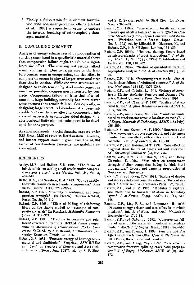
Figure 3: Simple model for energy release analysis and size effect curve.
Consideration of the global energy release was brought into the modeling of compression failure in a study of the compression breakout of boreholes in rock (Bazant et aI., 1993). A band of parallel splitting cracks was considered to propagate from the sides of the borehole, driven by the release of strain energy from the surrounding rock mass. It was shown that such a model predicts a size effect, which basically agrees with recent test results of Haimson (1989), Carter (1992) and Carter et al. (1992). This solution contrasts with previous plasticity solutions of borehole breakout which predict no size effect. The stored energy release due to propagation of a band of axial splitting cracks, coupled with buckling of the slabs of material between the cracks, have been two principal aspects of a model recently proposed by Bazant et al. (1993) which will serve as the basis of the present analysis.
A nonlocal constitutive model for strain-softening
252
damage, capable of capturing the energy release, was used by Droz and BaZant (1989) and BaZant and Ozbolt (1992) for finite element modeling of compressed rectangular specimens. These studies predicted for such specimens no significant size effect. The explanation is that the specimen was too small for developing a significant energy release. In that case, propagation of a long axial splitting crack is the preferred mechanism of failure, and this mechanics exhibits no size effect.
3. SIZE EFFECT IN COMPRESSION FRAC-TURE
To analyze global compression fracture, BaZant (1993), and BaZant and Xiang (1997) introduced the hypothesis that the aforementioned micromechanisms create a laterally propagating band of axial splitting cracks; see Fig. 3a,b,c. The band propagates in a direction either inclined or orthogonal to the direction of the compressive stress of the largest magnitude (BaZant, 1993, BaZant and Xiang, 1997). In the post-peak regime, the axial splitting cracks interconnect to produce what looks as a shear failure (Fig. 3b,c) although there is no shear slip before the post-peak softening (in fact, shear failure per se is probably impossible in concrete).
It is instructive to show by a simple energy analysis that a size effect must be exhibited by the prismatic specimen shown in Fig. 3a,b,c. Formation of the localized band axial splitting cracks, accompanied by buckling of the slabs of the material between the splitting cracks, as shown in the figure (which can be regarded as internal buckling of microscopically damaged continuum), engenders a reduction of stress on the flanks of the band (in the wake of the propagating band front); Fig. 3d. Approximately, a full stress reduction may be considered to occur in the shaded triangular areas. For the calculation of the energy change within the crack band one needs to take into account the fact that the slabs of material between the axial splitting cracks ought to undergo significant post-buckling deflections corresponding to the horizontal line 3-5 in Fig. 3e. Thus, the energy change in the splitting crack band is given by the difference of the areas 0120 and 03560 (the fact that there is a residual ~ress U cr in compression fracture is an important difference from a similar analysis of tensile crack band propagation) .
The energy released must be consumed and dissipated by the axial splitting cracks within the band. This is one condition of failure, for which the fracture energy of the band, Gb, is the essential material characteristic. Its value may be expressed as
(1)
where G j = mode I fracture energy of the axial splitting cracks; s = characteristic spacing of these cracks, and w = width of the splitting crack band. In general, parameter s as well as w may vary along the band and may also depend on the structure size D. It appears, however, that the available experimental data for concrete and rock, as scattered as they are, can be fitted reasonably well with the assumption that Gb = material constant. Yet, they can be fitted equally well under the hypothesis that the s-value is governed by buckling of the microslabs between the cracks according to the"Euler's critical stress formula. In that case, for a given D, there exists a certain finite value of s for which UN
is minimized (because increasing s causes the microbuckling stress to increase but Gb to decrease). For large D, the asymptotic behavior is the found to be
(2)
where So, Do = constants (BaZant 1993, BaZant et a1. 1993, BaZant and Xiang 1997). However, if the spacing s is of the same order of magnitude as the size of material inhomogeneities, then s may be a constant, independent of D. For example, when continuum analysis indicates s to be less than the spacing of the large aggregate pieces in concrete, then s is forced to be equal to that spacing, and thus constant.
The second condition of failure is that the relative displacement across the compressed band due to microslab buckling must be compatible with the expansion of the triangular areas in the flanks caused by the stress relief. One needs to write the condition that the shortening of segment HI in Fig. 3a is compensated for by the extension of segments GH and IJ, which is a compatibility condition. The energy release from the crack band is given by the change of the areas under the stress-strain diagrams in Fig. 3e, caused by the drop of stress from the initial compressive stress Uo to the final compressive stress Ucr carried by the splitting crack band.
The resulting asymptotic size effect on the nominal strength UN of large structures is given by a formula of the following form (BaZant 1993, ~!zant and Xiang 1997), in which Co, C l , Ur = constants;
or UN
CoVEGjwD-1/2 + U r
C1D-2/ s + U r (3)
depending on whether s varies according to (2) or is constant. For s varying according to (2), the plots of log UN and log( UN - ur ) versus log D are shown in Fig. 3f.
253
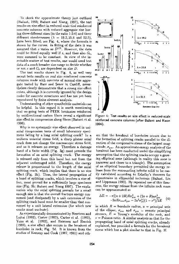
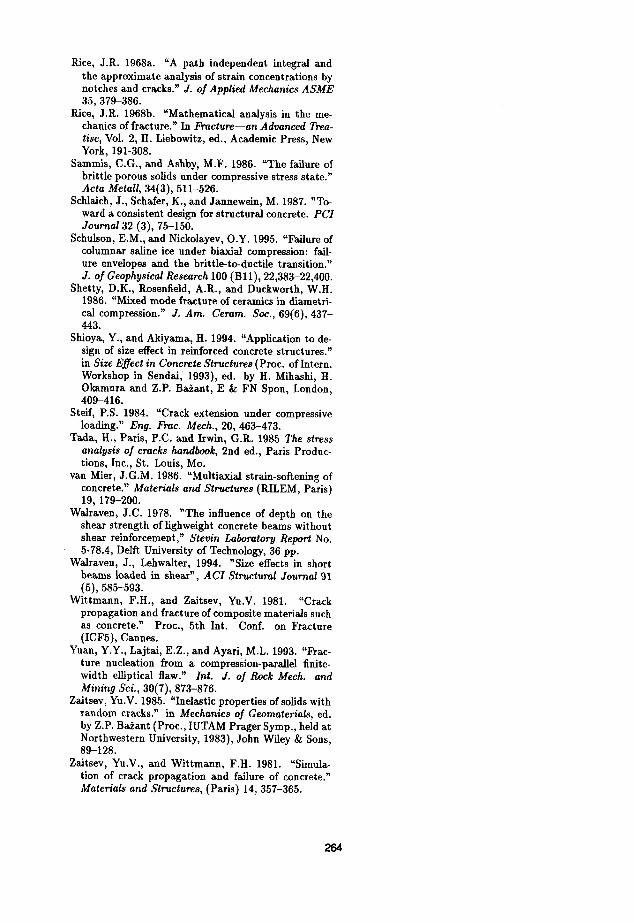
To check the approximate theory just outlined (Bazant, 1993; Bazant and Xiang, 1997), the test results on size effect in reduced-scale tied reinforced concrete columns with reduced aggregate size having three different sizes (in the ratio 1:2:4) and three different slendernesses (>. = 19.2,35.8 and 52.5), have been fitted; see Fig. 4, where the formula is shown by the curves. In fitting of the data it was assumed that s varies as Dl/5. However, the data could be fitted equally well if s, and thus also Gb,
were assumed to be constant. In view of the inevitable scatter of test results, one would need test data of a much broader size range to decide whether or not sand Gb are dependent on size D.
(a)
o A..s2.5
(b)
,,".51 2 .5 1 2 .51 2
(d) 5 ---________ ,
A.= 19.2
-"'Q , 5
o~~ ",,~
o ", "'"
2 ,.
The test results shown in Fig. 4, as well very recent tests results on real size reinforced concrete (e)
columns made with concrete of normal-size aggregate tested by Barr and Sener in Cardiff, nevertheless clearly demonstrate that a strong size effect exists, although it is currently ignored by the design codes for concrete structures and has not yet been reproduced by finite element analysis.
I L
1
.7''b.1 2 :I 4 5.7181 2 ,.
Understanding of other quasibrittle materials can be helpful. In this regard it is worth mentioning that on-going tests of PEEK laminates reinforced by unidirectional carbon fibers reveal a significant size effect in compression along fibers (Bazant et al. 1998).
Why is no systematic size effect observed in uniaxial compression tests of small laboratory specimens failing by a long axial splitting crack? In a uniform uniaxial stress field, a sharp planar axial crack does not change the macroscopic stress field, and so it releases no energy. Therefore a damage band of a finite width (Fig. 3g) must precede the formation of an axial splitting crack. The energy is released only from this band but not from the adjacent undamaged solid. Therefore, the energy release is proportional to the length of the axial splitting crack, which implies that there is no size effect (Fig. 3h). Thus, the lateral propagation of a band of splitting cracks, which involves a size effect, must prevail for a sufficiently large specimen size (Fig. 3h; Bazant and Xiang 1997). The explanation why the axial splitting prevails for a small enough size is that the overall fracture energy consumed (and dissipated) by a unit extension of the splitting crack band must be smaller than that consumed by a unit lateral extension (for which new cracks must nucleate).
As experimentally demonstrated by Nesetova and Lajtai (1992), Carter (1992), Carter et al. (1992), Yuan et al. (1992), and Haimson and Herrick (1989), a size effect also occurs in the breakout of boreholes in rock; Fig. 2d. It is known from the studies of Kemeny and Cook (1987, 1981) and oth-
254
:z :I 451'''1 2 ,.
Specimen Size (in)
p:
Figure 4: Test results on size effect in reduced-scale reinforced concrete columns (after Bahnt and Kwon 1994).
ers that the breakout of boreholes occurs due to the formation of splitting cracks parallel to the direction of the compressive stress of the largest magnitude, U yoo • An approximate energy analysis of the breakout has been conducted under the simplifying assumption that the splitting cracks occupy a growing elliptical zone (although in reality this zone is narrower and closer to a triangle). The assumption of an elliptical boundary permitted the energy release from the surrounding infinite solid to be easily calculated according to Eshelby's theorem for eigenstrains in ellipsoidal inclusions (Bazant, Lin and Lippmann 1993). By repeated use of this theorem, the energy release from the infinite rock mass can be approximated as
~n = -7r[(a + 2R)Ru;oo + (2a + R)au;oo -2aRuxoo uyoo - 2a2u;rl(1 - y2)/2E (4)
in which R = borehole radius, a = principal axis of the ellipse, u xoo and u yoo = remote principal stresses, E = Young's modulus of the rock, and y = Poisson ratio. A similar analysis as that for the propagating band of axial splitting cracks, already explained, has provided a formula for the breakout stress which has a plot similar to that in Fig. 3f.
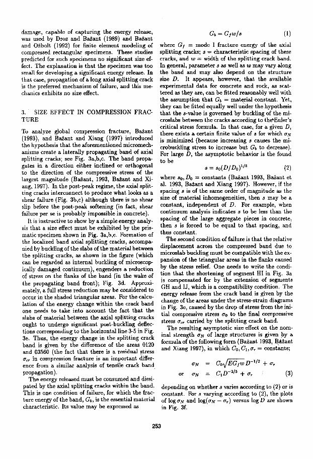
4 ASYMPTOTIC SIZE EFFECT VIA ENERGY RELEASE
4,1 Case of notches or long splitting crack band
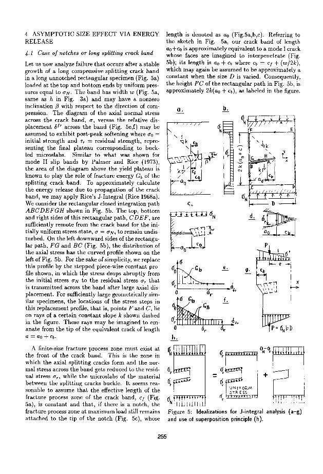
Let us now analyze failure that occurs after a stable growth of a long compressive splitting crack band in a long unnotched rectangular specimen (Fig. 5a) loaded at the top and bottom ends by uniform pressures equal to UN. The band has width w (Fig. 5a, same as h in Fig. 3a) and may have a nonzero inclination {3 with respect to the direction of compression. The diagram of the axial normal stress across the crack band, u, versus the relative displacement oJr across the band (Fig. 5e,f) may be assumed to exhibit post-peak softening where Uo = initial strength and Tr = residual strength, representing the final plateau corresponding to buckled microslabs. Similar to what was shown for mode II slip bands by Palmer and Rice (1973), the area of the diagram above the yield plateau is known to play the role of fracture energy Gb of the splitting crack band. To approximately calculate the energy release due to propagation of the crack band, we may apply Rice's J-Integral (Rice 1968a). We consider the rectangular closed integration path ABCDEFGH shown in Fig. 5b. The top, bottom and right sides of this rectangular path, CD E F, are sufficiently remote from the crack band for the initially uniform stress state, U = UN, to remain undisturbed. On the left downward sides of the rectangular path, FG and BC (Fig. 5b), the distribution of the axial stress has the curved profile shown on the left of Fig. 5b. For the sake of simplicity, we replace this profile by the stepped piece-wise constant profile shown, in which tJ.!.e stress drops abruptly from the initial stress UN to the residual stress U r that is transmitted across the band after large axial displacement. For sufficiently large geometrically similar specimens, the locations of the stress steps in this replacement profile, that is, points F and C, lie on rays of a certain constant slope k shown dashed in the figure. These rays may be imagined to emanate from the tip of the equivalent crack of length a = ao + Cb.
A finite-size fracture process zone must exist at the front of the crack band. This is the zone in which the axial splitting cracks form and the normal stress across the band gets reduced to the residual stress Un while the microslabs of the material between the splitting cracks buckle. It seems reasonable to assume that the effective length of the fracture process zone of the crack band, cJ (Fig. 5a), is constant and that, if there is a notch, the fracture process zone at maximum load still remains attached to the tip of the notch (Fig. 5c), whose
length is denoted as ao (Fig.5a,b,c). Referring to the sketch in Fig. 5a, our crack band of length ao+eo is approximately equivalent to a mode I crack whose faces are imagined to interpenetrate (Fig. 5b)j its length is ao + Cb where Cb = cJ + (w/2k), which may again be assumed to be approximately a constant when the size D is varied. Consequently, the height FC of the rectangular path in Fig. 5b, is approximately 2k(ao + Cb), as labeled in the figure.
Q. b.
.' / / / J
-' /' ,/,/
u
+ C>
S ..><
""
"
b,
II
9·
E
" I '1k " L 11'
/1
lJ kr' : (b
p
Figure 5: Idealizations for J-integral analysis (a-g) and use of superposition principle (h).
255
In view of these considerations, one part of the J-Integral may be expressed as follows:
(5)
in which W = strain energy density, and x, y = horizontal and vertical coordinates (Fig. 5b). In (2) we have considered that the parts of the integral over the horizontal segments are zero, and that the stress on the vertical segment DE may be assumed undisturbed by the band, Le., equal to (YN. The portions of the integral over the crack surface segments G Hand AB are, likewise, O.
The second part of the J-Integral may be calculated as follows:
f if· :~ dx = J GH (Yr ddx [~8(x)] dx
- J (Yr ~ [~8(x)] dx AB dx 2
- J::o(Yr d8(x)
-(Yr J::od8(x) = -(Yr8BG (6)
in which if = stress vector acting on the path from the outside, 11 = displacement vector, 6 = relative displacement across the band, and 8BG = relative displacement between points Band G. That displacement can be estimated as
8BG = 6.ED- (6.FG+6.BC) = 2k(ao + Cb)(Y;
aT aN - aT -2k(ao + Cb) E = 2k(ao + Cb)--E- (7)
As indicated, this value is calculated as the difference between the changes of length ED and length FG.
Now the J-Integral may be readily evaluated as follows:
f(- a11) J = W dy + if . ax dx
The energy consumed may be calculated again with the help of the J-Integral, in the manner shown by Rice (1968b) and Palmer and Rice (1973). To this end, the integration path that runs along the equivalent crack surface and crosses the crack (Fig. 5d) is used;
G c f ~ a11 b = Jer = -(YrVr + a' ax dx (9)
This represents the critical value Jer of the JIntegral; the first term, -ar 8", represents the work done by the band-bridging stresses that is leaving the fracture process zone in its wake; it is represented in Fig. 5f by the rectangle lying under the shaded triangle that gives the fracture energy. Following the way shown by Rice (1968b) and Palmer and Rice (1973), the second part of this expression may be evaluated as follows
a~
f~ u (Y' ax dx = - J:::>[6(x)J:x [~6(x)] dx
+ J::ao+J[6(x)J:x H6(x)] dx
- J:::>[6(x)Jd~~)dx J:' J[6(x)Jd6(x):= Gb (10)
As expected from the energy balance requirement, this result verifies expression (1) for crack band fracture energy.
Equating (8) and (9), and solving for the nominal strength of the specimen, aN, one obtains
in which (with ao = aol D)
ao = JEGb kc
( 12)
Note that the resulting formula (11) is of the same form as that proposed by Bazant (1987) for the general case vf quasibrittle failures with a residual plastic mechanism, and subsequently verified for several applications to concrete structure.
So far we have considered a long compression splitting crack band with uniform residual stress extending all the way from a smooth surface. In the case of a notch, the crack bridging stresses (Yr are zero up to the notch tip. Normally the fracture process at maximum load may be expected to be attached to the notch tip, which means one may obtain the solution from the previous solution (11) by simply substituting (Yr = O. This gives, for compression failure of notched specimens,
(Yo aN = VI + DIDo'
which is the same as the approximate size effect law proposed in Bazant (1983, 1984).
From laboratory evidence and computational experience, the length of the crack band up to the
256

beginning of the fracture process zone, ao, may often be considered to be roughly proportional to the specimen size D, within a certain range of sizes (Bazant and Planas 1998). In other words, the ratio D / ao is approximately constant, and so is the value of Do in (13), provided that the specimens are geometrically similar.
The foregoing procedure is generally valid for any type of distributed or concentrated load applied on the top and bottom of the specimen at remote cross sections. For the special case of a uniform load, the foregoing result can be more directly obtained by a simpler procedure that is based on the principle of superposition, as illustrated in Fig. 5h. The solution for a specimen with residual stress in the crack band is the sum of the solution of a specimen in which the distributed load at specimen ends is equal to the residual stress (in which case the stress state is uniform, (T = (Tr) and the solution of a specimen with a mode I stress-free crack loaded at remote cross sections by (TN - (Tr. In that case it suffices to take the J-Integral only along the path BCDEFG, that is, omit the segments AB and HG along the crack surface. In such an approach, (5) disappears, and so does the first term in (7). This leads directly to an expression of the type (13), but with (TN - (Tr
on the left-hand side, which evidently is equivalent to (10).
The case of a notched specimen can be treated as a special case of the preceding analysis in which the curve of band-bridging stress versus its relative displacement has the shape indicated in Fig. 5c, with a sudden drop to 0 at a certain point of the yield plateau, oc, corresponding to the transverse contraction of the crack band at the notch tip (the notch is assumed to have a certain finite width sufficient to accommodate this contraction without overlap). In a full analysis of the boundary value problem, the values of Oc and of the splitting crack band length would be determined by the condition that the total stress intensity factor caused by the applied load and the band-bridging stresses would vanish. However, imposing this condition would be too complicated for the present simplified analysis. Instead, it appears reasonable assume the crack band at the maximum load to have a certain finite length CF characteristic of the material. Then, the analysis that has led to (11) is applicable, except that (Tr is replaced in this formula by 0 and that Do = qD / ao. Thus, the approximate size effect law for geometrically similar notched specimens has the form of (12).
Another difference of failure of notched specimens (with fracture process zone at maximum load attached to the notch tip) is that the fracture en-
ergy of the splitting crack band must be considered as the area GB , which includes the area under the yield plateau shown in Fig. 5f. Consequently
(To = JEGfw/kcs.
4-2 Case of splitting crack band starting from smooth surface
As is well known, in prestressed concrete beams or in reinforced concrete columns, the bending failure may start by compression failure of concrete rather than tensile yielding of reinforcement. In view of the present analysis, such failure may be !(onsidered to occur at the initiation of a splitting crack band from the compressed face of the beam. However, unless the beam is enormously large, a fracture process zone whose length Cb is not negligible compared to the cross section depth D must form before the maximum load is reached (Fig. 5g). This must evidently cause significant stress redistribution, which may be seen as the source of the size effect.
This type of size effect is analogous to the size effect in tensile failure of plain concrete beams, i.e., in the test of modulus of rupture. It can be explained on the basis of energy release, however, one must for that purpose take into account the second-order derivatives of the energy release rate (because the energy release rate for an initiating crack or crack band, still infinitely short, is 0). The present simple .1-integral approach is not accurate enough for determining these higher-order derivatives. Therefore, the size effect can be more conveniently and perhaps more instructively explained and quantified by analyzing the stress redistribution (as already done for concrete in Bazant Li, 1995).
The size effect at crack band initiation is known to occur only if the stress distribution has a significant stress gradient (T' and a maximum magnitude at the surface (Fig. 5g). The remote stress distribution near the surface may be considered in the form:
in which x = distance from the surface; (TI, (T'
values of the stress and its gradient at the surface (x = 0) before any axial splitting cracks formed. If the stress distribution is calculated from the theory of bending and is caused by axial load P = (TNbD
of eccentricity e, then 'fJ = 6e/ D = dimensionless stress gradient.
A simple solution may proceed as follows. Based on experience with the analysis of size effect on the modulus of rupture of concrete, the stress under
257
maximum load at roughly the center of the fracture process zone, or precisely at distance Cb from the surface, may be assumed to be equal to the strength limit 0"0 at which the crack band begins to form, which corresponds to the maximum stress point on the diagram of band-bridging stress versus contraction of the band (Fig. 5c);
(15)
Solving this equation and introducing a large-size approximation valid for D < Db, one obtains the formula:
(16)
in which we introduced the notations:
0"00 = 0"0/(1 + 1/) (17)
For a vanishing stress gradient or a vanishing load eccentricity, 1/ = 0, and the size effect then vanishes. The values of 0"00 and Db are constants, the latter representing the thickness of the boundary layer in which the crack band damage takes place.
Equation (14) is of the same form as previously derived for concrete (BaZant and Li, 1995, BaZant and Planas, 1998). One could also obtain the same equation by a more sophisticated analysis in which the stress redistribution due to the formation of crack band is actually calculated and the maximum load is determined from the redistributed stresses (BaZant and Li, 1995). Such an analysis could also be applied here, but it is more complicated. A still more general approach is an asymptotic analysis based on the energy release functions of LEFM, which is outlined next.
5. ASYMPTOTIC SIZE EFFECT ANALYSIS VIA EQUIVALENT LEFM
5.1 Case of long notches or crack bands
Following a procedure analogous to BaZant (1997a), we will now try to express the coefficients of the size effect law in (11) on the basis of the energy release functions of linear elastic fracture mechanics (LEFM). This will further allow us to capture the effect of structure geometry (shape). Assuming that the fracture process zone at the crack band front is not so large as to spoil linearity, the stress intensity factor KJ at the tip of a Mode I crack approximately equivalent to the crack band may be expressed according to the principle of superposition as follows:
(18)
in which (with a = a/D)
(19)
Here a is the length of the equivalent LEFM crack, whose tip lies roughly in the middle of the fracture process zone of the crack band; Kf or K[ are the LEFM stress intensity factors caused by the applied load Palone (or by load system parameter P), or by a uniform normal traction 0" = O"r alone (Fig. 5h) applied on the crack faces (but not the notch faces, if any); g(a) and ,(a) are dimensionless energy release functions of LEFM, which can be obtained for various specimen geometries from handbooks (e.g. Tada et al. 1985) and can always be easily determined by linear elastic finite element analysis.
Since the crack band is propagating during failure, its energy release rate 9 must be critical, i.e., 9 = Gb = Gf(w/s). Therefore, in view of Ir-
win's relation KJ = ..;E'Q, we have O"NVDg(a) -
O"rvD,(a) = ..,fEUb. Consequently,
..[ErJb + O"rD,(a) O"N = Dg(a) (20)
The question now is what is the value of a or a at P ma",.
It is convenient to set a = ao + c or
a = ao + (c/D) (21)
If the specimens are notched and the notches for different sizes are geometrically similar, then ao = ao/ D = constant > 0 where ao = notch depth. If there is. no notch, ao represents the length of the portion of the crack band length along which the normal stress 0" transmitted across the band has already been reduced to the residual value O"ri ao = the distance from the beginning of the splitting crack band at the surface to the beginning of the fracture process zone (Fig. 5a).
In view of previous experimental studies and finite element results (BaZant and Planas 1998), it seems reasonable to introduce two simplifying hypotheses applicable when size D is not too small:
1. The value'of ao at maximum load Pma:J: is approximately constant over the practically interesting range of sizes D and,
2. the crack band extension c = a - ao at P ma", is also a constant, i.e., c = Cb, where Cb characterizes the effective length of the fracture process zone at the front of the splitting crack band (Fig. 5a).
258
Our analysis of scaling for notch-free structures failing only after a long crack band growth is predicated on the foregoing two hypotheses.
Large-Size Asymptotics: For geometrically similar notched specimens and, according to the foregoing hypotheses, for notch-free structures as well,
g(a) = g(ao + 0), ,(a) = ,(ao + 0) (22)
with 0 = Cb/ D. To deduce the large-size asymptotic behavior, we may expand the functions 9 and , into Taylor series with respect to 0 about point ao, and then truncate each series after the second (linear) term. So, we introduce into (20) the largesize approximations:
g(a) R:J go + g'O, (23)
in which go = g( ao), ,0 = ,( ao) and g' = dg(a)/da,,' = d,(a)/da at a = ao. After some rearrangement, this leads to the following size effect law for geometrically similar failures occurring only after and a long crack band growth:
Small-Size Asymptotics and Asymptotic Matching: To deduce the small-size asymptotic behavior, we introduce new parameter e = 1/0 = D/Cb and new LEFM functions
p(ao, ° = eg(ao +Ct), w(ao,e) = 6(ao +Ct
)
(25) Then we substitute g(a) = p(ao,e)/e and ,(a) = w(ao,O/e into (20), expand these functions into Taylor series in e about the point e = 0 (or D -+
0), and truncate the series after the second (linear) term. This furnishes
where PQ,wo,p',w' = constants. Expressing 9 and , from (25) and substituting into (20), we obtain, after rearrangements,
By algebraic rearrangement, the expression (24) for the large-size asymptotic approximation can be brought to the form:
UN = Uo + UY)1 + D/Dt
)1 +D/Do (28)
in which
" Uy =Ur -g'
(29) Under the aforementioned assumption that Gb and U r are constant, formula (28) has the following asymptotes:
for small D: UN = Uo + Uy = const.;
for large D: UN = UY) Do/ Dt = const. (30)
So the size effect curve of log UN - log Uy • versus 10gD (Fig. 3f) represents a gradual transition from a horizontal line, corresponding to the case of no size effect, as in plasticity, to a straight line of downward slope -1/2, corresponding to LEFM. The fact that the small-size asymptote is horizontal agrees with the fact that the strength theory or plasticity, which exhibits no size effect, ought to be a good approximation for small sizes because the failure is not localized.
It is interesting that the expression (27) for the small-size asymptotic approximation can be brought into the same form, in which
wo Uy =ur -
Po (31)
In contrast to the large-size asymptotic expressions (29), however, the small size asymptotic expressions (31) must not be expected to have predictive capability because the equivalent LEFM approximation, on which both are based, is physically justified _only for sufficiently large structures, in which the fracture process zone size at the front of the crack band is small compared to the structure dimensions. Therefore, the values of Do, Dt , Uo, Ut
for the small-size approximation may be assumed to be the same as given by (29) for the large-size approximation. With this assumption, the size effect law in (28) may be regarded as a matched asymptotic, i.e., a formula giving an asymptotica.lly correct 'interpolation' between opposite infinities in the 10gD scale (BaZant 1997a). This fact suggests that (28) should have a broad applicability. A similar conclusion has already been confirmed for concrete.
For the special case of Ur = 0, (24) or (28) reduces the previously established size effect law for quasibrittle fracture (BaZant and Kazemi 1990; Bazant and Planas 1998, Eq. 6.1.3; BaZant and Cedolin, Eq. 12.2.11; BaZant 199780).
The effect of structure geometry is captured in (24) by mea.ns of the functions 9 and , and their
259
derivatives. So the formula represents an approximate law for the effects of both the size and the shape.
Formula (11), which was derived for a long rectangular strip, is a special case of the general formula (28) for Dl = Do, i.e., for -yea) = g(a). This equivalence of the energy release functions means that the corresponding stress intensity factors are equal. This is immediately evident from the principle of superposition (see Fig. 5h, in which the middle specimen is in a homogeneous stress state and thus has no stress singularity, or KJ = 0).
In a similar manner as shown in Baiant (1997a) for cracked specimens, the foregoing analysis could be refined by considering that the splitting crack band ought to exhibit R-curve behavior. In other words, the critical energy release may be expected to follow an R-curve, such that 9 = Rb(C) where Rb( c) is assumed to be a given function of the crack band extension c. The only change needed in the preceding formulation is to replace the value VErJb in (20) by JERb(c). In addition to this, it becomes possible to implement in the calculations the condition of failure as a stability limit, which can be reduced to the condition that the curve of energy release rate at constant load is tangent to the R-curve (Bazant 1997a) (this condition cannot be imposed when the critical energy release rate is constant, being equal to Gb, as assumed in the preceding).
5.2 Case of crack band initiation from smooth surface
For crack bands originating from a smooth surface, the failure is likely to occur at the beginning of propagation. Therefore, the initial crack length for the LEFM approximation ao = 0, and so ao = O. But the energy release rate of a crack of zero length vanishes, g(ao) = -y(ao) = O. Thus, if we truncated the Taylor series expansion of g( ao+O) and -y( ao+O) after the linear term, we could not capture the size effect. Therefore we need to truncate these series only after the quadratic term. In this manner, the large-size approximation of (20) takes the form:
VErJb + O'rJ-Y'Cb + -y1l(cU2D) UN = (32)
V9'cb + gll(cU2D)
This may be rearranged as
JEGb/Cb + O'rJ-Y'(1 + 2Xt) UN = (33)
Jg'(1 - 2Xo)
with XO = -g"Cb/(4g'D),Xl = -Y"Cb/(4-y'D)j the notations are g' = dg(a)/da,-y' = d-y(a)/da,g" =
iPg(a)/da2,-y" = iP-y(a)/da2, all evaluated at a = ao = OJ Xo is defined with a minus sign because gil is, in bending specimens, negative (Bazant and Li 1996).
For large D we may introduce the asymptotic approximations -v'f+2Xt::::: 1 + Xt,I/~::::: 1 + Xo. After further rearrangement and after deleting a term with 1/ D2 which is higher-order small for large D, we obtain a size effect formula identical to (17), in which
We have thus obtained a more general confirmation of (17). Note that although the approximations that led from (33) to (34) are only first-order accurate in 1/ D, (32) is also only first-order accurate in 1/ D. So, these approximations cause no loss in accuracy overall. In fact, (34) can be applied more widely because it has acceptable behavior also for D -+ 0 while (33) does not.
Note that, in the foregoing formulae, Db and 0'00
are constant only if s and w, and thus also Gb, are constant. If s varies as described by (2), then these coefficients depend on D. Which case applies in various situations will have to be researched further.
6. FRACTURING TRUSS MODEL FOR SHEAR FAILURE OF REINFORCED CONCRETE
Local compression failure is also the decisive failure mechanism in global shear failures of reinforced concrete beams, such as diagonal shear of beams, torsion of beams, punching of plates, pullout of anchors, and failure of corbells, bar splices and frame connections, etc. The existence and importance of size effect in shear failure of beams has been experimentally documented by many investigators (Kani 1967, Walraven 1978, 1995; Iguro et al. 1985j Shioya et al. 1989j Shioya and Akiyama 1994; Baiant and Kazemi 1991; and Walraven and Lehwalter 1994j and Mihashi et a1. 1993). The size effect in diagonal shear failure of reinforced concrete beams can be explained by local compression failure (BaZant 1997b). Before closing this paper, we will review it briefly.
According to the truss model of Ritter and Morsch at the beginning of this century, later refined by Collins (1978), Schlaich et a1. (1987) and others, and recently called the strut-and-tie model, a good approximation is to assume that a system of inclined parallel cracks forms in the high shear
260

, ~.
Figure 6: Explanation of size effect by truss model for diagonal shear failure of beams.
zone of a reinforced concrete beam before the attainment of the maximum load (Fig. 6). The cracks are assumed to be continuous and oriented in the direction of the principal compressive stress (which is, of course, an approximation). This assumption implies that there is no shear stress on the crack planes and that the principal tensile stress has been reduced to o.
According to this simplified picture, the beam acts as a truss consisting of the longitudinal reinforcing bars, the vertical stirrups (which are in tension), and the inclined compression struts of concrete between the cracks. If the reinforcing bars and stirrups are designed sufficiently strong, there is only way the truss can fail-by compression of the diagonal struts.
In previous works, the compression failure of the struts has been handled according to the strength concept. This concept, however, cannot capture the localization of compression fracture and implies the compression fracture to occur simultaneously everywhere in the inclined strut. In reality, the compression fracture, called crushing, develops within only a portion of the length of the strut (in a region with stress concentrations, as on the top of beam in Fig. 6). Then it propagates across the strut. For the sake of simplicity, the band of axial splitting cracks forming the crushing zone may be assumed to propagate as shown in Fig. 6 and reach, at maximum load, a certain length c. The depth of the crushing band may be expected to increase initially but later to stabilize at a certain constant value h governed by the size of aggregate.
The mechanism of the size effect can now be applied easily. Because of the existence of parallel inclined cracks at maximum load, the formation of the crushing band reduces stress in the entire inclined white strip of width c and depth d (beam depth shown in Fig. 6). The area of the white strip
is cd and its rate of growth is cd So, the energy release rate is proportional to cd(u;'1 E), where the nominal strength is defined as UN = Vlbd = average shear stress, V = applied shear force and b = beam width. The energy consumed is proportional to the area of the cracking band, ch, that is, to c(G,hls), and its rate to c(G,hls) where G, = fracture energy of the axial splitting cracks and s = crack spacing. This expression applies asymptotically for large beams because for beams of a small depth d the full width h of the crushing band cannot develop. Equating the derivatives of the energy release and energy dissipation expressions, i.e. cd(u;'IE) DC c(G,hls), we conclude that the asymptotic size effect ought to be of the form:
UN DC .J E( G ,hi s) 1.Jd DC const. 1.Jd (35)
The complete size effect represents a transition from a horizontal asymptote to the inclined asymptote in the size effect plot given by this equation. Relatively simple design formulas are obtained in this manner (Baiant 1997b).
The analysis can also be done in a similar way for the diagonal shear failure of beams with longitudinal reinforcement but without vertical stirrups, and further for torsion, etc.
7. IMPLICATIONS FOR FINITE ELEMENT ANALYSIS
Although the present conference if focused on computer-aided design, there is no room but for a 'ew comments on the problem of developing finite ~lement code capable of handling compression fracure of concrete, in addition to tensile fracture and ;eneral nonlinear constitutive behavior.
1. Obviously, to capture localization of compression damage, a nonlocal model is required. However, if tensile fracture should be modeled by the same code, it is probably necessary to use a nonlocal model such as the nonlocal model based on microcrack interactions, in which the nonlocal interactions are tensorial rather than scalar, in order to distinguish between the amplifications zones and shielding zones of cracking damage (Bazant 1994b, Bazant and Jinisek 1994).
2. The strain-softening damage cannot be adequately described by the cohesive (fictitious) crack model, which is uniaxial. Rather, it must be described by a strain-softening triaxial COIl
stitutive law, such as the microplane model (Bazant et al. 1996).
261
3. Finally, a finite-strain finite element formulation with nonlinear geometric effects (BaZant et al. 1996) is requisite in order to capture the internal buckling of orthotropically damaged material.
8. CONCLUDING COMMENT
Analysis of energy release caused by propagation of splitting crack band in a quasi brittle material shows that compression failure ought to exhibit a significant size effect. The existing test results, albeit scant, confirm it. Due to larger size of the fracture process zone in compression, the size effect in compression comes to play at larger structural sizes than that in tension. While concrete structures are designed to resist tension by steel reinforcement as much as possible, compression is resisted by concrete. Compression failure, such as that of a column in a large building, normally has more severe consequences that tensile failure. Consequently, in designing large structural members, it appears advisable to take the size effect in compression into account, especially in computer-aided design. Suitable nonlocal finite element codes need to be developed for that purpose.
Acknowledgment: Partial financial support under NSF Grant MSS-9114426 to Northwestern University, and further support under a grant from the ACBM Center at Northwestern University, are gratefully acknowledged.
REFERENCES
Ashby, M.F., and H~am, S.D. 1986. "The failure of brittle solids containing small cracks under compressive stress states." Acta Metall., Vol. 34, No.3, 497-510.
Batto, R.A., and Schulson, E.M. 1993. "On the ductileto-brittle transition in ice under compression." Acta metal!. mater., 41(7), 2219-2225.
Bazant, Z.P. 1967. "Stability of continuum and compression strength." (in French), Bulletin RILEM, Paris, No. 39,99-112.
Bazant, Z.P. 1968. "Effect of folding of reinforcing fibers on the elastic moduli and strength of composite materials" (in Russian), Mekhanika Polimerov (Riga), 4, 314-321.
Bazant, Z.P. 1983. "Fracture in concrete and reinforced concrete," Preprints, IUTAM Prager Symposium on Mechanics of Geomaterials: Rocks, Concretes, Soils, ed. by Z.P. Bazant, Northwestern University, Evanston, Illinois, 281-316.
Bazant, Z.P. 1987. "Fracture energy of heterogeneous material and similitude." Preprints, SEM-RILEM Int. Con! on Fracture of Concrete and Rock (held in Houston, Texas, June 1987), ed. by S. P. Shah
262
and S. E. Swartz, publ. by SEM (Soc. for Exper. Mech.) 390-402.
Bazant, Z.P. 1994a. "Size effect in tensile and compressive quasibrittle failures." in Size Effect in Concrete Structures (Proc., Japan Concrete Institute Intern. Workshop held in Sendai, Japan, Oct.31-Nov.2, 1993), ed. by Mihashi, H., Okamura, H., and Bazant, Z.P., E & FN Spon, London, 161-180.
Bazant, Z.P. 1994b. "Nonlocal damage theory based on micromechanics of crack interactions." J. of Engrg. Mech., ASCE, 120 (3), 593-617; Addendum and Errata Vol. 120, 1401-02.
Bazant, Z.P. 1997a. "Scaling of quasibrittle fracture: Asymptotic analysis." Int. J. of Fracture 83 (1), 19-40. •
Bazant, Z.P. 1997b. "Fracturing truss model: Size effect in shear failure of reinforced concrete." J. of Engrg. Mechanics 123 (12), 1276-1288.
Bazant, Z.P., and Cedolin, 1. 1991. Stability of Structures: Elastic, Inelastic, Fracture and Damage Theories, Oxford University Press, New York, 1991.
Bazant, Z.P., and Chen, E.-P. 1997. "Scaling of structural failure." Applied Mechanics Reviews ASME 50 (10),593-627.
Bazant, Z.P., and Jirasek, M. 1994. "Nonlocal model based on crack interactions: A localization study". J. of Engrg. Materials & Technology, ASME116 (July), 256-259.
Bazant, Z.P., and Kazemi, M. T. 1990. "Determination of fracture energy, process zone length and brittleness number from size effect, with application to rock and concrete." Int. J. of Fracture, 44,111-131.
Bazant, Z.P., and Kazemi, M.T. 1991. "Size effect on diagonal shear failure of beams without stirrups." ACI StructufYJI Journal 88 (3), 268-276.
Bazant, Z.P., Kim, J.-J., Daniel, I.M., and BecqGiraudon, E. 1998. "Size effect on compression strength of fiber composites failing by kink band propagation." Report and paper in preparation at Northwestern University.
Bazant, Z.P., and Kwon, Y.W. 1994. "Failure of slender and stocky reinforced concrete columns: Tests of size effect." Materials and Structures (Paris), 27, 79-90.
Bazant, Z.P., and Li, Z. 1995. "Modulus of rupture: size effect due to fracture initiation in boundary layer." J. of Struct. Engrg. ASCE, 121 (4), 739-746.
Bazant, Z.P., Lin, F.-B., and Lippmann, H. 1993. "Fracture energy release and size effect in borehole breakout", Int. J. of Num. and Anal. Methods in Geomechanics, 17, 1-14.
Bazant, Z.P., and Ozbolt, J. 1992. "Compression failure of quasibrittle material: nonlocal microplane model." ASCE J. of Engng. Mech., 118(3),540-556.
Bazant, Z.P., and Planas, J. 1998. Fracture and Size Effect in Concrete and Other Quasibrittle Materials. CRC Press, Boca Raton and London.
Bazant, Z.P., and Xiang, Yuyin 1997. "Size effect in compression fracture: splitting crack band propagation." J. of Engrg. Mechanics ASCE 123 (2), 162-172. -

Bazant, Z.P., Xiang, Y., and Prat, P.C. 1996. "Microplane model for concrete. I. Stress-strain boundaries and finite strain." ASCE J. of Engrg. Mechanics 122 (3), 245-254.
Bieniawski, Z.T. 1974. "Estimating the strength of rock materials." J. of S. Afr. Inst. Min. Metal, 74,312-320.
Biot, M.A. 1965. Mechanics of Incremental Deformations, John Wiley & Sons, New York.
Blanks, R.F., and McNamara, C.C. 1935. "Mass concrete tests in large cylinders." J. of American Concrete Institute 31, 280-303.
Budianski, B. and Fleck, N.A. 1994. "Compressive kinking of fiber composites: A topical review." Applied Mechanics Reviews ASME 47 (6), pp.
Carter, B.C. 1992. "Size and stress gradient effects on fracture around cavities." Rock Mech. and Rock Engng. (Springer) 25(3), 167-186.
Carter, B.C., Lajtai, E.Z., and Yuan, Y. 1992. "Tensile fracture from circular cavities loaded in compression." Int. J. of Fracture, 57, 221-236.
Collins, M.P. 1978. "Towards a rational theory for RC members in shear." ASCE J. of the Structural Division 104 (Apr.), 396-408.
Cotterell, B. 1972. "Brittle fracture in compression", Int. J. of Fracture Mech., 8(2), 195-208.
Cotterell, B., and Rice, J.R. 1980. "Slightly curved or kinked cracks." Intern. J. of Fracture 16, 155-169.
Droz, P., and Bazant, Z.P. 1989 "Nonlocal analysis of stable states and stable paths of propagation of damage shear bands." in Cracking and Damage (Proc. of France-US Workshop held in Cachen, France 1988), ed. by J. Mazars and Z.P. BaZant, Elsevier, London, 183-207.
Fairhurst, C., and Cornet, F. 1981. "Rock fracture and fragmentation." Proc., 22nd U.S. Symp. on Rock Mechanics, (held at MIT, June) 21-46.
Gonnermann, H.F. 1925. "Effect of size and shape of test specimen on compressive strength of concrete." Proc. ASTM 25, 237-250.
Haimson, B.C., and Herrick, C.G. 1989. "In-site stress calculation from borehole breakout experimental studies." Proc., 26th U.S. Symp. on Rock Mech., 1207-1218.
Hoek, E., and Bieniawski, Z.J. 1965. "Brittle fracture propagation in rock under compression." Int. J. of Fracture Mech., 1, 137-155.
Horii, H., and Nemat-Nasser, S. 1982. "Compressioninduced nonplanar crack extension with application to splitting, exfoliation and rockburst." J. of Geophysical Research 87,6806-6821.
Horii, H., and Nemat-Nasser, S. 1986. "Brittle failure in compression, splitting, faulting and brittleductile transition." Phil. Tran. Royal Soc. London, 319(1549),337-374.
Hsu, T.T.C. 1985. "Softened truss model theory for shear and torsion." ACI Structural Journal 85 (6), 624-635.
Hsu, T.T.C. 1993. "Unified theory of reinforced concrete." CRC Press.
Ingraffea, A.R. 1977. Discrete fracture propagation in rock: Laboratory tests and finite element analysis, Ph.D. Dissertation, University of Colorado, Boulder.
Jishan, X., and Xixi, H. 1990. "Size effect on the strength of a concrete member." Engrg. Fracture M echanics 35,687-696.
Iguro, M., Shiyoa, T., Nojiri, Y., and Akiyama, H. 1985. "Experimental studies on shear strength of large reinforced concrete beams under uniformly distributed load, Concrete Library International, Japan Soc. of Civil Engrs. No.5, 137-154 (translation of 1984 article in Proc. JSCE).
Ingraffea, A.R., and Heuze, F.E. 1980. "Finite\!lement models for rock fracture mechanics." Int. J. of Numer. and Anal. Meth. in Geomechanics, 4, 25.
Jelf, P.M., and Fleck, N.A. 1992. "Compression failure mechanisms in unidirectional composites." J. of Composite Materials 26 (18),2706-2726.
Kachanov, M. 1982. "A microcrack model of rock inelasticity-Part I. Frictional sliding on microcracks." Mechanics of Materia16 1 1982), 19-41.
Kani, G.N.J. 1967. "Basic Facts Concerning Shear Failure," ACI Journal, Proceedings 64 (3, March), 128-141.
Kemeny, J.M., and Cook, N.G.W. 1987. "Crack models for the failure of rock under compression." Proc., 2nd Int. Conf. on Constitutive Laws for Eng. Mat. (held in Tucson), ed. by C.S. Desai et al., Elsevier Science Publ., New York, Vol. 2, 879-887.
Kemeny, J.M., and Cook, N.G.W. 1991. " Micromechanics of deformation in rock." in Toughening Mechanisms in Quasibrittle Materials, ed. by S.P. Shah et al., Kluwer, Netherlands, 155-188.
Kendall, K. 1978.· "Complexities of compression failure", Proc. Royal Soc. London., A., 361, 245-263.
Lehner, F., and Kachanov, M. 1996. "On modeling of "winged" cracks forming under compression." Intern. J. of Fracture, in press.
Marti, P. 1989. "Size effect on double punch tests on concrete cylinders." ACI Materials Journal 86 (6), 597-601.
Mihashi, H. Okamura, H., and Bazant, Z.P., Editors 1994. Size Effect in Concrete Structures. E& FN Spon, London (Proc. of JCI Intern. Workshop held in Sendai, Japan, 1993).
Murakami, Y. 1987. Stress intensity factors Handbook. Pergamon Press.
Nesetova, V., and Lajtai, E.Z. 1973. "Fracture from compressive stress concentration around elastic flaws." Int. J. of Rock Mech. and Mining Sci., 10, 265-284.
Nemat-Nasser, S., and Obata, M. 1988. "A micro crack model of dilatancy in brittle material." ASME J. of Applied Mechanics 55, 24-35.
Paul, B. 1968. "Macroscopic criteria for plastic flow and brittle fracture." in Fracture, an Advanced Treatise, ed. by. H. Liebowitz, Vol. 2, Chapter 4.
263
Rice, J.R. 1968a. "A path independent integral and the approximate analysis of strain concentrations by notches and cracks." J. of Applied Mechanics ASME 35, 379-386.
Rice, J.R. 1968b. "Mathematical analysis in the mechanics offracture." In Fracture-an Advanced Treatise, Vol. 2, H. Liebowitz, ed., Academic Press, New York, 191-308.
Sammis, C.G., and Ashby, M.F. 1986. "The failure of brittle porous solids under compressive stress state." Acta Metall, 34(3), 511-526.
Schlaich, J., Schafer, K., and Jannewein, M. 1987. "Toward a consistent design for structural concrete. PCI Journal 32 (3), 75-150.
Schulson, E.M., and Nickolayev, O.Y. 1995. "Failure of columnar saline ice under biaxial compression: failure envelopes and the brittle-to-ductile transition." J. of Geophysical Research 100 (Bll), 22,383-22,400.
Shetty, O.K., Rosenfield, A.R., and Duckworth, W.H. 1986. "Mixed mode fracture of ceramics in diametrical compression." J. Am. Ceram. Soc., 69(6), 437-443.
Shioya, Y., and Akiyama, H. 1994. "Application to design of size effect in reinforced concrete structures." in Size Effect in Concrete Structures (Proc. ofIntern. Workshop in Sendai, 1993), ed. by H. Mihashi, H. Okamura and Z.P. Bazant, E & FN Spon, London, 409-416.
Steif, P.S. 1984. "Crack extension under compressive loading." Eng. Frac. Mech., 20, 463-473.
Tada, H., Paris, P.C. and Irwin, G.R. 1985 The stress analysis of cracks handbook, 2nd ed., Paris Productions, Inc., St. Louis, Mo.
van Mier, J.G.M. 1986. "Multiaxial strain-softening of concrete." Materials and Structures (RILEM, Paris) 19, 179-200.
Walraven, J.C. 1978. "The influence of depth on the shear strength of lighweight concrete beams without shear reinforcement," Stevin Laboratory Report No. 5-78.4, Delft University of Technology, 36 pp.
Walraven, J., Lehwalter, 1994. "Size effects in short beams loaded in shear", ACI Structural Journal 91 (5),585-593.
Wittmann, F.H., and Zaitsev, Yu.V. 1981. "Crack propagation and fracture of composite materials such as concrete." Proc., 5th Int. Conf. on Fracture (ICF5), Cannes.
Yuan, Y.Y., Lajtai, E.Z., and Ayari, M.L. 1993. "Fracture nucleation from a compression-parallel finitewidth elliptical flaw." Int. J. of Rock Mech. and Mining Sci., 30(7), 873-876.
Zaitsev, Yu.V. 1985. "Inelastic properties of solids with random cracks." in Mechanics of Geomaterials, ed. by Z.P. Bazant (Proc., IUTAM Prager Symp., held at Northwestern University, 1983), John Wiley & Sons, 89-128.
Zaitsev, Yu.V., and Wittmann, F.H. 1981. "Simulation of crack propagation and failure of concrete." Materials and Structures, (Paris) 14,357-365.
264


