
5/12/2018 Configuring Expanded Switched Networks Vlans and Vtp - slidepdf.com
http://slidepdf.com/reader/full/configuring-expanded-switched-networks-vlans-and-vtp
Lab: CONFIGURING EXPANDED SWITCHEDNETWORKS: VLANs and VTP
Lab Summary
Lab Summary
vLab Title 336317 CONFIGURING EXPANDED SWITCHED NETWORKS: VLANs and VTPSkills By completing the lab, you will be able to:
Configure a VTP domain.Change the VTP mode set on the switch.Verify your VTP settings with show commands.Configure 802.1Q encapsulation to be used on trunk ports.
Enable trunking between switches.Configure a default gateway for the switch to use.Create VLANs.Assign ports to become members of a VLAN.Configure portfast on an interface.Configure a default route.Verify your work with ping and show commands.
Level Of Difficulty BasicCourse ICND2Lab Length 60 minutesCertification CCNADesired Learner Outcome You will gain the skills required for the practical portion of the CCNA certification and
will be able to configure and troubleshoot small Cisco networks.Desired Network Outcome Working through these labs, you will gain hands-on experience and practice in
implementing and operating a simple Cisco network that includes real switches,routers, and remote access technologies.
DependenciesAuthor Trey McMahonVendor
Network Type Cisco SPV2Technology CiscoReferences Cisco Systems, Interconnecting Cisco Network Devices 2 , Cisco Systems, Inc., Cisco
authorized courseware for CCNA certification.James Boney, Cisco IOS In a Nutshell , O'Reilly, A Desktop Quick Reference for IOSon IP Networks
Lab ScenarioScenario
Quick Start Instructions Assignment Story Conditions Notes Diagram
Quick Start Instructions
Once a lab has finished initializing, click on the Sample Solution link if one is available. For performance based labs,Sample Solution will not be available. IT IS IMPORTANT TO WAIT UNTIL AFTER INITIALIZATION BEFORE GOINGTO THE SAMPLE SOLUTION. The reason is that during initialization, you are assigned custom IP addresses that aredynamically added to your lab instructions. This makes the lab easier to follow than the traditional method of trying tolook up pod-specific information in tables. After initialization, the Sample Solution will have the correct information for your gear.
To console into the routers and switches mentioned in the lab steps, click on the network diagram shown on the mainpage.
5/12/2018 Configuring Expanded Switched Networks Vlans and Vtp - slidepdf.com
http://slidepdf.com/reader/full/configuring-expanded-switched-networks-vlans-and-vtp
Once you have completed a lab, if you have additional time and wish to take it again, go to the Device Controls link andclick on Reload. When the devices are ready, you can start the lab again.
Assignment
Gain skills required for practical portion of CCNA certification by completing tasks outlined below.
The Suggested Approach steps are provided to test your mastery when taking a vLab for the second time. For your firstattempt, follow the steps listed under Sample Solution.
CONFIGURING EXPANDED SWITCHED NETWORKS: VLANs and VTP
1) Console into Sw1. Shut down ports 1 and 12.
2) On Sw1, enable port 11, the interface that connects to CoreSwA.
3) On Sw1, set the VTP domain name to ICND.
4) On Sw1, set the VTP mode to transparent.
5) Verify the VTP configuration using a show command.
6) Set the trunk encapsulation type on port 11 to 802.1Q.
7) Set port 11 on Sw1 to trunk mode.
8) Verify the trunk configuration.
9) To verify trunk connectivity, ping the core router at 10.1.1.5 from Sw1.
10) Configure 10.1.1.5 to be the default gateway on Sw1.
11) On Sw1, create VLAN 11.
12) Using the show vlan command from the EXEC mode, verify that the correct VLAN has been added.
13) On Sw1, assign port 2, which is connected to R1, to VLAN 11.
14) On Sw1, configure portfast on port 2.
15) Enter the proper show command for verifying that port 2 is now in the correct VLAN.
16) Console to R1. Change the address and subnet mask on f0/0 to 10.1.50.1 255.255.255.0.
17) From R1, ping the core router’s 10.1.50.5 address.
18) On R1, enable inter-VLAN communications by configuring a default route that points to the core router’s 10.1.50.5address.
19) From R1, verify that inter-VLAN routing is taking place by pinging Sw1: 10.1.1.2.
20) You have finished this lab.
Once lab finishes initializing, click on Sample Solution link if you are launching it in non performance mode . IT ISIMPORTANT TO WAIT UNTIL AFTER INITIALIZATION BEFORE GOING TO SAMPLE SOLUTION. Reason is thatduring initialization, you are assigned custom IP addresses that are dynamically added to your lab instructions. Thismakes the lab easier to follow than the traditional method of trying to look up pod-specific information in tables. After initialization, Sample Solution will have correct information for your gear.
To console into routers and switches, click on network diagram shown on main page.
Once you have completed the lab, if you have additional time and wish to take it again, go to Device Controls link andclick on Reload. When the devices are ready, you can start the lab again.
In Performance Mode, Device configuration will be captured automatically by vLab platform once you either quit the labor lab timer counts down to zero. This is sent to email address you entered prior to starting the lab and will be used for assessment. There is no need for lab report for Cisco vLabs.
5/12/2018 Configuring Expanded Switched Networks Vlans and Vtp - slidepdf.com
http://slidepdf.com/reader/full/configuring-expanded-switched-networks-vlans-and-vtp
Story
N/A
Conditions
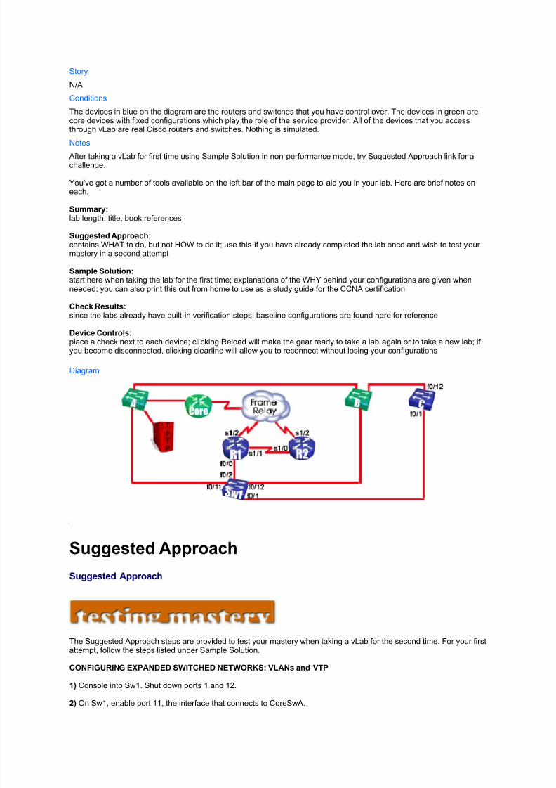
The devices in blue on the diagram are the routers and switches that you have control over. The devices in green arecore devices with fixed configurations which play the role of the service provider. All of the devices that you accessthrough vLab are real Cisco routers and switches. Nothing is simulated.
Notes
After taking a vLab for first time using Sample Solution in non performance mode, try Suggested Approach link for achallenge.
You've got a number of tools available on the left bar of the main page to aid you in your lab. Here are brief notes oneach.
Summary: lab length, title, book references
Suggested Approach: contains WHAT to do, but not HOW to do it; use this if you have already completed the lab once and wish to test your mastery in a second attempt
Sample Solution: start here when taking the lab for the first time; explanations of the WHY behind your configurations are given whenneeded; you can also print this out from home to use as a study guide for the CCNA certification
Check Results: since the labs already have built-in verification steps, baseline configurations are found here for reference
Device Controls: place a check next to each device; clicking Reload will make the gear ready to take a lab again or to take a new lab; if you become disconnected, clicking clearline will allow you to reconnect without losing your configurations
Diagram
Suggested ApproachSuggested Approach
The Suggested Approach steps are provided to test your mastery when taking a vLab for the second time. For your firstattempt, follow the steps listed under Sample Solution.
CONFIGURING EXPANDED SWITCHED NETWORKS: VLANs and VTP
1) Console into Sw1. Shut down ports 1 and 12.
2) On Sw1, enable port 11, the interface that connects to CoreSwA.
5/12/2018 Configuring Expanded Switched Networks Vlans and Vtp - slidepdf.com
http://slidepdf.com/reader/full/configuring-expanded-switched-networks-vlans-and-vtp
3) On Sw1, set the VTP domain name to ICND.
4) On Sw1, set the VTP mode to transparent.
5) Verify the VTP configuration using a show command.
6) Set the trunk encapsulation type on port 11 to 802.1Q.
7) Set port 11 on Sw1 to trunk mode.
8) Verify the trunk configuration.
9) To verify trunk connectivity, ping the core router at 10.1.1.5 from Sw1.
10) Configure 10.1.1.5 to be the default gateway on Sw1.
11) On Sw1, create VLAN 11.
12) Using the show vlan command from the EXEC mode, verify that the correct VLAN has been added.
13) On Sw1, assign port 2, which is connected to R1, to VLAN 11.
14) On Sw1, configure portfast on port 2.
15) Enter the proper show command for verifying that port 2 is now in the correct VLAN.
16) Console to R1. Change the address and subnet mask on f0/0 to 10.1.50.1 255.255.255.0.
17) From R1, ping the core router’s 10.1.50.5 address.
18) On R1, enable inter-VLAN communications by configuring a default route that points to the core router’s 10.1.50.5address.
19) From R1, verify that inter-VLAN routing is taking place by pinging Sw1: 10.1.1.2.
20) You have finished this lab.
Sample Solution
Sample Solution
Task Index
Task 1 CONFIGURING EXPANDED SWITCHED NETWORKS: VLANs and VTP
Task 1
CONFIGURING EXPANDED SWITCHED NETWORKS: VLANs and VTP
Step 1 : Console into Sw1. Shut down ports 1 and 12. Action: The vLab system has assigned you switches with either FastEthernet or GigabitEthernet ports. The commands for both types are listed here. If you are unsure as to which has been assigned for this lab, type both. You'll see errors for the ones that don't exist, but i t won't affect your labbecause the switch will simply ignore those lines.
sw1> enable
5/12/2018 Configuring Expanded Switched Networks Vlans and Vtp - slidepdf.com
http://slidepdf.com/reader/full/configuring-expanded-switched-networks-vlans-and-vtp
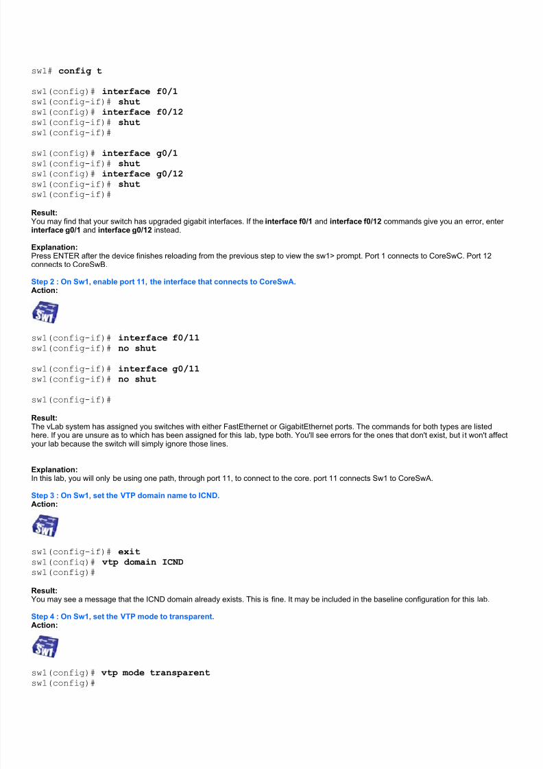
sw1# config t
sw1(config)# interface f0/1sw1(config-if)# shutsw1(config)# interface f0/12sw1(config-if)# shut
sw1(config-if)#
sw1(config)# interface g0/1sw1(config-if)# shutsw1(config)# interface g0/12sw1(config-if)# shutsw1(config-if)#
Result: You may find that your switch has upgraded gigabit interfaces. If the interface f0/1 and interface f0/12 commands give you an error, enter interface g0/1 and interface g0/12 instead.
Explanation: Press ENTER after the device finishes reloading from the previous step to view the sw1> prompt. Port 1 connects to CoreSwC. Port 12
connects to CoreSwB.
Step 2 : On Sw1, enable port 11, the interface that connects to CoreSwA. Action:
sw1(config-if)# interface f0/11sw1(config-if)# no shut
sw1(config-if)# interface g0/11sw1(config-if)# no shut
sw1(config-if)#
Result: The vLab system has assigned you switches with either FastEthernet or GigabitEthernet ports. The commands for both types are listedhere. If you are unsure as to which has been assigned for this lab, type both. You'll see errors for the ones that don't exist, but i t won't affectyour lab because the switch will simply ignore those lines.
Explanation: In this lab, you will only be using one path, through port 11, to connect to the core. port 11 connects Sw1 to CoreSwA.
Step 3 : On Sw1, set the VTP domain name to ICND. Action:
sw1(config-if)# exitsw1(config)# vtp domain ICNDsw1(config)#
Result: You may see a message that the ICND domain already exists. This is fine. It may be included in the baseline configuration for this lab.
Step 4 : On Sw1, set the VTP mode to transparent. Action:
sw1(config)# vtp mode transparentsw1(config)#
5/12/2018 Configuring Expanded Switched Networks Vlans and Vtp - slidepdf.com
http://slidepdf.com/reader/full/configuring-expanded-switched-networks-vlans-and-vtp
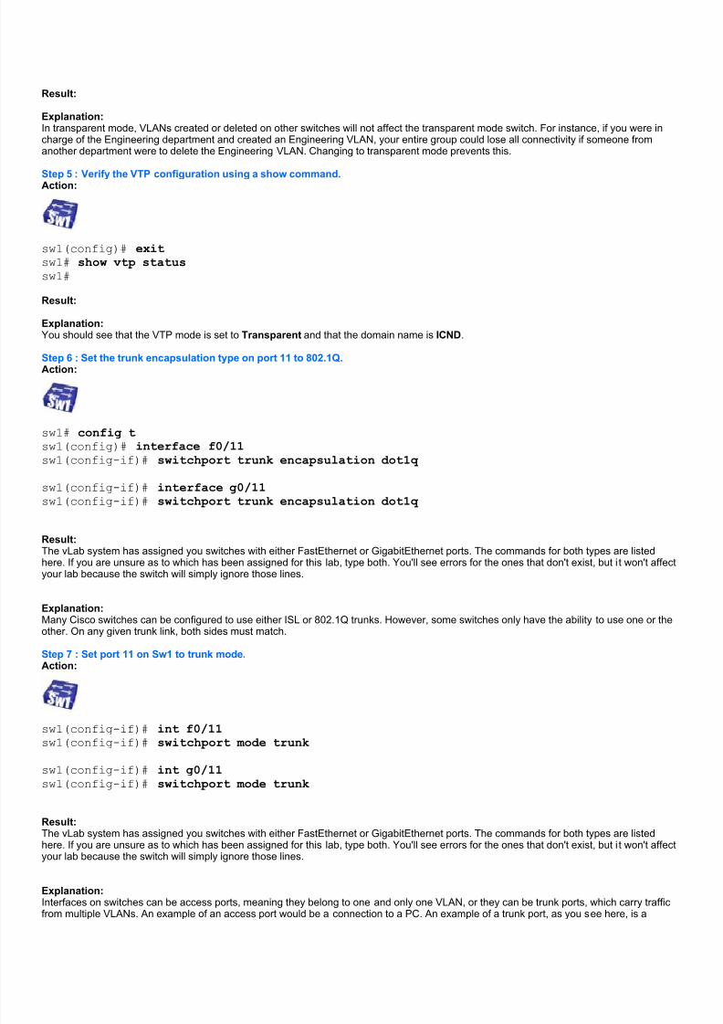
Result:
Explanation: In transparent mode, VLANs created or deleted on other switches will not affect the transparent mode switch. For instance, if you were incharge of the Engineering department and created an Engineering VLAN, your entire group could lose all connectivity if someone fromanother department were to delete the Engineering VLAN. Changing to transparent mode prevents this.
Step 5 : Verify the VTP configuration using a show command. Action:
sw1(config)# exitsw1# show vtp statussw1#
Result:
Explanation: You should see that the VTP mode is set to Transparent and that the domain name is ICND.
Step 6 : Set the trunk encapsulation type on port 11 to 802.1Q. Action:
sw1# config tsw1(config)# interface f0/11sw1(config-if)# switchport trunk encapsulation dot1q
sw1(config-if)# interface g0/11sw1(config-if)# switchport trunk encapsulation dot1q
Result: The vLab system has assigned you switches with either FastEthernet or GigabitEthernet ports. The commands for both types are listedhere. If you are unsure as to which has been assigned for this lab, type both. You'll see errors for the ones that don't exist, but i t won't affectyour lab because the switch will simply ignore those lines.
Explanation: Many Cisco switches can be configured to use either ISL or 802.1Q trunks. However, some switches only have the ability to use one or theother. On any given trunk link, both sides must match.
Step 7 : Set port 11 on Sw1 to trunk mode. Action:
sw1(config-if)# int f0/11sw1(config-if)# switchport mode trunk
sw1(config-if)# int g0/11sw1(config-if)# switchport mode trunk
Result: The vLab system has assigned you switches with either FastEthernet or GigabitEthernet ports. The commands for both types are listedhere. If you are unsure as to which has been assigned for this lab, type both. You'll see errors for the ones that don't exist, but i t won't affectyour lab because the switch will simply ignore those lines.
Explanation: Interfaces on switches can be access ports, meaning they belong to one and only one VLAN, or they can be trunk ports, which carry trafficfrom multiple VLANs. An example of an access port would be a connection to a PC. An example of a trunk port, as you see here, is a
5/12/2018 Configuring Expanded Switched Networks Vlans and Vtp - slidepdf.com
http://slidepdf.com/reader/full/configuring-expanded-switched-networks-vlans-and-vtp
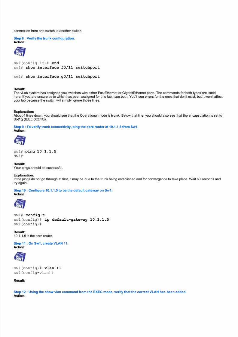
connection from one switch to another switch.
Step 8 : Verify the trunk configuration. Action:
sw1(config-if)# end sw1# show interface f0/11 switchport
sw1# show interface g0/11 switchport
Result: The vLab system has assigned you switches with either FastEthernet or GigabitEthernet ports. The commands for both types are listedhere. If you are unsure as to which has been assigned for this lab, type both. You'll see errors for the ones that don't exist, but i t won't affectyour lab because the switch will simply ignore those lines.
Explanation: About 4 lines down, you should see that the Operational mode is trunk. Below that line, you should also see that the encapsulation is set todot1q (IEEE 802.1Q).
Step 9 : To verify trunk connectivity, ping the core router at 10.1.1.5 from Sw1. Action:
sw1# ping 10.1.1.5sw1#
Result: Your pings should be successful.
Explanation: If the pings do not go through at first, it may be due to the trunk being established and for convergence to take place. Wait 60 seconds andtry again.
Step 10 : Configure 10.1.1.5 to be the default gateway on Sw1. Action:
sw1# config tsw1(config)# ip default-gateway 10.1.1.5sw1(config)#
Result:
10.1.1.5 is the core router.
Step 11 : On Sw1, create VLAN 11. Action:
sw1(config)# vlan 11sw1(config-vlan)#
Result:
Step 12 : Using the show vlan command from the EXEC mode, verify that the correct VLAN has been added. Action:
5/12/2018 Configuring Expanded Switched Networks Vlans and Vtp - slidepdf.com
http://slidepdf.com/reader/full/configuring-expanded-switched-networks-vlans-and-vtp
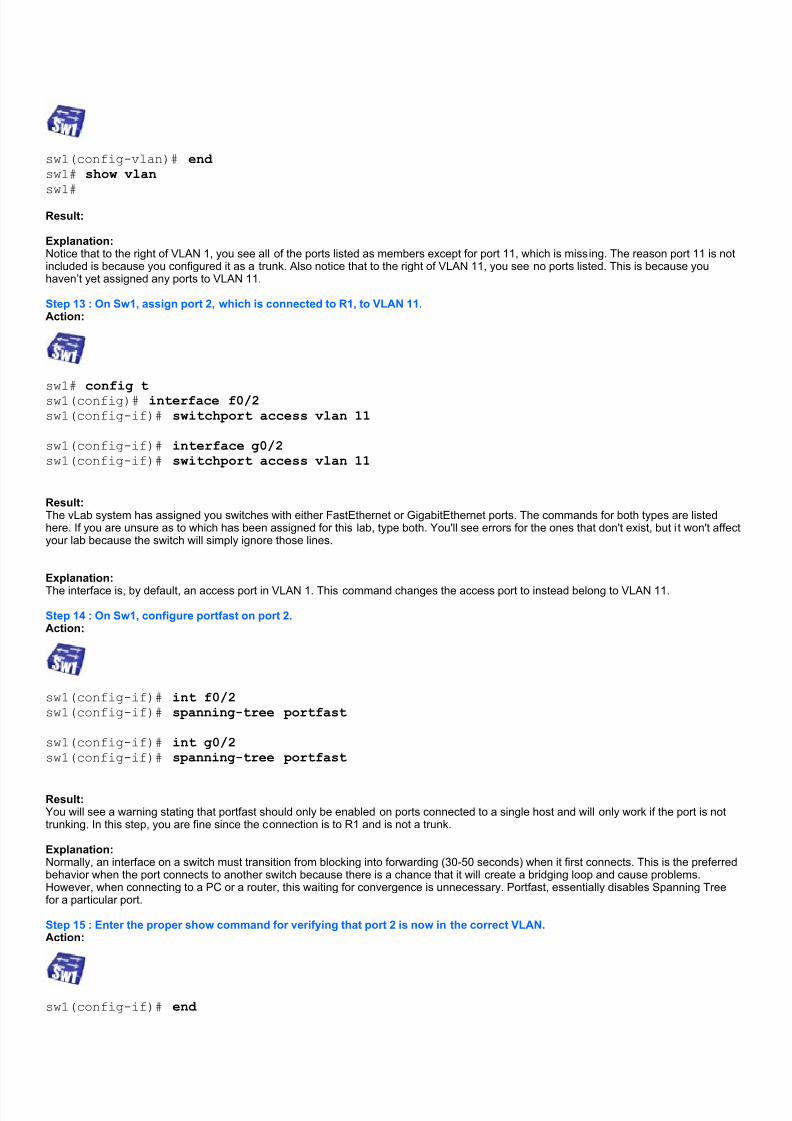
sw1(config-vlan)# end sw1# show vlan
sw1#
Result:
Explanation: Notice that to the right of VLAN 1, you see all of the ports listed as members except for port 11, which is missing. The reason port 11 is notincluded is because you configured it as a trunk. Also notice that to the right of VLAN 11, you see no ports listed. This is because youhaven’t yet assigned any ports to VLAN 11.
Step 13 : On Sw1, assign port 2, which is connected to R1, to VLAN 11. Action:
sw1# config tsw1(config)# interface f0/2sw1(config-if)# switchport access vlan 11
sw1(config-if)# interface g0/2sw1(config-if)# switchport access vlan 11
Result: The vLab system has assigned you switches with either FastEthernet or GigabitEthernet ports. The commands for both types are listedhere. If you are unsure as to which has been assigned for this lab, type both. You'll see errors for the ones that don't exist, but i t won't affectyour lab because the switch will simply ignore those lines.
Explanation:
The interface is, by default, an access port in VLAN 1. This command changes the access port to instead belong to VLAN 11.
Step 14 : On Sw1, configure portfast on port 2.Action:
sw1(config-if)# int f0/2sw1(config-if)# spanning-tree portfast
sw1(config-if)# int g0/2sw1(config-if)# spanning-tree portfast
Result: You will see a warning stating that portfast should only be enabled on ports connected to a single host and will only work if the port is nottrunking. In this step, you are fine since the connection is to R1 and is not a trunk.
Explanation: Normally, an interface on a switch must transition from blocking into forwarding (30-50 seconds) when it first connects. This is the preferredbehavior when the port connects to another switch because there is a chance that it will create a bridging loop and cause problems.However, when connecting to a PC or a router, this waiting for convergence is unnecessary. Portfast, essentially disables Spanning Treefor a particular port.
Step 15 : Enter the proper show command for verifying that port 2 is now in the correct VLAN.Action:
sw1(config-if)# end
5/12/2018 Configuring Expanded Switched Networks Vlans and Vtp - slidepdf.com
http://slidepdf.com/reader/full/configuring-expanded-switched-networks-vlans-and-vtp
sw1# show vlan briefsw1#
Result: Looking to the right of VLAN 11, you will see that port 2 is now a member. The rest of the interfaces are still in VLAN 1.
Step 16 : Console to R1. Change the address and subnet mask on f0/0 to 10.1.50.1 255.255.255.0.
Action:
r1> enabler1# config tr1(config)# interface f0/0r1(config-if)# ip address 10.1.50.1 255.255.255.0r1(config-if)#
Result: If you are prompted for passwords, cisco is the user mode password and sanfran is the enable mode password. Anytime you see a deviceblinking, it is a reminder to console into a new device.
Explanation: A VLAN is a subnet. If you have different VLANs, they must be on different subnets. Before you placed the Sw1 interface connecting to R1in VLAN 11, the router was in VLAN 1, on the 10.1.1.0 subnet. Now, the router is in VLAN 11 so the IP address had to be changed. VLAN 1is the 10.1.1.0 subnet and VLAN 11 is the 10.1.50.0 subnet.
Step 17 : From R1, ping the core router’s 10.1.50.5 address. Action:
r1(config-if)# end r1# ping 10.1.50.5r1#
Result: Your pings should be successful.
Explanation: One of the interfaces on the core router is in the same VLAN as R1. R1 should be able to ping it because they are in the same subnet,10.1.50.0. However, if you were to attempt to ping Sw1, 10.1.1.2, it would fail. The reason is that they are now in different subnets andinter-VLAN routing has not yet been configured.
Step 18 : On R1, enable inter-VLAN communications by configuring a default route that points to the core router’s 10.1.50.5address. Action:
r1# config tr1(config)# ip route 0.0.0.0 0.0.0.0 10.1.50.5r1(config)#
Result:
Explanation: The default route instructs R1 to send packets to 10.1.50.5 if all else fails. In other words, if a packet is destined for a route not explicitlyfound in the routing table, send it to the core router. The core router has interfaces in both VLAN 1 (10.1.1.5) and VLAN 11 (10.1.50.5).Therefore, it knows how to get to both subnets. Sw1 has a default gateway pointing to the core router as well, which acts just like thedefault route you just configured. At this point, the core router can now route packets between the two VLANs.
Step 19 : From R1, verify that inter-VLAN routing is taking place by pinging Sw1: 10.1.1.2. Action:
5/12/2018 Configuring Expanded Switched Networks Vlans and Vtp - slidepdf.com
http://slidepdf.com/reader/full/configuring-expanded-switched-networks-vlans-and-vtp
r1(config)# end r1# ping 10.1.1.2
r1#
Result: Your pings should be successful.
Step 20 : You have finished the lab. Action: You can take this lab again if time permits.
Result: To take the lab a second time, you first need to reset the devices back to the baseline configurations that were present at the beginning of the lab. This can be done by clicking on the Device Controls link on the left bar, selecting all devices, and clicking the Reload button.Once the devices are all marked green, you can begin the lab. This process takes several minutes.
You can also test your mastery of the material when you take the lab for the second time. Instead of using the Sample Solution link whichwalks you through each step, you can use the Suggested Approach link. This provides the same steps, but without the walkthrough.
Check Results
Check Results
This vLab was designed with verification commands and detailed explanations already built in to give you a deeper understanding of the technologies.
The routers and switches begin the lab with baseline configurations in place. The configurations for each device arelisted below for reference.
hostname r1
!
no ip domain lookup
!
interface FastEthernet0/0
description CONNECTION TO SW1
ip address 10.1.1.1 255.255.255.0
!
interface FastEthernet0/1shutdown
!
interface Serial1/0
shutdown
!
interface Serial1/1
description CONNECTION TO R2
ip address 10.1.0.1 255.255.255.0
!
interface Serial1/2
description CONNECTION TO FRAME SWITCH
ip address 172.41.1.1 255.255.255.0
encapsulation frame-relay
frame-relay map ip 172.41.1.5 41 broadcast
no frame-relay inverse-arp
5/12/2018 Configuring Expanded Switched Networks Vlans and Vtp - slidepdf.com
http://slidepdf.com/reader/full/configuring-expanded-switched-networks-vlans-and-vtp
!
interface Serial1/3
shutdown
!
line con 0
exec-timeout 30 0
logging synchronousline aux 0
line vty 0 4
logging synchronous
login
!
end
hostname r2
!no ip domain lookup
!
interface FastEthernet0/0
shutdown
!
interface FastEthernet0/1
shutdown
!
interface Serial1/0
description CONNECTION TO R1
ip address 10.1.0.2 255.255.255.0
clock rate 64000
!interface Serial1/1
shutdown
!
interface Serial1/2
description CONNECTION TO FRAME SWITCH
ip address 172.41.1.2 255.255.255.0
encapsulation frame-relay
frame-relay map ip 172.41.1.5 94 broadcast
no frame-relay inverse-arp
!
interface Serial1/3
shutdown
!line con 0
exec-timeout 30 0
logging synchronous
line aux 0
line vty 0 4
logging synchronous
login
!
end
5/12/2018 Configuring Expanded Switched Networks Vlans and Vtp - slidepdf.com
http://slidepdf.com/reader/full/configuring-expanded-switched-networks-vlans-and-vtp
hostname sw1
!
spanning-tree mode pvst
spanning-tree extend system-id
!
interface FastEthernet0/1
description CONNECTION TO CORESWCswitchport mode dynamic desirable
shutdown
!
interface FastEthernet0/2
description CONNECTION TO R1
switchport mode access
!
interface FastEthernet0/3
switchport mode dynamic desirable
!
interface FastEthernet0/4
switchport mode dynamic desirable
!interface FastEthernet0/5
switchport mode dynamic desirable
!
interface FastEthernet0/6
switchport mode dynamic desirable
!
interface FastEthernet0/7
switchport mode dynamic desirable
!
interface FastEthernet0/8
switchport mode dynamic desirable
!
interface FastEthernet0/9switchport mode dynamic desirable
!
interface FastEthernet0/10
switchport mode dynamic desirable
!
interface FastEthernet0/11
description CONNECTION TO CORESWA
switchport mode dynamic desirable
shutdown
!
interface FastEthernet0/12
description CONNECTION TO CORESWB
switchport mode dynamic desirableshutdown
!
interface FastEthernet0/13
switchport mode dynamic desirable
!
interface FastEthernet0/14
switchport mode dynamic desirable
!
interface FastEthernet0/15
switchport mode dynamic desirable
!
interface FastEthernet0/16
switchport mode dynamic desirable
!
interface FastEthernet0/17
5/12/2018 Configuring Expanded Switched Networks Vlans and Vtp - slidepdf.com
http://slidepdf.com/reader/full/configuring-expanded-switched-networks-vlans-and-vtp
switchport mode dynamic desirable
!
interface FastEthernet0/18
switchport mode dynamic desirable
!
interface FastEthernet0/19
switchport mode dynamic desirable!
interface FastEthernet0/20
switchport mode dynamic desirable
!
interface FastEthernet0/21
switchport mode dynamic desirable
!
interface FastEthernet0/22
switchport mode dynamic desirable
!
interface FastEthernet0/23
switchport mode dynamic desirable
!interface FastEthernet0/24
switchport mode dynamic desirable
!
interface GigabitEthernet0/1
switchport mode dynamic desirable
!
interface GigabitEthernet0/2
switchport mode dynamic desirable
!
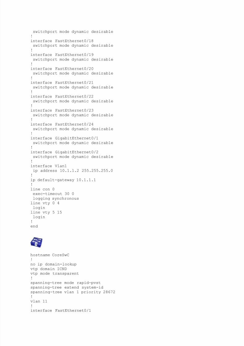
interface Vlan1
ip address 10.1.1.2 255.255.255.0
!
ip default-gateway 10.1.1.1!
line con 0
exec-timeout 30 0
logging synchronous
line vty 0 4
login
line vty 5 15
login
!
end
hostname CoreSwC
!
no ip domain-lookup
vtp domain ICND
vtp mode transparent
!
spanning-tree mode rapid-pvst
spanning-tree extend system-id
spanning-tree vlan 1 priority 28672
!
vlan 11!
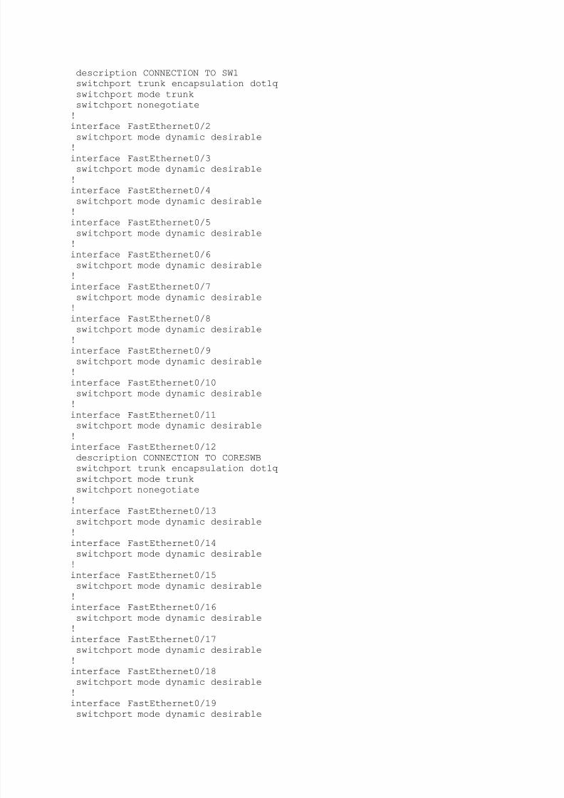
interface FastEthernet0/1
5/12/2018 Configuring Expanded Switched Networks Vlans and Vtp - slidepdf.com
http://slidepdf.com/reader/full/configuring-expanded-switched-networks-vlans-and-vtp
description CONNECTION TO SW1
switchport trunk encapsulation dot1q
switchport mode trunk
switchport nonegotiate
!
interface FastEthernet0/2
switchport mode dynamic desirable!
interface FastEthernet0/3
switchport mode dynamic desirable
!
interface FastEthernet0/4
switchport mode dynamic desirable
!
interface FastEthernet0/5
switchport mode dynamic desirable
!
interface FastEthernet0/6
switchport mode dynamic desirable
!interface FastEthernet0/7
switchport mode dynamic desirable
!
interface FastEthernet0/8
switchport mode dynamic desirable
!
interface FastEthernet0/9
switchport mode dynamic desirable
!
interface FastEthernet0/10
switchport mode dynamic desirable
!
interface FastEthernet0/11switchport mode dynamic desirable
!
interface FastEthernet0/12
description CONNECTION TO CORESWB
switchport trunk encapsulation dot1q
switchport mode trunk
switchport nonegotiate
!
interface FastEthernet0/13
switchport mode dynamic desirable
!
interface FastEthernet0/14
switchport mode dynamic desirable!
interface FastEthernet0/15
switchport mode dynamic desirable
!
interface FastEthernet0/16
switchport mode dynamic desirable
!
interface FastEthernet0/17
switchport mode dynamic desirable
!
interface FastEthernet0/18
switchport mode dynamic desirable
!
interface FastEthernet0/19
switchport mode dynamic desirable
5/12/2018 Configuring Expanded Switched Networks Vlans and Vtp - slidepdf.com
http://slidepdf.com/reader/full/configuring-expanded-switched-networks-vlans-and-vtp
!
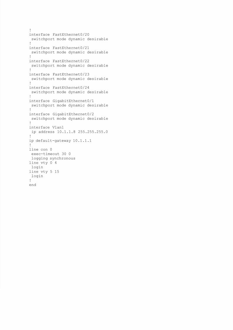
interface FastEthernet0/20
switchport mode dynamic desirable
!
interface FastEthernet0/21
switchport mode dynamic desirable
!interface FastEthernet0/22
switchport mode dynamic desirable
!
interface FastEthernet0/23
switchport mode dynamic desirable
!
interface FastEthernet0/24
switchport mode dynamic desirable
!
interface GigabitEthernet0/1
switchport mode dynamic desirable
!
interface GigabitEthernet0/2switchport mode dynamic desirable
!
interface Vlan1
ip address 10.1.1.8 255.255.255.0
!
ip default-gateway 10.1.1.1
!
line con 0
exec-timeout 30 0
logging synchronous
line vty 0 4
login
line vty 5 15login
!
end


