

1
• A. J. Clark School of Engineering •Department of Civil and Environmental Engineering
Sixth EditionCHAPTER
8
Construction Planning, Equipment, and Methods
EXCAVATORSEXCAVATORS
ByByDr. Ibrahim AssakkafDr. Ibrahim Assakkaf
ENCEENCE 420 420 –– Construction Equipment and MethodsConstruction Equipment and MethodsSpring 2003 Spring 2003
Department of Civil and Environmental EngineeringDepartment of Civil and Environmental EngineeringUniversity of Maryland, College ParkUniversity of Maryland, College Park
CHAPTER 8. EXCAVATORSENCE 420 ©Assakkaf
Slide No. 1
INTRODUCTIONINTRODUCTION
Hydraulic power is Hydraulic power is the key to the the key to the utility of many utility of many
excavators.excavators.

2
CHAPTER 8. EXCAVATORSENCE 420 ©Assakkaf
Slide No. 2
INTRODUCTIONINTRODUCTION
Hydraulic front shovels are used Hydraulic front shovels are used predominantly for hard digging predominantly for hard digging aboveabove track level and for loading track level and for loading haul units.haul units.Hydraulic hoe excavators are used Hydraulic hoe excavators are used primarily to excavate primarily to excavate belowbelow natural natural surface of the ground on which the surface of the ground on which the machine rests. machine rests.
CHAPTER 8. EXCAVATORSENCE 420 ©Assakkaf
Slide No. 3
INTRODUCTIONINTRODUCTION
The loader is a versatile piece of The loader is a versatile piece of equipment designed to excavate at equipment designed to excavate at or above wheel/track level.or above wheel/track level.Unlike a shovel or hoe, to position Unlike a shovel or hoe, to position the bucket to dump, a loader must the bucket to dump, a loader must maneuver and travel with the load.maneuver and travel with the load.They come in various models.They come in various models.

3
CHAPTER 8. EXCAVATORSENCE 420 ©Assakkaf
Slide No. 4
HYDRAULIC EXCAVATORSHYDRAULIC EXCAVATORS
HOE
CHAPTER 8. EXCAVATORSENCE 420 ©Assakkaf
Slide No. 5
WHEEL & TRACK WHEEL & TRACK LOADERSLOADERS
4
CHAPTER 8. EXCAVATORSENCE 420 ©Assakkaf
Slide No. 6
INTRODUCTIONINTRODUCTION
The hydraulic control of machine The hydraulic control of machine components providescomponents provides
Faster cycle times.Outstanding control of attachments.High overall efficiency.Smoothness and ease of operation.Positive control that offers greater accuracy and precision.
CHAPTER 8. EXCAVATORSENCE 420 ©Assakkaf
Slide No. 7
INTRODUCTIONINTRODUCTION•• Machines which make use of hydraulic pressure to Machines which make use of hydraulic pressure to
develop bucket penetration into materials are develop bucket penetration into materials are classified by the digging motion of the bucket.classified by the digging motion of the bucket.
•• The hydraulically controlled boom and stick, to The hydraulically controlled boom and stick, to which the bucket is attached, may be mounted on which the bucket is attached, may be mounted on either a crawler or a wheel tractor base. either a crawler or a wheel tractor base.
•• A downward arc excavator is classified as a "hoe." A downward arc excavator is classified as a "hoe." It develops excavation breakout force by pulling It develops excavation breakout force by pulling the bucket toward the machine and curling the the bucket toward the machine and curling the bucket inward. bucket inward.

5
CHAPTER 8. EXCAVATORSENCE 420 ©Assakkaf
Slide No. 8
INTRODUCTIONINTRODUCTION•• An upward motion unit is known as a "front An upward motion unit is known as a "front
shovel." A shovel develops breakout force by shovel." A shovel develops breakout force by crowding material away from the machine.crowding material away from the machine.
•• The downward swing of a hoe dictates usage for The downward swing of a hoe dictates usage for excavating below the running gear.excavating below the running gear.
•• The boom of a shovel swings upward to load; The boom of a shovel swings upward to load; therefore, the machine requires a material face therefore, the machine requires a material face above the running gear to work against.above the running gear to work against.
CHAPTER 8. EXCAVATORSENCE 420 ©Assakkaf
Slide No. 9
EXCAVATOR PRODUCTIONEXCAVATOR PRODUCTION
Steps for Estimating Production::
1. Obtain the heaped bucket load volume (in lcy) from the manufacturers’ data sheet.
2. Apply a bucket fill factor based on the type of machine and the class material being excavated.
6
CHAPTER 8. EXCAVATORSENCE 420 ©Assakkaf
Slide No. 10
EXCAVATOR PRODUCTIONEXCAVATOR PRODUCTION
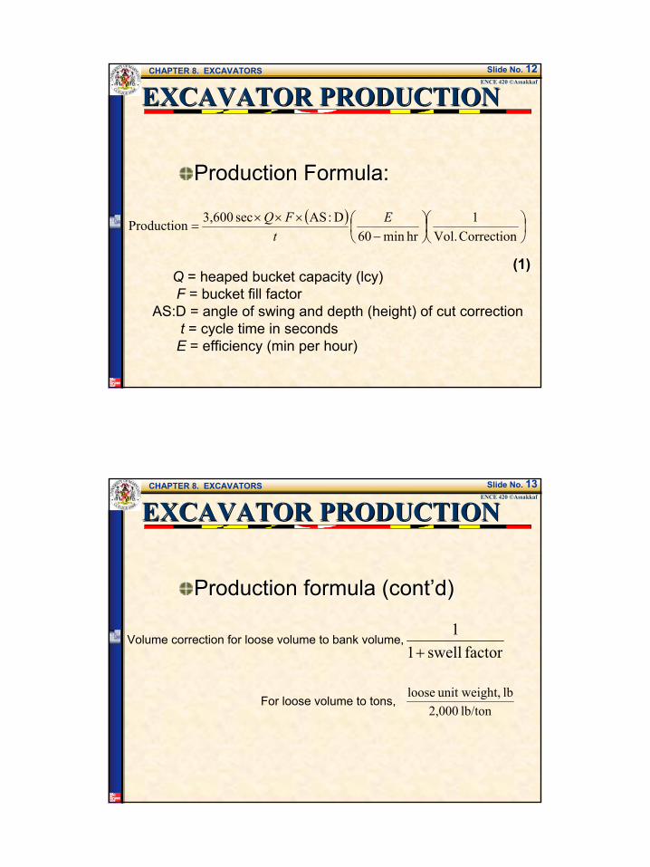
Steps for Estimating Production (cont’d):
3. Estimate a peak cycle time. This a function of machine type and job conditions to angle of swing, depth of height of cut, and in the the case of loaders, travel distance.
CHAPTER 8. EXCAVATORSENCE 420 ©Assakkaf
Slide No. 11
Steps for Estimating Production (cont’d):
4. Apply an efficiency factor.5. Conform the production units to
the desired volume or weight (lcyto bcy or tons).
6. Calculate the production rate.
EXCAVATOR PRODUCTIONEXCAVATOR PRODUCTION
7
CHAPTER 8. EXCAVATORSENCE 420 ©Assakkaf
Slide No. 12
EXCAVATOR PRODUCTIONEXCAVATOR PRODUCTION
Production Formula:Production Formula:
( )
−×××
=Correction Vol.
1hrmin60
D:AS sec 3,600Production EtFQ
Q = heaped bucket capacity (lcy)F = bucket fill factor
AS:D = angle of swing and depth (height) of cut correctiont = cycle time in secondsE = efficiency (min per hour)
(1)
CHAPTER 8. EXCAVATORSENCE 420 ©Assakkaf
Slide No. 13
EXCAVATOR PRODUCTIONEXCAVATOR PRODUCTION
Production formula (cont’d)Production formula (cont’d)
factorswell11
+
For loose volume to tons,lb/ton 2,000
lb t,unit weigh loose
Volume correction for loose volume to bank volume,

8
CHAPTER 8. EXCAVATORSENCE 420 ©Assakkaf
Slide No. 14
FRONT SHOVELSFRONT SHOVELS
Front shovels are used Front shovels are used predominately for hard digging predominately for hard digging above track level, and loading above track level, and loading haul units.haul units.The loading of shot rock would The loading of shot rock would be a typical application.be a typical application.
CHAPTER 8. EXCAVATORSENCE 420 ©Assakkaf
Slide No. 15
FRONT SHOVELSFRONT SHOVELS
Boom
Stick
Bucket
9
CHAPTER 8. EXCAVATORSENCE 420 ©Assakkaf
Slide No. 16
FRONT SHOVELSFRONT SHOVELS
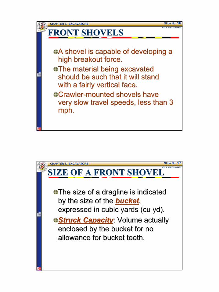
A shovel is capable of developing a A shovel is capable of developing a high breakout force.high breakout force.The material being excavated The material being excavated should be such that it will stand should be such that it will stand with a fairly vertical face.with a fairly vertical face.CrawlerCrawler--mounted shovels have mounted shovels have very slow travel speeds, less than 3 very slow travel speeds, less than 3 mph.mph.
CHAPTER 8. EXCAVATORSENCE 420 ©Assakkaf
Slide No. 17
SIZE OF A FRONT SHOVELSIZE OF A FRONT SHOVEL
The size of a dragline is indicated The size of a dragline is indicated by the size of the by the size of the bucketbucket, , expressed in cubic yards (cu yd).expressed in cubic yards (cu yd).Struck CapacityStruck Capacity: Volume actually : Volume actually enclosed by the bucket for no enclosed by the bucket for no allowance for bucket teeth.allowance for bucket teeth.
10
CHAPTER 8. EXCAVATORSENCE 420 ©Assakkaf
Slide No. 18
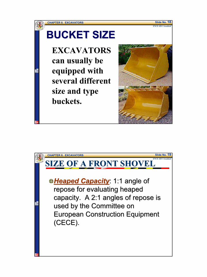
BUCKET SIZEBUCKET SIZEEXCAVATORS can usually be equipped with several different size and type buckets.
CHAPTER 8. EXCAVATORSENCE 420 ©Assakkaf
Slide No. 19
SIZE OF A FRONT SHOVELSIZE OF A FRONT SHOVEL
Heaped CapacityHeaped Capacity: 1:1 angle of : 1:1 angle of repose for evaluating heaped repose for evaluating heaped capacity. A 2:1 angles of repose is capacity. A 2:1 angles of repose is used by the Committee on used by the Committee on European Construction Equipment European Construction Equipment ((CECECECE).).

11
CHAPTER 8. EXCAVATORSENCE 420 ©Assakkaf
Slide No. 20
SIZE OF A FRONT SHOVELSIZE OF A FRONT SHOVEL
Fill FactorFill Factor: Rated heaped capacities : Rated heaped capacities represent a net section bucket volume; represent a net section bucket volume; therefore, they must be corrected to therefore, they must be corrected to average bucket load based on the material average bucket load based on the material being handled. Fill factors are being handled. Fill factors are percentages which, when multiplied by percentages which, when multiplied by rated heaped capacity, adjust the volume rated heaped capacity, adjust the volume by accounting for how the specific material by accounting for how the specific material will load into the bucket (see the following will load into the bucket (see the following table, Table 5, or Table 8.1 of Textbook).table, Table 5, or Table 8.1 of Textbook).
CHAPTER 8. EXCAVATORSENCE 420 ©Assakkaf
Slide No. 21
SIZE OF A FRONT SHOVELSIZE OF A FRONT SHOVEL
Table 1. Fill Factors for Front Shovel Buckets (Caterpillar Inc.) Material Fill Factor* (%)
Bank clay; earth 100 to 110 Rock-earth mixture 105 to 115 Rock-poorly blasted 85 to 100 Rock-well blasted 100 to 110 Shale; sandstone-standing bank 85 to 100 * Percent of heaped bucket capacity

12
CHAPTER 8. EXCAVATORSENCE 420 ©Assakkaf
Slide No. 22
SHOVEL PRODUCTIONSHOVEL PRODUCTION
Typical cycle element times under Typical cycle element times under average conditions, for 3 to 5average conditions, for 3 to 5--cucu--yd yd shovels, will beshovels, will be
Load bucket 7-9 secSwing with load 4-6 secDump load 2-4 secReturn swing 4-5 sec
CHAPTER 8. EXCAVATORSENCE 420 ©Assakkaf
Slide No. 23
SHOVEL PRODUCTIONSHOVEL PRODUCTION
Actual production of a shovel is Actual production of a shovel is affected by the following factors:affected by the following factors:
Class of materialHeight of cutAngle of swingSize of hauling unitsOperator skillPhysical condition of the shovel
Production efficiency ranges from 30 to 45 min per hour
13
CHAPTER 8. EXCAVATORSENCE 420 ©Assakkaf
Slide No. 24
EFFECT OF THE HEIGHT OF CUT EFFECT OF THE HEIGHT OF CUT AND SWING ANGLE ON SHOVEL AND SWING ANGLE ON SHOVEL PRODUCTIONPRODUCTION
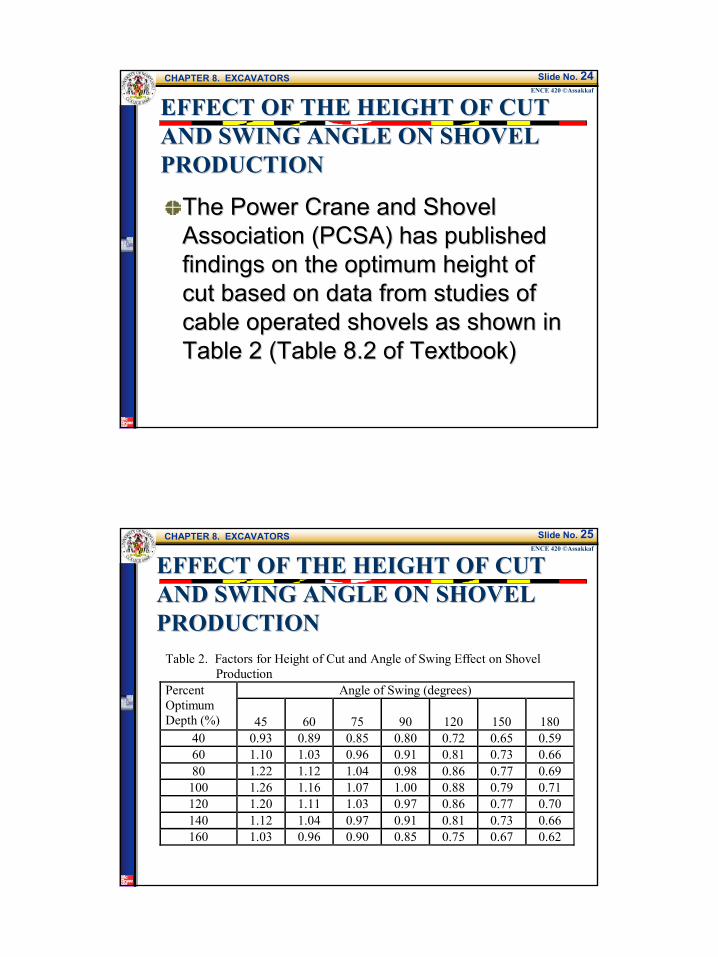
The Power Crane and Shovel The Power Crane and Shovel Association (Association (PCSAPCSA) has published ) has published findings on the optimum height of findings on the optimum height of cut based on data from studies of cut based on data from studies of cable operated shovels as shown in cable operated shovels as shown in Table 2 (Table 8.2 of Textbook)Table 2 (Table 8.2 of Textbook)
CHAPTER 8. EXCAVATORSENCE 420 ©Assakkaf
Slide No. 25
EFFECT OF THE HEIGHT OF CUT EFFECT OF THE HEIGHT OF CUT AND SWING ANGLE ON SHOVEL AND SWING ANGLE ON SHOVEL PRODUCTIONPRODUCTION
Table 2. Factors for Height of Cut and Angle of Swing Effect on Shovel Production
Angle of Swing (degrees) Percent Optimum Depth (%)
45
60
75
90
120
150
180
40 0.93 0.89 0.85 0.80 0.72 0.65 0.59 60 1.10 1.03 0.96 0.91 0.81 0.73 0.66 80 1.22 1.12 1.04 0.98 0.86 0.77 0.69
100 1.26 1.16 1.07 1.00 0.88 0.79 0.71 120 1.20 1.11 1.03 0.97 0.86 0.77 0.70 140 1.12 1.04 0.97 0.91 0.81 0.73 0.66 160 1.03 0.96 0.90 0.85 0.75 0.67 0.62

14
CHAPTER 8. EXCAVATORSENCE 420 ©Assakkaf
Slide No. 26
SWING ANGLE?
90°
30°
swing angle of 30-60º
60°
CHAPTER 8. EXCAVATORSENCE 420 ©Assakkaf
Slide No. 27
EFFECT OF THE HEIGHT OF CUT EFFECT OF THE HEIGHT OF CUT AND SWING ANGLE ON SHOVEL AND SWING ANGLE ON SHOVEL PRODUCTIONPRODUCTION
The percent of optimum height of The percent of optimum height of cut, in the table, is obtained by cut, in the table, is obtained by dividing the the actual height of cut dividing the the actual height of cut by the optimum height for the given by the optimum height for the given material and bucket, and then material and bucket, and then multiplying the result by 100.multiplying the result by 100.
15
CHAPTER 8. EXCAVATORSENCE 420 ©Assakkaf
Slide No. 28
EFFECT OF THE HEIGHT OF CUT EFFECT OF THE HEIGHT OF CUT AND SWING ANGLE ON SHOVEL AND SWING ANGLE ON SHOVEL PRODUCTIONPRODUCTION
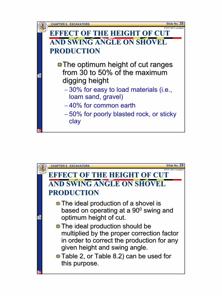
The optimum height of cut ranges The optimum height of cut ranges from 30 to 50% of the maximum from 30 to 50% of the maximum digging heightdigging height−30% for easy to load materials (i.e.,
loam sand, gravel)−40% for common earth−50% for poorly blasted rock, or sticky
clay
CHAPTER 8. EXCAVATORSENCE 420 ©Assakkaf
Slide No. 29
EFFECT OF THE HEIGHT OF CUT EFFECT OF THE HEIGHT OF CUT AND SWING ANGLE ON SHOVEL AND SWING ANGLE ON SHOVEL PRODUCTIONPRODUCTION
The ideal production of a shovel is The ideal production of a shovel is based on operating at a 90based on operating at a 9000 swing and swing and optimum height of cut.optimum height of cut.The ideal production should be The ideal production should be multiplied by the proper correction factor multiplied by the proper correction factor in order to correct the production for any in order to correct the production for any given height and swing angle.given height and swing angle.Table 2, or Table 8.2) can be used for Table 2, or Table 8.2) can be used for this purpose.this purpose.
16
CHAPTER 8. EXCAVATORSENCE 420 ©Assakkaf
Slide No. 30
Example 1Example 1
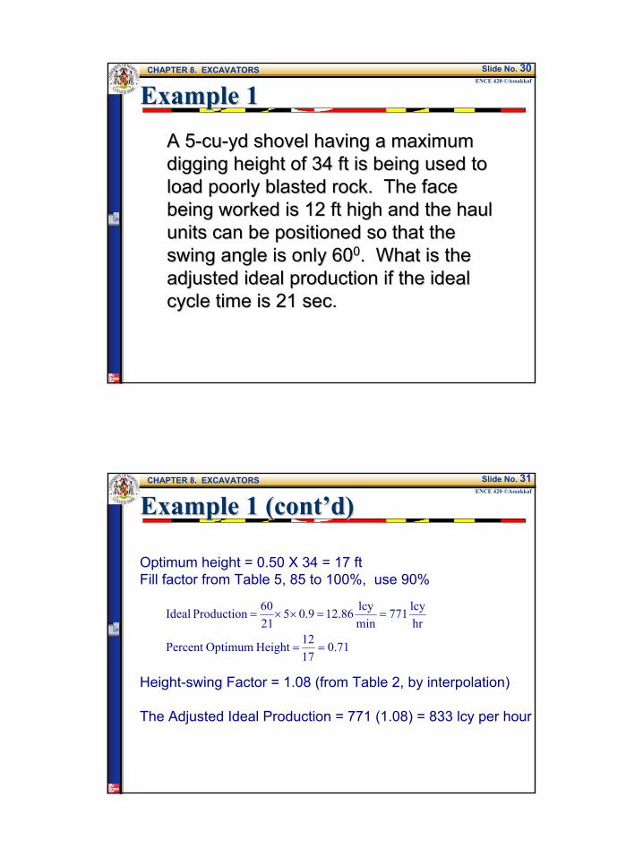
A 5A 5--cucu--yd shovel having a maximum yd shovel having a maximum digging height of 34 ft is being used to digging height of 34 ft is being used to load poorly blasted rock. The face load poorly blasted rock. The face being worked is 12 ft high and the haul being worked is 12 ft high and the haul units can be positioned so that the units can be positioned so that the swing angle is only 60swing angle is only 6000. What is the . What is the adjusted ideal production if the ideal adjusted ideal production if the ideal cycle time is 21 sec.cycle time is 21 sec.
CHAPTER 8. EXCAVATORSENCE 420 ©Assakkaf
Slide No. 31
Example 1 (cont’d)Example 1 (cont’d)
Optimum height = 0.50 X 34 = 17 ftFill factor from Table 5, 85 to 100%, use 90%
Height-swing Factor = 1.08 (from Table 2, by interpolation)
The Adjusted Ideal Production = 771 (1.08) = 833 lcy per hour
71.01712 Height OptimumPercent
hrlcy 771
minlcy86.129.05
2160 Production Ideal
==
==××=

17
CHAPTER 8. EXCAVATORSENCE 420 ©Assakkaf
Slide No. 32
Example 2Example 2
A 3A 3--cucu--yd shovel, having a maximum yd shovel, having a maximum digging height of 30 ft, will be used on a digging height of 30 ft, will be used on a highway project to excavate wellhighway project to excavate well--blasted rock. The average face height blasted rock. The average face height is expected to be 22 ft. Most of the cut is expected to be 22 ft. Most of the cut will require a 140will require a 14000 swing of the shovel in swing of the shovel in order to load the haul units. Determine order to load the haul units. Determine the estimated production in cubic yards the estimated production in cubic yards bank measure.bank measure.
CHAPTER 8. EXCAVATORSENCE 420 ©Assakkaf
Slide No. 33
Example 2 (cont’d)Example 2 (cont’d)
Optimum height = 0.50 X 30 = 15 ftFill Factor from Table 1, (100 to 110%), use 100%Cycle Time = Load + Swing Loaded + Dump + Swing empty
= 9 + 4 + 4 + 4 = 21 sec = 0.35 min
%14747.11522 Height OptimumPercent
hrlcy5140.13
0.3560 Production Ideal
===
=××=
18
CHAPTER 8. EXCAVATORSENCE 420 ©Assakkaf
Slide No. 34
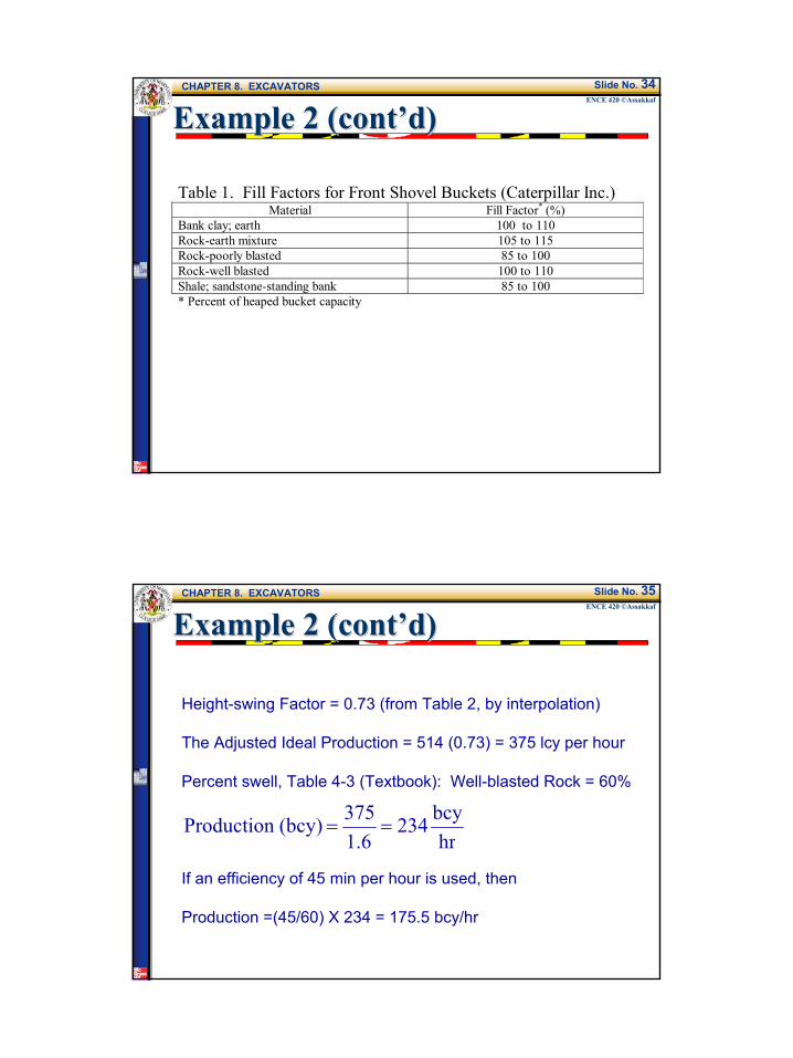
Example 2 (cont’d)Example 2 (cont’d)
Table 1. Fill Factors for Front Shovel Buckets (Caterpillar Inc.) Material Fill Factor* (%)
Bank clay; earth 100 to 110 Rock-earth mixture 105 to 115 Rock-poorly blasted 85 to 100 Rock-well blasted 100 to 110 Shale; sandstone-standing bank 85 to 100 * Percent of heaped bucket capacity
CHAPTER 8. EXCAVATORSENCE 420 ©Assakkaf
Slide No. 35
Example 2 (cont’d)Example 2 (cont’d)
Height-swing Factor = 0.73 (from Table 2, by interpolation)
The Adjusted Ideal Production = 514 (0.73) = 375 lcy per hour
Percent swell, Table 4-3 (Textbook): Well-blasted Rock = 60%
If an efficiency of 45 min per hour is used, then
Production =(45/60) X 234 = 175.5 bcy/hr
hrbcy234
1.6375(bcy) Production ==

19
CHAPTER 8. EXCAVATORSENCE 420 ©Assakkaf
Slide No. 36
Example 2 (cont’d)Example 2 (cont’d)Table 2. Factors for Height of Cut and Angle of Swing Effect on Shovel Production
Angle of Swing (degrees) Percent Optimum Depth (%)
45
60
75
90
120
150
180
40 0.93 0.89 0.85 0.80 0.72 0.65 0.59 60 1.10 1.03 0.96 0.91 0.81 0.73 0.66 80 1.22 1.12 1.04 0.98 0.86 0.77 0.69
100 1.26 1.16 1.07 1.00 0.88 0.79 0.71 120 1.20 1.11 1.03 0.97 0.86 0.77 0.70 140 1.12 1.04 0.97 0.91 0.81 0.73 0.66 160 1.03 0.96 0.90 0.85 0.75 0.67 0.62
CHAPTER 8. EXCAVATORSENCE 420 ©Assakkaf
Slide No. 37
Example 2 (cont’d)Example 2 (cont’d)
Bank Loose weight weight
Percent SwellMaterial lb/cu yd kg/m3 lb/cu yd kg/m3 swell factor
Clay,dry 2,700 1,600 2,000 1,185 35 0.74Clay, wet 3,000 1,780 2,200 1,305 35 0.74Earth, dry 2,800 1,660 2,240 1,325 25 0.80Earth, wet 3,200 1,895 2,580 1,528 25 0.80Earth and gravel 3,200 1,895 2,600 1,575 20 0.83Gravel, dry 2,800 1,660 2,490 1,475 12 0.89Gravel, wet 3,400 2,020 2,980 1,765 14 0.88Limestone 4,400 2,610 2,750 1,630 60 0.63Rock, well blasted 4,200 2,490 2,640 1,565 60 0.63Sand, dry 2,600 1,542 2,260 1,340 15 0.87Sand, wet 2,700 1,600 2,360 1,400 15 0.87Shale 3,500 2,075 2,480 1,470 40 0.71
20
CHAPTER 8. EXCAVATORSENCE 420 ©Assakkaf
Slide No. 38
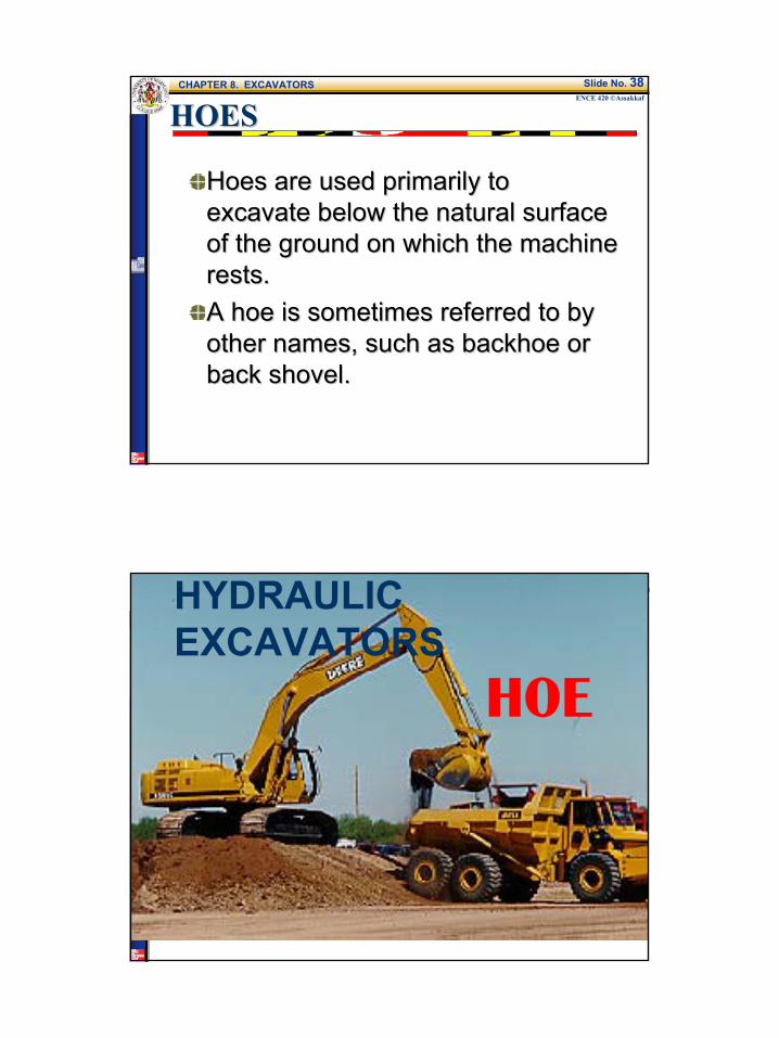
HOESHOES
Hoes are used primarily to Hoes are used primarily to excavate below the natural surface excavate below the natural surface of the ground on which the machine of the ground on which the machine rests.rests.A hoe is sometimes referred to by A hoe is sometimes referred to by other names, such as backhoe or other names, such as backhoe or back shovel. back shovel.
CHAPTER 8. EXCAVATORSENCE 420 ©Assakkaf
Slide No. 39HYDRAULIC EXCAVATORS
HOE
21
CHAPTER 8. EXCAVATORSENCE 420 ©Assakkaf
Slide No. 40
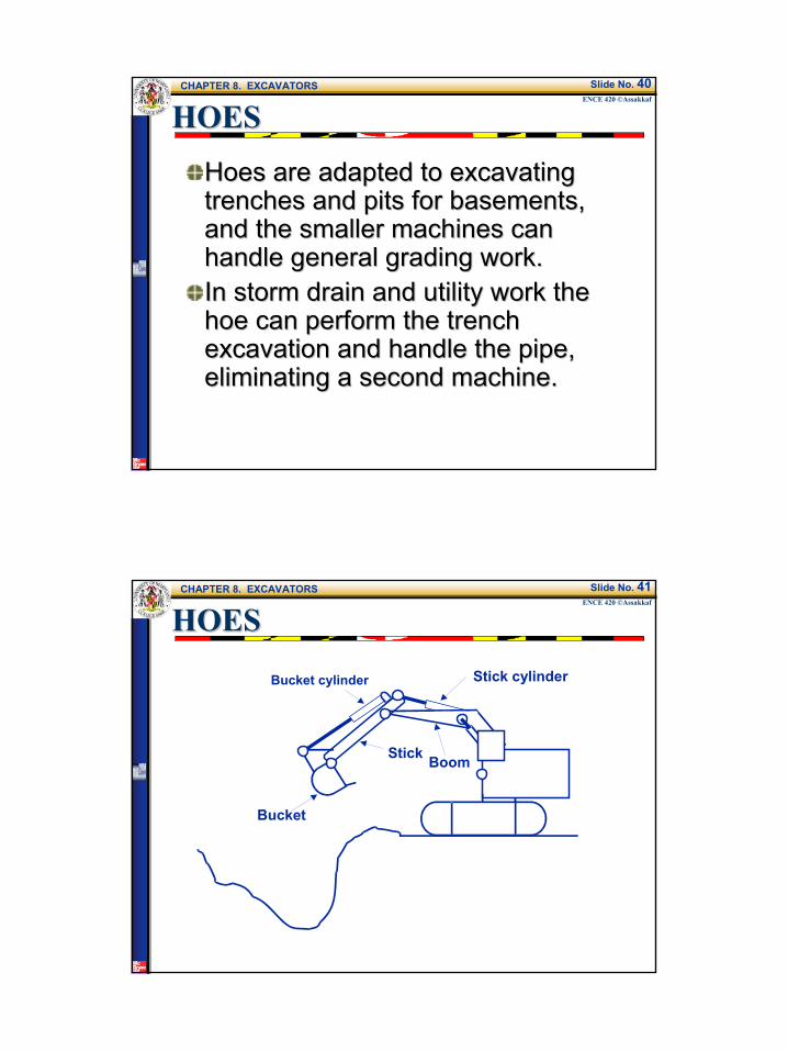
HOESHOES
Hoes are adapted to excavating Hoes are adapted to excavating trenches and pits for basements, trenches and pits for basements, and the smaller machines can and the smaller machines can handle general grading work.handle general grading work.In storm drain and utility work the In storm drain and utility work the hoe can perform the trench hoe can perform the trench excavation and handle the pipe, excavation and handle the pipe, eliminating a second machine.eliminating a second machine.
CHAPTER 8. EXCAVATORSENCE 420 ©Assakkaf
Slide No. 41
HOESHOES
BoomStick
Bucket
Stick cylinderBucket cylinder
22
CHAPTER 8. EXCAVATORSENCE 420 ©Assakkaf
Slide No. 42
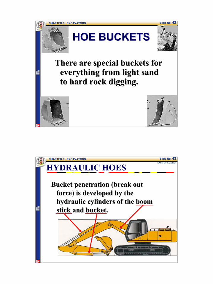
HOE BUCKETSHOE BUCKETS
There are special buckets for There are special buckets for everything from light sand everything from light sand to hard rock digging.to hard rock digging.
CHAPTER 8. EXCAVATORSENCE 420 ©Assakkaf
Slide No. 43
Bucket penetration (break out Bucket penetration (break out force) is developed by the force) is developed by the hydraulic cylinders of the boom hydraulic cylinders of the boom stick and bucket. stick and bucket.
HYDRAULIC HOES
23
CHAPTER 8. EXCAVATORSENCE 420 ©Assakkaf
Slide No. 44
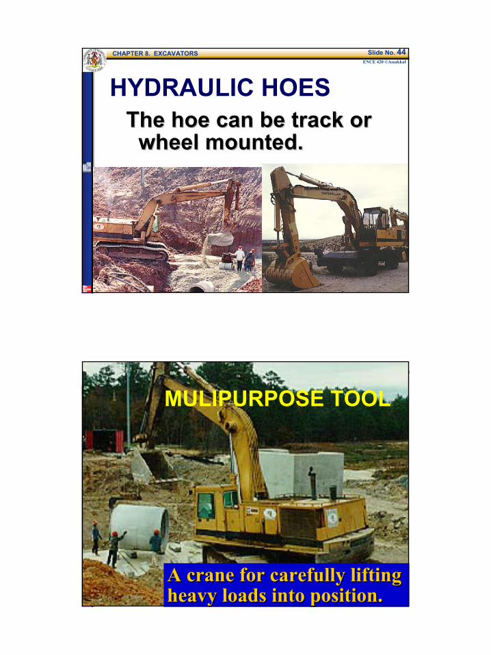
HYDRAULIC HOESThe hoe can be track or The hoe can be track or
wheel mounted.wheel mounted.
CHAPTER 8. EXCAVATORSENCE 420 ©Assakkaf
Slide No. 45
MULIPURPOSE TOOL
A crane for carefully lifting A crane for carefully lifting heavy loads into position.heavy loads into position.
24
CHAPTER 8. EXCAVATORSENCE 420 ©Assakkaf
Slide No. 46
HYDRAULIC HOESHYDRAULIC HOES
These machines offer These machines offer precision and efficiency.precision and efficiency.The average (first owner) The average (first owner) life is about seven years.life is about seven years.
CHAPTER 8. EXCAVATORSENCE 420 ©Assakkaf
Slide No. 47
PRODUCTION ESTIMATINGPRODUCTION ESTIMATING
STEP 1: Bucket size (LCY)Many different size buckets will fit Many different size buckets will fit
the same machine. Interested in the same machine. Interested in heaped capacity.heaped capacity.Heaped capacity ratings for hoe buckets assume a 1:1 material angle of repose.
25
CHAPTER 8. EXCAVATORSENCE 420 ©Assakkaf
Slide No. 48
PRODUCTION ESTIMATINGPRODUCTION ESTIMATING
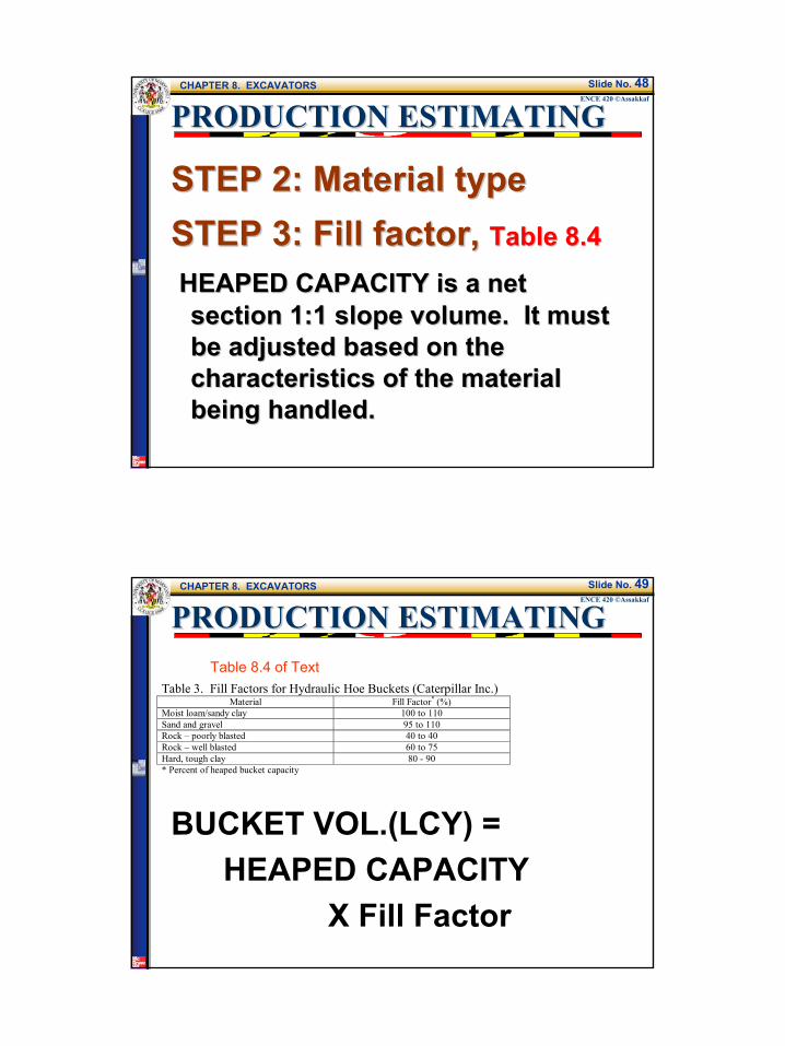
STEP 2: Material typeSTEP 2: Material typeSTEP 3: Fill factor,STEP 3: Fill factor, Table 8.4Table 8.4
HEAPED CAPACITY is a net HEAPED CAPACITY is a net section 1:1 slope volume. It must section 1:1 slope volume. It must be adjusted based on the be adjusted based on the characteristics of the material characteristics of the material being handled.being handled.
CHAPTER 8. EXCAVATORSENCE 420 ©Assakkaf
Slide No. 49
PRODUCTION ESTIMATINGPRODUCTION ESTIMATING
Table 3. Fill Factors for Hydraulic Hoe Buckets (Caterpillar Inc.) Material Fill Factor* (%)
Moist loam/sandy clay 100 to 110 Sand and gravel 95 to 110 Rock – poorly blasted 40 to 40 Rock – well blasted 60 to 75 Hard, tough clay 80 - 90 * Percent of heaped bucket capacity
Table 8.4 of Text
BUCKET VOL.(LCY) = HEAPED CAPACITY
X Fill Factor
26
CHAPTER 8. EXCAVATORSENCE 420 ©Assakkaf
Slide No. 50
PRODUCTION ESTIMATINGPRODUCTION ESTIMATING
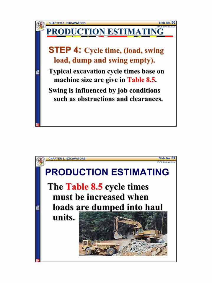
STEP 4STEP 4: : Cycle time, (load, swing Cycle time, (load, swing load, dump and swing empty).load, dump and swing empty).
Typical excavation cycle times base on Typical excavation cycle times base on machine size are give in machine size are give in Table 8.5Table 8.5. .
Swing is influenced by job conditions Swing is influenced by job conditions such as obstructions and clearances.such as obstructions and clearances.
CHAPTER 8. EXCAVATORSENCE 420 ©Assakkaf
Slide No. 51
PRODUCTION ESTIMATINGThe The Table 8.5Table 8.5 cycle times cycle times
must be increased when must be increased when loads are dumped into haul loads are dumped into haul units.units.

27
CHAPTER 8. EXCAVATORSENCE 420 ©Assakkaf
Slide No. 52
CYCLE TIMESmall machines Small machines
swing faster than swing faster than large ones. large ones.
CHAPTER 8. EXCAVATORSENCE 420 ©Assakkaf
Slide No. 53
SWING ANGLE?
90°
30°
Table 8.5 cycle times are based on aswing angle of 30-60º
60°

28
CHAPTER 8. EXCAVATORSENCE 420 ©Assakkaf
Slide No. 54
PRODUCTION ESTIMATING
STEP 5STEP 5: : Check depth of cutCheck depth of cutTypical cycle times are for depth of Typical cycle times are for depth of
cut between 40cut between 40--60% of maximum 60% of maximum digging depth.digging depth.
Check manufacturer's data.Check manufacturer's data.Table 8.3Table 8.3 gives typical information gives typical information
based on hoe size.based on hoe size.
CHAPTER 8. EXCAVATORSENCE 420 ©Assakkaf
Slide No. 55
STEP 5:STEP 5:Manufacturer's Manufacturer's data.data.
DEPTH OF CUT
DC
C. Maximumdig depth
D. Dig depth,level bottom

29
CHAPTER 8. EXCAVATORSENCE 420 ©Assakkaf
Slide No. 56
PRODUCTION ESTIMATINGPRODUCTION ESTIMATINGSTEP 6:STEP 6: Check Check
loading heightloading heightDoes the selected Does the selected
hoe have the hoe have the reach capability reach capability to load the haul to load the haul unit. unit. Table 8.3Table 8.3
E
CHAPTER 8. EXCAVATORSENCE 420 ©Assakkaf
Slide No. 57
PRODUCTION ESTIMATINGPRODUCTION ESTIMATING
STEP 7:STEP 7: Efficiency factorEfficiency factorThe three primary conditions that The three primary conditions that
control the efficiency of excavator control the efficiency of excavator loading operations are:loading operations are:
BunchingOperator efficiencyEquipment availability
30
CHAPTER 8. EXCAVATORSENCE 420 ©Assakkaf
Slide No. 58
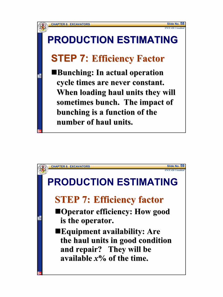
PRODUCTION ESTIMATINGPRODUCTION ESTIMATING
STEP 7:STEP 7: Efficiency FactorEfficiency FactorBunching: In actual operation Bunching: In actual operation cycle times are never constant. cycle times are never constant. When loading haul units they will When loading haul units they will sometimes bunch. The impact of sometimes bunch. The impact of bunching is a function of the bunching is a function of the number of haul units.number of haul units.
CHAPTER 8. EXCAVATORSENCE 420 ©Assakkaf
Slide No. 59
PRODUCTION ESTIMATING
STEP 7:STEP 7: Efficiency factorEfficiency factorOperator efficiency: How good Operator efficiency: How good is the operator.is the operator.Equipment availability: Are Equipment availability: Are the haul units in good condition the haul units in good condition and repair? They will be and repair? They will be available available xx% of the time.% of the time.
31
CHAPTER 8. EXCAVATORSENCE 420 ©Assakkaf
Slide No. 60
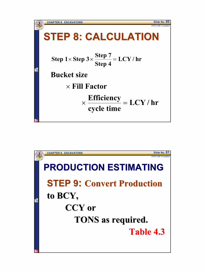
STEP 8: CALCULATIONSTEP 8: CALCULATION
Step 1 Step 3 Step 7Step 4
LCY / hr× × =
Bucket sizeFill Factor
Efficiencycycle time
LCY / hr
×
× =
CHAPTER 8. EXCAVATORSENCE 420 ©Assakkaf
Slide No. 61
STEP 9STEP 9: : Convert ProductionConvert Productionto BCY,to BCY,
CCY orCCY orTONS as required.TONS as required.
Table 4.3Table 4.3
PRODUCTION ESTIMATINGPRODUCTION ESTIMATING
32
CHAPTER 8. EXCAVATORSENCE 420 ©Assakkaf
Slide No. 62
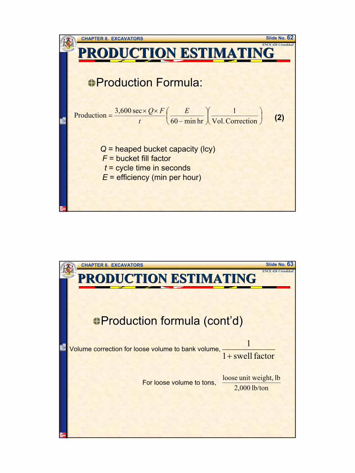
PRODUCTION ESTIMATINGPRODUCTION ESTIMATING
Production Formula:Production Formula:
−××
=Correction Vol.
1hrmin60
sec 3,600Production Et
FQ
Q = heaped bucket capacity (lcy)F = bucket fill factort = cycle time in secondsE = efficiency (min per hour)
(2)
CHAPTER 8. EXCAVATORSENCE 420 ©Assakkaf
Slide No. 63
Production formula (cont’d)Production formula (cont’d)
factorswell11
+
For loose volume to tons,lb/ton 2,000
lb t,unit weigh loose
Volume correction for loose volume to bank volume,
PRODUCTION ESTIMATINGPRODUCTION ESTIMATING
33
CHAPTER 8. EXCAVATORSENCE 420 ©Assakkaf
Slide No. 64
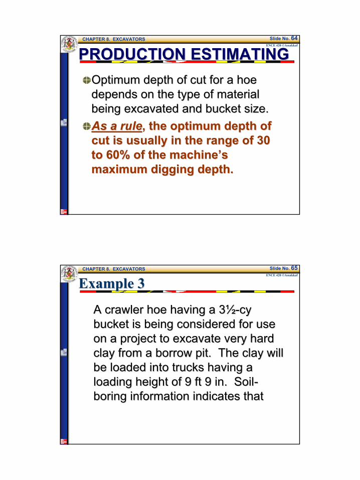
PRODUCTION ESTIMATINGPRODUCTION ESTIMATINGOptimum depth of cut for a hoe Optimum depth of cut for a hoe depends on the type of material depends on the type of material being excavated and bucket size.being excavated and bucket size.As a ruleAs a rule, the optimum depth of , the optimum depth of cut is usually in the range of 30 cut is usually in the range of 30 to 60% of the machine’s to 60% of the machine’s maximum digging depth.maximum digging depth.
CHAPTER 8. EXCAVATORSENCE 420 ©Assakkaf
Slide No. 65
Example 3Example 3
A crawler hoe having a 3A crawler hoe having a 3½½--cy cy bucket is being considered for use bucket is being considered for use on a project to excavate very hard on a project to excavate very hard clay from a borrow pit. The clay will clay from a borrow pit. The clay will be loaded into trucks having a be loaded into trucks having a loading height of 9 ft 9 in. Soilloading height of 9 ft 9 in. Soil--boring information indicates thatboring information indicates that

34
CHAPTER 8. EXCAVATORSENCE 420 ©Assakkaf
Slide No. 66
Example 3 (cont’d)Example 3 (cont’d)
below 8 ft, the material changes to below 8 ft, the material changes to an unacceptable silt material. What an unacceptable silt material. What is the estimated production of the is the estimated production of the hoe in cubic yards bank measure, if hoe in cubic yards bank measure, if the efficiency factor is equal to a the efficiency factor is equal to a 5050--min hour?min hour?
CHAPTER 8. EXCAVATORSENCE 420 ©Assakkaf
Slide No. 67
Example 3 (cont’d)Example 3 (cont’d)
Step 1:Step 1:Size of bucket = 3½ cy
Step 2:Step 2:Bucket fill factor, Table 3 (Table 8.4 Text) gives 80 to 90%.Use average:
%852
9080=
+
35
CHAPTER 8. EXCAVATORSENCE 420 ©Assakkaf
Slide No. 68
Example 3 (cont’d)Example 3 (cont’d)
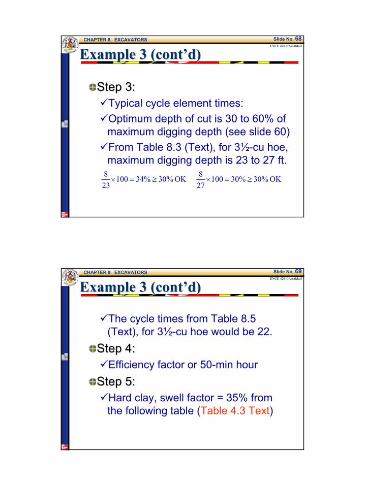
Step 3:Step 3:Typical cycle element times:Optimum depth of cut is 30 to 60% of maximum digging depth (see slide 60)From Table 8.3 (Text), for 3½-cu hoe, maximum digging depth is 23 to 27 ft.
OK %30%30100278OK %30%34100
238
≥=×≥=×
CHAPTER 8. EXCAVATORSENCE 420 ©Assakkaf
Slide No. 69
Example 3 (cont’d)Example 3 (cont’d)
The cycle times from Table 8.5 (Text), for 3½-cu hoe would be 22.
Step 4:Step 4:Efficiency factor or 50-min hour
Step 5:Step 5:Hard clay, swell factor = 35% from the following table (Table 4.3 Text)
36
CHAPTER 8. EXCAVATORSENCE 420 ©Assakkaf
Slide No. 70
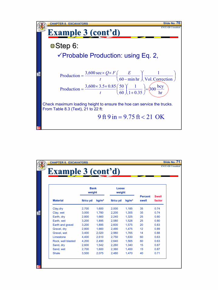
Example 3 (cont’d)Example 3 (cont’d)Step 6:Step 6:
Probable Production: using Eq. 2,
hrbcy 300
0.3511
605085.05.3 3,600Production
Correction Vol.1
hrmin60 sec 3,600Production
=
+
××
=
−××
=
t
Et
FQ
Check maximum loading height to ensure the hoe can service the trucks.From Table 8.3 (Text), 21 to 22 ft:
OK 21 ft 9.75in 9ft 9 <=
CHAPTER 8. EXCAVATORSENCE 420 ©Assakkaf
Slide No. 71
Example 3 (cont’d)Example 3 (cont’d)
Bank Loose weight weight
Percent SwellMaterial lb/cu yd kg/m3 lb/cu yd kg/m3 swell factor
Clay,dry 2,700 1,600 2,000 1,185 35 0.74Clay, wet 3,000 1,780 2,200 1,305 35 0.74Earth, dry 2,800 1,660 2,240 1,325 25 0.80Earth, wet 3,200 1,895 2,580 1,528 25 0.80Earth and gravel 3,200 1,895 2,600 1,575 20 0.83Gravel, dry 2,800 1,660 2,490 1,475 12 0.89Gravel, wet 3,400 2,020 2,980 1,765 14 0.88Limestone 4,400 2,610 2,750 1,630 60 0.63Rock, well blasted 4,200 2,490 2,640 1,565 60 0.63Sand, dry 2,600 1,542 2,260 1,340 15 0.87Sand, wet 2,700 1,600 2,360 1,400 15 0.87Shale 3,500 2,075 2,480 1,470 40 0.71

37
CHAPTER 8. EXCAVATORSENCE 420 ©Assakkaf
Slide No. 72
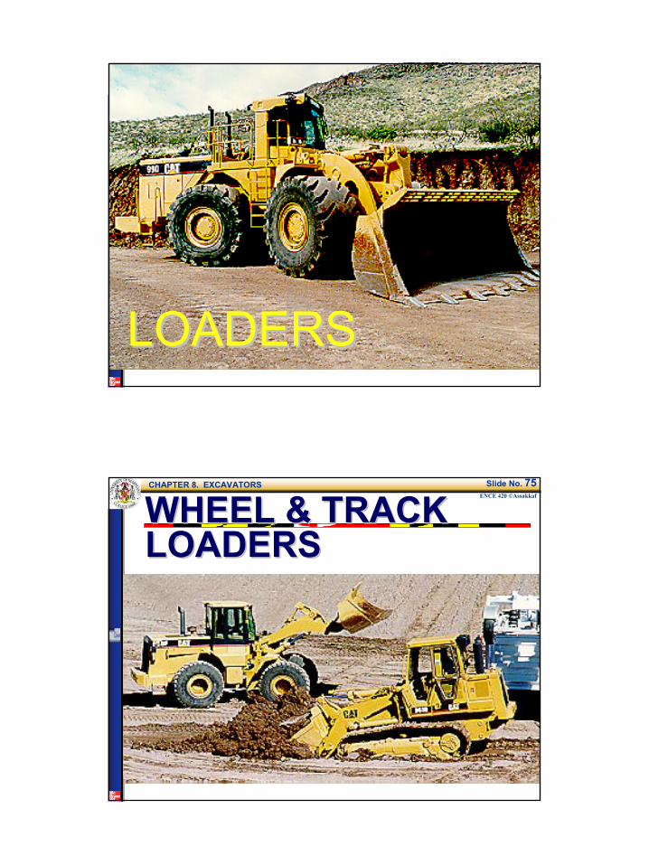
LOADERSLOADERS
Loaders are used extensively in Loaders are used extensively in construction work to handle and construction work to handle and transport bulk material, such as transport bulk material, such as earth and rock, to load trucks, to earth and rock, to load trucks, to excavate earth, and to charge excavate earth, and to charge aggregate bins at asphalt and aggregate bins at asphalt and concrete plants.concrete plants.
CHAPTER 8. EXCAVATORSENCE 420 ©Assakkaf
Slide No. 73
LOADERSLOADERS
There are basically two types of There are basically two types of loaders:loaders:
The crawler-tractor-mounted type, and The wheel-tractor-mounted type.
38
CHAPTER 8. EXCAVATORSENCE 420 ©Assakkaf
Slide No. 74
LOADERSLOADERS
CHAPTER 8. EXCAVATORSENCE 420 ©Assakkaf
Slide No. 75
WHEEL & TRACK WHEEL & TRACK LOADERSLOADERS

39
CHAPTER 8. EXCAVATORSENCE 420 ©Assakkaf
Slide No. 76
LOADERSLOADERSPRODUCTIONPRODUCTION
CHAPTER 8. EXCAVATORSENCE 420 ©Assakkaf
Slide No. 77
LOADER PRODUCTIONLOADER PRODUCTION

40
CHAPTER 8. EXCAVATORSENCE 420 ©Assakkaf
Slide No. 78
LOADER PRODUCTIONLOADER PRODUCTION
CHAPTER 8. EXCAVATORSENCE 420 ©Assakkaf
Slide No. 79
TRENCHING MACHINESTRENCHING MACHINES
The term "trenching machine" applies to The term "trenching machine" applies to the wheelthe wheel-- and ladder type machines.and ladder type machines.These machines are satisfactory for These machines are satisfactory for digging utility trenches for water, gas, digging utility trenches for water, gas, and oil pipelines; shoulder drains on and oil pipelines; shoulder drains on highways; drainage ditches; and sewers highways; drainage ditches; and sewers where the job and soil conditions are where the job and soil conditions are such that they may be used. such that they may be used.
41
CHAPTER 8. EXCAVATORSENCE 420 ©Assakkaf
Slide No. 80
TRENCHING MACHINESTRENCHING MACHINES
They provide relatively fast digging, They provide relatively fast digging, with positive depths and widths of with positive depths and widths of trenches, reducing expensive trenches, reducing expensive finishing.finishing.These machines are capable of These machines are capable of digging any type of soil but are digging any type of soil but are generally not suitable for rock. generally not suitable for rock.
CHAPTER 8. EXCAVATORSENCE 420 ©Assakkaf
Slide No. 81
TRENCHING MACHINESTRENCHING MACHINES
They are available in various sizes They are available in various sizes for digging trenches of varying for digging trenches of varying depths and widths.depths and widths.They are usually crawlerThey are usually crawler--mounted mounted to increase their stability and to to increase their stability and to distribute the weight over a great distribute the weight over a great area.area.


