
1/88
For information regarding the available spare parts see:www.boschrexroth.com/spc
Control module for clamping and drive module UPE2 / UPE3
Type IH15A
Component series 1XMaximum operating pressure 500 barMaximum flow 14 l/min
RE 51144/09.05Replaces: 11.02
Overview of contents
Contents Page
Features 2Description, general 3Technical data 4Module overview 5 to 7
Basic module• Modules 8• Connection module 9• Pressure relief module 10• Pressure maintaining module 12 to 13• Lifting/lowering module 11
Directional valve module• Modules 14• Connection module with electrical unloading 15• Pressure relief module with a valve station 16• Cooler module 17• Sandwich module 18
upe2_1x_d
Contents Page
Poppet valve module
• Modules 19• Pressure filter module with pressure relief valve NS6 24• Pressure sequence module 28• Pressure relief module 25• Pressure relief module NS6 26• Pressure relief module with circulation valve 27• Pressure reducing module 31• End module 57• End module with pressure switch 58 to 60• End module with pressure switch and isolator valve 61 to 63• End module with accumulator and isolator valve 64 to 66• Filter module 20• Filter module with pressure relief valve 21 to 22• Filter modul with pressure relief valve and circulation valve 23• Module with pressure switch 54 to 55• Module with check valve 52 to 53
Continued on page 2

2/88 Bosch Rexroth AG Hydraulics IH15A RE 51144/09.05
Overview of contents
Features
Contents Page
• Module P 34• Module SAB4 49 to 51• Module SAT2 36• Module SBAT2 with pressure relief valve 40 to 41• Module SPA2 35• Module SPA3 44 to 46• Module SPAT2 37 to 38• Module SPAT2 with pressure relief valve 39• Module SPAT3 with pressure relief valve 47 to 48• Module SPBAT2 with pressure relief valve 42 to 43• Proportional pressure relief module 29• Proportional pressure reducing module 30• Accumulator safety module 67 to 68• Circulation module 33• Circulation module with isolator valve 32• Sandwich module with P1 - port blocked 56
Module for separate mounting• Modules with application examples 69• Connection module 70• Connection module with pressure relief valve 71• End module 73• Sandwich module 72
– Compact design
– No piping of the controls
– Few separation points
– Variable assembly
– Can be individually combined
Contents Page
Reducing module• Reservoir connection module with reduction to the IH15A 74• Reducing module IH15B to IH15A (right) 74
Module with threaded connections, for line mounting• Pressure reducing module 75• Module SPA2G 76• Module SPA3G 77
Type codes• Type codes details 78 to 84• Type codes for modules with vertical stacking assemblies 86
Accessories• Filter element 87• Assembly tools 87
Dimensions• Unit dimensions 3• Reservoir cut-out 87
– Can be directly mounted onto the clamping and drive module, can also be separately mounted
– Can be directly mounted onto the power units reservoir cover
– Ready for connection
C
10
Hydraulics Bosch Rexroth AGRE 51144/09.05 IH15A 3/88
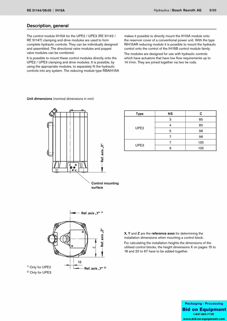
Unit dimensions (nominal dimensions in mm)
1) Only for UPE22) Only for UPE3
X, Y and Z are the reference axes for determining the installation dimensions when mounting a control block.
For calculating the installation heights the dimensions of the utilised control blocks, the height dimensions X on pages 15 to 18 and 20 to 67 have to be added together.
Control mounting surface
Ref. axis „Y“ 1)
Ref
. axi
s „X
“R
ef. a
xis
„Z“
Type NS C
UPE2
3 85
4 85
5 98
7 98
UPE37 135
9 135
Ref. axis „Y“ 2)
Description, general
The control module IH15A for the UPE2 / UPE3 (RE 51142 / RE 51147) clamping and drive modules are used to form complete hydraulic controls. They can be individually designed and assembled. The directional valve modules and poppet valve modules can be combined.
It is possible to mount these control modules directly onto the UPE2 / UPE3 clamping and drive modules. It is possible, by using the appropriate modules, to separately fit the hydraulic controls into any system. The reducing module type RBAIH15A
makes it possible to directly mount the IH15A module onto the reservoir cover of a conventional power unit. With the type RIH15AR reducing module it is possible to mount the hydraulic control onto the control of the IH15B control module family.
The modules are designed for use with hydraulic controls which have actuators that have low flow requirements up to 14 l/min. They are joined together via two tie rods.
4/88 Bosch Rexroth AG Hydraulics IH15A RE 51144/09.05
Technical data (for applicatons outside these parameters, please consult us!)
HydraulicInstallation Optional 1)
Pressure fluid Mineral oil (HL, HLP) to DIN 51524 part 2other pressure fluids on request
Pressure fluid temperature range °C –20 to +80 (with FKM seals)(the permissible viscosity range of the pump and valves have to be taken into account!)
Ambient temperature range °C –30 to +50
Viscosity range mm2/s 2.8 to 500 1)
Maximum permissible degree of pressure fluid contamination. Cleanliness class to ISO 4406 (c)
Class 20/18/15 1)
Valve pressure stage See the associated RE sheet
Directional poppet valve maximum flow Type: KSER1... qv l/min
20 (2/2-directional poppet valve)
12 (3/2-directional poppet valve)
ElectricalVoltage type DC
Available voltages 2) U V 24
Voltage tolerance (nominal voltage) % ±10
Power consumption P W 19 or 30 1)
Switching time toISO 6403
ON T ms 25 to ≤ 80
OFF T ms 10 to 25
Switching frequency switch/h Up to 15.000
Protection to DIN 40050 3) IP 65
Coil temperature 4) °C 1501) Valve details to be taken into account2) Special voltages on request3) With mounted and fixed plug-in connector4) Due to the surface temperatures of the solenoids,
the European standards EN563 and EN982 have to be taken into account!
Hydraulics Bosch Rexroth AGRE 51144/09.05 IH15A 5/88
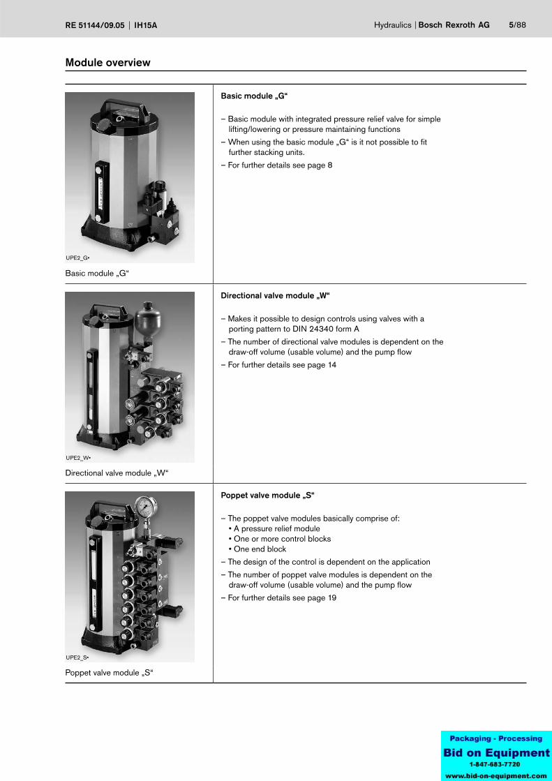
Basic module „G“
– Basic module with integrated pressure relief valve for simple lifting/lowering or pressure maintaining functions
– When using the basic module „G“ is it not possible to fit further stacking units.
– For further details see page 8
Basic module „G“
Directional valve module „W“
– Makes it possible to design controls using valves with aporting pattern to DIN 24340 form A
– The number of directional valve modules is dependent on thedraw-off volume (usable volume) and the pump flow
– For further details see page 14
Directional valve module „W“
Poppet valve module „S“
– The poppet valve modules basically comprise of: • A pressure relief module• One or more control blocks• One end block
– The design of the control is dependent on the application
– The number of poppet valve modules is dependent on thedraw-off volume (usable volume) and the pump flow
– For further details see page 19
Poppet valve module „S“
Module overview
UPE2_G•
UPE2_W•
UPE2_S•
6/88 Bosch Rexroth AG Hydraulics IH15A RE 51144/09.05
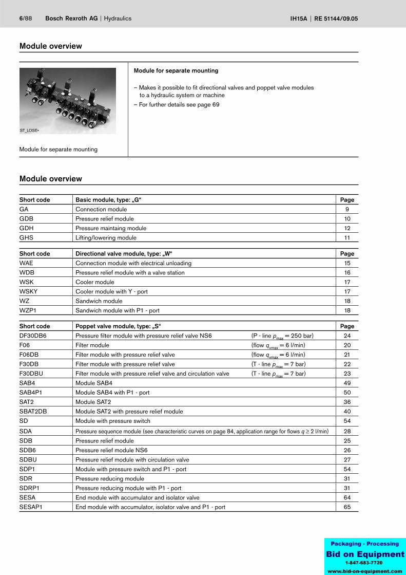
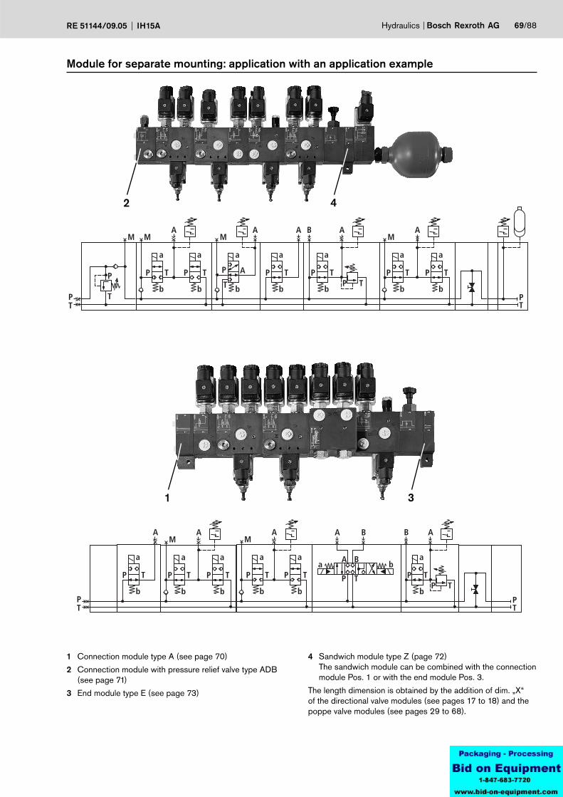
Module for separate mounting
– Makes it possible to fit directional valves and poppet valve modules to a hydraulic system or machine
– For further details see page 69
Module for separate mounting
Module overview
ST_LOSE•
Module overview
Short code Basic module, type: „G“ Page
GA Connection module 9
GDB Pressure relief module 10
GDH Pressure maintaing module 12
GHS Lifting/lowering module 11
Short code Directional valve module, type: „W“ Page
WAE Connection module with electrical unloading 15
WDB Pressure relief module with a valve station 16
WSK Cooler module 17
WSKY Cooler module with Y - port 17
WZ Sandwich module 18
WZP1 Sandwich module with P1 - port 18
Short code Poppet valve module, type: „S“ Page
DF30DB6 Pressure filter module with pressure relief valve NS6 (P - line pmax = 250 bar) 24
F06 Filter module (flow qvmax = 6 l/min) 20
F06DB Filter module with pressure relief valve (flow qvmax = 6 l/min) 21
F30DB Filter module with pressure relief valve (T - line pmax = 7 bar) 22
F30DBU Filter module with pressure relief valve and circulation valve (T - line pmax = 7 bar) 23
SAB4 Module SAB4 49
SAB4P1 Module SAB4 with P1 - port 50
SAT2 Module SAT2 36
SBAT2DB Module SAT2 with pressure relief module 40
SD Module with pressure switch 54
SDA Pressure sequence module (see characteristic curves on page 84, application range for flows q ≥ 2 l/min) 28
SDB Pressure relief module 25
SDB6 Pressure relief module NS6 26
SDBU Pressure relief module with circulation valve 27
SDP1 Module with pressure switch and P1 - port 54
SDR Pressure reducing module 31
SDRP1 Pressure reducing module with P1 - port 31
SESA End module with accumulator and isolator valve 64
SESAP1 End module with accumulator, isolator valve and P1 - port 65

Hydraulics Bosch Rexroth AGRE 51144/09.05 IH15A 7/88
Module overview
Short code Module for separate mounting Page
A Connection module 70
ADB Connection module with pressure relief valve 71
E End module 73
EP1 End module with P1 - port 73
Z Sandwich module 72
ZP1 Sandwich module with P1 - port 72
Short code Reducing module, type: „R“ Page
RBAIH15A Reservoir connection module with reducer to suit IH15A 74
RIH15AR Reducer module IH15B on IH15A (right) 74
Short code Poppet valve module, type: „S“ Page
SP Module SP 34
SPA2 Module SPA2 35
SPA3 Module SPA3 44
SPA3P1 Module SPA3 with P1 - port 45
SPAT2 Module SPAT2 37
SPAT2DB Module SPAT2 with pressure relief valve 39
SPAT3DB Module SBPAT3 with pressure relief valve 47
SPBAT2DB Module SPBAT2 with pressure relief valve 42
SPDB Module with proportional pressure relief valve 29
SPDR Module with proportional pressure reducing valve 30
SPP1 Module P with P1 - port 34
SR Module with check valve 52
SSB Accumulator saftey module 67
SSBP1 Accumulator saftey module with P1 - port 67
SU Circulation module 33
SUA Circulation module with isolator valve 32
SUAP1 Circulation module with isolator valve and P1 - port 32
SUP1 Circulation module with P1 - port 33
SZP1 Sandwich module with P1 - port blocked 56
WSE Directional poppet valve module 57
WSED End module with pressure switch 58
WSEDA End module with pressure switch and isolator valve 61
WSEDAP1 End module with pressure switch, isolator valve and P1 - port 62
WSEDP1 End module with pressure switch and P1 - port 59
WSEP1 End module with P1 - port 57
Short code Module with threads for line mounting Page
SDRG Pressure reducing module with threaded connections 75
SPA2G Module SPA2 with thread connection 76
SPA3G Module SPA3 with thread connection 77

8/88 Bosch Rexroth AG Hydraulics IH15A RE 51144/09.05
Basic module, type „G“: Modules

P
T
P
T
G1/4
G1/4
Y
X22,5
18,5
44,5
1 29
39
T
Hydraulics Bosch Rexroth AGRE 51144/09.05 IH15A 9/88
Basic module, type „G“ (nominal dimensions in mm)
Symbol
Connection module, type „GA“
Dim. Z = 30 mmUnit dimensions
26Seal Seal material FKM = V
Material No. Component description Type code
Connection module 26
IH15MA-1X/GA-
R900992205 IH15MA-1X/GA-V
P
T
M
P
TPT
G1/4
G1/4
G1/4
43,5
4,5
58,5
109
54,5
X
Y
T P
22,5
M
10/88 Bosch Rexroth AG Hydraulics IH15A RE 51144/09.05
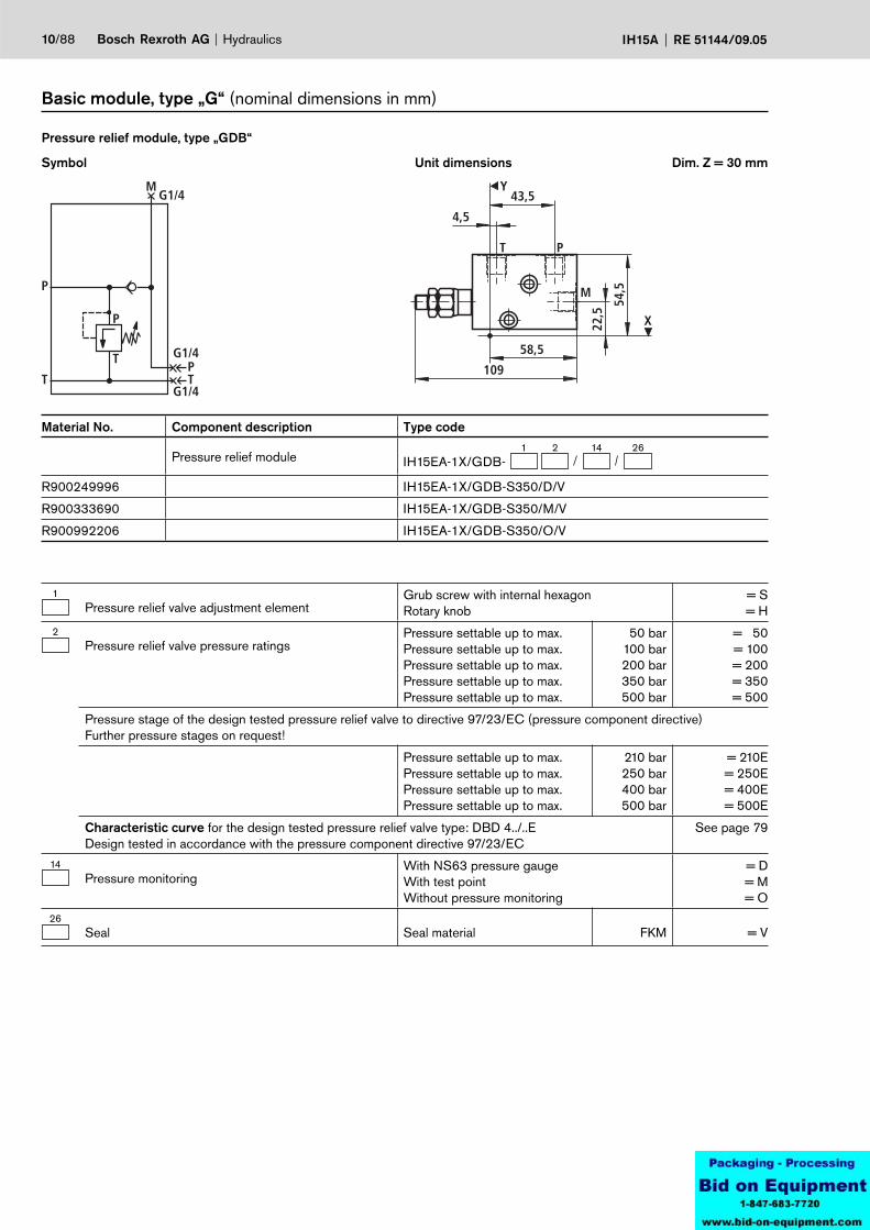
Basic module, type „G“ (nominal dimensions in mm)
Symbol
Pressure relief module, type „GDB“
Dim. Z = 30 mmUnit dimensions
1Pressure relief valve adjustment element
Grub screw with internal hexagon Rotary knob
= S= H
2Pressure relief valve pressure ratings
Pressure settable up to max.Pressure settable up to max.Pressure settable up to max.Pressure settable up to max.Pressure settable up to max.
50 bar100 bar200 bar350 bar500 bar
= 50= 100= 200= 350= 500
Pressure stage of the design tested pressure relief valve to directive 97/23/EC (pressure component directive)Further pressure stages on request!
Pressure settable up to max.Pressure settable up to max.Pressure settable up to max.Pressure settable up to max.
210 bar250 bar400 bar500 bar
= 210E= 250E= 400E= 500E
Characteristic curve for the design tested pressure relief valve type: DBD 4../..EDesign tested in accordance with the pressure component directive 97/23/EC
See page 79
14Pressure monitoring
With NS63 pressure gaugeWith test pointWithout pressure monitoring
= D= M= O
26Seal Seal material FKM = V
Material No. Component description Type code
Pressure relief module1 2 14 26
IH15EA-1X/GDB-
R900249996 IH15EA-1X/GDB-S350/D/V
R900333690 IH15EA-1X/GDB-S350/M/V
R900992206 IH15EA-1X/GDB-S350/O/V

P
T
P
T
a
b
AM
P T
G1/4G1/4
4,5
41,5
58,5109
M
A
Y
X22,5
166,
5
55,5
Hydraulics Bosch Rexroth AGRE 51144/09.05 IH15A 11/88
Symbol
Lifting/lowering module, type „GHS“
Dim. Z = 45 mmUnit dimensions
1Pressure relief valve adjustment element
Grub screw with internal hexagon Rotary knob
= S= H
2Pressure relief valve pressure stage
Pressure settable up to max.Pressure settable up to max.Pressure settable up to max.Pressure settable up to max.Pressure settable up to max.
50 bar100 bar200 bar350 bar500 bar
= 50= 100= 200= 350= 500
Pressure stage of the design tested pressure relief valve to directive 97/23/EC (pressure component directive)Further pressure stages on request!
Pressure settable up to max.Pressure settable up to max.Pressure settable up to max.Pressure settable up to max.
210 bar250 bar400 bar500 bar
= 210E= 250E= 400E= 500E
Characteristic curve for the design tested pressure relief valve type: DBD 4../..EDesign tested in accordance with the pressure component directive 97/23/EC
See page 79
42/2 poppet valve designation
Normally closedNormally open
= N= P
8Poppet valve solenoid voltage Volt 24 V DC = G24
14Pressure monitoring
With pressure gauge NG63With test pointWith pressure monitoring
= D= M= O
26Seal Seal material FKM = V
Basic module, type „G“ (nominal dimensions in mm)
Material No. Component description Type code
Lifting/lowering module1 2 14 26
IH15EA-1X/GHS-4 8
R900712062 IH15EA-1X/GHS-S350/DPG/VR904100577 IH15EA-1X/GHS-S350/MPG/VR901099456 IH15EA-1X/GHS-S350/OPG/V
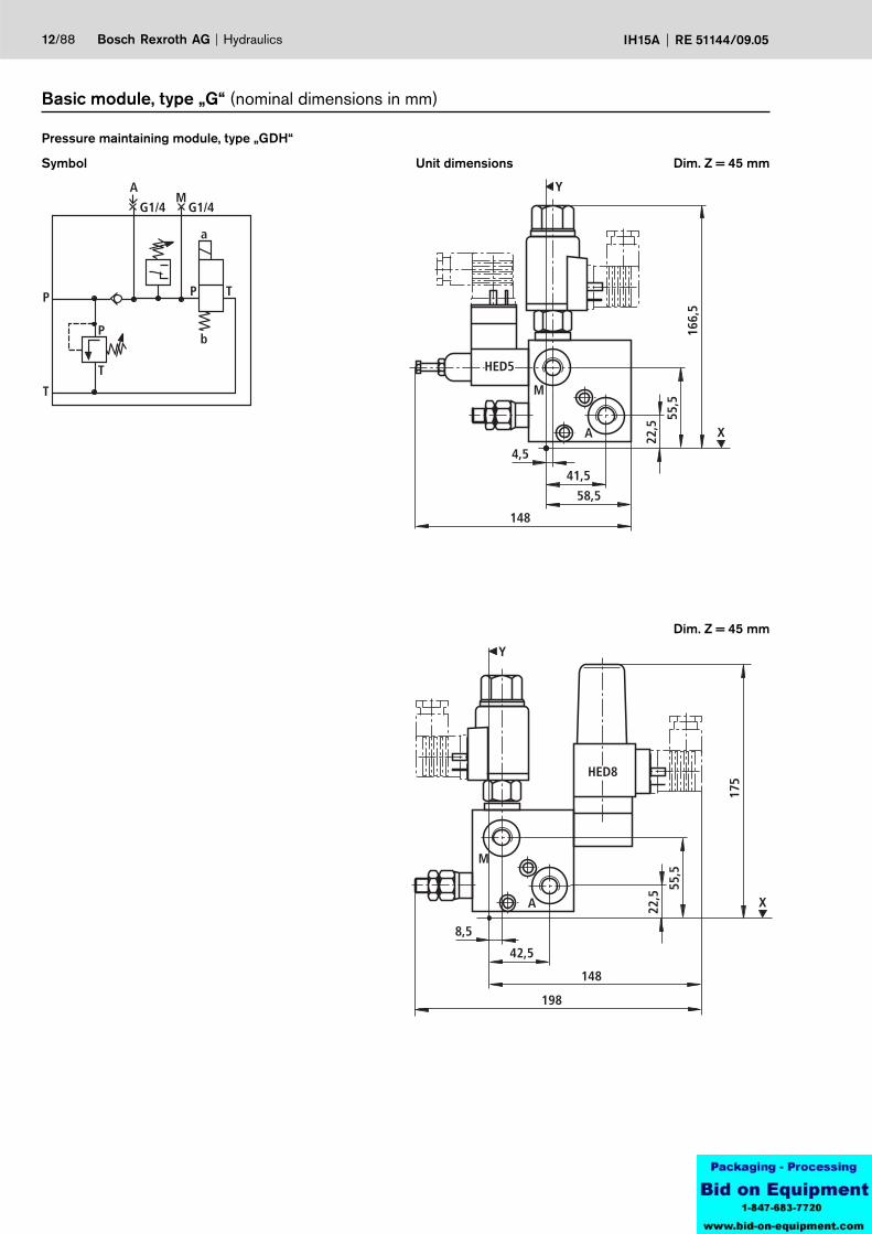
12/88 Bosch Rexroth AG Hydraulics IH15A RE 51144/09.05
Symbol
Pressure maintaining module, type „GDH“
Dim. Z = 45 mmUnit dimensions
Basic module, type „G“ (nominal dimensions in mm)
P
T
P
T
a
b
AM
P T
G1/4 G1/4
4,5
41,5
M
A
Y
X22,5
55,5
148
166,
5
58,5
HED5
8,5
42,5
M
A
Y
X22,5
175
55,5
198
148
HED8
Dim. Z = 45 mm

Hydraulics Bosch Rexroth AGRE 51144/09.05 IH15A 13/88
1Pressure relief valve adjustment element
Grub screw with internal hexagon Rotary knob
= S= H
2Pressure relief valve pressure ratings
Pressure settable up to max.Pressure settable up to max.Pressure settable up to max.Pressure settable up to max.Pressure settable up to max.
50 bar100 bar200 bar350 bar500 bar
= 50= 100= 200= 350= 500
Pressure stage of the design tested pressure relief valve to directive 97/23/EC (pressure component directive)Further pressure stages on request!
Pressure settable up to max.Pressure settable up to max.Pressure settable up to max.Pressure settable up to max.
210 bar250 bar400 bar500 bar
= 210E= 250E= 400E= 500E
Characteristic curve for the design tested pressure relief valve type: DBD 4../..EDesign tested in accordance with the pressure component directive 97/23/EC
See page 79
42/2 poppet valve designation
Normally closedNormally open
= N= P
8Poppet valve solenoid voltage Volt 24 V DC = G24
11Pressure switch
Without pressure switchHED 5 OP1X/…K14HED 8 OP1X/…K14
= No code= HED 5= HED 8
14Pressure monitoring
With NS63 pressure gaugeWith test pointWithout pressure monitoring
= D= M= O
26Seal Seal material FKM = V
Basic module, type „G“ (nominal dimensions in mm)
Material No. Component description Type code
Pressure maintaining module 1 2 14 26
IH15EA-1X/GDH-4 11 8
R900714698 IH15EA-1X/GDH-S350/DPHED8G24/V
R901099353 IH15EA-1X/GDH-S350/MPHED8G24/V
R900266488 IH15EA-1X/GDH-S350/OPHED8G24/V
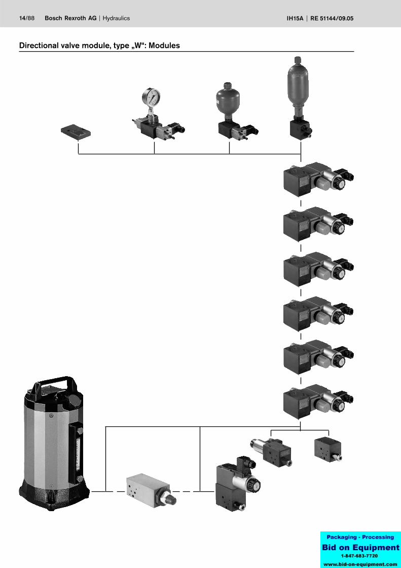
14/88 Bosch Rexroth AG Hydraulics IH15A RE 51144/09.05
Directional valve module, type „W“: Modules
PT
b aP
T
Y
X
150
201,5
49,5
Hydraulics Bosch Rexroth AGRE 51144/09.05 IH15A 15/88
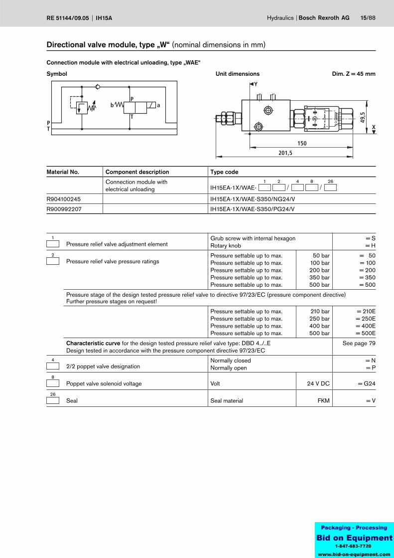
Symbol
Connection module with electrical unloading, type „WAE“
Unit dimensions
Directional valve module, type „W“ (nominal dimensions in mm)
Dim. Z = 45 mm
1Pressure relief valve adjustment element
Grub screw with internal hexagon Rotary knob
= S= H
2Pressure relief valve pressure ratings
Pressure settable up to max.Pressure settable up to max.Pressure settable up to max.Pressure settable up to max.Pressure settable up to max.
50 bar100 bar200 bar350 bar500 bar
= 50= 100= 200= 350= 500
Pressure stage of the design tested pressure relief valve to directive 97/23/EC (pressure component directive)Further pressure stages on request!
Pressure settable up to max.Pressure settable up to max.Pressure settable up to max.Pressure settable up to max.
210 bar250 bar400 bar500 bar
= 210E= 250E= 400E= 500E
Characteristic curve for the design tested pressure relief valve type: DBD 4../..EDesign tested in accordance with the pressure component directive 97/23/EC
See page 79
42/2 poppet valve designation
Normally closedNormally open
= N= P
8Poppet valve solenoid voltage Volt 24 V DC = G24
26Seal Seal material FKM = V
Material No. Component description Type code
Connection module with electrical unloading
1 2 4 26IH15EA-1X/WAE-
8
R904100245 IH15EA-1X/WAE-S350/NG24/V
R900992207 IH15EA-1X/WAE-S350/PG24/V
M
P T
A
a b
A B
A B
P T
P TA B
B
P
T
G1/4
G1/4
G1/4
P T
19,5
51,5 64
,5
58,5
109
X
Y
M
B
A
45,5
36,5
16/88 Bosch Rexroth AG Hydraulics IH15A RE 51144/09.05
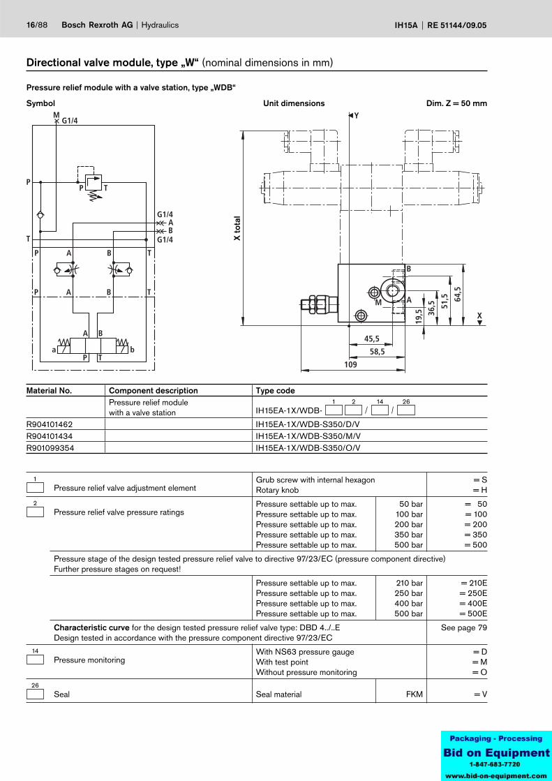
Symbol
Pressure relief module with a valve station, type „WDB“
Unit dimensions
Directional valve module, type „W“ (nominal dimensions in mm)
Dim. Z = 50 mm
Material No. Component description Type codePressure relief modulewith a valve station
1 2 14 26IH15EA-1X/WDB-
R904101462 IH15EA-1X/WDB-S350/D/VR904101434 IH15EA-1X/WDB-S350/M/VR901099354 IH15EA-1X/WDB-S350/O/V
X to
tal
1Pressure relief valve adjustment element
Grub screw with internal hexagon Rotary knob
= S= H
2Pressure relief valve pressure ratings
Pressure settable up to max.Pressure settable up to max.Pressure settable up to max.Pressure settable up to max.Pressure settable up to max.
50 bar100 bar200 bar350 bar500 bar
= 50= 100= 200= 350= 500
Pressure stage of the design tested pressure relief valve to directive 97/23/EC (pressure component directive)Further pressure stages on request!
Pressure settable up to max.Pressure settable up to max.Pressure settable up to max.Pressure settable up to max.
210 bar250 bar400 bar500 bar
= 210E= 250E= 400E= 500E
Characteristic curve for the design tested pressure relief valve type: DBD 4../..EDesign tested in accordance with the pressure component directive 97/23/EC
See page 79
14Pressure monitoring
With NS63 pressure gaugeWith test pointWithout pressure monitoring
= D= M= O
26Seal Seal material FKM = V
PT
T TK
70
49,5
TK
36,5
Y
17,5
58,5
T
X
70
49,5
TK
36,5
Y
17,5
58,5
T
X
PT
T TK
Y
Hydraulics Bosch Rexroth AGRE 51144/09.05 IH15A 17/88
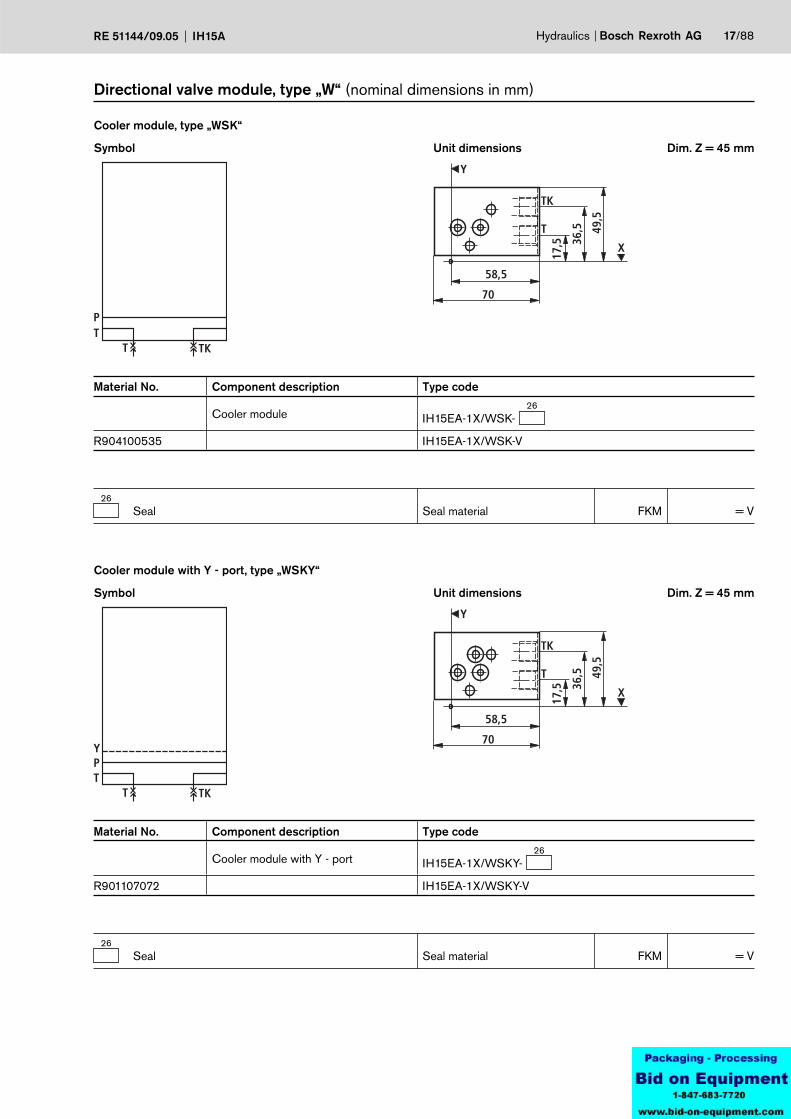
Symbol
Cooler module, type „WSK“
Unit dimensions
Directional valve module, type „W“ (nominal dimensions in mm)
Dim. Z = 45 mm
Material No. Component description Type code
Cooler module26
IH15EA-1X/WSK-
R904100535 IH15EA-1X/WSK-V
26Seal Seal material FKM = V
Symbol
Cooler module with Y - port, type „WSKY“
Unit dimensions Dim. Z = 45 mm
Material No. Component description Type code
Cooler module with Y - port26
IH15EA-1X/WSKY-
R901107072 IH15EA-1X/WSKY-V
26Seal Seal material FKM = V

70
55
A
B
42
Y
13
58,5
A B
PT
P T
G1/4 G1/4
A B
70
55
A
B42
Y
13
58,5
A B
PT
P T
G1/4 G1/4
P1
A B
18/88 Bosch Rexroth AG Hydraulics IH15A RE 51144/09.05
Symbol
Sandwich module, type „WZ“
Unit dimensions
Directional valve module, type „W“ (nominal dimensions in mm)
Dim. Z = 45 mm
Symbol
Sandwich module with P1-port, type „WZP1“
Unit dimensions Dim. Z = 45 mm
Material No. Component description Type code
Sandwich module26
IH15EA-1X/WZ-
R900991532 IH15EA-1X/WZ-V
26Seal Seal material FKM = V
Material No. Component description Type code
Sandwich module with P1 - port26
IH15EA-1X/WZP1-
R904100110 IH15EA-1X/WZP1-V
Hydraulics Bosch Rexroth AGRE 51144/09.05 IH15A 19/88
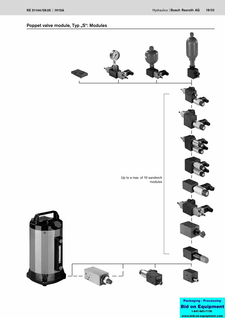
Poppet valve module, Typ „S“: Modules
Up to a max. of 10 sandwich modules
PT
Y
40
119
50
20/88 Bosch Rexroth AG Hydraulics IH15A RE 51144/09.05
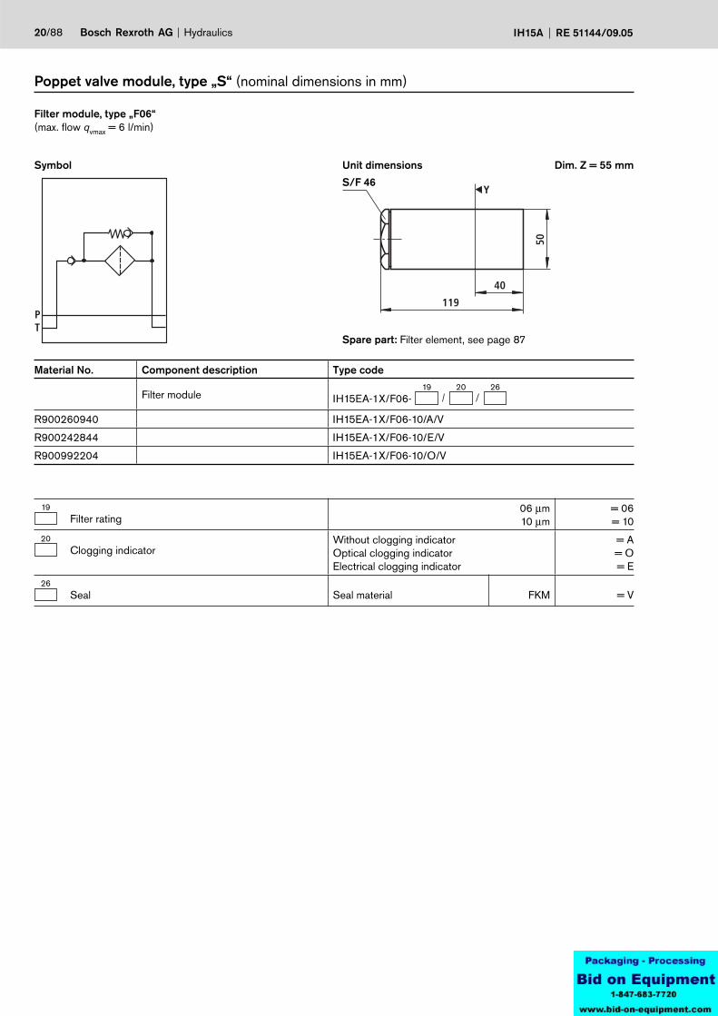
Poppet valve module, type „S“ (nominal dimensions in mm)
Spare part: Filter element, see page 87
Symbol
Filter module, type „F06“ (max. flow qvmax = 6 l/min)
Unit dimensions Dim. Z = 55 mm
S/F 46
Material No. Component description Type code
Filter module19 20 26
IH15EA-1X/F06-
R900260940 IH15EA-1X/F06-10/A/V
R900242844 IH15EA-1X/F06-10/E/V
R900992204 IH15EA-1X/F06-10/O/V
19Filter rating
06 µm10 µm
= 06= 10
20Clogging indicator
Without clogging indicatorOptical clogging indicatorElectrical clogging indicator
= A= O= E
26Seal Seal material FKM = V
58,5
X
Y
T
P
104,
5
74,5
22,5
150
118,9PT
P TG1/4 G1/4
Hydraulics Bosch Rexroth AGRE 51144/09.05 IH15A 21/88
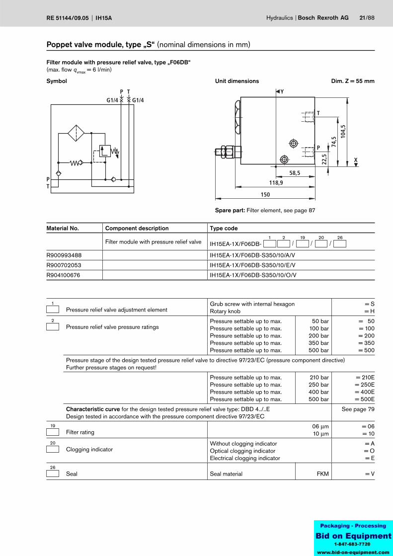
Poppet valve module, type „S“ (nominal dimensions in mm)
Filter module with pressure relief valve, type „F06DB“ (max. flow qvmax = 6 l/min)
Symbol Unit dimensions Dim. Z = 55 mm
Spare part: Filter element, see page 87
Material No. Component description Type code
Filter module with pressure relief valve1 2 19 26
IH15EA-1X/F06DB-20
R900993488 IH15EA-1X/F06DB-S350/10/A/V
R900702053 IH15EA-1X/F06DB-S350/10/E/V
R904100676 IH15EA-1X/F06DB-S350/10/O/V
1Pressure relief valve adjustment element
Grub screw with internal hexagon Rotary knob
= S= H
2Pressure relief valve pressure ratings
Pressure settable up to max.Pressure settable up to max.Pressure settable up to max.Pressure settable up to max.Pressure settable up to max.
50 bar100 bar200 bar350 bar500 bar
= 50= 100= 200= 350= 500
Pressure stage of the design tested pressure relief valve to directive 97/23/EC (pressure component directive)Further pressure stages on request!
Pressure settable up to max.Pressure settable up to max.Pressure settable up to max.Pressure settable up to max.
210 bar250 bar400 bar500 bar
= 210E= 250E= 400E= 500E
Characteristic curve for the design tested pressure relief valve type: DBD 4../..EDesign tested in accordance with the pressure component directive 97/23/EC
See page 79
19Filter rating
06 µm10 µm
= 06= 10
20Clogging indicator
Without clogging indicatorOptical clogging indicatorElectrical clogging indicator
= A= O= E
26Seal Seal material FKM = V

PT
P TG3/8 G3/8
58,5
X
Y
T
P
22,5
88,5 11
4,5
110
150
22/88 Bosch Rexroth AG Hydraulics IH15A RE 51144/09.05
Poppet valve module, type „S“ (nominal dimensions in mm)
Dim. Z = 140 mm
Filter module with pressure relief valve, type „F30DB“ (max. flow qvmax = 30 l/min, pvmax = 7 bar)
Symbol Unit dimensions
Spare part: Filter element, see page 87Assembly tool: Strap wrench, Material No. R904001048
1Pressure relief valve adjustment element
Grub screw with hexagon Rotary knob
= S= H
2Pressure relief valve pressure ratings
Pressure settable up to max.Pressure settable up to max.Pressure settable up to max.Pressure settable up to max.Pressure settable up to max.
50 bar100 bar200 bar350 bar500 bar
= 50= 100= 200= 350= 500
Pressure stage of the design tested pressure relief valve to directive 97/23/EC (pressure component directive)Further pressure stages on request!
Pressure settable up to max.Pressure settable up to max.Pressure settable up to max.Pressure settable up to max.
210 bar250 bar400 bar500 bar
= 210E= 250E= 400E= 500E
Characteristic curve for the design tested pressure relief valve type: DBD 4../..EDesign tested in accordance with the pressure component directive 97/23/EC
See page 79
19Filter rating
06 µm10 µm
= 06= 10
20Clogging indicator
Without clogging indicatorOptical clogging indicatorElectrical clogging indicator
= A= O= E
26Seal Seal material FKM = V
Material No. Component description Type code
Filter module with pressure relief valve1 2 19 26
IH15EA-1X/F30DB-20
R901099541 IH15EA-1X/F30DB-S350/10/A/V
R901099029 IH15EA-1X/F30DB-S350/10/E/V
R904100109 IH15EA-1X/F30DB-S350/10/O/V

P
T
202110
Y
X
58,5
22,5
85,5 11
9,5
P TG 3/8G 3/8
TP
Hydraulics Bosch Rexroth AGRE 51144/09.05 IH15A 23/88
Poppet valve module, type „S“ (nominal dimensions in mm)
Dim. Z = 140 mm
Filter module with pressure relief valve and circulation valve, type „F30DBU“ (max. flow qvmax = 30 l/min, pvmax = 7 bar)
Symbol Unit dimensions
Spare part: Filter element, see page 87Assembly tool: strap wrench, Material No. R904001048
Material No. Component description Type codeFilter module with pressure relief valve and circulation valve
1 2 19 26IH15EA-1X/F30DBU-
204 8
R901099530 IH15EA-1X/F30DBU-S200/PG24/10/A/VR904102272 IH15EA-1X/F30DBU-S200/PG24/10/E/VR901095317 IH15EA-1X/F30DBU-S200/PG24/10/O/V
1Pressure relief valve adjustment element
Grub screw with internal hexagon Rotary knob
= S= H
2Pressure relief valve pressure ratings
Pressure settable up to max.Pressure settable up to max.Pressure settable up to max.Pressure settable up to max.Pressure settable up to max.
50 bar100 bar200 bar350 bar500 bar
= 50= 100= 200= 350= 500
Pressure stage of the design tested pressure relief valve to directive 97/23/EC (pressure component directive)Further pressure stages on request!
Pressure settable up to max.Pressure settable up to max.Pressure settable up to max.Pressure settable up to max.
210 bar250 bar400 bar500 bar
= 210E= 250E= 400E= 500E
Characteristic curve for the design tested pressure relief valve type: DBD 4../..EDesign tested in accordance with the pressure component directive 97/23/EC
See page 79
42/2 poppet valve designation
Normally closedNormally open
= N= P
8Poppet valve solenoid voltage Volt 24 V DC = G24
19Filter rating
06 µm10 µm
= 06= 10
20Clogging indicator
Without clogging indicatorOptical clogging indicatorElectrical clogging indicator
= A= O= E
26Seal Seal material FKM = V
PT
TP
G3/8G3/8
Y
X
58,5
100
172
45,5
87,5 11
9,5
P
T
24/88 Bosch Rexroth AG Hydraulics IH15A RE 51144/09.05
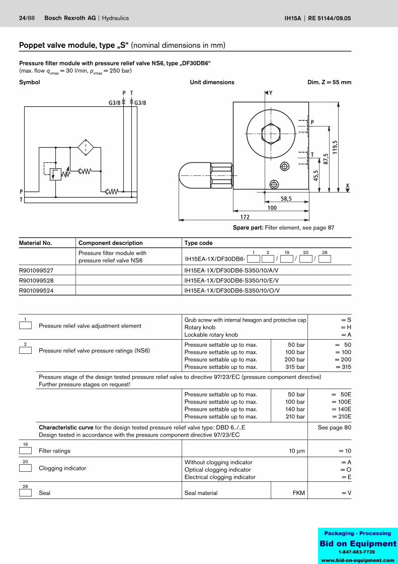
Poppet valve module, type „S“ (nominal dimensions in mm)
Symbol
Pressure filter module with pressure relief valve NS6, type „DF30DB6“ (max. flow qvmax = 30 l/min, pvmax = 250 bar)
Unit dimensions Dim. Z = 55 mm
Material No. Component description Type code
Pressure filter module withpressure relief valve NS6
1 2 19 26IH15EA-1X/DF30DB6-
20
R901099527 IH15EA-1X/DF30DB6-S350/10/A/V
R901099528 IH15EA-1X/DF30DB6-S350/10/E/V
R901099524 IH15EA-1X/DF30DB6-S350/10/O/V
1Pressure relief valve adjustment element
Grub screw with internal hexagon and protective capRotary knobLockable rotary knob
= S= H= A
2Pressure relief valve pressure ratings (NS6)
Pressure settable up to max.Pressure settable up to max.Pressure settable up to max.Pressure settable up to max.
50 bar100 bar200 bar315 bar
= 50= 100= 200= 315
Pressure stage of the design tested pressure relief valve to directive 97/23/EC (pressure component directive)Further pressure stages on request!
Pressure settable up to max.Pressure settable up to max.Pressure settable up to max.Pressure settable up to max.
50 bar100 bar140 bar210 bar
= 50E= 100E= 140E= 210E
Characteristic curve for the design tested pressure relief valve type: DBD 6../..EDesign tested in accordance with the pressure component directive 97/23/EC
See page 80
19Filter ratings 10 µm = 10
20Clogging indicator
Without clogging indicatorOptical clogging indicatorElectrical clogging indicator
= A= O= E
26Seal Seal material FKM = V
Spare part: Filter element, see page 87
58,5
X
Y
T
P 54,5
41,5
17,5
109
PT
P T
P
T
G1/4 G1/4
Hydraulics Bosch Rexroth AGRE 51144/09.05 IH15A 25/88
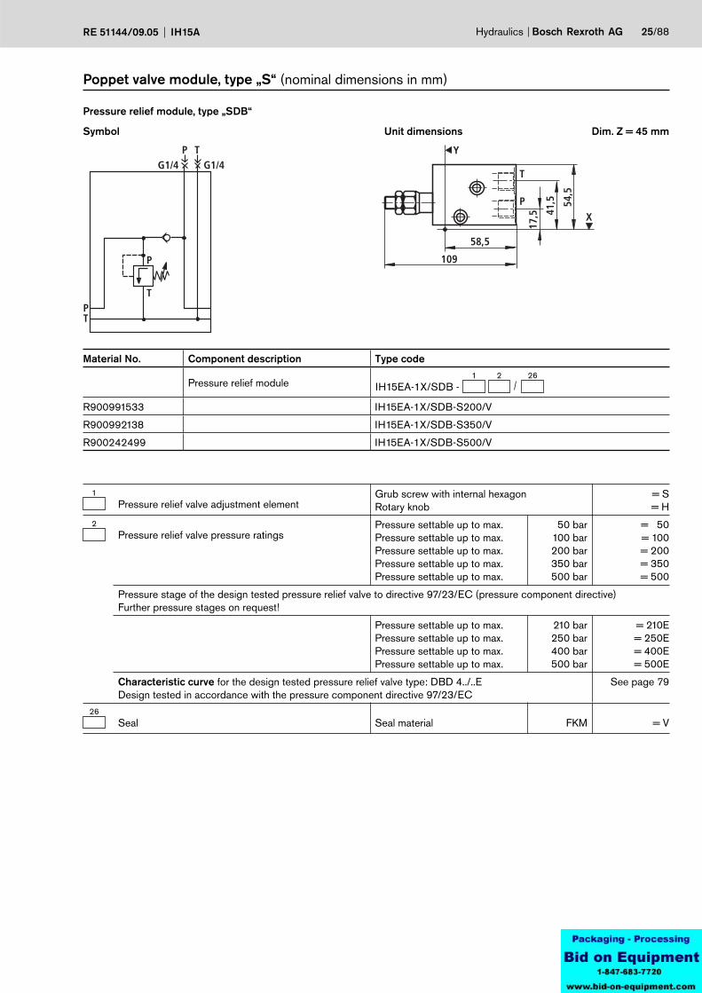
Material No. Component description Type code
Pressure relief module1 2 26
IH15EA-1X/SDB -
R900991533 IH15EA-1X/SDB-S200/V
R900992138 IH15EA-1X/SDB-S350/V
R900242499 IH15EA-1X/SDB-S500/V
1Pressure relief valve adjustment element
Grub screw with internal hexagon Rotary knob
= S= H
2Pressure relief valve pressure ratings
Pressure settable up to max.Pressure settable up to max.Pressure settable up to max.Pressure settable up to max.Pressure settable up to max.
50 bar100 bar200 bar350 bar500 bar
= 50= 100= 200= 350= 500
Pressure stage of the design tested pressure relief valve to directive 97/23/EC (pressure component directive)Further pressure stages on request!
Pressure settable up to max.Pressure settable up to max.Pressure settable up to max.Pressure settable up to max.
210 bar250 bar400 bar500 bar
= 210E= 250E= 400E= 500E
Characteristic curve for the design tested pressure relief valve type: DBD 4../..EDesign tested in accordance with the pressure component directive 97/23/EC
See page 79
26Seal Seal material FKM = V
Symbol
Pressure relief module, type „SDB“
Unit dimensions
Poppet valve module, type „S“ (nominal dimensions in mm)
Dim. Z = 45 mm
PT
G1/4
P
G1/4
TY
X
58,5
100
172
17,5
41,5 54
,5
T
P
26/88 Bosch Rexroth AG Hydraulics IH15A RE 51144/09.05
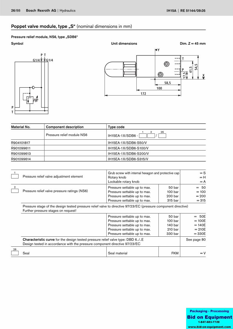
Material No. Component description Type code
Pressure relief module NS61 2 26
IH15EA-1X/SDB6 -
R904101817 IH15EA-1X/SDB6-S50/V
R901099611 IH15EA-1X/SDB6-S100/V
R901099613 IH15EA-1X/SDB6-S200/V
R901099614 IH15EA-1X/SDB6-S315/V
Symbol
Pressure relief module, NS6, type „SDB6“
Unit dimensions
Poppet valve module, type „S“ (nominal dimensions in mm)
Dim. Z = 45 mm
1Pressure relief valve adjustment element
Grub screw with internal hexagon and protective capRotary knobLockable rotary knob
= S= H= A
2Pressure relief valve pressure ratings (NS6)
Pressure settable up to max.Pressure settable up to max.Pressure settable up to max.Pressure settable up to max.
50 bar100 bar200 bar315 bar
= 50= 100= 200= 315
Pressure stage of the design tested pressure relief valve to directive 97/23/EC (pressure component directive)Further pressure stages on request!
Pressure settable up to max.Pressure settable up to max.Pressure settable up to max.Pressure settable up to max.Pressure settable up to max.
50 bar100 bar140 bar210 bar330 bar
= 50E= 100E= 140E= 210E= 330E
Characteristic curve for the design tested pressure relief valve type: DBD 6../..EDesign tested in accordance with the pressure component directive 97/23/EC
See page 80
26Seal Seal material FKM = V
Y
X
162
79,5
57,5
22,570
58,5
T
P
G1/4
PT
P TG1/4
P T
b
a
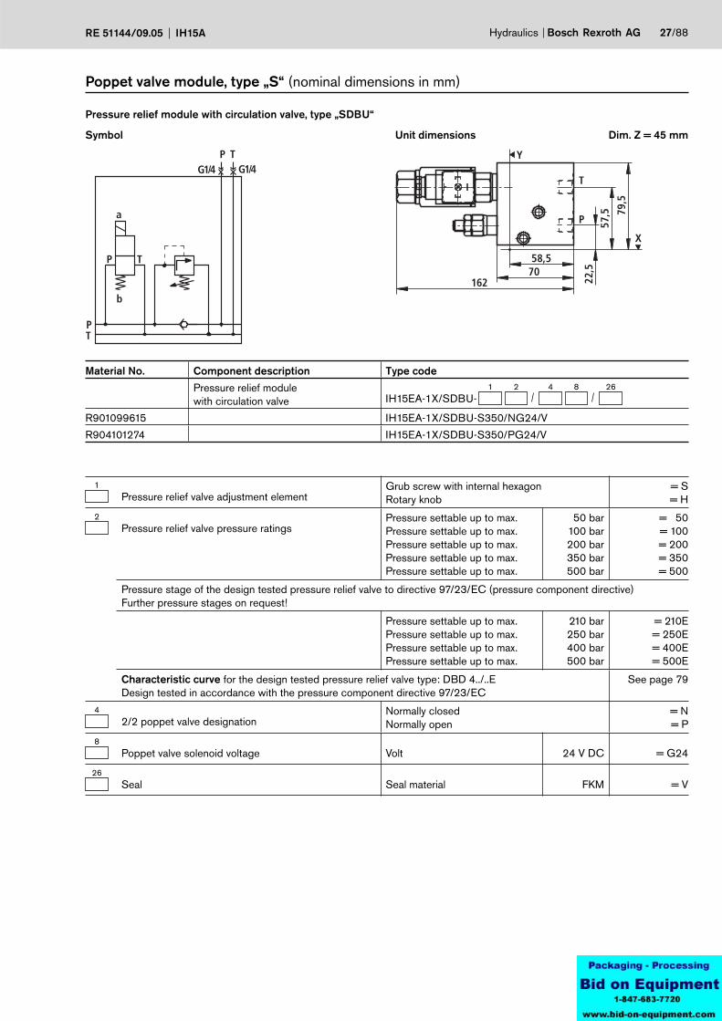
Hydraulics Bosch Rexroth AGRE 51144/09.05 IH15A 27/88
1Pressure relief valve adjustment element
Grub screw with internal hexagon Rotary knob
= S= H
2Pressure relief valve pressure ratings
Pressure settable up to max.Pressure settable up to max.Pressure settable up to max.Pressure settable up to max.Pressure settable up to max.
50 bar100 bar200 bar350 bar500 bar
= 50= 100= 200= 350= 500
Pressure stage of the design tested pressure relief valve to directive 97/23/EC (pressure component directive)Further pressure stages on request!
Pressure settable up to max.Pressure settable up to max.Pressure settable up to max.Pressure settable up to max.
210 bar250 bar400 bar500 bar
= 210E= 250E= 400E= 500E
Characteristic curve for the design tested pressure relief valve type: DBD 4../..EDesign tested in accordance with the pressure component directive 97/23/EC
See page 79
42/2 poppet valve designation
Normally closedNormally open
= N= P
8Poppet valve solenoid voltage Volt 24 V DC = G24
26Seal Seal material FKM = V
Material No. Component description Type code
Pressure relief module with circulation valve
1 2 26IH15EA-1X/SDBU-
4 8
R901099615 IH15EA-1X/SDBU-S350/NG24/V
R904101274 IH15EA-1X/SDBU-S350/PG24/V
Symbol
Pressure relief module with circulation valve, type „SDBU“
Unit dimensions
Poppet valve module, type „S“ (nominal dimensions in mm)
Dim. Z = 45 mm
Y
41,5
X
74,5
83,5
130
M
114,5
PT
P
T
G1/4M
(Y)
28/88 Bosch Rexroth AG Hydraulics IH15A RE 51144/09.05
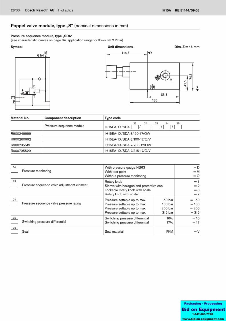
Material No. Component description Type code
Pressure sequence module23 24 26
IH15EA-1X/SDA-25 14
R900249999 IH15EA-1X/SDA-3/ 50-17/O/V
R900260992 IH15EA-1X/SDA-3/100-17/O/V
R900705519 IH15EA-1X/SDA-7/200-17/O/V
R900705520 IH15EA-1X/SDA-7/315-17/O/V
Symbol
Pressure sequence module, type „SDA“(see characteristic curves on page 84, application range for flows q ≥ 2 l/min)
Unit dimensions
Poppet valve module, type „S“ (nominal dimensions in mm)
Dim. Z = 45 mm
14Pressure monitoring
With pressure gauge NS63With test pointWithout pressure monitoring
= D= M= O
23Pressure sequence valve adjustment element
Rotary knobSleeve with hexagon and protective capLockable rotary knob with scaleRotary knob with scale
= 1= 2= 3= 7
24Pressure sequence valve pressure rating
Pressure settable up to max. Pressure settable up to max. Pressure settable up to max. Pressure settable up to max.
50 bar100 bar200 bar315 bar
= 50= 100= 200= 315
25Switching pressure differential
Switching pressure differentialSwitching pressure differential
10%17%
= 10= 17
26Seal Seal material FKM = V
Y
35
58,5
70
132
M
PT
Hydraulics Bosch Rexroth AGRE 51144/09.05 IH15A 29/88
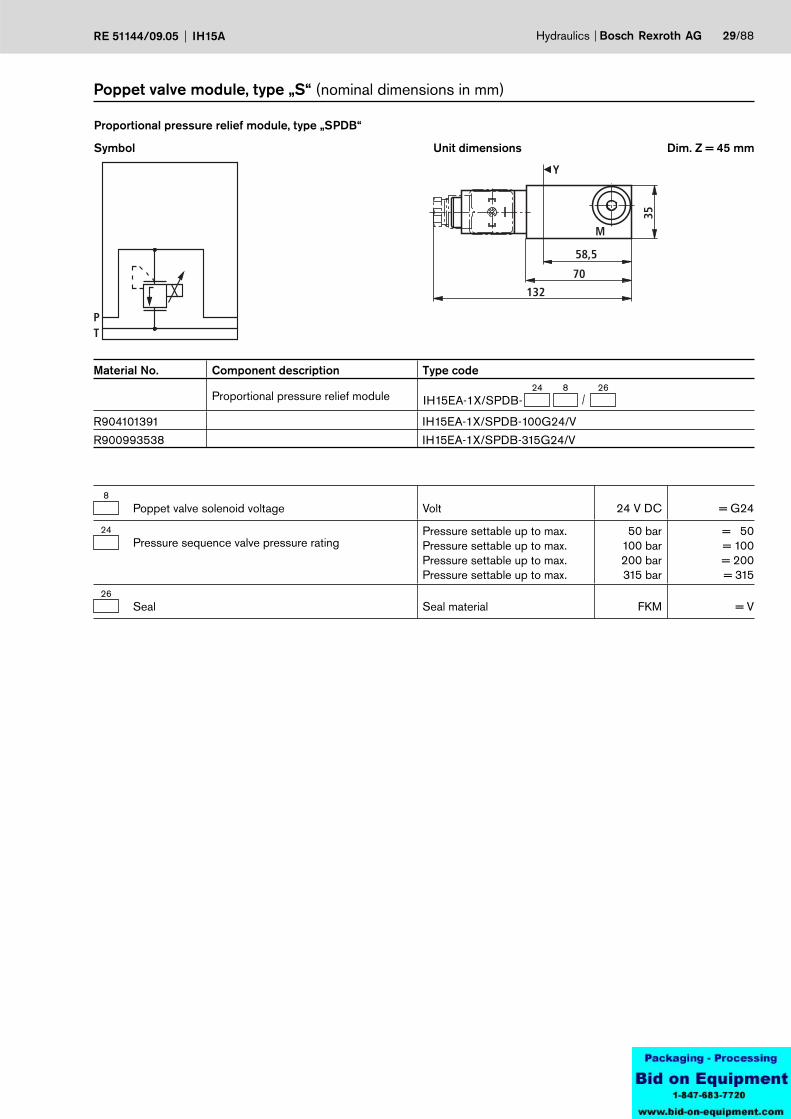
Poppet valve module, type „S“ (nominal dimensions in mm)
Symbol
Proportional pressure relief module, type „SPDB“
Unit dimensions Dim. Z = 45 mm
Material No. Component description Type code
Proportional pressure relief module24 8
IH15EA-1X/SPDB-26
R904101391 IH15EA-1X/SPDB-100G24/V
R900993538 IH15EA-1X/SPDB-315G24/V
8Poppet valve solenoid voltage Volt 24 V DC = G24
24Pressure sequence valve pressure rating
Pressure settable up to max. Pressure settable up to max. Pressure settable up to max. Pressure settable up to max.
50 bar100 bar200 bar315 bar
= 50= 100= 200= 315
26Seal Seal material FKM = V
PT
MG1/4 Y
35
58,5
70
169
M
30/88 Bosch Rexroth AG Hydraulics IH15A RE 51144/09.05
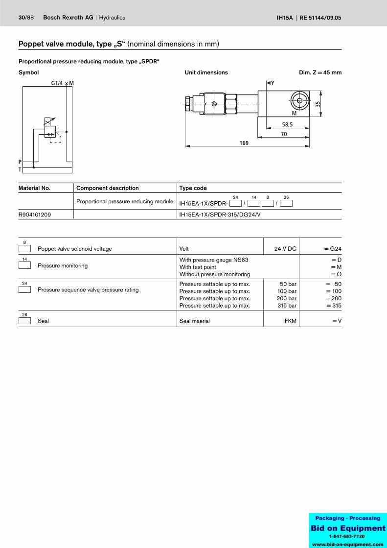
Poppet valve module, type „S“ (nominal dimensions in mm)
Symbol
Proportional pressure reducing module, type „SPDR“
Unit dimensions Dim. Z = 45 mm
Material No. Component description Type code
Proportional pressure reducing module24 14
IH15EA-1X/SPDR-268
R904101209 IH15EA-1X/SPDR-315/DG24/V
8Poppet valve solenoid voltage Volt 24 V DC = G24
14Pressure monitoring
With pressure gauge NS63With test pointWithout pressure monitoring
= D= M= O
24Pressure sequence valve pressure rating
Pressure settable up to max. Pressure settable up to max. Pressure settable up to max. Pressure settable up to max.
50 bar100 bar200 bar315 bar
= 50= 100= 200= 315
26Seal Seal maerial FKM = V
Y
75,5
176,5
22,5 45
M
PT
MG1/4
PT
MG1/4
P1
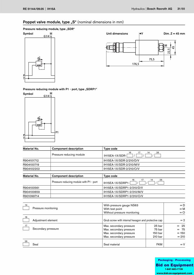
Hydraulics Bosch Rexroth AGRE 51144/09.05 IH15A 31/88
Material No. Component description Type code
Pressure reducing module16 17 26
IH15EA-1X/SDR-14
R904101712 IH15EA-1X/SDR-2/210/D/VR904100719 IH15EA-1X/SDR-2/210/M/VR904102202 IH15EA-1X/SDR-2/210/O/V
14Pressure monitoring
With pressure gauge NS63With test pointWithout pressure monitoring
= D= M= O
16Adjustment element Grub screw with internal hexagon and protective cap = 2
17Secondary prressure
Max. secondary pressureMax. secondary pressureMax. secondary pressureMax. secondary pressure
25 bar75 bar
150 bar210 bar
= 25= 75= 150= 210
26Seal Seal material FKM = V
Poppet valve module, type „S“ (nominal dimensions in mm)
Symbol
Pressure reducing module, type „SDR“
Unit dimensions Dim. Z = 45 mm
Symbol
Pressure reducing module with P1 - port, type „SDRP1“
Material No. Component description Type code
Pressure reducing module with P1 - port16 17 26
IH15EA-1X/SDRP1-14
R904100561 IH15EA-1X/SDRP1-2/210/D/VR904100659 IH15EA-1X/SDRP1-2/210/M/VR901099714 IH15EA-1X/SDRP1-2/210/O/V

58,5
40
Y
112,5
PT
PT
P1
32/88 Bosch Rexroth AG Hydraulics IH15A RE 51144/09.05
26Seal Seal material FKM = V
Material No. Component description Type code
Circulation module with isolator valve26
IH15EA-1X/SUA-
R900992137 IH15EA-1X/SUA-V
Symbol
Circulation module with isolator valve, type „SUA“
Unit dimensions
Poppet valve module, type „S“ (nominal dimensions in mm)
Dim. Z = 45 mm
Symbol
Circulation module with isolator valve and P1 - port, type „SUAP1“
Material No. Component desciption Type code
Circulation module with isolator valve and P1 - port
26IH15EA-1X/SUAP1-
R901099721 IH15EA-1X/SUAP1-V
58,5
162
40
Y
PT
b
a
P T
PT
b
a
P T
P1
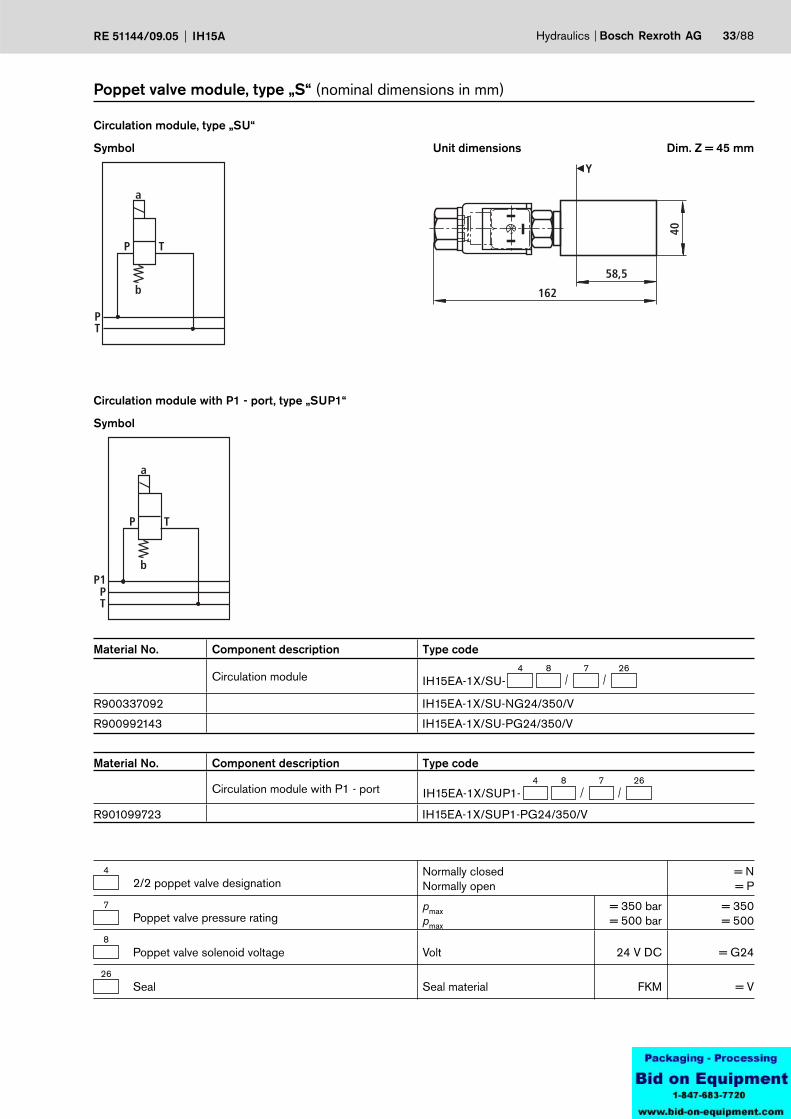
Hydraulics Bosch Rexroth AGRE 51144/09.05 IH15A 33/88
Material No. Component description Type code
Circulation module4 8 26
IH15EA-1X/SU-7
R900337092 IH15EA-1X/SU-NG24/350/V
R900992143 IH15EA-1X/SU-PG24/350/V
Symbol
Circulation module, type „SU“
Unit dimensions
Poppet valve module, type „S“ (nominal dimensions in mm)
Dim. Z = 45 mm
Symbol
Circulation module with P1 - port, type „SUP1“
Material No. Component description Type code
Circulation module with P1 - port4 8 26
IH15EA-1X/SUP1-7
R901099723 IH15EA-1X/SUP1-PG24/350/V
42/2 poppet valve designation
Normally closedNormally open
= N= P
7Poppet valve pressure rating
pmax pmax
= 350 bar= 500 bar
= 350= 500
8Poppet valve solenoid voltage Volt 24 V DC = G24
26Seal Seal material FKM = V
58,5
162
40
Y
PT
b
a
P T
PT
b
a
P T
P1
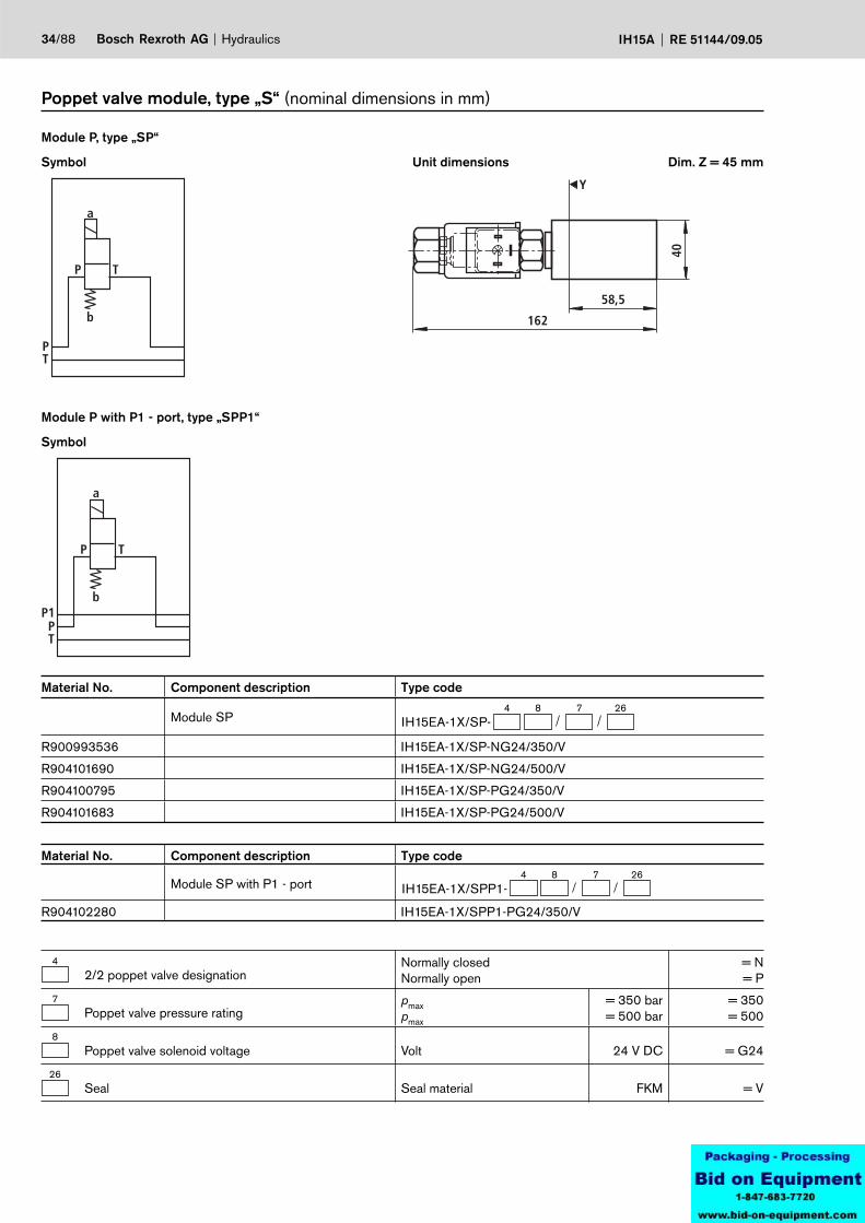
34/88 Bosch Rexroth AG Hydraulics IH15A RE 51144/09.05
Material No. Component description Type code
Module SP 4 8 26
IH15EA-1X/SP-7
R900993536 IH15EA-1X/SP-NG24/350/V
R904101690 IH15EA-1X/SP-NG24/500/V
R904100795 IH15EA-1X/SP-PG24/350/V
R904101683 IH15EA-1X/SP-PG24/500/V
Symbol
Module P, type „SP“
Unit dimensions
Poppet valve module, type „S“ (nominal dimensions in mm)
Dim. Z = 45 mm
Symbol
Module P with P1 - port, type „SPP1“
Material No. Component description Type code
Module SP with P1 - port4 8 26
IH15EA-1X/SPP1-7
R904102280 IH15EA-1X/SPP1-PG24/350/V
42/2 poppet valve designation
Normally closedNormally open
= N= P
7Poppet valve pressure rating
pmax pmax
= 350 bar= 500 bar
= 350= 500
8Poppet valve solenoid voltage Volt 24 V DC = G24
26Seal Seal material FKM = V
162
58,5
38,5
A
40
Y
20
58,5
38,5
A
40
Y
20
136,5
240
HED5
A
PT
a
b
P T
G1/4
A
PT
a
b
P T
G1/4
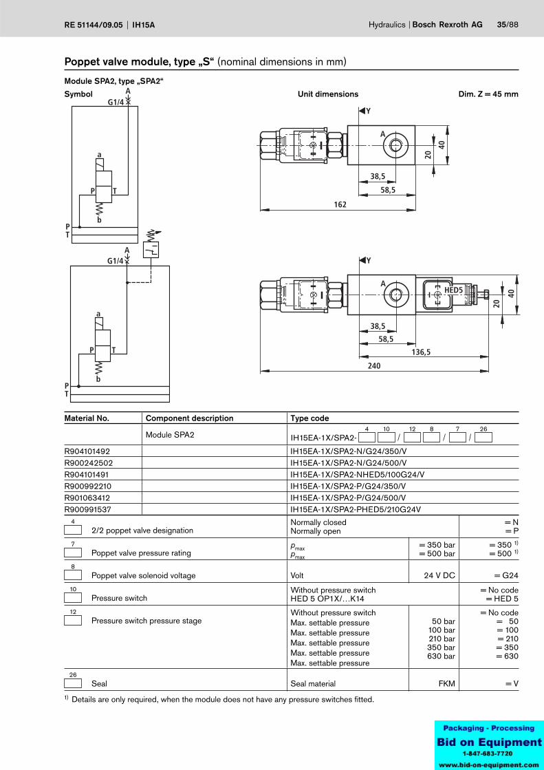
Hydraulics Bosch Rexroth AGRE 51144/09.05 IH15A 35/88
Material No. Component description Type code
Module SPA2 4 10 712 8 26
IH15EA-1X/SPA2-
R904101492 IH15EA-1X/SPA2-N/G24/350/VR900242502 IH15EA-1X/SPA2-N/G24/500/VR904101491 IH15EA-1X/SPA2-NHED5/100G24/VR900992210 IH15EA-1X/SPA2-P/G24/350/VR901063412 IH15EA-1X/SPA2-P/G24/500/VR900991537 IH15EA-1X/SPA2-PHED5/210G24V
Symbol
Module SPA2, type „SPA2“
Unit dimensions
Poppet valve module, type „S“ (nominal dimensions in mm)
Dim. Z = 45 mm
42/2 poppet valve designation
Normally closedNormally open
= N= P
7Poppet valve pressure rating
pmax pmax
= 350 bar= 500 bar
= 350 1)
= 500 1)
8Poppet valve solenoid voltage Volt 24 V DC = G24
10Pressure switch
Without pressure switchHED 5 OP1X/…K14
= No code= HED 5
12Pressure switch pressure stage
Without pressure switchMax. settable pressureMax. settable pressureMax. settable pressureMax. settable pressureMax. settable pressure
50 bar100 bar210 bar350 bar630 bar
= No code= 50= 100= 210= 350= 630
26Seal Seal material FKM = V
1) Details are only required, when the module does not have any pressure switches fitted.

43,5
14
Y
58,5162
A
40
A
PT
a
b
P T
G1/4
36/88 Bosch Rexroth AG Hydraulics IH15A RE 51144/09.05
Material No. Component description Type code
Module SAT24 8 26
IH15EA-1X/SAT2-7
R904100867 IH15EA-1X/SAT2-NG24/350/V
R901063391 IH15EA-1X/SAT2-NG24/500/V
R901065613 IH15EA-1X/SAT2-PG24/350/V
R901063388 IH15EA-1X/SAT2-PG24/500/V
Symbol
Module A – T, type „SAT2“
Unit dimensions
Poppet valve module, type „S“ (nominal dimensions in mm)
Dim. Z = 45 mm
42/2 poppet valve designation
Normally closedNormally open
= N= P
7Poppet valve pressure rating
pmax pmax
= 350 bar= 500 bar
= 350= 500
8Poppet valve solenoid voltage Volt 24 V DC = G24
26Seal Seal material FKM = V
A
M
25,5
43,5
58,5
162
13
80
43
Y
2
1
MA
PT
a
b
a
b
P T P T
G1/4 G1/4
21
A
M
25,5
43,5
13
80
43
Y
240
136,5
2
1
HED5
MA
PT
a
b
a
b
P T P T
21
G1/4 G1/4
A
M
25,5
43,5
13
80
43
Y
272
168,5
2
1
HED8
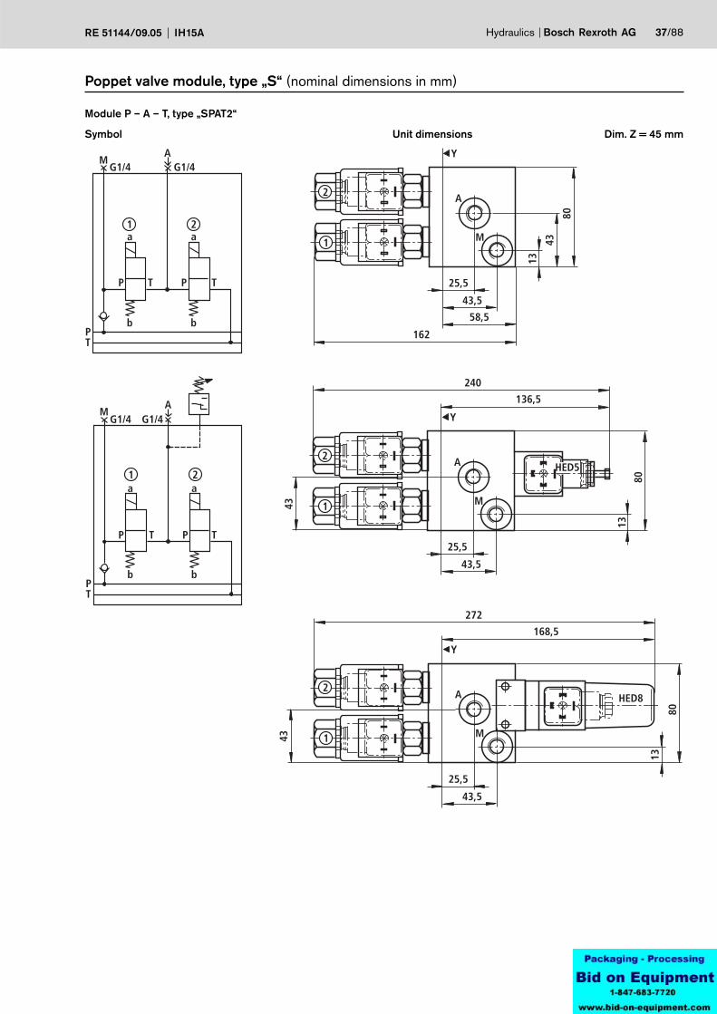
Hydraulics Bosch Rexroth AGRE 51144/09.05 IH15A 37/88
Symbol
Module P – A – T, type „SPAT2“
Unit dimensions
Poppet valve module, type „S“ (nominal dimensions in mm)
Dim. Z = 45 mm
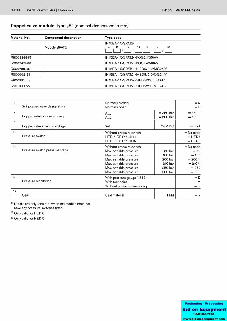
38/88 Bosch Rexroth AG Hydraulics IH15A RE 51144/09.05
Material No. Component description Type code
Module SPAT2 IH15EA-1X/SPAT2-
4 11 12 14 8 7 26
R900334895 IH15EA-1X/SPAT2-N/OG24/350/V
R900242500 IH15EA-1X/SPAT2-N/OG24/500/V
R900708437 IH15EA-1X/SPAT2-NHED5/210/MG24/V
R900992131 IH15EA-1X/SPAT2-NHED5/210/OG24/V
R900991528 IH15EA-1X/SPAT2-PHED5/210/OG24/V
R901100022 IH15EA-1X/SPAT2-PHED5/210/MG24/V
Poppet valve module, type „S“ (nominal dimensions in mm)
42/2 poppet valve designation
Normally closedNormally open
= N= P
7Poppet valve pressure rating
pmax pmax
= 350 bar= 500 bar
= 350 1)
= 500 1)
8Poppet valve solenoid voltage Volt 24 V DC = G24
11Pressure switch
Without pressure switchHED 5 OP1X/…K14HED 8 OP1X/…K15
= No code= HED5= HED8
12Pressure switch pressure stage
Without pressure switchMax. settable pressureMax. settable pressureMax. settable pressureMax. settable pressureMax. settable pressureMax. settable pressure
50 bar100 bar200 bar210 bar350 bar630 bar
= No code= 50
= 100= 200 2)
= 210 3)
= 350= 630
14Pressure monitoring
With pressure gauge NS63With test pointWithout pressure monitoring
= D= M= O
26Seal Seal material FKM = V
1) Details are only required, when the module does not have any pressure switches fitted.
2) Only valid for HED 83) Only valid for HED 5
A
M
25,5
43,5
13
80
43
Y
98
201
2
1
M
PT
b
A
a a
b
P T P T
21
G1/4 G1/4
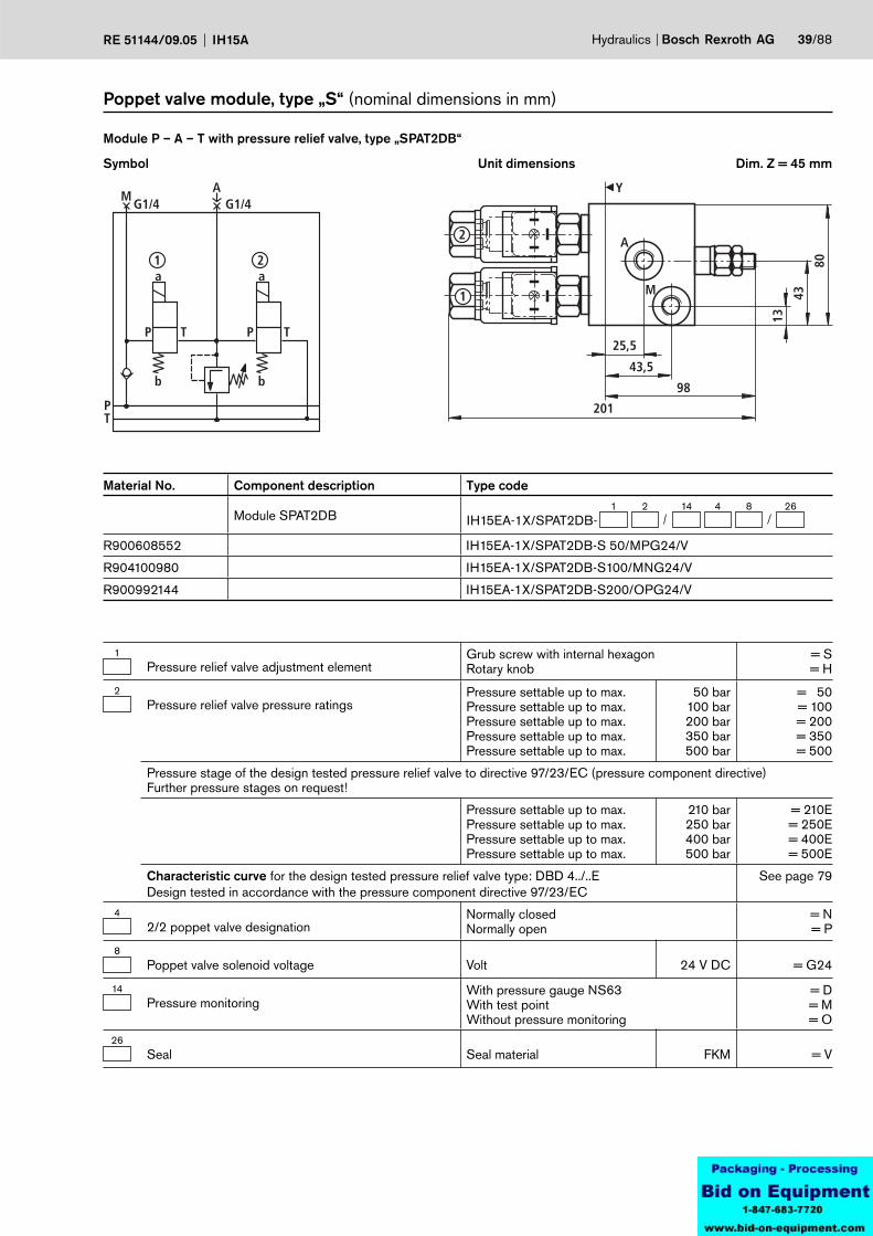
Hydraulics Bosch Rexroth AGRE 51144/09.05 IH15A 39/88
Material No. Component description Type code
Module SPAT2DB1 2 26
IH15EA-1X/SPAT2DB-8414
R900608552 IH15EA-1X/SPAT2DB-S 50/MPG24/V
R904100980 IH15EA-1X/SPAT2DB-S100/MNG24/V
R900992144 IH15EA-1X/SPAT2DB-S200/OPG24/V
Symbol
Module P – A – T with pressure relief valve, type „SPAT2DB“
Unit dimensions
Poppet valve module, type „S“ (nominal dimensions in mm)
Dim. Z = 45 mm
1Pressure relief valve adjustment element
Grub screw with internal hexagon Rotary knob
= S= H
2Pressure relief valve pressure ratings
Pressure settable up to max.Pressure settable up to max.Pressure settable up to max.Pressure settable up to max.Pressure settable up to max.
50 bar100 bar200 bar350 bar500 bar
= 50= 100= 200= 350= 500
Pressure stage of the design tested pressure relief valve to directive 97/23/EC (pressure component directive)Further pressure stages on request!
Pressure settable up to max.Pressure settable up to max.Pressure settable up to max.Pressure settable up to max.
210 bar250 bar400 bar500 bar
= 210E= 250E= 400E= 500E
Characteristic curve for the design tested pressure relief valve type: DBD 4../..EDesign tested in accordance with the pressure component directive 97/23/EC
See page 79
42/2 poppet valve designation
Normally closedNormally open
= N= P
8Poppet valve solenoid voltage Volt 24 V DC = G24
14Pressure monitoring
With pressure gauge NS63With test pointWithout pressure monitoring
= D= M= O
26Seal Seal material FKM = V
25,5
43,5
13
Y
A
58,5
162
B 50
75
A
PT
a
b
B
P T
G1/4 G1/4
25,5
43,5
13
Y
A
B 50
75
136,5
240
HED5
A
PT
a
b
B
P T
G1/4 G1/4
40/88 Bosch Rexroth AG Hydraulics IH15A RE 51144/09.05
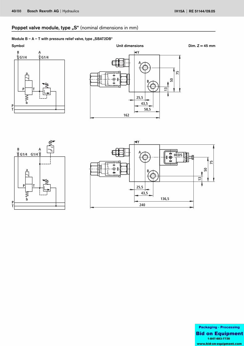
Symbol
Module B – A – T with pressure relief valve, type „SBAT2DB“
Unit dimensions
Poppet valve module, type „S“ (nominal dimensions in mm)
Dim. Z = 45 mm
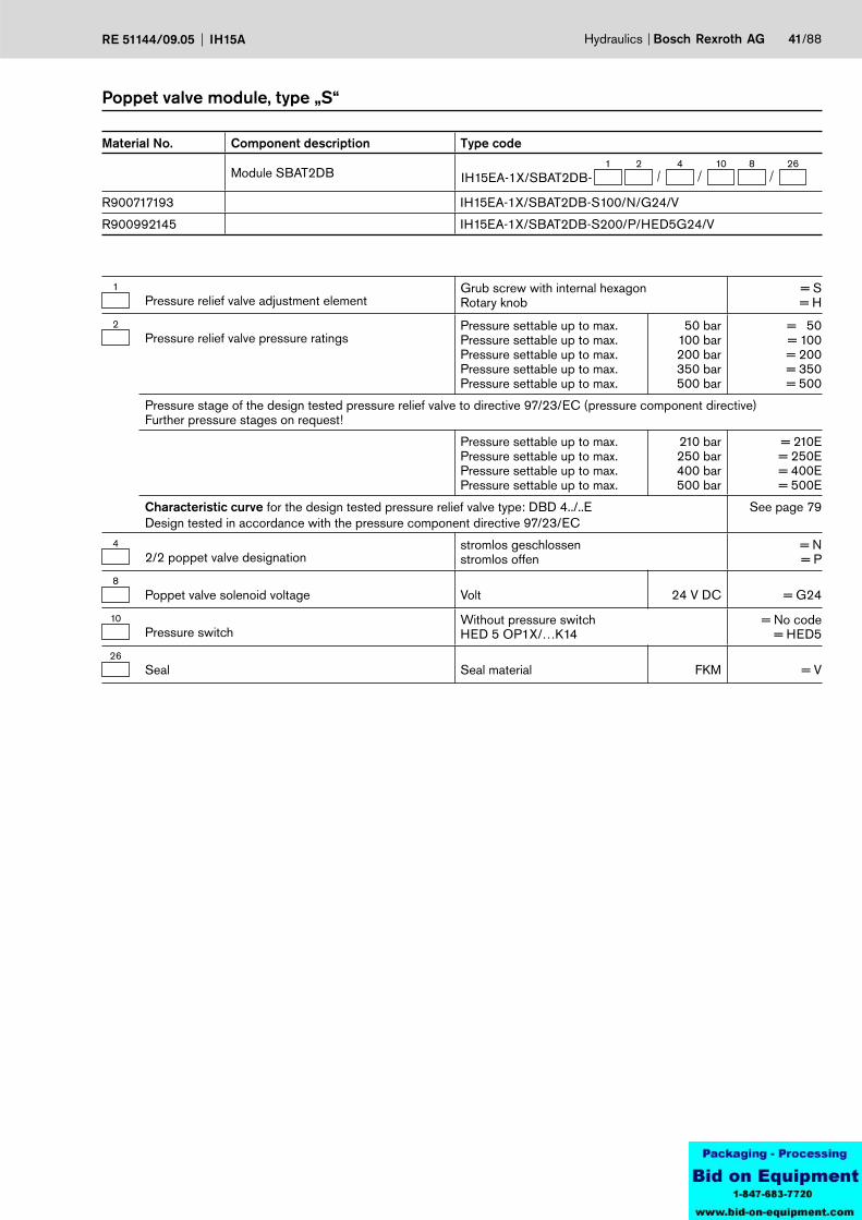
Hydraulics Bosch Rexroth AGRE 51144/09.05 IH15A 41/88
Material No. Component description Type code
Module SBAT2DB1 2 26
IH15EA-1X/SBAT2DB-8104
R900717193 IH15EA-1X/SBAT2DB-S100/N/G24/V
R900992145 IH15EA-1X/SBAT2DB-S200/P/HED5G24/V
Poppet valve module, type „S“
1Pressure relief valve adjustment element
Grub screw with internal hexagon Rotary knob
= S= H
2Pressure relief valve pressure ratings
Pressure settable up to max.Pressure settable up to max.Pressure settable up to max.Pressure settable up to max.Pressure settable up to max.
50 bar100 bar200 bar350 bar500 bar
= 50= 100= 200= 350= 500
Pressure stage of the design tested pressure relief valve to directive 97/23/EC (pressure component directive)Further pressure stages on request!
Pressure settable up to max.Pressure settable up to max.Pressure settable up to max.Pressure settable up to max.
210 bar250 bar400 bar500 bar
= 210E= 250E= 400E= 500E
Characteristic curve for the design tested pressure relief valve type: DBD 4../..EDesign tested in accordance with the pressure component directive 97/23/EC
See page 79
42/2 poppet valve designation
stromlos geschlossenstromlos offen
= N= P
8Poppet valve solenoid voltage Volt 24 V DC = G24
10Pressure switch
Without pressure switchHED 5 OP1X/…K14
= No code= HED5
26Seal Seal material FKM = V

25,5
43,5
13
Y
A
58,5
162
B 50
75
A
PT
a
b
B
P T
G1/4 G1/4
25,5
43,5
13
Y
A
B 50
75
136,5
240
HED5
A
PT
a
b
B
P T
G1/4 G1/4
42/88 Bosch Rexroth AG Hydraulics IH15A RE 51144/09.05
Symbol
Module P – B – A – T with pressure relief valve, type „SPBAT2DB“
Unit dimensions
Poppet valve module, type „S“ (nominal dimensions in mm)
Dim. Z = 45 mm
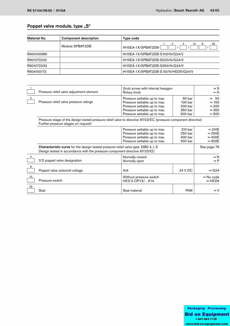
Hydraulics Bosch Rexroth AGRE 51144/09.05 IH15A 43/88
Material No. Component description Type code
Module SPBAT2DB1 2 26
IH15EA-1X/SPBAT2DB-8104
R904100985 IH15EA-1X/SPBAT2DB-S100/N/G24/V
R901072232 IH15EA-1X/SPBAT2DB-S200/N/G24/V
R901072233 IH15EA-1X/SPBAT2DB-S350/N/G24/V
R904100172 IH15EA-1X/SPBAT2DB-S 50/N/HED5/G24/V
Poppet valve module, type „S“
1Pressure relief valve adjustment element
Grub screw with internal hexagon Rotary knob
= S= H
2Pressure relief valve pressure ratings
Pressure settable up to max.Pressure settable up to max.Pressure settable up to max.Pressure settable up to max.Pressure settable up to max.
50 bar100 bar200 bar350 bar500 bar
= 50= 100= 200= 350= 500
Pressure stage of the design tested pressure relief valve to directive 97/23/EC (pressure component directive)Further pressure stages on request!
Pressure settable up to max.Pressure settable up to max.Pressure settable up to max.Pressure settable up to max.
210 bar250 bar400 bar500 bar
= 210E= 250E= 400E= 500E
Characteristic curve for the design tested pressure relief valve type: DBD 4../..EDesign tested in accordance with the pressure component directive 97/23/EC
See page 79
42/2 poppet valve designation
Normally closedNormally open
= N= P
8Poppet valve solenoid voltage Volt 24 V DC = G24
10Pressure switch
Without pressure switchHED 5 OP1X/…K14
= No code= HED5
26Seal Seal material FKM = V

A
M
25,5
43,5
58,5
162
13
Y
70
49
MA
PT
a
b
P
T
A
G1/4 G1/4
A
M
25,5
43,5
58,5
162
13
Y
70
49
HED5
240
MA
PT
a
b
G1/4 G1/4
P
T
A
A
M
25,5
43,5
58,5
Y70
162
272
HED8
13
49
44/88 Bosch Rexroth AG Hydraulics IH15A RE 51144/09.05
Symbol
Module P – A, type „SPA3“
Unit dimensions
Poppet valve module, type „S“ (nominal dimensions in mm)
Dim. Z = 45 mm

MA
PT
a
b
P
T
A
G1/4 G1/4
P1
MA
PT
a
b
P
T
A
G1/4 G1/4
P1
Hydraulics Bosch Rexroth AGRE 51144/09.05 IH15A 45/88
Symbol
Module P – A with P1 - port, type „SPA3P1“
Poppet valve module, type „S“

46/88 Bosch Rexroth AG Hydraulics IH15A RE 51144/09.05
Poppet valve module, type „S“
53/2 poppet valve designation
A
P T
= U
A
P T
= C
7Poppet valve pressure rating
pmax pmax
= 350 bar= 500 bar
= 350 1)
= 500 1)
8Poppet valve solenoid voltage Volt 24 V DC = G24
11Pressure switch
Without pressure switchHED 5 OP1X/…K14HED 8 OP1X/…K15
= No code= HED 5= HED 8
12Pressure switch pressure stage
Without pressure switchMax. settable pressureMax. settable pressureMax. settable pressureMax. settable pressureMax. settable pressureMax. settable pressure
50 bar100 bar200 bar210 bar350 bar630 bar
= No code= 50
= 100= 200 2)
= 210 3)
= 350= 630
14Pressure monitoring
With pressure gauge NS63With test pointWithout pressure monitoring
= D= M= O
26Seal Seal material FKM = V
1) Details are only required, when the module does not have any pressure switches fitted.
2) Only valid for HED 83) Only valid for HED 5
Material No. Component description Type code
Module SPA3P1IH15EA-1X/SPA3P1-
5 11 12 14 8 7 26
R904101002 IH15EA-1X/SPA3P1-C/MG24/350/V
R904100789 IH15EA-1X/SPA3P1-CHED5/100/OG24/V
R901100035 IH15EA-1X/SPA3P1-U/MG24/350/V
R904100879 IH15EA-1X/SPA3P1-UHED5/100/OG24/V
Material No. Component description Type code
Module SPA3IH15EA-1X/SPA3-
5 11 12 14 8 7 26
R900993540 IH15EA-1X/SPA3-C/MG24/350/V
R904100943 IH15EA-1X/SPA3-CHED5/350/MG24/V
R900993541 IH15EA-1X/SPA3-U/MG24/350/V
R900719081 IH15EA-1X/SPA3-UHED5/350/MG24/V
25,5
43,5
13
Y
A
58,5
162
56
85
M
A
PT
a
b
MG1/4 G1/4
P
T
A P T
25,5
43,5
13
Y
A
136,5
240
M 56
85
HED5
A
PT
a
b
MG1/4 G1/4
P A P T
T
25,5
43,5
13
Y
A
M 56
85
58,5
162
270
HED8
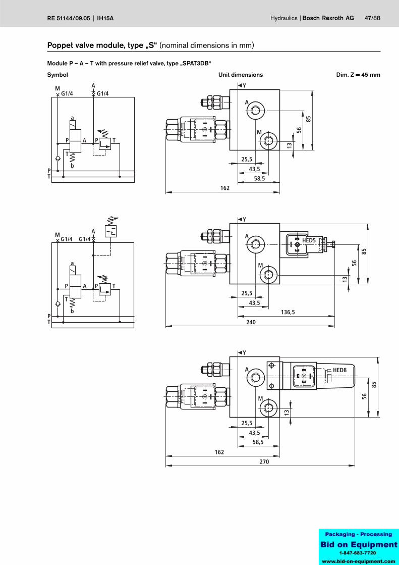
Hydraulics Bosch Rexroth AGRE 51144/09.05 IH15A 47/88
Symbol
Module P – A – T with pressure relief valve, type „SPAT3DB“
Unit dimensions
Poppet valve module, type „S“ (nominal dimensions in mm)
Dim. Z = 45 mm

48/88 Bosch Rexroth AG Hydraulics IH15A RE 51144/09.05
Material No. Component description Type code
Module SPAT3DBIH15EA-1X/SPAT3DB-
1 2 5 14 8 2611
R904101659 IH15EA-1X/SPAT3DB-S200CHED5/DG24/V
R901063501 IH15EA-1X/SPAT3DB-S200CHED5/MG24/V
R901100755 IH15EA-1X/SPAT3DB-S200CHED5/OG24/V
1Pressure relief valve adjustment element
Grub screw with internal hexagon Rotary knob
= S= H
2Pressure relief valve pressure ratings
Pressure settable up to max.Pressure settable up to max.Pressure settable up to max.Pressure settable up to max.Pressure settable up to max.
50 bar100 bar200 bar350 bar500 bar
= 50= 100= 200= 350= 500
Pressure stage of the design tested pressure relief valve to directive 97/23/EC (pressure component directive)Further pressure stages on request!
Pressure settable up to max.Pressure settable up to max.Pressure settable up to max.Pressure settable up to max.
210 bar250 bar400 bar500 bar
= 210E= 250E= 400E= 500E
Characteristic curve for the design tested pressure relief valve type: DBD 4../..EDesign tested in accordance with the pressure component directive 97/23/EC
See page 79
53/2 poppet valve designation
A
P T
= U
A
P T
= C
8Poppet valve solenoid voltage Volt 24 V DC = G24
11Pressure switch
Without pressure switchHED 5 OP1X/…K14HED 8 OP1X/…K15
= No code= HED 5= HED 8
14Pressure monitoring
With pressure gauge NS63With test pointWithout pressure monitoring
= D= M= O
26Seal Seal material FKM = V
Poppet valve module, type „S“
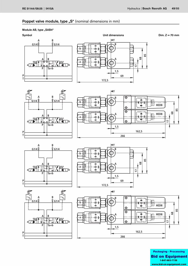
YB
A
1,5
69
172,5
85
68
17
b
a
A B
A B
P Ta+ba b
PT
G1/4 G1/4
Y
B
A
1,5
162,5
266
b
a
HED8
HED8
85
68
17
A B
A B
P Ta+ba b
PT
G1/4 G1/4
YB
A
1,5
69
172,5
85
68
17
b
a
Y
B
A
1,5
162,5
266
b
a
HED8
HED8
85
68
17
A B
A B
P Ta+ba b
PT
G1/4 G1/4
A B
A B
P Ta+ba b
PT
G1/4 G1/4
Hydraulics Bosch Rexroth AGRE 51144/09.05 IH15A 49/88
Symbol
Module AB, type „SAB4“
Unit dimensions
Poppet valve module, type „S“ (nominal dimensions in mm)
Dim. Z = 70 mm
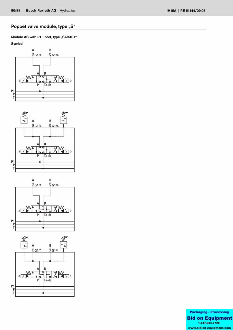
A B
A B
P Ta+ba b
PT
G1/4 G1/4
P1
A B
A B
P Ta+ba b
PT
G1/4 G1/4
P1
A B
P Ta+ba b
A B
PT
G1/4 G1/4
P1
A B
PT
G1/4 G1/4
P1
A B
P Ta+ba b
50/88 Bosch Rexroth AG Hydraulics IH15A RE 51144/09.05
Symbol
Module AB with P1 - port, type „SAB4P1“
Poppet valve module, type „S“
Hydraulics Bosch Rexroth AGRE 51144/09.05 IH15A 51/88
Poppet valve module, type „S“
1) Details are only required when the module does not have any pressure switches fitted.
2) Only valid for HED 83) Only valid for HED 5
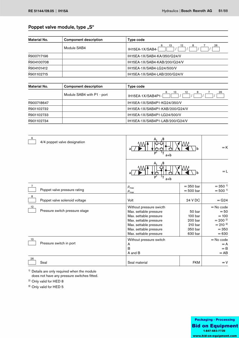
Material No. Component description Type code
Module SAB4 with P1 - port6 13 26
IH15EA-1X/SAB4P1-7812
R900718647 IH15EA-1X/SAB4P1-KG24/350/V
R901102732 IH15EA-1X/SAB4P1-KAB/200/G24/V
R901102733 IH15EA-1X/SAB4P1-LG24/500/V
R901102734 IH15EA-1X/SAB4P1-LAB/200/G24/V
64/4 poppet valve designation
a b
A B
P T a+b
= K
a b
A B
P T a+b
= L
7Poppet valve pressure rating
pmax pmax
= 350 bar= 500 bar
= 350 1)
= 500 1)
8Poppet valve solenoid voltage Volt 24 V DC = G24
12Pressure switch pressure stage
Without pressure swicthMax. settable pressureMax. settable pressureMax. settable pressureMax. settable pressureMax. settable pressureMax. settable pressure
50 bar100 bar200 bar210 bar350 bar630 bar
= No code= 50
= 100= 200 2)
= 210 3)
= 350= 630
13Pressure switch in port
Without pressure switchAB A and B
= No code= A= B
= AB26
Seal Seal material FKM = V
Material No. Component description Type code
Module SAB46 13 26
IH15EA-1X/SAB4-7812
R900717196 IH15EA-1X/SAB4-KA/350/G24/V
R904100708 IH15EA-1X/SAB4-KAB/200/G24/V
R904101412 IH15EA-1X/SAB4-LG24/500/V
R901102715 IH15EA-1X/SAB4-LAB/200/G24/V
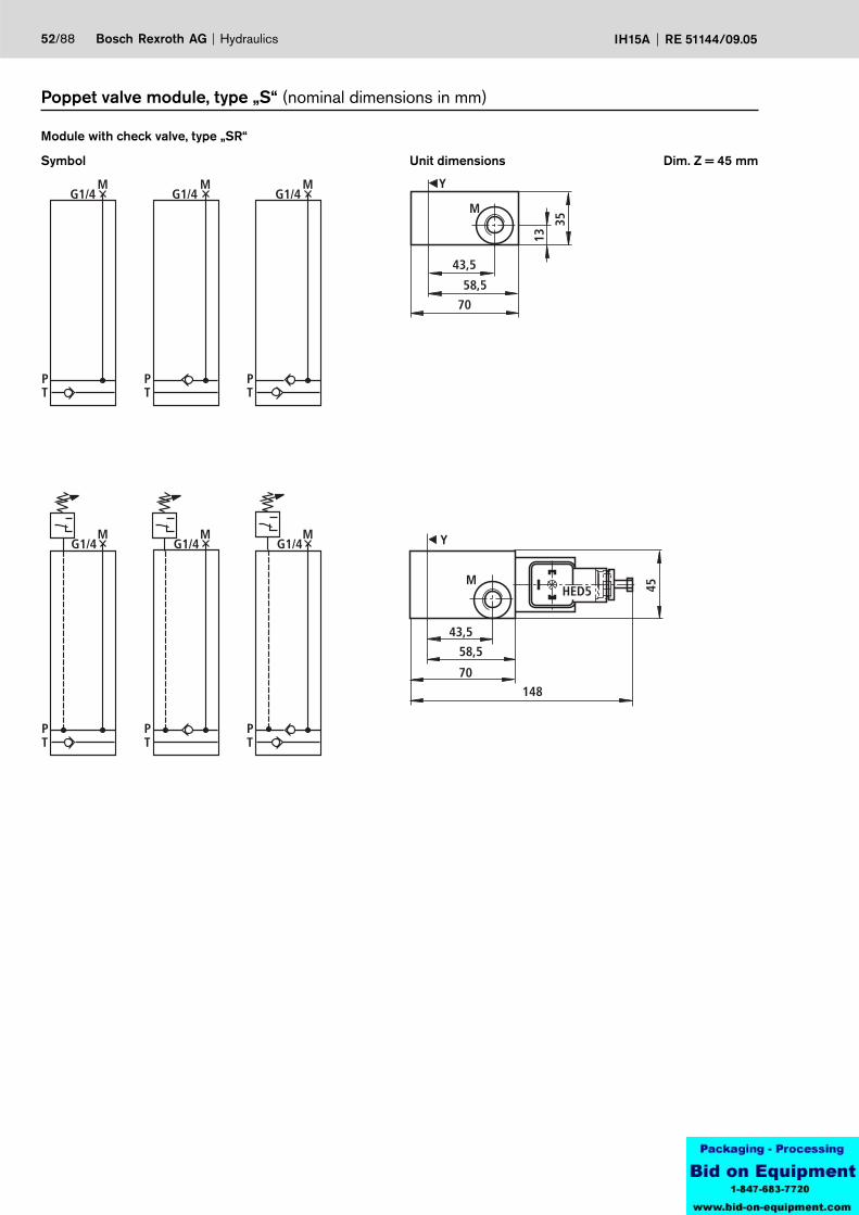
43,5
13
Y
58,5
M
35
70
M
PT
M
PT
M
PT
G1/4 G1/4 G1/4
70
Y
43,5
58,5
M
45
148
HED5
M
PT
M
PT
M
PT
G1/4 G1/4 G1/4
52/88 Bosch Rexroth AG Hydraulics IH15A RE 51144/09.05
Symbol
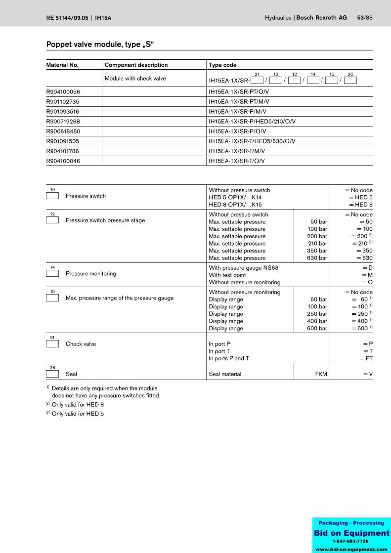
Module with check valve, type „SR“
Unit dimensions
Poppet valve module, type „S“ (nominal dimensions in mm)
Dim. Z = 45 mm
Hydraulics Bosch Rexroth AGRE 51144/09.05 IH15A 53/88
Poppet valve module, type „S“
1) Details are only required when the module does not have any pressure switches fitted.
2) Only valid for HED 83) Only valid for HED 5
Material No. Component description Type code
Module with check valve21 15
IH15EA-1X/SR-141210 26
R904100056 IH15EA-1X/SR-PT/O/V
R901102735 IH15EA-1X/SR-PT/M/V
R901093516 IH15EA-1X/SR-P/M/V
R900719268 IH15EA-1X/SR-P/HED5/210/O/V
R900618480 IH15EA-1X/SR-P/O/V
R901091505 IH15EA-1X/SR-T/HED5/630/O/V
R904101786 IH15EA-1X/SR-T/M/V
R904100046 IH15EA-1X/SR-T/O/V
10Pressure switch
Without pressure switchHED 5 OP1X/…K14HED 8 OP1X/…K15
= No code= HED 5= HED 8
12Pressure switch pressure stage
Without pressue switchMax. settable pressureMax. settable pressureMax. settable pressureMax. settable pressureMax. settable pressureMax. settable pressure
50 bar100 bar200 bar210 bar350 bar630 bar
= No code= 50
= 100= 200 2)
= 210 3)
= 350= 630
14Pressure monitoring
With pressure gauge NS63With test pointWithout pressure monitoring
= D= M= O
15Max. pressure range of the pressure gauge
Without pressure monitoringDisplay rangeDisplay rangeDisplay rangeDisplay rangeDisplay range
60 bar100 bar250 bar400 bar600 bar
= No code= 60 1)
= 100 1)
= 250 1)
= 400 1)
= 600 1)
21Check valve In port P
In port TIn ports P and T
= P= T
= PT26
Seal Seal material FKM = V
45
29
25,5
136,5226
M
Y
HED5HED5M
PT
G1/4
45
29
25,5168,5
290
M
Y
HED8
HED8
M
PT
G1/4
P1
54/88 Bosch Rexroth AG Hydraulics IH15A RE 51144/09.05
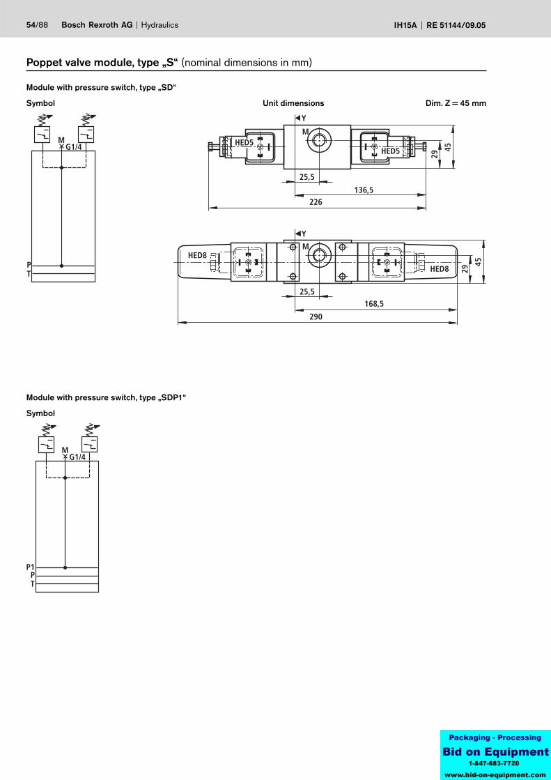
Symbol
Module with pressure switch, type „SD“
Unit dimensions
Poppet valve module, type „S“ (nominal dimensions in mm)
Dim. Z = 45 mm
Symbol
Module with pressure switch, type „SDP1“
Hydraulics Bosch Rexroth AGRE 51144/09.05 IH15A 55/88
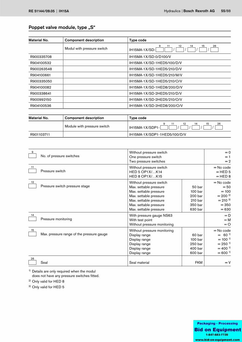
Poppet valve module, type „S“
1) Details are only required when the modul does not have any pressure switches fitted.
2) Only valid for HED 83) Only valid for HED 5
Material No. Component description Type code
Modul with pressure switch9 15
IH15MA-1X/SD-141211 26
R900335708 IH15MA-1X/SD-0/D100/V
R904100532 IH15MA-1X/SD-1HED5/100/D/V
R900263548 IH15MA-1X/SD-1HED5/210/D/V
R904100661 IH15MA-1X/SD-1HED5/210/M/V
R900335050 IH15MA-1X/SD-1HED5/210/O/V
R904100082 IH15MA-1X/SD-1HED8/200/D/V
R900338641 IH15MA-1X/SD-2HED5/210/D/V
R900992150 IH15MA-1X/SD-2HED5/210/O/V
R904100536 IH15MA-1X/SD-2HED8/200/O/V
Material No. Component description Type code
Module with pressure switch9 15
IH15MA-1X/SDP1-141211 26
R901103711 IH15MA-1X/SDP1-1HED5/100/D/V
9No. of pressure switches
Without pressure switchOne pressure switchTwo pressure switches
= 0= 1= 2
11Pressure switch
Without pressure switchHED 5 OP1X/…K14HED 8 OP1X/…K15
= No code= HED 5= HED 8
12Pressure switch pressure stage
Without pressure switchMax. settable pressureMax. settable pressureMax. settable pressureMax. settable pressureMax. settable pressureMax. settable pressure
50 bar100 bar200 bar210 bar350 bar630 bar
= No code= 50
= 100= 200 2)
= 210 3)
= 350= 630
14Pressure monitoring
With pressure gauge NS63With test pointWithout pressure monitoring
= D= M= O
15Max. pressure range of the pressure gauge
Without pressure monitoringDisplay rangeDisplay rangeDisplay rangeDisplay rangeDisplay range
60 bar100 bar250 bar400 bar600 bar
= No code= 60 1)
= 100 1)
= 250 1)
= 400 1)
= 600 1)
26Seal Seal material FKM = V
20
Y
58,5
70
PT
P1
56/88 Bosch Rexroth AG Hydraulics IH15A RE 51144/09.05
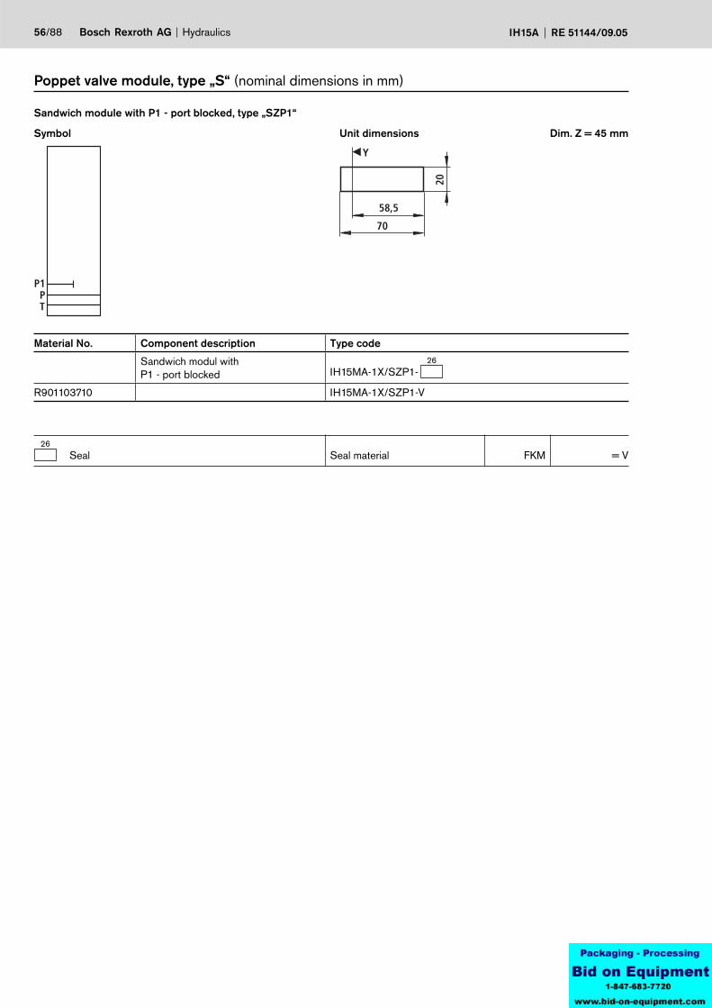
Symbol
Sandwich module with P1 - port blocked, type „SZP1“
Unit dimensions
Poppet valve module, type „S“ (nominal dimensions in mm)
Dim. Z = 45 mm
Material No. Component description Type code
Sandwich modul withP1 - port blocked
26IH15MA-1X/SZP1-
R901103710 IH15MA-1X/SZP1-V
26Seal Seal material FKM = V

PT
P
T
G1/4
G1/4
PT
58,5
70
10
Y Y
30
PT 1515
1,5
62,5
74
PT
P
T
G1/4
G1/4
P1PT
P1
Hydraulics Bosch Rexroth AGRE 51144/09.05 IH15A 57/88
Poppet valve module, type „S“ (Nennmaße in mm)
Symbol
End module with P1 - port, type „WSEP1“
22Ports
Without portsP and T: G 1/4
= No code= PT
26Seal Seal material FKM = V
Material No. Component description Type code
End module with P1 - port22
IH15MA-1X/WSEP1-26
R904101255 IH15MA-1X/WSEP1-V
Symbol
With ports P and T, on the sides
Symbol
End module, type „WSE“
Unit dimensions Dim. Z = 45 mm Symbol
With ports P and T, on the sides
Unit dimensions Dim. Z = 45 mm
Material No. Component description Type code
End module22
IH15MA-1X/WSE-26
R900334850 IH15MA-1X/WSE-PT/V
R900992158 IH15MA-1X/WSE-V
Y
58,5
158,5
147
247,5
136,
5
136,
5 153,
5HED8 HED8
M
PT
M
PT
G1/4
Y
58,5
148
136,5
226
163,
5
40
HED5 HED5
M
PT
M
PT
G1/4
M
PT
58/88 Bosch Rexroth AG Hydraulics IH15A RE 51144/09.05
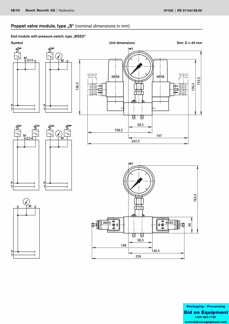
Symbol
End module with pressure switch, type „WSED“
Unit dimensions
Poppet valve module, type „S“ (nominal dimensions in mm)
Dim. Z = 45 mm

M
PT
M
PT
G1/4
P1 P1
M
PT
M
PT
G1/4
P1 P1
M
PT
P1
Hydraulics Bosch Rexroth AGRE 51144/09.05 IH15A 59/88
Symbol
End module with pressure switch and P1 - port, type „WSEDP1“
Poppet valve module, type „S“
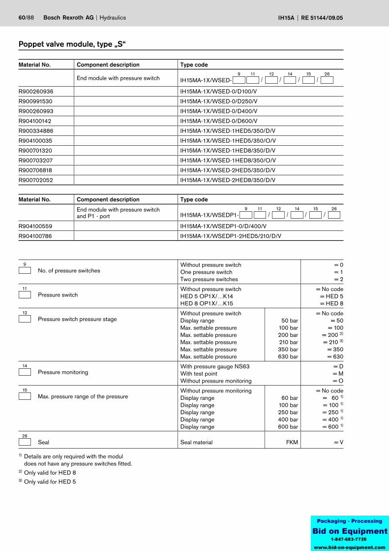
60/88 Bosch Rexroth AG Hydraulics IH15A RE 51144/09.05
Poppet valve module, type „S“
1) Details are only required with the modul does not have any pressure switches fitted.
2) Only valid for HED 83) Only valid for HED 5
Material No. Component description Type code
End module with pressure switch and P1 - port
9 15IH15MA-1X/WSEDP1-
141211 26
R904100559 IH15MA-1X/WSEDP1-0/D/400/V
R904100786 IH15MA-1X/WSEDP1-2HED5/210/D/V
9No. of pressure switches
Without pressure switchOne pressure switchTwo pressure switches
= 0= 1= 2
11Pressure switch
Without pressure switchHED 5 OP1X/…K14HED 8 OP1X/…K15
= No code= HED 5= HED 8
12Pressure switch pressure stage
Without pressure switchDisplay rangeMax. settable pressureMax. settable pressureMax. settable pressureMax. settable pressureMax. settable pressure
50 bar100 bar200 bar210 bar350 bar630 bar
= No code= 50
= 100= 200 2)
= 210 3)
= 350= 630
14Pressure monitoring
With pressure gauge NS63With test pointWithout pressure monitoring
= D= M= O
15Max. pressure range of the pressure
Without pressure monitoringDisplay rangeDisplay rangeDisplay rangeDisplay rangeDisplay range
60 bar100 bar250 bar400 bar600 bar
= No code= 60 1)
= 100 1)
= 250 1)
= 400 1)
= 600 1)
26Seal Seal material FKM = V
Material No. Component description Type code
End module with pressure switch9 15
IH15MA-1X/WSED-141211 26
R900260936 IH15MA-1X/WSED-0/D100/V
R900991530 IH15MA-1X/WSED-0/D250/V
R900260993 IH15MA-1X/WSED-0/D400/V
R904100142 IH15MA-1X/WSED-0/D600/V
R900334886 IH15MA-1X/WSED-1HED5/350/D/V
R904100035 IH15MA-1X/WSED-1HED5/350/O/V
R900701320 IH15MA-1X/WSED-1HED8/350/D/V
R900703207 IH15MA-1X/WSED-1HED8/350/O/V
R900706818 IH15MA-1X/WSED-2HED5/350/D/V
R900702052 IH15MA-1X/WSED-2HED8/350/D/V
58,5
141,
5
141,
5
163,
5
Y
158,5
147
247,5
M
PT
M
PT
G1/4
163,
5
58,5
Y
40
148136,5
226
M
PT
M
PT
G1/4
M
PT
Hydraulics Bosch Rexroth AGRE 51144/09.05 IH15A 61/88
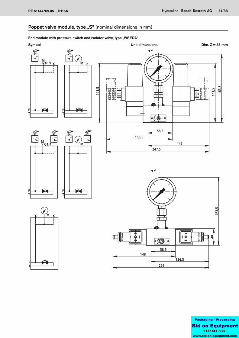
Symbol
End module with pressure switch and isolator valve, type „WSEDA“
Unit dimensions
Poppet valve module, type „S“ (nominal dimensions in mm)
Dim. Z = 55 mm
M
PT
M
PT
G1/4
P1 P1
M
PT
M
PT
G1/4
P1 P1
M
PT
P1
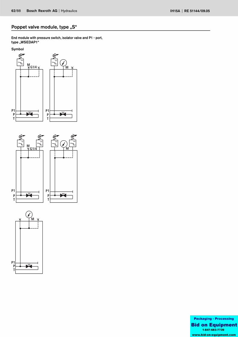
62/88 Bosch Rexroth AG Hydraulics IH15A RE 51144/09.05
Symbol
End module with pressure switch, isolator valve and P1 - port, type „WSEDAP1“
Poppet valve module, type „S“

Hydraulics Bosch Rexroth AGRE 51144/09.05 IH15A 63/88
Poppet valve module, type „S“
1) Details are only required when the modul does not have any pressrue switches fitted.
2) Only valid for HED 83) Only valid for HED 5
Material No. Component description Type code
End module with pressure switch, isolator valve and P1 - port
9 15IH15MA-1X/WSEDAP1-
141211 26
R901102912 IH15MA-1X/WSEDAP1-0/D/400/V
R901102913 IH15MA-1X/WSEDA-2HED5/210/D/V
9No. of pressure switches
Without pressure switchOne pressure switchTwo pressure switches
= 0= 1= 2
11Pressure switch
Without pressure switchHED 5 OP1X/…K14HED 8 OP1X/…K15
= No code= HED 5= HED 8
12Pressure switch pressure stage
Without pressure switchMax. settable pressureMax. settable pressureMax. settable pressureMax. settable pressureMax. settable pressureMax. settable pressure
50 bar100 bar200 bar210 bar350 bar630 bar
= No code= 50
= 100= 200 2)
= 210 3)
= 350= 630
14Pressure monitoring
With pressure gauge NS63With test pointWithout pressure monitoring
= D= M= O
15Max. pressure range of the pressure gauge
Without pressure monitoringDisplay rangeDisplay rangeDisplay rangeDisplay rangeDisplay range
60 bar100 bar250 bar400 bar600 bar
= No code= 60 1)
= 100 1)
= 250 1)
= 400 1)
= 600 1)
26Seal Seal material FKM = V
Material No. Component description Type code
End module with pressure switch and isolator valve
9 15IH15MA-1X/WSEDA-
141211 26
R904100815 IH15MA-1X/WSEDA-0/D/100/V
R901094566 IH15MA-1X/WSEDA-0/D/400/V
R904100208 IH15MA-1X/WSEDA-1HED5/100/D/V
R904101444 IH15MA-1X/WSEDA-1HED5/210/D/V
R904100040 IH15MA-1X/WSEDA-1HED5/210/O/V
R904100071 IH15MA-1X/WSEDA-1HED8/200/O/V
R904100675 IH15MA-1X/WSEDA-1HED8/350/D/V
R904100280 IH15MA-1X/WSEDA-2HED5/210/D/V
R901071162 IH15MA-1X/WSEDA-2HED8/200/D/V
Y
max
. 177
58,5
93
193,5
40
PT
136,5
226
40
max
. 177
Y
PT
64/88 Bosch Rexroth AG Hydraulics IH15A RE 51144/09.05
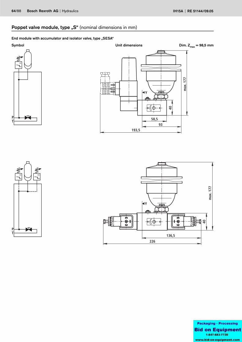
Symbol
End module with accumulator and isolator valve, type „SESA“
Unit dimensions Dim. Zmax = 98,5 mm
Poppet valve module, type „S“ (nominal dimensions in mm)
PT
P1
PT
P1
Hydraulics Bosch Rexroth AGRE 51144/09.05 IH15A 65/88
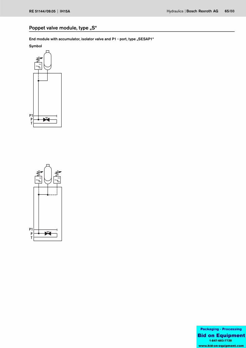
Symbol
End module with accumulator, isolator valve and P1 - port, type „SESAP1“
Poppet valve module, type „S“
66/88 Bosch Rexroth AG Hydraulics IH15A RE 51144/09.05
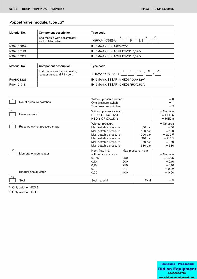
Poppet valve module, type „S“
2) Only valid for HED 83) Only valid for HED 5
Material No. Component description Type code
End module with accumulator, isolator valve and P1 - port
9 26IH15MA-1X/SESAP1-
181211
R901098223 IH15MA-1X/SESAP1-1HED5/100/0,32/V
R904101711 IH15MA-1X/SESAP1-2HED5/350/0,50/V
9No. of pressure switches
Without pressure switchOne pressure switchTwo pressure switches
= 0= 1= 2
11Pressure switch
Without pressure switchHED 5 OP1X/…K14HED 8 OP1X/…K15
= No code= HED 5= HED 8
12Pressure switch pressure stage
Without pressureMax. settable pressureMax. settable pressureMax. settable pressureMax. settable pressureMax. settable pressureMax. settable pressure
50 bar100 bar200 bar210 bar350 bar630 bar
= No code= 50
= 100= 200 2)
= 210 3)
= 350= 630
18Membrane accumulator
Bladder accumulator
Nom. flow in Lwithout accumulator0,0750,100,160,320,50
Max. pressure in bar
250500250210400
= No code= 0,075
= 0,10= 0,16= 0,32= 0,50
26Seal Seal material FKM = V
Material No. Component description Type code
End module with accumulator and isolator valve
9 26IH15MA-1X/SESA-
181211
R904100869 IH15MA-1X/SESA-0/0,32/V
R904100193 IH15MA-1X/SESA-1HED5/210/0,32/V
R904100921 IH15MA-1X/SESA-2HED5/210/0,32/V
PT
M
P
T
G1/4
12
max
. 192
50,5 93
Y
65
2
1
PT
M
P
T
G1/4
P1
12
Hydraulics Bosch Rexroth AGRE 51144/09.05 IH15A 67/88
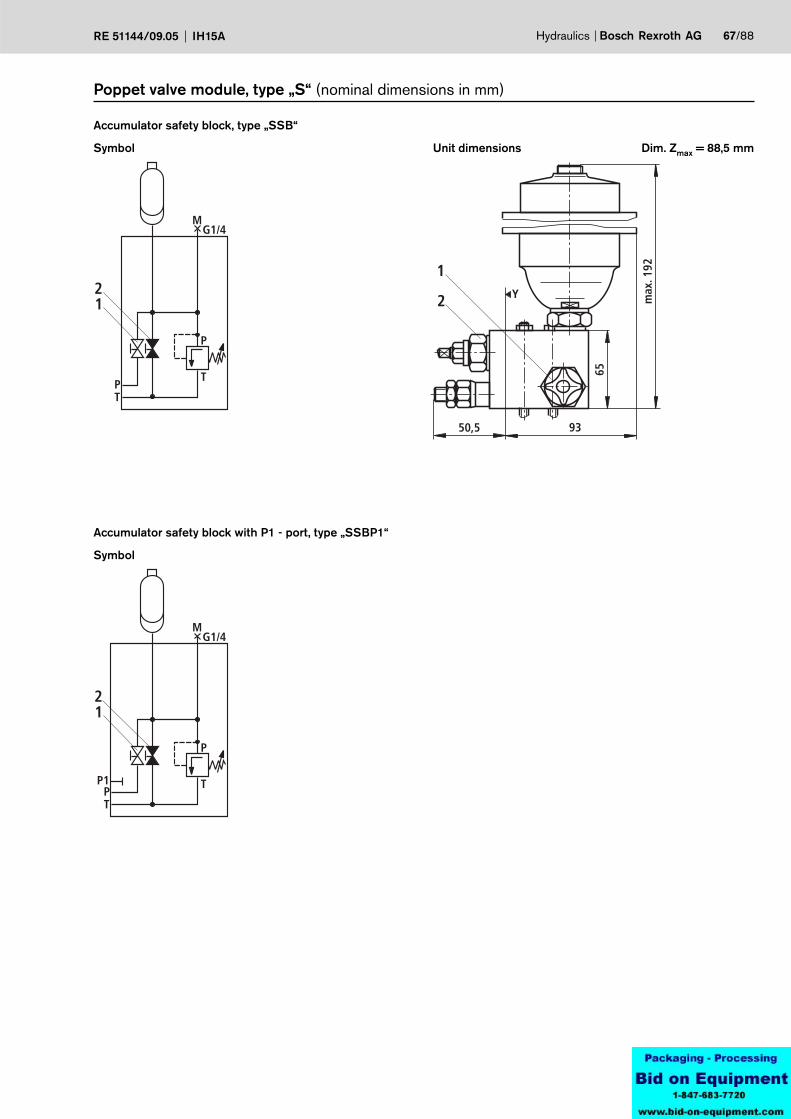
Symbol
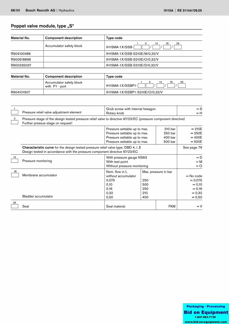
Accumulator safety block, type „SSB“
Unit dimensions Dim. Zmax = 88,5 mm
Poppet valve module, type „S“ (nominal dimensions in mm)
Symbol
Accumulator safety block with P1 - port, type „SSBP1“
68/88 Bosch Rexroth AG Hydraulics IH15A RE 51144/09.05
Poppet valve module, type „S“
Material No. Component description Type code
Accumulator safety block1 26
IH15MA-1X/SSB-18143
R904100486 IH15MA-1X/SSB-S210E/M/0,32/V
R900618898 IH15MA-1X/SSB-S210E/O/0,32/V
R900335037 IH15MA-1X/SSB-S210E/D/0,32/V
Material No. Component description Type code
Accumulator safety block with P1 - port
1 26IH15MA-1X/SSBP1-
18143
R904101907 IH15MA-1X/SSBP1-S210E/O/0,32/V
1Pressure relief valve adjustment element
Grub screw with internal hexagon Rotary knob
= S= H
3 Pressure stage of the design tested pressure relief valve to directive 97/23/EC (pressure component directive)Further pressue stage on request!
Pressure settable up to max.Pressure settable up to max.Pressure settable up to max.Pressure settable up to max.
210 bar250 bar400 bar500 bar
= 210E= 250E= 400E= 500E
Characteristic curve for the design tested pressure relief valve type: DBD 4../..EDesign tested in accordance with the pressure component directive 97/23/EC
See page 79
14Pressure monitoring
With pressure gauge NS63With test pointWithout pressure monitoring
= D= M= O
18Membrane accumulator
Bladder accumulator
Nom. flow in Lwithout accumulator0,0750,100,160,320,50
Max. pressure in bar
250500250210400
= No code= 0,075
= 0,10= 0,16= 0,32= 0,50
26Seal Seal material FKM = V
a
b
P T
PT
M
a
b
P T
a
b
P T
MA AA
a
b
P
T
A
M
P
T
a
b
P T
AB
P T
a
b
P T
A
a
b
P T
M
PT
a
b
P T
a
b
P T
AM
A
a
b
P T
a
b
P T
a
b
P T
MA
PT
BA
A B
P T
a b
PT
a
b
P T
AB
P T
Hydraulics Bosch Rexroth AGRE 51144/09.05 IH15A 69/88
Module for separate mounting: application with an application example
2 4
1 Connection module type A (see page 70)
2 Connection module with pressure relief valve type ADB (see page 71)
3 End module type E (see page 73)
4 Sandwich module type Z (page 72)The sandwich module can be combined with the connection module Pos. 1 or with the end module Pos. 3.
The length dimension is obtained by the addition of dim. „X“ of the directional valve modules (see pages 17 to 18) and the poppe valve modules (see pages 29 to 68).
1 3

PT
G1/4
G1/4
10
10
12
22
30 13,5
31,5
45
90 65
25 M8
Ø6,
8
T
P
70/88 Bosch Rexroth AG Hydraulics IH15A RE 51144/09.05
Module for separate mounting (nominal dimensions in mm)
Symbol
Connection module, type „A“
Unit dimensions
Material No. Component description Type code
Connection module26
IH15MA-1X/A-
R900993200 IH15MA-1X/A-V
26Seal Seal material FKM = V
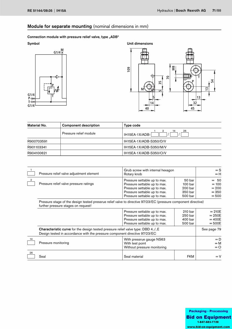
PT
M
P
T
G1/4
G1/4
G1/4
M
5
14
40
109
PT
45
13
32
70
M8
13
54
535
Hydraulics Bosch Rexroth AGRE 51144/09.05 IH15A 71/88
Module for separate mounting (nominal dimensions in mm)
Symbol
Connection module with pressure relief valve, type „ADB“
Unit dimensions
1Pressure relief valve adjustment element
Grub screw with internal hexagon Rotary knob
= S= H
2Pressure relief valve pressure ratings
Pressure settable up to max.Pressure settable up to max.Pressure settable up to max.Pressure settable up to max.Pressure settable up to max.
50 bar100 bar200 bar350 bar500 bar
= 50= 100= 200= 350= 500
Pressure stage of the design tested pressrue relief valve to directive 97/23/EC (pressure component directive)further pressure stages on request!
Pressure settable up to max.Pressure settable up to max.Pressure settable up to max.Pressure settable up to max.
210 bar250 bar400 bar500 bar
= 210E= 250E= 400E= 500E
Characteristic curve for the design tested pressure relief valve type: DBD 4../..EDesign tested in accordance with the pressure component directive 97/23/EC
See page 79
14Pressure monitoring
With pressrue gauge NS63With test pointWithout pressure monitoring
= D= M= O
26Seal Seal material FKM = V
Material No. Component description Type code
Pressure relief module1
IH15EA-1X/ADB-26142
R900703591 IH15EA-1X/ADB-S350/D/V
R901103341 IH15EA-1X/ADB-S350/M/V
R904100621 IH15EA-1X/ADB-S350/O/V
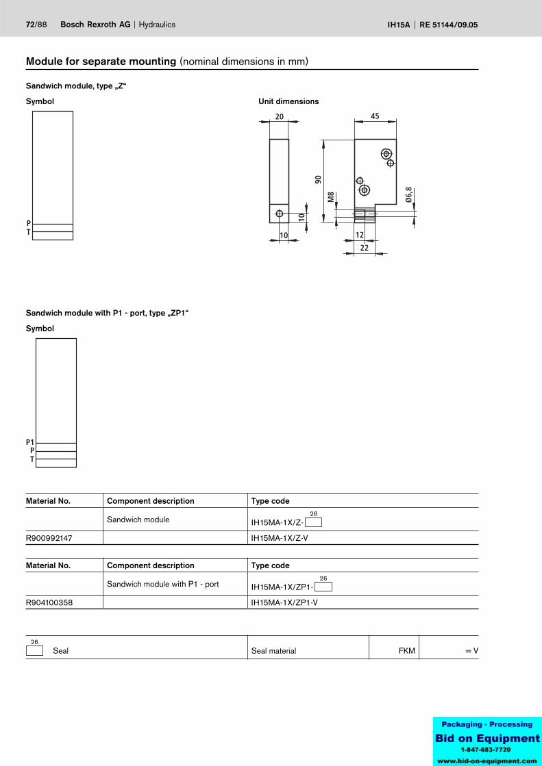
PT 12
22
45
90
M8
Ø6,
8
10
10
20
PT
P1
72/88 Bosch Rexroth AG Hydraulics IH15A RE 51144/09.05
Module for separate mounting (nominal dimensions in mm)
Symbol
Sandwich module, type „Z“
Unit dimensions
Material No. Component description Type code
Sandwich module26
IH15MA-1X/Z-
R900992147 IH15MA-1X/Z-V
26Seal Seal material FKM = V
Symbol
Sandwich module with P1 - port, type „ZP1“
Material No. Component description Type code
Sandwich module with P1 - port26
IH15MA-1X/ZP1-
R904100358 IH15MA-1X/ZP1-V

PT 12
22
45
90
M8
Ø6,
8
10
10
20
PT
P1
Hydraulics Bosch Rexroth AGRE 51144/09.05 IH15A 73/88
Module for separate mounting (nominal dimensions in mm)
Symbol
End module, type „E“
Unit dimensions
Material no. Component description Type code
End module26
IH15MA-1X/E-
R900993201 IH15MA-1X/E-V
26Seal Seal material FKM = V
Symbol
End module with P1 - port, type „EP1“
Material No. Component description Type code
End module with P1 - port26
IH15MA-1X/EP1-
R900262117 IH15MA-1X/EP1-V
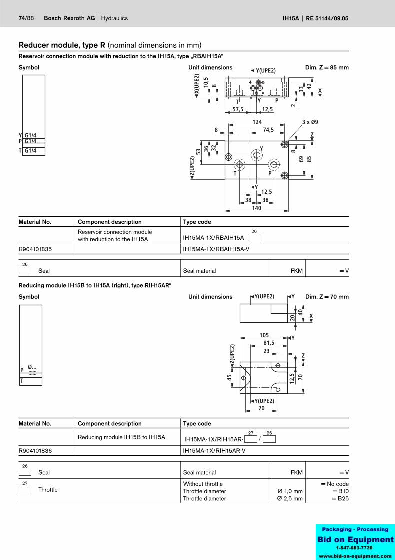
G1/4
G1/4P
T
Y G1/4
Y
Z
T P
Y
Z(U
PE2)
T PY
Y(UPE2)
X(U
PE2)
53 36 32
12474,58
12,53838
140
869 85
3 x Ø9
810,5
42332
12,557,5
X
T
P Ø...
Y
X2040
70
45
10581,523
7012
,5Y(UPE2)
Z(U
PE2)
Y(UPE2)
Y
Z
74/88 Bosch Rexroth AG Hydraulics IH15A RE 51144/09.05
Reducer module, type R (nominal dimensions in mm)
Symbol
Reservoir connection module with reduction to the IH15A, type „RBAIH15A“
Unit dimensions Dim. Z = 85 mm
Material No. Component description Type code
Reservoir connection module with reduction to the IH15A
26IH15MA-1X/RBAIH15A-
R904101835 IH15MA-1X/RBAIH15A-V
26Seal Seal material FKM = V
Material No. Component description Type code
Reducing module IH15B to IH15A IH15MA-1X/RIH15AR-2627
R904101836 IH15MA-1X/RIH15AR-V
26Seal Seal material FKM = V
27Throttle
Without throttleThrottle diameterThrottle diameter
Ø 1,0 mmØ 2,5 mm
= No code= B10= B25
Symbol
Reducing module IH15B to IH15A (right), type RIH15AR“
Unit dimensions Dim. Z = 70 mm
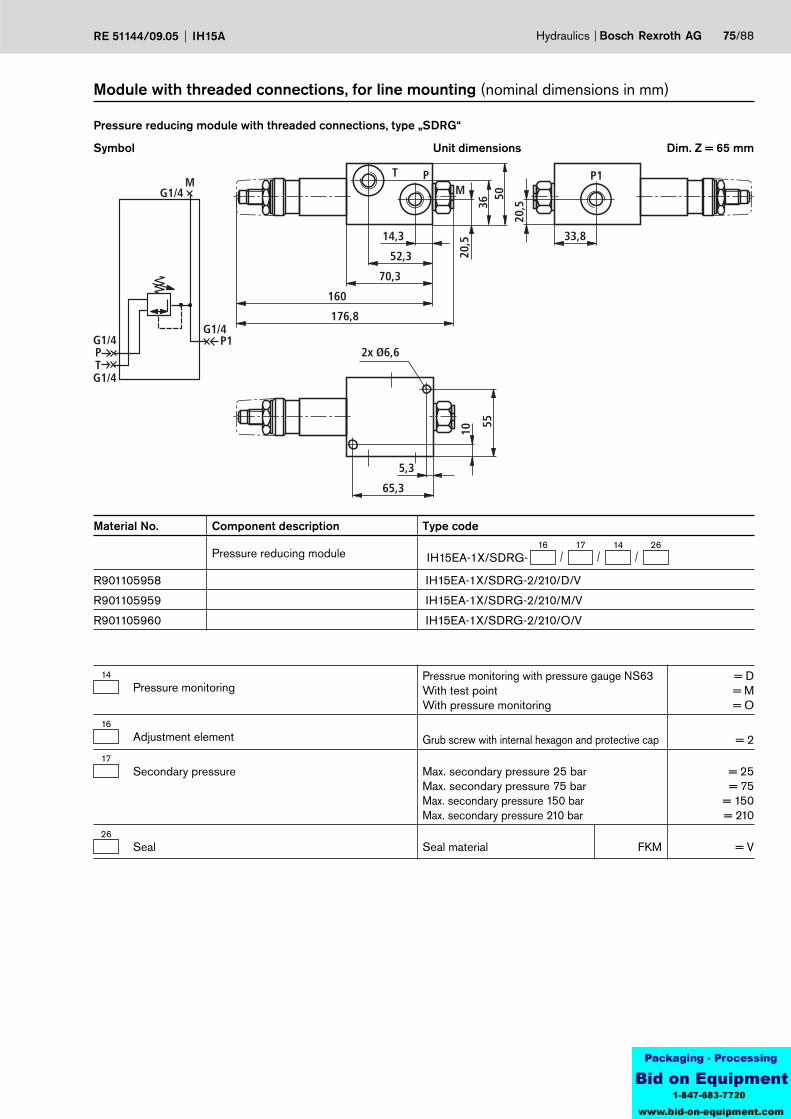
MG1/4
P1PT
G1/4
G1/4
G1/4
P1
20,5
33,8
T P
20,5
3650
14,3
52,3
70,3
160
176,8
2x Ø6,6
5,3
65,3
10
55
M
Hydraulics Bosch Rexroth AGRE 51144/09.05 IH15A 75/88
Module with threaded connections, for line mounting (nominal dimensions in mm)
Symbol
Pressure reducing module with threaded connections, type „SDRG“
Unit dimensions Dim. Z = 65 mm
Material No. Component description Type code
Pressure reducing module16 17 14 26
IH15EA-1X/SDRG-
R901105958 IH15EA-1X/SDRG-2/210/D/V
R901105959 IH15EA-1X/SDRG-2/210/M/V
R901105960 IH15EA-1X/SDRG-2/210/O/V
14Pressure monitoring
Pressrue monitoring with pressure gauge NS63With test pointWith pressure monitoring
= D= M= O
16Adjustment element
Grub screw with internal hexagon and protective cap = 2
17Secondary pressure Max. secondary pressure 25 bar
Max. secondary pressure 75 barMax. secondary pressure 150 barMax. secondary pressure 210 bar
= 25= 75
= 150= 210
26Seal Seal material FKM = V
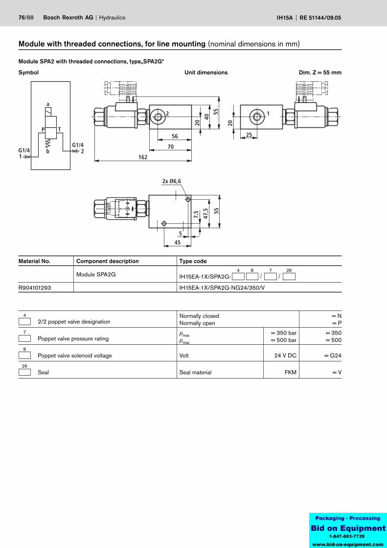
2 1
2x Ø6,6
56
70
162
20
40
55
20
25
5
45
7,5
47,5 55
1G1/4
G1/4
a
b
P T
2
76/88 Bosch Rexroth AG Hydraulics IH15A RE 51144/09.05
Symbol
Module SPA2 with threaded connections, type„SPA2G“
Unit dimensions
Module with threaded connections, for line mounting (nominal dimensions in mm)
Dim. Z = 55 mm
Material No. Component description Type code
Module SPA2G4 8 7 26
IH15EA-1X/SPA2G-
R904101293 IH15EA-1X/SPA2G-NG24/350/V
42/2 poppet valve designation
Normally closedNormally open
= N= P
7Poppet valve pressure rating
pmax pmax
= 350 bar= 500 bar
= 350= 500
8Poppet valve solenoid voltage Volt 24 V DC = G24
26Seal Seal material FKM = V
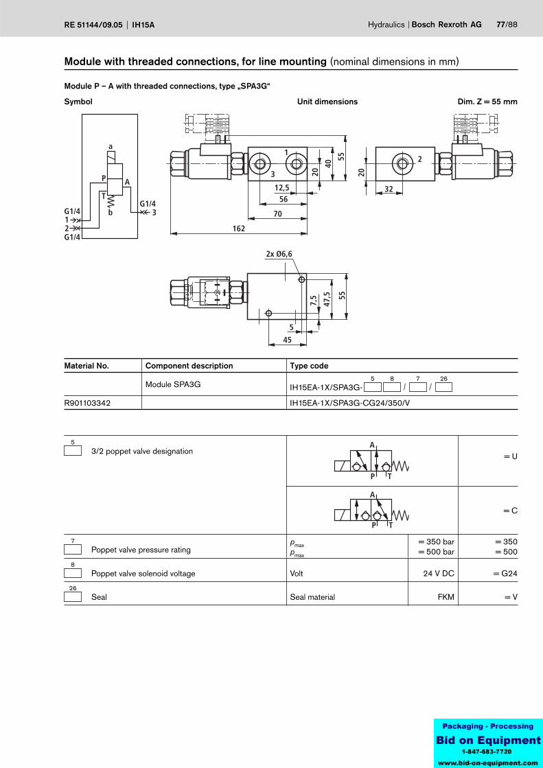
1
3
2
2x Ø6,6
12,556
70
162
20
40
55
20
32
5
45
7,5
47,5 55
12
G1/4
G1/4
G1/4
a
b
P
T
A
3
Hydraulics Bosch Rexroth AGRE 51144/09.05 IH15A 77/88
Symbol
Module P – A with threaded connections, type „SPA3G“
Unit dimensions
Module with threaded connections, for line mounting (nominal dimensions in mm)
Dim. Z = 55 mm
Material No. Component description Type code
Module SPA3G5 8 7 26
IH15EA-1X/SPA3G-
R901103342 IH15EA-1X/SPA3G-CG24/350/V
53/2 poppet valve designation
A
P T
= U
A
P T
= C
7Poppet valve pressure rating
pmax pmax
= 350 bar= 500 bar
= 350= 500
8Poppet valve solenoid voltage Volt 24 V DC = G24
26Seal Seal material FKM = V

78/88 Bosch Rexroth AG Hydraulics IH15A RE 51144/09.05
Type key details (nominal dimensions in mm)
1Pressure relief valve adjustment element NS4
Grub screw with internal hexagon
= S
50,5
Y
Rotary knob
= H
67,5
Y
Pressure relief valve adjustment element NS6Grub screw with hexagon and protective cap
= SØ34
72
Rotary knob
= HØ60
11 83
Lockable rotary knob
= A
8311
Ø60
28
20 28
2Pressure relief valve pressure ratings NS4
Pressure settable up to max.Pressure settable up to max.Pressure settable up to max.Pressure settable up to max.Pressure settable up to max.
50 bar100 bar200 bar350 bar500 bar
= 50= 100= 200= 350= 500
Pressure stage of the design tested pressure relief valve to directive NG4 97/23/EC (pressure component directive)Further pressure stages on request!
Pressure settable up to max.Pressure settable up to max.Pressure settable up to max.Pressure settable up to max.Pressure settable up to max.Pressure settable up to max.
140 bar210 bar250 bar330 bar400 bar500 bar
= 140E= 210E= 250E= 330E= 400E= 500E
Characteristic curve for the design tested pressure relief valve type: DBD 4../..EDesign tested in accordance with the pressure component directive 97/23/EC
See page 79
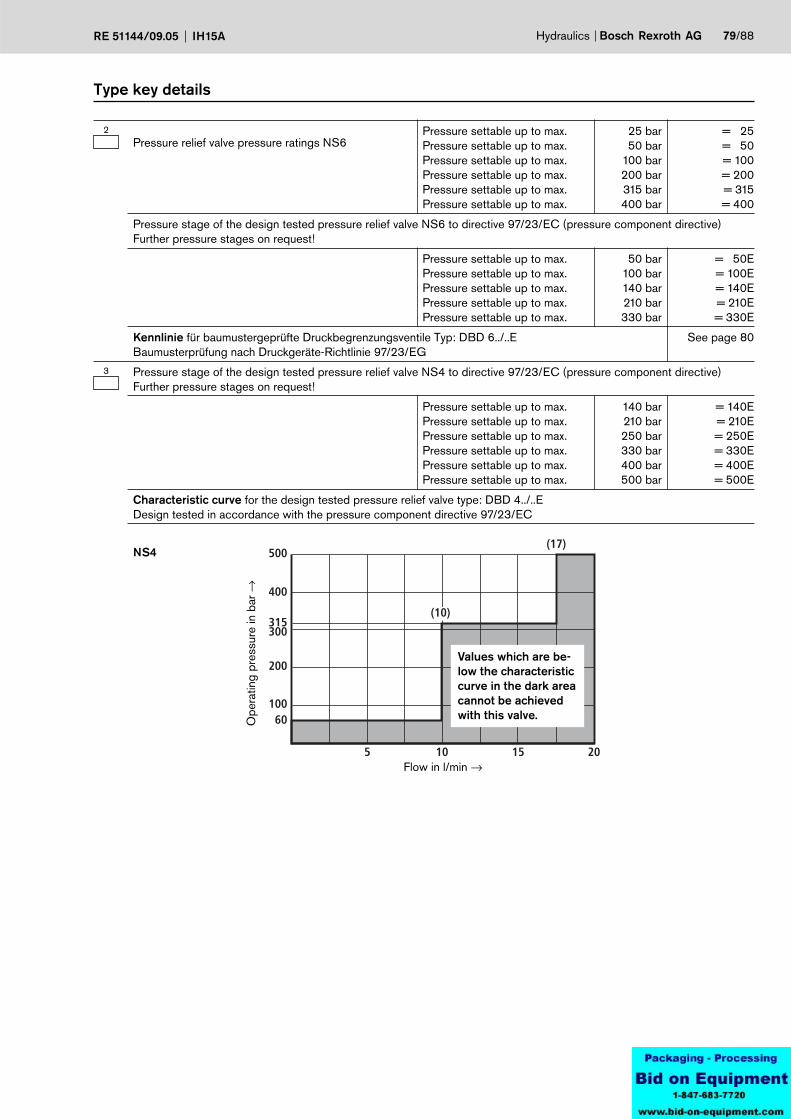
500
400
315300
200
10060
5 10 15 20
(10)
(17)
Hydraulics Bosch Rexroth AGRE 51144/09.05 IH15A 79/88
Type key details
2Pressure relief valve pressure ratings NS6
Pressure settable up to max.Pressure settable up to max.Pressure settable up to max.Pressure settable up to max.Pressure settable up to max.Pressure settable up to max.
25 bar50 bar
100 bar200 bar315 bar400 bar
= 25= 50= 100= 200= 315= 400
Pressure stage of the design tested pressure relief valve NS6 to directive 97/23/EC (pressure component directive)Further pressure stages on request!
Pressure settable up to max.Pressure settable up to max.Pressure settable up to max.Pressure settable up to max.Pressure settable up to max.
50 bar100 bar140 bar210 bar330 bar
= 50E= 100E= 140E= 210E= 330E
Kennlinie für baumustergeprüfte Druckbegrenzungsventile Typ: DBD 6../..EBaumusterprüfung nach Druckgeräte-Richtlinie 97/23/EG
See page 80
3 Pressure stage of the design tested pressure relief valve NS4 to directive 97/23/EC (pressure component directive)Further pressure stages on request!
Pressure settable up to max.Pressure settable up to max.Pressure settable up to max.Pressure settable up to max.Pressure settable up to max.Pressure settable up to max.
140 bar210 bar250 bar330 bar400 bar500 bar
= 140E= 210E= 250E= 330E= 400E= 500E
Characteristic curve for the design tested pressure relief valve type: DBD 4../..EDesign tested in accordance with the pressure component directive 97/23/EC
Values which are be-low the characteristic curve in the dark area cannot be achieved with this valve.
Flow in l/min →
Ope
ratin
g pr
essu
re in
bar
→
NS4
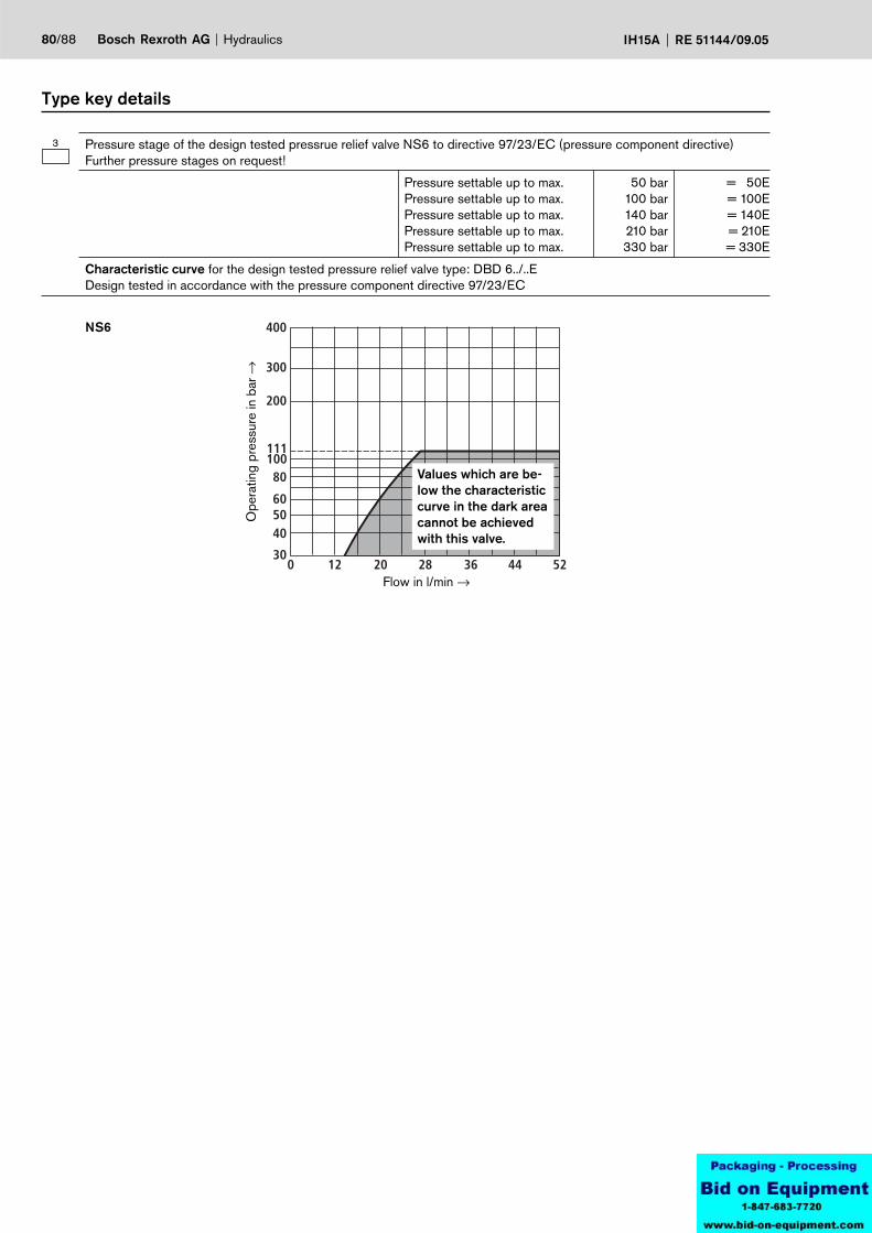
400
300
405060
80
200
300 12 20 28 36 44 52
100111
80/88 Bosch Rexroth AG Hydraulics IH15A RE 51144/09.05
Ope
ratin
g pr
essu
re in
bar
→
Flow in l/min →
Values which are be-low the characteristic curve in the dark area cannot be achieved with this valve.
Type key details
NS6
3 Pressure stage of the design tested pressrue relief valve NS6 to directive 97/23/EC (pressure component directive)Further pressure stages on request!
Pressure settable up to max.Pressure settable up to max.Pressure settable up to max.Pressure settable up to max.Pressure settable up to max.
50 bar100 bar140 bar210 bar330 bar
= 50E= 100E= 140E= 210E= 330E
Characteristic curve for the design tested pressure relief valve type: DBD 6../..EDesign tested in accordance with the pressure component directive 97/23/EC
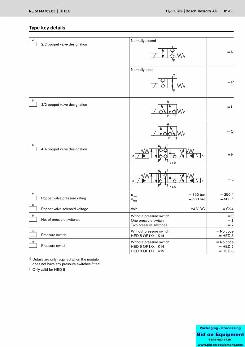
Hydraulics Bosch Rexroth AGRE 51144/09.05 IH15A 81/88
42/2 poppet valve designation
Normally closed
= N
T
P
Normally open
= P
T
P
53/2 poppet valve designation
A
P T
= U
A
P T
= C
64/4 poppet valve designation
a b
A B
P T a+b
= K
a b
A B
P T a+b
= L
7Poppet valve pressure rating
pmax pmax
= 350 bar= 500 bar
= 350 1)
= 500 1)
8Poppet valve solenoid voltage Volt 24 V DC = G24
9No. of pressure switches
Without pressure switchOne pressure switchTwo pressure switches
= 0= 1= 2
10Pressure switch
Without pressure switchHED 5 OP1X/…K14
= No code= HED 5
11Pressure switch
Without pressure switchHED 5 OP1X/…K14HED 8 OP1X/…K15
= No code= HED 5= HED 8
Type key details
1) Details are only required when the module does not have any pressure switches fitted.
3) Only valid for HED 5
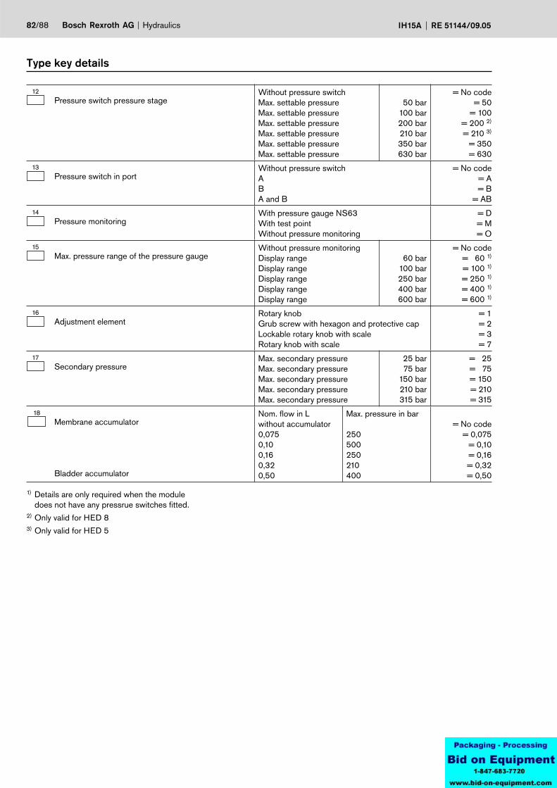
82/88 Bosch Rexroth AG Hydraulics IH15A RE 51144/09.05
Type key details
1) Details are only required when the module does not have any pressrue switches fitted.
2) Only valid for HED 83) Only valid for HED 5
12Pressure switch pressure stage
Without pressure switchMax. settable pressureMax. settable pressureMax. settable pressureMax. settable pressureMax. settable pressureMax. settable pressure
50 bar100 bar200 bar210 bar350 bar630 bar
= No code= 50
= 100= 200 2)
= 210 3)
= 350= 630
13Pressure switch in port
Without pressure switchAB A and B
= No code= A= B
= AB14
Pressure monitoringWith pressure gauge NS63With test pointWithout pressure monitoring
= D= M= O
15Max. pressure range of the pressure gauge
Without pressure monitoringDisplay rangeDisplay rangeDisplay rangeDisplay rangeDisplay range
60 bar100 bar250 bar400 bar600 bar
= No code= 60 1)
= 100 1)
= 250 1)
= 400 1)
= 600 1)
16Adjustment element
Rotary knobGrub screw with hexagon and protective capLockable rotary knob with scale Rotary knob with scale
= 1= 2 = 3= 7
17Secondary pressure
Max. secondary pressureMax. secondary pressureMax. secondary pressureMax. secondary pressureMax. secondary pressure
25 bar75 bar
150 bar210 bar315 bar
= 25= 75= 150= 210= 315
18Membrane accumulator
Bladder accumulator
Nom. flow in Lwithout accumulator0,0750,100,160,320,50
Max. pressure in bar
250500250210400
= No code= 0,075
= 0,10= 0,16= 0,32= 0,50
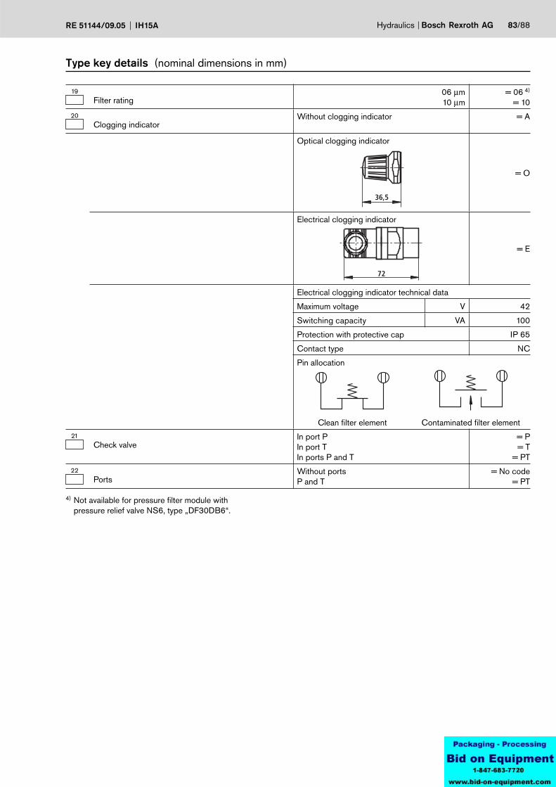
Hydraulics Bosch Rexroth AGRE 51144/09.05 IH15A 83/88
19Filter rating
06 µm10 µm
= 06 4)
= 1020
Clogging indicatorWithout clogging indicator = A
Optical clogging indicator
= O
36,5
Electrical clogging indicator
= E
72
Electrical clogging indicator technical data
Maximum voltage V 42
Switching capacity VA 100
Protection with protective cap IP 65
Contact type NC
Pin allocation
Clean filter element Contaminated filter element 21
Check valveIn port PIn port TIn ports P and T
= P= T
= PT22
PortsWithout portsP and T
= No code= PT
Type key details (nominal dimensions in mm)
4) Not available for pressure filter module with pressure relief valve NS6, type „DF30DB6“.
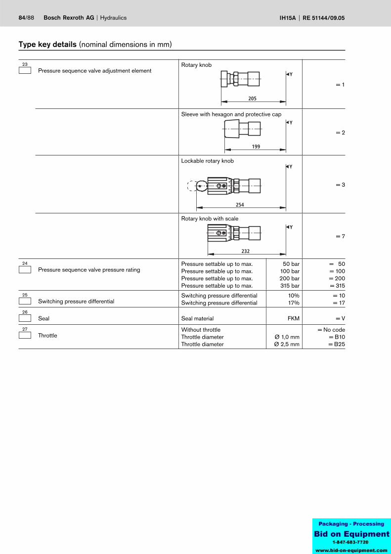
84/88 Bosch Rexroth AG Hydraulics IH15A RE 51144/09.05
23Pressure sequence valve adjustment element
Rotary knob
= 1
205
Y
Sleeve with hexagon and protective cap
= 2
199
Y
Lockable rotary knob
= 3
254
Y
Rotary knob with scale
= 7
232
Y
24Pressure sequence valve pressure rating
Pressure settable up to max. Pressure settable up to max. Pressure settable up to max. Pressure settable up to max.
50 bar100 bar200 bar315 bar
= 50= 100= 200= 315
25Switching pressure differential
Switching pressure differentialSwitching pressure differential
10%17%
= 10= 17
26Seal Seal material FKM = V
27Throttle
Without throttleThrottle diameterThrottle diameter
Ø 1,0 mmØ 2,5 mm
= No code= B10= B25
Type key details (nominal dimensions in mm)

24
20
16
12
830 35 40 45 50
24
20
16
12
850 60 80 90 10070
24
20
16
12
8200 220 260 300 320240 280
24
20
16
12
8100 120 160 200 210140 180
Hydraulics Bosch Rexroth AGRE 51144/09.05 IH15A 85/88
Pressure sequence valve
Suitable for use with flows qV ≥ 2 l/min
Example spread at a pressure switching differential of: 17% 10%
Pressure stage 50 bar
Sw
itchi
ng p
ress
ure
diffe
rent
ial i
n %
→
Sequence pressure in bar →
Pressure stage 100 bar
Pressure stage 200 bar Pressure stage 315 bar
Sw
itchi
ng p
ress
ure
diffe
rent
ial i
n %
→
Sw
itchi
ng p
ress
ure
diffe
rent
ial i
n %
→S
witc
hing
pre
ssur
e di
ffere
ntia
l in
% →
Sequence pressure in bar →
Sequence pressure in bar → Sequence pressure in bar →
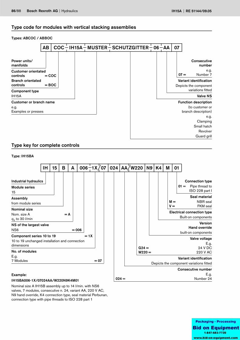
86/88 Bosch Rexroth AG Hydraulics IH15A RE 51144/09.05
Type code for modules with vertical stacking assemblies
Types: ABCOC / ABBOC
Type key for complete controls
Type: IH15BA
Power units/manifolds
Customer orientated controls = COCBranch orientated controls = BOC
Component typeIH15A
Customer or branch namee.g. Examples or presses
Consecutive number
e.g. 07 = Number 7
Variant identificationDepicts the component
variations fitted
Valve NS
Function description(to customer or
branch description)e.g.
ClampingSmall hatch
RevolverGuard grill
AB COC IH15A MUSTER SCHUTZGITTER 06 AA 07
Industrial hydraulics
Module series15
Assemblyfrom module series
Nominal size Nom. size A = AqV to 30 l/min
NS of the largest valveNS6 = 006
Component series 10 to 19 = 1X10 to 19 unchanged installation and connection dimensions
No. of modulesE.g. 7 Modules = 07
Connection type01 = Pipe thread to
ISO 228 part I
Seal materialM = NBR sealV = FKM seal
Electrical connection typeBuilt-on components
VersionHand override
built-on components
Valve voltageE.g.
G24 = 24 V DCW220 = 220 V AC
Variant identification Depicts the component variations fitted
Consecutive numberE.g.
024 = Number 24
IH 15 B A 006 1X 07 024 AA W220 N9 K4 M 01
Example:
IH15BA006-1X/07024AA/W220N9K4M01
Nominal size A IH15B assembly up to 14 l/min. with NS6 valves, 7 modules, consecutive n. 24, variant AA, 220 V AC, N9 hand override, K4 connection type, seal material Perbunan, connection type with pipe threads to ISO 228 part 1
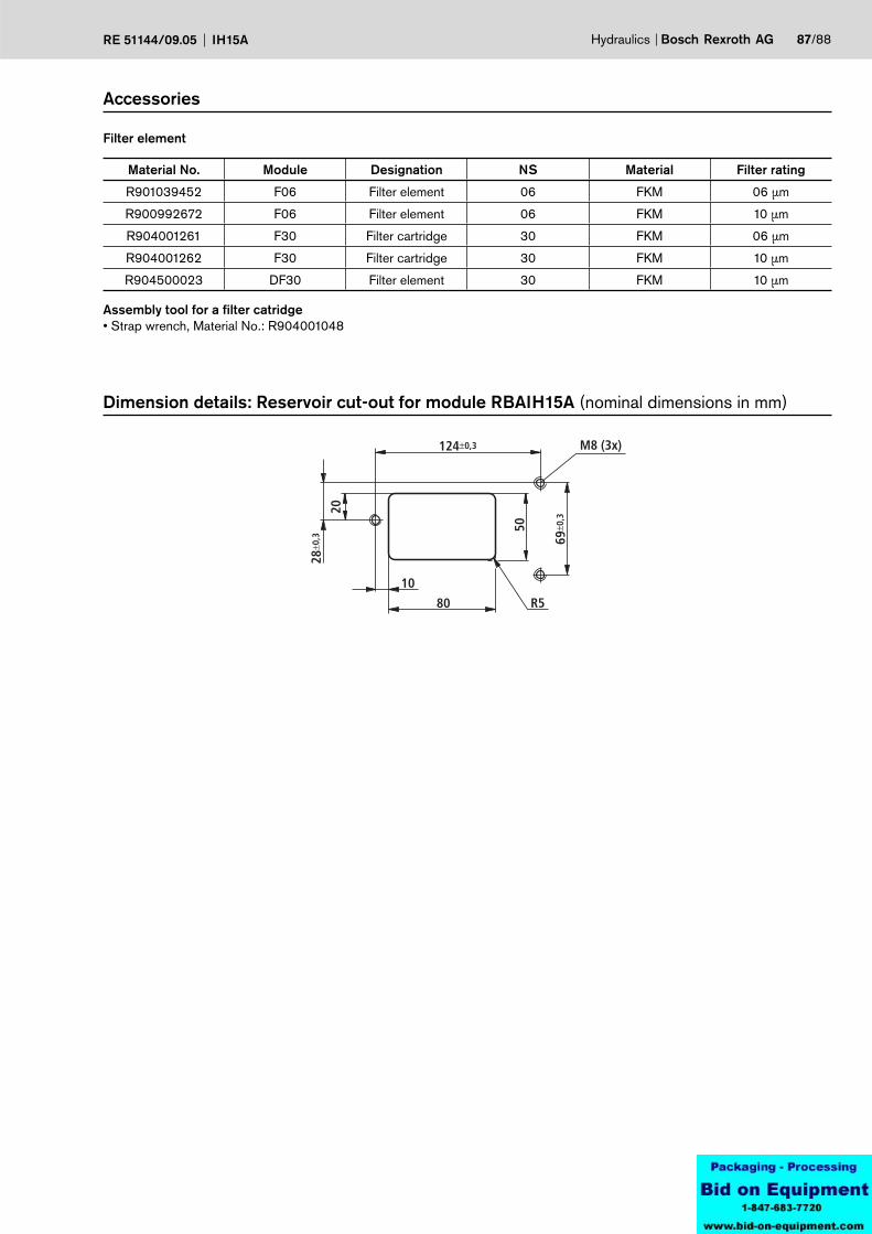
124±0,3
80
50
69±0
,3
R5
M8 (3x)
10
28±0
,3
20
Hydraulics Bosch Rexroth AGRE 51144/09.05 IH15A 87/88
Accessories
Filter element
Dimension details: Reservoir cut-out for module RBAIH15A (nominal dimensions in mm)
Material No. Module Designation NS Material Filter rating
R901039452 F06 Filter element 06 FKM 06 µm
R900992672 F06 Filter element 06 FKM 10 µm
R904001261 F30 Filter cartridge 30 FKM 06 µm
R904001262 F30 Filter cartridge 30 FKM 10 µm
R904500023 DF30 Filter element 30 FKM 10 µm
Assembly tool for a filter catridge• Strap wrench, Material No.: R904001048


