Current Transformer Theory & Testing
Jay Anderson – [email protected]
www.OmicronEnergy.com
Hands On Relay School 2016
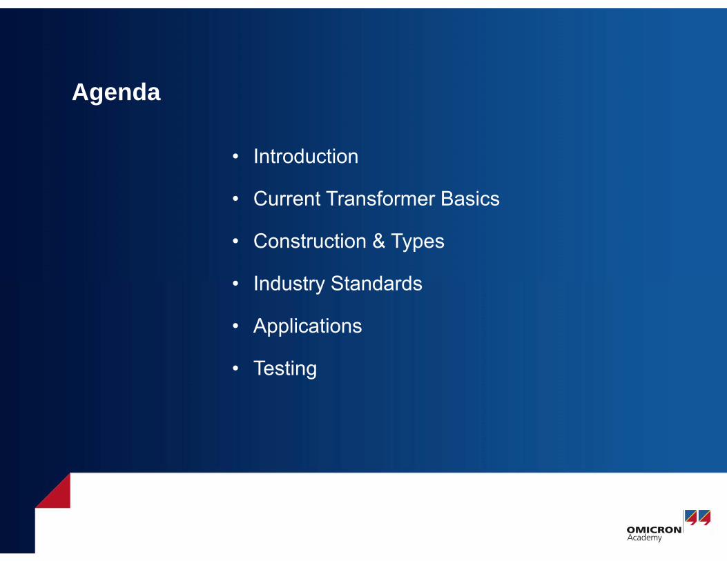
Agenda
• Introduction
• Current Transformer Basics
• Construction & Types
• Industry Standards
• Applications
• Testing
Current Transformer Basics
© OMICRON Page 3
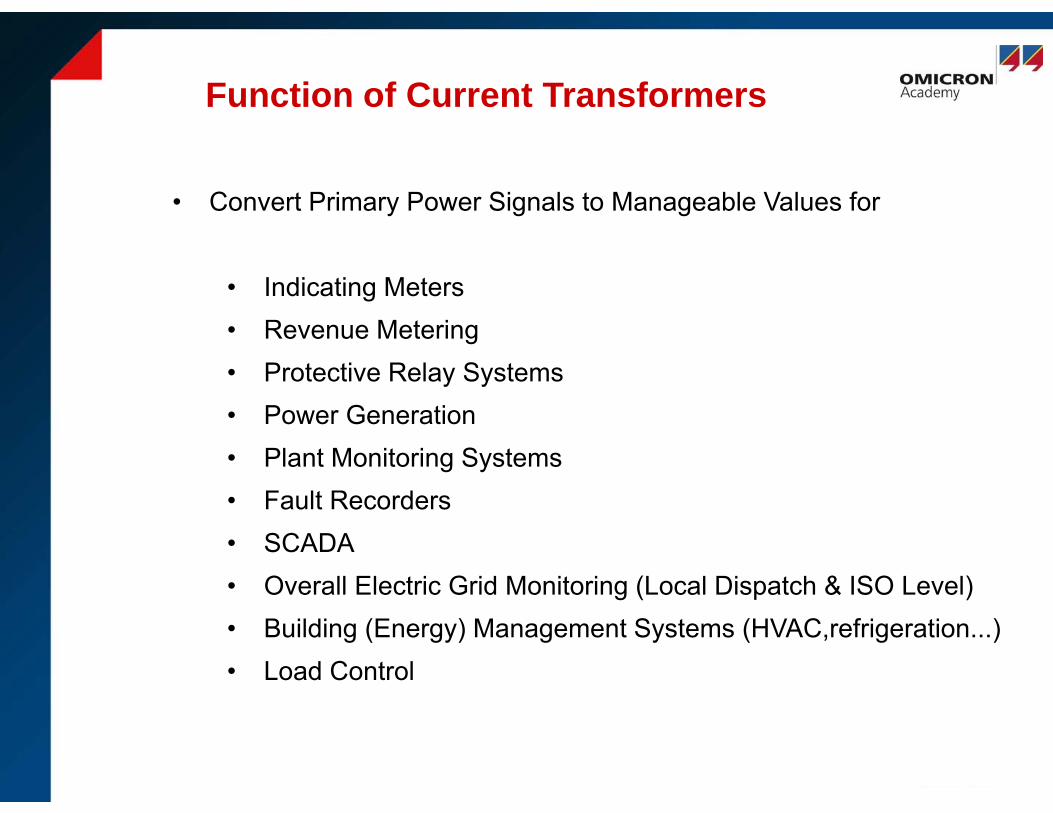
Function of Current Transformers
January 19, 2016 Page: 4
• Convert Primary Power Signals to Manageable Values for
• Indicating Meters• Revenue Metering• Protective Relay Systems• Power Generation• Plant Monitoring Systems• Fault Recorders• SCADA• Overall Electric Grid Monitoring (Local Dispatch & ISO Level)• Building (Energy) Management Systems (HVAC,refrigeration...)• Load Control

Current Transformers
January 19, 2016 Page: 5
• Insulation from High Voltages and Currents
• Isolation from other systems
• Safety
• Standardization
• Accuracy ( Ratio & Phase)
• Typically Low Power Rating
• Thermal Considerations
• Burden Considerations
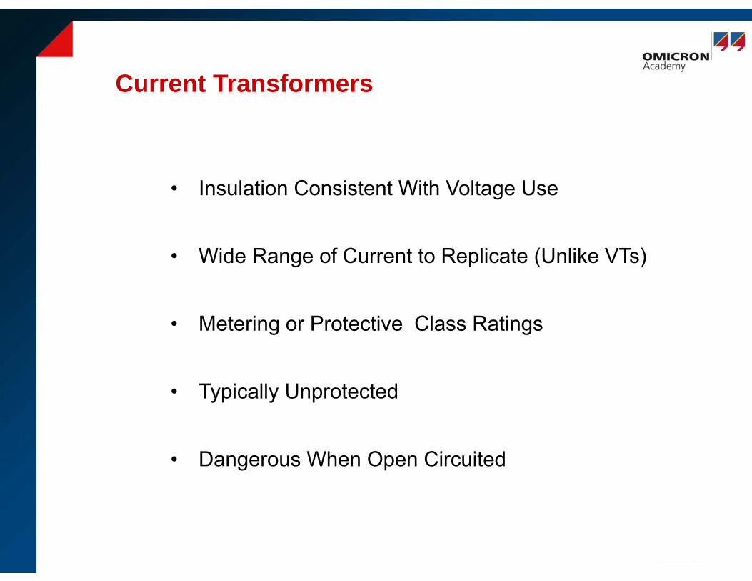
Current Transformers
January 19, 2016 Page: 6
• Insulation Consistent With Voltage Use
• Wide Range of Current to Replicate (Unlike VTs)
• Metering or Protective Class Ratings
• Typically Unprotected
• Dangerous When Open Circuited
Compliance & Standards
IEEE
ANSI
IEC in Europe & Asia
NERC Reliability Standards in US
Instrument Transformers Are Expected to Perform & Conform
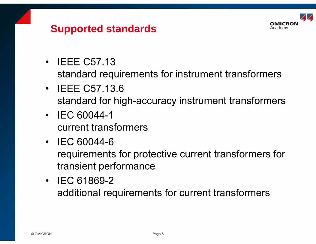
Supported standards
© OMICRON Page 8
• IEEE C57.13standard requirements for instrument transformers
• IEEE C57.13.6standard for high-accuracy instrument transformers
• IEC 60044-1current transformers
• IEC 60044-6requirements for protective current transformers for transient performance
• IEC 61869-2additional requirements for current transformers

Basic Transformer
~ Z
Ф
Ф
N2N1
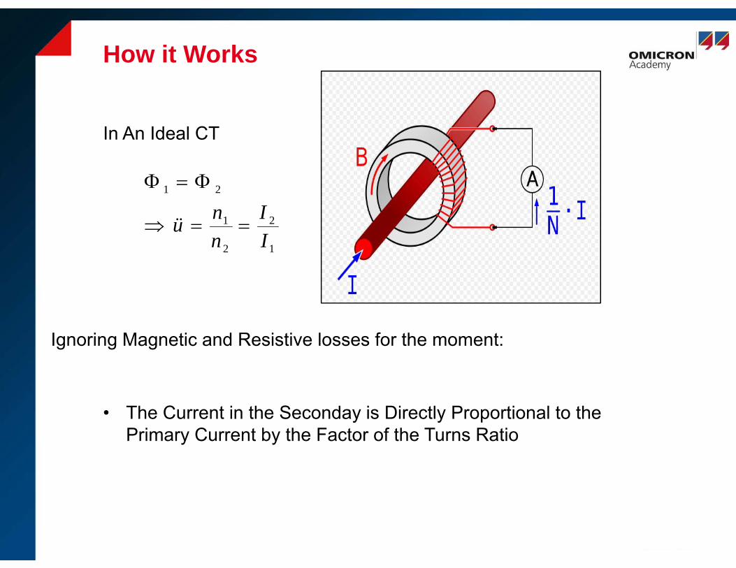
How it Works
Ignoring Magnetic and Resistive losses for the moment:
1
2
2
1
21
II
nnü
• The Current in the Seconday is Directly Proportional to thePrimary Current by the Factor of the Turns Ratio
In An Ideal CT
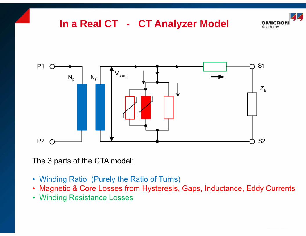
In a Real CT - CT Analyzer Model
The 3 parts of the CTA model:
• Winding Ratio (Purely the Ratio of Turns)• Magnetic & Core Losses from Hysteresis, Gaps, Inductance, Eddy Currents• Winding Resistance Losses
ZBLm
P1
P2 S2
S1VcoreNp Ns
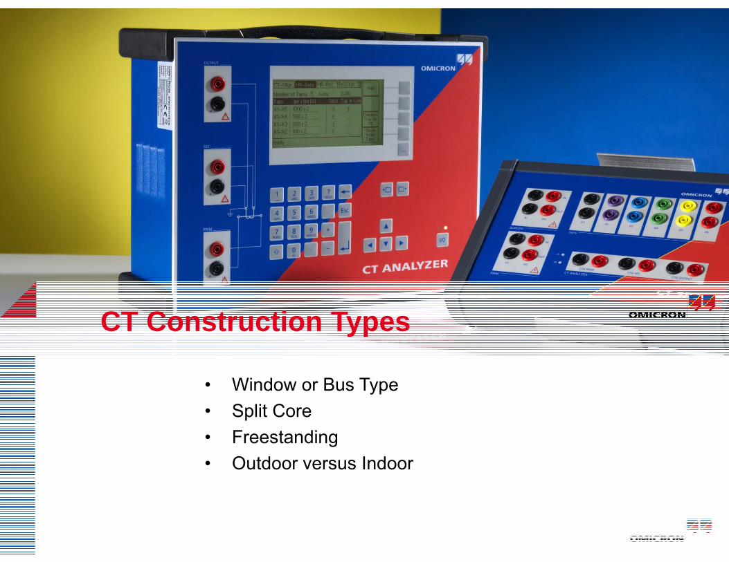
CT Construction Types
• Window or Bus Type• Split Core• Freestanding• Outdoor versus Indoor
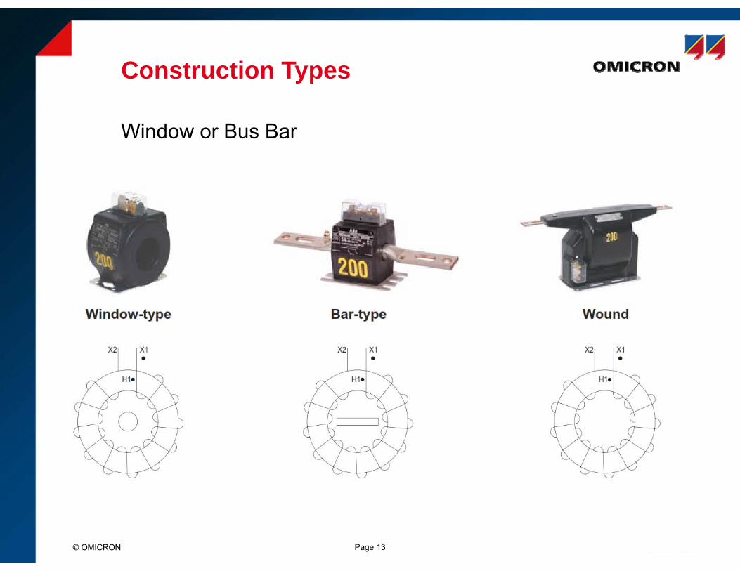
Construction Types
© OMICRON Page 13
Window or Bus Bar
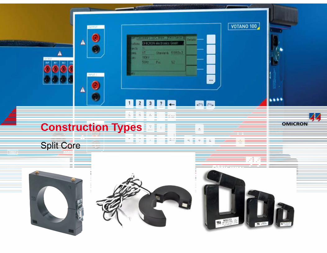
Construction TypesSplit Core

Construction Types
• Wound or Inductive
• Could be GIS Encapsulated
• HV Outdoor Freestanding Shown
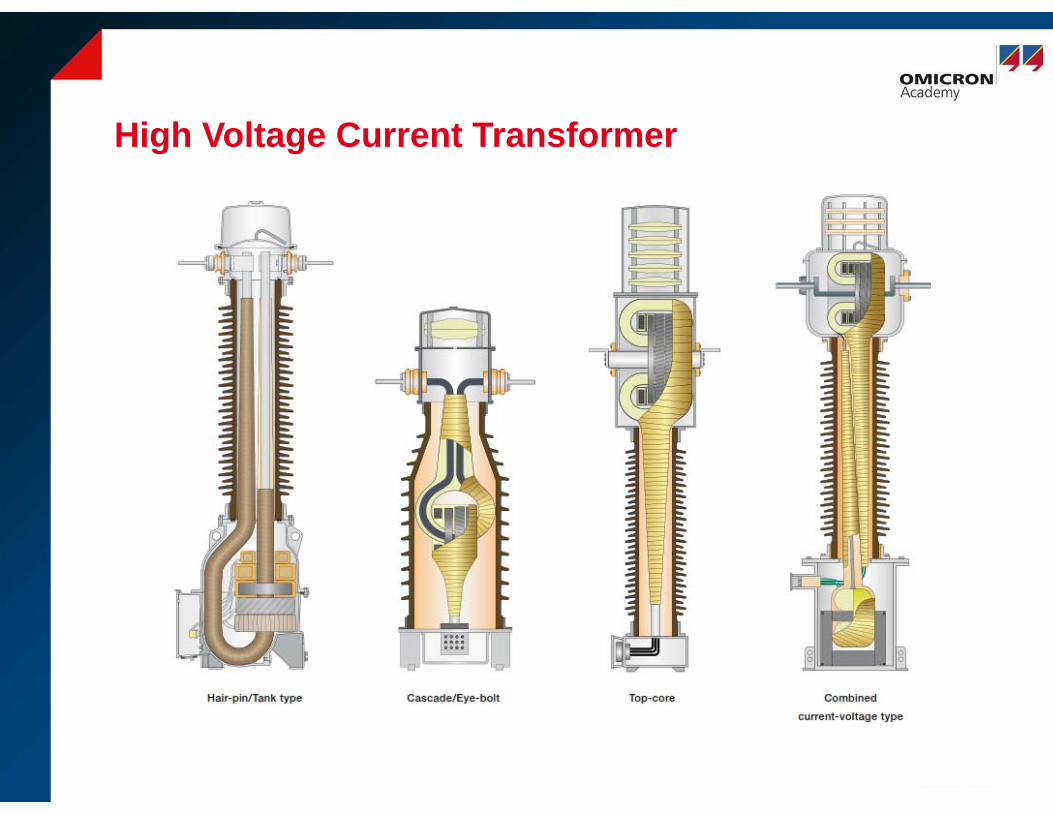
High Voltage Current Transformer
January 19, 2016 Page: 16
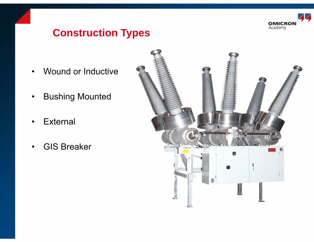
Construction Types
• Wound or Inductive
• Bushing Mounted
• External
• GIS Breaker
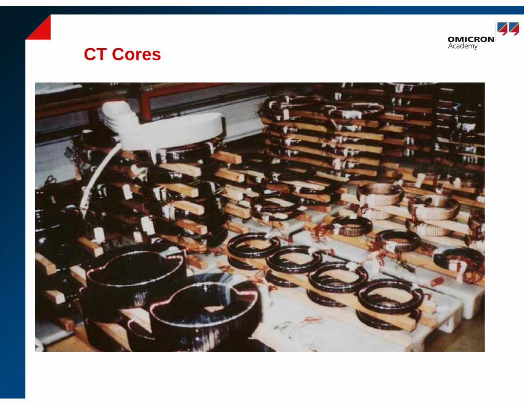
CT Cores
January 19, 2016 Page: 18
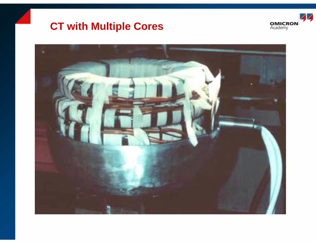
CT with Multiple Cores
January 19, 2016 Page: 20
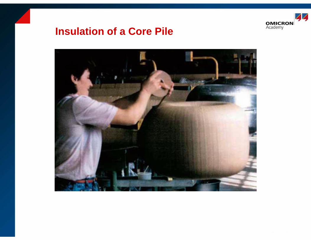
Insulation of a Core Pile
January 19, 2016 Page: 21
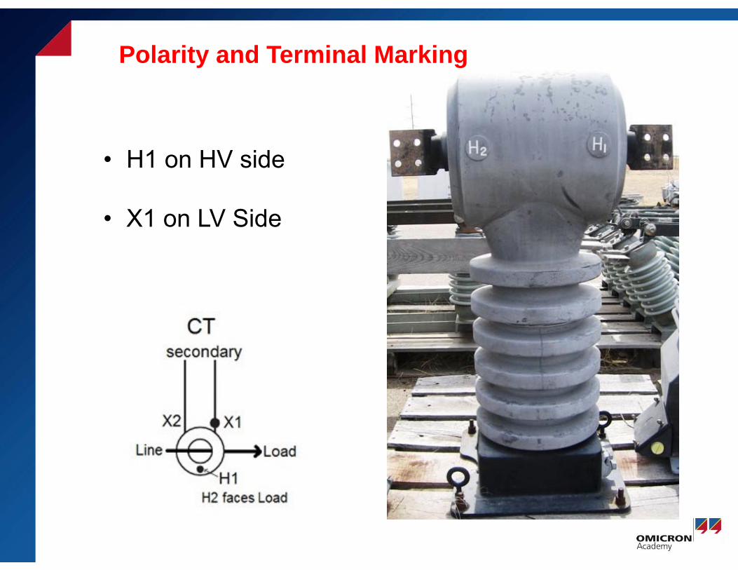
• H1 on HV side
• X1 on LV Side
Polarity and Terminal Marking
January 19, 2016
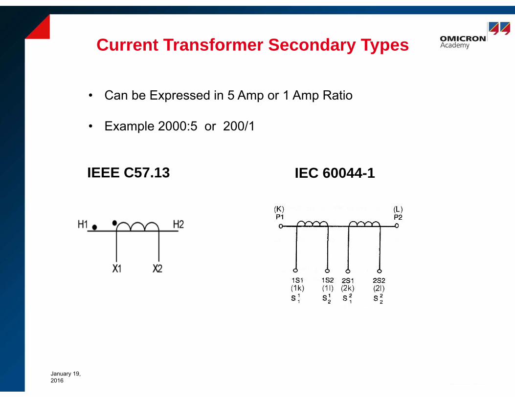
Current Transformer Secondary Types
IEEE C57.13 IEC 60044-1
• Can be Expressed in 5 Amp or 1 Amp Ratio
• Example 2000:5 or 200/1

Page 24© OMICRON
Multi-Ratio ExampleCurrent Transformer Secondary Types

19 January 2016Page 25
CTs for Protection and Metering Applications
• A distinction has to be made between a metering class and a protection class current transformer.
• The designs of the magnetic cores are different.
• This insures that they perform according to the needs of theparticular connected device.

Metering vs Protection Classes
January 19, 2016 Page: 26
Metering core
A metering core is designed to work more accurately within the ratedcurrent range designated. When current flow exceeds that rating, themetering core will become saturated, thereby limiting the amount ofcurrent level within the device. This protects connected meteringdevices from overloading in the presence of fault level current flows. Itbuffers the meter from experiencing excessive torques that might becreated during those faults.
High accuracy in a smaller range.
Less core material is needed
Leads to Lower Saturation Voltages
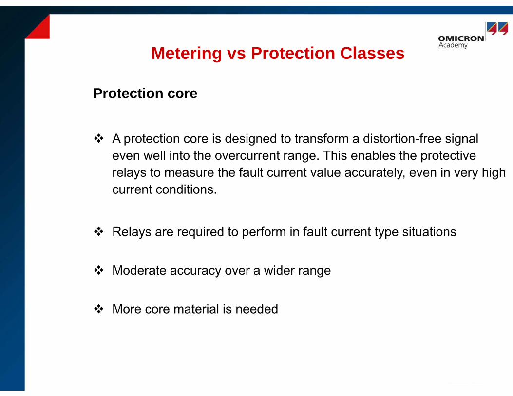
Protection core
A protection core is designed to transform a distortion-free signaleven well into the overcurrent range. This enables the protectiverelays to measure the fault current value accurately, even in very high current conditions.
Relays are required to perform in fault current type situations
Moderate accuracy over a wider range
More core material is needed
Metering vs Protection Classes
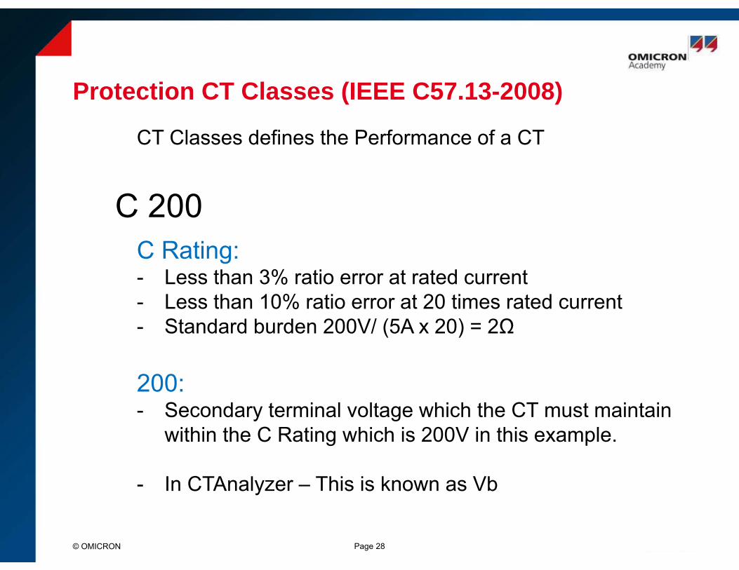
Protection CT Classes (IEEE C57.13-2008)
C 200C Rating: - Less than 3% ratio error at rated current- Less than 10% ratio error at 20 times rated current- Standard burden 200V/ (5A x 20) = 2Ω
200: - Secondary terminal voltage which the CT must maintain
within the C Rating which is 200V in this example.
- In CTAnalyzer – This is known as Vb
Page 28© OMICRON
CT Classes defines the Performance of a CT

Actual Transformer Label (Protection Class)
1. Manufacturer’s name or trademark
2. Manufacturer’s type
3. Rated primary and secondary current
4. Continuous thermal current rating factor (RF)
5. Accuracy classes
6. Rated frequency (Hz)
7. Insulation and Basic impulse insulation level (BIL kV)
Page 29© OMICRON
FLEX-CORECURRENT TRANSFORMERRATIO 3000:5A. CAT 781-302MRRF 1.5 ACC CLASS C20050-400 HZ 600V INS CLASS 10kV BIL
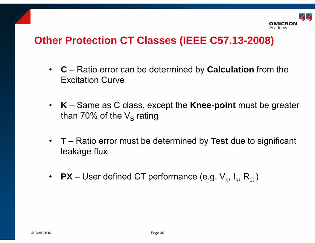
Other Protection CT Classes (IEEE C57.13-2008)
© OMICRON Page 30
• C – Ratio error can be determined by Calculation from the Excitation Curve
• K – Same as C class, except the Knee-point must be greater than 70% of the VB rating
• T – Ratio error must be determined by Test due to significant leakage flux
• PX – User defined CT performance (e.g. Vk, Ik, Rct )

Metering CT Classes (IEEE C57.13-2008)
© OMICRON Page 31
0.3 0.9B
• At 100% rated current, the error limit is 0.3%
• At 10% rated current, the error limit is 0.6% (doubled)
Metering Class CT
Maximum Burden (e.g. 0.9Ω )
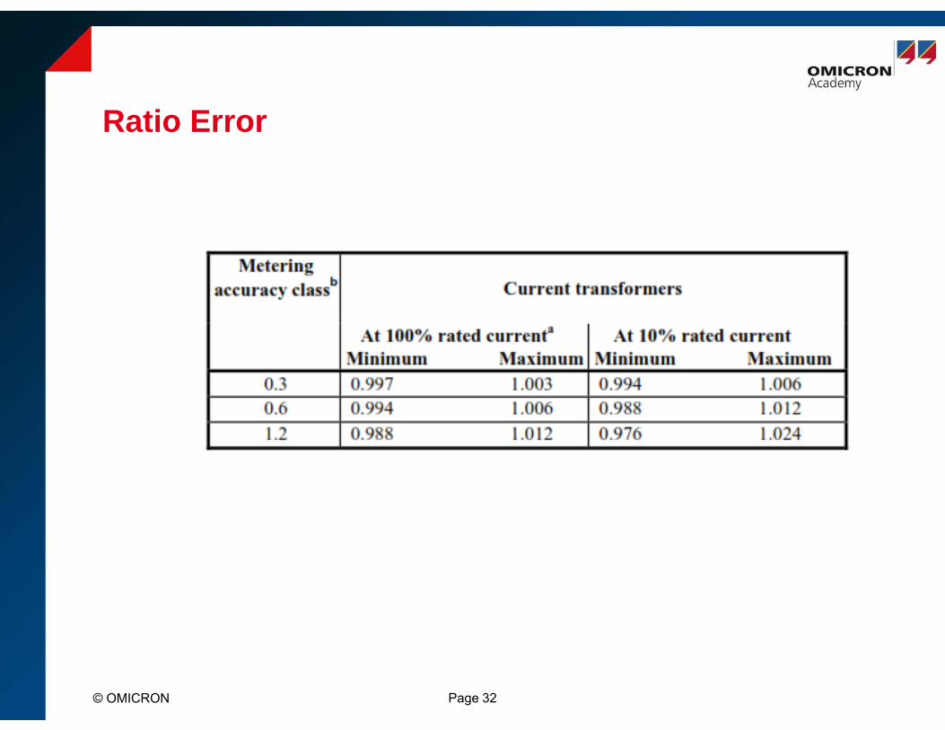
Ratio Error
© OMICRON Page 32
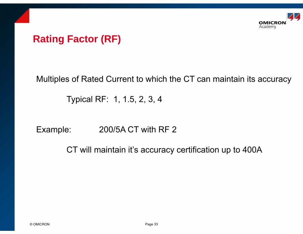
Rating Factor (RF)
© OMICRON Page 33
Multiples of Rated Current to which the CT can maintain its accuracy
Typical RF: 1, 1.5, 2, 3, 4
Example: 200/5A CT with RF 2
CT will maintain it’s accuracy certification up to 400A
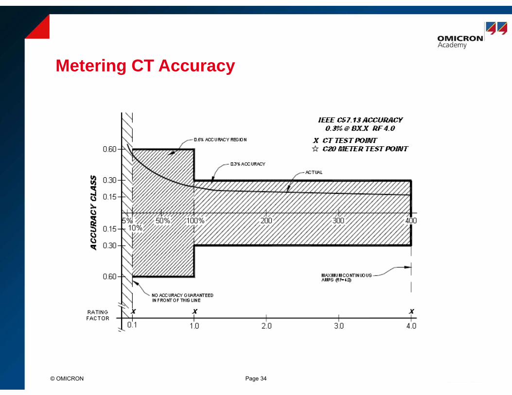
Metering CT Accuracy
© OMICRON Page 34

Actual Transformer Label (Metering)
© OMICRON Page 35
INSTRUMENT TRANSFOMERS,INC.CURRENT TRANSFORMERRATIO 400:5 A. CAT 115-401RF 2.0 ACC CLASS 0.3B0.9 C5050-400 HZ 600V INS CLASS 10kV BIL
1. Manufacturer’s name or trademark
2. Manufacturer’s type
3. Rated primary and secondary current
4. Continuous thermal current rating factor (RF)
5. Accuracy classes
6. Rated frequency (Hz)
7. Insulation and Basic impulse insulation level (BIL kV)
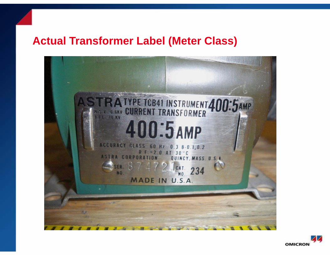
Actual Transformer Label (Meter Class)

Error Parallelogram: Metering CTs
© OMICRON Page 37
Source: IEEE C57.13-2008
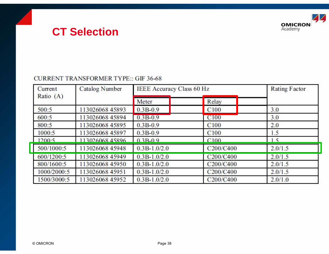
CT Selection
© OMICRON Page 38
Residual Magnetism (Remanence flux)
• When excitation is removed from the CT, some of the magnetic domains retain a degree of orientation relative to the magnetic field that was applied to the core
• Residual magnetism in CTs can be described by amount of flux left in the core
Page 39© OMICRON

Causes of Residual Magnetism
Residual Magnetism Can Occur Due To:
• High Transient Fault Currents
• Circuit Breaker Arc During Trip Operations
• DC Currents Due to Winding Resistance Measurement
• Other Tests
Page 40© OMICRON
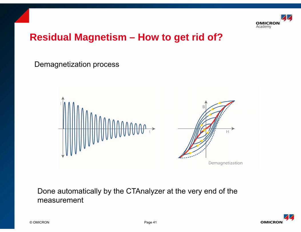
Residual Magnetism – How to get rid of?
Page 41© OMICRON
Demagnetization process
Done automatically by the CTAnalyzer at the very end of the measurement
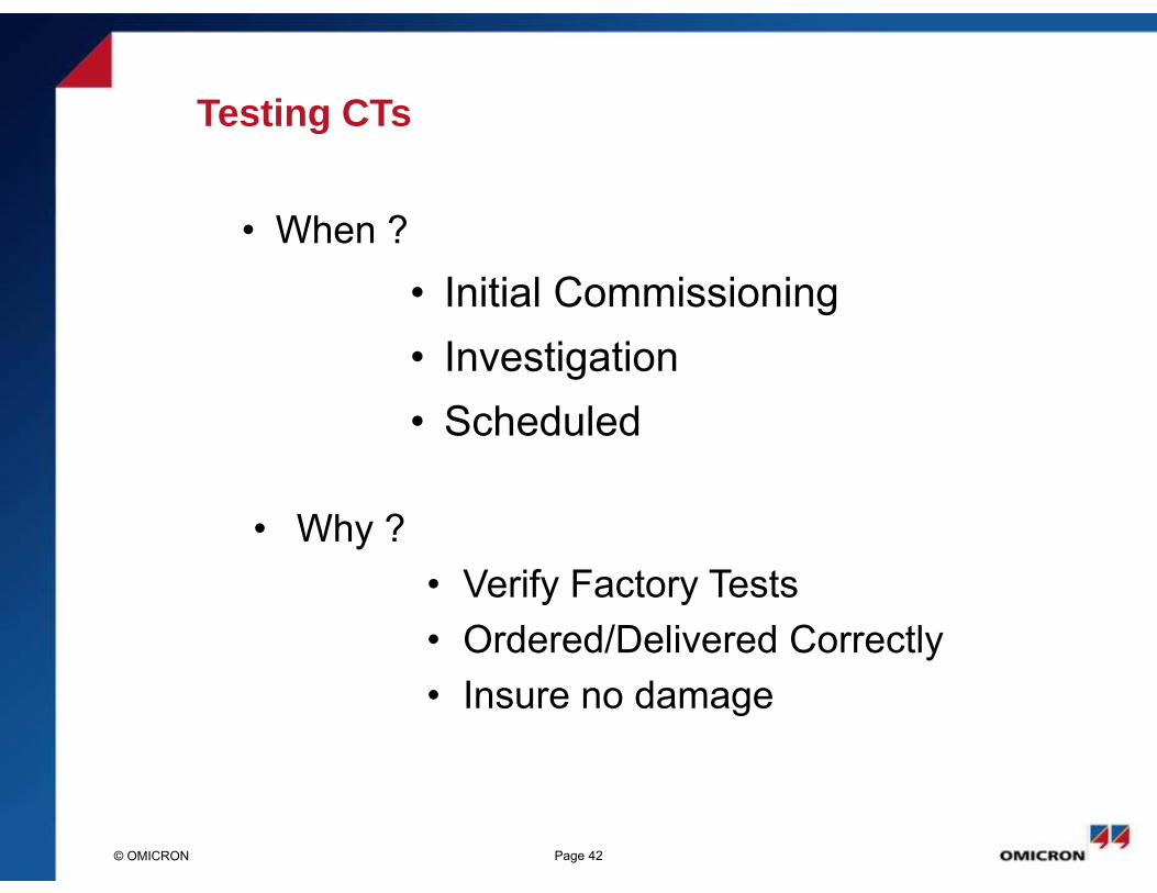
Testing CTs
• When ?• Initial Commissioning• Investigation• Scheduled
Page 42© OMICRON
• Why ?• Verify Factory Tests• Ordered/Delivered Correctly• Insure no damage
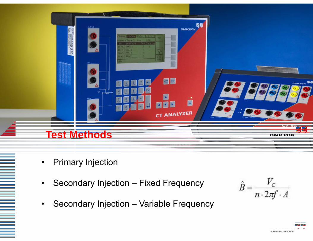
Test Methods
• Primary Injection
• Secondary Injection – Fixed Frequency
• Secondary Injection – Variable Frequency

Test Requirements
• Excitation to Determine Knee/Saturation Point
• Insulation
• Polarity
• Winding Resistance
• Primary Ratio
• Secondary Ratio
• Burden Check
• Documentation

Why So Many Tests?
© OMICRON Page 45
• Ensure proper Relay Operation
• Certify Billing Accuracy
• Reduce Possibility of Failure when Energized
• Reduce Possibility of Injury Due to Failure
• Manufacturing Defects Do Happen
• Installation Errors Do Happen
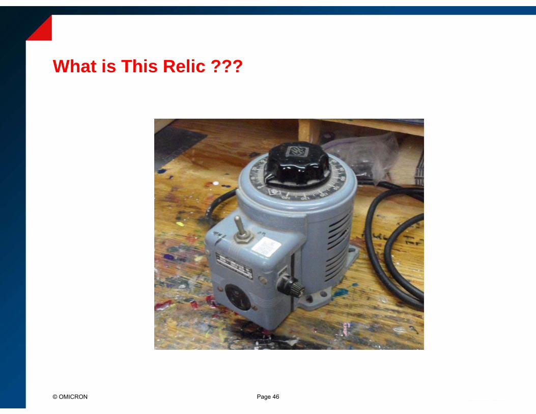
What is This Relic ???
Page 46© OMICRON

Test Setup
Page 47© OMICRON
Test Set or Variac or DC
SourceV V
A

Excitation curves for multi-ratio C class CT
Page 48© OMICRON
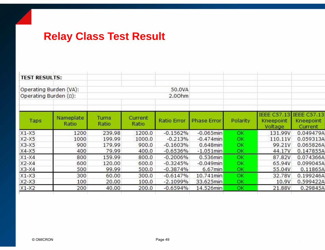
Relay Class Test Result
Page 49© OMICRON

Page 50© OMICRON
Relay Class Test Result
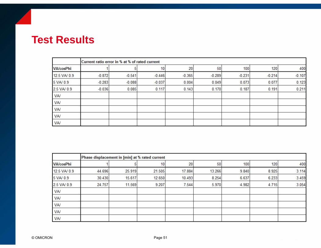
Test Results
Page 51© OMICRON
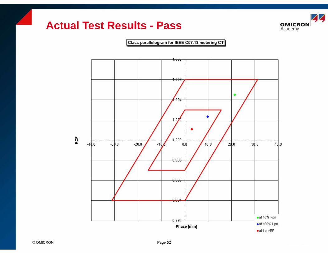
Actual Test Results - Pass
© OMICRON Page 52

Actual Test Results - Failure
© OMICRON Page 53