
Shanghai Huaming Power Equipment Co.,Ltd.
CV2 Type Vacuum On-Load Tap ChangerOperation Instructions
HM 0.460.4101-03-02/2017
2
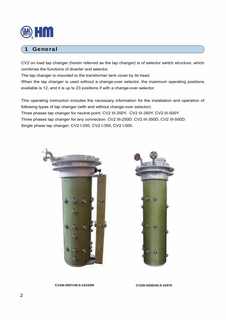
CV2 on load tap changer (herein referred as the tap changer) is of selector switch structure, which
combines the functions of diverter and selector.
The tap changer is mounted to the transformer tank cover by its head.
When the tap changer is used without a change-over selector, the maximum operating positions
available is 12, and it is up to 23 positions if with a change-over selector.
This operating instruction includes the necessary information for the installation and operation of
following types of tap changer (with and without change-over selector).
Three phases tap changer for neutral point: CV2 III-250Y, CV2 III-350Y, CV2 III-500Y.
Three phases tap changer for any connection: CV2 III-250D, CV2 III-350D, CV2 III-500D.
Single phase tap changer: CV2 I-250, CV2 I-350, CV2 I-500.
1 General
CV2III-500Y/40.5-10193W CV2III-500D/40.5-10070
HM 0.460.4101
3
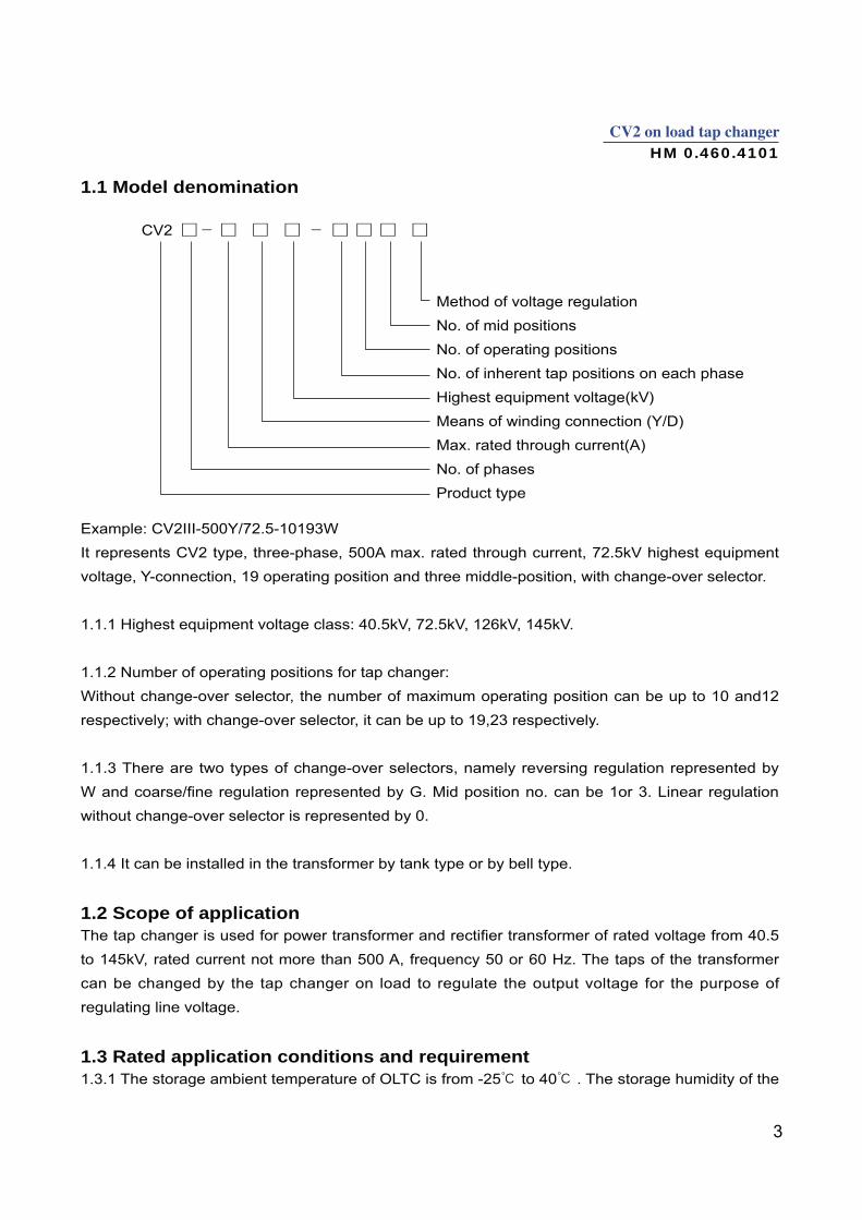
Example: CV2III-500Y/72.5-10193W
It represents CV2 type, three-phase, 500A max. rated through current, 72.5kV highest equipment
voltage, Y-connection, 19 operating position and three middle-position, with change-over selector.
1.1.1 Highest equipment voltage class: 40.5kV, 72.5kV, 126kV, 145kV.
1.1.2 Number of operating positions for tap changer:
Without change-over selector, the number of maximum operating position can be up to 10 and12
respectively; with change-over selector, it can be up to 19,23 respectively.
1.1.3 There are two types of change-over selectors, namely reversing regulation represented by
without change-over selector is represented by 0.
1.1.4 It can be installed in the transformer by tank type or by bell type.
1.2 Scope of application
to 145kV, rated current not more than 500 A, frequency 50 or 60 Hz. The taps of the transformer
can be changed by the tap changer on load to regulate the output voltage for the purpose of
regulating line voltage.
1.3 Rated application conditions and requirement to 40 . The storage humidity of the
No. of mid positions
No. of operating positions
No. of inherent tap positions on each phase
Highest equipment voltage(kV)
No. of phases
Product type
CV2
1.1 Model denomination
4
OLTC should be no more than 85 percent.The service temperature of standard designed OLTC is -25℃ to 40℃
If the temperature exceeds the range of above (-25℃ to 40℃ ), please specify when ordering.Service temperature range of tap changer in oil is -25℃ ~ + 105℃ (suitable for 115℃ during overload).1.3.2 To meet the ordering requirements and comply with the operating environment, if the requested service temperature is out of the range of -25℃ to 40℃
1.3.3 When installing the tap changer on the transformer the perpendicularity with the ground level must not be bigger than 2%.1.3.4 Any serious dust, explosive or corrosive gases must not be present at the installation site of the OLTC.
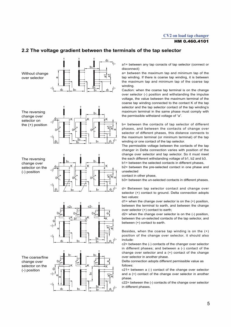
2. Technical Data2.1 Rated parameters of tap changers (see table)
Max. rated through current(A) 250 350 500No. of phases 1 3 3 1 3 3 1 3 3
Connection method - Y D - Y D - Y DMax. rated step
voltage 10 &12 contacts 2000 2000~1500* 1500~1000*
Rated step capacity (kVA) 10 &12 contacts 500 525 525
Short-circuitcurrent test (kA)
Thermal (3s) 4.5 4.5 7.5
Dynamic (Peak) 11.25 11.25 18.75
Max. operating positions12 for linear 12 for linear 10 for linear
23 for reversing or 23 for reversing or 19 for reversing or
Insulationto ground
(kV)
Highest voltage for equipment Um 40.5 72.5 126 145 85 140 230 275 225 325 550 650
Rated separate source ACwithstand voltage(kV/50Hz,1min)
Rated lightning impulsewithstand voltage (kV,1.2/50μs)
Internal Insulation Level Refer to item 2.3
Mechanical Life 1,500,000 operations
Electrical Life 600,000 operations
Oilcompartment
Service pressure 0.03MPaLeakage test No leakage under 0.08 MPa for 24 hours
Over pressure protection Rupture disc bursts at 300±20% KPaProtective relay
Equipped with motor drive unit SHM-D or CMA7Tap changer model CV2 III -250 CV2 I -250 CV2 III-350 CV2 I-350 CV2 III-500 CV2 I-500
Net weight (kg) without oil 120 90 140 100 160 1403) 170 130 185 140 200 180
* Please refer to Fig.5 on page 6
, the suitable material and accessories of the OLTC will be specially selected and applied.
6
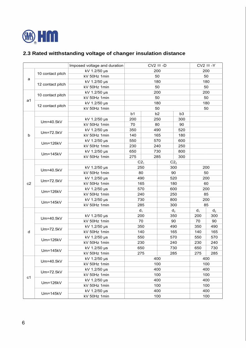
2.3 Rated witthstanding voltage of changer insulation distance
Imposed voltage and duration CV2 -D CV2 -Y
a
10 contact pitchkV 1.2/50 μs 200 200
kV 50Hz 1min 50 50
12 contact pitchkV 1.2/50 μs 180 180
kV 50Hz 1min 50 50
a1
10 contact pitchkV 1.2/50 μs 200 200
kV 50Hz 1min 50 50
12 contact pitchkV 1.2/50 μs 180 180
kV 50Hz 1min 50 50
b
b1 b2 b3
Um=40.5kVkV 1.2/50 μs 200 250 300
kV 50Hz 1min 70 80 90
Um=72.5kVkV 1.2/50 μs 350 490 520
kV 50Hz 1min 140 165 180
Um=126kVkV 1.2/50 μs 550 570 600
kV 50Hz 1min 230 240 250
Um=145kVkV 1.2/50 μs 650 730 800
kV 50Hz 1min 275 285 300
c2
C21 C22
Um=40.5kVkV 1.2/50 μs 250 300 200
kV 50Hz 1min 80 90 50
Um=72.5kVkV 1.2/50 μs 490 520 200
kV 50Hz 1min 165 180 60
Um=126kVkV 1.2/50 μs 570 600 200
kV 50Hz 1min 240 250 85
Um=145kVkV 1.2/50 μs 730 800 200
kV 50Hz 1min 285 300 85
d
d1 d2 d1 d2
Um=40.5kVkV 1.2/50 μs 200 350 200 300
kV 50Hz 1min 70 90 70 90
Um=72.5kVkV 1.2/50 μs 350 490 350 490
kV 50Hz 1min 140 165 140 165
Um=126kVkV 1.2/50 μs 550 570 550 570
kV 50Hz 1min 230 240 230 240
Um=145kVkV 1.2/50 μs 650 730 650 730
kV 50Hz 1min 275 285 275 285
c1
Um=40.5kVkV 1.2/50 μs 400 400
kV 50Hz 1min 100 100
Um=72.5kVkV 1.2/50 μs 400 400
kV 50Hz 1min 100 100
Um=126kVkV 1.2/50 μs 400 400
kV 50Hz 1min 100 100
Um=145kVkV 1.2/50 μs 400 400
kV 50Hz 1min 100 100
8
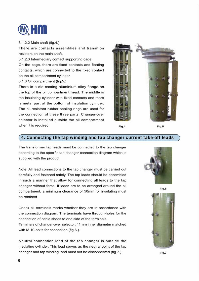
There are contacts assemblies and transition
resistors on the main shaft.
3.1.2.3 Intermediary contact supporting cage
On the cage, there are fixed contacts and floating
contacts, which are connected to the fixed contact
on the oil compartment cylinder.
There is a die casting aluminium alloy flange on
the top of the oil compartment head. The middle is
is metal part at the bottom of insulation cylinder.
The oil-resistant rubber sealing rings are used for
the connection of these three parts. Changer-over
selector is installed outside the oil compartment
when it is required.
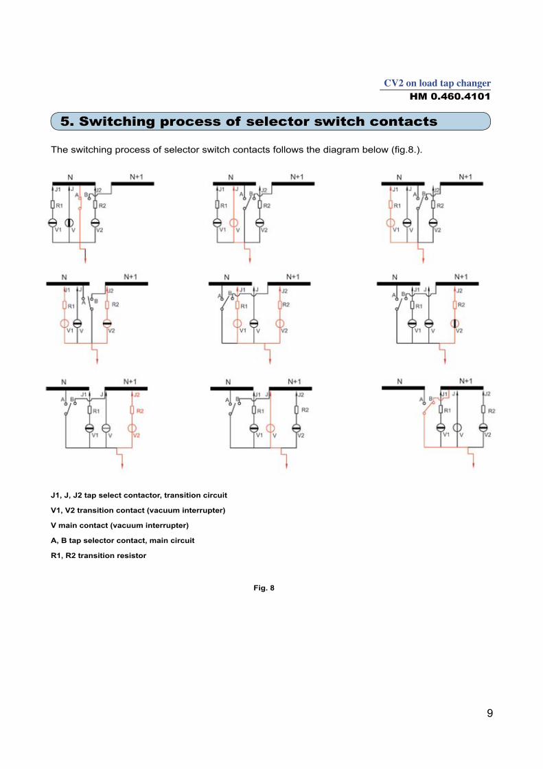
Fig.6
Fig.7
Fig.4 Fig.5
4. Connecting the tap winding and tap changer current take-off leads
The transformer tap leads must be connected to the tap changer
supplied with the product.
Note: All lead connections to the tap changer must be carried out
carefully and fastened safely. The tap leads should be assembled
in such a manner that allow for connecting all leads to the tap
changer without force. If leads are to be arranged around the oil
compartment, a minimum clearance of 50mm for insulating must
be retained.
Check all terminals marks whether they are in accordance with
the connection diagram. The terminals have through-holes for the
connection of cable shoes to one side of the terminals.
Terminals of changer-over selector: 11mm inner diameter matched
Neutral connection lead of the tap changer is outside the
insulating cylinder. This lead serves as the neutral point of the tap
10
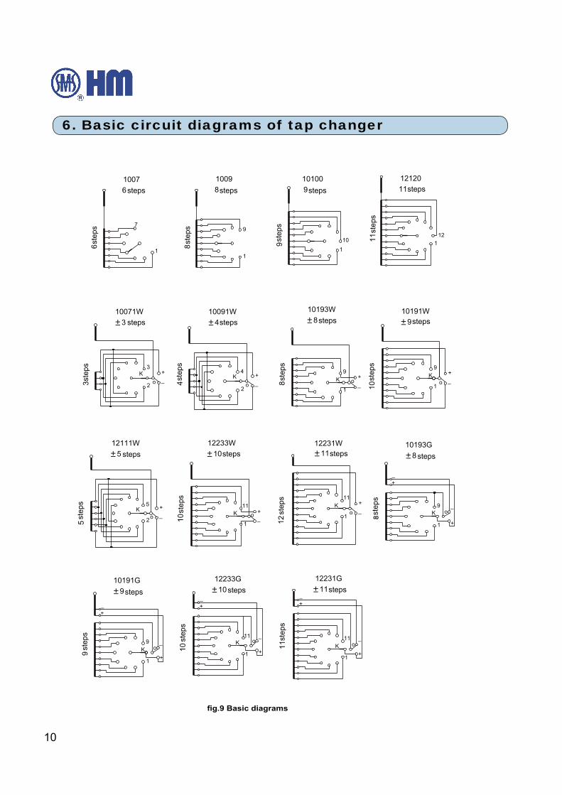
6. Basic circuit diagrams of tap changer
steps steps steps steps
steps steps steps steps
steps
steps
step
s
step
s
step
sst
eps
step
s
step
s
step
s
step
s
step
s
step
s
step
s
step
s
step
s
step
s
step
s
stepssteps
steps steps steps
11
HM 0.460.4101
7. Installation of the tap changer
appendix 2).
7.2 Installation of the tap changer head to the tank top type transformer
Attention: It is used for the installation of tap changer without reversing change over selector to the
tank top type transformer cover only.
Procedures are as following:
1) Clean all sealing surfaces (tap changer head flange and mounting flange). Put an oil-proof
careful not to damage the tap changer terminals.
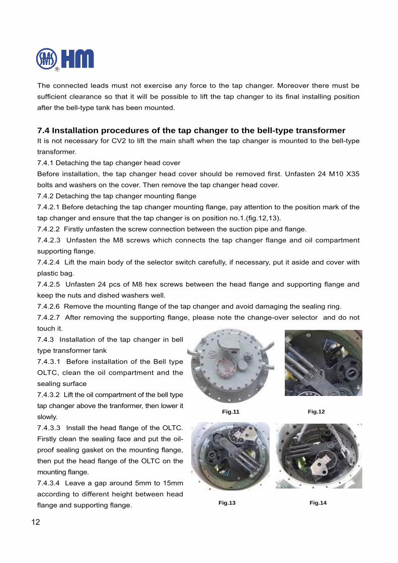
3) Check the position of the completed tap changer.
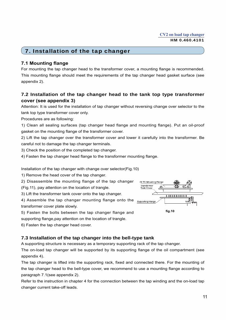
Installation of the tap changer with change over selector(Fig.10)
1) Remove the head cover of the tap changer.
2) Disassemble the mounting flange of the tap changer
(Fig.11), pay attention on the location of trangle.
4) Assemble the tap changer mounting flange onto the
transformer cover plate slowly.
5) Fasten the bolts between the tap changer flange and
6) Fasten the tap changer head cover.
7.3 Installation of the tap changer into the bell-type tankA supporting structure is necessary as a temporary supporting rack of the tap changer.
The on-load tap changer will be supported by its supporting flange of the oil compartment (see
appendix 4).
paragraph 7.1(see appendix 2).
Refer to the instruction in chapter 4 for the connection between the tap winding and the on-load tap
changer current take-off leads.
12
The connected leads must not exercise any force to the tap changer. Moreover there must be
after the bell-type tank has been mounted.
7.4 Installation procedures of the tap changer to the bell-type transformerIt is not necessary for CV2 to lift the main shaft when the tap changer is mounted to the bell-type
transformer.
7.4.1 Detaching the tap changer head cover
Before installation, the tap changer head cover should be removed first. Unfasten 24 M10 X35
bolts and washers on the cover. Then remove the tap changer head cover.
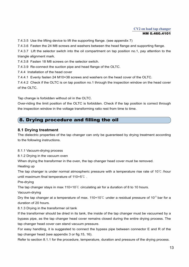
7.4.2.3 Unfasten the M8 screws which connects the tap changer flange and oil compartment
plastic bag.
keep the nuts and dished washers well.
touch it.
7.4.3 Installation of the tap changer in bell
type transformer tank
7.4.3.1 Before installation of the Bell type
sealing surface
tap changer above the tranformer, then lower it
slowly.
Firstly clean the sealing face and put the oil-
proof sealing gasket on the mounting flange,
according to different height between head
Fig.11
Fig.13
Fig.12
Fig.14
14
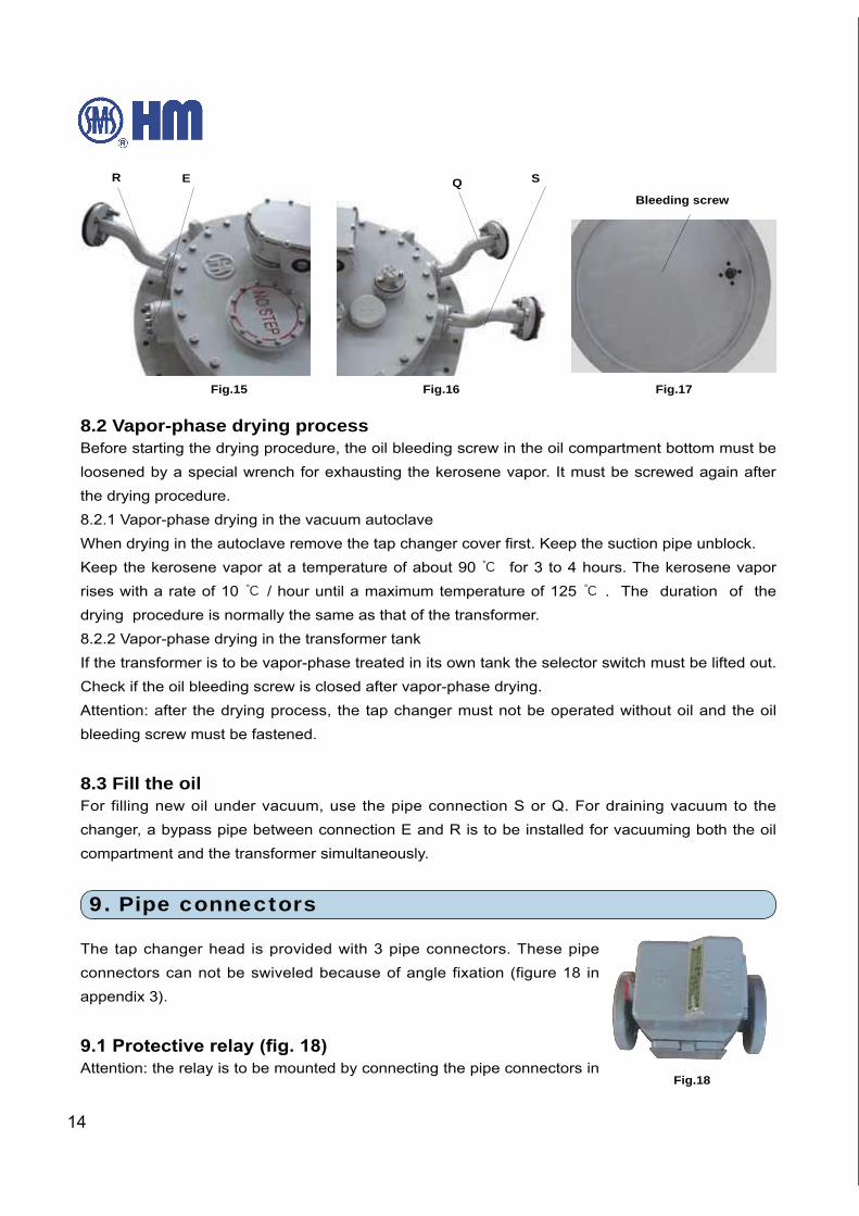
8.2 Vapor-phase drying processBefore starting the drying procedure, the oil bleeding screw in the oil compartment bottom must be
loosened by a special wrench for exhausting the kerosene vapor. It must be screwed again after
the drying procedure.
8.2.1 Vapor-phase drying in the vacuum autoclave
Keep the kerosene vapor at a temperature of about 90 for 3 to 4 hours. The kerosene vapor
rises with a rate of 10 / hour until a maximum temperature of 125 . The duration of the
drying procedure is normally the same as that of the transformer.
8.2.2 Vapor-phase drying in the transformer tank
If the transformer is to be vapor-phase treated in its own tank the selector switch must be lifted out.
Check if the oil bleeding screw is closed after vapor-phase drying.
Attention: after the drying process, the tap changer must not be operated without oil and the oil
bleeding screw must be fastened.
8.3 Fill the oilFor filling new oil under vacuum, use the pipe connection S or Q. For draining vacuum to the
changer, a bypass pipe between connection E and R is to be installed for vacuuming both the oil
compartment and the transformer simultaneously.
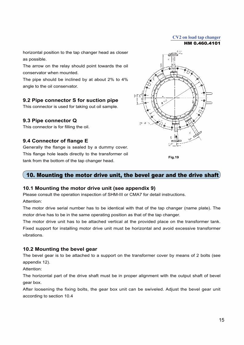
9. Pipe connectors
The tap changer head is provided with 3 pipe connectors. These pipe
connectors can not be swiveled because of angle fixation (figure 18 in
appendix 3).
Attention: the relay is to be mounted by connecting the pipe connectors in
Fig.17
Bleeding screw
Fig.18
Fig.15
R E Q S
Fig.16
16
10.3. After adjusting the upper gear unit the bolts has to be re-tightened.
10.4 Mounting the drive shaftMounting procedure of the drive shaft is as follows: Firstly, the vertical shaft is to be mounted
between motor drive unit and bevel gear, then the horizontal shaft between bevel gear and tap
changer head. The drive shaft couplings are the same for both parts. Both ends of the square shaft
are connected to the respective trunnion by 2 coupling brackets and 1 coupling bolt.
The drive shaft (square shaft), the coupling brackets, bolts, nuts and lock tabs are made of
corrosion proof stainless steel.
The square shaft is delivered 2 meter long, and the square shaft should be cut to the actual
required length before mounting.
according to Operating Instructions. (rotation difference balance check)
11. Putting the tap changer into operation in the transformer factory
11.1 Operational testsBefore applying voltage to the transformer, the mechanical operation of tap changer and motor
drive have to be checked. For these test operations, the tap changer has to be run total 10 full
cycles of operations.
Check that in both limit positions the motor drive stop automatically and the electrical and
mechanical limits function properly.
11.2 Oil replenishment
of oil level of tap changer oil conservator should nearly equal to transformer oil conservator or 100
to 200mm lower.
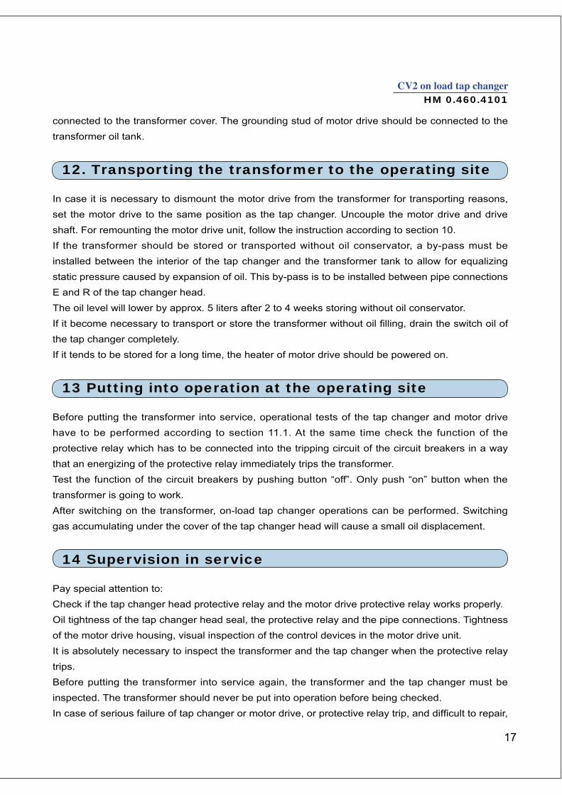
head cover and M30 screw nut, use a spanner to lift valve
11.3.3 Open the valve of protective relay until oil
11.4 GroundingThe grounding stud of tap changer head should be Fig.20
E1
17
HM 0.460.4101
connected to the transformer cover. The grounding stud of motor drive should be connected to the
transformer oil tank.
12. Transporting the transformer to the operating site
In case it is necessary to dismount the motor drive from the transformer for transporting reasons,
set the motor drive to the same position as the tap changer. Uncouple the motor drive and drive
shaft. For remounting the motor drive unit, follow the instruction according to section 10.
If the transformer should be stored or transported without oil conservator, a by-pass must be
installed between the interior of the tap changer and the transformer tank to allow for equalizing
static pressure caused by expansion of oil. This by-pass is to be installed between pipe connections
E and R of the tap changer head.
The oil level will lower by approx. 5 liters after 2 to 4 weeks storing without oil conservator.
the tap changer completely.
If it tends to be stored for a long time, the heater of motor drive should be powered on.
13 Putting into operation at the operating site
Before putting the transformer into service, operational tests of the tap changer and motor drive
have to be performed according to section 11.1. At the same time check the function of the
protective relay which has to be connected into the tripping circuit of the circuit breakers in a way
that an energizing of the protective relay immediately trips the transformer.
Test the function of the circuit breakers by pushing button “off”. Only push “on” button when the
transformer is going to work.
After switching on the transformer, on-load tap changer operations can be performed. Switching
gas accumulating under the cover of the tap changer head will cause a small oil displacement.
14 Supervision in service
Pay special attention to:
Check if the tap changer head protective relay and the motor drive protective relay works properly.
Oil tightness of the tap changer head seal, the protective relay and the pipe connections. Tightness
of the motor drive housing, visual inspection of the control devices in the motor drive unit.
It is absolutely necessary to inspect the transformer and the tap changer when the protective relay
trips.
Before putting the transformer into service again, the transformer and the tap changer must be
inspected. The transformer should never be put into operation before being checked.
18
please contact the Service Department of Shanghai Huaming Power Equipment Co., Ltd.We recommend a periodic inspection of the tap changer equipment to maintain its reliability in operation.The insulation oil of the tap changer should be checked routinely according to relative procedures.
Model S trength of insulation oil Water content of oilY connection 30kV/2.5mm(min) <40μL/LD connection 40kV/2.5mm(min) <30μL/LSingle phase 40kV/2.5mm(min) <30μL/L
15. Inspections
If well organized and prepared, such inspection can be completed by qualified and well trained personnel in one day.The maintenance includes pipe inspection, motor drive check and some replacement of wearing parts.We recommend the inspection work could be done by our Service Department in principle, who can carry it out in a professional and proper manner. Maintenance period:The OLTC insert must be lifted up for inspection when it operates 300,000 times.The whole selector switch must be replaced after 600,000 times operating.
16. Appendix
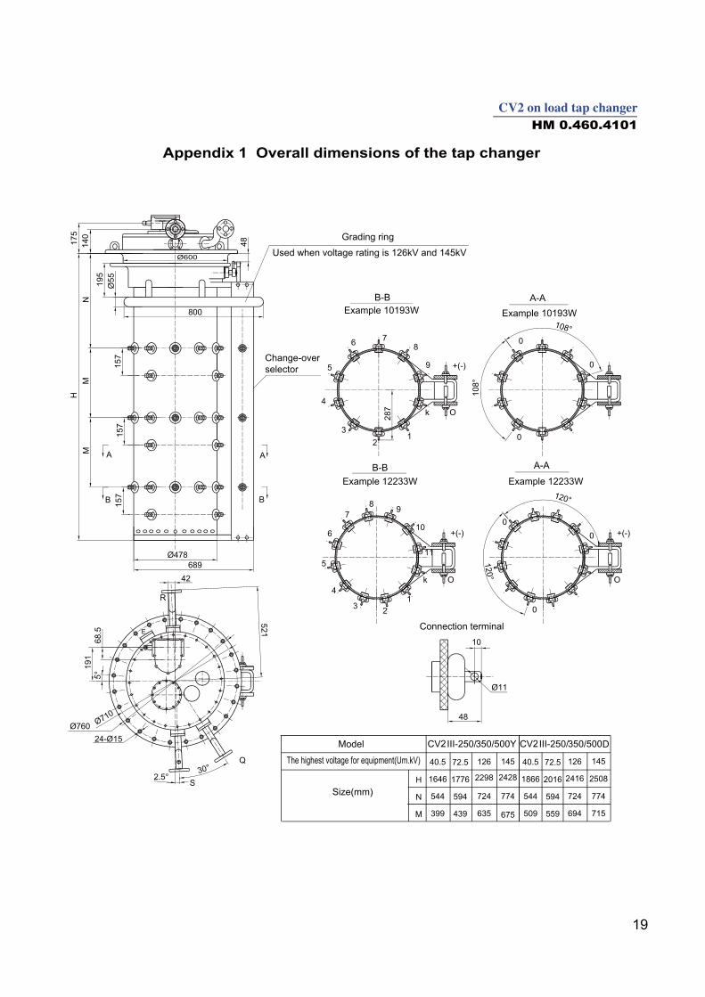
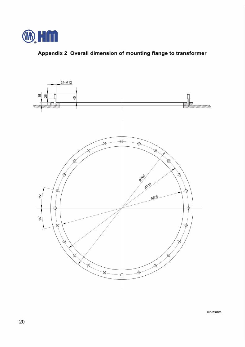
Overall dimensions of the tap changer……………………………………………………………………19……………………………………………………20
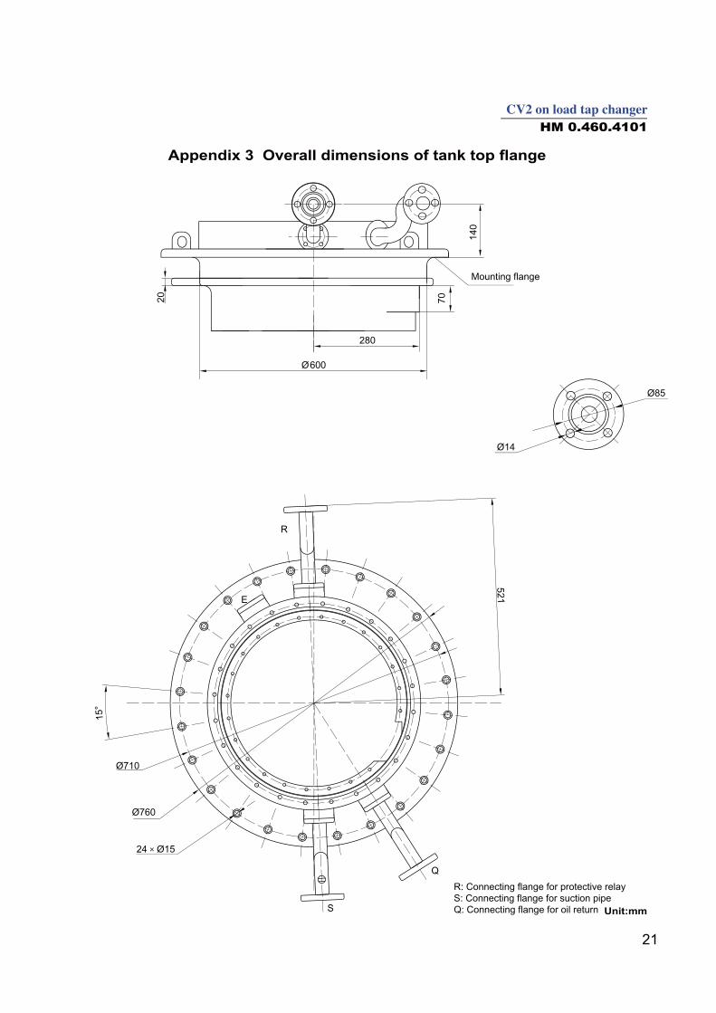
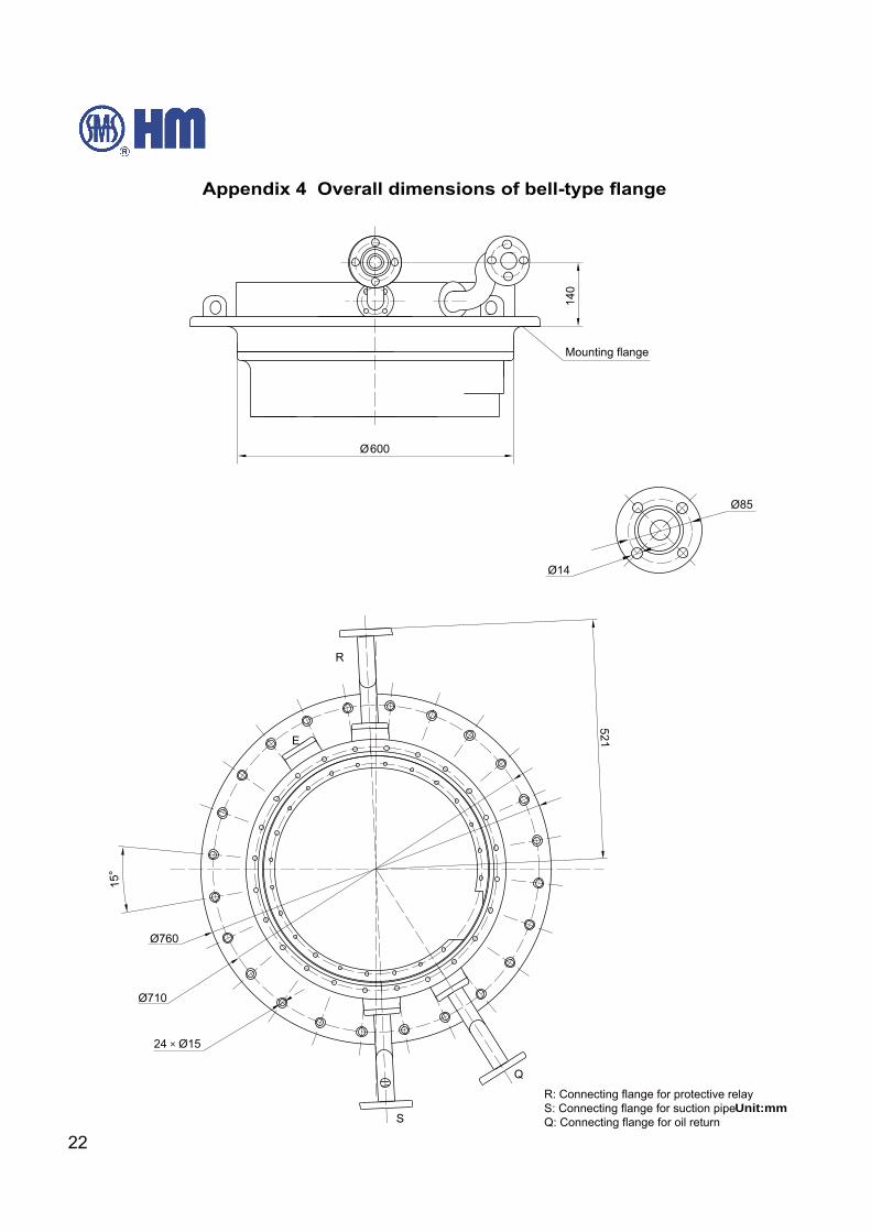
……………………………………………………………………21……………………………………………………………………22
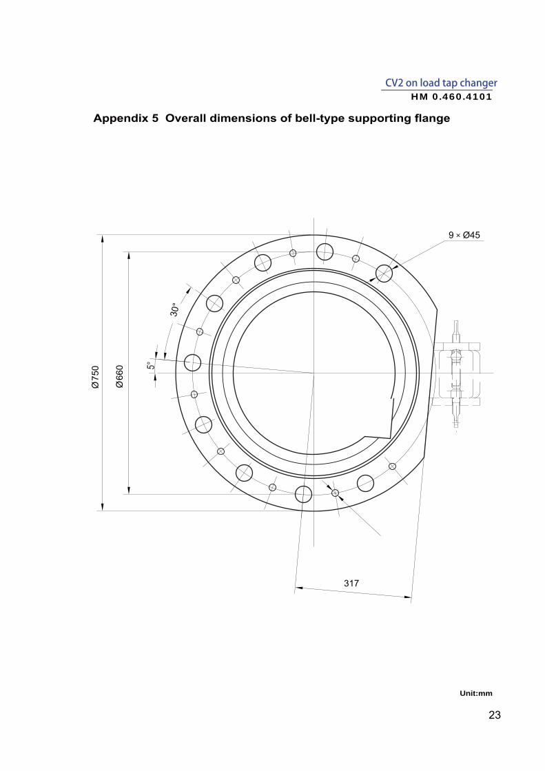
………………………………………………………23Overall dimensions of protective relay……………………………………………………………………24Overall dimensions of SHM-D motor drive unit…………………………………………………………25Connection diagram of SHM-K and SHM-D ……………………………………………………………26Overall dimensions of bevel gear …………………………………………………………………………27
20
ø
ø
ø
Unit:mm
22
R: Connecting flange for protective relayS: Connecting flange for suction pipeQ: Connecting flange for oil return
Mounting flange
Unit:mm
23
CV2 on load tap changerHM 0.460.4101
Unit:mm
5°
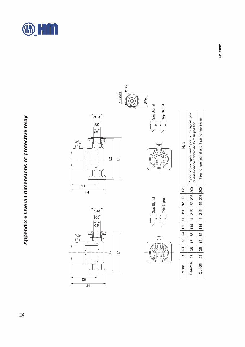
24
Uni
t:m
m
App
endi
x 6
Ove
rall
dim
ensi
ons
of p
rote
ctiv
e re
lay
25
CV2 on load tap changerHM 0.460.4101
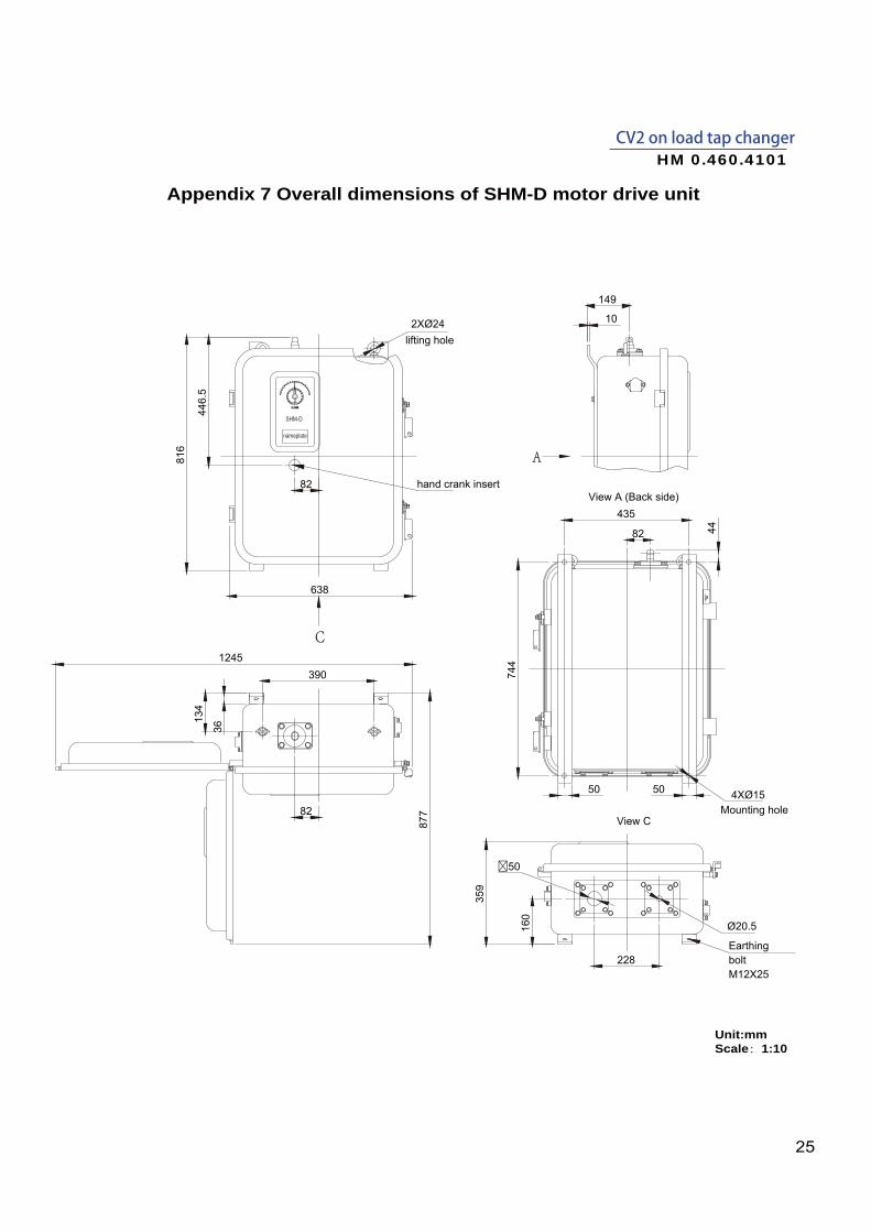
Unit:mmScale:1:10
Appendix 7 Overall dimensions of SHM-D motor drive unit
435
82 44
744
4XØ15
Earthing bolt M12X25
228
160
816
638
149
10
A
C
View A (Back side)
�50
Ø20.5
359
390
View CMounting hole82
2XØ24
134
lifting hole
82
446.
5
hand crank insert
877
1245
50 50
36
SHM-D
nameplate
26
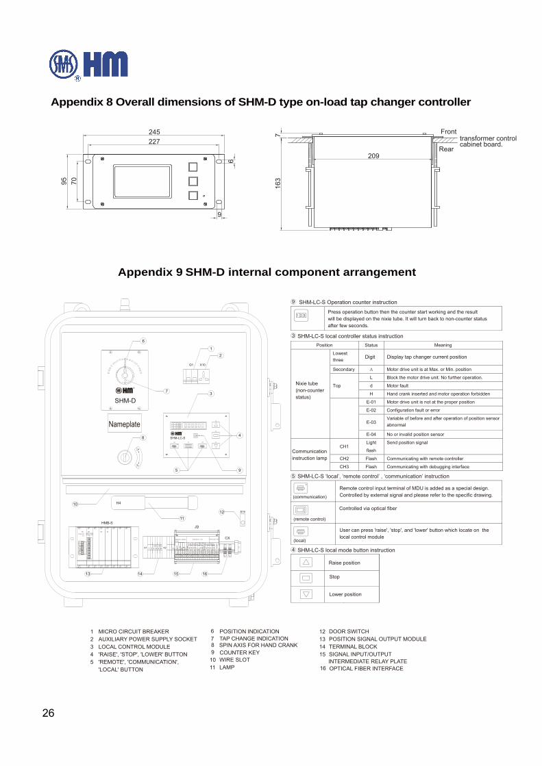
Appendix 8 Overall dimensions of SHM-D type on-load tap changer controller
Appendix 9 SHM-D internal component arrangement
Fronttransformer control cabinet board.
Rear227
7095
6
245
209
716
3
9
⑨ SHM-LC-S Operation counter instruction
③ SHM-LC-S local controller status instruction
⑤ SHM-LC-S ‘local’, ‘remote control’ , ‘communication’ instruction
④ SHM-LC-S local mode button instruction
Press operation button then the counter start working and the result will be displayed on the nixie tube. It will turn back to non-counter statusafter few seconds.
Nixie tube (non-counter status)
Communication instruction lamp
Raise position
Stop
Lower position
User can press 'raise', 'stop', and 'lower' button which locate on the local control module
Controlled via optical fiber
Remote control input terminal of MDU is added as a special design. Controlled by external signal and please refer to the specific drawing.
Display tap changer current positionDigit
1514
12
3
4
5
6
7
8
1613
S19
H4
12
HMB-SJD
CX
1-N
N-1
Q1 X10
SHM-D
BC
D C
OD
E P
OS
ITIO
N
v
I
6.5V
3.3V
GND
L
N
TES
TP
OW
ER
+
-
RS
485
BLO
CK
23
NOCNC
NO
NC
NO
NC
NO
NC
NO
NC
CO
M1
6
CO
M2
N-1
1-N
1 2 3 4 5 7 8 9 10 11 13141516171819 20 2122
CH3CH2CH1
3 2 1
SHM-LC-S
3 2 1X2X1 5 63 421 1-N
N-1
1112
9
10
Nameplate
BINARY-CODED DECIMAL CODE
POWER UNIT
REMOTE C ONTROL
IN PUT
STATUS OUT PUT STATUS OUT PUT
MIN MAX OPERATION
INCOMPLETE
HA
ND
CR
AN
K
RU
NN
INGCAM REMOTE
CONTROL
14
OPTICAL FIBER INTERFACE
AUXILIARY POWER SUPPLY SOCKET 23 LOCAL CONTROL MODULE
'REMOTE', 'COMMUNICATION', 54 'RAISE', 'STOP', 'LOWER' BUTTON 9
POSITION INDICATION76
'LOCAL' BUTTON
TERMINAL BLOCKSIGNAL INPUT/OUTPUT
DOOR SWITCH1213 POSITION SIGNAL OUTPUT MODULE
LAMP1110 WIRE SLOT
16
1 MICRO CIRCUIT BREAKER
15SPIN AXIS FOR HAND CRANKTAP CHANGE INDICATION
COUNTER KEY8
INTERMEDIATE RELAY PLATE
27
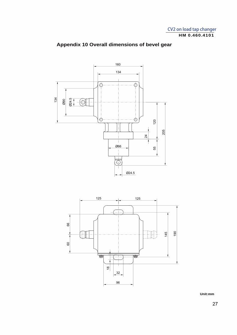
CV2 on load tap changerHM 0.460.4101
Appendix 10 Overall dimensions of bevel gear
Unit:mm

Shanghai Huaming Power Equipment Co., Ltd.Address: No 977 Tong Pu Road, Shanghai 200333, P.R.ChinaTel: +86 21 5270 3965 (direct) +86 21 5270 8966 Ext. 8688 / 8123 / 8698 / 8158 / 8110 / 8658Fax: +86 21 5270 2715Web: www.huaming.com E-mail: [email protected]
April 2017HM reserves the right to change without prior notice


