
CY8CKIT-003
PSoC® 3 FirstTouch™ Starter Kit Guide
Document # 001-49613 Rev. *H
Cypress Semiconductor198 Champion Court
San Jose, CA 95134-1709
Phone (USA): 800.858.1810Phone (Intnl): 408.943.2600
http://www.cypress.com
2 CY8CKIT-003 PSoC 3 FirstTouch Starter Kit Guide, Document # 001-49613 Rev. *H
Copyrights
Copyrights
© Cypress Semiconductor Corporation, 2009-2012. The information contained herein is subject to change without notice.Cypress Semiconductor Corporation assumes no responsibility for the use of any circuitry other than circuitry embodied in aCypress product. Nor does it convey or imply any license under patent or other rights. Cypress products are not warrantednor intended to be used for medical, life support, life saving, critical control or safety applications, unless pursuant to anexpress written agreement with Cypress. Furthermore, Cypress does not authorize its products for use as critical componentsin life-support systems where a malfunction or failure may reasonably be expected to result in significant injury to the user.The inclusion of Cypress products in life-support systems application implies that the manufacturer assumes all risk of suchuse and in doing so indemnifies Cypress against all charges.
Any Source Code (software and/or firmware) is owned by Cypress Semiconductor Corporation (Cypress) and is protected byand subject to worldwide patent protection (United States and foreign), United States copyright laws and international treatyprovisions. Cypress hereby grants to licensee a personal, non-exclusive, non-transferable license to copy, use, modify, createderivative works of, and compile the Cypress Source Code and derivative works for the sole purpose of creating custom soft-ware and or firmware in support of licensee product to be used only in conjunction with a Cypress integrated circuit as speci-fied in the applicable agreement. Any reproduction, modification, translation, compilation, or representation of this SourceCode except as specified above is prohibited without the express written permission of Cypress.
Disclaimer: CYPRESS MAKES NO WARRANTY OF ANY KIND, EXPRESS OR IMPLIED, WITH REGARD TO THIS MATE-RIAL, INCLUDING, BUT NOT LIMITED TO, THE IMPLIED WARRANTIES OF MERCHANTABILITY AND FITNESS FOR APARTICULAR PURPOSE. Cypress reserves the right to make changes without further notice to the materials describedherein. Cypress does not assume any liability arising out of the application or use of any product or circuit described herein.Cypress does not authorize its products for use as critical components in life-support systems where a malfunction or failuremay reasonably be expected to result in significant injury to the user. The inclusion of Cypress’ product in a life-support sys-tems application implies that the manufacturer assumes all risk of such use and in doing so indemnifies Cypress against allcharges.
Use may be limited by and subject to the applicable Cypress software license agreement.
PSoC Designer™, PSoC Creator™, and Programmable System-on-Chip™ are trademarks and PSoC® is a registeredtrademark of Cypress Semiconductor Corp. All other trademarks or registered trademarks referenced herein are property ofthe respective corporations.
Flash Code Protection
Cypress products meet the specifications contained in their particular Cypress PSoC Datasheets. Cypress believes that itsfamily of PSoC products is one of the most secure families of its kind on the market today, regardless of how they are used.There may be methods, unknown to Cypress, that can breach the code protection features. Any of these methods, to ourknowledge, would be dishonest and possibly illegal. Neither Cypress nor any other semiconductor manufacturer can guaran-tee the security of their code. Code protection does not mean that we are guaranteeing the product as "unbreakable."
Cypress is willing to work with the customer who is concerned about the integrity of their code. Code protection is constantlyevolving. We at Cypress are committed to continuously improving the code protection features of our products.
CY8CKIT-003 PSoC 3 FirstTouch Starter Kit Guide, Document # 001-49613 Rev. *H 3
Contents
1. Introduction 5
1.1 Welcome......................................................................................................................51.2 Kit Contents .................................................................................................................51.3 Additional Learning Resources....................................................................................6
1.3.1 Beginner Resources.........................................................................................61.3.2 Engineers Looking for More .............................................................................61.3.3 Learning from Peers.........................................................................................6
1.4 Document Revision History ........................................................................................71.5 Documentation Conventions .......................................................................................7
2. Getting Started 92.1 Hardware .....................................................................................................................9
2.1.1 Protection Circuit............................................................................................102.1.2 ESD Protection on USB Lines........................................................................102.1.3 Battery Specifications.....................................................................................10
3. Installation 113.1 Install Hardware.........................................................................................................11
3.1.1 Hardware Jumpers.........................................................................................113.2 Install Software ..........................................................................................................123.3 Verify Kit Version .......................................................................................................13
4. Code Examples 15
4.1 PSoC Rocks ..............................................................................................................154.1.1 Open the PSoC Rocks Project.......................................................................154.1.2 Modify PSoC Rocks Project ...........................................................................154.1.3 Build, Program, and Run the PSoC Rocks Project ........................................164.1.4 Schematic Design PSoC Creator...................................................................174.1.5 How the PSoC Rocks Project Works .............................................................184.1.6 PCB Schematic ..............................................................................................20
4.2 Bubble Level Emulator...............................................................................................214.2.1 How the Bubble Level Emulator Project Works .............................................224.2.2 PCB Schematic ..............................................................................................23
4.3 ThermistorTemperatureSense...................................................................................244.3.1 How the ThermistorTemperatureSense Project Works ..................................24
4.3.1.1 Temperature Sensing Design Principle ...........................................254.3.2 PCB Schematic ..............................................................................................26
4.4 CapSense Slider........................................................................................................274.4.1 How the CapSense Slider Project Works.......................................................274.4.2 PCB Schematic ..............................................................................................29
4.5 Proximity Sensor........................................................................................................304.5.1 How the Proximity Sensor Project Works ......................................................31

4 CY8CKIT-003 PSoC 3 FirstTouch Starter Kit Guide, Document # 001-49613 Rev. *H
Contents
4.5.2 PCB Schematic..............................................................................................32
5. Technical Reference 33
5.1 PSoC 3 FirstTouch Starter Kit Schematic .................................................................335.1.1 Hardware Jumpers.........................................................................................345.1.2 Board Layout .................................................................................................355.1.3 Bill of Material (BOM) ....................................................................................36
5.2 PSoC 3 Pin Assignment on PSoC 3 FirstTouch Starter Kit Board ............................39

CY8CKIT-003 PSoC 3 FirstTouch Starter Kit Guide, Document # 001-49613 Rev. *H 5
1. Introduction
1.1 Welcome
Thank you for your interest in the CY8CKIT-003 PSoC® 3 FirstTouch™ Starter Kit. This kit isdesigned to introduce you to the PSoC programmable system-on-chip design methodology andCypress's new PSoC 3 architecture. This full-featured starter kit ships with an array of sensors, I/Os,projects, and software to quickly get you up to speed with PSoC Creator™ and our powerful designmethodology so you can easily evaluate PSoC and see what values the solution can provide.
This kit, in addition to the new PSoC 3 architecture, features the following:
■ PSoC Creator development software with an integrated, free-edition Keil C51 Compiler
■ USB-based serial wire debugging (SWD) protocol programmer and debug interface
■ Accelerometer analog sensor
■ Thermistor analog sensor
■ Proximity analog sensor
■ CapSense® analog touch-sensing interface
■ 28-pin general purpose I/O pins
■ 12-pin wireless module header
This guide provides instructions on how to easily evaluate the PSoC 3 architecture and PSoC Cre-ator design methodology through five code examples.
If you have questions about or need help with this kit, visit our online technical support center athttp://www.cypress.com/go/support for support options, or contact your local Cypress salesrepresentative or authorized distributor.
1.2 Kit Contents
PSoC 3 FirstTouch Starter Kit contains:
■ Evaluation board
■ Quick start guide
■ Kit CD/DVD
■ USB A to mini B cable
■ Proximity wire (for use as proximity detection antenna)
■ 9 V battery

6 CY8CKIT-003 PSoC 3 FirstTouch Starter Kit Guide, Document # 001-49613 Rev. *H
Introduction
1.3 Additional Learning Resources
Visit http://www.cypress.com/go/psoc3 for additional learning resources in the form of datasheets,technical reference manual, and application notes.
1.3.1 Beginner Resources
AN54181 - PSoC 3 - Getting Started with a PSoC 3 Design Project
PSoC Creator Training
1.3.2 Engineers Looking for More
AN54460 - PSoC 3 and PSoC 5 Interrupts
AN52705 - PSoC 3 and PSoC 5 - Getting Started with DMA
AN52701 - PSoC 3 - How to Enable CAN Bus Communication
AN54439 - PSoC 3 and PSoC 5 External Crystal Oscillators
AN52927 - PSoC 3: Segment LCD Direct Drive
Cypress continually strives to provide the best support. Click here to view a growing list ofapplication notes for PSoC 3 and PSoC 5.
1.3.3 Learning from Peers
Cypress Developer Community Forums

CY8CKIT-003 PSoC 3 FirstTouch Starter Kit Guide, Document # 001-49613 Rev. *H 7
Introduction
1.4 Document Revision History
1.5 Documentation Conventions
Table 1-1. Revision History
RevisionPDF
Creation Date
Origin of Change
Description of Change
** 02/19/09 KKU/VED New kit user guide.
*A 06/19/09KKU/AESA
Updated Guide to the latest FTK Board Revision
*B 07/28/09 KKU Updated Guide to the latest FTK Board Revision
*C 04/20/11 SASH
Updated PSoC Rocks schematic
Updated to PSoC Programmer 3.12.3
Updated to PSoC Creator 1.0 Production
*D 12/16/11 SASH Updated PSoC Creator release.
*E 01/31/11 RKAD No change. Sunset review
*F 05/03/12 SASH Added the Additional Resources section
*G 07/19/2012 SASH
Added Safety Information chapter on page 5.
Updated Install Software on page 12 (Added a note at the end of the section).
Updated ThermistorTemperatureSense on page 24 (Updated How the ThermistorTemperatureSense Project Works on page 24 (Updated Temperature Sensing Design Principle on page 25)).
Added Regulatory Compliance Information on page 43.
Replaced all instances of CD with CD/DVD across the document.
*H 09/06/2012 SASH
Updated board images.
Added 2.1.1 Protection Circuit and 2.1.2 ESD Protection on USB Lines
Updated 3.3 Verify Kit Version
Table 1-2. Document Conventions for Guides
Convention Usage
Courier NewDisplays file locations, user entered text, and source code:C:\ ...cd\icc\
ItalicsDisplays file names and reference documentation:Read about the sourcefile.hex file in the PSoC Designer User Guide.
[Bracketed, Bold]Displays keyboard commands in procedures:[Enter] or [Ctrl] [C]
File > OpenRepresents menu paths:File > Open > New Project
BoldDisplays commands, menu paths, and icon names in procedures:Click the File icon and then click Open.
Times New RomanDisplays an equation:2 + 2 = 4
Text in gray boxes Describes Cautions or unique functionality of the product.

8 CY8CKIT-003 PSoC 3 FirstTouch Starter Kit Guide, Document # 001-49613 Rev. *H
Introduction
CY8CKIT-003 PSoC 3 FirstTouch Starter Kit Guide, Document # 001-49613 Rev. *H 9
2. Getting Started
2.1 Hardware
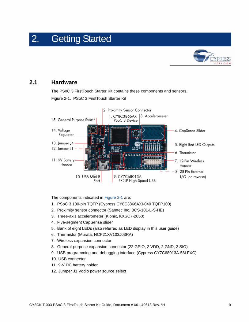
The PSoC 3 FirstTouch Starter Kit contains these components and sensors.
Figure 2-1. PSoC 3 FirstTouch Starter Kit
The components indicated in Figure 2-1 are:
1. PSoC 3 100-pin TQFP (Cypress CY8C3866AXI-040 TQFP100)
2. Proximity sensor connector (Samtec Inc, BCS-101-L-S-HE)
3. Three-axis accelerometer (Kionix, KXSC7-2050)
4. Five-segment CapSense slider
5. Bank of eight LEDs (also referred as LED display in this user guide)
6. Thermistor (Murata, NCP21XV103J03RA)
7. Wireless expansion connector
8. General-purpose expansion connector (22 GPIO, 2 VDD, 2 GND, 2 SIO)
9. USB programming and debugging interface (Cypress CY7C68013A-56LFXC)
10. USB connector
11. 9-V DC battery holder
12. Jumper J1 Vddio power source select
15. General Purpose 1. CY8C3866AXI
2. Proximity Sensor Connector3. Accelerometer
4. CapSense Slider14. Voltage
11. 9V Battery
10. USB Mini B 9. CY7C68013A 8. 28-Pin External
7. 12-Pin Wireless
6. Thermistor
5. Eight Red LED Outputs
Header
FX2LP High Speed USB
PSoC 3 Device
PortI/O (on reverse)
Header
Regulator
Switch
13. Jumper J412. Jumper J1
10 CY8CKIT-003 PSoC 3 FirstTouch Starter Kit Guide, Document # 001-49613 Rev. *H
Getting Started
13. Jumper J4 voltage regulator source select
14. Voltage regulator (Zetex Inc, ZLDO330)
15. General-purpose push button switch
The VDDIO1 and VDDIO3 power domains are always powered by 3.3 V. The VDDIO0 and VDDIO2can range from 1.8 V to 5 V depending on the J1 and J4 jumper settings. See Hardware Jumpers onpage 34 for more details.
Note Wireless modules such as ArtaFlex Radio Modules or Cypress Low-power Radio modulessuch as CYWM6934/35 (not provided with the kit) can be plugged into the Wireless expansion con-nector on the board. You can design your own radio module using the Cypress CyFI low-power chipCYRF7936-40LXI.
2.1.1 Protection Circuit
The protection circuit consists of an 800 mA positive temperature coefficient (PTC) resettable fuseand a 5.6 V/5 W Zener diode for VDDIO pins on header J2 and J3. When an external voltage morethan 5.6 V is applied, the Zener diode enters the break down region and draws large current. Largecurrent passing through the PTC fuse cuts off the power line and resets when power supply is dis-connected as current or temperature of the fuse reduces. When a revere voltage is applied, theZener diode is forward-biased (Vf= 0.7 V) and a closed path is available through the fuse. Hence, alarge current is drawn from the supply leading to a rise in the temperature of fuse. This cuts off thesupply, protecting the PSoC from reverse voltage. Similarly, when a short circuit occurs, the fuseopens or breaks within 2 ms; this is because a large current is drawn through the fuse, whichincreases the temperature of the fuse and protects the regulator. The protection circuit allows two-way power supply at the header allowing you to power externally from 1.8 V to 5.5 V or use theonboard power supply for powering external components with maximum of around 0.324 V seriesdrop at 270 mA current across the PTC fuse as the maximum fuse resistance is 1.2 .
2.1.2 ESD Protection on USB Lines
As a best practice, USB lines are protected from ESD up to ±8 kV contact / ±15 kV air discharge byusing the CD143A-SR05LC integrated chip.
2.1.3 Battery Specifications
Use batteries with the following specifications:
■ Battery size: 9 V (6LR61)
■ Output voltage: 9 VDC
■ Type: Non-rechargeable alkaline consumer batteries
■ RoHS status: RoHS compliant
■ Lead free status: Pb-free
Some recommended part numbers include 6LR61XWA/1SB (Panasonic), MN1604 (Duracell), and6LR61 (Energizer).

CY8CKIT-003 PSoC 3 FirstTouch Starter Kit Guide, Document # 001-49613 Rev. *H 11
3. Installation
3.1 Install Hardware
This section shows you how to use the PSoC 3 FirstTouch Starter Kit.
Note This kit comes with a factory programmed demonstration to display "PSoC Rocks!" messageon the LED display when the board is waved.
1. Unpack the PSoC 3 FirstTouch Starter Kit.
2. Connect a 9-V DC battery to the battery connector on the kit board.
3. Hold the board and battery exposing the LEDs. Then, continuously wave the board from side to side in the plane of the PCB (shown in Figure 3-1).
4. As you wave the board, the rasterized image of the message "PSoC Rocks!" appears, as shown in the following figure.
5. Keep waving. The message changes every few seconds.
Figure 3-1. Rasterized Image of "PSoC Rocks!"
3.1.1 Hardware Jumpers
There are two jumpers for power configuration. All examples are run with the default setup of 3.3 Voperation. This requires J1-2 to connect to J1-3 and J4-2 to connect to J4-3. For all other configura-tions, see section Hardware Jumpers on page 34.

12 CY8CKIT-003 PSoC 3 FirstTouch Starter Kit Guide, Document # 001-49613 Rev. *H
Installation
3.2 Install Software
When installing the PSoC 3 FirstTouch Starter Kit, the installer checks if the prerequisites, PSoCCreator, PSoC Programmer, Windows Installer, Windows.NET, Acrobat Reader, and Keil C51Compiler, are installed in your PC. If these applications are not installed, then the installer promptsyou to install them.
1. Insert the kit CD/DVD into the your PC. The CD/DVD is designed to automatically open an installation dialog (see Figure 3-3). If it does not automatically open, manually open this by running cyautorun.exe on the kit CD/DVD.
Figure 3-2. Auto Run File View
2. The kit CD/DVD installation dialog prompts you to open this file or begin installing the develop-ment environment software. Click the Install PSoC 3 FirstTouch Starter Kit menu item.
Figure 3-3. Installation Dialog.
3. As specified, this installation process first determines if you have all prerequisite software. Follow the on-screen dialogs to complete all required installations. After following these steps, you must have the following software installed:
a. PSoC Creator 1.0 SP1 or later
b. PSoC Programmer 3.12.4 or later
c. Keil C51 Compiler (Cypress edition)

CY8CKIT-003 PSoC 3 FirstTouch Starter Kit Guide, Document # 001-49613 Rev. *H 13
Installation
d. GNU GCC Compiler (for PSoC 5 development)
e. PSoC 3 FirstTouch Starter Kit example projects and documentation
4. Following the software installation, verify if you have all hardware and drivers set up for the PSoC 3 FirstTouch Starter Kit by connecting the kit board to your PC via its USB interface. Because this is the first time you have connected this board to this PC, initial driver installations occur. Follow any on-screen dialogs that appear to complete the installation process.
5. Now, verify your installation and setup by opening PSoC Programmer with the kit board attached over USB. Open PSoC Programmer. In the port selection frame, you should see the PSoC 3 FirstTouch starter kit. If you do, you have successfully installed all required software and drivers to begin your PSoC 3 evaluation. Congratulations!
6. Close PSoC Programmer.
7. Open PSoC Creator and continue to the next section to experiment with the included code examples.
Note Important for Win7 and Vista users: Rename the *_tools.ini file in <Install_Directory>:\PSoCCreator\<version>\PSoC Creator\import\keil\pk51\<version> to “tools.ini” for the Keil registration tobe successful.
3.3 Verify Kit Version
To know the kit revision, look for the white sticker on the bottom left on the reverse of the kit box. Ifthe revision reads CY8CKIT-003B Rev **, then, you own the latest version.
To upgrade CY8CKIT-003/CY8CKIT-003A to CY8CKIT-003B, you can purchase our latest kits atwww.cypress.com/go/CY8CKIT-003.

14 CY8CKIT-003 PSoC 3 FirstTouch Starter Kit Guide, Document # 001-49613 Rev. *H
Installation

CY8CKIT-003 PSoC 3 FirstTouch Starter Kit Guide, Document # 001-49613 Rev. *H 15
4. Code Examples
4.1 PSoC Rocks
The PSoC Rocks project displays a rasterized image of the user defined message ("PSoC Rocks!")using persistence of vision. Waving the circuit board back and forth quickly in the plane of the boardgenerates the message.
Note On connecting the board to PC for the first time, a Windows Logo testing warning may pop up.Please ignore this warning by clicking “Continue Anyway”.
4.1.1 Open the PSoC Rocks Project
1. Click on the PSoC Rocks code example from Examples and Kits > Kits on the Start Page of PSoC Creator.
2. Create a folder in the desired location and click OK.
3. The project opens up in PSoC Creator and is saved in that folder.
4. Build the project to generate the.hex file.
Figure 4-1. Open PSoC Rocks from Examples and Kits
4.1.2 Modify PSoC Rocks Project
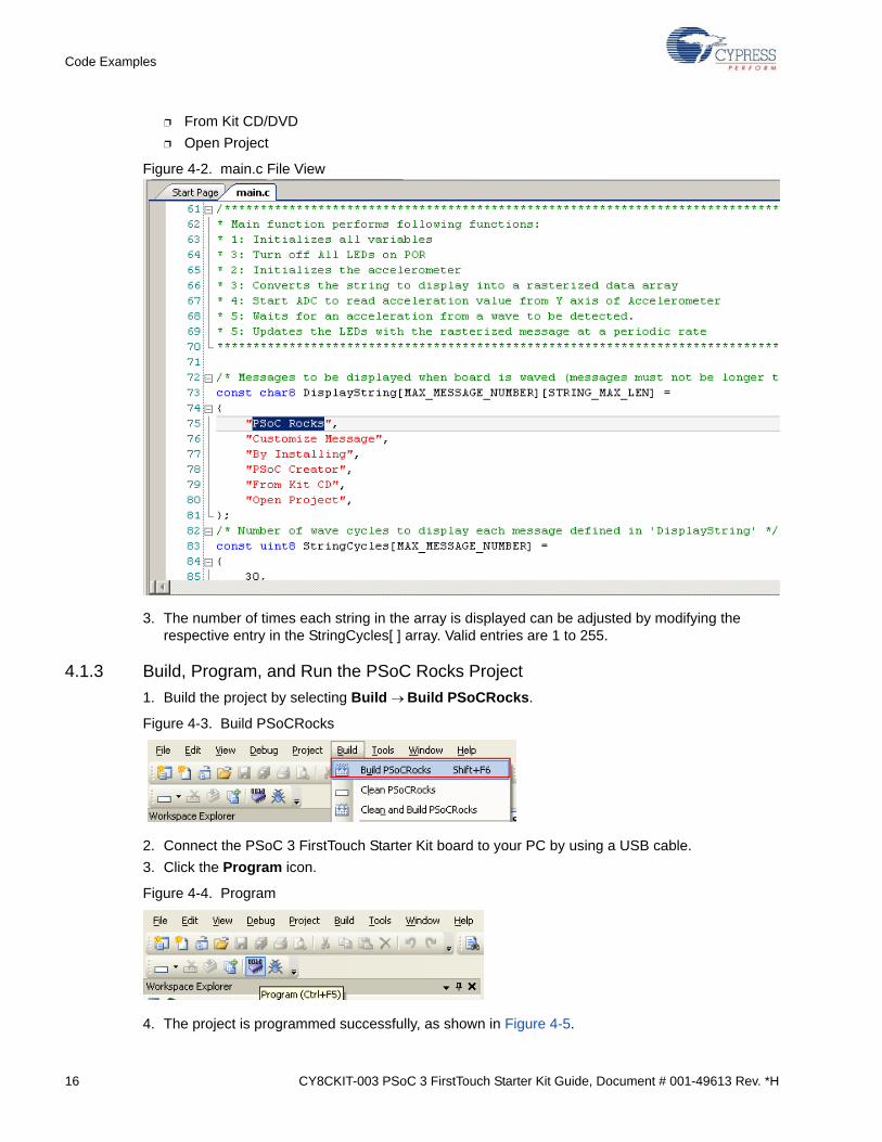
1. From the Workspace Explorer, open the main.c file, as shown in Figure 4-2.
2. Replace the "PSoC Rocks!" string in the DisplayString[ ] [ ] array of strings with "Cypress" or any other message(s) up to 25 characters. By default, it displays the following messages one by one:
❐ PSoC Rocks!
❐ Customize Message
❐ By Installing
❐ PSoC Creator
16 CY8CKIT-003 PSoC 3 FirstTouch Starter Kit Guide, Document # 001-49613 Rev. *H
Code Examples
❐ From Kit CD/DVD
❐ Open Project
Figure 4-2. main.c File View
3. The number of times each string in the array is displayed can be adjusted by modifying the respective entry in the StringCycles[ ] array. Valid entries are 1 to 255.
4.1.3 Build, Program, and Run the PSoC Rocks Project
1. Build the project by selecting Build Build PSoCRocks.
Figure 4-3. Build PSoCRocks
2. Connect the PSoC 3 FirstTouch Starter Kit board to your PC by using a USB cable.
3. Click the Program icon.
Figure 4-4. Program
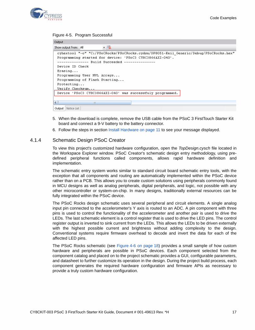
4. The project is programmed successfully, as shown in Figure 4-5.
CY8CKIT-003 PSoC 3 FirstTouch Starter Kit Guide, Document # 001-49613 Rev. *H 17
Code Examples
Figure 4-5. Program Successful
5. When the download is complete, remove the USB cable from the PSoC 3 FirstTouch Starter Kit board and connect a 9-V battery to the battery connector.
6. Follow the steps in section Install Hardware on page 11 to see your message displayed.
4.1.4 Schematic Design PSoC Creator
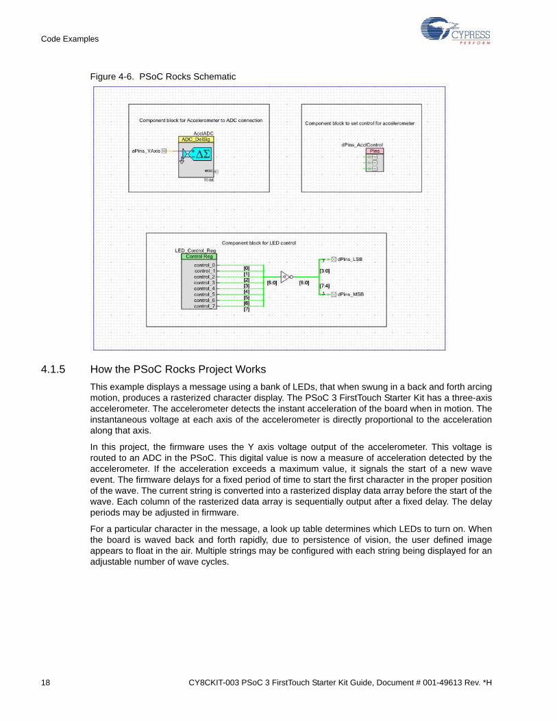
To view this project's customized hardware configuration, open the TopDesign.cysch file located inthe Workspace Explorer window. PSoC Creator's schematic design entry methodology, using pre-defined peripheral functions called components, allows rapid hardware definition andimplementation.
The schematic entry system works similar to standard circuit board schematic entry tools, with theexception that all components and routing are automatically implemented within the PSoC devicerather than on a PCB. This allows you to create custom solutions using peripherals commonly foundin MCU designs as well as analog peripherals, digital peripherals, and logic, not possible with anyother microcontroller or system-on-chip. In many designs, traditionally external resources can befully integrated within the PSoC device.
The PSoC Rocks design schematic uses several peripheral and circuit elements. A single analoginput pin connected to the accelerometer's Y axis is routed to an ADC. A pin component with threepins is used to control the functionality of the accelerometer and another pair is used to drive theLEDs. The last schematic element is a control register that is used to drive the LED pins. The controlregister output is inverted to sink current from the LEDs. This allows the LEDs to be driven externallywith the highest possible current and brightness without adding complexity to the design.Conventional systems require firmware overhead to decode and invert the data for each of theaffected LED pins.
The PSoC Rocks schematic (see Figure 4-6 on page 18) provides a small sample of how customhardware and peripherals are possible in PSoC devices. Each component selected from thecomponent catalog and placed on to the project schematic provides a GUI, configurable parameters,and datasheet to further customize its operation in the design. During the project build process, eachcomponent generates the required hardware configuration and firmware APIs as necessary toprovide a truly custom hardware configuration.
18 CY8CKIT-003 PSoC 3 FirstTouch Starter Kit Guide, Document # 001-49613 Rev. *H
Code Examples
Figure 4-6. PSoC Rocks Schematic
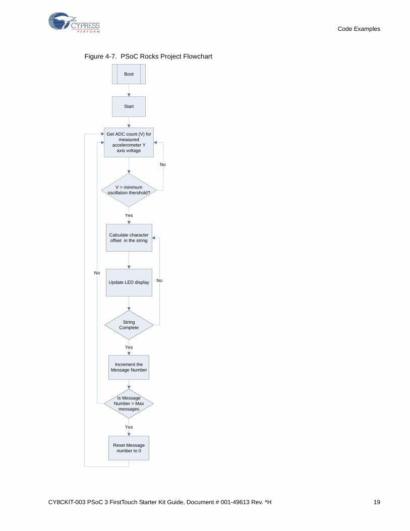
4.1.5 How the PSoC Rocks Project Works
This example displays a message using a bank of LEDs, that when swung in a back and forth arcingmotion, produces a rasterized character display. The PSoC 3 FirstTouch Starter Kit has a three-axisaccelerometer. The accelerometer detects the instant acceleration of the board when in motion. Theinstantaneous voltage at each axis of the accelerometer is directly proportional to the accelerationalong that axis.
In this project, the firmware uses the Y axis voltage output of the accelerometer. This voltage isrouted to an ADC in the PSoC. This digital value is now a measure of acceleration detected by theaccelerometer. If the acceleration exceeds a maximum value, it signals the start of a new waveevent. The firmware delays for a fixed period of time to start the first character in the proper positionof the wave. The current string is converted into a rasterized display data array before the start of thewave. Each column of the rasterized data array is sequentially output after a fixed delay. The delayperiods may be adjusted in firmware.
For a particular character in the message, a look up table determines which LEDs to turn on. Whenthe board is waved back and forth rapidly, due to persistence of vision, the user defined imageappears to float in the air. Multiple strings may be configured with each string being displayed for anadjustable number of wave cycles.
CY8CKIT-003 PSoC 3 FirstTouch Starter Kit Guide, Document # 001-49613 Rev. *H 19
Code Examples
Figure 4-7. PSoC Rocks Project Flowchart
Boot
Start
Get ADC count (V) for measured
accelerometer Y axis voltage
V > minimum oscillation thershold?
Calculate character offset in the string
Update LED display
String Complete
Yes
No
No
Increment the Message Number
Is Message Number > Max
messages
Reset Message number to 0
Yes
Yes
No
20 CY8CKIT-003 PSoC 3 FirstTouch Starter Kit Guide, Document # 001-49613 Rev. *H
Code Examples
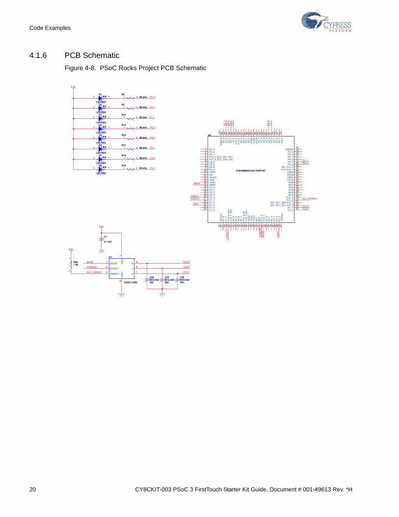
4.1.6 PCB Schematic
Figure 4-8. PSoC Rocks Project PCB Schematic
P2_0
P4_3
P4_2
P4_1
P4_0
P2_3
P2_2
P2_1
ACC_ENABLE
P4_0
SWDCK
P2_1
P2_3
ZOUTSWV
P4_1
P4_3
LOW
BATT
P4_2
SWDIO
ST/M
OD
EM
OD
E
/XRES
P2_0
P2_2
YOUT
MODE
ACC_ENABLE
ST/MODE
XOU
T
XOUT
YOUT
ZOUT
3.3V
3.3V
3.3V
0402 DNI
C29NOLOAD
0402 DNI
C29NOLOAD
0402
R1768 ohm
0402
R1768 ohm1 2
0603
D1
LED RED0603
D1
LED RED
2 1
0402
C1
0.1 uFd0402
C1
0.1 uFd
0603
D5
LED RED0603
D5
LED RED
2 1
0402
R1868 ohm
0402
R1868 ohm1 2
U1
KXSC7-2050
U1
KXSC7-2050
VD
D1
MODE2
ST/MOT3
ENABLE4
X5
Y6
Z7
GN
D8
0402
R1968 ohm
0402
R1968 ohm1 2
0402 DNI
C30NOLOAD
0402 DNI
C30NOLOAD
0603
D7
LED RED0603
D7
LED RED
2 1
0603
D2
LED RED0603
D2
LED RED
2 1
U2
CY8C3866AXI-040 TQFP100
U2
CY8C3866AXI-040 TQFP100
P2_51
P2_62
P2_73
P12_4 I2C0_SCL, SIO4
P12_5 I2C0_SDA, SIO5
P6_46
P6_57
P6_68
P6_79
VSSb10
Ind11
Vboost12
Vbat13
VSSd14
XRES15
P5_016
P5_117
P5_218
P5_319
P1_020
P1_121
P1_222
P1_323
P1_424
P1_525
VD
Dio
126
P1_
627
P1_
728
P12
_6_S
IO29
P12
_7_S
IO30
P5_
431
P5_
532
P5_
633
P5_
734
P15
_6 D
P35
P15
_7 D
M36
VD
Dd
37
VS
Sd
38
VC
Cd
39
NC
140
NC
241
P15
_042
P15
_143
P3_
044
P3_
145
P3_
246
P3_
347
P3_
448
P3_
549
VD
Dio
350
VDDio075
P0_374
P0_273
P0_172
P0_071
P4_170
P4_069
SIO_P12_368
SIO_P12_267
VSSd66
VDDa65
VSSa64
VCCa63
NC862
NC761
NC660
NC559
NC458
NC357
P15_356
P15_255
SIO, I2C1_SDA P12_154
SIO, I2C1_SCL P12_053
P3_752
P3_651
P2_
499
P2_
398
P2_
297
P2_
196
P2_
095
P15
_594
P15
_493
P6_
392
P6_
291
P6_
190
P6_
089
VD
Dd
88
VS
Sd
87
VC
Cd
86
P4_
785
P4_
684
P4_
583
P4_
482
P4_
381
P4_
280
P0_
779
P0_
678
P0_
577
P0_
476
VD
Dio
210
0
0603
D4
LED RED0603
D4
LED RED
2 1
0402
R768 ohm
0402
R768 ohm1 2
0603
D6
LED RED0603
D6
LED RED
2 1
0402 DNI
C25NOLOAD
0402 DNI
C25NOLOAD
0402
R1068 ohm
0402
R1068 ohm1 2
0402
R268 ohm
0402
R268 ohm1 2
0402
R1368 ohm
0402
R1368 ohm1 2
0402
R351.5K0
402
R351.5K
12
0603
D8
LED RED0603
D8
LED RED
2 1
0402
R1668 ohm
0402
R1668 ohm1 2
0603
D3
LED RED0603
D3
LED RED
2 1
CY8CKIT-003 PSoC 3 FirstTouch Starter Kit Guide, Document # 001-49613 Rev. *H 21
Code Examples
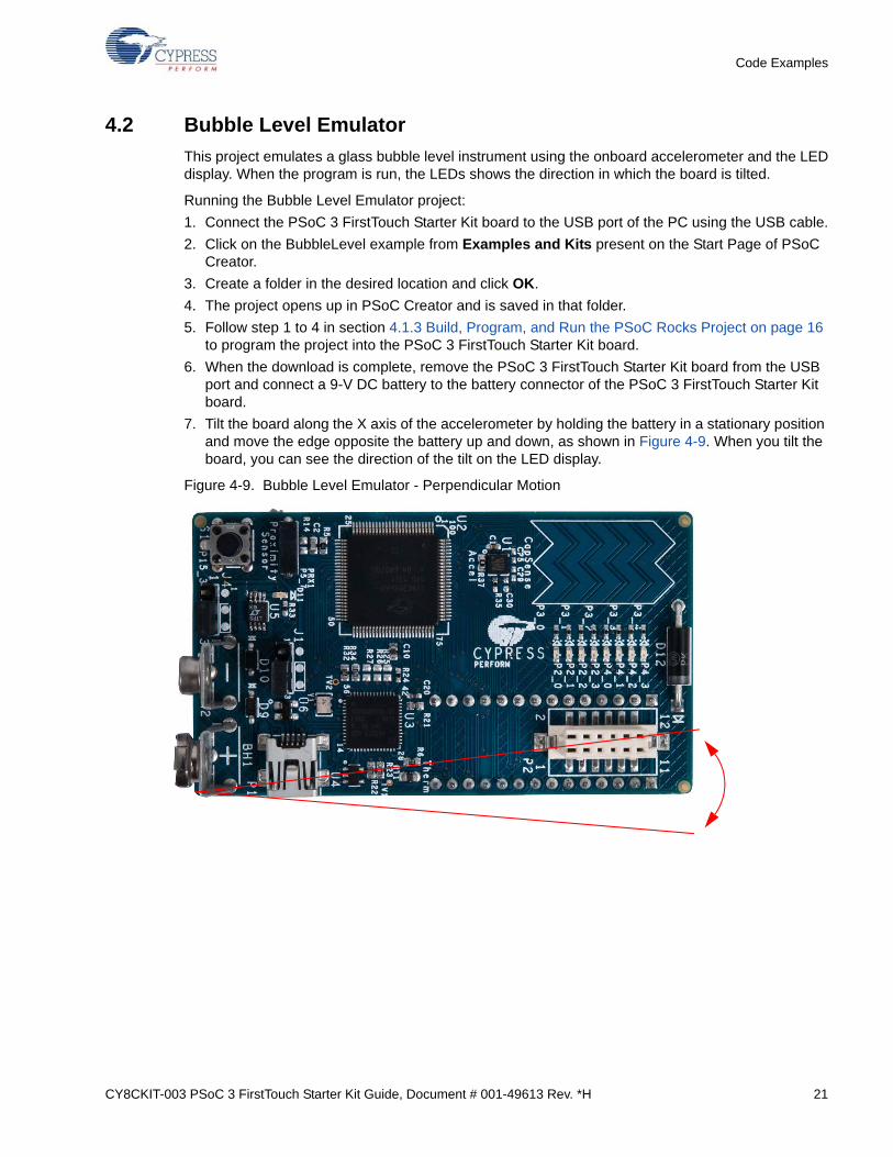
4.2 Bubble Level Emulator
This project emulates a glass bubble level instrument using the onboard accelerometer and the LEDdisplay. When the program is run, the LEDs shows the direction in which the board is tilted.
Running the Bubble Level Emulator project:
1. Connect the PSoC 3 FirstTouch Starter Kit board to the USB port of the PC using the USB cable.
2. Click on the BubbleLevel example from Examples and Kits present on the Start Page of PSoC Creator.
3. Create a folder in the desired location and click OK.
4. The project opens up in PSoC Creator and is saved in that folder.
5. Follow step 1 to 4 in section 4.1.3 Build, Program, and Run the PSoC Rocks Project on page 16 to program the project into the PSoC 3 FirstTouch Starter Kit board.
6. When the download is complete, remove the PSoC 3 FirstTouch Starter Kit board from the USB port and connect a 9-V DC battery to the battery connector of the PSoC 3 FirstTouch Starter Kit board.
7. Tilt the board along the X axis of the accelerometer by holding the battery in a stationary position and move the edge opposite the battery up and down, as shown in Figure 4-9. When you tilt the board, you can see the direction of the tilt on the LED display.
Figure 4-9. Bubble Level Emulator - Perpendicular Motion
22 CY8CKIT-003 PSoC 3 FirstTouch Starter Kit Guide, Document # 001-49613 Rev. *H
Code Examples
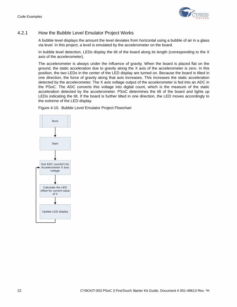
4.2.1 How the Bubble Level Emulator Project Works
A bubble level displays the amount the level deviates from horizontal using a bubble of air in a glassvia level. In this project, a level is emulated by the accelerometer on the board.
In bubble level detection, LEDs display the tilt of the board along its length (corresponding to the Xaxis of the accelerometer).
The accelerometer is always under the influence of gravity. When the board is placed flat on theground, the static acceleration due to gravity along the X axis of the accelerometer is zero. In thisposition, the two LEDs in the center of the LED display are turned on. Because the board is tilted inone direction, the force of gravity along that axis increases. This increases the static accelerationdetected by the accelerometer. The X axis voltage output of the accelerometer is fed into an ADC inthe PSoC. The ADC converts this voltage into digital count, which is the measure of the staticacceleration detected by the accelerometer. PSoC determines the tilt of the board and lights upLEDs indicating the tilt. If the board is further tilted in one direction, the LED moves accordingly tothe extreme of the LED display.
Figure 4-10. Bubble Level Emulator Project Flowchart
Boot
Start
Get ADC count(V) for Accelerometer X axis
voltage
Calculate the LED offset for current value
of V
Update LED display
CY8CKIT-003 PSoC 3 FirstTouch Starter Kit Guide, Document # 001-49613 Rev. *H 23
Code Examples
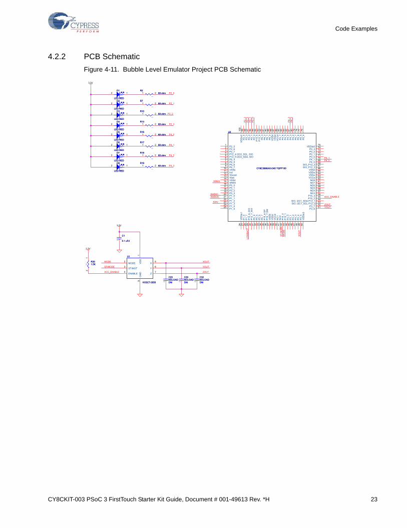
4.2.2 PCB Schematic
Figure 4-11. Bubble Level Emulator Project PCB Schematic
P2_0
P4_3
P4_2
P4_1
P4_0
P2_3
P2_2
P2_1
ACC_ENABLE
P4_0
SWDCK
P2_1
P2_3
ZOUTSWV
P4_1
P4_3
LOW
BATT
P4_2
SWDIO
ST/M
OD
EM
OD
E
/XRES
P2_0
P2_2
YOUT
MODE
ACC_ENABLE
ST/MODE
XOU
T
XOUT
YOUT
ZOUT
3.3V
3.3V
3.3V
0603
D7
LED RED0603
D7
LED RED
2 1
0402
R268 ohm
0402
R268 ohm1 2
0603
D5
LED RED0603
D5
LED RED
2 1
0402
R1068 ohm
0402
R1068 ohm1 2
U2
CY8C3866AXI-040 TQFP100
U2
CY8C3866AXI-040 TQFP100
P2_51
P2_62
P2_73
P12_4 I2C0_SCL, SIO4
P12_5 I2C0_SDA, SIO5
P6_46
P6_57
P6_68
P6_79
VSSb10
Ind11
Vboost12
Vbat13
VSSd14
XRES15
P5_016
P5_117
P5_218
P5_319
P1_020
P1_121
P1_222
P1_323
P1_424
P1_525
VD
Dio
126
P1_
627
P1_
728
P12
_6_S
IO29
P12
_7_S
IO30
P5_
431
P5_
532
P5_
633
P5_
734
P15
_6 D
P35
P15
_7 D
M36
VD
Dd
37
VS
Sd
38
VC
Cd
39
NC
140
NC
241
P15
_042
P15
_143
P3_
044
P3_
145
P3_
246
P3_
347
P3_
448
P3_
549
VD
Dio
350
VDDio075
P0_374
P0_273
P0_172
P0_071
P4_170
P4_069
SIO_P12_368
SIO_P12_267
VSSd66
VDDa65
VSSa64
VCCa63
NC862
NC761
NC660
NC559
NC458
NC357
P15_356
P15_255
SIO, I2C1_SDA P12_154
SIO, I2C1_SCL P12_053
P3_752
P3_651
P2_
499
P2_
398
P2_
297
P2_
196
P2_
095
P15
_594
P15
_493
P6_
392
P6_
291
P6_
190
P6_
089
VD
Dd
88
VS
Sd
87
VC
Cd
86
P4_
785
P4_
684
P4_
583
P4_
482
P4_
381
P4_
280
P0_
779
P0_
678
P0_
577
P0_
476
VD
Dio
210
0
0603
D3
LED RED0603
D3
LED RED
2 1
U1
KXSC7-2050
U1
KXSC7-2050
VD
D1
MODE2
ST/MOT3
ENABLE4
X5
Y6
Z7
GN
D8
0402
R1668 ohm
0402
R1668 ohm1 2
0402
R1868 ohm
0402
R1868 ohm1 2
0402 DNI
C25NOLOAD
0402 DNI
C25NOLOAD
0603
D8
LED RED0603
D8
LED RED
2 1
0402
R768 ohm
0402
R768 ohm1 2
0603
D6
LED RED0603
D6
LED RED
2 1
0402 DNI
C29NOLOAD
0402 DNI
C29NOLOAD
0402
C1
0.1 uFd0402
C1
0.1 uFd
0603
D4
LED RED0603
D4
LED RED
2 1
0402
R1368 ohm
0402
R1368 ohm1 2
0603
D2
LED RED0603
D2
LED RED
2 1
0603
D1
LED RED0603
D1
LED RED
2 1
0402
R1768 ohm
0402
R1768 ohm1 2
0402 DNI
C30NOLOAD
0402 DNI
C30NOLOAD
0402
R1968 ohm
0402
R1968 ohm1 2
0402
R351.5K0
402
R351.5K
12

24 CY8CKIT-003 PSoC 3 FirstTouch Starter Kit Guide, Document # 001-49613 Rev. *H
Code Examples
4.3 ThermistorTemperatureSense
This project measures the current room temperature and displays it as a rasterized image when theboard is waved.
Running the ThermistorTemperatureSense project:
1. Connect the PSoC 3 FirstTouch Starter Kit board to the USB port of the PC through the USB cable.
2. Click on the ThemistorTemperatureSense example from Examples and Kits on the Start Page of PSoC Creator.
3. Create a folder in the desired location and click OK.
4. Te project opens up in PSoC Creator and is saved in that folder.
5. Follow step 1 to 4 in section Build, Program, and Run the PSoC Rocks Project on page 16 to pro-gram the project into the PSoC 3 FirstTouch Starter Kit board.
6. When the download is complete, remove the PSoC 3 FirstTouch Starter Kit board from the USB port and connect a 9-V DC battery to the battery connector of the PSoC 3 FirstTouch Starter Kit board.
7. Hold the board and wave it continuously from left to right, as shown in Figure 3-1 on page 11. A rasterized image of the current measured temperature in degree Celsius is visible in the air. Press the S1 switch while waving the board to toggle the temperature from Celsius to Fahrenheit and vice-versa.
4.3.1 How the ThermistorTemperatureSense Project Works
The thermistor example demonstrates how the PSoC device senses temperature using a thermistor.The thermistor resistance varies with temperature following a predictable nonlinear curve. Thetemperature-resistance relationship is given by the Steinhart-Hart equation:
1 /Tk = A + B*ln(R) + C*(ln(R))3
In this equation:
■ A, B, and C are empirical constants known as Steinhart-Hart coefficients.
■ R is the resistance of the thermistor in Ohms.
■ Tk is the temperature in degree Kelvins.
The same equation, when converted to Celsius scale becomes:
Tc = Tk - 273.15
In this equation, Tc is the temperature in degree Celsius.
CY8CKIT-003 PSoC 3 FirstTouch Starter Kit Guide, Document # 001-49613 Rev. *H 25
Code Examples
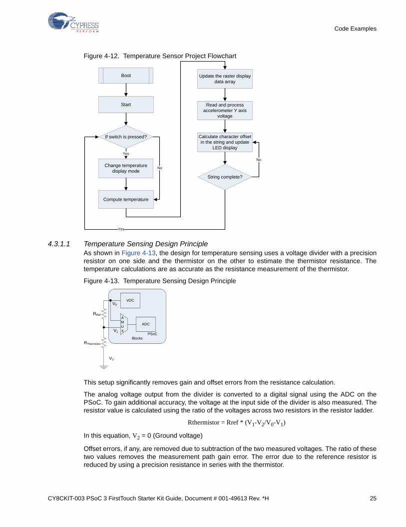
Figure 4-12. Temperature Sensor Project Flowchart
4.3.1.1 Temperature Sensing Design Principle As shown in Figure 4-13, the design for temperature sensing uses a voltage divider with a precisionresistor on one side and the thermistor on the other to estimate the thermistor resistance. Thetemperature calculations are as accurate as the resistance measurement of the thermistor.
Figure 4-13. Temperature Sensing Design Principle
This setup significantly removes gain and offset errors from the resistance calculation.
The analog voltage output from the divider is converted to a digital signal using the ADC on thePSoC. To gain additional accuracy, the voltage at the input side of the divider is also measured. Theresistor value is calculated using the ratio of the voltages across two resistors in the resistor ladder.
Rthermistor = Rref * (V1-V2/V0-V1)
In this equation, V2 = 0 (Ground voltage)
Offset errors, if any, are removed due to subtraction of the two measured voltages. The ratio of thesetwo values removes the measurement path gain error. The error due to the reference resistor isreduced by using a precision resistance in series with the thermistor.
Boot
Start
String complete?
Yes
Change temperature display mode
Compute temperature
Update the raster display data array
Read and process accelerometer Y axis
voltage
Calculate character offset in the string and update
LED display
If switch is pressed?
No
No
Yes
PSoC Blocks
RRef
RThermistor
V2
V1
V0
AMUX
ADC
VDC
26 CY8CKIT-003 PSoC 3 FirstTouch Starter Kit Guide, Document # 001-49613 Rev. *H
Code Examples
Temperature is calculated by referring to a table of 165 known points on the resistance/temperaturecurve using a look up table. The table holds resistance values of the thermistor from –40 °C to125 °C, in 1-°C increments. Linear interpolation is used between the points in the table fortemperature calculation up to two decimal places.
The temperature is then displayed as a rasterized image using persistence of vision when the boardis waved around. See section How the PSoC Rocks Project Works on page 18 to understand howthe message is displayed on the LEDs.
For more information on using PSoC family devices with a thermistor, see the application notesAN2017 – PSoC(R) 1 Thermistor-Based Thermometer and AN66477 – PSoC(R) 3 and PSoC 5Temperature Measurement with Thermistor.
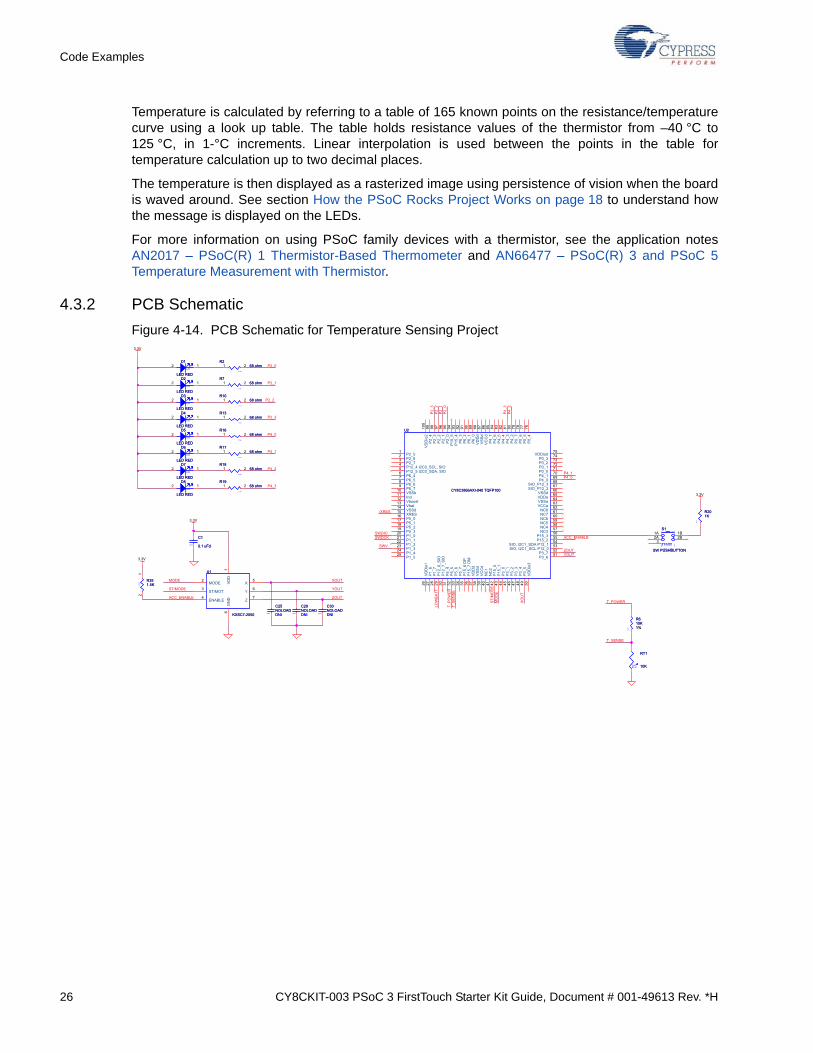
4.3.2 PCB Schematic
Figure 4-14. PCB Schematic for Temperature Sensing Project
P2_0
P4_3
P4_2
P4_1
P4_0
P2_3
P2_2
P2_1
ACC_ENABLE
P4_0
SWDCK
P2_1
XOU
T
P2_3
ZOUTSWV
T_SENSE
P4_1
P4_3
LOW
BATT
P4_2
SWDIO
ST/M
OD
E
T_POWERMO
DE
/XRES
P2_0
P2_2
YOUT
T_PO
WER
T_SE
NSE
XOUT
YOUT
ZOUTACC_ENABLE
ST/MODE
MODE
3.3V
3.3V
3.3V
3.3V
0603
D7
LED RED0603
D7
LED RED
2 1
0402
R268 ohm
0402
R268 ohm1 2
0603
D5
LED RED0603
D5
LED RED
2 1
0402
R1068 ohm
0402
R1068 ohm1 2
U2
CY8C3866AXI-040 TQFP100
U2
CY8C3866AXI-040 TQFP100
P2_51
P2_62
P2_73
P12_4 I2C0_SCL, SIO4
P12_5 I2C0_SDA, SIO5
P6_46
P6_57
P6_68
P6_79
VSSb10
Ind11
Vboost12
Vbat13
VSSd14
XRES15
P5_016
P5_117
P5_218
P5_319
P1_020
P1_121
P1_222
P1_323
P1_424
P1_525
VD
Dio
126
P1_
627
P1_
728
P12
_6_S
IO29
P12
_7_S
IO30
P5_
431
P5_
532
P5_
633
P5_
734
P15
_6 D
P35
P15
_7 D
M36
VD
Dd
37
VS
Sd
38
VC
Cd
39
NC
140
NC
241
P15
_042
P15
_143
P3_
044
P3_
145
P3_
246
P3_
347
P3_
448
P3_
549
VD
Dio
350
VDDio075
P0_374
P0_273
P0_172
P0_071
P4_170
P4_069
SIO_P12_368
SIO_P12_267
VSSd66
VDDa65
VSSa64
VCCa63
NC862
NC761
NC660
NC559
NC458
NC357
P15_356
P15_255
SIO, I2C1_SDA P12_154
SIO, I2C1_SCL P12_053
P3_752
P3_651
P2_
499
P2_
398
P2_
297
P2_
196
P2_
095
P15
_594
P15
_493
P6_
392
P6_
291
P6_
190
P6_
089
VD
Dd
88
VS
Sd
87
VC
Cd
86
P4_
785
P4_
684
P4_
583
P4_
482
P4_
381
P4_
280
P0_
779
P0_
678
P0_
577
P0_
476
VD
Dio
210
0
0603
D3
LED RED0603
D3
LED RED
2 1
U1
KXSC7-2050
U1
KXSC7-2050
VD
D1
MODE2
ST/MOT3
ENABLE4
X5
Y6
Z7
GN
D8
0402
R1668 ohm
0402
R1668 ohm1 2
0402
R1868 ohm
0402
R1868 ohm1 2
0402 DNI
C25NOLOAD
0402 DNI
C25NOLOAD
25
RT1
10K25
RT1
10K
0603
R201K
0603
R201K
FRAME
S1
SW PUSHBUTTON
FRAME
S1
SW PUSHBUTTON
1A2A
1B2B
3
0603
D8
LED RED0603
D8
LED RED
2 1
0402
R768 ohm
0402
R768 ohm1 2
0603
D6
LED RED0603
D6
LED RED
2 1
0402 DNI
C29NOLOAD
0402 DNI
C29NOLOAD
0402
C1
0.1 uFd0402
C1
0.1 uFd
0603
D4
LED RED0603
D4
LED RED
2 1
0402
R1368 ohm
0402
R1368 ohm1 2
0603
D2
LED RED0603
D2
LED RED
2 1
0603
D1
LED RED0603
D1
LED RED
2 1
0402
R1768 ohm
0402
R1768 ohm1 2
0402 DNI
C30NOLOAD
0402 DNI
C30NOLOAD
0402
R1968 ohm
0402
R1968 ohm1 2
0603
R610K1%
0603
R610K1%
0402
R351.5K0
402
R351.5K
12

CY8CKIT-003 PSoC 3 FirstTouch Starter Kit Guide, Document # 001-49613 Rev. *H 27
Code Examples
4.4 CapSense Slider
This project shows how to detect the position of a finger on the CapSense slider of the PSoC 3 First-Touch Starter Kit board and indicate its position on the LED display.
Running the CapSense project:
1. Connect the PSoC 3 FirstTouch Starter Kit board to the USB port of the PC through the USB cable.
2. Click on the CapSenseSlider example from Examples and Kits on the Start Page of PSoC Cre-ator.
3. Create a folder in the desired location and click OK.
4. The project opens up in PSoC Creator and is saved in that folder.
5. Follow step 1 to 4 in section Build, Program, and Run the PSoC Rocks Project on page 16 to pro-gram the project into the PSoC 3 FirstTouch Starter Kit board.
6. When the download is complete, remove the PSoC 3 FirstTouch Starter Kit board from the USB port and connect a 9-V DC battery to the battery connector of the PSoC 3 FirstTouch Starter Kit board.
7. Move your finger along the CapSense Slider and see the corresponding LEDs light up.
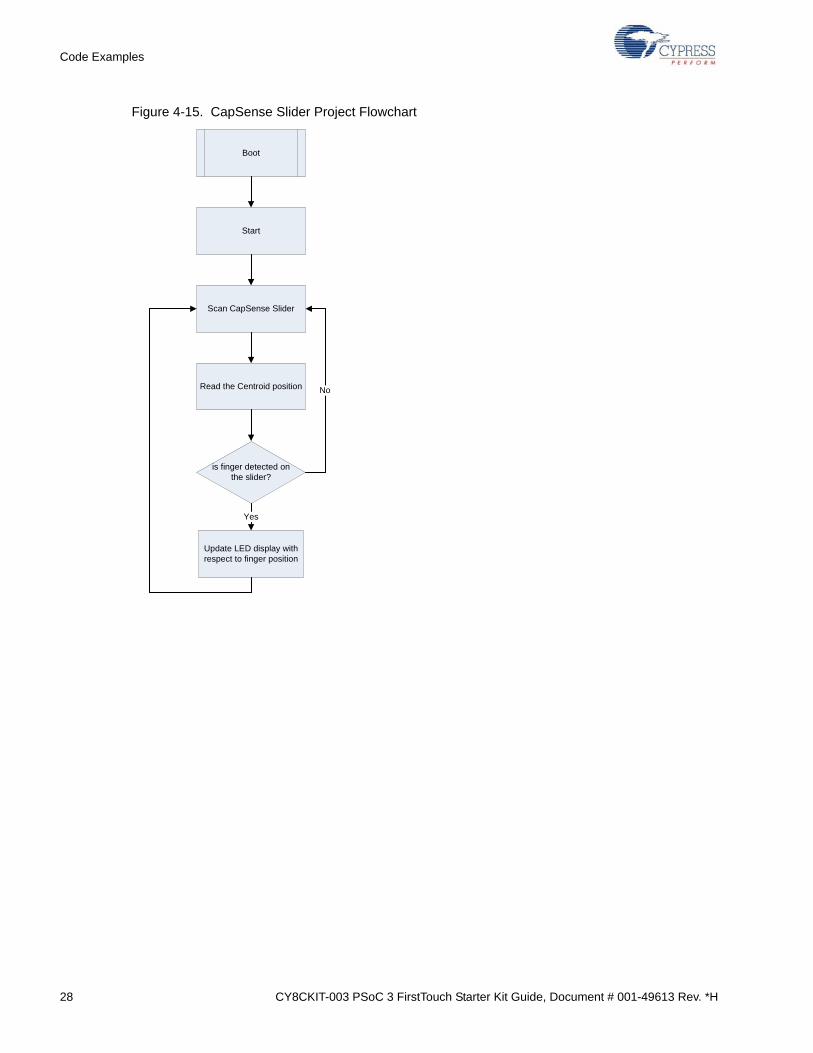
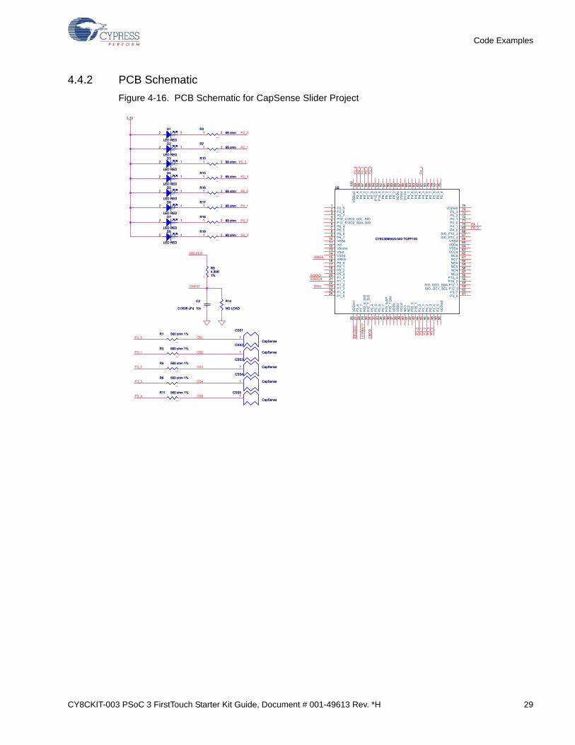
4.4.1 How the CapSense Slider Project Works
Capacitive sensing determines the presence of a conductive element, such as the finger, on acapacitive sensor incorporated on the PCB. The kit consists of a bank of CapSense sensors in theform of a slider. The size of the sensors and their position is designed such that when a finger isplaced on any part of the slider, at least three sensors are active (it detects the presence of the fingerby a change in its capacitance value).
The CapSense component provides APIs, which report the centroid (relative position) of the fingeron the slider based on the active sensors. The firmware then lights up the LED corresponding to thiscentroid position.
28 CY8CKIT-003 PSoC 3 FirstTouch Starter Kit Guide, Document # 001-49613 Rev. *H
Code Examples
Figure 4-15. CapSense Slider Project Flowchart
Boot
Start
Scan CapSense Slider
Read the Centroid position
is finger detected on the slider?
Update LED display with respect to finger position
Yes
No
CY8CKIT-003 PSoC 3 FirstTouch Starter Kit Guide, Document # 001-49613 Rev. *H 29
Code Examples
4.4.2 PCB Schematic
Figure 4-16. PCB Schematic for CapSense Slider Project
P3_2
P3_1
P3_0
P3_4
P3_3
CS1
CS2
CS3
CS4
CS5
P2_0
P4_3
P4_2
P4_1
P4_0
P2_3
P2_2
P2_1
P4_0
SWDCK
P2_1
P2_3
P3_0
SWV
P2_4
P4_1
RBL
EED
P4_3
LOW
BATT
P3_1
RBLEED
SWDIO
P3_3
P3_2
/XRES
P3_4
P2_0
P2_2
CMOD
CM
OD
3.3V
CSS3
CapSense
CSS3
CapSense1
0603
R4 560 ohm 1%
0603
R4 560 ohm 1%
0402
R268 ohm
0402
R268 ohm1 2
0603
D7
LED RED0603
D7
LED RED
2 1
0603
R8 560 ohm 1%
0603
R8 560 ohm 1%
0603
C2
0.0039 uFd 10v 0603
C2
0.0039 uFd 10v
0402
R1068 ohm
0402
R1068 ohm1 2
0603
D5
LED RED0603
D5
LED RED
2 1
0603
R54.99K1%
0603
R54.99K1%
U2
CY8C3866AXI-040 TQFP100
U2
CY8C3866AXI-040 TQFP100
P2_51
P2_62
P2_73
P12_4 I2C0_SCL, SIO4
P12_5 I2C0_SDA, SIO5
P6_46
P6_57
P6_68
P6_79
VSSb10
Ind11
Vboost12
Vbat13
VSSd14
XRES15
P5_016
P5_117
P5_218
P5_319
P1_020
P1_121
P1_222
P1_323
P1_424
P1_525
VD
Dio
126
P1_
627
P1_
728
P12
_6_S
IO29
P12
_7_S
IO30
P5_
431
P5_
532
P5_
633
P5_
734
P15
_6 D
P35
P15
_7 D
M36
VD
Dd
37
VS
Sd
38
VC
Cd
39
NC
140
NC
241
P15
_042
P15
_143
P3_
044
P3_
145
P3_
246
P3_
347
P3_
448
P3_
549
VD
Dio
350
VDDio075
P0_374
P0_273
P0_172
P0_071
P4_170
P4_069
SIO_P12_368
SIO_P12_267
VSSd66
VDDa65
VSSa64
VCCa63
NC862
NC761
NC660
NC559
NC458
NC357
P15_356
P15_255
SIO, I2C1_SDA P12_154
SIO, I2C1_SCL P12_053
P3_752
P3_651
P2_
499
P2_
398
P2_
297
P2_
196
P2_
095
P15
_594
P15
_493
P6_
392
P6_
291
P6_
190
P6_
089
VD
Dd
88
VS
Sd
87
VC
Cd
86
P4_
785
P4_
684
P4_
583
P4_
482
P4_
381
P4_
280
P0_
779
P0_
678
P0_
577
P0_
476
VD
Dio
210
0
0603
D3
LED RED0603
D3
LED RED
2 1
0402
R1668 ohm
0402
R1668 ohm1 2
0603
R1 560 ohm 1%
0603
R1 560 ohm 1%
0402
R1868 ohm
0402
R1868 ohm1 2
0603
R11 560 ohm 1%
0603
R11 560 ohm 1%
CSS4
CapSense
CSS4
CapSense1
0603
D8
LED RED0603
D8
LED RED
2 1
0402
R768 ohm
0402
R768 ohm1 2
0603
D6
LED RED0603
D6
LED RED
2 1
CSS2
CapSense
CSS2
CapSense1
0603
D4
LED RED0603
D4
LED RED
2 1
0402
R1368 ohm
0402
R1368 ohm1 2
0603
D2
LED RED0603
D2
LED RED
2 1
0603
D1
LED RED0603
D1
LED RED
2 1
0603
R3 560 ohm 1%
0603
R3 560 ohm 1%
0402
R1768 ohm
0402
R1768 ohm1 2
CSS1
CapSense
CSS1
CapSense1
0603
R14
NO LOAD
0603
R14
NO LOAD
CSS5
CapSense
CSS5
CapSense1
0402
R1968 ohm
0402
R1968 ohm1 2
30 CY8CKIT-003 PSoC 3 FirstTouch Starter Kit Guide, Document # 001-49613 Rev. *H
Code Examples
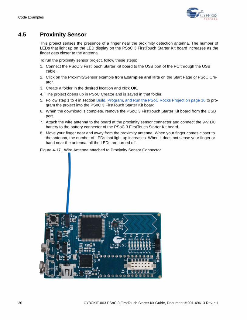
4.5 Proximity Sensor
This project senses the presence of a finger near the proximity detection antenna. The number ofLEDs that light up on the LED display on the PSoC 3 FirstTouch Starter Kit board increases as thefinger gets closer to the antenna.
To run the proximity sensor project, follow these steps:
1. Connect the PSoC 3 FirstTouch Starter Kit board to the USB port of the PC through the USB cable.
2. Click on the ProximitySensor example from Examples and Kits on the Start Page of PSoC Cre-ator.
3. Create a folder in the desired location and click OK.
4. The project opens up in PSoC Creator and is saved in that folder.
5. Follow step 1 to 4 in section Build, Program, and Run the PSoC Rocks Project on page 16 to pro-gram the project into the PSoC 3 FirstTouch Starter Kit board.
6. When the download is complete, remove the PSoC 3 FirstTouch Starter Kit board from the USB port.
7. Attach the wire antenna to the board at the proximity sensor connector and connect the 9-V DC battery to the battery connector of the PSoC 3 FirstTouch Starter Kit board.
8. Move your finger near and away from the proximity antenna. When your finger comes closer to the antenna, the number of LEDs that light up increases. When it does not sense your finger or hand near the antenna, all the LEDs are turned off.
Figure 4-17. Wire Antenna attached to Proximity Sensor Connector
CY8CKIT-003 PSoC 3 FirstTouch Starter Kit Guide, Document # 001-49613 Rev. *H 31
Code Examples
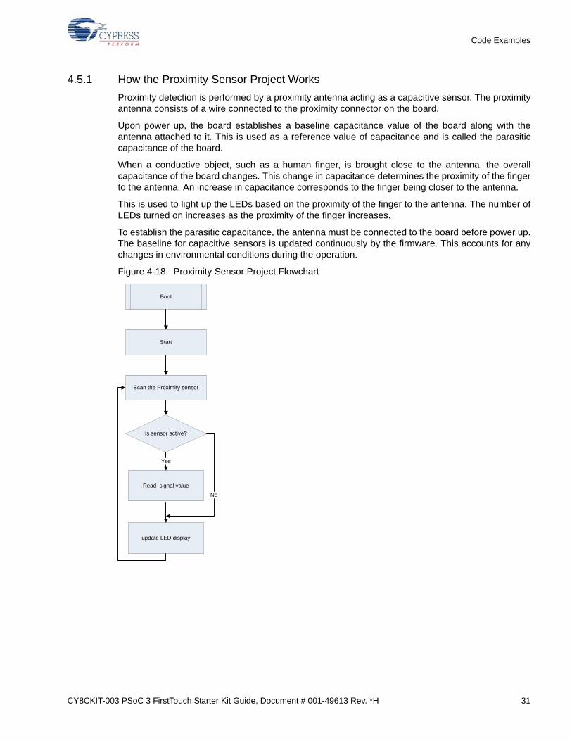
4.5.1 How the Proximity Sensor Project Works
Proximity detection is performed by a proximity antenna acting as a capacitive sensor. The proximityantenna consists of a wire connected to the proximity connector on the board.
Upon power up, the board establishes a baseline capacitance value of the board along with theantenna attached to it. This is used as a reference value of capacitance and is called the parasiticcapacitance of the board.
When a conductive object, such as a human finger, is brought close to the antenna, the overallcapacitance of the board changes. This change in capacitance determines the proximity of the fingerto the antenna. An increase in capacitance corresponds to the finger being closer to the antenna.
This is used to light up the LEDs based on the proximity of the finger to the antenna. The number ofLEDs turned on increases as the proximity of the finger increases.
To establish the parasitic capacitance, the antenna must be connected to the board before power up.The baseline for capacitive sensors is updated continuously by the firmware. This accounts for anychanges in environmental conditions during the operation.
Figure 4-18. Proximity Sensor Project Flowchart
Boot
Start
Scan the Proximity sensor
Is sensor active?
Read signal value
Yes
No
update LED display

32 CY8CKIT-003 PSoC 3 FirstTouch Starter Kit Guide, Document # 001-49613 Rev. *H
Code Examples
4.5.2 PCB Schematic
Figure 4-19. PCB Schematic for Proximity Detection Project
ProximitySensorLoop
P2_0
P4_3
P4_2
P4_1
P4_0
P2_3
P2_2
P2_1
SWDCK
P2_1
P2_3
SWV
P2_4
CM
OD
P4_1
RBL
EED
P4_3
LOW
BATT
RBLEED
SWDIO
CMOD
/XRES
P2_0
P2_2
P4_0
3.3V
0402
R268 ohm
0402
R268 ohm1 2
0603
D7
LED RED0603
D7
LED RED
2 1
0603
C2
0.0039 uFd 10v 0603
C2
0.0039 uFd 10v
0402
R1068 ohm
0402
R1068 ohm1 2
0603
D5
LED RED0603
D5
LED RED
2 1
0603
R54.99K1%
0603
R54.99K1%
U2
CY8C3866AXI-040 TQFP100
U2
CY8C3866AXI-040 TQFP100
P2_51
P2_62
P2_73
P12_4 I2C0_SCL, SIO4
P12_5 I2C0_SDA, SIO5
P6_46
P6_57
P6_68
P6_79
VSSb10
Ind11
Vboost12
Vbat13
VSSd14
XRES15
P5_016
P5_117
P5_218
P5_319
P1_020
P1_121
P1_222
P1_323
P1_424
P1_525
VD
Dio
126
P1_
627
P1_
728
P12
_6_S
IO29
P12
_7_S
IO30
P5_
431
P5_
532
P5_
633
P5_
734
P15
_6 D
P35
P15
_7 D
M36
VD
Dd
37
VS
Sd
38
VC
Cd
39
NC
140
NC
241
P15
_042
P15
_143
P3_
044
P3_
145
P3_
246
P3_
347
P3_
448
P3_
549
VD
Dio
350
VDDio075
P0_374
P0_273
P0_172
P0_071
P4_170
P4_069
SIO_P12_368
SIO_P12_267
VSSd66
VDDa65
VSSa64
VCCa63
NC862
NC761
NC660
NC559
NC458
NC357
P15_356
P15_255
SIO, I2C1_SDA P12_154
SIO, I2C1_SCL P12_053
P3_752
P3_651
P2_
499
P2_
398
P2_
297
P2_
196
P2_
095
P15
_594
P15
_493
P6_
392
P6_
291
P6_
190
P6_
089
VD
Dd
88
VS
Sd
87
VC
Cd
86
P4_
785
P4_
684
P4_
583
P4_
482
P4_
381
P4_
280
P0_
779
P0_
678
P0_
577
P0_
476
VD
Dio
210
0
0603
D3
LED RED0603
D3
LED RED
2 1
0402
R1668 ohm
0402
R1668 ohm1 2
0402
R1868 ohm
0402
R1868 ohm1 2
PRX1RECEPTACLE 1x1PRX1RECEPTACLE 1x1
11
0603
D8
LED RED0603
D8
LED RED
2 1
0402
R768 ohm
0402
R768 ohm1 2
0603
D6
LED RED0603
D6
LED RED
2 1
0603
D4
LED RED0603
D4
LED RED
2 1
0603R31
560 ohm 1%
0603R31
560 ohm 1%
0402
R1368 ohm
0402
R1368 ohm1 2
0603
D2
LED RED0603
D2
LED RED
2 1
0603
D1
LED RED0603
D1
LED RED
2 1
0402
R1768 ohm
0402
R1768 ohm1 2
0603
R14
NO LOAD
0603
R14
NO LOAD
0402
R1968 ohm
0402
R1968 ohm1 2

CY8CKIT-003 PSoC 3 FirstTouch Starter Kit Guide, Document # 001-49613 Rev. *H 33
5. Technical Reference
5.1 PSoC 3 FirstTouch Starter Kit Schematic
Figure 5-1. PSoC 3 FirstTouch Starter Kit Design Schematic
D
C
B
A
TP2
PLACE ONE CAP PER EACH VCC ON U3.
PLACE C21 AND C22 CLOSECLOSE TO U3-3 AND U3-7.
ProximitySensorLoop
REMOVE R33 FOR USBCOMPLIANCE.
ADD R32 AND R34 FORUSB COMPLIANCE.NOTE: REQUIRESFIRMWARE UPDATE.
PCB#:PDCR-9493Assembly:121R-49300
3.3v: J1-2 to J1-3VBUS: J1-1 to J1-2VDDIO: OPEN
VBUS: J4-1 to J4-2VDDIO: J4-1 to J4-2
3.3v: J4-2 to J4-3
DNI DNI DNI
DNI
+/-15kV ESD ProtectionPlace near to the Connector
VBUS
9V_PLUS
9V_PLUS
P3_2
P3_1
P3_0
P3_4
P3_3
CS1
CS2
CS3
CS4
CS5
P2_0
P4_3
P4_2
P4_1
P4_0
P2_3
P2_2
P2_1
/XRES
USBIO/SWDIOUSBIO/SWDCK
VBUS
SWDIO
P12_1P12_0P5_0
P5_1
P5_2P5_3P1_4P1_5P1_7
VBUS
P4
_6
ACC_ENABLE
P4_0
US
BIO
/SW
DC
K
SWDCK
P0
_7
P2
_1
XO
UT
P5_2
P6_5
SWV
P2
_3
ZOUT
P0_1
P3
_0
SWV
P2_6
P4
_7
P12_0
P12_2
P5_3
P6_6
P2
_4
T_SENSE
P12_1
P6
_2
P1
5_
4
CM
OD
P6_7
P2_7
P12_3
P4_1
RB
LE
ED
P5_0
P4
_3
P0_0
P3
_1
P1_4
RBLEED
P0_2
US
BIO
/SW
DIO
CMOD
P4
_2
P4
_4
P6
_1
SWDIO
P2_5
P6
_0
P3
_3
ST
/MO
DE
P0
_6
P6
_3
P3
_2
P1_5
P5_1
T_POWER
P0_3
/XRES
P4
_5
P3
_4
P6_4
SWDCK
P2
_0
P2
_2
YOUT
T_P
OW
ER
P0
_5
P0
_4
P1
_7
VDDIO
VBUS
3.3V
T_
SE
NS
E
XOUT
YOUT
ZOUT
P6_1P6_3P6_5P6_7P12_3P2_7
P0_1P0_3P0_5P0_7P4_5P4_7
P6_0P6_2P6_4P6_6P12_2P2_6
P0_0P0_2P0_4P0_6P4_4P4_6
ST/MODE
ACC_ENABLE
DMDP
3.3V_REG
3.3V
3.3V
3.3V
3.3V
VDDIO
VDDIO
VDDIO
VDDIO
VDDIO
3.3V
3.3V
3.3V
3.3V
3.3V
3.3V
3.3V
3.3V
VCCd
VCCd
3.3V
VDDIO
3.3V
3.3V
3.3V
VDDIO
3.3V
Title
Size Document Number Rev
CYPRESS SEMICONDUCTOR © 2012
REF-14883 *C
CY8CKIT-003 PSoC 3 FirstTouch Starter Kit
C
Title
Size Document Number Rev
CYPRESS SEMICONDUCTOR © 2012
REF-14883 *C
CY8CKIT-003 PSoC 3 FirstTouch Starter Kit
C
Title
Size Document Number Rev
CYPRESS SEMICONDUCTOR © 2012
REF-14883 *C
CY8CKIT-003 PSoC 3 FirstTouch Starter Kit
C
0402 DNI
C29NOLOAD
0402
C13
0.1 uFd
Y124 MHz
13
2
0603
R25100K1%
0402
C14
0.1 uFd
U3
CY7C68013A-56LTXC
RE
SE
RV
ED
14
WAKEUP#44
PA1/nINT134
SCL15
VC
C5
43
SDA16
PA2/SLOE35
VC
C3
17
PA3/WU236
VC
C4
27
PA4/FIFOADR037
PA5/FIFOADR138
AVCC13
PA6/PKTEND39
GN
D3
26
PA7/FLAGD40
GN
D4
28
PB0/FD018
GN
D6
56
AG
ND
16
XT
AL
IN5
XT
AL
OU
T4
PA0/nINT033
PB1/FD119
PB2/FD220
PB3/FD321
PB4/FD422
PB5/FD523
PB6/FD624
PB7/FD725
DPLUS8 DMINUS9
CLKOUT54
RESET#42
VC
C6
55
RDY0/SLRD1
RDY1/SLWR2
CTL0/FLAGA29
CTL1/FLAGB30
CTL2/FLAGC31
IFCLK13
PD0/FD845
PD1/FD946
PD2/FD1047
PD3/FD1148
PD4/FD1249
PD5/FD1350
PD6/FD1451
PD7/FD1552
VC
C1
11
VC
C2
32
GN
D1
12
GN
D2
41
AG
ND
210
AVCC27
GN
D5
53
CP
57
0402
R1768 ohm1 2
0603
D1
LED RED
2 1
0402
C8
0.1 uFd
0402
C1
0.1 uFd
0603
R21100K1%
J3
HDR 14x1
11
22
33
44
55
66
77
88
99
1010
1111
1212
1313
1414
0402
C15
0.1 uFd
0603
D5
LED RED
2 1
0402
C18
0.1 uFd
0603
R14
NO LOAD
0402
C6
0.1 uFd
0603
C231.0 uFd
CSS4
CapSense1
0402
R1868 ohm1 2
0402
C16
0.1 uFd
P1
USB MINI B
VBUS1
DM2
DP3
GND5ID4
S1
6
S2
7S
38
S4
9
0603
R23100K1%
0402
C17
0.1 uFd
0402
C19
0.1 uFd
0603
R30
ZERO
U5 LT1962EMS8-3.3
IN8
nSHDN5
OUT1
SENSE2
Byp3
GN
D4
GN
D1
6
GN
D2
7
0402
R1968 ohm1 2
0402 DNI
C30NOLOAD
0603
R3239K1%
12
FRAME
S1
SW PUSHBUTTON
1A2A
1B2B
3
P2
6x2 RECP 2mm SMT
11
33
55
77
99
1111
22
44
66
88
1010
1212
0603
R1 560 ohm 1%
0603
R27100K1%
0603
D7
LED RED
2 1
9V
BH2BAT 9V MALE
NEG1
T-18 AXIAL
D125.6V/5W(1N5339B)
21
U6
CD143A-SR05LC
IO12
GND1
IO23 REF
4
0805
R36
ZERO
0603
R26100K1%
0603
D2
LED RED
2 1
0603
R37ZERO
J1
HEADER 3
11
33 22
25
RT1
10K
0402
R24
10K
0603
R11 560 ohm 1%
TV2TV-20R 1
0603
C101.0 uFd
0603
C271.0 uFd
0402
C12
0.1 uFd
0402
C4
0.1 uFd
0603
R22100K1%
CSS2
CapSense1
SOD123D9
DIODE SCHOTTKY
2 1
U2
CY8C3866AXI-040 TQFP100
P2_51
P2_62
P2_73
P12_4 I2C0_SCL, SIO4
P12_5 I2C0_SDA, SIO5
P6_46
P6_57
P6_68
P6_79
VSSb10
Ind11
Vboost12
Vbat13
VSSd14
XRES15
P5_016
P5_117
P5_218
P5_319
P1_020
P1_121
P1_222
P1_323
P1_424
P1_525
VD
Dio
126
P1_6
27
P1_7
28
P12_6_S
IO29
P12_7_S
IO30
P5_4
31
P5_5
32
P5_6
33
P5_7
34
P15_6 D
P35
P15_7 D
M36
VD
Dd
37
VS
Sd
38
VC
Cd
39
NC
140
NC
241
P15_0
42
P15_1
43
P3_0
44
P3_1
45
P3_2
46
P3_3
47
P3_4
48
P3_5
49
VD
Dio
350
VDDio075
P0_374
P0_273
P0_172
P0_071
P4_170
P4_069
SIO_P12_368
SIO_P12_267
VSSd66
VDDa65
VSSa64
VCCa63
NC862
NC761
NC660
NC559
NC458
NC357
P15_356
P15_255
SIO, I2C1_SDA P12_154
SIO, I2C1_SCL P12_053
P3_752
P3_651
P2_4
99
P2_3
98
P2_2
97
P2_1
96
P2_0
95
P15_5
94
P15_4
93
P6_3
92
P6_2
91
P6_1
90
P6_0
89
VD
Dd
88
VS
Sd
87
VC
Cd
86
P4_7
85
P4_6
84
P4_5
83
P4_4
82
P4_3
81
P4_2
80
P0_7
79
P0_6
78
P0_5
77
P0_4
76
VD
Dio
2100
CSS5
CapSense1
0603
R3 560 ohm 1%
0603
C31.0 uFd
0603R31
560 ohm 1%
0603
D4
LED RED
2 1
0402
C9
0.1 uFd
CSS1
CapSense1
0402
R33
68 ohm
1 2
TV11
0402
R768 ohm1 2
0402
R282.2K
0603
R3462K1%
12
PRX1RECEPTACLE 1x1
11
0603
R201K
0603
C2610000 pF
0603
D6
LED RED
2 1
J2
HDR 14x1
11
22
33
44
55
66
77
88
99
1010
1111
1212
1313
1414
0402 DNI
C25NOLOAD
0402
R292.2K
+0603 C2810 uFd 10v
0805
C51.2 uFd10V
0402
R1068 ohm1 2
0603
R8 560 ohm 1%
0402
R268 ohm1 2
0603
C70.47 uFd16V
F1
0ZCB0035FF2G (Itrip=700mA)
0603
R54.99K1%
U1
KXTC9-2050
VDD1
Reserved2
ST/MOT3
ENABLE4
GN
D1
5
X6
Y7
Z8
GND29
GN
D3
10
SOD123D10
DIODE SCHOTTKY
2 1
0402
R1368 ohm1 2
0603
D11
LED GREEN
2 1
0402
C24
0.1 uFd
CSS3
CapSense1
0402
R351.5K
12
0402
C212.2 uFd6.3V
J4
HEADER 3
11
33 22
0603
D8
LED RED
2 1
BH1BAT 9V FEMALE
POS1
0402
C20
0.1 uFd
0603
R610K1%
0603
C111.0 uFd
0402
C22
0.1 uFd
0402
R1668 ohm1 2
SOT-23
U4
24LC00 SOT-23-5
VCC5
SCL1
VSS2
SDA3
NC4
0603
D3
LED RED
2 1
0603
C2
0.0039 uFd 10v
0603
R4 560 ohm 1%

34 CY8CKIT-003 PSoC 3 FirstTouch Starter Kit Guide, Document # 001-49613 Rev. *H
Technical Reference
5.1.1 Hardware Jumpers
The PCB has two jumpers to set the power configuration, J1 and J4. These jumpers select thesource for powering the PSoC 3. The options are to power the PSoC 3 from the on board 3.3-V reg-ulator, to run the PSoC 3 from the USB connector, or to supply power from off board using the J2/J3connectors.
J4 is to select the power source to drive the 3.3-V regulator. This regulator can be used to powereverything on the board or just the accelerometer. The regulator cannot be powered independentlyfrom the VDDIO bus. It must either power the VDDIO bus or be powered by it.
J1 is to select the power source of the PSoC 3. The I/O cells of the PSoC 3 are driven by this sourcelevel. Only the I/O cells that the accelerometer is connected to remain connected to 3.3 V and mustpower up with the VDDIO bus or after the VDDIO power bus.
Valid combinations of the jumpers are:
■ 3.3 V operation
❐ J1-2 to J1-3
❐ J4-2 to J4-3
■ VBUS operation
❐ J1-1 to J1-2
❐ J4-1 to J4-2
■ VDDIO
❐ J1 open
❐ J4-1 to J4-2
CY8CKIT-003 PSoC 3 FirstTouch Starter Kit Guide, Document # 001-49613 Rev. *H 35
Technical Reference
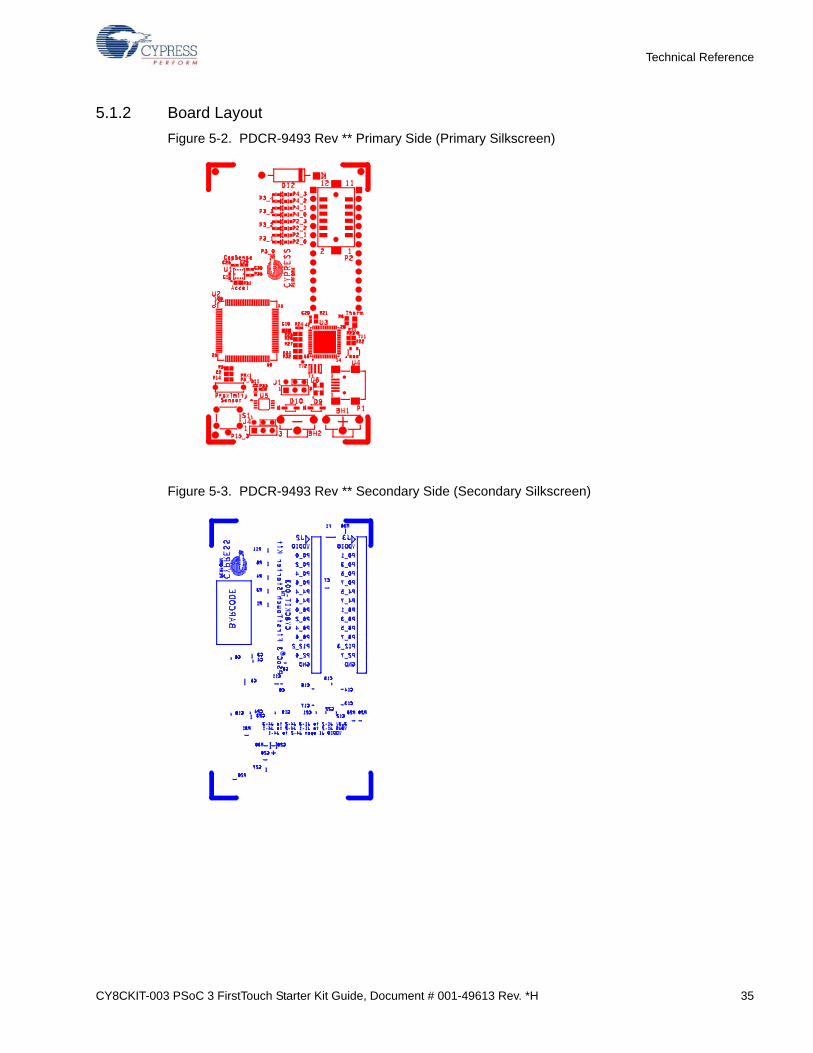
5.1.2 Board Layout
Figure 5-2. PDCR-9493 Rev ** Primary Side (Primary Silkscreen)
Figure 5-3. PDCR-9493 Rev ** Secondary Side (Secondary Silkscreen)
36 CY8CKIT-003 PSoC 3 FirstTouch Starter Kit Guide, Document # 001-49613 Rev. *H
Technical Reference
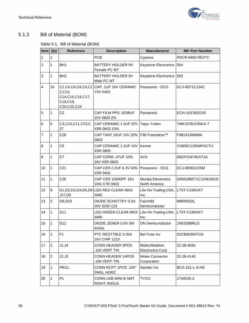
5.1.3 Bill of Material (BOM)
Table 5-1. Bill of Material (BOM)
Item Qty Reference Description Manufacturer Mfr Part Number
1 1 PCB Cypress PDCR-9493 REV*C
2 1 BH1 BATTERY HOLDER 9V Female PC MT
Keystone Electronics 594
3 1 BH2 BATTERY HOLDER 9V Male PC MT
Keystone Electronics 593
4 16 C1,C4,C6,C8,C9,C12,C13, C14,C15,C16,C17,C18,C19, C20,C22,C24
CAP .1UF 16V CERAMIC Y5V 0402
Panasonic - ECG ECJ-0EF1C104Z
5 1 C2 CAP FILM PPS .0039UF 10V 0603 2%
Panasonic ECH-U01392GX5
6 5 C3,C10,C11,C23,C27
CAP CERAMIC 1.0UF 25V X5R 0603 10%
Taiyo Yuden TMK107BJ105KA-T
7 1 C28 CAP TANT 10UF 10V 20% 0603
F98 Frameless™ F981A106MMA
8 1 C5 CAP CERAMIC 1.2UF 10V X5R 0805
Kemet C0805C125K8PACTU
9 1 C7 CAP CERM .47UF 10% 16V X5R 0603
AVX 0603YD474KAT2A
10 1 C21 CAP CER 2.2UF 6.3V 20% X5R 0402
Panasonic - ECG ECJ-0EB0J225M
11 1 C26 CAP CER 10000PF 16V 10% X7R 0603
Murata Electronics North America
GRM188R71C103KA01D
12 8 D1,D2,D3,D4,D5,D6,D7,D8
LED RED CLEAR 0603 SMD
Lite-On Trading USA, Inc.
LTST-C190CKT
13 2 D9,D10 DIODE SCHOTTKY 0.5A 20V SOD-123
Fairchild Semiconductor
MBR0520L
14 1 D11 LED GREEN CLEAR 0603 SMD
Lite-On Trading USA, Inc.
LTST-C190GKT
15 1 D12 DIODE ZENER 5.6V 5W AXIAL
ON Semiconductor 1N5339BRLG
16 1 F1 PTC RESTTBLE 0.35A 16V CHIP 1210
Bel Fuse Inc 0ZCB0035FF2G
17 2 J1,J4 CONN HEADER 3POS .100 VERT TIN
Molex/Waldom Electronics Corp
22-28-4030
18 2 J2,J3 CONN HEADER 14POS .100 VERT TIN
Molex Connector Corporation
22-28-4140
19 1 PRX1 CONN RCPT 1POS .100" SNGL HORZ
Samtec Inc BCS-101-L-S-HE
20 1 P1 CONN USB MINI B SMT RIGHT ANGLE
TYCO 1734035-2
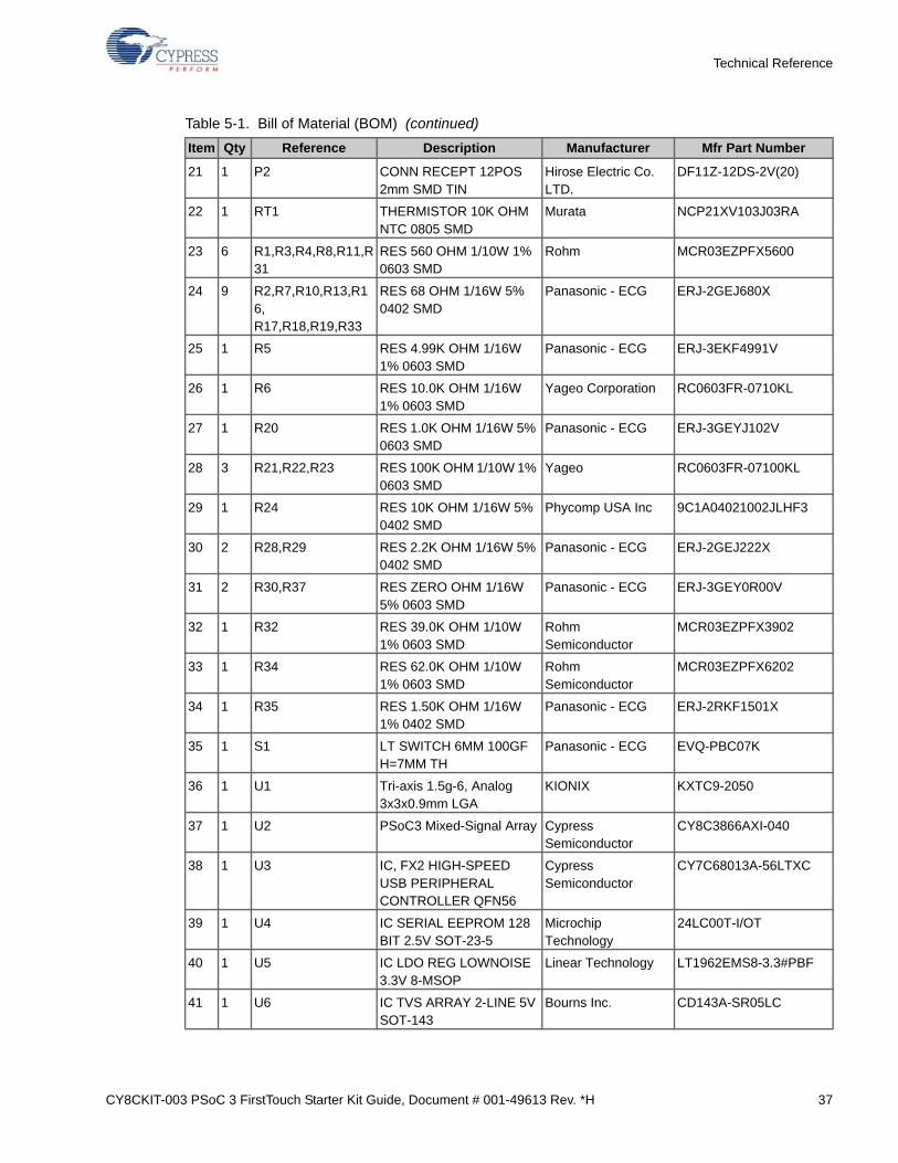
CY8CKIT-003 PSoC 3 FirstTouch Starter Kit Guide, Document # 001-49613 Rev. *H 37
Technical Reference
21 1 P2 CONN RECEPT 12POS 2mm SMD TIN
Hirose Electric Co. LTD.
DF11Z-12DS-2V(20)
22 1 RT1 THERMISTOR 10K OHM NTC 0805 SMD
Murata NCP21XV103J03RA
23 6 R1,R3,R4,R8,R11,R31
RES 560 OHM 1/10W 1% 0603 SMD
Rohm MCR03EZPFX5600
24 9 R2,R7,R10,R13,R16, R17,R18,R19,R33
RES 68 OHM 1/16W 5% 0402 SMD
Panasonic - ECG ERJ-2GEJ680X
25 1 R5 RES 4.99K OHM 1/16W 1% 0603 SMD
Panasonic - ECG ERJ-3EKF4991V
26 1 R6 RES 10.0K OHM 1/16W 1% 0603 SMD
Yageo Corporation RC0603FR-0710KL
27 1 R20 RES 1.0K OHM 1/16W 5% 0603 SMD
Panasonic - ECG ERJ-3GEYJ102V
28 3 R21,R22,R23 RES 100K OHM 1/10W 1% 0603 SMD
Yageo RC0603FR-07100KL
29 1 R24 RES 10K OHM 1/16W 5% 0402 SMD
Phycomp USA Inc 9C1A04021002JLHF3
30 2 R28,R29 RES 2.2K OHM 1/16W 5% 0402 SMD
Panasonic - ECG ERJ-2GEJ222X
31 2 R30,R37 RES ZERO OHM 1/16W 5% 0603 SMD
Panasonic - ECG ERJ-3GEY0R00V
32 1 R32 RES 39.0K OHM 1/10W 1% 0603 SMD
Rohm Semiconductor
MCR03EZPFX3902
33 1 R34 RES 62.0K OHM 1/10W 1% 0603 SMD
Rohm Semiconductor
MCR03EZPFX6202
34 1 R35 RES 1.50K OHM 1/16W 1% 0402 SMD
Panasonic - ECG ERJ-2RKF1501X
35 1 S1 LT SWITCH 6MM 100GF H=7MM TH
Panasonic - ECG EVQ-PBC07K
36 1 U1 Tri-axis 1.5g-6, Analog 3x3x0.9mm LGA
KIONIX KXTC9-2050
37 1 U2 PSoC3 Mixed-Signal Array Cypress Semiconductor
CY8C3866AXI-040
38 1 U3 IC, FX2 HIGH-SPEED USB PERIPHERAL CONTROLLER QFN56
Cypress Semiconductor
CY7C68013A-56LTXC
39 1 U4 IC SERIAL EEPROM 128 BIT 2.5V SOT-23-5
Microchip Technology
24LC00T-I/OT
40 1 U5 IC LDO REG LOWNOISE 3.3V 8-MSOP
Linear Technology LT1962EMS8-3.3#PBF
41 1 U6 IC TVS ARRAY 2-LINE 5V SOT-143
Bourns Inc. CD143A-SR05LC
Table 5-1. Bill of Material (BOM) (continued)
Item Qty Reference Description Manufacturer Mfr Part Number
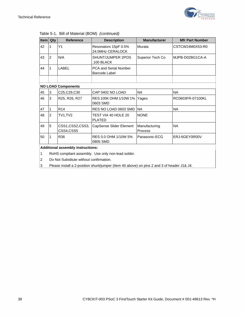
38 CY8CKIT-003 PSoC 3 FirstTouch Starter Kit Guide, Document # 001-49613 Rev. *H
Technical Reference
42 1 Y1 Resonators 15pF 0.5% 24.0MHz CERALOCK
Murata CSTCW24M0X53-R0
43 2 N/A SHUNT/JUMPER 2POS .100 BLACK
Superior Tech Co MJPB-D02BG1CA-A
44 1 LABEL PCA and Serial Number Barcode Label
NO LOAD Components
45 3 C25,C29,C30 CAP 0402 NO LOAD NA NA
46 3 R25, R26, R27 RES 100K OHM 1/10W 1% 0603 SMD
Yageo RC0603FR-07100KL
47 1 R14 RES NO LOAD 0603 SMD NA NA
48 2 TV1,TV2 TEST VIA 40 HOLE 20 PLATED
NONE
49 5 CSS1,CSS2,CSS3,CSS4,CSS5
CapSense Slider Element Manufacturing Process
NA
50 1 R36 RES 0.0 OHM 1/10W 5% 0805 SMD
Panasonic-ECG ERJ-6GEY0R00V
Additional assembly instructions:
1 RoHS compliant assembly. Use only non-lead solder.
2 Do Not Substitute without confirmation.
3 Please install a 2-position shunt/jumper (Item 40 above) on pins 2 and 3 of header J1& J4.
Table 5-1. Bill of Material (BOM) (continued)
Item Qty Reference Description Manufacturer Mfr Part Number

CY8CKIT-003 PSoC 3 FirstTouch Starter Kit Guide, Document # 001-49613 Rev. *H 39
Technical Reference
5.2 PSoC 3 Pin Assignment on PSoC 3 FirstTouch Starter Kit Board
Table 5-2. Pin Assignments
Pin Number Port Number Design Function
1 P2[5] Unused / No connect
2 P2[6] General expansion connector J2 pin 13
3 P2[7] General expansion connector J3 pin 13
4 P12[4] Unused/No Connect
5 P12[5] Unused/No Connect
6 P6[4] General expansion connector (J2) Pin 10
7 P6[5] General expansion connector (J3) Pin 10
8 P6[6] General expansion connector (J2) Pin 11
9 P6[7] General expansion connector (J3) Pin 11
10 Vssb GND
11 Ind Unused/No Connect
12 Vboost GND
13 Vbat GND
14 Vssd GND
15 XRES Reset from FX2LP
16 P5[0] Wireless expansion connector pin 7
17 P5[1] Wireless expansion connector pin 11
18 P5[2] Wireless expansion connector pin 4
19 P5[3] Wireless expansion connector pin 6
20 P1[0] Programming/Debugging Data line
21 P1[1] Programming/Debugging Clock line
22 P1[2] No Connect
23 P1[3] Debugging, Single Wire viewer
24 P1[4] Wireless expansion connector pin 8
25 P1[5] Wireless expansion connector pin 10
26 Vddio1 3.3 V
27 P1[6] CapSense feedback resistor
28 P1[7] Wireless expansion connector pin 12
29 P12[6] Battery low indication input
30 P12[7] No Connect
31 P5[4] CapSense Modulator capacitor
32 P5[5] Thermistor Analog input
33 P5[6] Thermistor Drive Voltage reference
34 P5[7] Proximity Sense antenna connector
35 P15[6] USB/SWD Interface to FX2LP
36 P15[7] USB/SWD Interface to FX2LP
37 Vddd 3.3 V
38 Vssd GND
39 Vccd Input to digital core
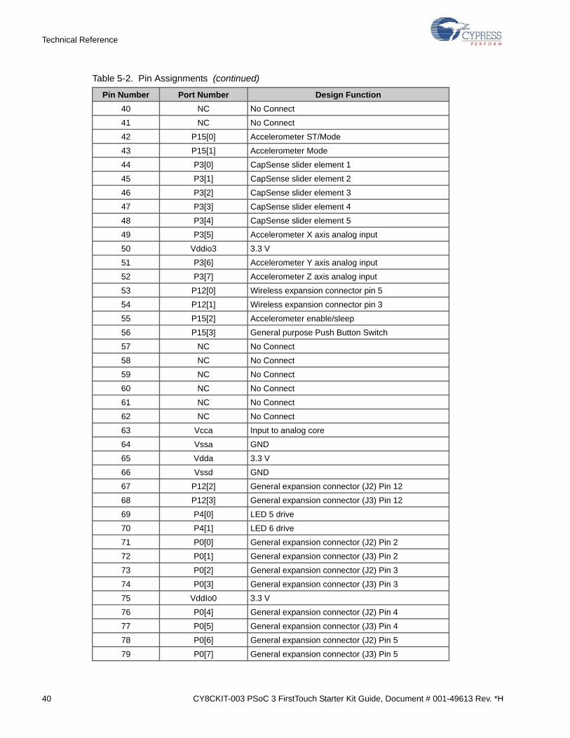
40 CY8CKIT-003 PSoC 3 FirstTouch Starter Kit Guide, Document # 001-49613 Rev. *H
Technical Reference
40 NC No Connect
41 NC No Connect
42 P15[0] Accelerometer ST/Mode
43 P15[1] Accelerometer Mode
44 P3[0] CapSense slider element 1
45 P3[1] CapSense slider element 2
46 P3[2] CapSense slider element 3
47 P3[3] CapSense slider element 4
48 P3[4] CapSense slider element 5
49 P3[5] Accelerometer X axis analog input
50 Vddio3 3.3 V
51 P3[6] Accelerometer Y axis analog input
52 P3[7] Accelerometer Z axis analog input
53 P12[0] Wireless expansion connector pin 5
54 P12[1] Wireless expansion connector pin 3
55 P15[2] Accelerometer enable/sleep
56 P15[3] General purpose Push Button Switch
57 NC No Connect
58 NC No Connect
59 NC No Connect
60 NC No Connect
61 NC No Connect
62 NC No Connect
63 Vcca Input to analog core
64 Vssa GND
65 Vdda 3.3 V
66 Vssd GND
67 P12[2] General expansion connector (J2) Pin 12
68 P12[3] General expansion connector (J3) Pin 12
69 P4[0] LED 5 drive
70 P4[1] LED 6 drive
71 P0[0] General expansion connector (J2) Pin 2
72 P0[1] General expansion connector (J3) Pin 2
73 P0[2] General expansion connector (J2) Pin 3
74 P0[3] General expansion connector (J3) Pin 3
75 VddIo0 3.3 V
76 P0[4] General expansion connector (J2) Pin 4
77 P0[5] General expansion connector (J3) Pin 4
78 P0[6] General expansion connector (J2) Pin 5
79 P0[7] General expansion connector (J3) Pin 5
Table 5-2. Pin Assignments (continued)
Pin Number Port Number Design Function
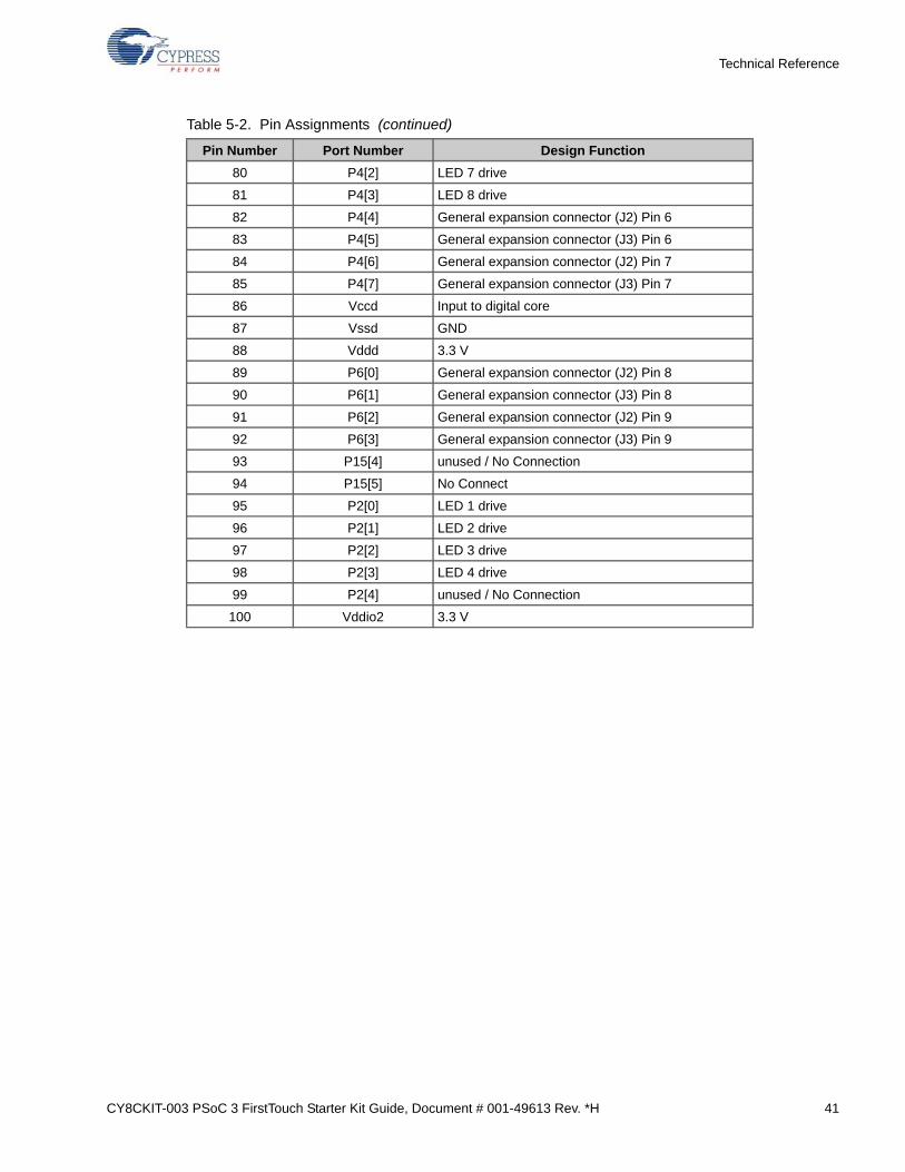
CY8CKIT-003 PSoC 3 FirstTouch Starter Kit Guide, Document # 001-49613 Rev. *H 41
Technical Reference
80 P4[2] LED 7 drive
81 P4[3] LED 8 drive
82 P4[4] General expansion connector (J2) Pin 6
83 P4[5] General expansion connector (J3) Pin 6
84 P4[6] General expansion connector (J2) Pin 7
85 P4[7] General expansion connector (J3) Pin 7
86 Vccd Input to digital core
87 Vssd GND
88 Vddd 3.3 V
89 P6[0] General expansion connector (J2) Pin 8
90 P6[1] General expansion connector (J3) Pin 8
91 P6[2] General expansion connector (J2) Pin 9
92 P6[3] General expansion connector (J3) Pin 9
93 P15[4] unused / No Connection
94 P15[5] No Connect
95 P2[0] LED 1 drive
96 P2[1] LED 2 drive
97 P2[2] LED 3 drive
98 P2[3] LED 4 drive
99 P2[4] unused / No Connection
100 Vddio2 3.3 V
Table 5-2. Pin Assignments (continued)
Pin Number Port Number Design Function

42 CY8CKIT-003 PSoC 3 FirstTouch Starter Kit Guide, Document # 001-49613 Rev. *H
Technical Reference


