
EN 215
Data sheet Thermostatic sensor RAS-C2 with RA-N radiator valve with presetting
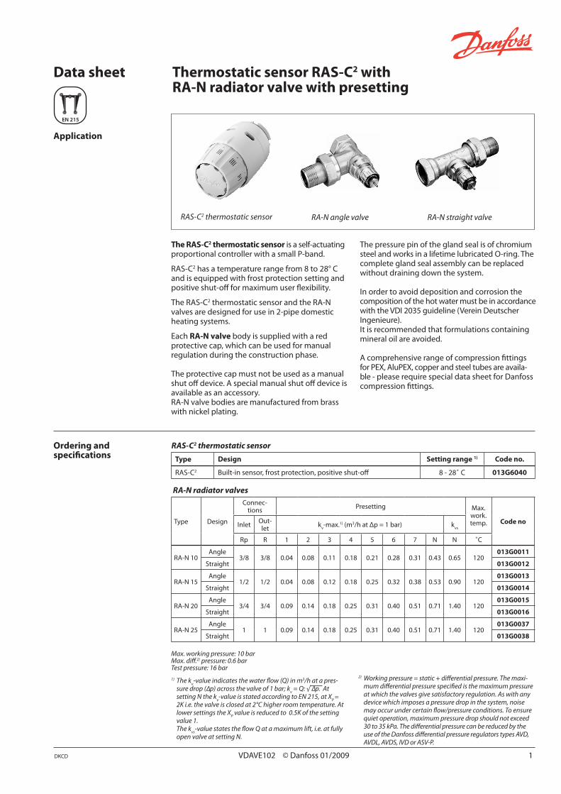
Application
The RAS-C2 thermostatic sensor is a self-actuating proportional controller with a small P-band.
RAS-C2 has a temperature range from 8 to 28° C and is equipped with frost protection setting and positive shut-off for maximum user flexibility.
The RAS-C2 thermostatic sensor and the RA-N valves are designed for use in 2-pipe domestic heating systems.
Each RA-N valve body is supplied with a red protective cap, which can be used for manual regulation during the construction phase.
The protective cap must not be used as a manual shut off device. A special manual shut off device is available as an accessory.RA-N valve bodies are manufactured from brass with nickel plating.
RAS-C2 thermostatic sensor
Ordering andspecifications
RAS-C2 thermostatic sensor
Type Design Setting range 1) Code no.
RAS-C2 Built-in sensor, frost protection, positive shut-off 8 - 28˚ C 013G6040
DKCD VDAVE102 © Danfoss 01/2009 1
RA-N angle valve RA-N straight valve
The pressure pin of the gland seal is of chromium steel and works in a lifetime lubricated O-ring. The complete gland seal assembly can be replaced without draining down the system.
In order to avoid deposition and corrosion the composition of the hot water must be in accordance with the VDI 2035 guideline (Verein Deutscher Ingenieure).It is recommended that formulations containing mineral oil are avoided.
A comprehensive range of compression fittings for PEX, AluPEX, copper and steel tubes are availa-ble - please require special data sheet for Danfoss compression fittings.
RA-N radiator valves
Type Design
Connec-tions Presetting Max.
work. temp. Code noInlet Out-
let kv-max.1) (m3/h at Δp = 1 bar) k
vs
Rp R 1 2 3 4 5 6 7 N N ˚C
RA-N 10Angle
3/8 3/8 0.04 0.08 0.11 0.18 0.21 0.28 0.31 0.43 0.65 120013G0011
Straight 013G0012
RA-N 15Angle
1/2 1/2 0.04 0.08 0.12 0.18 0.25 0.32 0.38 0.53 0.90 120013G0013
Straight 013G0014
RA-N 20Angle
3/4 3/4 0.09 0.14 0.18 0.25 0.31 0.40 0.51 0.71 1.40 120013G0015
Straight 013G0016
RA-N 25Angle
1 1 0.09 0.14 0.18 0.25 0.31 0.40 0.51 0.71 1.40 120013G0037
Straight 013G0038
Max. working pressure: 10 bar Max. diff.2) pressure: 0.6 bar Test pressure: 16 bar
1) The kv-value indicates the water flow (Q) in m3/h at a pres-
sure drop (∆p) across the valve of 1 bar; kv = Q: √ ∆p. At
setting N the kv-value is stated according to EN 215, at X
P =
2K i.e. the valve is closed at 2°C higher room temperature. At lower settings the X
P value is reduced to 0.5K of the setting
value 1. The k
vs-value states the flow Q at a maximum lift, i.e. at fully
open valve at setting N.
2) Working pressure = static + differential pressure. The maxi-mum differential pressure specified is the maximum pressure at which the valves give satisfactory regulation. As with any device which imposes a pressure drop in the system, noise may occur under certain flow/pressure conditions. To ensure quiet operation, maximum pressure drop should not exceed 30 to 35 kPa. The differential pressure can be reduced by the use of the Danfoss differential pressure regulators types AVD, AVDL, AVDS, IVD or ASV-P.

Remove the valve protection cap. Turn the sensor to , then turn the unionnut as much as possible to the right.
Mount the sensor with thescale pointer upwards. Press the sensor firmly onto the valve.
Secure connection by turningthe union nut clock-wise by hand.
Fully tighten the grey union nutusing a pair of parrot nose pliers.
2 VDAVE102 © Danfoss 01/2009 DKCD
Data sheet Thermostatic sensor RAS-C2 with RA-N radiator valve with presetting
Sensor mounting
Accessories Product Dimension For valve body Code no.
Gland seal - All RA-N valves 013G0290
Compression fitting for steel and copper tubes
Rp 3/8 x Ø10 mmRA-N 10
013G4100
Rp 3/8 x Ø12 mm 013G4102
Rp 1/2 x Ø10 mm
RA-N 15
013G4110
Rp 1/2 x Ø12 mm 013G4112
Rp 1/2 x Ø15 mm 013G4115
All accessories comes in boxes of 10 pcs.
1 2
3 4
5 6

5 7 10 20 30 40 50 70 100 200 300 400 500 700 1000
1
2
3
4
56
8
kPa
20
30
40
5060
80
1001
0,8
0,60,5
0,4
0,3
0,2
0,1
0,08
0,060,05
0,04
0,03
0,02
0,01
10
pp
V [l/h]
[ ][bar ]
0,1
0,2
0,3
0,4
0,50,6
0,8
1
2
3
4
56
8
10
p
1 2 3 4 5 6 7 N
107543210,70,50,40,30,2
200,2 0,3 0,4 0,5 0,7 1 2 3 4 5 7 10
kW
kW
t=15 Co
ot=20 C
]mWs[
RA-N 10
t=40 C 0,5o
0,4 0,7 1 2 43 5 7 10 20 30 40 kW
o4321
0,03 0,05 0,07 0,10,02
0,070,03 0,05 0,1
0,070,05 0,1 0,2 0,3
5 7 10 20 30 40 50 70 100 200 300 400 500 700 1000
1
2
3
4
56
8
kPa
20
30
40
5060
80
1001
0,8
0,60,5
0,4
0,3
0,2
0,1
0,08
0,060,05
0,04
0,03
0,02
0,01
10
pp
V [l/h]
[ ][bar ]
0,1
0,2
0,3
0,4
0,50,6
0,8
1
2
3
4
56
8
10
p
1 2 3 4 5 6 7 N
107543210,70,50,40,30,2
200,2 0,3 0,4 0,5 0,7 1 2 3 4 5 7 10
kW
kW
t=15 Co
ot=20 C
]mWs[
RA-N 15
t=40 C 0,5o
0,4 0,7 1 2 43 5 7 10 20 30 40 kW
o4321
0,03 0,05 0,07 0,10,02
0,070,03 0,05 0,1
0,070,05 0,1 0,2 0,3
Alternatively the setting can be read directly in the table "Data and Ordering".
RA-N 10, Rp 3/8 connection
0.720 x 1.16
Sizing example:
Required heat: 0.7 kW
Cooling across radiator: 20° C
Flow throughradiator: Q = = 0.03 m3/h= 0.0083 l/s
Pressure drop across valve: ∆p = 1 mwg
Valve setting: RA-N 10 3
RA-N 15 3
RA-N 20/25 2
kv =
Q (m3/h)
√∆p (bar)
RA-N 15, Rp 1/2 connection
DKCD VDAVE102 © Danfoss 01/2009 3
Data sheet Thermostatic sensor RAS-C2 with RA-N radiator valve with presetting
Capacities

5 7 10 20 30 40 50 70 100 200 300 400 500 700 1000
1
2
3
4
56
8
kPa
20
30
40
5060
80
1001
0,8
0,60,5
0,4
0,3
0,2
0,1
0,08
0,060,05
0,04
0,03
0,02
0,01
10
pp
V [l/h]
[ ][bar ]
0,1
0,2
0,3
0,4
0,50,6
0,8
1
2
3
4
56
8
10
p
1 2 3 4 5 6 7 N
107543210,70,50,40,30,2
200,2 0,3 0,4 0,5 0,7 1 2 3 4 5 7 10
kW
kW
t=15 Co
ot=20 C
]mWs[
RA-N 20
t=40 C 0,5o
0,4 0,7 1 2 43 5 7 10 20 30 40 kW
o4321
0,03 0,05 0,07 0,10,02
0,070,03 0,05 0,1
0,070,05 0,1 0,2 0,3
Note: As with any device which imposes a pressure drop in the system, noise may occur under certain flow/pressure conditions.To ensure quiet operation, maximum pressure drop should not exceed 30-35 kPa (3-3,5 mwg).
RA-N 20/25, Rp 3/4 - R
p 1 connection
Factory setting and one-pipe system
Presettingrange
Reference mark
The presetting values of RA-N valves can be adjusted easily and accurately without the use of tools (factory setting = N):
• Removeprotectivecap/thermostatic sensor • Findreferencemark • Liftandturnsettingringuntiltheaquired presetting aligns with the reference mark.
Presetting can be selected in steps from 1 to 7.
Presetting
At setting N the valve is fully open. This setting can be used as a flushing position, if the system has to be flushed out because of dirt problems.In one-pipe installations, the setting N must be used.
Settings outside 1 to 7 and N should be avoided.
When the thermostatic sensor has been installed, the presetting is protected against unintended regulation.
4 VDAVE102 © Danfoss 01/2009 DKCD
Data sheet Thermostatic sensor RAS-C2 with RA-N radiator valve with presetting

ø50
ø40.5
1376.9 - 83.8
S2
d2
d1
S1
D L3
L4
L 5H
1
H2
H3
D
L2
L1
d2
d1
S1
S2
H2
H1
H3
1 2 3 4 5 6 7
RAS-C2
5 VDAVE102 © Danfoss 01/2009 DKCD
ValveISO 7-1
L1
L2
L3
L4
L5
H1
H2
H3
Arc. flats
D d1
d2
S1
S2
RA-N 10 G 3/8 G 5/8 A R 3/8 50 75 24 49 20 47 50 15 22 27
RA-N 15 G 1/2 G 3/4 A R 1/2 55 82 26 53 23 47 50 15 27 30
Dimensions
RA-N Design
1. Gland seal2. O-Ring3. Pressure pin4. Seal
5. Regulation spring6. Setting dial7. Valve body8. k
v-nozzle
1. Actuator2. Setting dial3. Safety spring4. Bellows
5. Spindle6. Socket7. Union nut
Data sheet Thermostatic sensor RAS-C2 with RA-N radiator valve with presetting


