

DATE: October 25, 2012 TO: Associate Region Engineers – Development Region Design Engineers Operations – Field Services Division Bridge Development – Design Division Design Programs – Design Division FROM: Bradley C. Wieferich Engineer of Design SUBJECT: Design Process and Plan Changes – Phase II The first of a multi-phase implementation of changes to design processes and plan set standards was rolled out in the spring of 2011. Phase I, which is now fully implemented, incorporated new sheet borders, employed the use of MS Word and Excel to create information sheets, and enhanced the way that drawing and sheet numbers are developed. The changes directed by this memo for Phase II are primarily the result of efforts led by the Right of Way Process Improvement (ROW PI) and the Design Deliverables Enhancement Project (DDEP) teams, which are both comprised of department staff and members of the consultant community. Reference Information Documents: MDOT has developed a Reference Information Document (RID) process by which electronic data files such as CADD drawings or survey files, are made available through the e-Proposal website. Contractors may use these non-contractual items prior to bidding on construction projects. In order to facilitate the process of posting RID documents in a uniform manner to the e-Proposal site, maintain uniform ProjectWise file structuring, and create statewide consistency for ease of finding information for future use, file naming conventions have also been established. The following attachments are included for reference:
• Attachment A: e-Proposal RID Process • Attachment B: RID Files and Naming Conventions • Attachment C: Example of RID Index
This guidance for RID is effective for all projects starting with the January 11, 2013, letting.

Page 2 October 25, 2012 Design Plan and Process Changes: Several other changes to the design process are being implemented to enhance deliverables and improve consistency in plan development. The attachments listed below provide detailed guidance for the preparation of plans including true typical sections, design cross sections at development milestones, and Right of Way (ROW) and alignment concepts:
• Attachment D: Plan and Proposal Milestone Naming Conventions • Attachment E: Typical Section Development Guidelines • Attachment F: Design Cross Section Guidelines • Attachment G: Adaptation of Alignment/ROW Concepts • Attachment H: Example Alignment/ROW Sheets
These plan and process changes are effective for all projects with design commencing after November 1, 2012. In the coming months, the Design Services Section will be hosting Design Technology Forums across the state to communicate changes in detail to MDOT design staff and consultant attendees. Updates to the Road Design Manual, to specify process and plan development with the integration of the above requirements are pending. It is understood that not all guidance will be applicable to non-road design projects (i.e. bridge, signals, signing, ITS, etc…). The Design Services Section will meet with these groups individually to discuss what portions shall be implemented. Please ensure that this direction is provided to all project managers in your area. Contact the Design Services Section Manager, Dan Belcher, at 517-335-2182 or ([email protected]), if there are questions. _____Signature on File____ Engineer of Design cc: D. Belcher R. VanDeventer J. Lobbestael C. Youngs L. Strzalka T. VandenBerg M. Shulick H. VerHage

e-Proposal – Reference Information Document (RID) Process Page 1
e-Proposal – Reference Information Documents (RID) Process Beginning 01-11-13, the Reference Information Documents (RID) Process will be a requirement of the e-Proposal Process. Project Managers will be required to turn-in specific reference files at final turn-in, along with the Proposal, Plan Set and supporting documents, to Specs & Estimates. The files we are releasing are for information only. There is a disclaimer on the main e-Proposal sign in page (https://mdotwas1.mdot.state.mi.us/public/eprop/login/) that has been approved by the AG’s office. This disclaimer protects MDOT/consultants from the RID being anything but for information purposes only. The e-Proposal website displays a section for RID files. RID files to be published will include design files, survey deliverable files, and a RID Index Sheet. For a detailed list and naming convention on what to include in the RID, please see the attached file (MDOT RID Files and Naming Conventions.doc). These files are published to the web using a ProjectWise workflow similar to the NTB Inquiry process. The initial RID files will be submitted to Specs & Estimates at final turn-in. Specs & Estimates will review for concurrence with MDOT RID standards. Finance will then publish RID files to the web at the same time the Proposal and Plans are published. Any changes made to these files after this time, due to an Addendum, will be the responsibility of the Project Manager to publish. Each published ‘set’ released after the original publication shall include a revised Index Sheet that includes a brief explanation of the changes made to the files. Adding Initial RID files to RID folder:
1. At the time of final turn-in to Specs & Estimates, drag and drop files into the RID – Change Storage to Michtrans7 located under Region > TSC > JN folder > 6 – Letting Plans and Proposal > RID – Change Storage to Michtrans7. (If you need a RID folder added to your ProjectWise project folder, please send a request to [email protected] )
2. Use the Advanced Wizard to assign appropriate attributes and a Document Type of ‘Reference Information Documents’ to all RID files.
3. DO NOT CHANGE the state to next on these files at this time. Finance will perform the initial publication of RID files to the website at the same time the Proposal and Plans are published.
Adding updated files to RID folder AFTER initial publication: ***This is the responsibility of the Project Manager to publish, not Finance***
1. If updates/changes are needed after initial publication of RID files, copy updated DGN files to the RID – Change Storage to Michtrans7 folder. Be sure to include an updated Index Sheet with explanation of changes.
2. File names shall include date of publication. 3. Change the workflow state of the documents to post updated files to website. Highlight all of the
revised/additional files to post > single right mouse click > select Change State > Next. The state is now e-Proposal RID Published.

RID Files and Naming Conventions Page 1
RID Files and Naming Conventions
This document is a guide as to which project documents shall be released as reference information documents (RID) for bidding purposes, and what format and file naming convention shall apply. To apply to projects for any given job number (XXXXXX): Design Files: (The files listed under Design Files are applicable for plan set projects containing road work. They may not apply to bridge or ITS projects at this time.)
• XXXXXX_Align_date.dgn o DGN file from design that contains all project horizontal roadway alignments. (If
using models or multiple alignment scales, include only one set of the project alignments, preferably the alignments at the scale used for the Alignment/ROW Sheets.)
o Please refer to alignment levels within the Alignments Level Library (mdot_01 workspace) for standard levels that would be used within this reference file.
• XXXXXX_Const_date.dgn
o DGN file from design that contains proposed construction elements.
• XXXXXX_Drain_date.dgn o DGN file from design that contains proposed project drainage. Depending on
the size of the project, and the design preferences of the project team, the information in this file may be included in the XXXXXX_Const_date.dgn.
o Please refer to the proposed drainage levels within the Drainage Level Library (mdot_01 workspace) for standard levels that would be used within this reference file.
• XXXXXX_Parcel_date.dgn*
o DGN file from real estate/design that contains project parcel information. This file should be provided by Real Estate or the Real Estate consultant.
o Please refer to parcel levels within the Boundary Level Library (mdot_01 workspace) for standard levels that would be used within this reference file.
• XXXXXX_Prof_date.dgn or XXXXXX_Prof_roadway_date.dgn
o DGN file(s) from design that contains profile information. o Please refer to profile levels within the Profile Level Library (mdot_01 workspace)
for standard levels that would be used within this reference file.
• XXXXXX_ROW_date.dgn o DGN file from design that contains existing and proposed ROW information. o Please refer to boundary levels within the Boundary Level Library (mdot_01
workspace) for standard levels that would be used within this reference file.
• XXXXXX_Topo_date.dgn o DGN file from design that contains existing topographic project data. o This file includes topographic project data from surveys, and any existing items
moved to a removal, adjust, or relocate level.

RID Files and Naming Conventions Page 2
• XXXXXX_Utility_date.dgn o DGN file from design that contains underground and overhead utility lines.
Typically this information is provided by the utility companies during the life of the project and may be in approximate locations.
o Please refer to underground and overhead utility line levels within the Utilities Level Library (mdot_01 workspace) for standard levels that would be used within this reference file.
• XXXXXX_PrModel_date.dgn (if applicable) o Copy of the proposed final surface model from design, generated with Roadway
Designer, that includes the 3D line strings for critical proposed final surface features (i.e. proposed edge of pavement, proposed back of curb, etc.).
o For directions on creating this GEOPAK file, please see the GEOPAK Road Design Training Manual.
• XXXXXX_PrTriangle_date.dgn (if applicable)
o File from design that contains the proposed surface triangle file for the project. o For directions on creating this GEOPAK file, please see the GEOPAK Road
Design Training Manual.
• XXXXXX_LandXML_Geometry_date.xml (if applicable) o File from design that shall include all alignments (horizontal and vertical). o For directions on creating this GEOPAK output file, please see the GEOPAK
Road Design Training Manual.
Survey Files:
• XXXXXX_Survey_2D_date.dgn and XXXXXX_Survey_3D_date.dgn (if applicable) o Copies of the original survey topo files delivered for the project design. o These files should be in their original state and should not contain any changes
from design.
• XXXXXX_ExTriangle_date.dgn o Copy of the original survey existing surface triangle file delivered for the project
design. o This file should be in its original state and should not contain any changes from
design.
• XXXXXX_ExDTM_date.tin or XXXXXX_ExDTM_date.dat (if applicable) o Copy of the original survey existing tin (current standard survey deliverable) or
dat (previous standard survey deliverable) GEOPAK file delivered for the project design.
o This file should be in its original state and should not contain any changes from design.
• XXXXXX_ControlPts_date.txt
o Copy of the original survey control points file delivered for the project. o This file should be in its original state and should not contain any changes from
design.

RID Files and Naming Conventions Page 3
Miscellaneous Files: • XXXXXX_Xsec_roadway_date.pdf
o Cross-section files from design placed on cross-section grids. o Add station range to the file name if necessary. (XXXXXX_XSEC_roadway_310-
320.pdf) o Please refer to cross-section levels within the XS Level Library (mdot_01
workspace) for standard levels that would be used within this reference file.
* - This file is a new reference file for the ROW PI pilot projects. It is not a reference file that all projects may currently have. More information on the implementation of this reference file will be forthcoming. Please Note:
1. For date, label with the date of original project turn in to the Specifications & Estimates Unit. Or, in the case of file updates, please use the date of the addendum. The date will be important for tracking changes that have been made during advertisement. The process for adding updated files to e-Proposal after advertisement will be the same process as the MDOT Notice to Bidder Inquiry process. Add updated files with the appropriate date to the RID area in ProjectWise, include an updated Index, and change the state on the additional files. (MDOT Project Managers - See RID Process directions or contact MDOT’s Design Services Section for more information.)
2. If design files were created an older MDOT workspace than MDOT’s current workspace (mdot_01), please provide the design files with the appropriate levels from the workspace used to design the project.
3. Files labeled to deliver “(if applicable)” are not currently a requirement for plan turn in but the inclusion of them is encouraged if the files were created. Whether or not the files exists may be dependent on which MDOT workspace the project is completed in, the survey deliverables for the project, and/or whether GEOPAK Roadway Designer (mdot_01 MicroStation workspace) was employed for the design. Further deliverable requirements will be forthcoming. If the project has the listed file available, or the listed file has been created as part of the design process, it shall be included as part of the RID. For any questions regarding this matter, please contact MDOT’s Design Services Section.

Example of RID Index
Example of RID Index Page 1
RID – I-99 from Main Street to M-00 Contract ID: 99999-123456
Index of Reference Information Documents Design Files:
123456_Align_10-5-2012.dgn: road alignment file
123456_Const_10-5-2012.dgn: proposed roadway design base file
123456_Drain_10-5-2012.dgn: proposed drainage file (plan view)
123456_Prof_10-5-2012.dgn: road centerline elevation design file, includes drainage structures
123456_ROW_10-5-2012.dgn: existing and proposed right-of-way file
123456_Topo_10-5-2012.dgn: existing road file including removal items
123456_Utility_10-5-2012.dgn: existing underground and overhead utilities file
123456_PrModel_10-5-2012.dgn: proposed model of final surface including 3D line strings
123456_PrTriangle_10-5-2012.dgn: 3D file containing proposed surface triangles
123456_LandXML_Geometry_2012.xml: xml file containing all horizontal and vertical alignments
Survey Files:
123456_Survey_2D_10-5-2012.dgn: original survey topo file as delivered to design
123456_ExTriangle_10-5-2012.dgn: original survey existing surface triangle file as delivered to design
123456_ControlPts_10-5-2012.dgn: original survey control points as delivered to design
Miscellaneous Files:
123456_Xsec_M43_10-5-2012.pdf: pdf document of M-43 design cross-sections

Plan and Proposal Milestone File Naming Convention Page 1
Plan and Proposal Milestone File Naming Convention
For the given job number XXXXXX:
Base Plans:
XXXXXX _Road_Base.pdf
XXXXXX _Bridge_Base.pdf
XXXXXX _Proposal_Base.pdf (if applicable)
Preliminary Plans:
XXXXXX _Road_Prelim.pdf
XXXXXX _Bridge_Prelim.pdf
XXXXXX _Proposal_Prelim.pdf (if applicable)
Marked Final ROW:
XXXXXX _Road_MFROW.pdf
OEC Plans:
XXXXXX _Road_OEC.pdf
XXXXXX _Bridge_OEC.pdf
XXXXXX _Proposal_OEC.pdf
Final Plan Turn In:
XXXXXX _Road.pdf
XXXXXX _Bridge.pdf
XXXXXX _Proposal.pdf
The maximum pdf file size for any given plan set submittal is 30 MB. If more than one set is
needed per package due to size, number sets sequentially. For example:
XXXXXX _Road_OEC1.pdf
XXXXXX _Road_OEC2.pdf

FINAL ROW PLAN REVISIONS (SUBMITTAL DATE )
NO SCALE DATE: CS: PLAN GUIDELINES DRAWING SHEET
NO. DATE AUTH DESCRIPTION NO. DATE AUTH DESCRIPTION DESIGN UNIT: JN: TYPICAL SECTIONS SECT 1
FILE: TSC:
TYPICAL SECTIONS - GENERAL ITEMS: G1. All work items on the typical cross sections are to be in capital letters. Use the proper fonts, sizes,
levels, weights, etc. Proper pay items on the typical sections are to match the MDOT standard pay items and/or the specifications book.
G2. Whole words should be used when possible, but abbreviations are acceptable. The following are some standard abbreviations: PAVT – Pavement SHLD – Shoulder CP – Crown Point PT – Point AGG – Aggregate OGDC – Open Graded Drainage Course POR – Point of Rotation PG – Plan Grade CONC – Concrete
G3. Label the existing and proposed lanes and shoulders. If the dimension is a whole number do not label with a decimal. Do not show grade differentials (-0.24’) and or circles at break points. For horizontal dimensions use decimals not feet and inches. Vertical dimensions are typically in inches.
G4. Always show existing and proposed plan grade, crown point and point of rotation locations. G5. Typical sections are a general representation; the intent is not to show every scenario. Utilize
miscellaneous details or side typical sections to illustrate unique construction locations. G6. Label the typical sections with general varying widths for the station range of the typical. Exact station
ranges and widths of tapers, transitions, gores, etc are to be shown on the construction sheets. G7. Existing typical cross sections should be developed as complete as possible from old plans, pavement
cores, soil borings and field inspections. All layers of all materials should be shown including subbase and aggregate if known. It is critical to identify the type and thickness of concrete pavement, HMA thickness, existing underdrains, or other items that can affect the bid price.
G8. The following items may require separate half section typical or details and shall be used as needed: Guardrail sections Shoulder sections Crossroads Fill/Cut sections Curb and gutter sections Turn lanes Lane widening Ramps Crossovers Retaining Walls
G9. Government lines shall not be shown on the typical sections.
TYPICAL SECTIONS: 1. Existing typical sections will be located before the proposed typical sections and will be grouped
together. Existing and proposed typical sections will not be on the same sheet. 2. The removal type lines and the ‘GRADE TO THIS LINE’ call will address how removal items are paid
for. Items that are not included in the removal type lines or the ‘GADE TO THIS LINE’ call will be called out to be removed separately (example: guardrail or curb and gutter when paid for separately). If the items being removed are covered by the specifications book the pay item name is not required on the typical section. The ‘GRADE TO THIS LINE’ call is only shown on the existing typical section and should match the bottom line of the coinciding proposed typical section.
3. Label all existing materials. Clarity on where this information originated from may be added by notes if needed.
4. Removal items on the existing typical sections are not to be crosshatched. 5. Only show alignments (LEGAL ALI OR NON-LEGAL ALI) that are being used to construct the
roadways. Alignment labels shall match the labels in the plan set. 6. Existing and proposed ROW is labeled from ROW line to ROW line, it is not tied to any of the
alignments. Identify if it is limited access (LA) ROW. 7. Include station equations that are within the typical section station range. If multiple equations exist
within the station range they should be shown in a separate box. 8. Multiple station ranges can be used on the same typical section. 9. Side slopes that vary through the station limits shall be labeled as “SLOPE VARIES” or “SLOPES
VARY” in the type line or “VARIES” with an arrow instead of specifying a slope. The specific slopes will typically be detailed on the profile sheets. If there are no profile sheets this information can be detailed on the typical.
10. When the pay item “SLOPE RESTORATION, TYPE _” is used, the type can be left blank. 11. The longitudinal pavement joint type labels shall not be shown on the typical sections. Pavement joints
will only be shown as a vertical line along with a horizontal lane tie. 12. Proposed ditches that vary within the station range shall be labeled as “DITCH SLOPES, BOTTOM
WIDTH AND DEPTH VARY”. The specific slopes, bottom width and depth will typically be detailed on the profile sheets. If there are no profile sheets this information can be detailed on the typical.
13. The pavement cross slope on a superelevated typical section will be labeled as ‘RATE OF SUPER’ when the typical section includes the crown-runout and transition or if multiple curves are within the typical station ranges. If the superelevated typical section is in full super for the entire station range then the specific percent super can be shown.
14. Varying shoulder slopes on super elevated typical sections will be labeled with an asterisk (*). Shoulder slopes that are in the same direction that the pavement is superelevated will include a slope arrow. Slopes on the high side that slope in the opposite direction of the pavement super will not have an arrow.
15. The HMA application table should appear only on the first proposed typical sheet that has an HMA pavement section. This table should be placed in the lower left corner of the typical sheet.
Attachment E - Typical Section Examples Page 1

LIMITS OF PAVT, REM
LEGAL ALI
M-11 (28TH STREET)
2% 2%2% 2%2% 2%
1.5%1.5%1.5% 1.5% 1.5%
LIMITS OF HMA SURFACE, REM
LIMITS OF PAVT, REM
NON-LEGAL ALI
NB M-53
LIMITS OF HMA SURFACE, REM
LIMITS OF PAVT, REM
NON-LEGAL ALI
SB M-53
M-11 (28TH ST) STA 70+00.00 TO STA 140+00.00
SECTION APPLIES TO:
2.5’2.5’
EXCAVATION, EARTH
PAID FOR AS
GRADE TO THIS LINE
EXCAVATION, EARTH
PAID FOR AS
GRADE TO THIS LINE
(TYP)
EX GROUND
EX 4" UNDERDRAIN (TYP)
EX 1.5" HMA
EX 4" OGDC EX 10" SUBBASE
EX 1.5" HMA EX 1.5" HMA
EX 4" UNDERDRAIN (TYP)EX 10" SUBBASE EX 4" OGDC
EX CURB AND GUTTER (TYP)
EB LANE
EX 12’
EB LANE
EX 12’
LEFT TURN LANE
EX 12’
WB LANE
EX 12’
WB LANE
EX 12’
EX CURB AND GUTTER (TYP)
(TYP)
EX GROUND
EXCAVATION, EARTH
PAID FOR AS
GRADE TO THIS LINE
5’
7’
2.5’
SB LANE
EX 12’
SB LANE
EX 12’
SB LANE
EX 12’
LEFT TURN LANE
EX 0’-12’
2.5’
EX ROW VARIES (230’ MAX, 150’ MIN)
5.5’
2.5’
RIGHT TURN LANE
EX 0’-12’
NB LANE
EX 12’
NB LANE
EX 12’
NB LANE
EX 12’
LEFT TURN LANE
EX 0’-12’
2.5’
EXCAVATION, EARTH
PAID FOR AS
GRADE TO THIS LINE
1.5% 1.5% 1.5% 1.5%
EXCAVATION, EARTH
PAID FOR AS
GRADE TO THIS LINE
LINE SHORTENS 1.06’
STA 527+47.16 AH
STA 527+46.10 BK=
STA EQUATION
NB M-53 NON-LEGAL ALI
108’
SB M-53 STA 550+00.00 TO STA 600+00.00
SB M-53 STA 520+00.00 TO STA 529+47.00
SECTION APPLIES TO:
NB M-53 STA 550+00.00 TO STA 600+00.00
NB M-53 STA 520+00.00 TO STA 529+47.00
SECTION APPLIES TO:
1
2
22
2
2
2
2
2
3 3
3
2
4 4
4
5 5
5
6
6
7
88
G1
G2
G4
G4
G3
G1 2
2
G7
G7
G1
EX CURB AND GUTTER EX 8" HMA
6’
EX 12" SUBBASE
EX 90’ ROW
PROP ROW
EX CURB AND GUTTER ˜
EX SIDEWALK ˜˜ EX SIDEWALK
EX SIDEWALK ˜
EXISTING NORMAL SECTION EXISTING NORMAL SECTION
EXISTING NORMAL SECTION
CONC PAVT
EX 12" NONREINF
CONC PAVT
EX 10" REINF
CONC PAVT
EX 10" REINF
& CROWN POINT
EX PLAN GRADE
& CROWN POINT
EX PLAN GRADE
& CROWN POINT
EX PLAN GRADE
CS:
JN:
TSC:
DATE:
FILE:
DESIGN UNIT:DESCRIPTIONAUTH
DRAWING SHEET
FINAL ROW PLAN REVISIONS ( SUBMITTAL DATE: )
0
0 16
16
VERT. (FT)
HORZ. (FT)
DESCRIPTIONAUTH
SECT 1
Michigan Department of Transportation
DATE NO. DATENO.
EXISTING TYPICAL SECTIONS
EXTYP
001
Attachment E - Typical Section Examples Page 2

SHOULDER
1.5% 1.5% 4%4%
LIMITS OF HMA SURFACE, REM
LIMITS OF PAVT, REM
NON-LEGAL ALI
EB I-196
EXCAVATION, EARTH
PAID FOR AS
GRADE TO THIS LINE
SHOULDERSHOULDER
LIMITS OF PAVT, REM
LIMITS OF HMA SURFACE, REM
NON-LEGAL ALI
WB I-196
4% 1.5% 1.5% 4%
EXCAVATION, EARTH
PAID FOR AS
GRADE TO THIS LINE
SHOULDER SHOULDER
1.5% 1.5% 4%4%
PAVED
EX 6’
EX 4" AGG BASE EX 10" SUBBASE
EX 3" HMA
(TYP)
EX GROUND
EX 7.5" AGG BASE (TYP)
SHOULDER
EX 8’
WB LANE
EX 12’
WB LANE
EX 12’
SHOULDER
EX 10’
PAVED
EX 9’
PAVED
EX 6’
EX 7.5" AGG BASE (TYP)
EX 4.5" HMA (TYP)
EX 3" HMA
EX 4" AGG BASEEX 10" SUBBASE
SHOULDER
EX 8’
EB LANE
EX 12’
WB LANE
EX 12’
SHOULDER
EX 8’
EX 4" AGG BASE EX 10" SUBBASEEX 7.5" AGG BASE (TYP)
EX AGG SHOULDER (TYP)
LIMITS OF PROFILE
LEGAL ALI
M-89
EX 4.5" HMA
(TYP)
EX GROUND
PAVED
EX 3’
PAVED
EX 3’
(2" AT CROWN PT, 2% TO EOM)
COLD MILLING HMA SURFACE
EX 4" AGG SHOULDER (TYP) EX 4" AGG SHOULDER (TYP)
93’
COLD MILLING HMA SURFACE (4% SLOPE)COLD MILLING HMA SURFACE (4% SLOPE)
(TYP)
EX 4.5" HMA
PAVED SHOULDER
EX 10’
EB LANE
EX 12’
EB LANE
EX 12’
SHOULDER
EX 8’
1
2
2
22
2
3
3
3
44
4
5
5 5
6
6
G1
G1
G2G2
G4
G4
2
2
G1
2
2
G3
G7
G3
EXISTING NORMAL SECTION EXISTING NORMAL SECTION
EXISTING NORMAL SECTION
WB I-196 STA 1279+41.00 TO STA 1280+70.00
SECTION APPLIES TO:
EB I-196 STA 1277+80.00 TO STA 1280+70.00
SECTION APPLIES TO:
M-89 STA 100+00.00 TO STA 200+00.00
SECTION APPLIES TO:
EX 100’ ROW
EX 300’ LA ROW
EX GUARDRAIL ˜
(2.75" AT EOM, 5’ AT 4%)
LIMITS OF TRENCHING
(2.75" AT EOM, 5’ AT 4%)
LIMITS OF TRENCHING
CONC PAVT
EX 9" NONREINF
CONC PAVT
EX 9" NONREINF
CONC PAVT
EX 9" NONREINF
EX PG & CP
EX CROWN POINT EX PLAN GRADE EX PLAN GRADE EX CROWN POINT
CS:
JN:
TSC:
DATE:
FILE:
DESIGN UNIT:DESCRIPTIONAUTH
DRAWING SHEET
FINAL ROW PLAN REVISIONS ( SUBMITTAL DATE: )
0
0 16
16
VERT. (FT)
HORZ. (FT)
DESCRIPTIONAUTH
SECT 1
Michigan Department of Transportation
DATE NO. DATENO.
EXISTING TYPICAL SECTIONS
EXTYP
002
Attachment E - Typical Section Examples Page 3

8.5’ 5’
2’
(TYP)
CONC, DET F3
CURB AND GUTTER,
EB LANE
PROP 12’
EB LANE
PROP 12’
LEFT TURN
PROP 12’
WB LANE
PROP 12’
WB LANE
PROP 12’
LANE
2’
(AS SHOWN ON PLANS)
SIDEWALK, CONC, 4 INCH
SUBBASE, CIPSUBBASE, CIP
M-11 (28TH ST) STA 70+00.00 TO STA 73+00.00
SECTION APPLIES TO:
2% 2%2%2%2%
2% 2%
1:1
1:1
LEGAL ALI
M-11 (28TH STREET)
EX 90’ ROW
(TYP)
6’
2%VARIES
(TYP)
EX GROUND
(TYP)
EX GROUND
6%
SEPARATOR
GEOTEXTILE,6 INCH
OPEN GRADED DR CSE,6 INCH (TYP)
OPEN-GRADED,
UNDERDRAIN, PIPE,
LEFT TURN
PROP 0’-12’
SB LANE
PROP 12’
SB LANE
PROP 12’
SB LANE
PROP 12’
LANE
2.5’ 2.5’
5’ VARIES
NON-LEGAL ALI
SB M-53
108’
RIGHT TURN
PROP 0’-12’
NB LANE
PROP 12’
NB LANE
PROP 12’
NB LANE
PROP 12’
LEFT TURN
PROP 0’-12’
LANE LANE
NON-LEGAL ALI
NB M-53
2.5’ 2.5’
6’
1’
(TYP)
CONC, DET F6
CURB AND GUTTER,
SUBBASE, CIP
6 INCH
AGGREGATE BASE,
(AS SHOWN ON PLANS)
SIDEWALK, CONC, 4 INCH
SUBBASE, CIP
2% 2% 2% 2%
2%2%
VARIES2%
1:1
1:1
1:1 1
:1
5E3
4E3
3E3
6’ 6’
2%2%2% 2% 2%
2%2%
6 INCH
AGGREGATE BASE, SUBBASE, CIP
6 INCH (TYP)
UNDERDRAIN, SUBBASE,
SIDEWALK, CONC, 4 INCH
6 INCH (TYP)
UNDERDRAIN, SUBBASE,
EX ROW VARIES (230’ MAX, 150’ MIN)
CONC, DET F6 (TYP)
CURB AND GUTTER,5E3
4E3
3E3
2%
ITEM
550
220
220
REMARKS
64-28
64-28
58-22
TOP COURSE AWI=260
LEVELING COURSE
BASE COURSE
HMA APPLICATION ESTIMATE
IDENT NO. PERFORMANCE GRADE
HMA, 5E3
HMA, 4E3
HMA, 3E3
5E3
4E3
3E3
*FOR INFORMATION ONLY
0.05-0.15 GAL* BOND COAT
(TYP)
EMBANKMENT, CIP
SUBBASE, CIP
9 INCH
CONC PAVT, NONREINF,
(TYP)
1’
(TYP)
1’
(TYP)
1’
12"
12"
12"
(TYP)
1.25’
(TYP)
1.25’
(TYP)
1’
HMA-AHMA-AHMA-A
HMA-A HMA APPROACH 990 64-28
HP HAND PATCHING 330 64-22
4"
4"
4"
LINE SHORTENS 1.06’
STA 527+47.16 AH
STA 527+46.10 BK=
STA EQUATION
NB M-53 NON-LEGAL ALI
PROP CROWN PT PROP PLAN GRADE
2%
SLOPES VARY
RATE LBS PER SYD
6
6
5
55
9
10
9
9
7
G3
G3
G2
G2
G4
G4
G6
G1 G1
G1
11
15
PROP ROW
SB M-53 STA 520+00.00 TO STA 524+50.00
SECTION APPLIES TO:
NB M-53 STA 520+00.00 TO STA 524+50.00
SECTION APPLIES TO:
550 LB/SYD HMA, 3E3 - BASE COURSE (PG 58-22)
220 LB/SYD HMA, 4E3 - LEVELING COURSE
220 LB/SYD HMA, 5E3 - TOP COURSE AWI=260
TURN LANES
HMA, 4E3
VARIES
4’
VARIES
TYPE _ (TYP)
SLOPE RESTORATION,
PERFORMANCE
TURF ESTABLISHMENT,
PROPOSED NORMAL SECTION PROPOSED NORMAL SECTION
PROPOSED NORMAL SECTION
PROP PG & CP PROP PG & CP
CS:
JN:
TSC:
DATE:
FILE:
DESIGN UNIT:DESCRIPTIONAUTH
DRAWING SHEET
FINAL ROW PLAN REVISIONS ( SUBMITTAL DATE: )
0
0 16
16
VERT. (FT)
HORZ. (FT)
DESCRIPTIONAUTH
SECT 1
Michigan Department of Transportation
DATE NO. DATENO.
PROPOSED TYPICAL SECTIONS
PRTYP
001
Attachment E - Typical Section Examples Page 4

SHOULDER
PAVED
10’
SHOULDER
6 INCH
OPEN-GRADED DR CSE,
(TYP)
OPEN-GRADED, 6 INCH
UNDERDRAIN, PIPE,
2% 2% 4%4% 2% 2% 4%VARIES
(TYP)
OPEN-GRADED, 6 INCH
UNDERDRAIN, PIPE,
6 INCH
OPEN-GRADED DR CSE,
SUBBASE, CIP EX SUBBASE
EX SUBBASE
SHOULDER
PAVED
7’
SHOULDER
94’
NON-LEGAL ALI
NB I-196
NON-LEGAL ALI
SB I-196
(TYP)
EX GROUND
EMBANKMENT, CIPEMBANKMENT, CIP
2% 2%2%2%2% 2%2%
2%
NB I-196 STA 1696+86.00 TO STA 1703+00.00
NB I-196 STA 1691+00.00 TO STA 1700+00.00
SECTION APPLIES TO:
109TH AVE RAMP A STA 1693+44.00 TO STA 1694+13.00
SB I-196 STA 1693+40.00 TO STA 1694+11.00
SECTION APPLIES TO:
NON-LEGAL ALI
RAMP A
109TH AVE
SHOULDER SHOULDER
PAVED
10’
94’
NON-LEGAL ALI
NB I-196
NON-LEGAL ALI
SB I-196
SUBBASE, CIP
2%
SHOULDER
PAVED
10’
SHOULDER
(TYP)
EX GROUND
NB I-196 STA 1647+95.00 TO STA 1653+60.00
NB I-196 STA 1642+00.00 TO STA 1647+63.00
SECTION APPLIES TO:
NB I-196 STA 1647+95.00 TO STA 1653+60.00
NB I-196 STA 1642+00.00 TO STA 1647+63.00
SECTION APPLIES TO:
PAVED
4’ 2’2’
PAVED
4’
PAVED
4’
PAVED
4’2’ 2’
(TYP)
2’(TYP)
1’
12" SUBBASE, CIP
12"
12"
(TYP)
1’
(TYP)
1’
(TYP)
2’
6 INCH (TYP)
OPEN-GRADED,
UNDERDRAIN, PIPE,
6 INCH
OPEN-GRADED DR CSE,
(TYP)
2’
*
* * **
SUPERRATE OF
GRADE
PROP PLAN
GRADE
PROP PLAN
SUPERRATE OF
SUPER
RATE OF
SUPER
RATE OF
SUPER
RATE OFSUPER
RATE OF
10 1/2 INCH
NONREINF,
CONC PAVT, MISC,
10 1/2 INCH
CONC PAVT, NONREINF,
10 1/2 INCH
CONC PAVT, NONREINF,
10 1/2 INCH
CONC PAVT, NONREINF,
FULL SUPER SEE STANDARD PLAN R-107 SERIES
* FOR SHOULDER SLOPES IN SUPER TRANSITION AND
AND DEPTH VARY
DITCH SLOPES, BOTTOM WIDTH
SHOULDER
PROP 8’
RAMP LANE
PROP 16’
GORE
PROP 2’-22’
SB LANE
PROP 12’
SB LANE
PROP 12’
SHOULDER
PROP 8’
SLOPE VARIES
AND DEPTH VARY
DITCH SLOPES, BOTT0M WIDTH
SHOULDER
PROP 11’
NB LANE
PROP 12’
NB LANE
PROP 12’
SHOULDER
PROP 8’
SLOPE VARIES
SLOPE VARIES
SHOULDER
PROP 11’
NB LANE
PROP 12’
NB LANE
PROP 12’
SHOULDER
PROP 8’
DITCH SLOPES, BOTTOM WIDTH AND DEPTH VARY
SHOULDER
PROP 8’
SB LANE
PROP 12’
SB LANE
PROP 12’
SHOULDER
PROP 11’
SLOPE VARIES
TYPE _ (TYP)
SLOPE RESTORATION,
TYPE _ (TYP)
SLOPE RESTORATION,
TYPE _ (TYP)
SLOPE RESTORATION,
GEOTEXTILE SEPARATOR
GEOTEXTILE SEPARATOR
GEOTEXTILE SEPARATOR
SUPER
RATE OF
6
6
55
55
5
9 9
99
12 12
12
G3
G3
G6
10
10
10
10
14
14
141414
1413
13
13
G4
G4G4
G4
G1
G1
G1
G2
8
1111
11
11
PROP CROWN PT
PROP CROWN PT
2%
SUBBASE, CIP
6 INCH (TYP)
OPEN-GRADED,
UNDERDRAIN, PIPE,
(TYP)
2’
6 INCH
OPEN-GRADED DR CSE,
10 1/2 INCH
CONC PAVT, NONREINF,
12" SUPER
RATE OF(TYP)
1’
GEOTEXTILE SEPARATOR
G1
*14
*14
PROPOSED NORMAL SECTION PROPOSED NORMAL SECTION
PROPOSED SUPERELEVATED SECTION PROPOSED SUPERELEVATED SECTION
EX 300’ LA ROW
EX 300’ LA ROW
(TYP)
SHOULDER, CL II, 6 INCH
CONC (10 1/2" TYP)
SHOULDER, NONREINF
(TYP)
SHOULDER, CL II, 6 INCH
CONC (10 1/2" TYP)
SHOULDER, NONREINF
CONC (10 1/2" TYP)
SHOULDER, NONREINF
(TYP)
SHOULDER, CL II, 6 INCH
CONC (10 1/2" TYP)
SHOULDER, NONREINF
(TYP)
SHOULDER, CL II, 6 INCH
TL-4, 1:6 SLOPE
CABLE BARRIER, HIGH TENSION,
TYPE (TYP)
SLOPE RESTORATION,
1
1
1
SHOULDER IS NOT REQUIRED
THE UNDERDRAIN UNDER THE HIGH SIDE
WHEN ALL LANES ARE IN FULL SUPERELEVATION
PROP PG & POR PROP PG & POR
PROP PG & POR
CS:
JN:
TSC:
DATE:
FILE:
DESIGN UNIT:DESCRIPTIONAUTH
DRAWING SHEET
FINAL ROW PLAN REVISIONS ( SUBMITTAL DATE: )
0
0 16
16
VERT. (FT)
HORZ. (FT)
DESCRIPTIONAUTH
SECT 1
Michigan Department of Transportation
DATE NO. DATENO.
PROPOSED TYPICAL SECTIONS
PRTYP
002
Attachment E - Typical Section Examples Page 5

EX 4" AGG BASE EX 10" SUBBASE
LEGAL ALI
M-89
(TYP)
EX GROUND
EX HMA
PROP CROWN PT
PAVED
7’
PAVED
7’
SHOULDER SHOULDER
4% 2% 4%
3E3
4E3
EX AGG BASE (TYP)
(TYP)
1’
(TYP)
EMBANKMENT, CIP
& PT OF ROTATION
PROP PLAN GRADE
SUPER
RATE OF*
*
SHOULDER
PAVED
PROP 4’
SHOULDER
SUPER
RATE OF
NONREINF, 9 INCH
CONC PAVT, MISC,
16 INCH
OPEN-GRADED DR CSE, OPEN-GRADED, 6 INCH
UNDERDRAIN, PIPE,
2’2%
2’
EX LA ROW VARIES
(TYP)
EX GROUND
(TYP)
EMBANKMENT, CIP
(9" TYP)
SHOULDER, NONREINF CONC
SLOPE VARIES
SHOULDER
PROP 8’
WB LANE
PROP 12’
EB LANE
PROP 12’
SHOULDER
PROP 8’
SLOPE VARIES
TYPE _ (TYP)
SLOPE RESTORATION,
2%
AND DEPTH VARY
DITCH SLOPES, BOTTTM WIDTH
SHOULDER
PROP 8’
RAMP LANE
PROP 16’
SHOULDER
PROP 6’
SLOPE VARIES
FULL SUPER SEE STANDARD PLAN R-107 SERIES
* FOR SHOULDER SLOPES IN SUPER TRANSITION AND
*
5
6
5NON-LEGAL ALI
M-43 RAMP A
9 G3
G1
10
G4
G2
9
9 12G3
G4
G1
1414
14
14
1013
11
6
16"
PROPOSED NORMAL SECTION
PROPOSED RAMP SUPERELEVATED SECTION
M-89 STA 100+00.00 TO STA 200+00.00
SECTION APPLIES TO:
RAMP A STA 10+00.00 TO STA 20+00.00
SECTION APPLIES TO:
PAVED
PROP 7’
12’
(TYP)
SHOULDER, CL II, 6 INCH
(TYP)
SHOULDER, CL II, 6 INCH
EX 100’ ROW
(TYP)
MULCH BLANKET
SEEDING, MIXTURE THV
FERTILIZER, CHEMICAL NUTRIENT, CL A
TOPSOIL SURFACE, FURN, 4 INCH
CONC PAVT
EX 9" NONREINF
CS:
JN:
TSC:
DATE:
FILE:
DESIGN UNIT:DESCRIPTIONAUTH
DRAWING SHEET
FINAL ROW PLAN REVISIONS ( SUBMITTAL DATE: )
0
0 10
10
VERT. (FT)
HORZ. (FT)
DESCRIPTIONAUTH
SECT 1
Michigan Department of Transportation
DATE NO. DATENO.
PROPOSED TYPICAL SECTIONS
PRTYP
003
Attachment E - Typical Section Examples Page 6

________ REVISIONS
Insert Logo
NO SCALE DATE: CS: Plan Guidelines DRAWING SHEET
NO. DATE AUTH DESCRIPTION NO. DATE AUTH DESCRIPTION DESIGN UNIT: JN: Design Cross Section Guidelines NOTE
001
SECT 1
FILE: #####_Note_###.doc TSC:
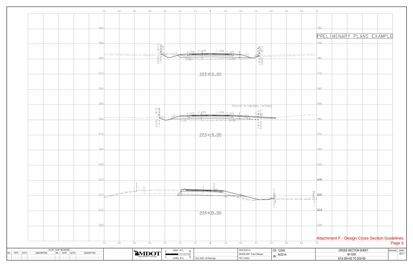
Cross Section Sheets The full set of design cross sections shall be provided with plan set submittals (Base, Preliminary, and OEC) for review, and at final Plan Turn In (see RID requirements). It is the intent that at plan submittal time, the project team or designer will cut cross sections at where the project stands at the time of submittal and submit with plan set(s). It is not intended that the design cross sections require additional detailing and clean up at any submittal prior to final Plan Turn In. At final Plan Turn In, provide final, detailed, design cross sections. Base Plans Submittal, Preliminary Plans & OEC:
• Cross Section Cell with station • Grid line elevations • Existing Ground/Surface • Proposed Top Surface • Proposed Agg Base • Proposed Subbase • Tie point where the PR surface meets EX ground • Slopes of pavement and shoulders • Ditch slopes • Subbase Slopes • EX and PR ROW lines • Excavation Limits
Final Plan Turn In are 100% complete.
• Offset distance of the pavement edges from the center line • Elevation at the pavement edges • Ditch bottom elevation • Dependent or Independent Ditch label • Driveway and Side Road ties • Guardrail
Attachment F - Design Cross Section Guidelines Page 1

RdBedPrEmbank_Pt11
CnGPr_Pt2
TrvlPrLn3Bot
TrvlPrHMA_Pt
TrvlPrConc_Pt_Edge
RdBedPrBaseAgg_Pt31
TrvlPrConc_Pt_Edge1
TrvlPrHMA_Pt5
RdBedPrBaseAgg_Pt21
CnGPr_Pt11
CnGPr_Pt_All_GutLn1
RdBedPrBaseAgg_Pt32
TrvlPrPrkLnLv1
RdBedPrEmbank_Pt211 TrvlPrPrkLn
TrvlPrConc_Pt1
TrvlPrHMA_Pt_Edge
TrvlPrConc_Pt2
TrvlPrHMA_Pt1
TrvlPrAll_Pt_CrnJt
TrvlPrPrkLnBot
RdBedPrEmbank_Pt21
CnGPr_Pt_C3_BkTrvlPrHMA_Pt3
TrvlPrConc_Pt
CnGPr_Pt_All_CurbFc1
TrvlPrHMA_Pt11
CnGPr_Pt_All_CurbFc2
TrvlPrConc_Pt11
CnGPr_Pt_C3_Bk1
TrvlPrHMA_Pt_Edge1
TrvlPrLn3
RdBedPrBaseAgg_Pt1
RdBedPrBaseAgg_Pt2
SlopePr_Pt_SSL_1:6Fill1
RdBedPrBaseAgg_Pt231
RdBedPrBaseAgg_Pt3
SlopePr_Pt_SSL_1:6Fill
CnGPr_Pt
RdBedPrBaseAgg_Pt11
CnGPr_Pt_All_GutLn
CnGPr_Pt12
RdBedPrBaseAgg_Pt22
RdBedPrBaseAgg_Pt12
TrvlPrLn3Lv1
TrvlPrHMA_Pt51
CS:
JN:
TSC:
DATE:
FILE:
DESIGN UNIT:DESCRIPTIONAUTH
DRAWING SHEETAS-LET PLAN REVISIONS
54321 XS-Sheet.dgn
M-2000
XSHEET
12345
54321A
05/01/12AS-BUILT PLAN REVISIONSADDENDUM PLAN REVISIONS FINAL ROW PLAN REVISIONS ( SUBMITTAL DATE: )
0
0 5
5
VERT. (FT)
HORZ. (FT)
Project Manager
Location
DESCRIPTIONAUTH
M-2000
STA 25+00.00 TO 28+00.00
CROSS SECTION SHEET
SECT 1NO. DATE
Michigan Department of Transportation
NO. DATE
990
980
970
960
0 1010 2020 3030 4040 5050 6060 707080 8080
0 1010 2020 3030 4040 5050 6060 707080 8080
990
980
970
960
BASE PLANS EXAMPLE
Attachment F - Design Cross Section Guidelines Page 2
E
DG
E
OF
GR
AV
EL
E
DG
E
OF
GR
AV
EL
4.00%
1:3
EX
CA
V.
LI
MI
TS
981.53
1:2
2.0%
-2.00% -2.00% 4.00%1:3
EX
CA
V.
LI
MI
TS
2.0%
-5.61%
PRIVATE BITUMINOUS ENTRANCE
E
DG
E
OF
GR
AV
EL
E
DG
E
OF
GR
AV
EL
EX
R/
W
EX
R/
W
4.00%
1:3
EX
CA
V.
LI
MI
TS
98
3.4
1
1:2
2.0%
-2.00% -2.00% 4.00%1:3
EX
CA
V.
LI
MI
TS
98
2.3
1
1:2
2.0%
00 1010 2020 3030 4040 5050 6060 7070
970 970
980 980
990 990
960 960
970 970
980 980
990 990
960 960
960 960
203+19.00
203+50.00
00 1010 2020 3030 4040 5050 6060 7070
CS:
JN:TSC:
DATE:
FILE:
DESIGN UNIT:
54321_XS-Sheet.dgn Location
12345
54321A
CROSS SECTION SHEET
Project Manager
0
0 10
10Michigan Department of Transportation
VERT. (FT)
HORZ. (FT)
DRAWING SHEET
M-1000
STA 203+00 TO 203+50
05/01/12AS-LET PLAN REVISIONS
NO.
NO.
DATE DESCRIPTION
AUTH
DATE
AUTH DESCRIPTION
SECT 1
610 610
620 620
630 630
640 640
600 600
610
620
630
610
620
630
E
X
EO
P
E
X
EO
P
E
X
PA
VE
D
SH
LD
R
E
X
PA
VE
D
SH
LD
R
EX
R/
W
LA
EX
R/
W
LA
7771 2900901
100
101
101102103104105
102
102103104105
103
103104105
104
104105
105107
106
105
ep1979998 400
981 - xy PGL
982 - Ditch Depth
987
3.13%
500
12 900901100980101101102103104105
102102103104105
103103104105
104104105
105
12 195196 ep99 98
200ps
4.00%201203
202204
203
204
210as
211 212
213 213
214
400
981 - xy PGL
982 - Ditch Depth
400
401
1:4
402
403
EX
CA
V.
LI
MI
TS
61
8.
31
1:4
215 216
116
2.0%dl
tie
dfl
dhp
4
1
4 515
1
4
1
4 515
1
203+00.00
PRELIMINARY PLANS EXAMPLE
Attachment F - Design Cross Section Guidelines Page 3

00 1010 2020 3030 4040 5050 6060 7070
00 1010 2020 3030 4040 5050 6060 7070
CS:
JN:TSC:
DATE:
FILE:
DESIGN UNIT:
54321_XS-Sheet.dgn Location
12345
54321A
CROSS SECTION SHEET
Project Manager
0
0 10
10Michigan Department of Transportation
VERT. (FT)
HORZ. (FT)
DRAWING SHEET
M-1000
STA 203+00 TO 203+50
10/07/12AS-LET PLAN REVISIONS
NO.
NO.
DATE DESCRIPTION
AUTH
DATE
AUTH DESCRIPTION
SECT 1
E
DG
E
OF
GR
AV
EL
E
DG
E
OF
GR
AV
EL
OF
F -12.00’
EL 982.93
4.00%
1:3
IN.DT.
979.83
EX
CA
V.
LI
MI
TS
981.53
1:2
2.0%
OF
F 12.00’
EL 982.93
-2.00% -2.00% 4.00%1:3
IN.DT.
EX
CA
V.
LI
MI
TS
980.28
2.0%
-5.61%
PRIVATE BITUMINOUS ENTRANCE
E
DG
E
OF
GR
AV
EL
E
DG
E
OF
GR
AV
EL
EX
R/
W
EX
R/
WOF
F -1
2.0
0’
EL 9
83.4
0
4.00%
1:3
IN.DT.
98
1.1
0
EX
CA
V.
LI
MI
TS
98
3.4
1
1:2
2.0%
OF
F 1
2.0
0’
EL 9
83.4
0
-2.00% -2.00% 4.00%1:3
IN.DT.
98
0.7
5
EX
CA
V.
LI
MI
TS
98
2.3
1
1:2
2.0%
970 970
980 980
990 990
960 960
970 970
980 980
990 990
960 960
960 960
203+19.00
203+50.00
610 610
620 620
630 630
640 640
600 600
E
X
EO
P
E
X
EO
P
E
X
PA
VE
D
SH
LD
R
E
X
PA
VE
D
SH
LD
R
EX
R/
W
LA
EX
R/
W
LA
777
PG
L
EL
62
3.
61
1 2900901
100
101
101102103104105
OF
F -
16.
00’
EL
62
3.
93
102
102103104105
103
103104105
104
104105
105107
106
105
ep1979998 400
981 - xy PGL
982 - Ditch Depth
987
3.13%
SIDE ROAD FOUND
500
12 900901100980101101102103104105
102102103104105
103103104105
104104105
105
12 195196 ep99 98
200ps
4.00%201203
202204
203
204
210as
211 212
213 213
214
400
981 - xy PGL
982 - Ditch Depth
400
401
1:4
IN.DT.
402
61
7.
32
403
EX
CA
V.
LI
MI
TS
61
8.
31
1:4
215 216
116
2.0%dl
tie
dfl
dhp
4
1
4 515
1
4
1
4 515
1
203+00.00
FINAL PLANS EXAMPLE
Attachment F - Design Cross Section Guidelines Page 4

Adaptation of Proposed Alignment/ROW Concepts Page 1
Adaptation of Proposed Alignment/ROW Concepts
The following guidance is for the proposed conceptual changes to MDOT standards for alignment definitions and annotation within plan sets and in practice.
Proposed Design Process & Plan Changes: Right of Way (ROW) acquisitions are to be based on previously established legal alignments, as retraced for the project, whenever possible. The appropriate project personnel (designer, surveyor and/or real estate technician) should determine when it may be necessary to depart from the previously established legal alignment for acquisition. (In circumstances where the route is entirely new or significantly departs from existing alignment it may be necessary to create new legal alignments.) Alignment/ROW Sheets It is intended that combined Alignment/ROW Sheets will be included in all plan sets. Alignment/ROW Sheets shall include the following components:
• All pertinent alignments to the project, relative to the public land survey system (PLSS), as provided by the surveyor, plus any alignments for the project as proposed by the engineer.
• All pertinent PLSS corners and government lines. • ROW limits dimensioned from the legal alignments from which the limits were
established. • All applicable project ties for alignments, ROW, and government lines. • Curve data for all project alignments shall be shown on the Alignment/ROW Sheets only.
Curve data shall be placed once on the Alignment/ROW Sheet of which the curves point of intersection (PI) station is located.
• Plat/subdivision information shall be shown on the Alignment/ROW sheets, as well as on the Removal and Construction sheets.
• MDOT parcel numbers and property boundary information shall be shown on the Alignment/ROW sheets only.
Please note that:
• These sheets may be best represented at the same scale as the project Removal and Construction Sheets.
• The detailed alignment, ROW, and government line ties should only be shown on the Alignment/ROW Sheets, and should not be repeated on the Removal and Construction Sheets.
Removal & Construction Sheets
• The Removal and Construction Sheets shall only include the alignment required to construct the project.
• In instances where a proposed construction alignment is required on a project, and intended to be used for ROW acquisition, it shall be designated/annotated as legal on the plans.
• PC, PI, and PT station labels shall be shown for the alignment shown (the alignment required to construct the project).

Adaptation of Proposed Alignment/ROW Concepts Page 2
Typical Sheets Typicals shall only include the alignment required to construct the project (the same alignment shown/called out on the Removal and Construction Sheets). An overall right of way dimension shall be included. Alignment Definitions & Key Alignment types (As-Constructed, Construction, or Survey) of existing alignments are determined by their historic origin and shall be provided by the surveyor. Plan users will refer to the Alignment Key (as described in this document) for alignment clarification and historical origin. For alignment definitions, please reference the MDOT 2012 Design Surveys Standards of Practice – Alignment Section (Pages 16-20). An Alignment Key shall be included on the first Alignment/ROW Sheet included in the project plan set. The key shall provide descriptions of each alignment included in the project. The key shall include descriptions/definitions of existing/retraced project alignments as provided by the surveyor as a survey deliverable. A description of any proposed alignments shall be provided by the designer. Annotation of Alignments: Annotation along the alignments shall be as follows: ROADWAY + LEGAL or NON-LEGAL + ALI In instances where there are recurring alignments, a sequential letter designation shall be used, with the letter coinciding with information found in the alignment key. Example Alignment Annotations: M-3 LEGAL ALI M-3 NON-LEGAL ALI US-2 NON-LEGAL (A) ALI US-2 NON-LEGAL (B) ALI US-2 LEGAL (A) ALI US-2 LEGAL (B) ALI Alignment Key: Alignment definitions/descriptions provided in the Alignment Key shall include the following: Retraced Alignments (provided with survey deliverables):
• Route Name • Origin Name, Origin Year and Origin Job Number • “as retraced for” Job Number • Year of Retracement
Proposed Construction Alignments (provided by the engineer):
• “Construction” • “Alignment for” + Job Number • Description of what the alignment is for and/or how it was produced
Example Alignment Key:

Adaptation of Proposed Alignment/ROW Concepts Page 3
M-43 LEGAL (A) ALI = M-43 1954 Construction Alignment from Project 82-24 as retraced for Job Number 111659 in 2011. M-43 LEGAL (B) ALI = Construction Alignment for Job Number 111659 for the relocated curve from station 119+00 to 321+96. Intended for acquisition on this project. WB I-96 NON-LEGAL ALI = Construction Alignment for WB I-96 lanes as proposed by engineer for Job Number 123658.
Questions or comments regarding this document please contact [email protected]

FINAL ROW PLAN REVISIONS (SUBMITTAL DATE )
NO SCALE DATE: CS: PLAN GUIDELINES DRAWING SHEET
NO. DATE AUTH DESCRIPTION NO. DATE AUTH DESCRIPTION DESIGN UNIT: JN: ALIGNMENT/ROW SHEETS SECT 1
FILE: TSC:
ALIGNMENT/ROW SHEETS: 1. Label all roadway names and county drains at the outside of the sheet using MDOT Pr x 1.5 text size. 2. Label all alignments using current naming convention. 3. Place north arrow (upper right corner when possible). 4. Show section, township and range information, and city, village, township or county. 5. ROW is dimensioned only to the legal alignments. If a legal alignment is not available then the ROW
is dimensioned from ROW line to ROW line. Label ROW within the sheet every time it changes. Label and dimension proposed ROW.
6. An alignment key is required and should be located in the upper left corner of the first alignment sheet. 7. Show section corners, quarter corners, section lines, bearings of the section lines and distances as
shown. The section corner information will only be shown on the alignment sheets. 8. All crossroad alignment ties will only be shown on the alignment sheets. Only tie the section lines and
crossroads to the legal alignment. 9. Show tangent bearings on all alignments. 10. Existing and proposed alignment curve data is only shown on the alignment sheets. Show the curve
data on the sheet where the PI appears. Show existing and proposed superelevation 11. Dimension the distances between alignments. 12. Show all parcel and plat lines on the alignment sheets. Parcel lines are not shown on the removal and
construction sheets. 13. Label all subdivisions and plats. Label with proposed text size and on the appropriate level. 14. If a POT is shown at the end/beginning of an alignment, northing and eastings shall be included to
establish the location. 15. The POB/POE, job number, control section and mile points, and physical reference and mile points
need to be shown at the beginning and end of the construction limits. 16. If the existing ROW has been established from survey and it is not dependent on the legal alignment,
label the bearing and distance of the existing ROW and the station of the location that the ROW is no longer dependent on the legal alignment.
17. Label and dimension any existing or proposed easements. 18. Use the standard Geopak orientation for labeling PC, PI & PT locations whenever possible. These can
be modified if readability becomes an issue. 19. Parcel numbers and property boundary information shall be shown on the Alignment/ROW sheets only. 20. Use separate sheets for ramp and/or crossroad alignments as needed, only show the information once. 21. The scale of the Alignment/ROW sheets is at the discretion of the designer. Due to the amount of
information shown on these sheets it may be beneficial to use the same scale as the removal and construction sheets.
22. Show all station equations.
Attachment H - Alignment/ROW Sheet Examples Page 1

POT=253+16.71
PC
=258+
00.0
0P
C=
258+
00.0
0
NO
N-
LE
GA
L
ALI
NB
US-31
LEGAL ALI
NB US-31
POT=253+16.71
PI 254+57.72 NB US-31 LEGAL ALI =
N = 480202.82, E = 12662266.88
POT 100+00.00 LAKEWOOD BLVD LEGAL ALI
PI 254+57.72 NB US-31 NON-LEGAL ALI =
E = 12662261.01
N = 480053.32
E = 12662308.76
N = 480068.17
PI 254+57.72 SB US-31 NON-LEGAL (B) ALI =
N = 480187.97, E = 12662219.14
PI 254+57.72 SB US-31 NON-LEGAL (A) ALI
NON-LEGAL (B) ALI
SB US-31
NO
N-
LE
GA
L (A)
ALI
SB
US-31
PI
= 260
+06.1
7PI
= 260
+06.1
7
10 11
12 13
14
15
16
TS=
12+
15.4
7
SC=14+15.4
7
PI=13+49.35
254 255 256 257 258 259 260
254 255 256 257 258 259 260
255 256 257 258 259 260
255 256 257 258 259 260
97
98
99
100
101
102
L = 200.00’
X = 198.45’
Y = 18.51’
K = 99.74’
P = 4.64’
LT = 133.88’
ST = 67.17’
TS N = 480,297.14 E = 12,662,271.70= 12+15.47
PI N = 480,426.47 E = 12,662,237.08= 13+49.35
SC N = 480,493.62 E = 12,662,238.27= 14+15.47
LAKEWOOD BLVD RAMP E NON-LEGAL ALI
T = 133,156.67’
L = 1,123.08’
R = 358.10’
E = 132,799.05’
SC N = 480,493.62 E = 12,662,238.27= 14+15.47
PI N = 613,629.43 E = 12,664,595.44= 1345+72.14
PT N = 480,482.87 E = 12,662,954.38= 25+38.55
¸% = 0.62%
LAKEWOOD BLVD RAMP E NON-LEGAL ALI
EX & PROP SUPER =7.0%
LAKEWOOD BLVD
LAKEWOOD BLVD RAMP E
� CORNER SECTION 21 & 22
N = 480179.22, E = 12664181.59
CENTER CORNER SECTION 21
N = 480211.82, E = 12661536.58
E-
W � SE
CTIO
N LIN
E
22
21
21
22
S 89° 17’
38"
E
21
2121
21
PR BMP 2.613 NB US-31
PR 742605
CS BMP 0.618 NB US-31
PR BMP 2.605 SB US-31
PR 740406
CS BMP 0.614 SB US-31
2645.2
1’
1884.6
9’
52.5
7’
677.7
8’
LEGAL ALI
NB US-31
NON-LEGAL ALI
NB US-31
EX
LA
RO
W
VA
RIE
SE
X
LA
RO
W
VA
RIE
S
50’
LEGAL ALI
LAKEWOOD BLVD
ALIGNMENT KEY
N
30.1
7’
RAMP E NON-LEGAL ALI
LAKEWOOD BLVD
NON-LEGAL (A) ALI
SB US-31
NON-LEGAL (B) ALI
SB US-31
61
2
2
2
3
4
5
8
9
7
7
15
15
11
14
14
LAKEWOOD BLVD RAMP E NON-LEGAL ALI: LAKEWOOD BLVD RAMP E CONSTRUCTION ALIGNMENT AS PROPOSED FOR JN 88876A
LAKEWOOD BLVD RAMP D NON-LEGAL (A) ALI: LAKEWOOD BLVD RAMP D CONSTRUCTION ALIGNMENT AS PROPOSED FOR JN 88876A
LAKEWOOD BLVD RAMP A NON-LEGAL (A) ALI: LAKEWOOD BLVD RAMP A CONSTRUCTION ALIGNMENT AS PROPOSED FOR JN 88876A
SB US-31 NON-LEGAL (A) ALI: SB US-31 CONSTRUCTION ALIGNMENT AS PROPOSED FOR JN 88876A
NB US-31 NON-LEGAL ALI: NB US-31 CONSTRUCTION ALIGNMENT AS PROPOSED FOR JN 88876A
LAKEWOOD BLVD RAMP D NON-LEGAL (B) ALI: EX LAKEWOOD BLVD RAMP D 1955 CONSTRUCTION ALIGNMENT FROM PROJECT 82-27 AS RETRACED FOR JN 88876A IN 2011
LAKEWOOD BLVD RAMP A NON-LEGAL (B) ALI: EX LAKEWOOD BLVD RAMP A 1955 CONSTRUCTION ALIGNMENT FROM PROJECT 82-27 AS RETRACED FOR JN 88876A IN 2011
SB US-31 NON-LEGAL (B) ALI: EX SB US-31 1955 CONSTRUCTION ALIGNMENT FROM PROJECT 82-27 AS RETRACED FOR JN 88876A IN 2011
NB US-31 LEGAL ALI: NB US-31 1955 CONSTRUCTION ALIGNMENT FROM PROJECT 82-27 AS RETRACED FOR JN 88876A IN 2011
N=480088.99 E=12662327.41
STA 253+31.05 NB US-31 LEGAL ALI, 24’ RT
RAMP E NON-LEGAL ALI =
POT 10+00.00 LAKEWOOD BLVD10
HOLLAND TWP
T5N, R15W
SECTION 21
HOLLAND TWP
T5N, R15W
SECTION 21
18
P.O.B. STA 255+16.38 NB US-31
JOB NUMBER 88876A
CONTROL SECTION 70013
POB STA 255+32.58 SB US-31
JOB NUMBER 88876A
CONTROL SECTION 70013
21 CS:
JN:
TSC:
DATE:
FILE:
DESIGN UNIT:DESCRIPTIONAUTH
DRAWING SHEET
FINAL ROW PLAN REVISIONS ( SUBMITTAL DATE: )
0 80
HORZ. (FT)
DESCRIPTIONAUTH
SECT 1
Michigan Department of Transportation
DATE NO. DATENO.
ALIGNMENT/ROW SHEET
US-31 STA 253+16.71 TO STA 260+00 US31
ALI
001
Attachment H - Alignment/ROW Sheet Examples Page 2

PT
=266+
24.6
4P
T=
266+
24.6
4
PI
= 264+
18.4
9PI
= 264+
18.4
9
PR
C=
262+
12.3
2P
RC
=262+
12.3
2
PI
= 260
+06.1
7PI
= 260
+06.1
7
27
28
29 30 31
22
23
24
260 261 262 263 264 265 266 267 268 269 270
260 261 262 263 264 265 266 267 268 269 270
27
28
29 30 31
22
23
24
261
260 261 262 263 264 265 266 267 268 269 270
260 262 263 264 265 266 267 268 269 270
T = 206.17’
L = 412.32’
R = 17,000.00’
E = 1.25’
PC N = 480,529.65 E = 12,662,165.20= 258+00.00
PI N = 480,726.51 E = 12,662,103.95= 260+06.17
PRC N = 480,924.80 E = 12,662,047.49= 262+12.32
T = 206.17’
L = 412.32’
R = 17,000.00’
E = 1.25’
PRC N = 480,924.80 E = 12,662,047.49= 262+12.32
PI N = 481,123.09 E = 12,661,991.03= 264+18.49
PT N = 481,319.95 E = 12,661,929.79= 266+24.64
NB US-31 NON-LEGAL ALI NB US-31 NON-LEGAL ALI
PR SUPER =N.C. PR SUPER =N.C.
T = 206.17’
L = 412.32’
R = 17,000.00’
E = 1.25’
PC N = 480,514.79 E = 12,662,117.45= 258+00.00
PI N = 480,711.66 E = 12,662,056.20= 260+06.17
PRC N = 480,906.98 E = 12,661,990.20= 262+12.32
T = 206.17’
L = 412.32’
R = 17,000.00’
E = 1.25’
PRC N = 480,906.98 E = 12,661,990.20= 262+12.32
PI N = 481,102.29 E = 12,661,924.19= 264+18.49
PT N = 481,299.16 E = 12,661,862.95= 266+24.64
SB US-31 NON-LEGAL ALI SB US-31 NON-LEGAL ALI
PR SUPER =N.C. PR SUPER =N.C.
RAMP D
RAMP A
EX 75’
LA
RO
WE
X
LA
RO
W
VA
RIE
S
70’
LEGAL ALI
NB US-31
NON-LEGAL ALI
NB US-31
EX
LA
RO
W
VA
RIE
SE
X
LA
RO
W
VA
RIE
SN
RAMP D NON-LEGAL (A) ALI
LAKEWOOD BLVD
60’
10’
RAMP D NON-LEGAL (B) ALI
LAKEWOOD BLVD
RAMP A NON-LEGAL (A) ALI
LAKEWOOD BLVD
RAMP A NON-LEGAL (B) ALI
LAKEWOOD BLVD
NON-LEGAL (A) ALI
SB US-31
NON-LEGAL (B) ALI
SB US-31
EX 158’
LA
RO
W267+
91.0
2
3
5
4
10
16
16
1111
5
2
2
9
268+
68.8
4E
X 75’
LA
RO
W
324.9’
90.78’
208.97’
N 1°51’32" W
N 10°50’24" W
20 SEE RAMP ALIGNMENT SHEETS FOR LAKEWOOD BLVD RAMP ALIGNMENT INFORMATION
HOLLAND TWP
T5N, R15W
SECTION 21
HOLLAND TWP
T5N, R15W
SECTION 21
16
16
50’
10’
18
21 CS:
JN:
TSC:
DATE:
FILE:
DESIGN UNIT:DESCRIPTIONAUTH
DRAWING SHEET
FINAL ROW PLAN REVISIONS ( SUBMITTAL DATE: )
0 80
HORZ. (FT)
DESCRIPTIONAUTH
SECT 1
Michigan Department of Transportation
DATE NO. DATENO.
ALIGNMENT/ROW SHEET
US-31 STA 260+00 TO STA 270+00 US31
ALI
002
Attachment H - Alignment/ROW Sheet Examples Page 3

1
NORTH PARK OUTLOT SUB
31 32 33 34
25 26
27
270 271 272 273 274 275 276 277 278 279 280
270 271 272 273 274 275 276 277 278 279 280
31 32 33 34 35 36 37
25 26
27
270 271 272 273 274 275 276 277 278 279 280
270 271 272 273 274 275 276 277 278 279 280
RA
MP
A
CENTER CORNER SECTION 21
N = 480211.82, E = 12661536.58
N = 482869.77, E = 12661564.55
1/4 CORNER SECTION 21 & 16
N-S � SECTION LINE
21
21
21
21
S 0° 36’ 10" W
21
21
16
16
EX 90’
LA
RO
WE
X 125’
LA
RO
W
2066.55’
195.37’
363.62’
32.56’
2658.10’
70’
LEGAL ALI
NB US-31
TO GRADE
CONSENT
TO PARCEL LINE
NON-LEGAL ALI
NB US-31
EX 75’
LA
RO
WE
X
LA
RO
W
VA
RIE
S
EX 125’
LA
RO
W
EX 75’
LA
RO
W
DR
AIN
AG
E
EX 40’
EA
SE
ME
NT
N
+00.0
0
CONSTRUCT SIDEWALK
CONSENT TO
5’ 1
0’
60’
10’
RAMP D NON-LEGAL (A) ALI
LAKEWOOD BLVD
RAMP D NON-LEGAL (B) ALI
LAKEWOOD BLVD
RAMP A NON-LEGAL (A) ALI
LAKEWOOD BLVDRAMP A NON-LEGAL (B) ALI
LAKEWOOD BLVD
NON-LEGAL (B) ALI
SB US-31
NON-LEGAL (A) ALI
SB US-31
EX 90’
LA
RO
W
7
7
2
2
3
4
55
9
11 11
16
16
17
13
1212
305.68’
N 15°29’50" W
100 101
19
1919
19
20 SEE RAMP ALIGNMENT SHEETS FOR LAKEWOOD BLVD RAMP ALIGNMENT INFORMATION
HOLLAND TWP
T5N, R15W
SECTION 21
HOLLAND TWP
T5N, R15W
SECTION 21
SEE DETAIL A
DETAIL A
273+
04.2
0
15.8’
276+70.92, 75’ RT
276+66.06, 90’ RT
21 CS:
JN:
TSC:
DATE:
FILE:
DESIGN UNIT:DESCRIPTIONAUTH
DRAWING SHEET
FINAL ROW PLAN REVISIONS ( SUBMITTAL DATE: )
0 80
HORZ. (FT)
DESCRIPTIONAUTH
SECT 1
Michigan Department of Transportation
DATE NO. DATENO.
ALIGNMENT/ROW SHEET
US-31 STA 270+00 TO STA 280+00 US31
ALI
003
Attachment H - Alignment/ROW Sheet Examples Page 4

1
VAN OMMEN PLAT
34
POT 282+52.51 NB US-31 LEGAL ALI =
POT 100+00.00 JAMES ST LEGAL ALI
280 281 282 283 284 285 286 287 288 289 290
280 281 282 283 284 285 286 287 288 289 290
280 281 282 283 284 285 286 287 288 289 290
280 281 282 283 284 285 286 287 288 289 290
97
98
99
100
101
JAMES ST
JAMES ST
21
16
21
16
N = 482869.77, E = 12661564.55
1/4 CORNER SECTION 21 & 16
CENTER CORNER SECTION 21
21 21
2121
N = 480211.82, E = 12661536.58
N = 482837.64, E = 12664224.78
SECTION CORNER - SECTION 21, 16, 15, 22
21
2215
16CENTER CORNER SECTION 16
1616
16
16
N = 485509.54, E = 12661596.98
N = 482904.54, E = 12658886.86
SECTION CORNER - SECTION 20, 17, 16, 21
20
21 16
17
N-S 1/4 SECTION LINE
N-S 1/4 SECTION LINE
E-
W SE
CTIO
N LIN
E
E-
W SE
CTIO
N LIN
E
S 89° 18’
29"
E
S 0° 36’ 10" W
S 0° 42’ 14" W
N 89° 15’
22"
W
EX 90’
LA
RO
WE
X 125’
LA
RO
W
EX 75’
LA
RO
WE
X 125’
LA
RO
W
2658.10’
2660.4
2’
2639.97’
117.4
3’
63.1
0’
10.52’
2486.8
7’
2677.9
2’
TO GRADE
CONSENT
TO EX ROW
70’
LEGAL ALI
NB US-31
EX 86’ ROW
NON-LEGAL ALI
NB US-31
EX 75’
LA
RO
W
EX 125’
LA
RO
W
EX 66’ ROW
N
LEGAL ALI
JAMES ST
ROW
PROP
10’
50’
10’
145’
TO LOT LINE
ALONG LOT LINE
TO EX LA ROW
TO EX LA ROW
EX 90’
LA
RO
W
EX 125’
LA
RO
W
284+
09.7
9
280
+65.2
4
282+47.96
284+74.84
NON-LEGAL (A) ALI
SB US-31
34
1
5
5
5
7
7
52
2
5
8
9
9
12 12
13
16
16
11
101 102 103
125.28’
200.28’
138.59’
N 21°1
9’47" E
N 45
°0’43" W
N 21°2
0’3" E
19
19
19
19
HOLLAND TWP
T5N, R15W
SECTION 21
HOLLAND TWP
T5N, R15W
SECTION 16
HOLLAND TWP
T5N, R15W
SECTION 21
HOLLAND TWP
T5N, R15W
SECTION 16
10’
NON-LEGAL (B) ALI
SB US-31
21 CS:
JN:
TSC:
DATE:
FILE:
DESIGN UNIT:DESCRIPTIONAUTH
DRAWING SHEET
FINAL ROW PLAN REVISIONS ( SUBMITTAL DATE: )
0 80
HORZ. (FT)
DESCRIPTIONAUTH
SECT 1
Michigan Department of Transportation
DATE NO. DATENO.
ALIGNMENT/ROW SHEET
US-31 STA 280+00 TO STA 290+00 US31
ALI
004
Attachment H - Alignment/ROW Sheet Examples Page 5


