
David Luebke 04/20/23
CS 551 / 645: Introductory Computer Graphics
David Luebke
http://www.cs.virginia.edu/~cs551

David Luebke 04/20/23
Administrivia
Course evaluations on the web– Help make this class better next semester
Looking into alternative location for final– Who wants to move?
David Luebke 04/20/23
The Plan
Today– Finish up radiosity– Recap up till midterm
Tomorrow– Recap since midterm

David Luebke 04/20/23
Recap: Radiosity Fundamentals
Model light transfer between patches as a system of linear equations
Solving this system gives the intensity at each patch– Simplifying assumptions:
Environment is closed All surfaces are Lambertian (perfectly diffuse) reflectors
– Solving for R, G, B intensities produces color at each patch
Render patches as colored polygons

David Luebke 04/20/23
Recap: Radiosity Fundamentals
Radiosity is the rate at which energy leaves a surface
Radiosity = rate at which the surface emits energy + rate at which the surface reflects energy– Notice: previous methods distinguish light sources
from surfaces– In radiosity all surfaces can emit light– Thus: all emitters inherently have area

David Luebke 04/20/23
Recap: The Radiosity Equation
For each patch i:
Bi = Ei + i Bj Fji (Aj / Ai)where
Bi, Bj= radiosity of patch i, j
Ai, Aj= area of patch i, j
Ei = energy/area/time emitted by i
i = reflectivity of patch i
Fji = Form factor from j to i
David Luebke 04/20/23
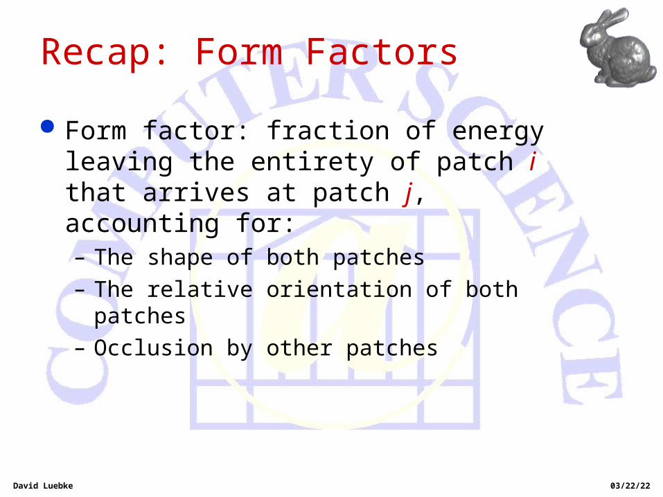
Recap: Form Factors
Form factor: fraction of energy leaving the entirety of patch i that arrives at patch j, accounting for:– The shape of both patches– The relative orientation of both patches– Occlusion by other patches
David Luebke 04/20/23
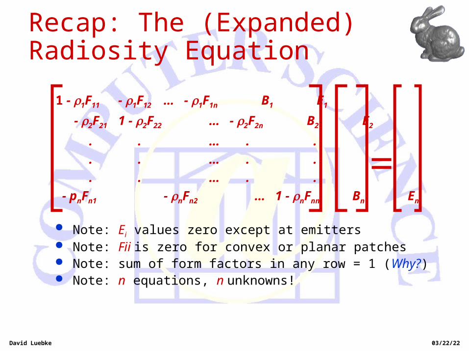
Recap: The (Expanded) Radiosity Equation
1 - 1F11 - 1F12 … - 1F1n B1 E1
- 2F21 1 - 2F22 … - 2F2n B2 E2
. . … . . .
. . … . . .
. . … . . .
- pnFn1 - nFn2 … 1 - nFnn Bn En
Note: Ei values zero except at emitters Note: Fii is zero for convex or planar patches Note: sum of form factors in any row = 1 (Why?) Note: n equations, n unknowns!

David Luebke 04/20/23
Recap: Evaluating Form Factors (Hemicubes) Hemicube algorithm: Think Z-buffer
– Render the model onto a hemicube as seen from the center of patch i
– Store item IDs instead of color
– Use Z-buffer to resolve visibility Advantages of hemicubes
– Solves shape, size, orientation, and occlusion problems in one framework
– Can use hardware Z-buffers to speed up form factor determination (How?)

David Luebke 04/20/23
Recap: Hemicubes
Disadvantages of hemicubes? – Aliasing! Low resolution buffer can’t capture
actual polygon contributions very exactly Causes “banding” near lights (plate 41)
– Actual form factor is over area of patch; hemicube samples visibility at only center point on patch

David Luebke 04/20/23
Form Factors: Ray Casting
Idea: shoot rays from center of patch in hemispherical pattern

David Luebke 04/20/23
Form Factors: Ray Casting
Advantages:– Hemisphere better approximation than hemicube
More even sampling reduces aliasing
– Don’t need to keep item buffer– Slightly simpler to calculate coverage
David Luebke 04/20/23
Form Factors: Ray Casting
Disadvantages:– Regular sampling still invites aliasing – Visibility at patch center still isn’t quite the same
as form factor– Ray tracing is generally slower than
Z-buffer-like hemicube algorithms Depends on scene, though What kind of scene might ray tracing actually be faster
on?

David Luebke 04/20/23
Form Factors
Source-to-vertex form factors– Calculating form factors at the patch vertices
helps address some problems:for every patch vertex
for every source patch
sample source evenly with rays
visibility = % rays that hit
– What are the problems with this approach?

David Luebke 04/20/23
Form Factors
Summary of form factor computation– Analytical:
Expensive or impossible (in general case)
– Hemicube Fast, especially using graphics hardware Not very accurate; aliasing problems
– Ray casting Conceptually cleaner than hemicube Usually slower; aliasing still possible

David Luebke 04/20/23
Radiosity Continued
Lots more to know about radiosity:– Progressive radiosity: viewing an approximate
solution early– Hierarchical radiosity: increasing patch resolution
on an as-needed basis

David Luebke 04/20/23
Review for Exam
Quick recap of lecture topics for exam… – Display technologies
Vector versus raster: what’s a pixel? CRT (black & white, color): shadow mask, phosphors,
electron guns LCD: polarizing crystals that line up under an E-field,
losing their polarization and acting as light valves Pros and cons of different technologies
– Framebuffers Fast, dual-ported memory bank for holding pixels True-color (24-bit) vs Pseudocolor (8-bit indexed) vs hi-
color (16-bit, 6-6-4 ?)

David Luebke 04/20/23
Review For Exam
Color– Basic physiology: retina, rods, cones
– Different types of cones: L, M, S
– Metamers: perceptually identical color senstions caused by different spectra
– CIE Color Space (X, Y, Z) Color mix-and-match experiment Hypothetical light sources X, Y, Z (why?) Three dimensional shape, often simplified to 2-D gamut
– Other color spaces (RGB, HSV)
– Gamma correction: linearize non-linear response of display device
David Luebke 04/20/23
Review For Exam
Rasterizing lines– A methodology in optimizing code– Simplest way: solve slope-intercept equation
Check slope and step in X or Y
– DDA: find incremental change per inner loop– Bresenham: take advantage of rational slope,
endpoints to optimize with integer arithmetic

David Luebke 04/20/23
Review For Exam
Rasterizing polygons– Can break into triangles for convenience
Trivial for convex polys, difficult for complex polys
– Edge equations: Evaluate equation of edge (linear expression) per pixel If all three edges are positive, light pixel Can evaulate R,G,B, Z as linear expressions too Hardware: SIMD array Software: bounding box Issues: ensuring consistent edge equations, numerical
stability when evaluating edge equations

David Luebke 04/20/23
Review For exam
Rasterizing triangles: edge walking– Find edges (DDA)– Interpolate colors down edges– Interpolate colors across scanlines– Fast: touches only pixels necessary– Difficult: lots of special cases, fractional offsets,
precision worries
Rasterizing triangles: general issues– Need consistent rules about pixels right on edge

David Luebke 04/20/23
Review For Test
Can also rasterize general polygons– Active edge table: sort edges by ymin and ymax,
then by x intersection w/ scanline– March up scanline by scanline, filling pixels
according to parity rule– Hard to interpolate color, etc. correctly -- not
planar in color space, in general

David Luebke 04/20/23
Review For Test
Clipping– Want only portions of lines, polygons in viewport– Cohen-Sutherland line clipping: binary outcodes– Polygon clipping is harder
Triangle in, 7-gon out Concave polyon in, 2 polygons out
– Sutherland-Hodgman: clip against view planes in succession
In-out rules Line-plane intersection
David Luebke 04/20/23
Review For Test
Clipping in 3-D– Sutherland-Hodgman extends easily to clipping
against six view-frustum planes– Issue: when in the pipeline to clip?
World coordinates: arbitrary planes expensive Camera coordinates: two planes easy, four hard Canonical perspective coordinates: two easy, four okay Canonical orthographic coordinates/screen coordinates:
reduces matrix multiplies, requires clipping in homogeneous coordinates
Common shortcut: clip near-far in camera coordinates, multiply by perspective matrix, clip left-right-top-bottom

David Luebke 04/20/23
Review For Test
3-D graphics:
Transform
Illuminate
Transform
Clip
Project
Rasterize
Model & CameraModel & CameraParametersParameters Rendering PipelineRendering Pipeline FramebufferFramebuffer DisplayDisplay

David Luebke 04/20/23
Review For Test Rendering pipeline:
ModelingTransforms
Scene graphObject geometry
LightingCalculations
ViewingTransform
Clipping
ProjectionTransform
Result:Result:
• All vertices of scene in shared 3-D “world” coordinate All vertices of scene in shared 3-D “world” coordinate systemsystem
• Vertices shaded according to lighting modelVertices shaded according to lighting model
• Scene vertices in 3-D “view” or “camera” coordinate Scene vertices in 3-D “view” or “camera” coordinate systemsystem
• Exactly those vertices & portions of polygons in view Exactly those vertices & portions of polygons in view frustumfrustum
• 2-D screen coordinates of clipped vertices2-D screen coordinates of clipped vertices

David Luebke 04/20/23
Review For Test
Transformations– Shift in coordinate systems (basis sets)– Accomplished via matrix multiplication– Modeling transforms: object->world– Viewing transform: world->view– Projection transform: view->screen

David Luebke 04/20/23
Review For Test
Rigid-body transforms– Rotation: 2-D. 3-D (canonical & arbitrary axis)– Scaling– Translation: homogeneous coords, 4x4 matrices– Composiing transforms
Matrix multiplication Order from right to left
Projection transforms– Geometry of perspective projection– Derive perspective projection matrix


![CS551 Internet Architecture [Clark88a]merlot.usc.edu/cs551-m05/lectures/tentative/05_clark88.pdfa system of store-and-forward packet-switched gateways that provides unreliable packet](https://static.documents.pub/doc/80x56/609ff8e93097596c2242afdb/cs551-internet-architecture-clark88a-a-system-of-store-and-forward-packet-switched.jpg)


