

DDNC - DDICInstructions for applicationDIRECT DRIVE PACKAGE
B600 - MISTRAL - TYPHON II
INSTRUCTIONS 1401-R00 e
Section 1401
Effective October 2011
Replaces June 2011
This Instruction only contains direct drive package information. It is imperative to have in complement the
compressor one and also all the others relatives to the accessories, also the parts list before installing the
equipment.
INSTALLATIONOPERATION
MAINTENANCESAFETY
STORAGE
DDICDDNC
Original instructions
Your distributor :
Z.I. La Plaine des Isles - F 89000 AUXERRE - FRANCE
Tel. : +33 (0)3.86.49.86.30 - Fax : +33 (0)3.86.49.87.17
[email protected] - www.mouvex.com
2/24NT 1401-R00 10.11 Direct drive package DDNC DDIC e
MOUVEX TRUCK SCREW COMPRESSORSAFETY, STORAGE, INSTALLATION, OPERATION AND MAINTENANCE INSTRUCTIONS
MODELS : DDNC - DDIC DIRECT DRIVE PACKAGE
B600 - MISTRAL - TYPHON II
REMARKS :
MOUVEX truck screw-type compressors MUST be installed in sys-
tems designed by qualified personnel. The installation MUST be in
compliance with local standards, national regulations and rules of
safety.
This manual is designed to permit installation and commis-
sioning of MOUVEX truck screw-type compressors and MUST
accompany the compressor.
Maintenance of MOUVEX screw-type compressors must ONLY be
carried out by qualified technicians. This maintenance must meet
local and national standards as well as all safety regulations.
Read this manual, including all instructions and warnings, in
full BEFORE any use of MOUVEX compressors.
Do not remove the warning and use label stickers that are
found on the compressors.
ADDITIONAL DOCUMENTATION
The table below gives the list of instructions in addition
to this application instruction :
DDNC or DDIC
applicationInstructions Parts list
B600 20R/30R NT 1401-K00PL 1401-K01
PL 1401-R01
B600 13R/15L
B600 19R/22LNT 1401-K00
PL 1401-K01
PL 1401-Q01
PL 1401-R01
MISTRAL 20R/30R NT 1401-J00PL 1401-J01
PL 1401-R01
MISTRAL 13R/15L
MISTRAL 19R/22L NT 1401-J00
PL 1401-J01
PL 1401-Q01
PL 1401-R01
TYPHON II 20R/30R NT 1401-G00PL 1401-G01
PL 1401-R01
TYPHON II 13R/15L
TYPHON II 19R/22LNT 1401-G00
PL 1401-G01
PL 1401-Q01
PL 1401-R01
Torque limiter NT 1401-B00 -
Check and relief valve NT 1401-E00 -
1. OVERALL DIMENSIONS . . . . . . . . . . . . . . . . . . . . . . . . . .4
2. INSTALLATION . . . . . . . . . . . . . . . . . . . . . . . . . . . . . . . .162.1 Mounting location . . . . . . . . . . . . . . . . . . . . . . . . . . . .16
2.2 Mounting procedure . . . . . . . . . . . . . . . . . . . . . . . . . .16
2.3 At succion . . . . . . . . . . . . . . . . . . . . . . . . . . . . . . . . . .17
2.4 Check relief / Safety valve . . . . . . . . . . . . . . . . . . . . .18
2.5 Drive . . . . . . . . . . . . . . . . . . . . . . . . . . . . . . . . . . . . . .18
2.6 Electric circuit . . . . . . . . . . . . . . . . . . . . . . . . . . . . . . .19
2.7 Instrumentation . . . . . . . . . . . . . . . . . . . . . . . . . . . . . .21
2.8 Chair modification . . . . . . . . . . . . . . . . . . . . . . . . . . . .21
3. MAINTENANCE . . . . . . . . . . . . . . . . . . . . . . . . . . . . . . . .213.1 Maintenance schedules . . . . . . . . . . . . . . . . . . . . . . .21
3.2 Air filter replacement procedure . . . . . . . . . . . . . . . . .21
3.3 Cartridge replacement procedure . . . . . . . . . . . . . . . .21
3.4 Drive train inspection . . . . . . . . . . . . . . . . . . . . . . . . .21
3.5 Check valve and relief valve inspection . . . . . . . . . . .21
3.6 Warranty claims . . . . . . . . . . . . . . . . . . . . . . . . . . . . .21
4. TROUBLESHOOTING . . . . . . . . . . . . . . . . . . . . . . . . . . .22
5. STORAGE CONDITIONS . . . . . . . . . . . . . . . . . . . . . . . . .22
6. USE . . . . . . . . . . . . . . . . . . . . . . . . . . . . . . . . . . . . . . . . .22
7. SCRAPPING . . . . . . . . . . . . . . . . . . . . . . . . . . . . . . . . . .22
8. COMPRESSORS FORM INFORMATION . . . . . . . . . . . . .23
9. CERTIFICATE OF CONFORMITY . . . . . . . . . . . . . . . . . .24
TABLE OF CONTENTS Page
This is a SAFETY ALERT SYMBOL
When you see this symbol on the product, or in the manual, look
for one of the following signal words and be alert to the potential for
personal injury, death or major property damage.
Warns of hazards that WILL cause serious personal injury,
death or major property damage
Warns of hazards that CAN cause serious personal injury,
death or major property damage.
Warns of hazards that CAN cause personal injury or property
damage.
NOTICE
Indicates special instructions which are very important and
must be followed.
SAFETY INFORMATIONS
WARNING
CAUTION
DANGER

SAFETY CHECK LIST
1. Before operating the compressor, ensure the vessel to
which the compressor is connected is certified to withstand
the pressure and /or vacuum produced.
2. Verify adequately sized relief valves (if necessary, CE
approved) have been fitted to protect the vessel. Do not use
solvents or inflammable products for cleaning the pipelines and
the accessories.
3. Gas/air mixtures which are potentially volatile/explosive must
not be introduced or allowed to be introduced into the compres-
sor.
4. All pressure vessel and piping connected to the compres-
sor must be isolated and in a safe operating condition.
5. Operators should wear ear protection when operating truck
mounted compressors.
6. There are components within the compressor of sufficient
weight to cause injury if mishandled. Use proper lifting
devices as necessary.
7. Where necessary, this equipment should be grounded to
control static electricity.
8. The temperature of the air leaving the compressor is elevat-
ed above ambient due to air compression. Check that the
elevated temperatures do not adversely affect the product
and any material used in design of the system. Attach clear-
ly marked warning signs to warn of potentially hot surfaces
on the compressor, piping and accessories which will burn if
touched.
9. Mounting of the compressor must be correctly engineered
and the compressor must be properly secured. Refer to the
Compressor Mounting section of this manual.
NOTICE :MOUVEX COMPRESSORS ARE NOT DESIGNED FOR HANDLING
LIQUID, POWDER OR CONDENSATE. TO DO SO WILL VOID THE WAR-
RANTY.
LIFTING POINTS :
The compressor can be picked up from underneath to be trans-
ported.
THE NOISE EMITTED BY WORKING
MOUVEX SCREW COMPRESSOR CAN
BE HIGHER THAN 80 DBA.
THE END USERS MUST USE, WHEN
NECESSARY THE APPROPRIATE EAR
PROTECTIONS. FAILURE TO WEAR HEAR
PROTECTIONS IN AREAS WHERE THE
NOISE IS HIGHER THAN 80 DBA CAN
LEAD TO PERMANENT BODY DAMAGE.
WARNING
A loud noise can
cause permanent
body damage.
CONTENTS OF THE COMPRESSOR,
TANK, PIPING, AND FILTERS COULD BE
HAZARDOUS TO HEALTH. TAKE ALL
NECESSARY PRECAUTIONS WHEN PER-
FORMING COMPRESSOR SERVICE OR
MAINTENANCE.
WARNING
Hazardous or toxic
fluids can cause
serious injury.
COMPRESSOR, PIPING AND ACCESSO-
RIES WILL BECOME HOT DURING OPERA-
TION AND CAN CAUSE SERIOUS PERSO-
NAL INJURY.
CAUTION
Extreme heat can
cause injury or
property damage.
FAILURE TO INSTALL ADEQUATELY SIZED
PRESSURE RELIEF VALVE(S) CAN CAUSE
PROPERTY DAMAGE, PERSONAL INJURY
OR DEATH
CAUTION
Hazardous pressure
can cause
personal injury
or property damage.
COMPRESSING GASES INTO A VESSEL
CONTAINING FLAMMABLE OR EXPLOSI-
VE GASES, OR COMPRESSING FLAMMA-
BLE OR EXPLOSIVE GASES, CAN CAUSE
PROPERTY DAMAGE, PERSONAL INJURY
OR DEATH.
WARNING
Hazardous fluids can cause fire,
serious personal injury or property
damage.
IT IS IMPERATIVE TO APPLY THE TRUCK
PARKING BRAKE AND TO BLOCK THE
WHEELS BEFORE ANY INTERVENTION
DUE TO RISKS OF SERIOUS BODILY INJU-
RIES OR PROPERTY DAMAGE.
WARNING
Hazardous machinery cancause severe
personal injury or property damage
Those areas are acceptable to sup-
port the package. Compressor and
chair support should be favored.
3/24NT 1401-R00 10.11 Direct drive package DDNC DDIC e
SAFETY DATA

4/24NT 1401-R00 10.11 Direct drive package DDNC DDIC e
B600 20R - 30R DDNC
1. OVERALL DIMENSIONS
Poid
s a
vec lim
iteur
de c
ouple
Weig
ht
with t
orq
ue lim
iter
:
222 k
g
AJa
ug
e d
’hu
ile /
Oil
ga
ug
e
BF
iltre
à h
uile
/ O
il filte
r
CV
ida
ng
e /
Dra
inin
g c
ap
DC
on
trô
le p
ressio
n r
efo
ule
me
nt
G1
/4”
Ou
tle
t p
ressu
re c
on
tro
l G
1/4
”
EC
on
trô
le T
° re
fou
lem
en
t G
1/4
”
Ou
tle
t T
° co
ntr
ol G
1/4
”
FP
laq
ue
sig
na
létiq
ue
/ I
de
ntifica
tio
n p
late
GP
rise
pre
ssio
n h
uile
/ O
il p
ressu
re p
lug
HB
ou
ch
on
3/4
” (p
ou
r m
on
tag
e ja
ug
e d
’hu
ile à
dro
ite
)
3/4
” ca
p f
or
rig
ht
oil
ga
ug
e in
sta
llatio
n
JP
rise
vite
sse
G1
/4”
/ S
pe
ed
co
ntr
ol G
1/4
”
KC
on
trô
le p
ressio
n a
sp
ira
tio
n G
1/4
”
Inle
t p
ressu
re c
on
tro
l G
1/4
”
LC
on
trô
le T
° a
sp
ira
tio
n G
1/4
” /
Inle
t T
° co
ntr
ol G
1/4
”
MB
ou
ch
on
ma
gn
étiq
ue
G3
/8”
/ M
ag
ne
tic p
lug
G3
/8”

5/24NT 1401-R00 10.11 Direct drive package DDNC DDIC e
B600 13R/15L - 19R/22L DDNC
1. OVERALL DIMENSIONS (continued)
Poid
s a
vec lim
iteur
de c
ouple
Weig
ht
with t
orq
ue lim
iter
:
252 k
g
AJa
ug
e d
’hu
ile /
Oil
ga
ug
e
BF
iltre
à h
uile
/ O
il filte
r
CV
ida
ng
e /
Dra
inin
g c
ap
DC
on
trô
le p
ressio
n r
efo
ule
me
nt
G1
/4”
Ou
tle
t p
ressu
re c
on
tro
l G
1/4
”
EC
on
trô
le T
° re
fou
lem
en
t G
1/4
”
Ou
tle
t T
° co
ntr
ol G
1/4
”
FP
laq
ue
sig
na
létiq
ue
/ I
de
ntifica
tio
n p
late
GP
rise
pre
ssio
n h
uile
/ O
il p
ressu
re p
lug
HB
ou
ch
on
3/4
” (p
ou
r m
on
tag
e ja
ug
e d
’hu
ile à
dro
ite
)
3/4
” ca
p f
or
rig
ht
oil
ga
ug
e in
sta
llatio
n
JP
rise
vite
sse
G1
/4”
/ S
pe
ed
co
ntr
ol G
1/4
”
KC
on
trô
le p
ressio
n a
sp
ira
tio
n G
1/4
”
Inle
t p
ressu
re c
on
tro
l G
1/4
”
LC
on
trô
le T
° a
sp
ira
tio
n G
1/4
” /
Inle
t T
° co
ntr
ol G
1/4
”
MB
ou
ch
on
ma
gn
étiq
ue
G3
/8”
/ M
ag
ne
tic p
lug
G3
/8”
13R
19R
15L
22L

6/24NT 1401-R00 10.11 Direct drive package DDNC DDIC e
MISTRAL 20R - 30R DDNC
1. OVERALL DIMENSIONS (continued)
Poid
s a
vec lim
iteur
de c
ouple
Weig
ht
with t
orq
ue lim
iter
:
243 k
g
AJa
ug
e d
’hu
ile /
Oil
ga
ug
e
BF
iltre
à h
uile
/ O
il filte
r
CV
ida
ng
e /
Dra
inin
g c
ap
DC
on
trô
le p
ressio
n r
efo
ule
me
nt
G1
/4”
Ou
tle
t p
ressu
re c
on
tro
l G
1/4
”
EC
on
trô
le T
° re
fou
lem
en
t G
1/4
”
Ou
tle
t T
° co
ntr
ol G
1/4
”
FP
laq
ue
sig
na
létiq
ue
/ I
de
ntifica
tio
n p
late
GP
rise
pre
ssio
n h
uile
G1
/4”
/ O
il p
ressu
re p
lug
G1
/4”
HB
ou
ch
on
3/4
” (p
ou
r m
on
tag
e ja
ug
e d
’hu
ile à
dro
ite
)
3/4
” ca
p f
or
rig
ht
oil
ga
ug
e in
sta
llatio
n
MB
ou
ch
on
ma
gn
étiq
ue
G3
/8”
/ M
ag
ne
tic p
lug
G3
/8”
7/24NT 1401-R00 10.11 Direct drive package DDNC DDIC e
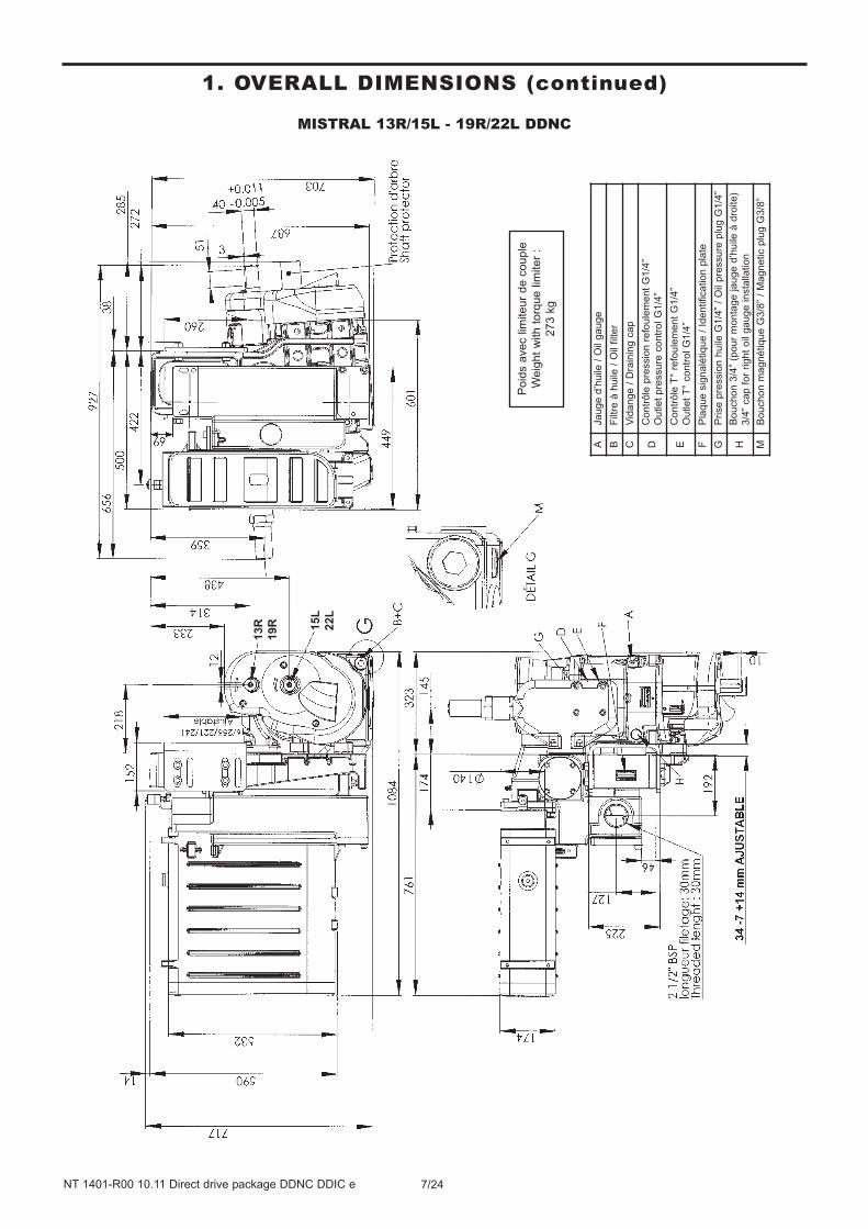
MISTRAL 13R/15L - 19R/22L DDNC
1. OVERALL DIMENSIONS (continued)
Poid
s a
vec lim
iteur
de c
ouple
Weig
ht
with t
orq
ue lim
iter
:
273 k
g
13R
19R 15L
22L
AJa
ug
e d
’hu
ile /
Oil
ga
ug
e
BF
iltre
à h
uile
/ O
il filte
r
CV
ida
ng
e /
Dra
inin
g c
ap
DC
on
trô
le p
ressio
n r
efo
ule
me
nt
G1
/4”
Ou
tle
t p
ressu
re c
on
tro
l G
1/4
”
EC
on
trô
le T
° re
fou
lem
en
t G
1/4
”
Ou
tle
t T
° co
ntr
ol G
1/4
”
FP
laq
ue
sig
na
létiq
ue
/ I
de
ntifica
tio
n p
late
GP
rise
pre
ssio
n h
uile
G1
/4”
/ O
il p
ressu
re p
lug
G1
/4”
HB
ou
ch
on
3/4
” (p
ou
r m
on
tag
e ja
ug
e d
’hu
ile à
dro
ite
)
3/4
” ca
p f
or
rig
ht
oil
ga
ug
e in
sta
llatio
n
MB
ou
ch
on
ma
gn
étiq
ue
G3
/8”
/ M
ag
ne
tic p
lug
G3
/8”

8/24NT 1401-R00 10.11 Direct drive package DDNC DDIC e
TYPHON II 20R - 30R DDNC
1. OVERALL DIMENSIONS (continued)
Poid
s a
vec lim
iteur
de c
ouple
Weig
ht
with t
orq
ue lim
iter
:
270 k
g
AJa
ug
e d
’hu
ile /
Oil
ga
ug
e
BF
iltre
à h
uile
/ O
il filte
r
CV
ida
ng
e /
Dra
inin
g c
ap
DC
on
trô
le p
ressio
n r
efo
ule
me
nt
G1
/4”
Ou
tle
t p
ressu
re c
on
tro
l G
1/4
”
EC
on
trô
le T
° re
fou
lem
en
t G
1/4
”
Ou
tle
t T
° co
ntr
ol G
1/4
”
FP
laq
ue
sig
na
létiq
ue
/ I
de
ntifica
tio
n p
late
GP
rise
pre
ssio
n h
uile
/ O
il p
ressu
re p
lug
HB
ou
ch
on
3/4
” (p
ou
r m
on
tag
e ja
ug
e d
’hu
ile à
dro
ite
)
3/4
” ca
p f
or
rig
ht
oil
ga
ug
e in
sta
llatio
n
JP
rise
vite
sse
G1
/4”
/ S
pe
ed
co
ntr
ol G
1/4
”
KC
on
trô
le p
ressio
n a
sp
ira
tio
n G
1/4
”
Inle
t p
ressu
re c
on
tro
l G
1/4
”
LC
on
trô
le T
° a
sp
ira
tio
n G
1/4
” /
Inle
t T
° co
ntr
ol G
1/4
”
MB
ou
ch
on
ma
gn
étiq
ue
G3
/8”
/ M
ag
ne
tic p
lug
G3
/8”

9/24NT 1401-R00 10.11 Direct drive package DDNC DDIC e
TYPHON II 13R/15L - 19R/22L DDNC
1. OVERALL DIMENSIONS (continued)
Poid
s a
vec lim
iteur
de c
ouple
Weig
ht
with t
orq
ue lim
iter
:
300 k
g
13R
19R
15L
22L
AJa
ug
e d
’hu
ile /
Oil
ga
ug
e
BF
iltre
à h
uile
/ O
il filte
r
CV
ida
ng
e /
Dra
inin
g c
ap
DC
on
trô
le p
ressio
n r
efo
ule
me
nt
G1
/4”
Ou
tle
t p
ressu
re c
on
tro
l G
1/4
”
EC
on
trô
le T
° re
fou
lem
en
t G
1/4
”
Ou
tle
t T
° co
ntr
ol G
1/4
”
FP
laq
ue
sig
na
létiq
ue
/ I
de
ntifica
tio
n p
late
GP
rise
pre
ssio
n h
uile
/ O
il p
ressu
re p
lug
HB
ou
ch
on
3/4
” (p
ou
r m
on
tag
e ja
ug
e d
’hu
ile à
dro
ite
)
3/4
” ca
p f
or
rig
ht
oil
ga
ug
e in
sta
llatio
n
JP
rise
vite
sse
G1
/4”
/ S
pe
ed
co
ntr
ol G
1/4
”
KC
on
trô
le p
ressio
n a
sp
ira
tio
n G
1/4
”
Inle
t p
ressu
re c
on
tro
l G
1/4
”
LC
on
trô
le T
° a
sp
ira
tio
n G
1/4
” /
Inle
t T
° co
ntr
ol G
1/4
”
MB
ou
ch
on
ma
gn
étiq
ue
G3
/8”
/ M
ag
ne
tic p
lug
G3
/8”

10/24NT 1401-R00 10.11 Direct drive package DDNC DDIC e
B600 20R - 30R DDIC
1. OVERALL DIMENSIONS (continued)
Poid
s a
vec lim
iteur
de c
ouple
Weig
ht
with t
orq
ue lim
iter
:
257 k
g
AJa
ug
e d
’hu
ile /
Oil
ga
ug
e
BF
iltre
à h
uile
/ O
il filte
r
CV
ida
ng
e /
Dra
inin
g c
ap
DC
on
trô
le p
ressio
n r
efo
ule
me
nt
G1
/4”
Ou
tle
t p
ressu
re c
on
tro
l G
1/4
”
EC
on
trô
le T
° re
fou
lem
en
t G
1/4
”
Ou
tle
t T
° co
ntr
ol G
1/4
”
FP
laq
ue
sig
na
létiq
ue
/ I
de
ntifica
tio
n p
late
GP
rise
pre
ssio
n h
uile
/ O
il p
ressu
re p
lug
HB
ou
ch
on
3/4
” (p
ou
r m
on
tag
e ja
ug
e d
’hu
ile à
dro
ite
)
3/4
” ca
p f
or
rig
ht
oil
ga
ug
e in
sta
llatio
n
JP
rise
vite
sse
G1
/4”
/ S
pe
ed
co
ntr
ol G
1/4
”
KC
on
trô
le p
ressio
n a
sp
ira
tio
n G
1/4
”
Inle
t p
ressu
re c
on
tro
l G
1/4
”
LC
on
trô
le T
° a
sp
ira
tio
n G
1/4
” /
Inle
t T
° co
ntr
ol G
1/4
”
MB
ou
ch
on
ma
gn
étiq
ue
G3
/8”
/ M
ag
ne
tic p
lug
G3
/8”
11/24NT 1401-R00 10.11 Direct drive package DDNC DDIC e
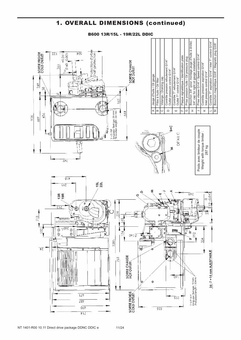
B600 13R/15L - 19R/22L DDIC
1. OVERALL DIMENSIONS (continued)
Poid
s a
vec lim
iteur
de c
ouple
Weig
ht
with t
orq
ue lim
iter
:
287 k
g
AJa
ug
e d
’hu
ile /
Oil
ga
ug
e
BF
iltre
à h
uile
/ O
il filte
r
CV
ida
ng
e /
Dra
inin
g c
ap
DC
on
trô
le p
ressio
n r
efo
ule
me
nt
G1
/4”
Ou
tle
t p
ressu
re c
on
tro
l G
1/4
”
EC
on
trô
le T
° re
fou
lem
en
t G
1/4
”
Ou
tle
t T
° co
ntr
ol G
1/4
”
FP
laq
ue
sig
na
létiq
ue
/ I
de
ntifica
tio
n p
late
GP
rise
pre
ssio
n h
uile
/ O
il p
ressu
re p
lug
HB
ou
ch
on
3/4
” (p
ou
r m
on
tag
e ja
ug
e d
’hu
ile à
dro
ite
)
3/4
” ca
p f
or
rig
ht
oil
ga
ug
e in
sta
llatio
n
JP
rise
vite
sse
G1
/4”
/ S
pe
ed
co
ntr
ol G
1/4
”
KC
on
trô
le p
ressio
n a
sp
ira
tio
n G
1/4
”
Inle
t p
ressu
re c
on
tro
l G
1/4
”
LC
on
trô
le T
° a
sp
ira
tio
n G
1/4
” /
Inle
t T
° co
ntr
ol G
1/4
”
MB
ou
ch
on
ma
gn
étiq
ue
G3
/8”
/ M
ag
ne
tic p
lug
G3
/8”
13R
19R
15L
22L

12/24NT 1401-R00 10.11 Direct drive package DDNC DDIC e
MISTRAL 20R - 30R DDIC
1. OVERALL DIMENSIONS (continued)
Poid
s a
vec lim
iteur
de c
ouple
Weig
ht
with t
orq
ue lim
iter
:
278 k
g
AJa
ug
e d
’hu
ile /
Oil
ga
ug
e
BF
iltre
à h
uile
/ O
il filte
r
CV
ida
ng
e /
Dra
inin
g c
ap
DC
on
trô
le p
ressio
n r
efo
ule
me
nt
G1
/4”
Ou
tle
t p
ressu
re c
on
tro
l G
1/4
”
EC
on
trô
le T
° re
fou
lem
en
t G
1/4
”
Ou
tle
t T
° co
ntr
ol G
1/4
”
FP
laq
ue
sig
na
létiq
ue
/ I
de
ntifica
tio
n p
late
GP
rise
pre
ssio
n h
uile
G1
/4”
/ O
il p
ressu
re p
lug
G1
/4”
HB
ou
ch
on
3/4
” (p
ou
r m
on
tag
e ja
ug
e d
’hu
ile à
dro
ite
)
3/4
” ca
p f
or
rig
ht
oil
ga
ug
e in
sta
llatio
n
MB
ou
ch
on
ma
gn
étiq
ue
G3
/8”
/ M
ag
ne
tic p
lug
G3
/8”
13/24NT 1401-R00 10.11 Direct drive package DDNC DDIC e
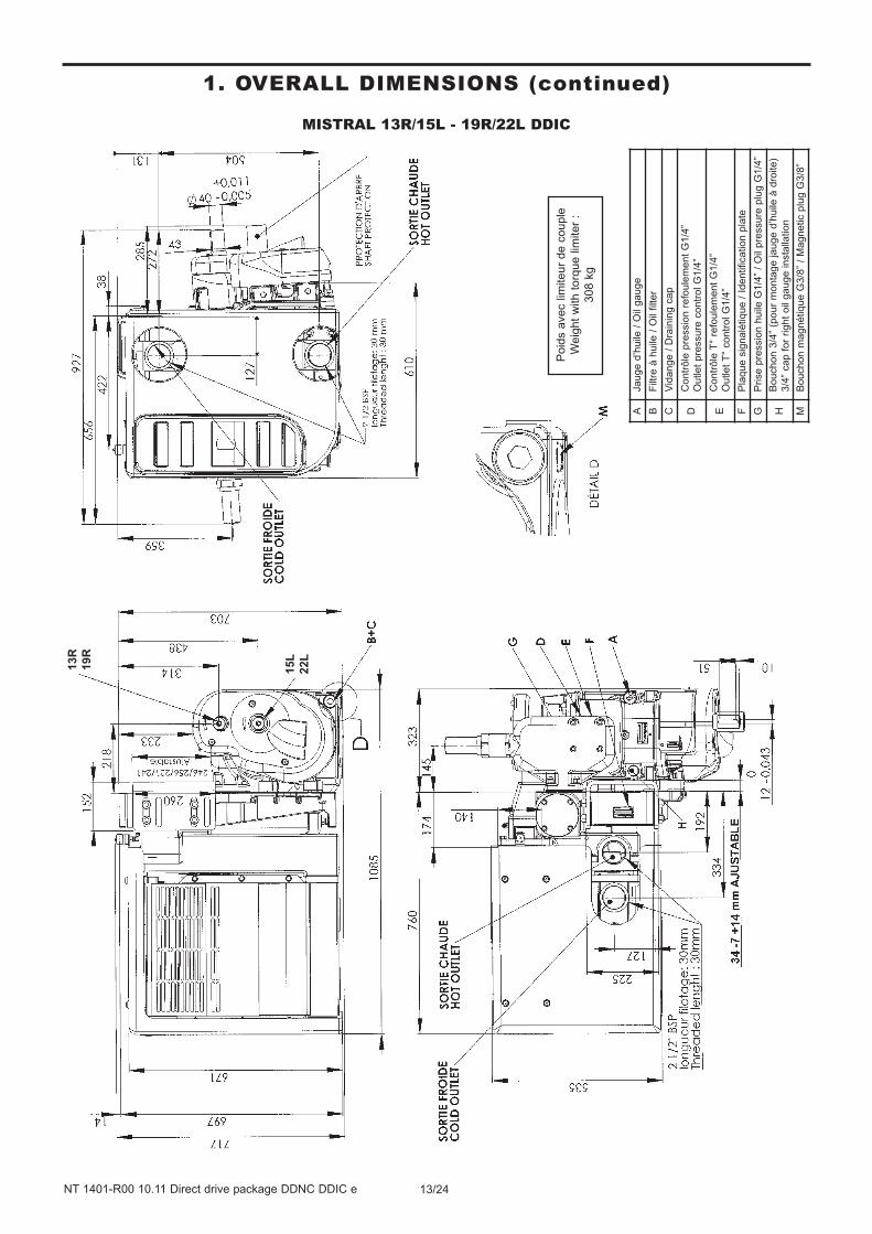
MISTRAL 13R/15L - 19R/22L DDIC
1. OVERALL DIMENSIONS (continued)
Poid
s a
vec lim
iteur
de c
ouple
Weig
ht
with t
orq
ue lim
iter
:
308 k
g
13R
19R
15L
22L
AJa
ug
e d
’hu
ile /
Oil
ga
ug
e
BF
iltre
à h
uile
/ O
il filte
r
CV
ida
ng
e /
Dra
inin
g c
ap
DC
on
trô
le p
ressio
n r
efo
ule
me
nt
G1
/4”
Ou
tle
t p
ressu
re c
on
tro
l G
1/4
”
EC
on
trô
le T
° re
fou
lem
en
t G
1/4
”
Ou
tle
t T
° co
ntr
ol G
1/4
”
FP
laq
ue
sig
na
létiq
ue
/ I
de
ntifica
tio
n p
late
GP
rise
pre
ssio
n h
uile
G1
/4”
/ O
il p
ressu
re p
lug
G1
/4”
HB
ou
ch
on
3/4
” (p
ou
r m
on
tag
e ja
ug
e d
’hu
ile à
dro
ite
)
3/4
” ca
p f
or
rig
ht
oil
ga
ug
e in
sta
llatio
n
MB
ou
ch
on
ma
gn
étiq
ue
G3
/8”
/ M
ag
ne
tic p
lug
G3
/8”

14/24NT 1401-R00 10.11 Direct drive package DDNC DDIC e
TYPHON II 20R - 30R DDIC
1. OVERALL DIMENSIONS (continued)
Poid
s a
vec lim
iteur
de c
ouple
Weig
ht
with t
orq
ue lim
iter
:
306 k
g
AJa
ug
e d
’hu
ile /
Oil
ga
ug
e
BF
iltre
à h
uile
/ O
il filte
r
CV
ida
ng
e /
Dra
inin
g c
ap
DC
on
trô
le p
ressio
n r
efo
ule
me
nt
G1
/4”
Ou
tle
t p
ressu
re c
on
tro
l G
1/4
”
EC
on
trô
le T
° re
fou
lem
en
t G
1/4
”
Ou
tle
t T
° co
ntr
ol G
1/4
”
FP
laq
ue
sig
na
létiq
ue
/ I
de
ntifica
tio
n p
late
GP
rise
pre
ssio
n h
uile
/ O
il p
ressu
re p
lug
HB
ou
ch
on
3/4
” (p
ou
r m
on
tag
e ja
ug
e d
’hu
ile à
dro
ite
)
3/4
” ca
p f
or
rig
ht
oil
ga
ug
e in
sta
llatio
n
JP
rise
vite
sse
G1
/4”
/ S
pe
ed
co
ntr
ol G
1/4
”
KC
on
trô
le p
ressio
n a
sp
ira
tio
n G
1/4
”
Inle
t p
ressu
re c
on
tro
l G
1/4
”
LC
on
trô
le T
° a
sp
ira
tio
n G
1/4
” /
Inle
t T
° co
ntr
ol G
1/4
”
MB
ou
ch
on
ma
gn
étiq
ue
G3
/8”
/ M
ag
ne
tic p
lug
G3
/8”

15/24NT 1401-R00 10.11 Direct drive package DDNC DDIC e
TYPHON II 13R/15L - 19R/22L DDIC
1. OVERALL DIMENSIONS (continued)
Poid
s a
vec lim
iteur
de c
ouple
Weig
ht
with t
orq
ue lim
iter
:
336 k
g
13R
19R
15L
22L
AJa
ug
e d
’hu
ile /
Oil
ga
ug
e
BF
iltre
à h
uile
/ O
il filte
r
CV
ida
ng
e /
Dra
inin
g c
ap
DC
on
trô
le p
ressio
n r
efo
ule
me
nt
G1
/4”
Ou
tle
t p
ressu
re c
on
tro
l G
1/4
”
EC
on
trô
le T
° re
fou
lem
en
t G
1/4
”
Ou
tle
t T
° co
ntr
ol G
1/4
”
FP
laq
ue
sig
na
létiq
ue
/ I
de
ntifica
tio
n p
late
GP
rise
pre
ssio
n h
uile
/ O
il p
ressu
re p
lug
HB
ou
ch
on
3/4
” (p
ou
r m
on
tag
e ja
ug
e d
’hu
ile à
dro
ite
)
3/4
” ca
p f
or
rig
ht
oil
ga
ug
e in
sta
llatio
n
JP
rise
vite
sse
G1
/4”
/ S
pe
ed
co
ntr
ol G
1/4
”
KC
on
trô
le p
ressio
n a
sp
ira
tio
n G
1/4
”
Inle
t p
ressu
re c
on
tro
l G
1/4
”
LC
on
trô
le T
° a
sp
ira
tio
n G
1/4
” /
Inle
t T
° co
ntr
ol G
1/4
”
MB
ou
ch
on
ma
gn
étiq
ue
G3
/8”
/ M
ag
ne
tic p
lug
G3
/8”

The screws used to :• hold the compressor in place
• mount the filter flange
• mount the discharge flange
must be at least quality 12-9.
During the assembly, watch that no foreign body penetrates
into the compressor. The piping of inhalation and expulsion
must be perfectly clean. Any foreign body risks to damage
seriously the compressor.
The presence of foreign bodies in the compressor inlet
channel is susceptible of leading to serious property
damage or serious injuries.
2.1 Mounting locationThe compressor must be installed in a location where it is
easily accessible. In particular, make sure that the oil
filling plug, oil magnetic plugs and the filter are accessible.
The clogging indicator must remain visible to the operator.
Choose a location where the compressor is relatively
protected from gravel projections and road spray as well
as exhaust fumes and engine heat.
The compressor is mounted on the chair at an angle of
4°. If the chair is mounted vertically, it can be used to
adapt to most movements, in other words those which
have a gradient of between 3 and 5° inclusive.
To prevent potential interferences between the package
and the truck accessories (mudflap, tank, … ) a mini-
mum distance of 5 cm between the package and these
accessories must be respected.
To benefit fully from the cooling performance of DDIC
packages, a minimum distance of 10cm must be respec-
ted between the right side of the package and any
accessory forming an obstacle to air flow (tank, … ).
In the same way, a minimum distance of 5 cm must be
respected between all accessories located in the chassis
(PTO, universal joint, ...) and the compressor package.
2.2 Mounting procedure
2.2.1 Package handling procedure
Compressors are packaged and fixed onto a pallet. To
move and install the package for the first time, the pac-
kage should be carried on the pallet.
For maintenance operations, the package should be fas-
tened onto a pallet such that the chair is vertical. The
areas set aside for fastening the package are the com-
pressor, silencer and inlet filter, as shown in the picture
below.Standard package
angle : 4°
Variable angle from PTO to
PTO. 3° to 5° are acceptable
while chair is vertical.
Those areas are acceptable to sup-
port the package. Compressor and
chair support should be favored.
5 cm clearance to
avoid any contact
10 cm clearance to
optimize package
outlet temperature
CAUTION
16/24NT 1401-R00 10.11 Direct drive package DDNC DDIC e
2. INSTALLATION

17/24NT 1401-R00 10.11 Direct drive package DDNC DDIC e
2. INSTALLATION (continued)
2.2.2 Package installation procedure
The compressor package is delivered with a special
assembly tool. This U comes mounted on the chair. The
U is not symmetrical, so that the installer has more room
to move when choosing the vertical position of the pac-
kage.
We propose the following assembly procedure:
• Bring the compressor package to the side of the truck
using a transpallet or any other suitable equipment.
• Determine the position of the package on the truck as
close as possible to its final position.
• Check the universal joint angles and how parallel the
compressor shaft and the PTO shaft are
• Mark on the U the positions of the holes necessary for
assembly.
• Remove the package from the truck
• Pierce the U, deburr and clean. To make sure that you
do not make the part fragile keep a minimum axle
spread distance of 40 mm between 2 holes.
• Use 6 screws Ø 14 mm minimum.
• Mount the U on the truck
• Bring the package to the truck
• Mount the package on the U with a minimum of 8 fixing
points (4 on each side)
• Remove the pallet and package
• Check the universal joint angles and how parallel the
compressor shaft and the PTO shaft are
• Mount the universal joint
• Perform an operating test on the compressor
• Check with a manometer the pressure at which the
valve starts to open
2.3 At succionIt must be installed in such a way that the temperature of
the air sucked in is equivalent to 5°C either side of
ambient temperature.
Any side protection barriers must be removed EACH
time the compressor is used yo allow air to reach the
compressor inlet freely, and move around the cooling cir-
cuit.
The installer must check whether there are such protec-
tive barriers and that they may be manipulated easily by
the driver. It may be desirable to install a system preven-
ting the operation of the PTO if the protection is not
removed, to guarantee that the compressor operates
under satisfactory conditions.
To prevent the filters from clogging prematurely, the air suc-
ked in must be free of smoke and road dust.
A minimum distance of 300 mm must be left free in front
of the filters for their extraction and replacement.
2.3.1 Standard suction
If using a standard package, no precautions need be
taken wjen assembling the package.
2.3.2 Chimney suction
If using a chimney package, it will be delivered with a fil-
ter plugging plate instead of an in the location of the nor-
mal air feed plate.
If this is the case, the air must be fed to the compressor
from the rear of the filter box, on the boss, of diameter
140cm for the purpose.
NB The boss is not delivered pierced. The installer is
responsible for piercing the aluminium on the inner pas-
sage assembly or cutting the edge of the boss. Tp pre-
vent spillages during this operation from penetrating the
compressor inlet channel, it is important to leave the fil-
ters in place during the assembly operation. The filter
box will be cleaned and the filters will be replaced befo-
re the compressor is put into service.
The installer is also responsible for mounting the filter
clogging indicator somewhere visible to the truck driver
under normal use of the compressor package.
MACHINING RESIDUE IN THE INLET PIPE, OR IN
THE COMPRESSION CHAMBER IS GROUND
FOR WARRANTY LOSS.
Standard
version
The installor must
move the clogging
indicator
Chimney version,
the front suction
is clogged
The boss is to be cut and
drilled to supply the chimney
air to the compressor.
The openings are not
symetrical versus the U
upper and lower sides

2.4 Check relief / Safety valveDDNC and DDIC packages include a safety valve and a
check valve.
The check valve is fpr preventing the return of particles
from the tanker to the compressor, especially when the
compressor is switched off, when the tanker is still pres-
surised.
The valve was adjusted prior to delivery. This adjustment
is leaded.
Any valve manipulation will void the guarantee. Only
MOUVEX personnel or authorised service centres are
qualified to adjust the safety valves.
The maximum valve setting is 2.5 bar, but it must take
into account the rotating speed range specified in the
compressor instructions.
2.5 Drive
2.5.1 Speed range
In order to comply with the machine directive, the rota-
ting parts of the compressor package (shafts, torque
limiter, universal joint, PTO … ) must not be accessible
to the user or the driver under normal conditions. If
necessary, it is the installer’s responsibility to fit the
necessary protection for preventing any damage to
equipment or physical injury.
MOUVEX cannot be held responsible for consequences
due to the absence of such protection on the final instal-
lation.
The compressor may be operated directly by a universal
joint shaft, with or without a multiplier.
The selection of the drive mode will take into account :
• The compressor mounting configuration
• The driving shaft rotation direction
• The expected power requirement for the given applica-
tion
• The acceptable rpm range for the driving equipment
• The acceptable rpm range for the compressor.
The use of compressors outside of their operating speed
range can lead to property damage or serious injuries.
See Compressor instructions for more details.
IMPORTANT :
Any system providing for a compressor being driven
by a thermal motor must include a system making it
possible to disengage the compressor at startup and
stop of the motor.
In all cases, the drive must make it possible :
• To maintain the compressor rotation speed during load
variations (pressure variations) .
• Not to subject the compressor to sudden or insuffi-
cient starts.
2.5.2 PTO Shaft drive
It is mandatory to comply with the following instructions :
• The shaft must be dynamically balanced.
• Its length and its inclination must be as small as pos-
sible, see table
• The drive shaft slides perfectly well during rotation.
• The jaws of the universal joints are parallel.
• Coupling flanges show no eccentricity nor warping of
the bearing surface.
• The angle formed by the universal joint and the drive
shaft must not exceed 15°.
• The compressor shaft must be parallel to that of the
drive shaft.
• The universal joint angle, as defined below, must ne
minimised.
DDNC and DDIC packages incorporate a compressor
gradient of 4° in relation to the horizontal. This gradient
allows the recovery of the most recent PTO angles on
current trucks. If your PTO angle is between 3 and 5°
inclusive, you can install the chair vertically and respect
operating recommendations.
If this is not the case, you should gently slope the chair
to bring the angle between the compressor operating
shaft and the PTO below 1°.
A = H² + W² L
A Universal joint angle
0,017 1°
VERY GOOD0,035 2°
0,052 3°
0,070 4°
0,087 5°
0,105 6°
GOOD0,125 7°
0,141 8°
0,158 9°
0,176 10°
0,194 11°
LIMIT
VALUES
0,213 12°
0,231 13°
0,249 14°
0,268 15°
CAUTION
THE USE OF A PACKAGE AT PRESSURES
GREATER THAN THOSE RECOMMENDED
MAY CAUSE DAMAGE TO EQUIPMENT OR
SERIOUS INJURY.
WARNING
Hazardous pressure
can cause
personal injury
or property damage.
18/24NT 1401-R00 10.11 Direct drive package DDNC DDIC e
2. INSTALLATION (continued)

It is possible to equip packages with a multiplier to lesse-
jn the universal joint angle. Refer to the compressor
instructions for further information.
To protect the P.T.O in the event of compressor stalling,
it is necessary to install a torque limiter.
The MOUVEX company shall not be held responsible for
damage resulting from such stalling if this stalling is
caused by wrong manipulation with the compressor or if
no or not the right torque limiter is installed.
The torque limiter will be installed on the compressor
shaft, as illustrated in the photo below.
DDNC/DDIC packages may be ordered with torque limi-
ters mounted. Refer to Instructions 1401-B00 TORQUE
LIMITER - SCREW COMPRESSORS.
If the greasing instructions for the universal joint are
not respected, this can lead to ruptures of this uni-
versal joint, as well as property damage and serious
injuries.
2.5.3 Installation of channelling
Channelling connected to the package must be desi-
gned in accordance with regulations to prevent prematu-
re breakdowns on the installation.
In particular, MOUVEX recommends taking the following
precautions:
• Channelling must be supported so as to prevent then
from mechanically loading the inlets and outlets on
the compressor package.
• Inlet and discharge channelling must have a diameter
at least equal to that of inlet and discharge connec-
tions on the compressor package.
• At the inlet, you should limit sources of load loss
(elbows, valves, lengths of channelling…).
2.6 Electric circuitThe DDNC packages do not require any power supply to
operate.
The DDIC packages require a power supply to run the
cooler fan.
2.6.1 Version with the monitoring and connection
box for the management of the fan motors
To prevent consumption of electricity when the compres-
sor is not running, a relative pressure switch compares
the pressure downstream with ambient pressure. If the
downstream compressor pressure is more than 80 mbar
greater than ambient pressure, the package cooler fan
will start.
The fans start one after the other at low speed and then
switch simultaneously to high speed after few seconds.
Under most usage conditions (package outlet linked to a
tanker … ), the fan will start almost simultaneously with
the starting of the compressor.
If the user needs non-cooled air, he must connect to one
of the hot outlets of the package. No system can be used
to adjust the cooling power delivered by the fan.
2.6.1.1 Electrical installation diagram
2.6.1.2 Connection procedure
Warning : The current source must be cut before any
intervention in the electrical circuit to prevent any dam-
age to equipment or physical injury.
Before the electrical circuit is installed, the fuses should be
removed. These must not be put back until the package is
fully installed. See procedure § 2.6.3 Fuse replacement.
The fuses must always be tested before they are installed.
The power supply must be protected with a 40 A fuse
(supplied) on the equipment and on the power supply.
F1
F2
F1 = F2 = 20 A
Bro
wn
Blu
e
Compressor
Torque limiter
CAUTION
19/24NT 1401-R00 10.11 Direct drive package DDNC DDIC e
2. INSTALLATION (continued)

20/24NT 1401-R00 10.11 Direct drive package DDNC DDIC e
2. INSTALLATION (continued)
The power cable must be installed :
• Either directly onto the battery,
• Or connected to a line available on the truck with a
capacity of 40 A.
The 2 wires must be separated from the main cable by
10 cm and 5 mm must be stripped.
The electric cable linking the compressor package to the
power supply must be correctly supported to prevent
wear through friction.
When it is first used, you should check that the air is
blown by the fan through the cooler. If the air is sucked
in by the fan through the cooler, have another look at the
cabling.
CAUTION :
Not respecting the direction of air circulation will lead to
significant loss of cooler performance and fan reliability
problems.
2.6.2 Version without the monitoring and
connection box for the management of the
fan motors
2.6.2.1 Electrical cabling
+24v Marron
0v Bleu
2.6.2.2 Connection procedure
Warning : The current source must be cut before any
intervention in the electrical circuit to prevent any dama-
ge to equipment or physical injury.
The power supply for the package must be protected
with a 40 A (supplied) fuse on the equipment and on the
power supply.
The electrical cable linking the compressor package to
the power supply must be correctly supported to prevent
its wear through friction, which could make the equip-
ment live or cause unwanted microcuts.
The installer is responsible for supplying this electric line
when the compressor is in use and switching it off when
the compressor is not required.
To provide with power the fans use a relay able to switch
70A. It could be controlled by a manual switch or auto-
matic device that uses the command signal of the
control drive (pneumatic or electric).
Turning off the fan while the compressor is running can
cause damage to equipment or physical injury (failure of
the fan or accessories on the cooled outlet …).
MOUVEX will not accept any return under warranty for
fan failure on packages supplied without box.
When it is first used, you should check that the air is
blown by the fan through the cooler. If the air is sucked
in by the fan through the cooler, have another look at the
cabling.
CAUTION :
Not respecting the direction of air circulation will lead to
significant loss of cooler performance and fan reliability
problems.
2.6.3 Fuse replacement
The fuses are accessible by unscrewing the fuse holder
cap fitted on the box (see picture).
Fuses are 20 A temporized models.
Reference : ceramic mini fuse HPC time-delay fuse,
Ø 6,3 mm, lenght 32 mm, RS 70-065-65/20ARS.
A replacement fuse is supplied in a bag with each package.
REMINDER :
• Opening the electric box damages the waterproof ness
and voids any warranty.
• The replacement of the electric box requires replacing
also the electric cables. The electric box must never be
opened.
Airflow
direction
Airflow
direction

2.7 InstrumentationThe package is supplied with an inlet filter clogging indi-
cator.
Any use of the compressor package when the indicator
is showing excessive clogging will cause damage to
equipment or physical injury.
Once the filters have been replaced, the clogging indicator
mat be reset to zero merely by rotating its cap.
2.8 Chair modificationNo chair modification operation is permitted :
• Piercings
• Assembly operations
• Cutoff
risk of loss of MOUVEX warranty on the equipment.
21/24NT 1401-R00 10.11 Direct drive package DDNC DDIC e
2. INSTALLATION (continued)
3.1 Maintenance schedules
See the compressor instructions for the mainte-
nance programme.
3.2 Air filter replacement procedureCheck weekly the clogging indicator. When it turns red,
replace the filter cartridge.
Before installing a new cartridge, clean the internal part
of the filter housing with a clean damp cloth.
The presence of foreign bodies in the compressor
inlet channel is susceptible of leading to serious
property damage or serious injuries.
3.3 Cartridge replacement procedure• Remove the wheel holding the filter cover
• Remove the filter cover
• Remove the screws holding the 3 round cartridges in
place
• Remove the 3 round cartridges
• Throw away the old round cartridges
• Clean the area around the cartridge seal with a rag
• Place the cartridges on the supports in the following
order :
- Upper cartridge
- Lower cartridge
- Central cartridge
• Screw up the cartridges keeping the supports in a hori-
zontal, centred position in relation to the sides of the fil-
ter box. The screwing will be done in the same order as
that of the cartridge mounting.
• Replace the filter cover.
• By hand, rescrew the end wheel.
3.4 Drive train inspection Periodically check that there is no play in the jaws and
PTO cross pieces, turning the universal joint manually in
one direction then in the other direction.
3.5 Check valve and relief valve inspectionSee Instructions 1401-E00 SCREW COMPRESSOR
CHECK AND RELIEF VALVE.
3.6 Warranty claimsThe following part are considered as wear part :
• Inlet filter cartridge
• Compressor oil
No failure connected with wear part damage will be
accepted under warranty conditions.
The following situations will void warranty for all compo-
nents of the package :
• Tampering with the setting of the relief valve.
• Presence of foreign material inside the compressor
body.
• Traces of damage representative of abnormal use of
the package.
• Use of non genuine parts.
• If the compressor is repaired by a repairer who is not
a MOUVEX-approved repairer.
• Construction of the package not validated by our
Design Office.
• Use of an oil other than BSC for a 13R/15L and
19R/22L compressor.
Before returning your equipment to the factory, you must
first obtain an Equipment return approval (RMA) from
our After Sales Department.
A Compressors form information shall be filled by the
installer or distributor and send to MOUVEX in order to
claim for a warranty.
CAUTION
3. MAINTENANCE

22/24NT 1401-R00 10.11 Direct drive package DDNC DDIC e
The equipment must be systematically stored in an area shel-
tered from bad weather.
The equipment must bear its original protective components
until it is installed in its final application.
If installation is interrupted, put back in place the original pro-
tective components or equivalent components.
5. STORAGE CONDITIONS
Problem Possible origin Possible solution
Too much pressure drop. To check pipes diameter.
Relief valve damaged. To check the opening point. 1. Pressure issue
No return valve damaged. To check the proper operating of the No return valve.
Wrong Compressor speed. To adjust the speed by taking care of the range allowed. 2. Flow rate issue
Relief valve damaged. To check the opening point.
Air filter clogged. To clean the cartridge or to replace it.
Air pressure too much high. To see problems 1. / 2.
Outside temperature too much high. To respect the maximum external temperature allowed.
Lack of oil. To check the oil level.
3. Abnormal high temperature
Compressor speed too much low. To adjust the speed by taking care of the range allowed.
Air filter clogged. To clean the cartridge or to replace it. 4. Inlet pressure drop > 75 mbar (Clogging indicator red)
Air inlet hose folded. To check the air inlet hose.
Torque limiter damaged. To replace the torque limiter. 5. Compressor doesn’t operate
Transmission damaged. To consult your Service point.
Screw Compressor damaged. To consult your Service point.
Clutch operates too much fast. To consult your Truck dealer. 6. Torque limiter damaged
Oil too much viscous. To be in compliance with the MOUVEX Instructions.
Too much oil. To check the oil level. 7. Oil leak
Oil breather clogged. To clean the oil breather.
Wrong motor speed. To increase the speed by taking care of the range allowed.
Transmission damaged. To check the driving shaft. 8. Vibrations
Lack of rigidity of the chassis. To be in compliance with the Truck Manufacturer Instructions.
4. TROUBLESHOOTING
CAUTION :
OBSERVE ALL SAFETY WARNINGS CONTAINED IN THIS MANUAL.
The operator should remain nearby the equipment throughout
the use to ensure the proper functioning of the system.
6. USE
The compressor must be scrapped in compliance with the
regulations in force.
During this operation, particular care must be paid to the drai-
nage stages of the compressor.
7. SCRAPPING

23/24NT 1401-R00 10.11 Direct drive package DDNC DDIC e
8. COMPRESSORS FORM INFORMATION
MOUVEX After Sales Department Tel : (33) 3 86 49 86 03 Date :Z.I. La Plaine des Isles Fax : (33) 3 86 49 86 48 Followed by :89000 AUXERRE - France File :
A – Name and address of user
Person to contact : Phone Nr :B – Name and address of installator
Person to contact : Phone Nr :
C - Material's serial number D - Starting up date
Running time estimation
PTO flanged Propshaft drive system (direct PTO drive) Compressor's speed30R 20R 19R 13R 22L 15L Operating pressure12R 10L Torque limiter Pressure relief valve setting (value) Belt drive system PTO ratio : Package air cooler Package RTI Product transfered
Air connection on truck chimney Direct air connectionFlexible pipe between filter and compressorInox pipe between filter and compressor
Blocking Leakage Noise, vibration Other
I - Has the machine been replaced by a new one ? If yes which is the serial numberJ - Has the machine been replaced by a renoved one ? If yes which is the serial number
COMPRESSORS
FORM INFORMATION
FORM
RMA / YY / NNN
SAV-002-05.2010
In order to properly deal with the return material, please fill in this form.
E - Installation details F - Operating parameters
Motor speed (tachometer) at the time of the incident
Please send us back this completed form by fax or E mail as quick as possible.
Other (electric, thermic or hydraulic motor)
G - Suction conditions
H - DESCRIPTION OF THE FAILURE
K - Remarks and comments of the user about the problem :
Before any material return, it is required to get an authorization from MOUVEX.

24/24NT 1401-R00 10.11 Direct drive package DDNC DDIC e
CUM 220103 FORM-QUA-18-4
CERTIFICATE OF CONFORMITY
Mouvex, ZI La Plaine des Isles - Rue des Caillottes - 89000 Auxerre France, declares the following equipment :
Set-up : Pump / Compressor « bare-shaft » Pumping Unit / Compressor Unit
Type : Eccentric Disc Pump Vanes Pump Lobes Pump
Peristaltic Pump Centrifugal Pump Other Pump
Screws compressor Vanes compressor Hydraulic cooler
Designation : s/n° :
According to the specifications recorded in the file N° : _
is in conformity with the provisions of the following Directive :
« MACHINES » Directive 2006/42/EEC as transposed by the national legislation, concerning safety equipments and arrangements relative to mechanical and electric risks applicable to rotative machines.
NF EN 809:2009 NF EN 1672-2:2009 NF EN ISO 13857:2008 NF EN 12162:2009
And with the following marking : II2 G c IIB-T4 Max T° Flow = 80°C
is in conformity with the provisions of the following Directive :
« ATEX » Directive 94/9/EC (23 march 1994) as transposed by the national legislation, concerning equipment intended to be used in explosive atmospheres. Conformity obtained by application of the standards :
NF EN 1127-1:1997 NF EN 13463-1:2009 NF EN 13463-5:2009
ATEX Certification delivered by INERIS, Notified Body (INERIS - Parc Technologique Alata – 60550 Verneuil-en-Halatte - France).
The equipment indicated above must be used according to the foreseen use by its design and its manu-facturing, and according to the current standards. We, undersigned, declare that the concerned equipment is in conformity with the Directives listed above and in the applicable standards in force. For Mouvex SAS Company. Date : _______________
Quality Manager
MOUVEX sas : Z.I La Plaine des Isles – 2, rue des Caillottes - 89000 AUXERRE – France – SAS au capital de 8 496 855 € Tél : (33) 3.86.49.86.30 – Fax : (33) 3.86.46.42.10 – RCS AUXERRE 389 236 548 – APE 291 B – FR 85 389 236 548
www.mouvex.com
9. CERTIFICATE OF CONFORMITY


