

National Aeronautics and Space
Administration
www.nasa.gov
Deformed Shape and Stress Reconstruction in Plate and Shell Structures Undergoing Large Displacements: Application of Inverse Finite Element Method using Fiber-Bragg-Grating Strains
A. Tessler, J. Spangler, M.Gherlone, M. Mattone, and M. Di Sciuva NASA Langley Research Center, U.S.A. & Politecnico di Torino, Italy
WCCM 2012 Sao Paulo, Brazil (8-13 July 2012)
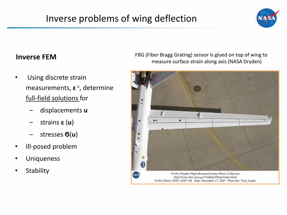
Inverse problems of wing deflection
FBG (Fiber Bragg Grating) sensor is glued on top of wing to measure surface strain along axis (NASA Dryden)
• Using discrete strain
measurements, ɛ ɛ, determine
full-field solutions for
‒ displacements u
‒ strains ɛ (u)
‒ stresses Ϭ(u)
• Ill-posed problem
• Uniqueness
• Stability
Inverse FEM

Variational Formulation based on First-Order Shear Deformation Theory (Mindlin)

Kinematic Assumptions of First-Order Shear Deformation Theory
• Deformations
– Membrane
– Bending
– Transverse shear
( , ) ( ) ( )
( , ) ( ) ( )
( ) ( )
x y
y x
z
u z u z
u z v z
u w
x x x
x x x
x x
( , ) (strain-measurement directions)
[ , ] (thickness coordinate)
x y
z t t
x
2t
z, w
y, v y
x
x, u
4
Strain rosettes or FBG fiber along x direction
• Displacement components
Top-surface measured strains
Bottom-surface measured strains
xx
yy
xy
xx
yy
xy
2t
z
Reference frame (aligned with strain-measurement directions)

Strains and Section Strains
1 4
2 5
3 6
xx
yy
xy
z
5
• Section strains
1
2
3
0 0 0 0
0 0 0 0
0 0 0
x
m
y
xy x
y
u
v
w
e u L u
4
5
6
0 0 0 0
0 0 0 0
0 0 0
x
b
y
xx y
y
u
v
w
k u L u
3 membrane section strains
3 bending section strains
7
8
0 0 0 1
0 0 1 0
x s
y
x
y
u
v
w
g u L u
• Inplane strains (=6) • Transverse-shear strains (=2)
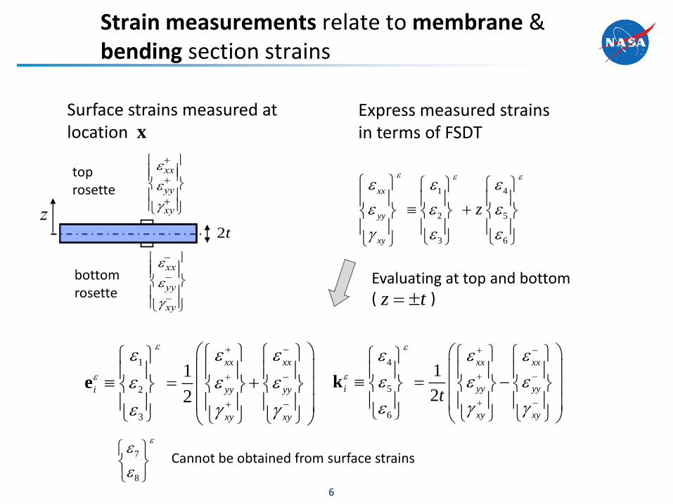
Strain measurements relate to membrane & bending section strains
4
5
6
1
2
xx xx
i yy yy
xy xy
t
k
1
2
3
1
2
xx xx
i yy yy
xy xy
e
top rosette
bottom rosette
xx
yy
xy
xx
yy
xy
2t
z
1 4
2 5
3 6
xx
yy
xy
z
Express measured strains in terms of FSDT
Evaluating at top and bottom ( )
Surface strains measured at location
z t
6
x
7
8
Cannot be obtained from surface strains
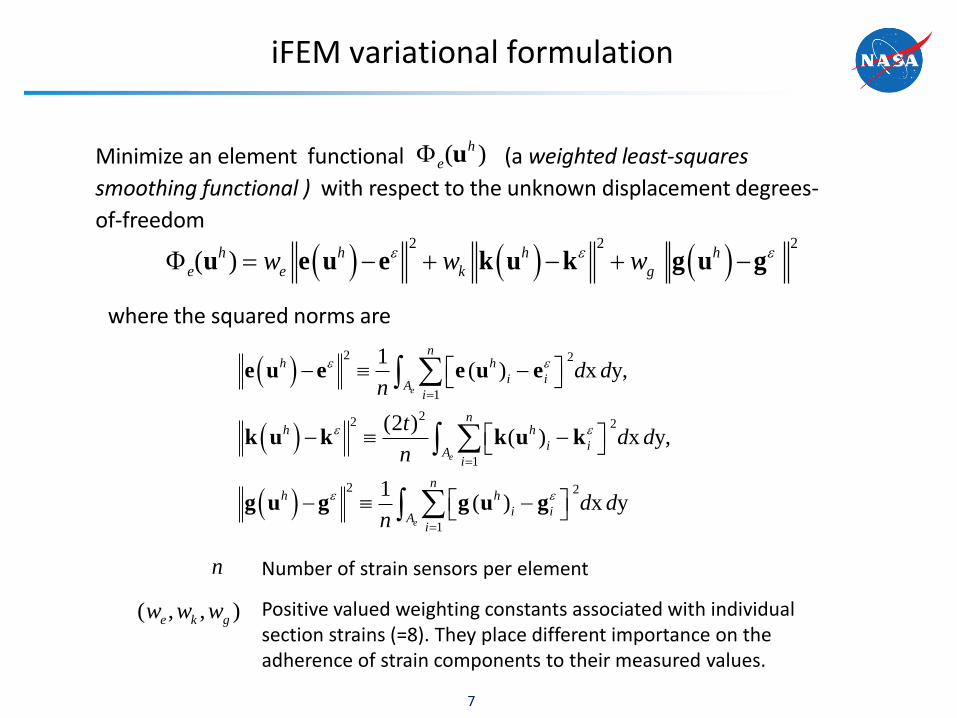
iFEM variational formulation
Minimize an element functional (a weighted least-squares
smoothing functional ) with respect to the unknown displacement degrees-
of-freedom
7
2 2 2
( )h h h h
e e k gw w w u e u e k u k g u g
where the squared norms are
2 2
1
22 2
1
2 2
1
1( ) x y,
(2 )( ) x y,
1( ) x y
e
e
e
nh h
i iA
i
nh h
i iA
i
nh h
i iA
i
d dn
td d
n
d dn
e u e e u e
k u k k u k
g u g g u g
Positive valued weighting constants associated with individual section strains (=8). They place different importance on the adherence of strain components to their measured values.
( , , )e k gw w w
n Number of strain sensors per element
( )h
e u

• Variational statement
iFEM matrix equations
Symmetric, positive definite matrix
dofu
( )iK x
Nodal displacement vector
( )f εRHS vector, function of measured strain values
1dof
( ) 0N
h
e
e
u
u
dof K u f
• Linear Eqs (displ. B.S.’s prescribed)
• iFEM integrates and smoothes strain data
• Higher accuracy than forward FEM
1dof
u K f
• Displacement solution

iFEM’s selective, element-level (local) regularization
1. An element is missing measured transverse-shear section strains
(standard case); Let
9
2
2( ) x y ( ; 1)e
h h
g e kA
d d w w w g u g u
2. An element is missing all measured section strains (in addition to (1))
22
22 2
( ) x y ( )
(2 ) ( ) x y ( )
e
e
h h
eA
h h
kA
d d w
t d d w
e u e u
k u k u
3. An element is missing some measured-strain components
‒ apply forms (2) to the missing components only
Important special cases
410 (small positive constant)

Simple and efficient inverse-shell element: iMIN3
• Anisoparametric interpolations (Tessler-Hughes, CMAME 1985)
, , , : linear shape functions
: quadratic
x yu v
w
10
, ( ) : constant
: linear
h h
h
e u k u
g u
• Section-strain fields
• 3 nodes, 5 or 6 dof/node
( , , )
[ , ]
x y z
z t t
x
2t
z, w
y, v y
x
x, u
h
, , , , : 5 dof/plate
, , , , , : 6 dof/shell
x y
x y z
u v w
u v w
Demonstration problem
11
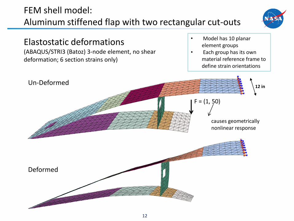
FEM shell model: Aluminum stiffened flap with two rectangular cut-outs
12
F = (1, 50)
Un-Deformed
Deformed
Elastostatic deformations (ABAQUS/STRI3 (Batoz) 3-node element, no shear deformation; 6 section strains only)
causes geometrically nonlinear response
12 in
• Model has 10 planar element groups
• Each group has its own material reference frame to define strain orientations

3 iFEM modeling and stabilization schemes
13
Model A: Six FEM section strains are mapped onto all iFEM elements • One-to-one (high-fidelity) • All elements have strain data but no
shear strain measurements
Model B: Six FEM section strains are mapped onto perimeter iFEM elements • Simulates tri-axial strain rosettes
along the perimeter • Interior elements have no strain
data including the stiffener (local regularization)
Model C: Two FEM section strains (axial) are mapped onto perimeter iFEM elements • Simulates linear strain gauges or
FBG strain sensors • Incomplete strain data • Interior elements have no strain
data including the stiffener (local regularization)
Axial strain measurements only in perimeter elements
Tri-axial strain measurements in perimeter (red) elements
Tri-axial strain measurements in every element

Linear problem: % error in reconstructed displacement, uz
14
Model A: Six FEM section strains are mapped onto all iFEM elements
Model B: Six FEM section strains are mapped only onto perimeter iFEM elements
Model C: Two FEM section strains (axial) are mapped only onto perimeter iFEM elements
Ref i Est i
Max
Ref
u u% Error (u ) =
u100z
zz
z
0.45%
0.70%
1.1%

Linear problem: Deviations in uz
15
iFEM 0% noise 5% noise model in strains in strains A 1.00000 0.99998 B 0.99999 0.99998 C 0.99998 0.99985
Pearson correlation, r
iFEM 0% noise 5% noise model in strains in strains A 0.00017 0.00096 B 0.00020 0.00074 C 0.00035 0.00098
RMS
iFEM 0% noise 5% noise model in strains in strains A 0.1951 1.0505 B 0.1934 0.8353 C 0.3575 1.0769
Mean % error
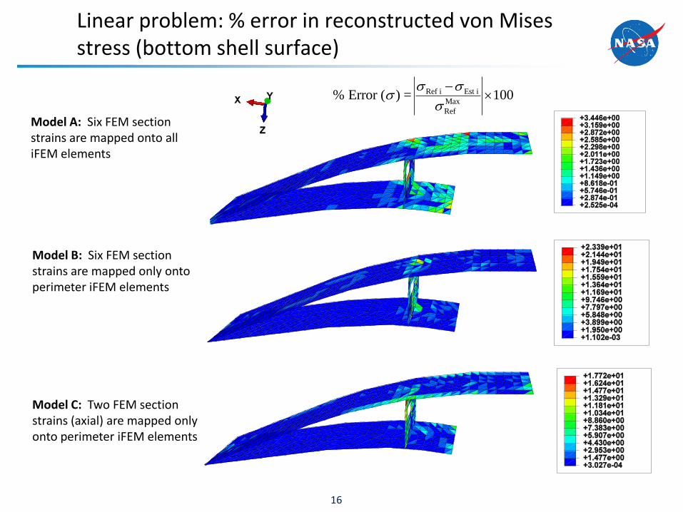
Linear problem: % error in reconstructed von Mises stress (bottom shell surface)
16
Model A: Six FEM section strains are mapped onto all iFEM elements
Model B: Six FEM section strains are mapped only onto perimeter iFEM elements
Model C: Two FEM section strains (axial) are mapped only onto perimeter iFEM elements
Ref i Est i
Max
Ref
% Error ( ) = 100

Linear problem: Deviations in von Mises stress
17
iFEM 0% noise 5% noise model in strains in strains A 0.9994 0.9993 B 0.9842 0.9844 C 0.9903 0.9896
Pearson correlation, r
iFEM 0% noise 5% noise model in strains in strains A 4.0149 5.72724 B 21.9314 23.4736 C 15.7996 16.9735
RMS
N
Ref i Ref EST i Esti 1
N N2 2
Ref i Ref Est i Esti 1 i 1
( )r
( )
2
REF i EST i1σ σ
N
iRMSN
Ref i Est i
M x
ef1 a
R
σ σ
σ
1100
N
iN
• Mean % error
• Pearson correlation, r
• Root-Mean-Square error
iFEM 0% noise 5% noise model in strains in strains A 0.3786 0.5553 B 1.6796 1.8404 C 1.3501 1.5133
Mean % error

iFEM incremental algorithm for nonlinear deformations
• Use Nonlinear FEM as a virtual experiment (Lagrangean reference
frame)
– At each load increment of NL-FEM, compute the incremental section
strains (6 components) that represent measured strain increments
– Perform iFEM analysis using the strain increments to obtain the
displacements and rotations
– Update the geometry of iFEM mesh due to deformation using iFEM
determined displacements, i.e., x1=x0+u1
– Perform iFEM using the strain increments of the next load increment, and
update the geometry for the next step x2=x1+u2
18

Nonlinear problem, F=50: Displacement magnitude (full load)
19
Model C: Two FEM section strains (axial) are mapped only onto perimeter iFEM elements (simulating FBG strains)
Reference: Nonlinear FEM/ABAQUS (STRI3)
Max Max
Ref(1-u /u ) 100% 1.2%
FEM
iFEM (Model C)
No measured strains in the stiffener

Nonlinear problem: Displacement magnitude (full load) of the stiffener
20
Model C: Two FEM section strains (axial) are mapped only onto perimeter iFEM elements (simulating FBG strains)
Reference: Nonlinear FEM/ABAQUS (STRI3)
Max Max
Ref(1-u /u ) 100% 1.5%
FEM
iFEM (Model C)

Nonlinear problem: Von Mises stress (full load)
21
Model C: Two FEM section strains (axial) are mapped only onto perimeter iFEM elements (simulating FBG strains)
Reference: Nonlinear FEM/ABAQUS (STRI3)
FEM
iFEM (Model C)
Max Max
Ref(1- / ) 100% 8.2%

Summary
• On-board SHM of nextgen aircraft, spacecraft, large space
structures, and habitation structures
– Safe, reliable, and affordable technologies
• Inverse FEM algorithms for FBG strain measurements
– Real-time efficiency, robustness, superior accuracy
– Stable full-field solutions
• Inverse FEM theory
– Strain-displacement relations & integrability conditions
fulfilled
– Independent of material properties
– Solutions stable under small changes in input data
– Linear and nonlinear response
22

Summary (cont’d)
• Inverse FEM’s architecture/modeling
– Architecture as in standard FEM (user routine in ABAQUS)
– Superior accuracy on coarse meshes
– Frames, plates/shell and built-up structures
– Thin and moderately thick regime
– Low and higher-order elements
• Inverse FEM applications
– Computational studies: plate and built-up shell structures
– Experimental studies with plates: FBG strains and strain
rosettes
23

Summary (cont’d)
• Inverse FEM’s architecture/modeling
– Architecture as in standard FEM (user routine in ABAQUS)
– Superior accuracy on coarse meshes
– Frames, plates/shell and built-up structures
– Thin and moderately thick regime
– Low and higher-order elements
• Inverse FEM applications
– Computational studies: plate and built-up shell structures
– Experimental studies with plates: FBG strains and strain
rosettes
24


