
WWW.CLEANCOMFORT.COM
DEHUMIDIFIER
IO-DV070 2/14
IMPORTANT: READ AND SAVE THESE INSTRUCTIONS. THIS GUIDE TO BE LEFT WITH EQUIPMENT OWNER. i
DV070 VENTILATING DEHUMIDIFIERInstallation and Operation Manual
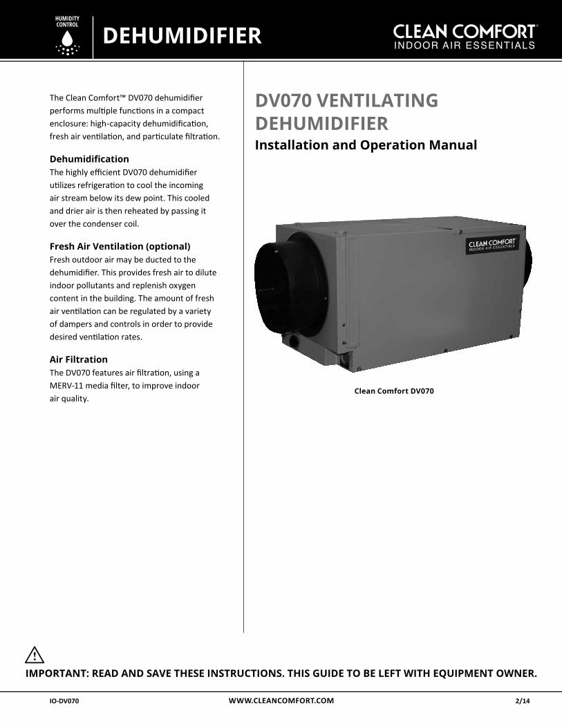
The Clean Comfort™ DV070 dehumidifier performs multiple functions in a compact enclosure: high-capacity dehumidification, fresh air ventilation, and particulate filtration. DehumidificationThe highly efficient DV070 dehumidifier utilizes refrigeration to cool the incoming air stream below its dew point. This cooled and drier air is then reheated by passing it over the condenser coil.
Fresh Air Ventilation (optional)Fresh outdoor air may be ducted to the dehumidifier. This provides fresh air to dilute indoor pollutants and replenish oxygen content in the building. The amount of fresh air ventilation can be regulated by a variety of dampers and controls in order to provide desired ventilation rates.
Air FiltrationThe DV070 features air filtration, using a MERV-11 media filter, to improve indoor air quality.
Clean Comfort DV070
WWW.CLEANCOMFORT.COM2
TABLE OF CONTENTS
IO-DV070 IO-DV070
*INSTALLATION DATE (MM/DD/YYYY) ( / / )
________________________________________________________________ MODEL#: ____________________________________________________ SERIAL#: _____________________________________________________ *Ask Dealer to provide this information.
Our continuing commitment to quality products may mean a change in specifications without notice.
© 2014 DAIKIN NORTH AMERICA LLC Houston, Texas • USAwww.cleancomfort.com
1-855-239-2665
Proprietary Notice This document and the information disclosed herein are proprietary data of Daikin North America LLC. Neither this document nor the information contained herein shall be reproduced, used, or disclosed to others without the written authorization of Daikin North America LLC except to the extent required for installation or maintenance of recipient’s equipment.
Liability Notice Daikin North America LLC does not accept any liability for installations of dehumidification equipment installed by unqualified personnel or the use of parts/components/equipment that are not authorized or approved by Daikin.
Copyright Notice Copyright 2014, Daikin North America LLC All rights reserved.
INTRODUCTION ................................................ 1 SAFETY PRECAUTIONS ..................................... 3INTENDED APPLICATION ................................. 3REGISTRATIONS ................................................ 3OPTIONAL PARTS LIST ..................................... 3SPECIFICATIONS ............................................... 3INSTALLATION ................................................. 3
Installation Considerations ..........................................4
Power Accessibility .................................................... 4
Space ......................................................................... 4
Low Voltage Wiring ................................................... 4
Back-Draft Damper .................................................... 4
Support Structure and Suspension ........................... 4
Electrical Requirements ............................................ 4
Condensate (Water) Removal ................................... 5
Lifting Condensate .................................................... 5
Condensate Pump Installation (Optional) ................. 5
DUCTING ........................................................... 6Installing Duct Collars ....................................................6
Ducting for Dehumidification ........................................6
Fresh Air/Supply Air .......................................................6
Ducting for Fresh Air (Optional) ....................................6
Fresh Air Ventilation ......................................................7
Installation in a Basement or Crawlspace with an Existing Forced-Air HVAC System ...................................7
Installation in an Attic with an Existing Forced-Air HVAC System ...................................7
Installation in a Home withNo Existing Forced-Air HVAC System .............................8
Ducting for High-Efficiency Filtration .............................8
Converting to Vertical Discharge Airflow .......................8
Quiet Installation ...........................................................9
CONTROLS ......................................................... 9Wiring of Digital Control ..............................................10
Digital Humidifier and Ventilation Control ..................11
MAINTENANCE ............................................... 12High-Efficiency Air Filter ..............................................12
Impeller Fan Oiling .......................................................12
Optional Fresh Air Intake ............................................12
WIRING SCHEMATIC ........................................ 13SERVICE PARTS LIST ....................................... 14SERVICE ........................................................... 14Technical Description ofDehumidifier Operation ..............................................14
TROUBLESHOOTING ...................................... 15Refrigerant Charging ...................................................16
OPERATION ..................................................... 16Remote Controls ..........................................................16
Humidity Control .........................................................16
Programmable Ventilation Timer ................................16
Motorized Ventilation Damper ....................................17
CONDENSATE PUMP INSTALLATION............. 18WARRANTY ..................................................... 20
WWW.CLEANCOMFORT.COM 3
SPECIFICATIONS
IO-DV070 IO-DV070
Safety Precautions Read the installation, operation and maintenance instruc-tions carefully before installing and operating this device. Proper adherence to these instructions is essential to obtain maximum benefit from your DV070 Ventilating Dehumidifier.
READ AND SAVE THESE INSTRUCTIONS
i WARNING!
This symbol indicates important instructions. Failure to heed them can result in serious injury or death.
i CAUTION!
This symbol indicates important instructions. Failure to heed them can result in injury or material property damage.
Intended Application for DV070 Dehumidifier For the ideal installation, draw air from the central part of the home and return it to isolated areas of the home like the bedrooms, den, utility room, or family room. The ductwork of the existing heating system can be used to supply air to the home.
Registrations The Clean Comfort DV070 conforms to UL STD 474 and CSA Standard C22.2 No.92.
Specifications Part Number: DV070Blower: 150 CFM @ 0.0" WG 130 CFM @ 0.4" WG
Power: 580 Watts @ 80°F and 60% RH
Supply Voltage: 110-120 VAC – 1phase – 60 Hz
Current Draw: 5.1 Amps
Energy Factor: 2.4 L/kWh
Operating Temp.: 49 °F (9 °C) Min, 95°F (35 °C) Max
Sized For: Up to 1800 Sq. Ft. - Typical
Performance at 80° F/60% RH: Capacity: 70 Pints/Day (33 L/Day) Efficiency: 5.0 pints/kWhr (2.4 L/kWhr)
Duct Connections: 8" Round inlet; 8" Round outlet
Air Filter: Efficiency: MERV-11 Standard 65% Efficient ASHRAE Dust Spot Test Size: 9" x 11" x1"
Power Cord: 9 ft (2.7 m) Drain Connection: 3/4" Threaded FNPTRefrigerant Type: R410a (Refer to manufacturer's label for more information)
INSTALLATIONInstallation Considerations
i CAUTION!
Prior to installation of the DV070, the following consider- ations for selecting the location for this equipment should be reviewed. The DV070 can be installed in a variety of locations to meet the owner's needs, and integrate with existing forced-air systems or existing ductwork if desired. The location choice is contingent on a variety of requirements not limited to: ease of service, controls access, drainage, filtration, access to power, fresh-air ventilation, water damage prevention and current regulatory codes (ASHRAE, fire, etc). Please address all of these issues before you select the device's location.
Dimensions: Unit ShippingWidth: 12" (30.5 cm) 15 ⅝" (40 cm)Height: 12" (30.5 cm) 16" (40 cm)Depth: 28" (71 cm) 31 ⅝" (80 cm)
Weight: 55 lbs (25 kg) 65 lbs (30 kg)
Optional Parts List for DV070 Ventilating Dehumidifier Part No. Description DVP-4034748 Digital ControlDVP-4034753 Digital Control with remoteDVP-4034731 9"x11"x1" MERV 11 filter for DV070 dehumidifierDVP-4034737 6" Duct Damper, Motorized for DV070, DV090 and DV155 dehumidifiersDVP-4034739 8" Backdraft Gravity Damper for DV070 dehumidifierDVP-4034746 Hang Kit for DV070
WWW.CLEANCOMFORT.COM4
INSTALLATION CONSIDERATIONS
IO-DV070 IO-DV070
Installation Considerations• This equipment is designed to be installed INDOORS
IN A SPACE THAT IS PROTECTED FROM RAIN AND FLOODING.
• Install the unit with enough space to access one of the side panels for maintenance and service.
• Avoid directing the discharge air at people, or over the water in pool areas.
• If used near a pool or spa; be certain there is NO chance the unit could fall into the water, splashed and that it is plugged into a GFCI (GROUND FAULT CIRCUIT INTERRUPT) OUTLET.
• DO NOT use the unit as a bench or table.
• DO NOT place the unit directly on structural members.
• A drain pan MUST be placed under the unit if installed above a living area or above an area where water leak-age could cause damage.
• Locate the unit near the existing HVAC system to mini-mize the required ductwork for connecting it to the existing air handling system. The controls for the dehu-midifier are remote from the unit and must be located in the space that is to be conditioned. The controls are low voltage (24 VAC) and should be connected to the unit with low voltage thermostat cable.
• If fresh air ventilation is desired, thought should be given to the location for the fresh air ducting. A 6" round insulated duct will have to be attached to the 8" supply duct of the unit and run to the outside of the home to bring in fresh air. Use an 8" insulated round duct for lengths of more than 50 feet or if more than 100 CFM is needed. Consult local codes for necessary distances from exhaust ports when installing fresh air return.
Power Accessibility Unit should be located in an area where the cord's length (9') can easily reach a 115VAC electrical outlet with a minimum of a 15 A circuit capacity.
Space Location should have enough clearance to handle the unit's overall dimensions as well as the necessary return/supply ductwork to the unit. Allow a minimum 12" clearance to the side of the unit to allow for filter removal and replacement.
Low Voltage Wiring Unit location should be in an area where field wiring the remote controls (low voltage) to the unit will be possible.
Back-Draft DamperIt is recommended that a backdraft damper be used in the supply duct of the DV070, especially when connecting to the supply ducting system. The backdraft damper prevents supply air from counter flowing through the DV070 when it is not operating. The unit location should be chosen to allow installation of this accessory if requested by the end user.
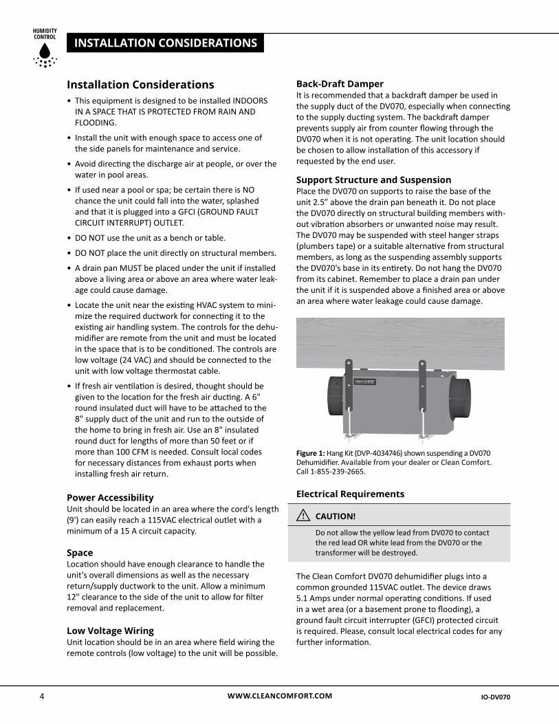
Support Structure and Suspension Place the DV070 on supports to raise the base of the unit 2.5” above the drain pan beneath it. Do not place the DV070 directly on structural building members with-out vibration absorbers or unwanted noise may result. The DV070 may be suspended with steel hanger straps (plumbers tape) or a suitable alternative from structural members, as long as the suspending assembly supports the DV070's base in its entirety. Do not hang the DV070 from its cabinet. Remember to place a drain pan under the unit if it is suspended above a finished area or above an area where water leakage could cause damage.
Electrical Requirements
i CAUTION!
Do not allow the yellow lead from DV070 to contact the red lead OR white lead from the DV070 or the transformer will be destroyed.
The Clean Comfort DV070 dehumidifier plugs into a common grounded 115VAC outlet. The device draws 5.1 Amps under normal operating conditions. If used in a wet area (or a basement prone to flooding), a ground fault circuit interrupter (GFCI) protected circuit is required. Please, consult local electrical codes for any further information.
Figure 1: Hang Kit (DVP-4034746) shown suspending a DV070 Dehumidifier. Available from your dealer or Clean Comfort. Call 1-855-239-2665.
WWW.CLEANCOMFORT.COM 5
CONDENSATE REMOVAL
IO-DV070 IO-DV070
The DV070 can be controlled by a variety of devices including the Clean Comfort DVP-4034748 or DVP-4034753 digital controls. The controls are to be located remotely from the unit and located in the space to be conditioned. The controls are low voltage (24 VAC) and should be connected to the DV070 with low voltage wire (thermostat or other appropriate).
Install the digital control in a central area of the home where it will sense the relative humidity accurately.
i CAUTION!
Do not install the control where it may not accurately sense the relative humidity such as near HVAC supply registers, exterior doors, windows, water sources, or on an outside wall.
The installer must supply the wiring between the DV070 and the control. Be sure to safely route the control wiring to prevent damage during installation.
i CAUTION!
Do not cross wires when connecting the DV070 and the control or damage to the transformer may result. The remote controls of the DV070 are powered by a low voltage circuit (24VAC) and must NEVER contact or be connected to a high voltage circuit. The control wires leaving the DV070 and the control are numbered and color-coded to prevent confusion. Some of the control wires leaving the DV070 may not be used with certain control and should be left unconnected with wire nuts taped onto the stripped ends for safety. Be sure to consult the electrical schematic in this manual or inside the access panel of the DV070 before making control connections.
Condensate (Water) Removal The Clean Comfort DV070 dehumidifier generates condensate. Condensate drains by gravity via the drain port. Install a 3/4" male NPT adapter to the drain pan. It is necessary to assemble your own drain pipe assembly utilizing 3/4" PVC pipe to route the condensate to a drain. Pitch/grade of drain should be 1" per 10'.
Take care when installing drain pipe to drain port of the DV070; Use an adjustable wrench to secure the drain port.
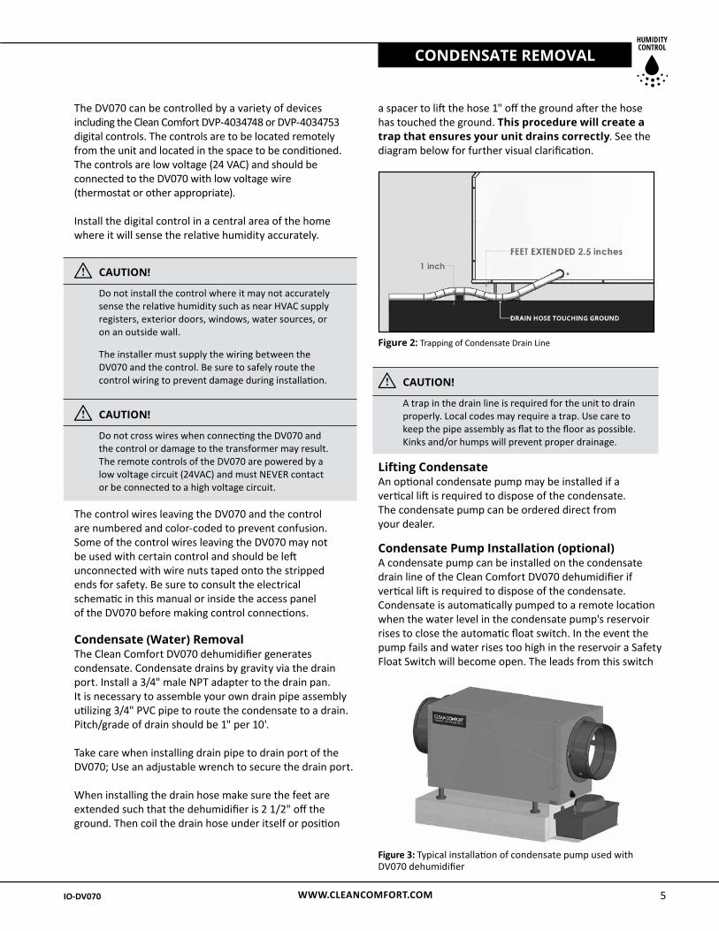
When installing the drain hose make sure the feet are extended such that the dehumidifier is 2 1/2" off the ground. Then coil the drain hose under itself or position
a spacer to lift the hose 1" off the ground after the hose has touched the ground. This procedure will create a trap that ensures your unit drains correctly. See the diagram below for further visual clarification.
i CAUTION!
A trap in the drain line is required for the unit to drain properly. Local codes may require a trap. Use care to keep the pipe assembly as flat to the floor as possible. Kinks and/or humps will prevent proper drainage.
Lifting Condensate An optional condensate pump may be installed if a vertical lift is required to dispose of the condensate. The condensate pump can be ordered direct from your dealer.
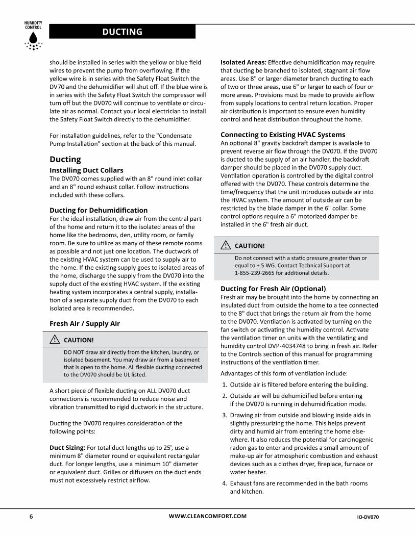
Condensate Pump Installation (optional)A condensate pump can be installed on the condensate drain line of the Clean Comfort DV070 dehumidifier if vertical lift is required to dispose of the condensate. Condensate is automatically pumped to a remote location when the water level in the condensate pump's reservoir rises to close the automatic float switch. In the event the pump fails and water rises too high in the reservoir a Safety Float Switch will become open. The leads from this switch
Figure 3: Typical installation of condensate pump used with DV070 dehumidifier
Figure 2: Trapping of Condensate Drain Line
WWW.CLEANCOMFORT.COM6
DUCTING
IO-DV070 IO-DV070
should be installed in series with the yellow or blue field wires to prevent the pump from overflowing. If the yellow wire is in series with the Safety Float Switch the DV70 and the dehumidifier will shut off. If the blue wire is in series with the Safety Float Switch the compressor will turn off but the DV070 will continue to ventilate or circu-late air as normal. Contact your local electrician to install the Safety Float Switch directly to the dehumidifier.
For installation guidelines, refer to the "Condensate Pump Installation" section at the back of this manual.
Ducting Installing Duct CollarsThe DV070 comes supplied with an 8" round inlet collar and an 8" round exhaust collar. Follow instructions included with these collars.
Ducting for DehumidificationFor the ideal installation, draw air from the central part of the home and return it to the isolated areas of the home like the bedrooms, den, utility room, or family room. Be sure to utilize as many of these remote rooms as possible and not just one location. The ductwork of the existing HVAC system can be used to supply air to the home. If the existing supply goes to isolated areas of the home, discharge the supply from the DV070 into the supply duct of the existing HVAC system. If the existing heating system incorporates a central supply, installa-tion of a separate supply duct from the DV070 to each isolated area is recommended.
Fresh Air / Supply Air
i CAUTION!
DO NOT draw air directly from the kitchen, laundry, or isolated basement. You may draw air from a basement that is open to the home. All flexible ducting connected to the DV070 should be UL listed.
A short piece of flexible ducting on ALL DV070 duct connections is recommended to reduce noise and vibration transmitted to rigid ductwork in the structure.
Ducting the DV070 requires consideration of the following points:
Duct Sizing: For total duct lengths up to 25', use a minimum 8" diameter round or equivalent rectangular duct. For longer lengths, use a minimum 10" diameter or equivalent duct. Grilles or diffusers on the duct ends must not excessively restrict airflow.
Isolated Areas: Effective dehumidification may require that ducting be branched to isolated, stagnant air flow areas. Use 8" or larger diameter branch ducting to each of two or three areas, use 6" or larger to each of four or more areas. Provisions must be made to provide airflow from supply locations to central return location. Proper air distribution is important to ensure even humidity control and heat distribution throughout the home.
Connecting to Existing HVAC SystemsAn optional 8" gravity backdraft damper is available to prevent reverse air flow through the DV070. If the DV070 is ducted to the supply of an air handler, the backdraft damper should be placed in the DV070 supply duct. Ventilation operation is controlled by the digital control offered with the DV070. These controls determine the time/frequency that the unit introduces outside air into the HVAC system. The amount of outside air can be restricted by the blade damper in the 6" collar. Some control options require a 6" motorized damper be installed in the 6" fresh air duct.
i CAUTION!
Do not connect with a static pressure greater than or equal to +.5 WG. Contact Technical Support at 1-855-239-2665 for additional details.
Ducting for Fresh Air (Optional) Fresh air may be brought into the home by connecting an insulated duct from outside the home to a tee connected to the 8" duct that brings the return air from the home to the DV070. Ventilation is activated by turning on the fan switch or activating the humidity control. Activate the ventilation timer on units with the ventilating and humidity control DVP-4034748 to bring in fresh air. Refer to the Controls section of this manual for programming instructions of the ventilation timer.
Advantages of this form of ventilation include:
1. Outside air is filtered before entering the building.
2. Outside air will be dehumidified before entering if the DV070 is running in dehumidification mode.
3. Drawing air from outside and blowing inside aids in slightly pressurizing the home. This helps prevent dirty and humid air from entering the home else-where. It also reduces the potential for carcinogenic radon gas to enter and provides a small amount of make-up air for atmospheric combustion and exhaust devices such as a clothes dryer, fireplace, furnace or water heater.
4. Exhaust fans are recommended in the bath rooms and kitchen.
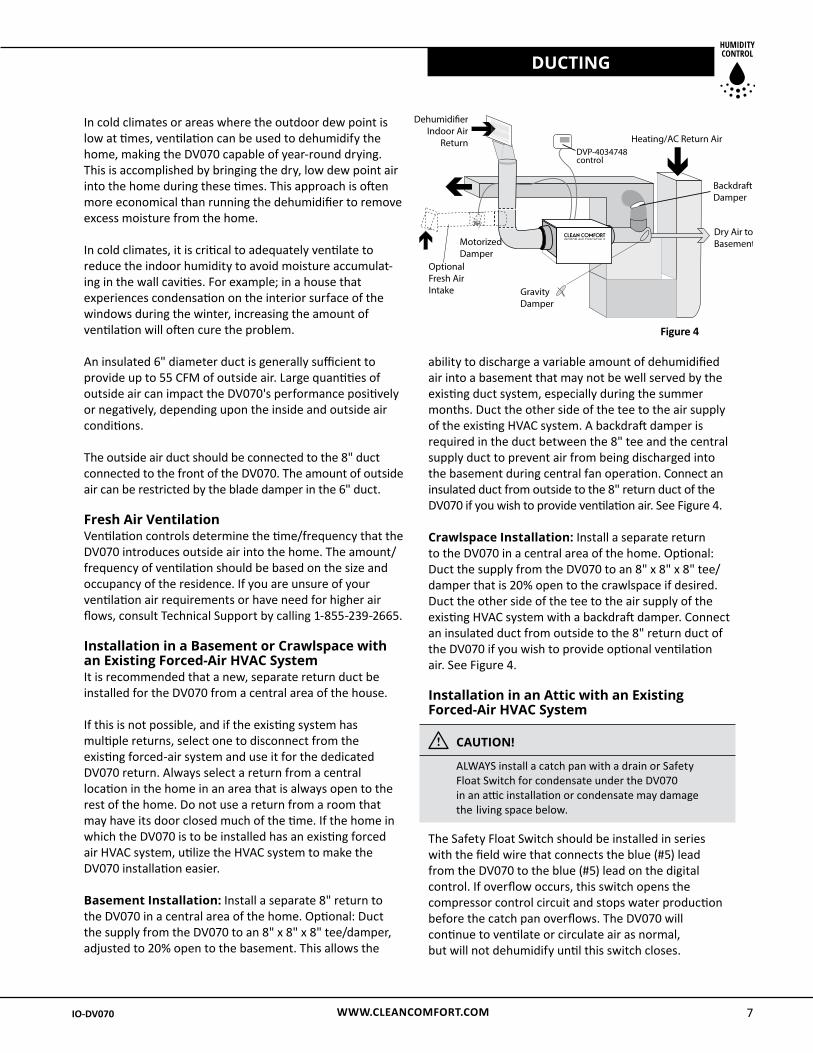
Dehumidi�erIndoor Air
ReturnDVP-4034748control
Heating/AC Return Air
BackdraftDamper
Dry Air toBasement
GravityDamper
MotorizedDamper
OptionalFresh AirIntake
WWW.CLEANCOMFORT.COM 7
DUCTING
IO-DV070 IO-DV070
In cold climates or areas where the outdoor dew point is low at times, ventilation can be used to dehumidify the home, making the DV070 capable of year-round drying. This is accomplished by bringing the dry, low dew point air into the home during these times. This approach is often more economical than running the dehumidifier to remove excess moisture from the home.
In cold climates, it is critical to adequately ventilate to reduce the indoor humidity to avoid moisture accumulat-ing in the wall cavities. For example; in a house that experiences condensation on the interior surface of the windows during the winter, increasing the amount of ventilation will often cure the problem.
An insulated 6" diameter duct is generally sufficient to provide up to 55 CFM of outside air. Large quantities of outside air can impact the DV070's performance positively or negatively, depending upon the inside and outside air conditions.
The outside air duct should be connected to the 8" duct connected to the front of the DV070. The amount of outside air can be restricted by the blade damper in the 6" duct.
Fresh Air VentilationVentilation controls determine the time/frequency that the DV070 introduces outside air into the home. The amount/frequency of ventilation should be based on the size and occupancy of the residence. If you are unsure of your ventilation air requirements or have need for higher air flows, consult Technical Support by calling 1-855-239-2665.
Installation in a Basement or Crawlspace with an Existing Forced-Air HVAC System It is recommended that a new, separate return duct be installed for the DV070 from a central area of the house.
If this is not possible, and if the existing system has multiple returns, select one to disconnect from the existing forced-air system and use it for the dedicated DV070 return. Always select a return from a central location in the home in an area that is always open to the rest of the home. Do not use a return from a room that may have its door closed much of the time. If the home in which the DV070 is to be installed has an existing forced air HVAC system, utilize the HVAC system to make the DV070 installation easier.
Basement Installation: Install a separate 8" return to the DV070 in a central area of the home. Optional: Duct the supply from the DV070 to an 8" x 8" x 8" tee/damper, adjusted to 20% open to the basement. This allows the
ability to discharge a variable amount of dehumidified air into a basement that may not be well served by the existing duct system, especially during the summer months. Duct the other side of the tee to the air supply of the existing HVAC system. A backdraft damper is required in the duct between the 8" tee and the central supply duct to prevent air from being discharged into the basement during central fan operation. Connect an insulated duct from outside to the 8" return duct of the DV070 if you wish to provide ventilation air. See Figure 4.
Crawlspace Installation: Install a separate return to the DV070 in a central area of the home. Optional: Duct the supply from the DV070 to an 8" x 8" x 8" tee/damper that is 20% open to the crawlspace if desired. Duct the other side of the tee to the air supply of the existing HVAC system with a backdraft damper. Connect an insulated duct from outside to the 8" return duct of the DV070 if you wish to provide optional ventilation air. See Figure 4.
Installation in an Attic with an Existing Forced-Air HVAC System
i CAUTION!
ALWAYS install a catch pan with a drain or Safety Float Switch for condensate under the DV070 in an attic installation or condensate may damage the living space below.
The Safety Float Switch should be installed in series with the field wire that connects the blue (#5) lead from the DV070 to the blue (#5) lead on the digital control. If overflow occurs, this switch opens the compressor control circuit and stops water production before the catch pan overflows. The DV070 will continue to ventilate or circulate air as normal, but will not dehumidify until this switch closes.
Figure 4
IO-DV070 IO-DV070WWW.CLEANCOMFORT.COM8
DUCTING
IO-DV070 IO-DV070
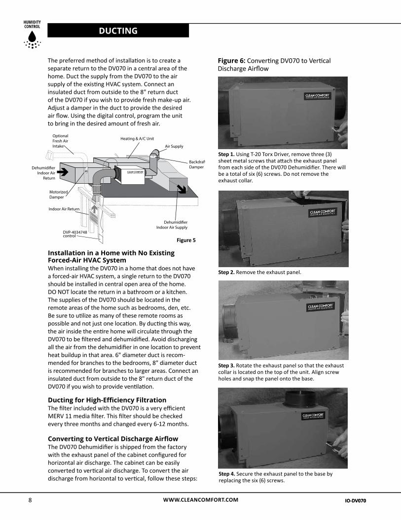
Step 4. Secure the exhaust panel to the base by replacing the six (6) screws.
The preferred method of installation is to create a separate return to the DV070 in a central area of the home. Duct the supply from the DV070 to the air supply of the existing HVAC system. Connect an insulated duct from outside to the 8" return duct of the DV070 if you wish to provide fresh make-up air. Adjust a damper in the duct to provide the desired air flow. Using the digital control, program the unit to bring in the desired amount of fresh air.
Step 1. Using T-20 Torx Driver, remove three (3) sheet metal screws that attach the exhaust panel from each side of the DV070 Dehumidifier. There will be a total of six (6) screws. Do not remove the exhaust collar.
Step 2. Remove the exhaust panel.
Step 3. Rotate the exhaust panel so that the exhaust collar is located on the top of the unit. Align screw holes and snap the panel onto the base.
Indoor Air Return
Air Supply
Heating & A/C Unit
Dehumidi�erIndoor Air
Return
Dehumidi�erIndoor Air Supply
BackdraftDamper
MotorizedDamper
OptionalFresh AirIntake
DVP-4034748control
Figure 5
Installation in a Home with No Existing Forced-Air HVAC SystemWhen installing the DV070 in a home that does not have a forced-air HVAC system, a single return to the DV070 should be installed in central open area of the home. DO NOT locate the return in a bathroom or a kitchen. The supplies of the DV070 should be located in the remote areas of the home such as bedrooms, den, etc. Be sure to utilize as many of these remote rooms as possible and not just one location. By ducting this way, the air inside the entire home will circulate through the DV070 to be filtered and dehumidified. Avoid discharging all the air from the dehumidifier in one location to prevent heat buildup in that area. 6" diameter duct is recom-mended for branches to the bedrooms, 8" diameter duct is recommended for branches to larger areas. Connect an insulated duct from outside to the 8" return duct of the DV070 if you wish to provide ventilation.
Ducting for High-Efficiency Filtration The filter included with the DV070 is a very efficient MERV 11 media filter. This filter should be checked every three months and changed every 6-12 months.
Converting to Vertical Discharge AirflowThe DV070 Dehumidifier is shipped from the factory with the exhaust panel of the cabinet configured for horizontal air discharge. The cabinet can be easily converted to vertical air discharge. To convert the air discharge from horizontal to vertical, follow these steps:
Figure 6: Converting DV070 to Vertical Discharge Airflow
WWW.CLEANCOMFORT.COM 9
CONTROLS
IO-DV070 IO-DV070IO-DV070 IO-DV070
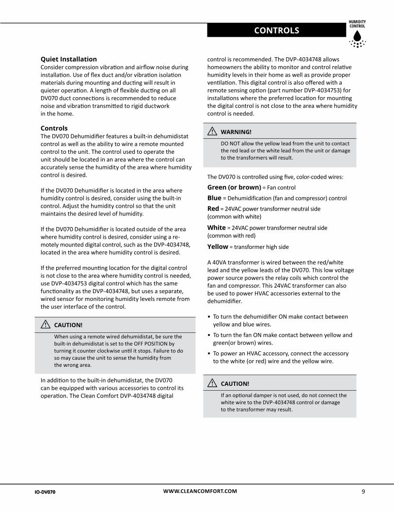
Quiet Installation Consider compression vibration and airflow noise during installation. Use of flex duct and/or vibration isolation materials during mounting and ducting will result in quieter operation. A length of flexible ducting on all DV070 duct connections is recommended to reduce noise and vibration transmitted to rigid ductwork in the home. Controls The DV070 Dehumidifier features a built-in dehumidistat control as well as the ability to wire a remote mounted control to the unit. The control used to operate the unit should be located in an area where the control can accurately sense the humidity of the area where humidity control is desired.
If the DV070 Dehumidifier is located in the area where humidity control is desired, consider using the built-in control. Adjust the humidity control so that the unit maintains the desired level of humidity.
If the DV070 Dehumidifier is located outside of the area where humidity control is desired, consider using a re-motely mounted digital control, such as the DVP-4034748, located in the area where humidity control is desired.
If the preferred mounting location for the digital control is not close to the area where humidity control is needed, use DVP-4034753 digital control which has the same functionality as the DVP-4034748, but uses a separate, wired sensor for monitoring humidity levels remote from the user interface of the control.
i CAUTION!
When using a remote wired dehumidistat, be sure the built-in dehumidistat is set to the OFF POSITION by turning it counter clockwise until it stops. Failure to do so may cause the unit to sense the humidity from the wrong area.
In addition to the built-in dehumidistat, the DV070 can be equipped with various accessories to control its operation. The Clean Comfort DVP-4034748 digital
control is recommended. The DVP-4034748 allows homeowners the ability to monitor and control relative humidity levels in their home as well as provide proper ventilation. This digital control is also offered with a remote sensing option (part number DVP-4034753) for installations where the preferred location for mounting the digital control is not close to the area where humidity control is needed.
i WARNING!
DO NOT allow the yellow lead from the unit to contact the red lead or the white lead from the unit or damage to the transformers will result.
The DV070 is controlled using five, color-coded wires:
Green (or brown) = Fan control
Blue = Dehumidification (fan and compressor) control
Red = 24VAC power transformer neutral side (common with white)
White = 24VAC power transformer neutral side (common with red)
Yellow = transformer high side
A 40VA transformer is wired between the red/white lead and the yellow leads of the DV070. This low voltage power source powers the relay coils which control the fan and compressor. This 24VAC transformer can also be used to power HVAC accessories external to the dehumidifier.
• To turn the dehumidifier ON make contact between yellow and blue wires.
• To turn the fan ON make contact between yellow and green(or brown) wires.
• To power an HVAC accessory, connect the accessory to the white (or red) wire and the yellow wire.
i CAUTION!
If an optional damper is not used, do not connect the white wire to the DVP-4034748 control or damage to the transformer may result.
WWW.CLEANCOMFORT.COM10
CONTROLS
IO-DV070 IO-DV070
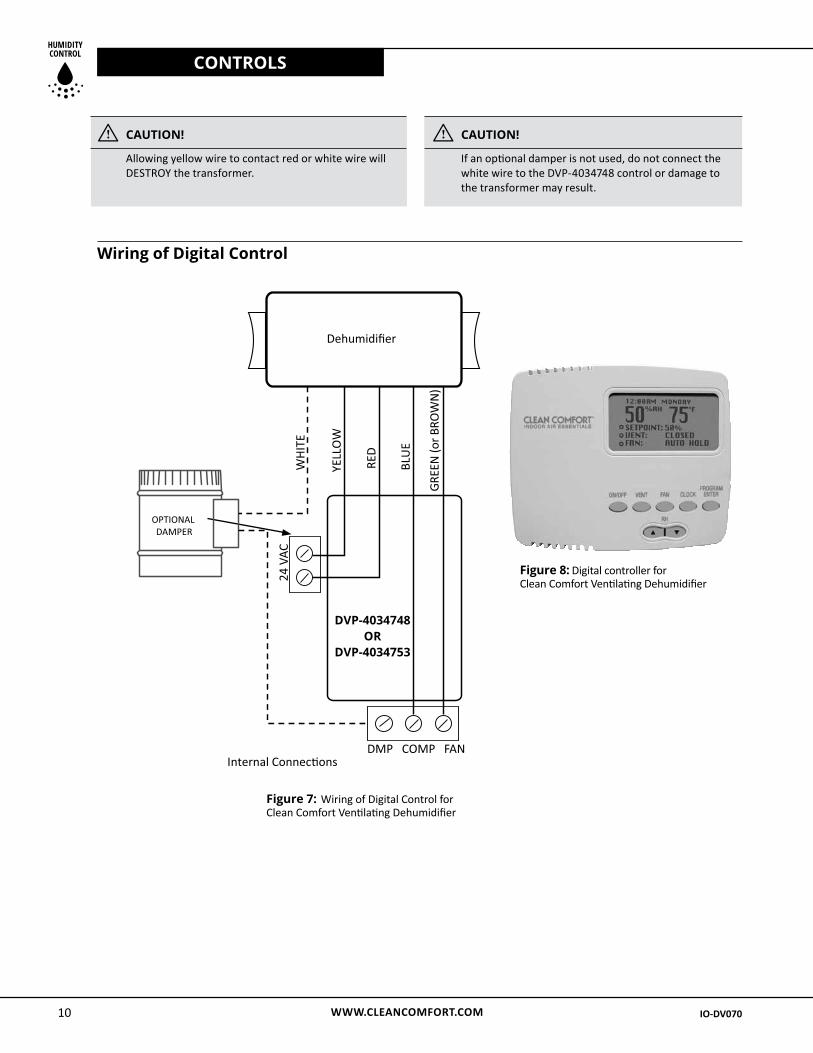
Figure 8: Digital controller for Clean Comfort Ventilating Dehumidifier
Dehumidifier
RED
Digital control for Clean Comfort Ventilating Dehumidifier
YELL
OW
BLU
E
GREE
N (o
r BRO
WN)
WHI
TE
Internal Connec�ons
OPTIONAL DAMPER
24 V
AC
DMP COMP FAN
Figure 7: Wiring of Digital Control for Clean Comfort Ventilating Dehumidifier
DVP-4034748OR
DVP-4034753
i CAUTION!
Allowing yellow wire to contact red or white wire will DESTROY the transformer.
i CAUTION!
If an optional damper is not used, do not connect the white wire to the DVP-4034748 control or damage to the transformer may result.
Wiring of Digital Control
WWW.CLEANCOMFORT.COM 11
CONTROLS
IO-DV070 IO-DV070
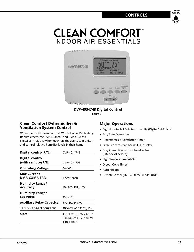
Clean Comfort Dehumidifier & Ventilation System ControlWhen used with Clean Comfort Whole House Ventilating Dehumidifiers, the DVP-4034748 and DVP-4034753 digital controls allow homeowners the ability to monitor and control relative humidity levels in their home.
Digital control P/N: DVP-4034748
Digital control (with remote) P/N: DVP-4034753
Operating Voltage: 24VAC
Max Current DMP, COMP, FAN: 1 AMP each
Humidity Range/ Accuracy: 10 - 95% RH, ± 5%
Humidity Range/ Set Point: 35 - 70%
Auxillary Relay Capacity: 5 Amps, 24VAC
Temp Range/Accuracy: 30°-90°F (-1°-32°C), 2%
Size: 4.95"L x 1.06"W x 4.19" H (12.6 cm L x 2.7 cm W x 10.6 cm H)
Major Operations • Digital control of Relative Humidity (Digital Set-Point)
• Fan/Filter Operation
• Programmable Ventilation Timer
• Large, easy-to-read backlit LCD display
• Easy interaction with air handler fan (Interlock/Lockout)
• High Temperature Cut-Out
• Dryout Cycle Timer
• Auto Reboot
• Remote Sensor (DVP-4034753 model ONLY)
DVP-4034748 Digital ControlFigure 9
WWW.CLEANCOMFORT.COM12
MAINTENANCE
IO-DV070 IO-DV070
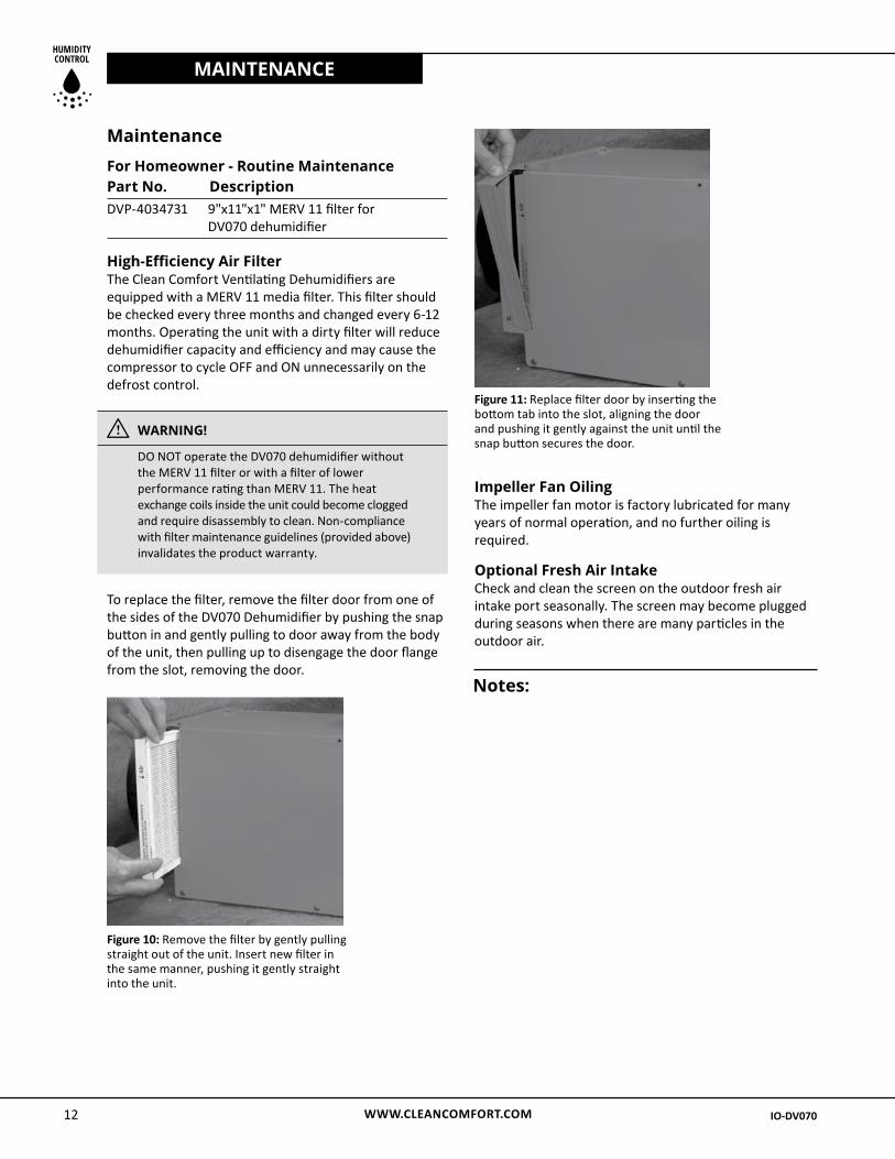
Maintenance For Homeowner - Routine Maintenance Part No. Description DVP-4034731 9"x11"x1" MERV 11 filter for DV070 dehumidifier
High-Efficiency Air Filter The Clean Comfort Ventilating Dehumidifiers are equipped with a MERV 11 media filter. This filter should be checked every three months and changed every 6-12 months. Operating the unit with a dirty filter will reduce dehumidifier capacity and efficiency and may cause the compressor to cycle OFF and ON unnecessarily on the defrost control.
Figure 10: Remove the filter by gently pulling straight out of the unit. Insert new filter in the same manner, pushing it gently straight into the unit.
Figure 11: Replace filter door by inserting the bottom tab into the slot, aligning the door and pushing it gently against the unit until the snap button secures the door.
Notes:
Impeller Fan Oiling The impeller fan motor is factory lubricated for many years of normal operation, and no further oiling is required.
Optional Fresh Air Intake Check and clean the screen on the outdoor fresh air intake port seasonally. The screen may become plugged during seasons when there are many particles in the outdoor air.
i WARNING!
DO NOT operate the DV070 dehumidifier without the MERV 11 filter or with a filter of lower performance rating than MERV 11. The heat exchange coils inside the unit could become clogged and require disassembly to clean. Non-compliance with filter maintenance guidelines (provided above) invalidates the product warranty.
To replace the filter, remove the filter door from one of the sides of the DV070 Dehumidifier by pushing the snap button in and gently pulling to door away from the body of the unit, then pulling up to disengage the door flange from the slot, removing the door.
WWW.CLEANCOMFORT.COM 13IO-DV070 IO-DV070
WIRING SCHEMATIC
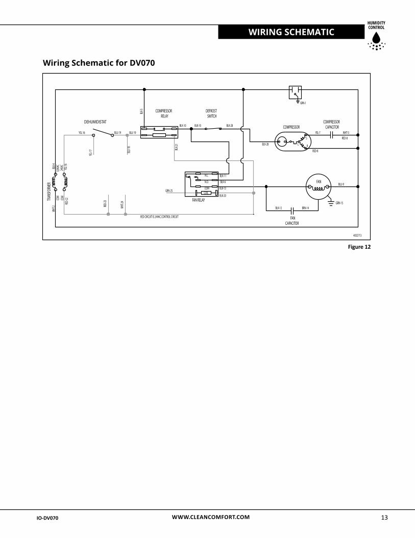
Wiring Schematic for DV070
Figure 12
WWW.CLEANCOMFORT.COM14
SERVICE
IO-DV070 IO-DV070
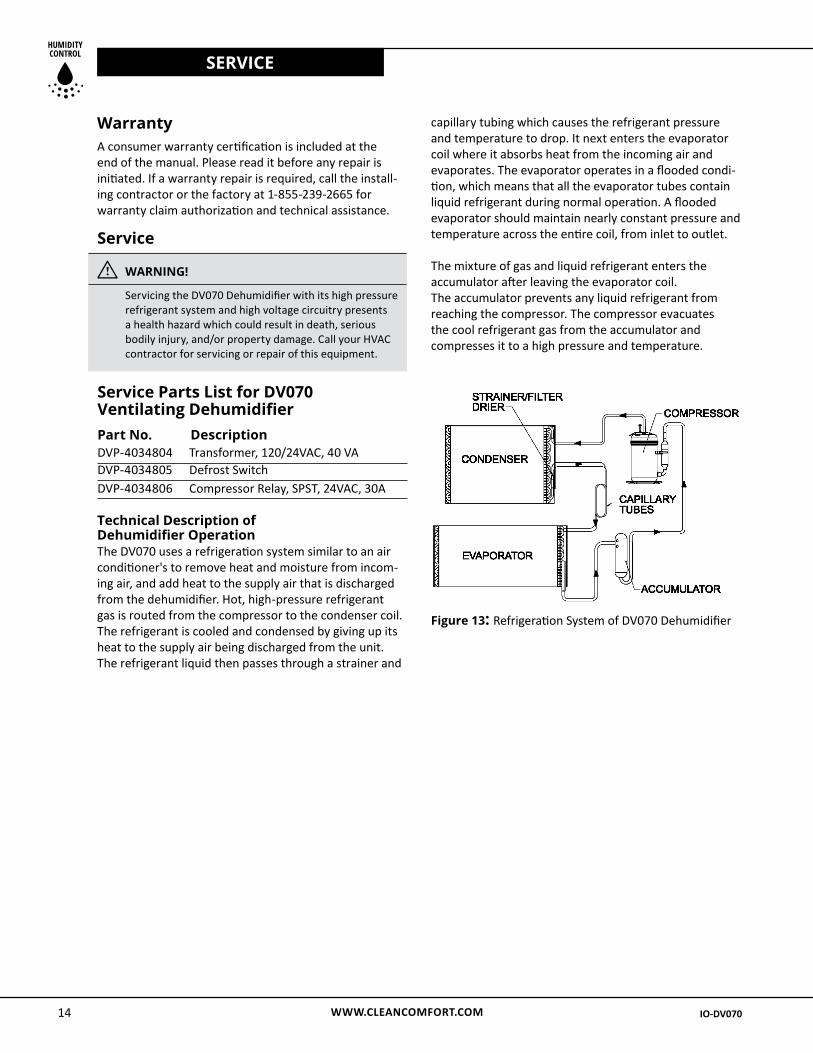
Figure 13: Refrigeration System of DV070 Dehumidifier
Service Parts List for DV070 Ventilating DehumidifierPart No. Description DVP-4034804 Transformer, 120/24VAC, 40 VA DVP-4034805 Defrost Switch DVP-4034806 Compressor Relay, SPST, 24VAC, 30A
Service
i WARNING! Servicing the DV070 Dehumidifier with its high pressure refrigerant system and high voltage circuitry presents a health hazard which could result in death, serious bodily injury, and/or property damage. Call your HVAC contractor for servicing or repair of this equipment.
Technical Description of Dehumidifier Operation The DV070 uses a refrigeration system similar to an air conditioner's to remove heat and moisture from incom-ing air, and add heat to the supply air that is discharged from the dehumidifier. Hot, high-pressure refrigerant gas is routed from the compressor to the condenser coil. The refrigerant is cooled and condensed by giving up its heat to the supply air being discharged from the unit. The refrigerant liquid then passes through a strainer and
Warranty A consumer warranty certification is included at the end of the manual. Please read it before any repair is initiated. If a warranty repair is required, call the install-ing contractor or the factory at 1-855-239-2665 for warranty claim authorization and technical assistance.
capillary tubing which causes the refrigerant pressure and temperature to drop. It next enters the evaporator coil where it absorbs heat from the incoming air and evaporates. The evaporator operates in a flooded condi-tion, which means that all the evaporator tubes contain liquid refrigerant during normal operation. A flooded evaporator should maintain nearly constant pressure and temperature across the entire coil, from inlet to outlet.
The mixture of gas and liquid refrigerant enters the accumulator after leaving the evaporator coil. The accumulator prevents any liquid refrigerant from reaching the compressor. The compressor evacuates the cool refrigerant gas from the accumulator and compresses it to a high pressure and temperature.
WWW.CLEANCOMFORT.COM 15IO-DV070 IO-DV070
TROUBLESHOOTING
Neither fan nor compressor running. Dehumidification is being called for. No fan call.
1. Unit unplugged or no power to outlet.
2. Humidity control set too high.
3. Loose connection in internal or control wiring.
4. Defective Compressor relay.
5. Defective control transformer.
Compressor is not running. Dehumidification is being called for. No fan call.
1. Defective compressor run capacitor.
2. Loose connection in compressor circuit.
3. Defective compressor overload.
4. Defective compressor.
5. Defrost thermostat open.
6. Defective compressor relay.
Compressor cycles on and off. Dehumidification is being called for. No fan call.
1. Low ambient temperature and/or humidity causing unit to cycle through defrost mode.
2. Defective compressor overload.
3. Defective compressor.
4. Defrost thermostat defective.
5. Dirty air filter(s) or air flow restricted.
6. Defective fan relay.
Fan is not running. Dehumidification or fan is being called for.
1. Loose connection in fan circuit.
2. Obstruction prevents fan impeller rotation.
3. Defective fan.
4. Defective fan relay.
Low dehumidification capacity (evaporator is frosted continuously). Dehumidification is being called for.
1. Defrost thermostat loose or defective.
2. Low refrigerant charge.
3. Dirty air filter(s) or air flow restricted.
4. Excessively restrictive ducting connected to unit.
No ventilation. Ventilation is being called for.
1. Loose connection in ventilation control circuit.
2. Loose connection in damper power circuit.
3. Defective fresh air damper.
Unit removes some water, but not as much as expected.
1. Air temperature and/or humidity have dropped.
2. Humidity meter and or thermometer used are out of calibration.
3. Unit has entered defrost cycle.
4. Air filter dirty.
5. Defective defrost thermostat.
6. Low refrigerant charge.
7. Air leak such as loose cover or ducting leaks.
8. Defective compressor.
9. Restrictive ducting.
10. Optional Condensate Pump Safety Float Switch open.
Troubleshooting Unit doesn't respond to humidity setpoint on remote wired dehumidistat.
1. Verify built-in dehumidistat is turned to the “OFF” position.
2. Check calibration of the control to determine if it is reading humidity level properly.
3. Verify control wiring is intact by connecting control directly to the pigtail of the unit.
WWW.CLEANCOMFORT.COM16
OPERATION
IO-DV070 IO-DV070
i WARNING!
ELECTRICAL SHOCK HAZARD: Electrical power must be present to perform some tests. These tests should be performed by a qualified service person.
Remote ControlsThe DV070 dehumidifier is controlled by digital controls that are remote from the unit. You may or may not have the devices listed below depending on the model of the control you purchased. If the dehumidifier fails to oper-ate as desired, always check the settings of the controls to insure that they are correct. Check that the controls are receiving 24VAC from the dehumidifier. Check the connections between the dehumidifier, the control, and the field control wiring.
Humidity ControlThe humidity control is an adjustable switch that closes when the relative humidity of the air in which it is located rises to the screen set point. The Clean Comfort DV Series dehumidifier is equipped with an automatic defrost mechanism. If the dehumidifier operates in conditions that develop frost on the evaporator, it will sense the frost build-up and automatically defrost the evaporator. The dehumidifier may not appear to be operating correctly during the defrost sequence, but once the defrost sequence is completed, the unit will resume dehumidifying.
Programmable Ventilation Timer – DVP-4034748 / DVP-4034753The ventilation timer controls the impeller fan and the motorized fresh air damper. When the ventilation timer is activated, the dehumidifier will circulate the indoor air, and bring in fresh air from outside. The ventilation timer should be set for the required ventilation of the residence. The home should be ventilated with fresh air as suggested by applicable codes and standards. If the dehumidifier fails to ventilate as expected, check that the time on the timer is correct. Also check the programs on the timer to be sure that the timer is calling for ventila-tion at the correct times.
i WARNING!
ELECTRICAL SHOCK HAZARD: Electrical power must be present to perform some tests. These tests should be performed by a qualified service person.
Unit Test to Determine Problem: 1. Detach field control wiring connections from
main unit.
2. Connect the yellow and green pigtails from the main unit together; only the fan should run. Disconnect the wires.
3. Connect the yellow and blue pigtails from the main unit together or turn the built-in dehumidistat all the way clockwise to the "ON" position; the compressor and fan should run.
4. If these tests work, the main unit is working properly. You should check the digital control panel and field control wiring for problems next.
5. Remove the digital control panel from the mounting box and detach it from the field installed control wiring. Connect the blue, yellow, and green wires from the control panel directly to the corresponding colored pigtails on the main unit. Leave the green, white and red wires disconnected!
6. Engage the fan switch on the control; the fan should run. Turn off the fan switch.
7. Engage the dehumidistat of the control; the compressor and fan should run.
8. If these tests work, the problem is most likely in the field control wiring.
NOTE: Refrigeration systems should ONLY be serviced by a qualified service technician. If you need additional information, consult Technical Support at 1-855-239-2665.
Refrigerant Charging If the refrigerant charge is lost due to service or a leak, a new charge must be accurately weighed in. If any of the old charge is left in the system, it must be recovered before weighing in the new charge. Refer to the unit nameplate for the correct charge weight and refrigerant type.
WWW.CLEANCOMFORT.COM 17IO-DV070 IO-DV070
OPERATION
Motorized Ventilation DamperThe motorized ventilation damper is controlled by a field-supplied ventilation timer, such as the Clean Comfort DVP-4034748 control. The damper will open when the ventilation timer is activated to allow fresh air into the home through the 6" diameter fresh air inlet return duct. The motorized ventilation damper will remain closed when the ventilation timer is not activated to prevent over-ventilating the home when the unit is dehumidifying or recirculating the indoor air. The motorized ventilation damper operates on 24VAC from the control circuit.
i CAUTION!
DO NOT connect high voltage to the damper motor or damage to the motor will result.
i CAUTION!
DO NOT force the blade of the damper by hand or damage to the damper motor may result. The damper opens in one direction only. The damper rotates very slowly; allow sufficient time for the damper to cycle.
The damper opens in one direction only. It rotates very slowly; be sure to allow sufficient time for the damper to cycle. The damper will take approximately one minute to cycle from the closed to open or from open to closed.
If the electric ventilation damper fails to operate:
1. Check that the wiring is correct and that voltage is present at the damper motor.
2. Check for any obstruction inside the damper. If the electric ventilation damper fails to operate after performing these checks, it must be replaced.
WWW.CLEANCOMFORT.COM18
CONDENSATE PUMP INSTALLATION
IO-DV070 IO-DV070
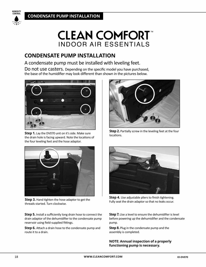
CONDENSATE PUMP INSTALLATION A condensate pump must be installed with leveling feet. Do not use casters. Depending on the specific model you have purchased, the base of the humidifier may look different than shown in the pictures below.
Step 1. Lay the DV070 unit on it's side. Make sure the drain hole is facing upward. Note the locations of the four leveling feet and the hose adaptor.
Step 2. Partially screw in the leveling feet at the four locations.
Step 3. Hand tighten the hose adaptor to get the threads started. Turn clockwise.
Step 4. Use adjustable pliers to finish tightening. Fully seat the drain adaptor so that no leaks occur.
Step 5. Install a sufficiently long drain hose to connect the drain adaptor of the dehumidifier to the condensate pump reservoir using field-supplied fittings.
Step 6. Attach a drain hose to the condensate pump and route it to a drain.
Step 7. Use a level to ensure the dehumidifier is level before powering up the dehumidifier and the condensate pump.
Step 8. Plug in the condensate pump and theassembly is completed.
NOTE: Annual inspection of a properly functioning pump is necessary.
WWW.CLEANCOMFORT.COM 19
WARRANTY
IO-DV070 IO-DV070
Limited Warranty
Daikin North America LLC (“Daikin”) warrants as follows: the Clean Comfort dehumidifier (“Product”) will be free of material defects in workmanship or materials for a period of five (5) years following the date of purchase of such Product by the original consumer purchaser (“Customer”).
Limitation of Liability. Customer’s sole and exclusive remedy under the above limited warranty, and any implied warranties, and Daikin’s entire liability thereunder, shall be for Daikin to provide a repaired or replacement Product or component of the Product (“Component(s)”), at the sole option of Daikin. Refrigerant, piping, supplies, transportation costs, labor costs incurred in deinstalling any defective Product or Components, or installing the repaired or replacement Product or Components, are not included. This disclaimer and exclusion shall apply even if the express warranty herein fails of its essential purpose. Customer acknowledges that no representative of Daikin or any of its affiliates or resellers is authorized to make any representation or warranty on behalf of Daikin or any of its affiliates or resellers that is not in this warranty. IN NO EVENT SHALL DAIKIN, IN CONNECTION WITH THE DESIGN, SALE, INSTALLATION, USE, REPAIR, REPLACEMENT OR PERFORMANCE OF ANY PRODUCT OR COMPONENTS, OR WRITTEN MATERIAL PROVIDED THEREWITH, BE LIABLE, WHETHER FOR BREACH OF WARRANTY OR OTHER CONTRACT BREACH, NEGLIGENCE OR OTHER TORT, OR ON ANY OTHER LEGAL THEORY, FOR ANY SPECIAL, INDIRECT, COLLATERAL OR CONSEQUENTIAL DAMAGES OF ANY KIND. Some states and provinces do not allow the exclusion or limitation of incidental or consequential damages, so the above exclusion may not apply to you.
Other Warranties. THE ABOVE LIMITED WARRANTY IS THE SOLE AND EXCLUSIVE EXPRESS WARRANTY PROVIDED WITH RESPECT TO THE PRODUCT AND ITS COMPONENTS, AND DAIKIN HEREBY LIMITS THE DURATION OF ALL IMPLIED WARRANTIES, INCLUDING, WITHOUT LIMITATION, THE IMPLIED WARRANTIES OF MERCHANTABILITY AND FITNESS FOR A PARTICULAR PURPOSE, TO THE DURATION OF THE ABOVE LIMITED WARRANTY. Some states and provinces do not allow limitations on how long an implied warranty lasts, so the above limitation may not apply to you.
Warranty Limitations. The foregoing limited warranty extends only to a Customer, and the Customer will not be entitled to any remedy hereunder if he or she attempts to assign or transfer this warranty. A “defect” under the terms of this limited warranty shall not include problems resulting from Customer’s or Customer’s employees’, agents’, invitees’ or a third party’s misuse, improper installation, improper design of any system in which the Product is included, abuse, lack of normal care, failure to follow written instructions, tampering, improper repair, or freezing, corrosion, acts of nature or other causes not arising
out of defects in workmanship or material. If a Product or Component is replaced while under warranty, the applicable limited warranty period shall not be extended beyond the warranty time period remaining on the original Product or Component. This limited warranty does not cover any costs related to changes to a Product or Component that may be required by any codes, laws, or regulations that may become effective after initial purchase of the Product by Customer.
Customer Responsibilities. In order to make a warranty claim, the Customer should call Daikin Consumer Affairs at 1-855-239-2665, which will then arrange for Product or Component repair or replacement. Warranty claims must be made during customary, daytime working hours. As further conditions to obtaining warranty coverage hereunder, the Customer must present forms of invoices evidencing proof of purchase of a Product and return the Product to Daikin if Daikin so requests. If the invoice presented does not clearly indicate the date of initial purchase by a Customer, the applicable Product’s date of manufacture shown on the Product’s rating plate will be used instead of the date of initial purchase for the purpose of calculating the commencement of the applicable warranty period. Repaired or replacement Products or Components must be provided by Daikin or a servicer authorized by Daikin. If the Product must be shipped to Daikin, Customer shall be solely responsible for properly packaging the Product, for all freight charges, and for all risk of loss associated with shipment.
Miscellaneous. If any term or condition of this Limited Warranty is found by a court of competent jurisdiction to be invalid, illegal or otherwise unenforceable, the same shall not affect the other terms or conditions hereof or thereof or the whole of this Limited Warranty. Any delay or failure by Daikin to exercise any right or remedy will not constitute a waiver of Daikin to thereafter enforce such rights.
This warranty gives you specific legal rights, and you may also have other rights which vary from state to state or province to province.
DAIKIN NORTH AMERICA LLC4201 Lien Rd. Madison, Wisconsin 53704
1-855-239-2665
For questions regarding warranty, service, or spare
parts for this Clean Comfort product please contact
your installing contractor or a local Daikin representative.
For technical support, please call 1-855-239-2665.
HUMIDITY CONTROL
WWW.CLEANCOMFORT.COMIO-DV070 2/14
Our continuing commitment to quality products may mean a change in specifications without notice.
© 2014 DAIKIN NORTH AMERICA LLC Houston, Texas • USA
Email: [email protected] • 1-855-239-2665
Notes:


