

University of Southern Denmark
Design, analysis, and impacts of sinusoidal LC filter on pulsewidth modulated inverter fed-induction motor drive
Mishra, Prasun; Maheshwari, Ramkrishan
Published in:IEEE Transactions on Industrial Electronics
DOI:10.1109/TIE.2019.2913824
Publication date:2020
Document version:Accepted manuscript
Citation for pulished version (APA):Mishra, P., & Maheshwari, R. (2020). Design, analysis, and impacts of sinusoidal LC filter on pulsewidthmodulated inverter fed-induction motor drive. IEEE Transactions on Industrial Electronics, 67(4), 2678-2688.https://doi.org/10.1109/TIE.2019.2913824
Go to publication entry in University of Southern Denmark's Research Portal
Terms of useThis work is brought to you by the University of Southern Denmark.Unless otherwise specified it has been shared according to the terms for self-archiving.If no other license is stated, these terms apply:
• You may download this work for personal use only. • You may not further distribute the material or use it for any profit-making activity or commercial gain • You may freely distribute the URL identifying this open access versionIf you believe that this document breaches copyright please contact us providing details and we will investigate your claim.Please direct all enquiries to [email protected]
Download date: 17. Mar. 2022
IEEE TRANSACTIONS ON INDUSTRIAL ELECTRONICS
Abstract— Squirrel cage induction motor (SQIM) fed by a pulse width modulated voltage source inverter (VSI) is subjected to voltage and current surges. It may cause additional losses in the motor, insulation failure, high bearing current, and electromagnetic interference. To mitigate these problems, sinusoidal LC filter is placed at the ac-side of the VSI. This paper proposes a new methodology to design the filter. In this method, the filter inductance is chosen based on the maximum ripple in the inverter ac-side current and the voltage drop across the filter inductor, and the filter capacitor is chosen based on the steady-state reactive power demand of the SQIM. The effects of the designed filter on the switch current, losses in the drive, temperature of the dc-link capacitor, dv/dt at the motor terminal, stator flux, and air-gap torque of the SQIM are discussed. The performance of the drive with the filters, designed by the proposed method and the standard method, are experimentally tested on a two-level Silicon carbide (SiC) VSI fed SQIM and comparative analysis is carried out. The impact of the designed filter on the drive is also shown when the neutral point of the filter capacitors is connected with the mid-point of the dc-link. The stability of the closed-loop controlled SQIM drive with the proposed filter, and simulation results are presented to verify its performance.
Index Terms— Sinusoidal LC filter, squirrel-cage induction motor drive, variable-frequency operation.
I. INTRODUCTION
ILICON carbide (SiC) power metal–oxide–semiconductor
field–effect transistor (MOSFET) based pulse width
modulated voltage source inverter (VSI) has seen better
technological prospects as compared to silicon (Si) power
MOSFET based VSI [1]−[4]. These are also used in constant
speed drives (CSD) and adjustable speed drives (ASD) [5]−[7].
As SiC MOSFET has the potential of fast switching transitions,
it may aggravate the problems like insulation failure, high
bearing current, severe electromagnetic interference (EMI), and
a substantial amount of core losses in the VSI fed squirrel-cage
induction motor (SQIM) drive [8]−[12].
To mitigate these problems, several filter configurations are
proposed in the literature [13], [14]. Among those, the most
popular configuration is three-phase second-order low-pass
sinusoidal LC filter [15]−[16]. There are many methodologies
available in the literature [17]−[21] to design the series filter
inductor and the shunt filter capacitor. In [17], a three-phase LC
filter with a band-reject circuit is optimally designed to
minimize the cost of the filter with constraints like suppression
Manuscript received December 09, 2018 and revised March 14, 2019; accepted April 07, 2019.
The authors are with the department of Electrical Engineering, Indian Institute of Technology Delhi, New Delhi, India (e-mail: [email protected], [email protected].
of the switching harmonics and deviation of the fundamental
output voltage. However, importance is given on the design of
the filter inductor, while the effects of filter capacitance on ASD
are ignored. An improved Genetic Algorithm optimization
technique is used in [18] to select the filter inductance and the
filter capacitance. In this method, the objective function is to
minimize the harmonic distortion of the phase currents and
phase voltages, the voltage drop across the inductor, the losses
in the filter elements, and the cost of the filter. However, the
effects of filter on power losses, cost, and size of the VSI are
neglected. Similarly, an optimum design of the RLC filter using
fuzzy logic is proposed in [19]. In this method, the switching
time lag of the inverter and its operation in the overmodulation
region are additionally considered in the design of the filter. The
current through the filter capacitor is restricted to 10% of the
rated current of the motor at its fundamental frequency to design
the filter capacitor. However, the effect of the filter capacitor
on the VSI is not discussed which significantly affects the
performance of the drive. Another approach of designing
sinusoidal LC filter for SiC VSI fed ac motor drive is used in
[21], where the filter inductance is calculated by considering the
voltage drop across the filter inductor at a certain percentage of
the maximum operating fundamental frequency and the rated
motor current. However, the design methodologies of [17]−[21]
treat the filter elements separately and do not include the motor
as a part of the system. Moreover, these procedures do not
consider the effects of filter capacitance on the drive. As the
filter capacitor may be used to supply the reactive power
demand of the SQIM [15], it may reduce the inverter ac-side
current. This may, in turn, reduce the power losses in the drive.
Therefore, the effects of the filter capacitor on the drive have
been considered in this paper.
In this paper, the filter capacitance has been calculated based
on the reactive power demand of the SQIM at steady-state. The
filter inductance is selected by considering two aspects like the
ripple content in the inverter ac-side current and the voltage
drop across the filter inductor. A preliminary discussion of the
proposed method was presented in [23], where no experimental
results were presented, and the impacts of the filter on different
parts of the drive were not explored. The work of [23] has been
extended in this paper, and the performance of the drive with
the filters designed by the standard method (SM) and the
proposed method (PM) has been verified at different operating
points for an in-house designed and developed SiC MOSFET
based three-phase VSI fed SQIM.
The following impacts of the filters designed by PM and SM
are discussed, and comparative analysis is carried out:
1) The switch current of the VSI and the cumulative power
loss in the drive with two filters have been discussed.
2) The effects of the two filters on the dc-link capacitor of the
VSI have been discussed.
Design, Analysis, and Impacts of Sinusoidal LC Filter on Pulse Width Modulated Inverter Fed Induction Motor Drive
Prasun Mishra, Member, IEEE and Ramkrishan Maheshwari, Senior Member, IEEE
S
This is the author's version of an article that has been published in this journal. Changes were made to this version by the publisher prior to publication.The final version of record is available at http://dx.doi.org/10.1109/TIE.2019.2913824
Copyright (c) 2019 IEEE. Personal use is permitted. For any other purposes, permission must be obtained from the IEEE by emailing [email protected].

IEEE TRANSACTIONS ON INDUSTRIAL ELECTRONICS
3) The stator flux of SQIM, dv/dt at the motor-input terminals,
and the pulsating electromagnetic air-gap torque of the
SQIM with two filters have been discussed.
4) The common-mode voltages of the SQIM drive with two
filters have been discussed when the neutral point of the
filter capacitor is connected with the mid-point of dc-link.
This paper is organized as follows. The methodologies of
designing LC filters by SM and PM are elaborated in Section
II. The impacts of two filters, designed by SM and PM, on the
VSI fed SQIM drive are theoretically analyzed in Section III
and verified through experimental results in Section IV. The
stability of the closed-loop motor drive with the filter at an
operating point is briefly discussed and MATLAB simulation
results are presented to verify its steady-state and dynamic
performance in Section V followed by conclusion in Section
VI.
II. METHODS OF LC FILTER DESIGN FOR VSI FED SQIM
In this paper, three-phase second-order low-pass sinusoidal
LC filter has been designed for a SiC discrete MOSFET based
three-phase two-level VSI fed 3 hp, 415 V, 4.6 A, four-pole, 50
Hz, star connected, three-phase SQIM as shown in Fig. 1. Here,
Rf and Lf are the per-phase ac resistance and inductance of the
filter inductor, respectively. Rc, and Cf are the per-phase ac
resistance and capacitance of the filter capacitor, respectively.
The calculation of the filter inductance is common in both SM
and PM. However, the calculation of the filter capacitance is
different in SM and PM, which is discussed in the following
sub-sections.
SQIM
fR fL
cR
fC
invRi
invYi
invBi
smRi
smYi
smBi
dci
dc1C
ini
ci
dc2C
o
n
dcV
1S3S 5S
2S4S 6S
Fig. 1. VSI fed three-phase SQIM with sinusoidal LC filter.
A. Calculation of Filter Inductance (Lf) in SM and PM
The magnitude of Lf has been calculated considering two
design criteria [20]−[22]. The first criterion [20] is that the
value of switching ripple current (Δiinv) through Lf is within
15−25 % of the peak value of the inverter ac-side current (iinv).
iinv is assumed as the rated current (ism) of SQIM. The second
criterion [21], [22] is that the voltage drop (vL) across Lf at rated
iinv and rated frequency (fs) should not exceed 3% of the rated
motor voltage (vsm). However, the selection of Lf is basically a
design trade-off between the maximum current ripple and the
size of Lf. The expressions of Δiinv and vL are given by
dc
sw f8inv
Vi
f L
(1)
22
L inv f s f2v i R f L
(2)
where Vdc is the dc-link voltage and fsw is the switching
frequency. The value of Δiinv is considered as 20% of the peak
value of rated iinv. The calculated value of Lf is 1.15 mH for Vdc
= 600 V and fsw = 50 kHz. However, Lf of 1.2 mH has been used
in experiment which is closer to the calculated value. vL across
Lf (Lf =1.2 mH, Rf = 0.3 Ω) is 0.93 % at vsm =239.60 V, iinv = 4.6
A, and fs = 50 Hz.
B. Calculation of Filter Capacitance (Cf) in SM
Fig. 2 depicts the power circuit [22] which has been
considered to calculate the filter parameters in SM where Lf, Cf,
stator and rotor leakage inductance (Lls =14.1 mH and Llr =14.1
mH) of SQIM are only considered to find out the Thevenin
equivalent inductance (Leq) as these inductances play major role
at higher frequency than the magnetizing inductance (Lm= 267
mH) of the SQIM. vinv is the inverter output voltage.
invv smvfL
fClrL
lsL
Fig. 2. Power circuit considered in SM to calculate filter parameters.
The expression of effective resonance frequency (fres) is
given by
f lres
f leq f
1 1
22 f
L Lf
L L CL C
(3)
where, Ll is the summation of Lls and Llr. Once the value of Leq
is calculated, the value of Cf can also be calculated by (3) for a
chosen fres. In order to avoid the resonance frequency
oscillation, it is advisable to choose fres below the switching
frequency and well above the fundamental frequency of the
pulse width modulated inverter output voltage [24]. For fsw of
50 kHz and fs of 50 Hz, fres is chosen as 5 kHz to reduce the size
of Cf. The value of Cf is calculated as 0.845 µF. However, Cf of
1.25 µF is used in the experiment which is closer to the
calculated value and fres is recalculated as 4195.90 Hz. In SM,
the filter is only responsible for filtering high-frequency
components and the effects of Cf on the ac drive are not
explored. However, the value of Cf in PM has been calculated
by considering its impacts on the ac drive as discussed below.
C. Calculation of Filter Capacitance in PM
The basic motivation behind PM is that the reactive power
demand of the SQIM has to be supplied by Cf and only the
active power demand has to be supplied from the VSI. The
reactive power is mainly responsible for energizing the
magnetic core of the SQIM to develop the required air-gap flux
and its demand is almost same irrespective of no-load or full-
load operation. As the reactive power demand is higher as
compared to the active power demand of the SQIM at 50 Hz
and no-load operation, the no-load power factor (p.f) of the
SQIM is poor as compared to its full-load p.f. The reactive
power demand at 50 Hz is almost fixed irrespective of load.
Therefore, reactive elements of per-phase steady-state no-load
equivalent circuit of the motor and filter are only considered in
PM for equalizing the reactive power demand of SQIM and the
reactive power supplied by Cf. Fig. 3 depicts the power circuit
which has been considered to calculate the filter parameters in
PM where Lf, Lls, and Lm have been considered. vsm is the stator
phase voltage of the SQIM.
This is the author's version of an article that has been published in this journal. Changes were made to this version by the publisher prior to publication.The final version of record is available at http://dx.doi.org/10.1109/TIE.2019.2913824
Copyright (c) 2019 IEEE. Personal use is permitted. For any other purposes, permission must be obtained from the IEEE by emailing [email protected].

IEEE TRANSACTIONS ON INDUSTRIAL ELECTRONICS
In PM, the active power demand of the SQIM and the
reactive power demand of Lf are supplied from the VSI, while
the reactive power demand of the SQIM is supplied from the
filter capacitor, i.e.,
22 sm
sm s fs m ls
22
vv f C
f L L
(4)
The value of Cf is deduced from (4) and is given by
f 2 2
s m ls
1
4C
f L L
(5)
Fig. 3. Power circuit considered in PM to calculate filter parameters. The value of Cf is calculated as 35.99 µF when fs and Lm are 50
Hz and 267 mH, respectively. However, Cf of 40 µF is used in
the experiment which is closer to the calculated value. The fres
in PM is calculated as 741.73 Hz for the chosen filter inductance
and filter capacitance. The calculated values of Lf, Cf, and fres in
PM and SM have been tabulated in Table I.
TABLE I PARAMETERS OF FILTER OBTAINED BY SM AND PM
Method fs (Hz) fsw (kHz) fres (Hz) Lf (mH) Cf (µF)
SM 50 50 4195.90 1.2 1.25
PM 50 50 741.73 1.2 40
The 40 µF filter capacitor (EUROPTRONIC MPX2) in PM
is 32 times higher than the 1.25 µF filter capacitor (CTR
MPPRRB) in SM. 40 µF capacitor in PM is realized by
connecting four 10 µF capacitors in parallel. However, parallel
connection of capacitors reduces effective equivalent series
resistance (ESR) of the capacitor bank and also increases its
current rating. The volume and unit price of 1.25 µF capacitor
are 13.125 cm3 and 0.24 USD, respectively. The volume and
unit price of 40 µF capacitor bank are 216 cm3 and 2.52 USD,
respectively. The 40 µF capacitor bank can also be replaced by
a single 40 µF capacitor. The volume and unit price (minimum
order of 100 units) are different if these capacitors are
manufactured by VISAY and EPCOS. The volume and unit
price of a 2 µF ac film filter capacitor (MKP1847520254K2)
are 7.39 cm3 and 2.75 USD, respectively. The volume and unit
price of a 40 µF ac film filter capacitor (B32796E2406K) are
56.70 cm3 and 16.11 USD, respectively. However, the larger
volume and higher cost of the filter capacitor in PM than SM
are compensated by following long-run favorable outcomes as
discussed below.
III. IMPACTS OF FILTER (THEORETICAL ANALYSIS)
The LC filter designed by PM has significant impacts on the
VSI fed SQIM drive in comparison with the filter designed by
SM. These impacts are discussed in the following sub-sections
with MATLAB simulation results. The fundamental frequency
(fs : 10−50 Hz) of the motor line-line voltage (vsm(L) : 83−415V)
and the load torque (ml : 0−10 Nm) of the SQIM drive with filter
have been varied in open loop v/f control.
A. Reduction of ac-side current (iinv) of VSI
In PM and SM, the magnitude of iinv at different frequencies
and load torques have been plotted in Fig. 4. The magnitude of
iinv is significantly reduced in PM than that of SM from
medium-frequency to the high-frequency operation of the
SQIM. In low-frequency, the filter capacitor does not fully
compensate the reactive power demand of v/f controlled SQIM
as the frequency and the voltage of the filter capacitor are
reduced proportionally. However, the magnitude of iinv at all
operating frequencies is always lesser in PM than SM. For
example, it is in the range of 1.45 A to 3.59 A in PM and 2.89
A to 4.53 A in SM while ml is varied from 0 Nm to 10 Nm at
50 Hz.
(b)(a)
Fig. 4. Magnitude of iinv at variable ml and fs in (a) SM, (b) PM.
For a balanced ac-side phase current of the VSI, the root
mean square (rms) current through MOSFET (Irms,M) and anti-
parallel diode (Irms,D) [25] are given by
armsrms,M
8 cos1
2 3
mII
(6)
armsrms,D
8 cos1
2 3
mII
(7)
where, Irms is the rms value of iinv, ma is the modulation index,
and cos(ϕ) is the p.f. As the value of Irms for same ma is lesser in
PM than that of SM as shown in Fig. 4, the current through the
switch (MOSFET and antiparallel diode) is lesser in PM than
SM. The reduced ac-side current (iinv) of the VSI in PM than
that of SM also reduces the cumulative loss in the VSI and filter
and thus it improves the efficiency of the whole drive.
Experimental results are presented in Section IV.
B. Reduction of rms current ripple and temperature rise of dc-link capacitor
For same ma, Irms of iinv is reduced and cos(ϕ) is increased in
PM than SM. The expression of rms value of the dc-link
capacitor-current ripple (ic,rms) is given by [26]
2
c,rms rms
3 3 92 cos
4 16a ai I m m
(8)
Therefore, the variation of ic,rms in PM and SM are calculated
by (8) and are shown in Fig. 5. The magnitude of ic,rms is
significantly reduced in medium-frequency and high-frequency
region as compared to the low-frequency region. However, its
magnitude at all fundamental frequencies is lesser in PM than
that of SM. For example, it is in the range of 0.73 A to 1.81 A
in PM and 1.50 A to 2.31 A in SM while ml is varied from 0
Nm to 10 Nm at 50 Hz.
invv fLfC
mLls
L
smv
This is the author's version of an article that has been published in this journal. Changes were made to this version by the publisher prior to publication.The final version of record is available at http://dx.doi.org/10.1109/TIE.2019.2913824
Copyright (c) 2019 IEEE. Personal use is permitted. For any other purposes, permission must be obtained from the IEEE by emailing [email protected].

IEEE TRANSACTIONS ON INDUSTRIAL ELECTRONICS
(b)(a)
Fig. 5. ic,rms at variable ml and fs in (a) SM, (b) PM.
Six BLC polypropylene board mount 16 µF film capacitor
(Part No: BLC160J901B4C) connected in series-parallel
combination have been used as dc-link capacitors. Two
capacitors (Cd) are connected in series and three such
configurations are connected in parallel to form total dc-link
capacitance (Cdc) where Cdc=1.5Cd. The parameters of the
capacitors are given in [27]. The rms ripple current (icrms)
through an individual capacitor (Cd) is the 1/3rd time of the
current flows through the equivalent capacitor (Cdc) and the
temperature difference (ΔT) between the ambient (Ta) and the
core (Tc) of each capacitor (Cd) is calculated by
2
c a crms,f f f T T T i ESR (9)
where θf is the total thermal resistance, ESRf is the ESR of the
capacitor, and icrms,f is the ripple current through the capacitor
at the frequency (f). Expected lifetime of the capacitor for same
operating voltage mainly depends on the core temperature of
the dc-link capacitor as given by [28]
r c
10p r 2
n T T
a
r
VL L
V
(10)
where, Lp and Lr are the predicted and the rated lifetime of the
capacitor, respectively. Tc and Tr are the temperature in Kelvin
at the operating condition and rated condition, respectively. Va
and Vr are the voltages at the operating condition and rated
condition, respectively. According to (9) and (10), lesser high-
frequency ic,rms in PM than SM also reduces the temperature rise
and experimental results at the same operating point are
presented in Section IV for comparison.
C. Reduction of distortions in stator-flux of SQIM
The filter, having lower fres in PM than SM, highly attenuates
the harmonic components of vinv and produces less distorted vsm
and ism. Therefore, the less distorted alpha (α) and beta (β)
component of vsm (vsα, vsβ) and ism (isα, isβ) produce less distorted
alpha (α) and beta (β) component of stator flux (λsα, λsβ) [29] as
given by
sx sx sx , ,sv R i dt x
(11)
where Rs is the per phase stator resistance of the SQIM. In
Section IV, it is experimentally verified and compared at the
same operating point in an open-loop v/f controlled SQIM drive
with filters designed by SM and PM.
D. Reduction of air-gap torque pulsation of SQIM
The harmonic voltages produce harmonic currents as well as
harmonic fluxes. The interactions between fundamental and
harmonic components of fluxes and currents produce pulsating
air-gap torque in SQIM. It deteriorates the performance of the
SQIM and creates mechanical vibration and noise. In [30], the
expression of pulsating air-gap torque of SQIM drive is derived
by considering all kind of harmonics which may be present in
the balanced system. The filtered inverter voltage has jth order
positive, kth order negative and pth order zero sequence
harmonic components with respect to its fundamental
component depending on the dead time of the VSI, cutoff
frequency, and gain of the filter. Here, j = 6q+1, k = 6q-1, and
p = 3q for q = 0, 1, 2, 3 and so on. The dc component of the air-
gap torque [30] is given by
sm1 sm1e dc 1
2cos
3 2
v iPT T
(12)
where ϕ1 is the phase angle between the fundamental
component of motor phase voltage (vsm1) and motor phase
current (ism1). The air-gap torque equation with negative
sequence harmonics [30] is given by
e dc j+1Neg jcos( j 1 )t t T T t
(13)
where sm1 smj smj sm1j+1Neg
2 P
3 2 j
v i v iT
The air-gap torque equation with positive sequence harmonics
[30] is given by
e dc k-1Pos kcos( 1 )t t T T k t
(14)
where sm1 smk smk sm1k-1Pos
2
3 2 k
v i v iPT
At very high frequency, the contribution of the terms having j
and k in the denominator of negative (Tj+1Neg) and positive
sequence (Tk-1Pos) torque components in (13) and (14),
respectively are negligible in the air-gap torque equation.
Therefore, the air-gap torque is considered as the product of the
stator-current and fundamental component of stator-flux. As the
fundamental current and the fundamental voltage profile of the
SQIM are improved in the PM than SM due to higher filter
capacitance, the air-gap torque profile is improved in PM. In
Section IV, it is experimentally verified and compared at the
same operating point in an open-loop v/f controlled SQIM drive
with the filters designed by SM and PM.
E. Reduction of common mode voltage (special case)
If the neutral point (n) of the filter capacitors is connected
with the mid-point (o) of the dc-link, the expression of
common-mode voltage (vcm) is derived in [31] and is given by
sRg sYg+ sBgcm c o o og
f
1 1
3 3
v v vv R i i dt v
C
(15)
where vog is the voltage between the supply ground (g) and mid-
point (o) of dc-link. io is the total current flowing from “n” to
“o”. vsRg, vsYg, and vsBg are the stator voltages of phase R, Y, and
B w.r.t ground, respectively. It is clear from (15) that the
magnitude of vcm depends on the filter parameters (Rc, Cf) and
io, and it is experimentally verified and compared in Section IV.
F. Reduction of dv/dt at motor terminal
The time derivative of stator voltage is inversely proportional
to the square root of filter capacitance of the LC filter [32] and
is given by
This is the author's version of an article that has been published in this journal. Changes were made to this version by the publisher prior to publication.The final version of record is available at http://dx.doi.org/10.1109/TIE.2019.2913824
Copyright (c) 2019 IEEE. Personal use is permitted. For any other purposes, permission must be obtained from the IEEE by emailing [email protected].

IEEE TRANSACTIONS ON INDUSTRIAL ELECTRONICS
sm dc
eq f
dv V
dt L C (16)
Higher filter capacitance in PM than that of SM is also
beneficial from the dv/dt aspect, as it reduces the rate of rise of
the motor terminal voltage and it is experimentally verified and
compared in Section IV.
IV. IMPACTS OF FILTER (EXPERIMENTAL RESULTS)
All the experiments have been performed on SiC MOSFET
based VSI fed SQIM without and with LC filter designed by
PM and SM, as shown in Fig. 6. The iron powder toroidal core
and ac polypropylene film capacitors have been used to design
the LC filters. The open loop v/f control of the SQIM with space
vector pulse width modulation (SVPWM) technique has been
implemented in TMS320F28335 digital signal controller
(DSC).
(b)(a) (c)
Fig. 6. (a) SiC MOSFET based VSI, (b) filter inductors and capacitors and, (c) TMS320F28335 DSC and signal conditioning circuits.
The values of fsw and Vdc are 50 kHz and 600 V, respectively.
The values of ma and dead-time of the VSI are set to 1 and 1 µs,
respectively. The frequency reference of the v/f controlled drive
with and without filter is set to 50 Hz. The performance of the
drive with LC filters designed by SM and PM have been
compared and analyzed in the following sub-sections.
A. Reduction of ac-side current (iinv) of VSI
Figs. 7−9 and Figs. 10−12 show the line current (ism and iinv)
and the line-line voltage (vsm(L) and vinv(L)) of the motor and
inverter at 50 Hz with light and full load torque. The
experimental results as shown in Figs. 7−12 have been analyzed
by Fast Fourier Transform (FFT) and the rms value of the
fundamental currents and voltages as well as the percentage (%)
total harmonic distortion (THD) have been tabulated in Table
II−III. The oscillations in iinv of Fig. 12 near about fres (741.73
Hz) is due to the resonance of LCL network. The magnitude of
the fundamental vinv(L) is reduced due to dead-time effect [33].
The magnitude of iinv with light load operation is 1.737 A
without filter, 1.612 A, and 0.7298 A with the filters, designed
by SM and PM, respectively. The magnitude of iinv with full
load operation is 5.063 A without filter, 4.756A, and 4.163 A
with filters, designed by SM and PM, respectively.
(a) (b)
sm(L)vsmi2A/div 500V/div
5 ms/div 5 ms/div
Fig. 7. Experimental results at 50 Hz without filter and light load, (a) ism
(2A/div), (b) vsm(L) (500V/div).
(a) (b)
inv(L)v
sm(L)vinvi
smi2A/div 500V/div
5 ms/div5 ms/div
Fig. 8. Experimental results at 50 Hz with filter and light load in SM, (a)
ism, iinv (2A/div), (b) vsm(L), vinv(L) (500V/div).
(a) (b)
inv(L)v
sm(L)vinvi
smi
2A/div 500V/div5 ms/div
5 ms/div
Fig. 9. Experimental results at 50 Hz with filter and light load in PM, (a) ism, iinv (2A/div), (b) vsm(L), vinv(L) (500V/div).
(a) (b)
sm(L)v5A/div 500V/divsmi
5 ms/div 5 ms/div
Fig. 10. Experimental results at 50 Hz without filter and full load, (a) ism
(5A/div), (b) vsm(L) (500V/div)
TABLE II
COMPARISON WITH LIGHT LOAD TORQUE AT 50 Hz
Method iinv (A) ism (A) vinv (L) (V) vsm (L) (V)
No filter 1.737
(9.18%)
1.737
(9.18%)
338.3
(75.27%)
338.3
(75.27%)
SM 1.612
(17.85%)
1.689
(10.62%)
334.7
(73.62%)
330.3
(4.51%)
PM 0.7298
(37.76%)
1.64
(9.04%)
324.8
(75.26%)
322.7
(3.72%)
(a) (b)
inv(L)v
sm(L)vinvi
smi
5A/div 500V/div
5 ms/div
5 ms/div
Fig. 11. Experimental results at 50 Hz with filter and full load in SM, (a)
ism, iinv (5A/div), (b) vsm(L), vinv(L) (500V/div).
(a) (b)
inv(L)v
sm(L)vinvi
smi
5A/div 500V/div5 ms/div
5 ms/div
Fig. 12. Experimental results at 50 Hz with filter and full load in PM, (a) ism, iinv (5A/div), (b) vsm(L), vinv(L) (500V/div).
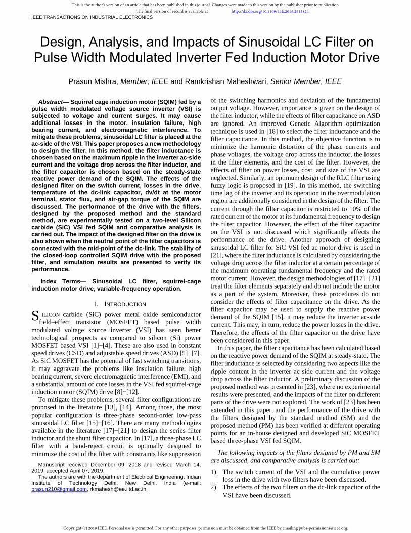
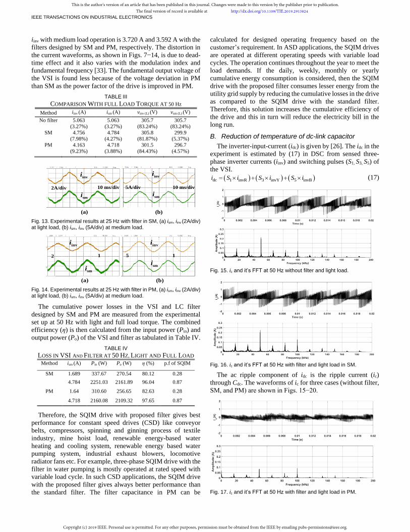
The waveforms of iinv and ism at 25 Hz with light and medium
load torque operation are shown in Figs. 13−14. The magnitude
of iinv with light load operation is 1.484 A and 1.052 A with the
filters designed by SM and PM, respectively. The magnitude of
This is the author's version of an article that has been published in this journal. Changes were made to this version by the publisher prior to publication.The final version of record is available at http://dx.doi.org/10.1109/TIE.2019.2913824
Copyright (c) 2019 IEEE. Personal use is permitted. For any other purposes, permission must be obtained from the IEEE by emailing [email protected].
IEEE TRANSACTIONS ON INDUSTRIAL ELECTRONICS
iinv with medium load operation is 3.720 A and 3.592 A with the
filters designed by SM and PM, respectively. The distortion in
the current waveforms, as shown in Figs. 7−14, is due to dead-
time effect and it also varies with the modulation index and
fundamental frequency [33]. The fundamental output voltage of
the VSI is found less because of the voltage deviation in PM
than SM as the power factor of the drive is improved in PM.
TABLE III
COMPARISON WITH FULL LOAD TORQUE AT 50 Hz
Method iinv (A) ism (A) vinv (L) (V) vsm (L) (V)
No filter 5.063
(3.27%)
5.063
(3.27%)
305.7
(83.24%)
305.7
(83.24%)
SM 4.756
(7.98%)
4.784
(4.27%)
305.8
(81.87%)
299.9
(5.37%)
PM 4.163
(9.23%) 4.718
(3.88%)
301.5
(84.43%)
296.7
(4.57%)
invi
smi
(a) (b)
2A/div 5A/div10 ms/div 10 ms/div
invi
smi
Fig. 13. Experimental results at 25 Hz with filter in SM, (a) ism, iinv (2A/div) at light load, (b) ism, iinv (5A/div) at medium load.
(a) (b)
2 A / d i v5 A / d i v1 0 m s / d i v1 0 m s / d i v
invi
smi
invi
smi
Fig. 14. Experimental results at 25 Hz with filter in PM, (a) ism, iinv (2A/div) at light load, (b) ism, iinv (5A/div) at medium load.
The cumulative power losses in the VSI and LC filter
designed by SM and PM are measured from the experimental
set up at 50 Hz with light and full load torque. The combined
efficiency (η) is then calculated from the input power (Pin) and
output power (Po) of the VSI and filter as tabulated in Table IV.
TABLE IV
LOSS IN VSI AND FILTER AT 50 HZ, LIGHT AND FULL LOAD
Method ism (A) Pin (W) Po (W) η (%) p.f of SQIM
SM 1.689 337.67 270.54 80.12 0.28
4.784 2251.03 2161.89 96.04 0.87
PM 1.64 310.60 256.65 82.63 0.28
4.718 2160.08 2109.32 97.65 0.87
Therefore, the SQIM drive with proposed filter gives best
performance for constant speed drives (CSD) like conveyor
belts, compressors, spinning and ginning process of textile
industry, mine hoist load, renewable energy-based water
heating and cooling system, renewable energy based water
pumping system, industrial exhaust blowers, locomotive
radiator fans etc. For example, three-phase SQIM drive with the
filter in water pumping is mostly operated at rated speed with
variable load cycle. In such CSD applications, the SQIM drive
with the proposed filter gives always better performance than
the standard filter. The filter capacitance in PM can be
calculated for designed operating frequency based on the
customer’s requirement. In ASD applications, the SQIM drives
are operated at different operating speeds with variable load
cycles. The operation continues throughout the year to meet the
load demands. If the daily, weekly, monthly or yearly
cumulative energy consumption is considered, then the SQIM
drive with the proposed filter consumes lesser energy from the
utility grid supply by reducing the cumulative losses in the drive
as compared to the SQIM drive with the standard filter.
Therefore, this solution increases the cumulative efficiency of
the drive and this in turn will reduce the electricity bill in the
long run.
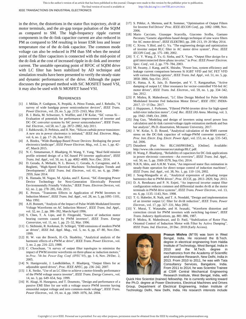
B. Reduction of temperature of dc-link capacitor
The inverter-input-current (idc) is given by [26]. The idc in the
experiment is estimated by (17) in DSC from sensed three-
phase inverter currents (iinv) and switching pulses (S1, S3, S5) of
the VSI.
dc 1 invR 3 invY 5 invBi S i S i S i (17)
Fig. 15. ic and it’s FFT at 50 Hz without filter and light load.
Fig. 16. ic and it’s FFT at 50 Hz with filter and light load in SM.
The ac ripple component of idc is the ripple current (ic)
through Cdc. The waveforms of ic for three cases (without filter,
SM, and PM) are shown in Figs. 15−20.
Fig. 17. ic and it’s FFT at 50 Hz with filter and light load in PM.
This is the author's version of an article that has been published in this journal. Changes were made to this version by the publisher prior to publication.The final version of record is available at http://dx.doi.org/10.1109/TIE.2019.2913824
Copyright (c) 2019 IEEE. Personal use is permitted. For any other purposes, permission must be obtained from the IEEE by emailing [email protected].

IEEE TRANSACTIONS ON INDUSTRIAL ELECTRONICS
The different frequency components of ic have been extracted
by FFT analysis. The ESR as well as θf have also been
calculated at different frequencies. The instantaneous
temperature rise in each dc-link capacitor is calculated by (9)
and tabulated in Table V. The magnitudes of different
frequency components of ic and the corresponding frequency
dependent ESR are reduced in PM than SM with light load and
with full load, respectively. Therefore, ΔT in Cd is less in PM
than SM and it may lengthen the lifetime of the dc-link
capacitor [27]−[28].
Fig. 18. ic and it’s FFT at 50 Hz without filter and full load.
TABLE V CALCULATED ΔT IN INDIVIDUAL CAPACITOR (Cd)
Load torque ΔT without filter ΔT in SM ΔT in PM
Light load 0.0026 °C 0.0026 °C 0.0006 °C
Full load 0.0154 °C 0.0162 °C 0.0127 °C
Fig. 19. ic and it’s FFT at 50 Hz with filter and full load in SM.
Fig. 20. ic and it’s FFT at 50 Hz with filter and full load in PM.
C. Reduction of distortion in stator-flux of SQIM
In the experimental setup, the stator-flux of SQIM has been
estimated using (11) from the sensed stator-voltages and stator-
currents. The alpha and beta components of the estimated
stator-flux vector in SM and PM are plotted in Figs. 21−22 for
light load and full load operation of SQIM. The distortion in the
stator-flux trajectory has been reduced in PM than SM and
therefore improves the stator-flux of the SQIM. It could be seen
from Table II−III that the % THD of the stator-voltage and
stator-current are also reduced.
Fig. 21. Stator-flux trajectory of SQIM with light load in (a) SM, (b) PM.
Fig. 22. Stator-flux trajectory of SQIM with full load in (a) SM, (b) PM.
D. Reduction of air-gap torque pulsation of SQIM
The air-gap torque of the SQIM [30] in the experiment is
estimated offline from the stator currents and the fundamental
stator flux, where the stator-voltages and stator-currents of
SQIM are sensed from the experimental setup. The estimated
air-gap torque and the zoomed version of its frequency
spectrums are shown in Figs. 23−24.
Fig. 23. Air-gap torque and its FFT with light load in, (a) SM, (b) PM.
Fig. 24. Air-gap torque and its FFT with full load in, (a) SM, (b) PM.
The torque ripple over one cycle of fs is calculated by
subtracting the average of estimated torque from the actual
estimated torque, and those are tabulated in Table VI-VII. It is
found that the dominant frequency components of the air-gap
torque have been comparatively reduced in PM than SM.
Therefore, the torque pulsation has been comparatively reduced
in PM than SM. The presence of low order frequency
(a) (b)
(a) (b)
(a) (b)
(a) (b)
This is the author's version of an article that has been published in this journal. Changes were made to this version by the publisher prior to publication.The final version of record is available at http://dx.doi.org/10.1109/TIE.2019.2913824
Copyright (c) 2019 IEEE. Personal use is permitted. For any other purposes, permission must be obtained from the IEEE by emailing [email protected].

IEEE TRANSACTIONS ON INDUSTRIAL ELECTRONICS
components in voltage and current of the inverter, as well as the
motor, is due to the dead-time of the inverter [33].
TABLE VI
COMPARISON OF DIFFERENT COMPONENTS IN TORQUE
Load Light load Full load
Frequency 300 Hz 50050 Hz 300 Hz 50050 Hz
SM 0.4117 Nm 0.3117 Nm 0.3200 Nm 0.3250 Nm
PM 0.0896 Nm 0.3103 Nm 0.2111 Nm 0.3281 Nm
TABLE VII
COMPARISON OF AVERAGE TORQUE AND TORQUE RIPPLE
Load Light load Full load
Torque Average
torque
Torque
ripple
Average
torque
Torque
ripple
SM 0.9504 Nm 0.5138 Nm 9.9254 Nm 0.5576 Nm
PM 1.008 Nm 0.4038 Nm 10.178 Nm 0.4142 Nm
E. Reduction of common mode voltage (special case)
The effect of the higher value of filter capacitance on vcm in
PM than SM has been shown through experimental results. In
the experiment, the three-phase stator voltages of the SQIM
w.r.t supply ground have been sensed and the common mode
voltage (vcm) has been calculated by (15). The peak-peak vcm is
found 140 V and 164 V in PM and SM, respectively as shown
in Fig. 25. However, the harmonics present in io in such filter
configuration [31] increases the ripple content in iinv as shown
in Fig. 26 and thus increases the ripple content in ic.
(a) (b)
Fig. 25. Common mode voltage (vcm) w.r.t ground in (a) SM, (b) PM.
(a) (b)
5A/div 10ms/diviinv
ism
5A/div 10ms/diviinv
ism
1.29 A (50.71%)
2.19 A (4.20%)
1.96 A (25.87%)
2.31 A (6.64%)
Fig. 26. iinv and ism of VSI and SQIM with filter at 50 Hz in (a) PM, (b) SM when “n” is connected with “o”.
F. Reduction of dv/dt at motor terminal
The effect of higher value of filter capacitance on dv/dt
reduction in PM than SM has been shown through experimental
results. The dv/dt without LC filter is around 20 kV/µs for Vdc
of 600 V and 30 ns fall time as shown in Fig. 27 (c). The
maximum time derivative of the stator line-line voltage in SM
and PM as shown in Fig. 27 (a) and (b) are around 16 V/µs and
2.8 V/µs, respectively. It is well below the permissible dv/dt
limit as specified by IEC 60034 or NEMA MG1 standard for
motor voltage (≤ 600 V). Therefore, the proposed sinusoidal
filter is not only filtering out the resonance frequency
components of the output voltage of VSI by but also reducing
the dv/dt at the motor-input terminals. This additional dv/dt
reduction by the sinusoidal filter designed by PM is very useful
in SiC MOSFET based VSI switching at very high frequency.
Fig. 27. Line-line voltage of VSI and SQIM with filter in (a) SM and (b) PM, (c) Line-line voltage of SQIM without and with filter designed by PM.
V. STABILITY OF CLOSED-LOOP DRIVE WITH FILTER
If the bandwidth of the inner d- and q-axis stator-current
loop of a rotor-flux oriented control (RFOC) of SQIM drive
with LC filter is close to the effective resonance frequency of
the LCL network, it may happen that the closed-loop system
becomes unstable at certain operating points due to the resonant
frequency oscillations. These oscillations are generally damped
out by different active damping (AD) techniques [22] and [34].
A simple inverter-current based AD technique is proposed in
[34] where the virtual series resistances connected with the
filter inductors are emulated in control and thus the unstable
operating points have been stabilized by damping out the
resonance frequency oscillations. The high-frequency
components of the inverter-current are extracted by high-pass
filters and multiplied by damping gain (Kdamp) to construct the
d- and q-axis compensating terms. These terms are then
subtracted from the output voltage references of the d- and q-
axis stator-current PI controllers. In this AD control, there is no
need to change the parameters of the PI controllers of RFOC of
SQIM without the filter. The value of Kdamp has to be chosen
wisely to ensure the stability of the drive at all operating points.
The AD technique is not discussed here in detail as it has been
thoroughly explained in [34]. Therefore, it has been directly
used in this paper to analyze the stability of the drive at a certain
operating point.
Real Part
Ima
gin
ary
Pa
rt
Pole-Zero Plot
Fig. 28. Poles and zeros of d-axis CLTFs without and with AD.
The poles (×) and zeros (о) of d- and q-axis of inner stator-
current closed-loop transfer functions (CLTFs) in RFOC of
500V/div 5 ms/div 500V/div
(a) (b)
5 ms/div500V/div
(c)
500V/div )vsm(L)
(without filter )vsm(L)
(withfilter
50 ns/div
vinv(L)vinv(L) vsm(L)vsm(L)
This is the author's version of an article that has been published in this journal. Changes were made to this version by the publisher prior to publication.The final version of record is available at http://dx.doi.org/10.1109/TIE.2019.2913824
Copyright (c) 2019 IEEE. Personal use is permitted. For any other purposes, permission must be obtained from the IEEE by emailing [email protected].

IEEE TRANSACTIONS ON INDUSTRIAL ELECTRONICS
SQIM and filter (PM) without and with AD at ωe = 300 rad/s
have been plotted in the complex s-plane as shown in Figs. 28
and 29. It is observed from the pole-zero plots of the d- and q-
axis CLTFs without AD that there are two right half poles and
the operating point is unstable. However, those right half poles
have been shifted to the left half s-plane after applying AD and
the unstable operating point is stabilized. The value of Kdamp is
chosen as 8 and the bandwidth of the inner current loop is 750
Hz which is closer to the effective resonant frequency.
Fig. 29. Poles and zeros of q-axis CLTFs without and with AD.
Fig. 30. Waveforms of ωe, iinv, ism, and vsm of SQIM during start-up and speed-reversal in RFOC of the drive (SQIM + Filter) in PM with AD.
Fig. 31. Waveforms of ωe, iinv, ism, and vsm of SQIM in RFOC of the drive (SQIM + Filter) in PM with AD when the load is applied at 1.5 s and removed at 2.5 s.
RFOC of the drive (SQIM +filter (PM)) with AD technique
[34] has been simulated in MATLAB Simulink to check its
steady-state and dynamic performance and corresponding
simulation results (inverter-current (iinv), stator-current (ism),
electrical speed (ωe), and stator-phase-voltage (vsm) of SQIM)
for two cases are presented. In Fig. 30, the motor is started from
the zero speed with electrical-speed reference of 300 rad/s at
no-load and it reaches the desired speed. Thereafter, the speed
reference has been changed at 2 s from 300 rad/s to −300 rad/s.
In Fig. 31, the motor is started with a speed reference of 300
rad/s at no-load. Thereafter, a sudden load is applied at 1.5 s and
then removed at 2.5 s. In both cases, all the resonance frequency
components have been damped out by the AD technique and
the drive gives satisfactory performance during start-up, speed-
reversal, no-load, and full load operation.
The instantaneous active power of the inverter and SQIM
(Pinv and Psm), and the instantaneous reactive power of the
inverter and SQIM (Qinv and Qsm) have been calculated from the
α and β components of the voltage references and currents of
the inverter, and the stator-voltages and stator-currents of the
SQIM as given by
inv invα invα invβ invβ
2
3P v i v i (18)
inv invβ invα invα invβ
2
3Q v i v i (19)
sm sα sα sβ sβ
2
3P v i v i (20)
sm sβ sα sα sβ
2
3Q v i v i (21)
The average reactive power of the inverter (Qinv) in Fig. 32 is
almost zero at steady-state. However, the reactive power of the
motor (Qsm) in Fig. 32 is not zero at steady-state as expected.
Moreover, the active power of the inverter (Pinv) and the active
power of the motor (Psm) in Fig. 32 follow each other as
expected. It shows that the filter capacitor in PM is able to
supply the steady-state reactive power demand of the SQIM at
300 rad/s at no-load and full load operation without drawing
reactive power from inverter ac-side.
Fig. 32. Active power (Pinv), reactive power (Qinv) of Inverter and active power (Psm), reactive power (Qsm) of SQIM in RFOC of the drive (SQIM + Filter) in PM with AD when the load is applied at 1.5 s and removed at2.5 s.
VI. CONCLUSIONS
A new methodology of designing sinusoidal LC filter is
proposed for the PWM VSI fed SQIM drive where the reactive
power demand of the motor is supplied from the filter capacitor
in addition to its high-frequency filtering capability. The
increased size of the filter capacitor in PM than SM is
compensated by the advantageous impacts of the filter on the
drive. The impacts of the LC filters designed by SM and PM on
the SQIM drive have been discussed, analyzed, and verified
experimentally with in-house designed and developed SiC
MOSFET based VSI fed SQIM drive. The filter, designed by
PM, reduces the switch current of the VSI, the total power loss
Pole-Zero Plot
Ima
gin
ary
Pa
rt
Real Part
This is the author's version of an article that has been published in this journal. Changes were made to this version by the publisher prior to publication.The final version of record is available at http://dx.doi.org/10.1109/TIE.2019.2913824
Copyright (c) 2019 IEEE. Personal use is permitted. For any other purposes, permission must be obtained from the IEEE by emailing [email protected].
IEEE TRANSACTIONS ON INDUSTRIAL ELECTRONICS
in the drive, the distortions in the stator flux trajectory, dv/dt at
motor terminals, and the air-gap torque pulsation of the SQIM
as compared to SM. The high-frequency ripple current
components in the dc-link capacitor current are also reduced in
PM as compared to SM resulting in lesser ESR loss and lesser
temperature rise of the dc-link capacitor. The common mode
voltage can also be reduced in PM than SM when the neutral
point of the filter capacitors is connected with the mid-point of
the dc-link at the cost of increased ripple in dc-link and inverter
current. The unstable operating point of RFOC of SQIM drive
with LC filter has been stabilized by AD technique and
simulation results have been presented to verify the steady-state
and dynamic performances of the drive. Although the paper
discusses the proposed method with SiC MOSFET based VSI,
it may also be used with Si MOSFET based VSI.
REFERENCES
[1] J. Millán, P. Godignon, X. Perpiñà, A. Pérez-Tomás, and J. Rebollo, "A
survey of wide bandgap power semiconductor devices", IEEE Trans.
Power Electron., vol. 29, no. 5, pp. 2155–2163, May 2014.
[2] B. J. Biela, M. Schweizer, S. Waffler, and J.W Kolar, “SiC versus Si—
Evaluation of potentials for performance improvement of inverter and
DC–DC converter systems by SiC power semiconductors”, IEEE Trans.
Ind. Electron., vol.58, no.7, pp. 2872–2882, July 2011.
[3] J. Rabkowski, D. Peftitsis, and H. Nee, “Silicon carbide power transistors:
A new era in power electronics is initiated,” IEEE Ind. Electron. Mag.,
vol. 6, no. 2, pp. 17–26, June 2012.
[4] A. Bindra, "Wide-Bandgap-Based Power Devices: Reshaping the power
electronics landscape", IEEE Power Electron. Mag., vol. 2, no. 1, pp. 42–
47, March 2015.
[5] N. C. Sintamarean, F. Blaabjerg, H. Wang, Y. Yang, "Real field mission
profile oriented design of a SiC-based PV-inverter application", IEEE
Trans. Ind. Appl., vol. 50, no. 6, pp. 4082–4089, Nov./Dec. 2014.
[6] D. Gerada, A. Mebarki, N. L. Brown, C. Gerada, A. Cavagnino, and A.
Boglietti, "High-Speed Electrical Machines: Technologies Trends and
Developments", IEEE Trans. Ind. Electron., vol. 61, no. 6, pp. 2946–
2959, June 2014.
[7] K. Hamada, M. Nagao, M. Ajioka, and F. Kawai, “SiC-Emerging Power
Device Technology for Next-Generation Electrically Powered
Environmentally Friendly Vehicles,” IEEE Trans. Electron Devices, vol.
62, no. 2, pp. 278–285, Feb. 2015.
[8] E. Person, "Transients Effects in Application of PWM Inverters to
Induction Motors", IEEE Trans. Ind. Appl., vol. 28, no. 5, pp.1095–1101,
May 1992.
[9] A.H. Bonnett, "Analysis of the Impact of Pulse-Width Modulated Inverter
Voltage Waveforms on AC Induction Motors", IEEE Trans. Ind. Appl.,
vol. 32, no. 2, pp. 386–392, March/April 1996.
[10] S. Chen, T. A. Lipo, and D. Fitzgerald, "Source of induction motor
bearing currents caused by PWM inverters", IEEE Trans. Energy
Conversion, vol. 11, no. 1, pp. 25–32, Mar. 1996.
[11] G. Skibinski, R. Kerkman, D. Schlegel, "EMI emissions of modern PWM
ac drives", IEEE Ind. Appl. Mag., vol. 5, no. 6, pp. 47–80, Nov./Dec.
1999.
[12] H. W. van der Broeck, H.-Ch. Skudelny, "Analytical analysis of the
harmonic effects of a PWM ac drive", IEEE Trans. Power Electron., vol.
3, no. 2, pp. 216–223, 1988.
[13] C. Choochuan, “A survey of output filter topologies to minimize the
impact of PWM inverter waveforms on three-phase ac induction motors,”
in Proc. 7th Int. Power Eng. Conf. (IPEC’05), pp. 1–6, Nov. 29/Dec. 2,
2005.
[14] N. Hanigovszki, J. Landkildehus, F. Blaabjerg, "Output filters for ac
adjustable speed drives", Proc. IEEE APEC, pp. 236–242, 2007.
[15] J. K. Steike, "Use of an LC filter to achieve a motor-friendly performance
of the PWM voltage source inverter", IEEE Trans. Energy Convers., vol.
14, no. 3, pp. 649–654, Sep. 1999.
[16] H. Akagi, H. Hasegawa, and T. Doumoto, "Design and performance of a
passive EMI filter for use with a voltage source PWM inverter having
sinusoidal output voltage and zero common-mode voltage", IEEE Trans.
Power Electron., vol. 19, no. 4, pp. 1069–1076, Jul. 2004.
[17] S. Pohler, A. Mertens, and R. Sommer, "Optimisation of Output Filters
for Inverter Fed Drives" Proc. IEEE-IECON Conf., pp. 1082–1088, Nov.
2006.
[18] Mario Cacciato, Giuseppe Scarcella, Giacomo Scelba, Gaetano
Pecoraro,"Genetic algorithms based design technique of sine wave filters
for AC motor drives", IEEE ELEKTRO, pp. 208–213, 19–20 May 2014.
[19] C. Xivou. Y.Binl, and G. Yu. "The engineering design and optimization
of inverter output RLC filter in AC motor drive system", Proc. IEEE
IECON Conf., pp. 175–180, 2002.
[20] T. C. Y. Wang, Z. Ye, G. Sinha, and X. Yuan, “Output filter design for a
grid interconnected three-phase inverter,” in Proc. IEEE Power Electron.
Spec. Conf., vol. 2, pp. 779–784, 2003.
[21] M. Swamy, J. Kang, and K. Shirabe, "Power loss, system efficiency and
leakage current comparison between Si IGBT VFD and SiC FET VFD
with various filtering options", IEEE Trans. Ind. Appl., vol. 51, no. 5, pp.
3858–3866, Sep./Oct. 2015.
[22] K. Hatua, A. K. Jain, D. Banerjee, and V. T. Ranganathan, "Active
damping of output LC filter resonance for vector-controlled VSI-fed AC
motor drives", IEEE Trans. Ind. Electron., vol. 59, no. 1, pp. 334–342,
Jan. 2012.
[23] P. Mishra, R. Maheshwari, "LC filter Design Method for Pulse Width
Modulated Inverter Fed Induction Motor Drive", IEEE iTEC INDIA-
2017, 13−15 Dec. 2017.
[24] J. Huppunen, J. Pyrhonen, "Filtered PWM-inverter drive for high-speed
solid-rotor induction motor", Conf. Rec. IEEE IAS Annu. Meeting, vol. 3,
pp. 1942–1949, Oct. 2000.
[25] Jing Guo, "Modeling and design of inverters using novel power loss
calculation and dc-link current/voltage ripple estimation methods and bus
bar analysis", Ph.D. dissertation, Mcmaster University, 2017.
[26] J. W. Kolar, S. D. Round, "Analytical calculation of the RMS current
stress on the DC-link capacitor of voltage-PWM converter systems",
Proc. Inst. Electr. Eng. Electr. Power Appl., vol. 153, no. 4, pp. 535–543,
Jul. 2006.
[27] Datasheet (Part No: BLC160J901B4C), [Online]. Available:
http://www.cde.com/resources/catalogs/BLC.pdf.
[28] H. Wang, F. Blaabjerg , "Reliability of capacitors for DC-link applications
in power electronic converters—An overview", IEEE Trans. Ind. Appl.,
vol. 50, no. 5, pp. 3569-3578, Sep./Oct. 2014.
[29] N.R.N, Idris, and A.H.M. Yatim, "An improved stator flux estimation in
steady-State operation for direct torque control of induction machines",
IEEE Trans. Ind. Appl., vol. 38, No. 1, pp. 110–116, 2002.
[30] J. Song-Manguelle et al., "Analytical expression of pulsating torque
harmonics due to PWM drives", Proc. ECCE, pp. 2813–2820, Sep. 2013.
[31] D. A. Rendusara and P. N. Enjeti, “An improved inverter output filter
configuration reduces common and differential modes dv/dt at the motor
terminals in PWM drive systems”, IEEE Trans. Power Electron., vol. 13,
no. 6, pp. 1135–1143, Nov. 1998.
[32] T. G. Habetler, R. Naik, and T. A. Nondahl, "Design and implementation
of an inverter output LC filter for dv/dt reduction", IEEE Trans. Power
Electron., vol. 17, pp. 327–331, May 2002.
[33] Y. Murai, T. Watanabe, and H. Iwasaki, "Waveform distortion and
correction circuit for PWM inverters with switching lag-times", IEEE
Trans. Industry Applications, pp. 881–886, 1987.
[34] P. Mishra, R. Maheshwari, and D. Patil, “Stabilization of Rotor Flux
Oriented Control of Induction Motor with Filter by Active Damping”,
IEEE Trans. Ind. Electron., 20 Dec. 2018 (Early Access).
Prasun Mishra (M’19) was born in West Bengal, India. He received the B.Tech. degree in electrical engineering from Haldia Institute of Technology, West Bengal, India in 2010 and the M.Tech. degree in mechatronics from the Academy of Scientific and Innovative Research, New Delhi, India in 2013. From 2010 to 2011, he was with Tata Consultancy Services, Bangalore, India. From 2011 to 2014, he was Scientist Trainee at CSIR Central Mechanical Engineering Research Institute, West Bengal, India, with
Quick Hire Scientist (trainee) fellowship. He is currently working toward the Ph.D. degree at Power Electronics, Electrical Machines and Drives Group, Department of Electrical Engineering, Indian Institute of Technology Delhi, New Delhi, India. His research interests include
This is the author's version of an article that has been published in this journal. Changes were made to this version by the publisher prior to publication.The final version of record is available at http://dx.doi.org/10.1109/TIE.2019.2913824
Copyright (c) 2019 IEEE. Personal use is permitted. For any other purposes, permission must be obtained from the IEEE by emailing [email protected].

IEEE TRANSACTIONS ON INDUSTRIAL ELECTRONICS
design of power electronics converter, modelling and control of electric drives.
Ramkrishan Maheshwari (S’10–M’11–SM18) was born in Allahabad, India. He received the master of engineering (M.E.) degree in electrical engineering from the Indian Institute of Science (IISc), Bangalore, India in 2005 and the Ph.D. degree in electrical engineering from Aalborg University, Aalborg, Denmark in 2012. From 2005 to 2008, he was with Honeywell Technology Solution Lab, Bangalore, India. From 2012 to 2014, he was with the Department of Energy Technology, Aalborg
University, Denmark. He is currently working as an assistant professor with the Department of Electrical Engineering, Indian Institute of Technology, New Delhi, India. His research interests include modeling and control of power converters.
This is the author's version of an article that has been published in this journal. Changes were made to this version by the publisher prior to publication.The final version of record is available at http://dx.doi.org/10.1109/TIE.2019.2913824
Copyright (c) 2019 IEEE. Personal use is permitted. For any other purposes, permission must be obtained from the IEEE by emailing [email protected].
© 2020 IEEE. Personal use of this material is permitted. Permission from IEEE must be obtained for all other uses, in any current or future media, including reprinting/republishing this material for advertising or promotional purposes, creating new collective works, for resale or redistribution to servers or lists, or reuse of any copyrighted component of this work in other works.


