

http://www.iaeme.com/IJCIET/index.asp 1751 [email protected]
International Journal of Civil Engineering and Technology (IJCIET) Volume 9, Issue 13, December 2018, pp. 1751-1765, Article ID: IJCIET_09_13_174
Available online at http://www.iaeme.com/ijciet/issues.asp?JType=IJCIET&VType=9&IType=13
ISSN Print: 0976-6308 and ISSN Online: 0976-6316
© IAEME Publication Scopus Indexed
DESIGN AND APPLICATION OF
WASTEWATER TREATMENT PLANT FOR
“PEMPEK” FOOD INDUSTRY, SURABAYA,
INDONESIA
Ipung Fitri Purwanti
Department of Environmental Engineering, Faculty of Civil, Environmental and Geo
Engineering, Institut Teknologi Sepuluh Nopember, Jalan Raya ITS, Kampus ITS Sukolilo,
Surabaya 60111, Indonesia
Harmin Sulistiyaning Titah
Department of Environmental Engineering, Faculty of Civil, Environmental and Geo
Engineering, Institut Teknologi Sepuluh Nopember, Jalan Raya ITS, Kampus ITS Sukolilo,
Surabaya 60111, Indonesia
Bieby Voijant Tangahu
Department of Environmental Engineering, Faculty of Civil, Environmental and Geo
Engineering, Institut Teknologi Sepuluh Nopember, Jalan Raya ITS, Kampus ITS Sukolilo,
Surabaya 60111, Indonesia
Setyo Budi Kurniawan
Department of Environmental Engineering, Faculty of Civil, Environmental and Geo
Engineering, Institut Teknologi Sepuluh Nopember, Jalan Raya ITS, Kampus ITS Sukolilo,
Surabaya 60111, Indonesia
ABSTRACT
Pempek is one of Indonesia’s popular traditional foods, originated from Palembang
City, Sumatra, Indonesia. Tasteful pempek obtained from mackerel fish processing. As
by-product of pempek processing, wastewater contain high concentration of organic
and nitrogen was released to environment. COD content was measured up to
11,760mg/L, followed by BOD up to 7,996 mg/L and N total measured as NH3-N
reached 454.03 mg/L. The effluent standard for fish processing wastewater sets by East
Java Government were 150 mg/L for COD, 100 mg/L for BOD and 5 mg/L for NH3-N.
A challenge to make cheap and easy-to-operate technology lead to a combination of
biological and phyto-treatment processes that designed and applied for this wastewater
to meet the East Java Government’s effluent standard. The wastewater treatment plant
(WWTP) used in this research consisted of control box, grease trap, sedimentation tank,

Ipung Fitri Purwanti, Harmin Sulistiyaning Titah, Bieby Voijant Tangahu and Setyo Budi
Kurniawan
http://www.iaeme.com/IJCIET/index.asp 1752 [email protected]
anaerobic baffled reactor (ABR), anaerobic bio filter (ABF) and constructed wetland
(CW). This WWTP could reduce up to 99.71% of COD, 99.76% of BOD, 98.9% of
nitrogen content, 99.75% of oil and grease in wastewater.
Key words: High Organic, Mackerel Fish, Nutrient, Traditional Food, WWTP
Cite this Article: Ipung Fitri Purwanti, Harmin Sulistiyaning Titah, Bieby Voijant
Tangahu and Setyo Budi Kurniawan, Design and Application of Wastewater Treatment
Plant for “Pempek” Food Industry, Surabaya, Indonesia, International Journal of Civil
Engineering and Technology, 9(13), 2018, pp. 1751-1765
http://www.iaeme.com/IJCIET/issues.asp?JType=IJCIET&VType=9&IType=13
1. INTRODUCTION
Pempek is one of Indonesian traditional culinary which come from the city of Palembang,
South Sumatra, Indonesia [1]. It is very tasteful and contains high protein. Delicious pempek
comes from the processing of mackerel fish. Mackerel fish pass through several processes such
as washing, filleting, boiling until frying before it can be served [2]. From this stage of the
process, liquid waste containing high organic matter, nutrients, oils and fats generated [3].
Due to the high demand, some pempek home-scale manufacturing industries are emerging.
One of home-scale pempek industries is in Rungkut District, Surabaya City, Indonesia. At
average, 150 kgs of fresh mackerel fish are processed into delicious pempek every week [4].
Unfortunately, wastewater that generated from the process was not properly treated. This
wastewater had a cloudy color and smelled unpleasant. If directly disposed into the
environment, this waste can cause environmental pollution that can disrupt the surrounding
environment including human life [5].
Generally, pempek wastewater contains high organic matter, high Total Suspended Solid
(TSS), and high nutrient [6]. Previous research showed that pempek wastewater has Chemical
Oxygen Demand ranged 5,000 from to 20,000 mg/L, BOD content from 5,000 to 15,000 mg/L,
and Nitrogen content around 0-25 mg/L. These values were highly exceeding the quality
standard set by East Java Government for fish processing industry which were 150 mg/L for
COD, 100 mg/L for BOD and 5 mg/L for NH3-N [7]. Wastewater treatment need to be carried
out to meet the East Java Government’s quality standard.
A challenge to make a cheap and easy-to-operate technology that require minimum
maintenance was our main goal to be achieved. A combination of physical and biological
treatment usually used to treat wastewater containing high organic matter, high TSS and high
nutrient [8, 9, 10] and require minimum technical maintenance. Grease trap is widely known
as a unit to remove oil and grease content in wastewater [11]. Sedimentation tank can be used
to reduce high content of TSS before entering the biological process [12, 13]. Anaerobic
biological process can reduce high concentration of organic matter [14] and phyto-treatment is
widely used to remove high nutrient content in wastewater [15]. So far, research on pempek
wastewater is only conducted on laboratory scale, study about the design of pempek wastewater
treatment process in real scale has not been widely discussed. It is also considered interesting
because pempek is a unique food product from Indonesia. For that reason, this research was
aimed for designing and applying wastewater treatment plant for pempek industry to meet the
effluent quality standards for fish processing industry. The result of presented research may
highlight the efficiency of using combined biological processes in treating wastewater
containing high organic concentration.

Design and Application of Wastewater Treatment Plant for “Pempek” Food Industry,
Surabaya, Indonesia
http://www.iaeme.com/IJCIET/index.asp 1753 [email protected]
2. MATERIALS AND METHOD
2.1. Location Survey
Location survey was conducted to determine the possibility of treatment units to be built.
Survey was also conducted to determine the location for units to be built inside the area [16].
Survey was conducted by direct visit to Pempek Tjek Entis business location. It also aims to
map the location to organize the placement of the unit [16]. All units for this wastewater
treatment plant were designed according to the free space for placement that obtained from
location survey.
2.2. Wastewater Characterization
Wastewater characterization was carried out by analyzing pH, Total Suspended Solid (TSS),
Chemical Oxygen Demand (COD), Biological Oxygen Demand (BOD), and N ammonia as
NH3-N. Wastewater that used for characterization was taken from the effluent of water
discharge facility inside the industry. pH was analyzed by pH meter (pHonLab, Germany), TSS
was analyzed by using gravimetric method [17], COD was analyzed by Close Reflux Method
[18], BOD was analyzed by Winkler titration [19], and NH3-N determined by Kjeldahl method
[20]. Initial wastewater characterization then compared with East Java Government Regulation
about Fish Processing Wastewater Standard No 72, 2013 [7].
2.3 Wastewater Treatment Plant (WWTP) Design
Design of each unit was conducted according to the result of initial wastewater
characterization. Unit design included a calculation of dimensions tailored to the availability
of land space. Pempek wastewater contain high amount of oil and grease, high concentration
of suspended solid, high concentration of organic matter, and nitrogen. A combination of
physical and biological treatment was used to treat the wastewater. Based on its characteristic,
WWTP consisted of control box, grease trap, sedimentation tank, anaerobic baffled reactor
(ABR), anaerobic bio filter (ABF) and constructed wetland (CW) is chosen.
The grease trap dimension calculations were carried out referring to Orange County
Sanitation District [21]. Manual cleaning was designed for grease trap and 100% of oil and
grease removal was expected from this design. The effluent from this unit was planned to enter
the sedimentation tank. Sedimentation tanks were designed referring to Swamee and Tyagi
[22]. Three circular sedimentation tanks were made by using connecting vessel system. This
design was chosen because of the limitation of land space. Sedimentation tanks were designed
to remove up to 66% of TSS and 27% of organic matter in wastewater.
After going through the sedimentation tank, wastewater will be processed in ABR unit and
followed by ABF unit. The design of ABR and ABF were carried out referring to BORDA [23]
and Chernicharo [24]. ABR and ABF were calculated to have 85% of BOD removal efficiency.
After passing through ABF, the effluent was going to CW as the last treatment unit. CW was
designed according to USEPA [25]. All hydraulics flow was designed by gravity, although
pumping was still needed to bring water from ABF to CW.
2.4 WWTP Application and Pollutant Removal
WWTP installation was performed by building all designed unit using concrete construction.
After all unit were built, a leakage check was performed for all unit to prevent wastewater
permeation. Re-water proofing was performed for all units indicated to leak. After all
construction works were complete, one liter of bacterial seed (EM16, Indonesia) was poured
into ABR and ABF. CW then planted with Scirpus grossus and Thypa angustifolia referring to

Ipung Fitri Purwanti, Harmin Sulistiyaning Titah, Bieby Voijant Tangahu and Setyo Budi
Kurniawan
http://www.iaeme.com/IJCIET/index.asp 1754 [email protected]
Jinadasa et al. [26] and Purwanti et al. [27]. The effluent of WWTP was tested after 2 weeks
running of wastewater flow to achieve the steady state condition [28]. Effluent check was
performed by taking 500 mL of wastewater in the outlet of CW. The outlet of CW was
connected to tertiary urban drainage channel, so the sample taken was indicating the result of
WWTP that will be discharged to environment. WWTP removal was checked by taking sample
from the effluent of CW as the last treatment unit after the steady state. Parameter tested consist
of TSS, COD, BOD, NH3-N, oil and grease. The result of parameter tested then compared to
initial wastewater characteristic before treatment [29]. All parameter tested for treated
wastewater were also compared to the effluent standard to check whether the effluent was
already meet the quality standard or not.
3. RESULT AND DISCUSSION
3.1. Location Survey
Location survey results showed that the industry has a narrow location for the placement of
wastewater treatment units. The free space consists of two parts with a total area of 16.5m3.
Location 1 was elongated shape with a length of 9m and width of 1m. Location 2 was
rectangular shape with 3m in length and 2m in width. These two locations were showed in
Figure 1.
3.2. Wastewater Characteristic
Wastewater had a continuous flow for every day with 1m3 of average flow rate per day. A peak
day was occurred once a week in fish filleting process. A peak flow rate was calculated as 2m3
per day during filleting process. The peak flow rate was chosen as design flow rate to
accommodate all wastewater to be treated further [30]. Wastewater was discharged through
pipe and later would be connected to control box of WWTP. Wastewater characterization was
carried out by taking sample from discharge pipe. Result of parameter analysis showed on
Table 1.
Table 1 indicating that all parameter tested for pempek wastewater did not meet the quality
standard. All parameters tested except pH highly exceed the quality standard especially for
BOD, COD and Nitrogen. The pH tested was below the quality standard which was tending to
be acidic. Based on the result, pempek wastewater classified as high organic and nutrient
wastewater [10]. To meet the quality standard, a combination of physical and biological process
was chosen as treatment for wastewater [28]. Grease trap was chosen to remove oil and grease,
sedimentation tank was chosen to reduce TSS content, Anaerobic Baffled Reactor (ABR) and
Anaerobic Bio-Filter (ABF) were chosen to reduce organic content and Constructed Wetland
(CW) was chosen to reduce Nitrogen content.

Design and Application of Wastewater Treatment Plant for “Pempek” Food Industry,
Surabaya, Indonesia
http://www.iaeme.com/IJCIET/index.asp 1755 [email protected]
Figure 1 Free space in industry for WWTP
Table 1 Initial wastewater characteristic
Parameter Unit Result Effluent Standard Method
pH - 4.17 6-9 pHmeter
TSS mg/L 590 30 Gravimetric
BOD mg/L O2 7,996 100 Winkler
COD mg/L O2 11,760 150 Reflux
NH3-N mg/L 454.03 5 Kjeldahl
Oil and Grease mg/L 794 15 Gravimetric
3.3. Grease Trap Design
Grease trap was designed for a manual clean up. It consisted of 4 chambers and a coarse filter
was placed in the first chamber to separate bulk impurities. The other chamber was designed
using up-flow wastewater stream to trap oil and grease in the surface of water to be cleaned
further. This unit was designed to be cleaned up manually once a week, this schedule can be
adjusted according to the amount of bulk impurities, oil and grease that enter the WWTP.
Technical drawing of grease trap can be seen on Figure 2 and removal calculation showed on
Table 2.

Ipung Fitri Purwanti, Harmin Sulistiyaning Titah, Bieby Voijant Tangahu and Setyo Budi
Kurniawan
http://www.iaeme.com/IJCIET/index.asp 1756 [email protected]
Figure 2 Grease trap
Table 2 Design calculation and removal of grease trap
Flowrate (Q) = 2 m3/day
= 23.14815 cm3/s
Length (l) = 80 cm
Width (w) = 40 cm
Surface Area (As) [l x w] = 3200 cm2
Depth (h) = 100 cm
Freeboard (fb) = 20 cm
Water Depth (hw) = 80 cm
Wet Volume (WV) [As x hw] = 256000 cm3
Time Detention (td) [WV / Q] = 11059.2 s
= 3.072 hour(s)
Oil and Grease [IN] = 794 mg/L
Oil and Grease Removal = 99 % [21]
Oil and Grease [OUT] = 7.94 mg/L
3.4. Sedimentation Tank Design
Sedimentation tanks were designed using cylinder packed concrete construction. This option
was chosen to accommodate the narrow area of free space. This option also chosen to utilize

Design and Application of Wastewater Treatment Plant for “Pempek” Food Industry,
Surabaya, Indonesia
http://www.iaeme.com/IJCIET/index.asp 1757 [email protected]
the remains of unused buildings on site. 3-cylinder packed concrete constructions were placed
and connected by pipe. Each cylinder was 0.6m in diameter and 1m in high. 3 sedimentation
tanks that connected each other were designed to accommodate 2m3 of peak wastewater.
Sludge from sedimentation tank was designed to be drained once a year according to the
removal of TSS. Technical drawing of sedimentation tank showed on Figure 3 and removal
calculation showed on Table 3.
Figure 3 Sedimentation tank
Table 3 Design calculation and removal of sedimentation tank
Flowrate (Q) = 2 m3/day
= 23.15 cm3/s
Diameter (d) = 60 cm
Surface Area (As) [∏ x (d/2)2] = 2826 cm2
Depth (h) = 100 cm
Freeboard (fb) = 20 cm
Water Depth (hw) = 80 cm
Number of Sedimentation Tank = 3
Wet Volume (WV) [As x hw x 3] = 678240 cm3
Time Detention (td) [WV / Q] = 29299.97 s
= 8.14 hour(s)
COD [IN] = 14000 mg/L
COD Removal = 27 % [22]
COD [OUT] = 10220 mg/L
TSS [IN] = 531 mg/L
TSS Removal = 66 % [22]
TSS [OUT] = 182.133 mg/L
Ipung Fitri Purwanti, Harmin Sulistiyaning Titah, Bieby Voijant Tangahu and Setyo Budi
Kurniawan
http://www.iaeme.com/IJCIET/index.asp 1758 [email protected]
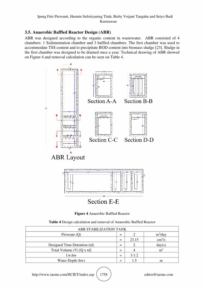
3.5. Anaerobic Baffled Reactor Design (ABR)
ABR was designed according to the organic content in wastewater. ABR consisted of 4
chambers: 1 Sedimentation chamber and 3 baffled chambers. The first chamber was used to
accommodate TSS content and to precipitate BOD content into biomass sludge [23]. Sludge in
the first chamber was designed to be drained once a year. Technical drawing of ABR showed
on Figure 4 and removal calculation can be seen on Table 4.
Figure 4 Anaerobic Baffled Reactor
Table 4 Design calculation and removal of Anaerobic Baffled Reactor
ABR STABILIZATION TANK
Flowrate (Q) = 2 m3/day
= 23.15 cm3/s
Designed Time Detention (td) = 2 day(s)
Total Volume (V) [Q x td] = 4 m3
l:w:hw = 3:1:2
Water Depth (hw) = 1.5 m

Design and Application of Wastewater Treatment Plant for “Pempek” Food Industry,
Surabaya, Indonesia
http://www.iaeme.com/IJCIET/index.asp 1759 [email protected]
Length (l) = 3.3 m
Width (w) = 0.8 m
Surface Area (As) [l x w] = 2.67 m2
Freeboard (fb) = 0.2 m
Depth (h) = 1.7 m
ABR COMPARTMENTS
Organic Loading Rate (OLR) = 3 Kg COD/m3.day
OLR Based Volume (V OLR) = 4.76 m3
Length (l) = 0.8 m
Width (w) = 0.8 m
Water Depth (hw) = 1.5 m
Depth (h) = 1.7 m
Surface Area per Compartment [l x w] = 0.64 m2
Compartment Volume (V Comp) [l x w x hw] = 0.90 m3
Number of Compartment [V OLR / V Comp] = 5
COD [IN] = 10220.00 mg/L
COD Removal = 70 %
COD [OUT] = 3066 mg/L
TSS [IN] = 182.113 mg/L
TSS Removal = 50 %
TSS [OUT] = 91.06 mg/L
3.6. Anaerobic Bio Filter Design (ABF)
ABF was planned to reduce the remaining organic matter from previous unit. ABF was chosen
due to the calculated amount of organic content that still high after ABR treatment [23]. The
effluent of ABF was expected to have COD content under 1000 mg/L to prevent the death of
plant used in Constructed Wetland (CW) [24]. ABF consisted of 3 chambers: 2 filtration
chambers and 1 effluent collector chamber. Filtration chambers in ABF were filled by gravel
and sand as the filter medium for bacterial growth, this option was chosen because of the
abundant availability of this medium at the location. The collector chamber was designed to
collect the effluent from ABF to be pumped into CW. Technical drawing of ABF can be seen
in Figure 5 and removal calculation showed on Table 5.

Ipung Fitri Purwanti, Harmin Sulistiyaning Titah, Bieby Voijant Tangahu and Setyo Budi
Kurniawan
http://www.iaeme.com/IJCIET/index.asp 1760 [email protected]
Figure 5 Anaerobic Bio Filter
Table 5 Design calculation and removal of Anaerobic Bio Filter
Flowrate (Q) = 2 m3/day
= 23.15 cm3/s
Volume of ABF (V) = 3.5 m3
Time Detention (td) [V / Q] = 1.75 day(s)
Water Depth (hw) = 1 m
Length (l) = 2 m
Width (w) = 1.5 m
Surface Area (As) [l x w] = 3 m2
Freeboard (fb) = 0.2 m
Depth (h) = 1.2 m
COD [IN] = 3066.00 mg/L
COD Removal = 70 %
COD [OUT] = 919.8 mg/L
TSS [IN] = 91.06 mg/L
TSS Removal = 70 %
TSS [OUT] = 27.32 mg/L

Design and Application of Wastewater Treatment Plant for “Pempek” Food Industry,
Surabaya, Indonesia
http://www.iaeme.com/IJCIET/index.asp 1761 [email protected]
3.7. Constructed Wetland Design (CW)
CW was used to reduce high nutrient content in wastewater [15]. CW was planned as the last
treatment unit because the limitation of organic content that can be exposed to plant [24]. CW
was planted with Scirpus grossus and Thypa angustifolia [26, 27]. These plant species were
known to have high ability in resisting organic matter and high capability in removing nutrient
content [31, 32, 33]. CW was filled with soil medium and designed to have a sub-surface flow
[33]. Number of S. grossus and T. angustifolia was 1 for every 5 kilograms of medium used
[25]. Total medium used were 100 kilograms, so the number of S. grossus is equal to T.
angustifolia which were 10 plants. The effluent of CW was planned to be directly discharged
to tertiary drainage channel. Technical drawing of CW showed on Figure 6 and calculation of
parameter removal can be seen on Table 6.
Figure 6 Constructed Wetland
3.8. WWTP Start-up
After completely built all unit designed for WWTP, a waterproofing for all unit was conducted
to prevent wastewater leakage to the groundwater. A complete leakage check was carried out
by filling up all unit with tap water and let it over for 1 day, the surface of water level was
marked in every unit for further checking. Surface water level after 1 day of water filling then
checked. If the level is lower than the day marked before, those units would be drained, and re-
waterproofing will be carried out once again [34]. This stage was conducted until all unit were
confirmed to not to be leaked.

Ipung Fitri Purwanti, Harmin Sulistiyaning Titah, Bieby Voijant Tangahu and Setyo Budi
Kurniawan
http://www.iaeme.com/IJCIET/index.asp 1762 [email protected]
Table 6 Design calculation and removal of Constructed Wetland
Flowrate (Q) = 2 m3/day
= 23.15 cm3/s
Volume of CW (V) = 0.75 m3
Time Detention (td) [V / Q] = 0.375 day(s)
Water Depth (hw) = 0.5 m
Length (l) = 3 m
Width (w) = 0.5 m
Surface Area (As) [l x w] = 2 m2
Freeboard (fb) = 0.1 m
Depth (h) = 0.6 m
Number of Plant = 10
COD [IN] = 919.80 mg/L
COD Removal = 90 %
COD [OUT] = 91.98 mg/L
TSS [IN] = 27.32 mg/L
TSS Removal = 70 %
TSS [OUT] = 8.20 mg/L
NH3 [IN] = 454.03 mg/L
NH3 Removal = 90 %
NH3 [OUT] = 45.403 mg/L
WTP start-up was begun by inoculating sedimentation chamber of ABR and first filtration
chamber of ABF with one liter of bacterial inoculum solution (EM16, Indonesia) each. EM16
was used as bacterial seed to degrade organic content in wastewater [23]. After inoculation, an
acclimatization of all unit was carried out by filling and flooding all unit with real wastewater
[34]. Acclimatization was conducted to start the bacterial processes inside all unit until it met
the steady state. Acclimatization was carried out for 3 weeks [34]. After acclimatization stage,
the entire removal process in WWTP can be declared as stable. Complete unit series of WWTP
along with its hydraulic profile showed on Figure 7.
Figure 7 Profile of WWTP
3.9. WWTP Removal
Table 7 showed that all parameter tested were highly decreased compared to initial wastewater
characteristic. This result prove that high organic and nutrient wastewater can be treated using

Design and Application of Wastewater Treatment Plant for “Pempek” Food Industry,
Surabaya, Indonesia
http://www.iaeme.com/IJCIET/index.asp 1763 [email protected]
a combination of physical, biological and phyto-treatment. Complete removal efficiency for
each parameter were shown on Figure 8.
Table 7 Treated wastewater characteristic
Parameter Unit
Initial
Wastewater
Characteristic
Treated
Wastewater
Characteristic
Effluent Standard Method
pH - 4.17 7.55 6-9 pHmeter
TSS mg/L 590 16 30 Gravimetric
BOD mg/L O2 7,996 19 100 Winkler
COD mg/L O2 11,760 34 150 Reflux
NH3-N mg/L 454.03 <5 5 Kjeldahl
Oil and Grease mg/L 794 <2 15 Gravimetric
Figure 8 Removal percentage for each parameter
4. CONCLUSION
Pempek wastewater contains high organic, suspended solid, nutrient, oil and grease content. A
combination of physical, biological and phyto-treatment can be used to treat these kinds of
wastewater. A complete WWTP can reduce COD up to 99.71%, BOD up to 99.76%, Nitrogen
up to 98.90%, Oil and Grease up to 99.75% from initial characteristic of wastewater.
REFERENCES
[1] Karneta, R. Thermal Diffusivity and Shelf Life of Pempek Lenjer. Jurnal Keteknikan
Pertanian, 1(1), 2013, pp. 131-141
[2] Karneta, R. Analisis Kelayakan Ekonomi dan Optimasi Formulasi Pempek Lenjer Skala
Industri. Jurnal Pembangunan Manusia, 4(12), 2010, pp. 1-11
[3] Saifrudin. Pengambilan Protein dari Limbah Ikan Industri Pempek dengan Ekstraksi
Menggunakan Asam Asetat dan Penentuan Komposisi Asam Amino Protein Hasil
[Dissertation]. Indonesia: Universitas Gadjah Mada, 2011
97.29
99.76 99.72
98.9
99.75
97
97.5
98
98.5
99
99.5
100
TSS BOD COD NH3-N Oil and
Grease
Rem
oval
Per
centa
ge
(%)
Parameter

Ipung Fitri Purwanti, Harmin Sulistiyaning Titah, Bieby Voijant Tangahu and Setyo Budi
Kurniawan
http://www.iaeme.com/IJCIET/index.asp 1764 [email protected]
[4] Zainuddin. Industri Pempek Rungkut Punya IPAL. Kadin Surabaya; 2018. Available from:
http://kadinsurabaya.or.id/read/industri-pempek-rungkut-punya-ipal
[5] Suryaningrum, T. D. and Muljanah, I. Prospek Pengembangan Usaha Pengolahan Pempek
Palembang. Squalen, 4(1), 2009, pp. 31-40
[6] Dwijaya, O., Lestari, S. and Hanggita, S. Chemical Characteristics and Potential Heavy
Metal Contamination (Pb and Cd) of Pempek in Palembang. Jurnal Teknologi Hasil
Perikanan, 4(1), 2015, pp. 57-66
[7] East Java Governor. Act No 72, 2013 on Effluent Quality Standard of Fish Processing
Wastewater. Indonesia, 2013
[8] Ogbonna, J. C., Yoshizawa, H., and Tanaka, H. Treatment of High Strength Organic
Wastewater by a Mixed Culture of Photosynthetic Microorganisms. Journal of Applied
Phycology, 12(3), 2000, pp. 277-284
[9] Zheng, C., Zhao, L., Zhou, X., Fu, Z. and Li, An. Chapter 11: Treatment Technologies for
Organic Wastewater. London: Intech, 2013. pp. 249-286
[10] Paing, J., Serdobbel, V., Welschbillig, M., Calvez, M., Gagnon, V., and Chazarenc, F.
Treatment of High Organic Content Wastewater from Food Processing Industry with The
French Vertical Flow Constructed Wetland System. Journal of Water Science Technology,
72(1), 2015, pp. 70-76
[11] Juffrizal, K., Nidzamuddin, M. Y., Tan, C. F., Zulfattah, Z. M., Shaifuddin, M.S.M, and
Aizat, R.A. Design and Efficiency Studies on Skimmers in an Active Grease Trap. Journal
of Engineering and Technology, 5(1), 2014, pp. 121-133
[12] Li, Y., Kang, J., Lau, S., Kayhanian, M., and Stenstrom, M. K. Optimization of Settling
Tank Design to Remove Particles and Metals. Journal of Environmental Engineering,
134(11), 2008, pp. 885-894
[13] Jover-Smet, M., Martín-Pascual, J., and Trapote, A. Model of Suspended Solids Removal
in the Primary Sedimentation Tanks for the Treatment of Urban Wastewater. Water, 9(448),
2017, pp. 1-12
[14] Fuchs, W., Binder, H., Mavrias, G., and Braun, R. Anaerobic Treatment of Wastewater
with High Organic Content Using a Stirred Tank Reactor Coupled with a Membrane
Filtration Unit. Water Research, 37(4), 2013, pp. 902-908
[15] Zhao, F., Yang, W., Zeng, Z., Li, H., Yang, X., He, Z., Gu, B., Rafiq, M. T., and Peng, H.
Nutrient Removal Efficiency and Biomass Production of Different Bioenergy Plants in
Hypereutrophic Water. Biomass and Bioenergy, 42, 2012, pp. 212-218
[16] ReVelle, C. S., and Eiselt, H.A. Location Analysis: A Synthesis and Survey. European
Journal of Operational Research, 165(1), 2005, pp. 1-19
[17] Harvey, David. Chapter 8: Gravimetric Method. Cambridge: Saylor, 1959, pp. 1-55
[18] American Society for Testing and Materials. Standard Test Methods for Chemical Oxygen
Demand (Dichromate Oxygen Demand) of Water. Philadelphia: ASTM Annual Book of
Standards, 1995, pp. 5-14
[19] Delzer, G. C. and McKenzie, S. W. Five-Day Biochemical Oxygen Demand. United States:
USGS, 2003, pp. 1-21
[20] ITW Reagents. Nitrogen Determination by Kjeldahl Method. Spain: PanReac Applichem,
2018, pp. 1-12
[21] OCSD. Design Guidelines for Grease Interceptors. California: Orange County Sanitation
District, 2010, pp. 1-2
[22] Swamee, P. K., and Tyagi, A. Design of Class-I Sedimentation Tanks. Journal of
Environmental Engineering, 1(71), 1996, pp. 71-73
[23] Sasse, L. Decentralized Wastewater Treatment in Developing Countries (DEWATS).
Germany: BORDA, 1998, pp. 1-161

Design and Application of Wastewater Treatment Plant for “Pempek” Food Industry,
Surabaya, Indonesia
http://www.iaeme.com/IJCIET/index.asp 1765 [email protected]
[24] Chernicharo, Carlos Augusto de Lemos. Biological Wastewater Treatment Series. Brazil:
IWA Publishing, 2007, pp. 1-188
[25] USEPA. A Handbook of Constructed Wetlands. United States: USEPA, 1996, pp. 1-53
[26] Jinadasa, K. B., Tanaka, N., Sasikala, S., Werellagama, D. R., Mowjood, M.I., and Ng, W.
J. Impact of Harvesting on Constructed Wetlands Performance – A Comparison Between
Scirpus grossus and Typha angustifolia. Journal of Environmental Science and Health,
43(6), 2008, pp. 664-667
[27] Purwanti, I. F., Simamora D., and Kurniawan, S. B. Toxicity Test of Tempe Industrial
Wastewater on Cyperus rotundus and Scirpus grossus. International Journal of Civil
Engineering and Technology, 9(4), 2018, pp. 1162-1172
[28] Talebizadeh, M., Belia, E., and Vanrolleghem, P. A. Probability-based Design of
Wastewater Treatment Plants. In: International Environmental Modelling and Software
Society (iEMSs) 7th Intl. Congress on Env. Modelling and Software, USA: San Diego
[29] Kurniawan, S. B., Purwanti, I. F., and Titah, H. S. The Effect of pH and Aluminium to
Bacteria Isolated from Aluminium Recycling Industry. Journal of Ecological Engineering,
19(3), 2018, pp. 154-161
[30] Maryland Department of the Environment Engineering and Capital Projects Program.
Design Guidelines for Wastewater Facilities. Washington: Maryland Department, 2016,
pp. 1-20
[31] Ansola, G., Fernández, C., and Luis, E. Removal of Organic Matter and Nutrients from
Urban Wastewater by Using an Experimental Emergent Aquatic Macrophyte System.
Ecological Engineering, 5(1), 1995, pp. 13-19
[32] Al-Baldawi, I. A. W., Abdullah, S. R. S., Suja, F., Anuar, N., and Idris, M.
Phytoremediation of Contaminated Ground Water using Typha angustifolia. Water
Practice and Technology, 10(3), 2015, pp. 616-624
[33] Al-Baldawi, I. A. W., Abdullah, S. R. S., Suja, F., Anuar, N., and Idris, M.
Phytodegradation of Total Petroleum Hydrocarbon (TPH) in Diesel-Contaminated Water
using Scirpus grossus. Ecological Engineering, 74, 2015, pp. 463-473
[34] GBRA. Standards and Design Guidelines for Wastewater Treatment Plants and Lift
Stations. Victoria: Guadalupe-Blanco River Authority, 2018, pp. 1-40


