

TABLE OF CONTENTS
I. INTRODUCTION . . . . . . . . . . . . . . . . . . . . . . . . . . . . . . . . . . . . . . . . . . . . . . . . . . . . . . . . . . . . . . . . . . . 1
I.1. When should a grade-separated structure be considered? . . . . . . . . . . . . . . . . . . . . . . . . . . . . . . 1
I.2. Structure Types . . . . . . . . . . . . . . . . . . . . . . . . . . . . . . . . . . . . . . . . . . . . . . . . . . . . . . . . . . . . . . . 2
I.3. Where should a grade-separated structure be placed? . . . . . . . . . . . . . . . . . . . . . . . . . . . . . . . . . 2
II. DESIGN CRITERIA . . . . . . . . . . . . . . . . . . . . . . . . . . . . . . . . . . . . . . . . . . . . . . . . . . . . . . . . . . . . . . . . . 3
II.1. Structure Height . . . . . . . . . . . . . . . . . . . . . . . . . . . . . . . . . . . . . . . . . . . . . . . . . . . . . . . . . . . . . . 3
II.2. Structure Clearance . . . . . . . . . . . . . . . . . . . . . . . . . . . . . . . . . . . . . . . . . . . . . . . . . . . . . . . . . . . 3
II.3. Structure Width . . . . . . . . . . . . . . . . . . . . . . . . . . . . . . . . . . . . . . . . . . . . . . . . . . . . . . . . . . . . . . . 4
II.4. Box Culvert-Type Underpass Entrance Design . . . . . . . . . . . . . . . . . . . . . . . . . . . . . . . . . . . . . . 5
Wing-Walls . . . . . . . . . . . . . . . . . . . . . . . . . . . . . . . . . . . . . . . . . . . . . . . . . . . . . . . . . . . . . . 5
Entrance Flare . . . . . . . . . . . . . . . . . . . . . . . . . . . . . . . . . . . . . . . . . . . . . . . . . . . . . . . . . . . . 5
II.5 Roadway/Railway Overpass Covering . . . . . . . . . . . . . . . . . . . . . . . . . . . . . . . . . . . . . . . . . . . . 6
II.6. Grade . . . . . . . . . . . . . . . . . . . . . . . . . . . . . . . . . . . . . . . . . . . . . . . . . . . . . . . . . . . . . . . . . . . . . 6
II.7. Cross-Slope . . . . . . . . . . . . . . . . . . . . . . . . . . . . . . . . . . . . . . . . . . . . . . . . . . . . . . . . . . . . . . . . . 6
II.8. Surface Treatment . . . . . . . . . . . . . . . . . . . . . . . . . . . . . . . . . . . . . . . . . . . . . . . . . . . . . . . . . . . . 6
II.9. Entrance/Exit Radii . . . . . . . . . . . . . . . . . . . . . . . . . . . . . . . . . . . . . . . . . . . . . . . . . . . . . . . . . . . 7
II.10 Approach Alignment . . . . . . . . . . . . . . . . . . . . . . . . . . . . . . . . . . . . . . . . . . . . . . . . . . . . . . . . . . 7
II.11. Sight Distance Requirements . . . . . . . . . . . . . . . . . . . . . . . . . . . . . . . . . . . . . . . . . . . . . . . . . . . . 7
Stopping Sight Distance . . . . . . . . . . . . . . . . . . . . . . . . . . . . . . . . . . . . . . . . . . . . . . . . . . . . . 7
Landscape/Obstruction Restrictions . . . . . . . . . . . . . . . . . . . . . . . . . . . . . . . . . . . . . . . . . . . . 7
II.12. Cross Street Accessibility . . . . . . . . . . . . . . . . . . . . . . . . . . . . . . . . . . . . . . . . . . . . . . . . . . . . . . . 8
II.13. Lighting . . . . . . . . . . . . . . . . . . . . . . . . . . . . . . . . . . . . . . . . . . . . . . . . . . . . . . . . . . . . . . . . . . . . 8
Safety and Security . . . . . . . . . . . . . . . . . . . . . . . . . . . . . . . . . . . . . . . . . . . . . . . . . . . . . . . . 8
Nighttime Visibility and Function (Lighting Quality not Quantity) . . . . . . . . . . . . . . . . . . . 9
Light Sources . . . . . . . . . . . . . . . . . . . . . . . . . . . . . . . . . . . . . . . . . . . . . . . . . . . . . . . . . . . . . 9
Environmental Sensitivity . . . . . . . . . . . . . . . . . . . . . . . . . . . . . . . . . . . . . . . . . . . . . . . . . . . 9
Luminaire Selections . . . . . . . . . . . . . . . . . . . . . . . . . . . . . . . . . . . . . . . . . . . . . . . . . . . . . . . 9
II.14. Drainage . . . . . . . . . . . . . . . . . . . . . . . . . . . . . . . . . . . . . . . . . . . . . . . . . . . . . . . . . . . . . . . . . . . . 9
II.15. Structure Design Loadings . . . . . . . . . . . . . . . . . . . . . . . . . . . . . . . . . . . . . . . . . . . . . . . . . . . . . 10
II.16. Protective Barriers . . . . . . . . . . . . . . . . . . . . . . . . . . . . . . . . . . . . . . . . . . . . . . . . . . . . . . . . . . . 10
Location . . . . . . . . . . . . . . . . . . . . . . . . . . . . . . . . . . . . . . . . . . . . . . . . . . . . . . . . . . . . . . . . 10
Barrier Height . . . . . . . . . . . . . . . . . . . . . . . . . . . . . . . . . . . . . . . . . . . . . . . . . . . . . . . . . . . 10
II.17. Handrails . . . . . . . . . . . . . . . . . . . . . . . . . . . . . . . . . . . . . . . . . . . . . . . . . . . . . . . . . . . . . . . . . . 10
Height . . . . . . . . . . . . . . . . . . . . . . . . . . . . . . . . . . . . . . . . . . . . . . . . . . . . . . . . . . . . . . . . . . 11
Design . . . . . . . . . . . . . . . . . . . . . . . . . . . . . . . . . . . . . . . . . . . . . . . . . . . . . . . . . . . . . . . . . 11
II.18. Stairs . . . . . . . . . . . . . . . . . . . . . . . . . . . . . . . . . . . . . . . . . . . . . . . . . . . . . . . . . . . . . . . . . . . . 11
II.19. Elevators . . . . . . . . . . . . . . . . . . . . . . . . . . . . . . . . . . . . . . . . . . . . . . . . . . . . . . . . . . . . . . . . . . . 11
II.20. Signing/Striping . . . . . . . . . . . . . . . . . . . . . . . . . . . . . . . . . . . . . . . . . . . . . . . . . . . . . . . . . . . . . 11
Signing Guidelines . . . . . . . . . . . . . . . . . . . . . . . . . . . . . . . . . . . . . . . . . . . . . . . . . . . . . . . . 11
Striping Guidelines . . . . . . . . . . . . . . . . . . . . . . . . . . . . . . . . . . . . . . . . . . . . . . . . . . . . . . . 11
Way-Finding Signing . . . . . . . . . . . . . . . . . . . . . . . . . . . . . . . . . . . . . . . . . . . . . . . . . . . . . . 11
II.21. Wildlife Movement . . . . . . . . . . . . . . . . . . . . . . . . . . . . . . . . . . . . . . . . . . . . . . . . . . . . . . . . . . . 11
II.22. Bird Nesting Treatments . . . . . . . . . . . . . . . . . . . . . . . . . . . . . . . . . . . . . . . . . . . . . . . . . . . . . . . 11
September 2001 Page I
Design Guidelines forGrade-Separated Pedestrian, Cyclist
and Equestrian Structures�����������������
Felsburg Holt & Ullevig

III. AESTHETIC APPEARANCE . . . . . . . . . . . . . . . . . . . . . . . . . . . . . . . . . . . . . . . . . . . . . . . . . . . . . . . . 12
III.1. Landscaping . . . . . . . . . . . . . . . . . . . . . . . . . . . . . . . . . . . . . . . . . . . . . . . . . . . . . . . . . . . . . . . . 12
III.2. Wall Treatments . . . . . . . . . . . . . . . . . . . . . . . . . . . . . . . . . . . . . . . . . . . . . . . . . . . . . . . . . . . . . 13
Interior. . . . . . . . . . . . . . . . . . . . . . . . . . . . . . . . . . . . . . . . . . . . . . . . . . . . . . . . . . . . . . . . . . 13
Exterior . . . . . . . . . . . . . . . . . . . . . . . . . . . . . . . . . . . . . . . . . . . . . . . . . . . . . . . . . . . . . . . . 13
Color . . . . . . . . . . . . . . . . . . . . . . . . . . . . . . . . . . . . . . . . . . . . . . . . . . . . . . . . . . . . . . . . . . . 13
III.3. Rest Benches . . . . . . . . . . . . . . . . . . . . . . . . . . . . . . . . . . . . . . . . . . . . . . . . . . . . . . . . . . . . . . . 13
III.4. Artwork . . . . . . . . . . . . . . . . . . . . . . . . . . . . . . . . . . . . . . . . . . . . . . . . . . . . . . . . . . . . . . . . . . . 14
III.5. Street Name, Construction Date and Clearance References . . . . . . . . . . . . . . . . . . . . . . . . . . . 14
III.6. Vandalism Deterrents . . . . . . . . . . . . . . . . . . . . . . . . . . . . . . . . . . . . . . . . . . . . . . . . . . . . . . . . . 14
IV. SECURITY . . . . . . . . . . . . . . . . . . . . . . . . . . . . . . . . . . . . . . . . . . . . . . . . . . . . . . . . . . . . . . . . . . . . 14
IV.1. Lighting . . . . . . . . . . . . . . . . . . . . . . . . . . . . . . . . . . . . . . . . . . . . . . . . . . . . . . . . . . . . . . . . . . . 14
IV.2. Emergency Phone . . . . . . . . . . . . . . . . . . . . . . . . . . . . . . . . . . . . . . . . . . . . . . . . . . . . . . . . . . . . 14
IV.3. Vehicle Restriction . . . . . . . . . . . . . . . . . . . . . . . . . . . . . . . . . . . . . . . . . . . . . . . . . . . . . . . . . . . 14
V. CONSTRUCTABILITY ISSUES . . . . . . . . . . . . . . . . . . . . . . . . . . . . . . . . . . . . . . . . . . . . . . . . . . . . . . 15
VI. MAINTENANCE AND OPERATION . . . . . . . . . . . . . . . . . . . . . . . . . . . . . . . . . . . . . . . . . . . . . . . . . . 15
REFERENCES . . . . . . . . . . . . . . . . . . . . . . . . . . . . . . . . . . . . . . . . . . . . . . . . . . . . . . . . . . . . . . . . . . . . 16
GRAPHICS AND TABLES
Roadway/Railway Overpass . . . . . . . . . . . . . . . . . . . . . . . . . . . . . . . . . . . . . . . . . . . . . . . . . . . . . 2
Bridge Over Water Routes . . . . . . . . . . . . . . . . . . . . . . . . . . . . . . . . . . . . . . . . . . . . . . . . . . . . . . 2
Bridge Underpass . . . . . . . . . . . . . . . . . . . . . . . . . . . . . . . . . . . . . . . . . . . . . . . . . . . . . . . . . . . . . 2
Roadway/Railway Underpass . . . . . . . . . . . . . . . . . . . . . . . . . . . . . . . . . . . . . . . . . . . . . . . . . . . . 2
Table 1 . . . . . . . . . . . . . . . . . . . . . . . . . . . . . . . . . . . . . . . . . . . . . . . . . . . . . . . . . . . . . . . . . . . . . 4
Typical Wing-Wall Design . . . . . . . . . . . . . . . . . . . . . . . . . . . . . . . . . . . . . . . . . . . . . . . . . . . . . . 5
Entrance Flare Treatment . . . . . . . . . . . . . . . . . . . . . . . . . . . . . . . . . . . . . . . . . . . . . . . . . . . . . . . 5
Surface Treatment for Equestrian Usage . . . . . . . . . . . . . . . . . . . . . . . . . . . . . . . . . . . . . . . . . . . 6
Table 2 . . . . . . . . . . . . . . . . . . . . . . . . . . . . . . . . . . . . . . . . . . . . . . . . . . . . . . . . . . . . . . . . . . . . . 7
Typical Cross Street Accessibility Design . . . . . . . . . . . . . . . . . . . . . . . . . . . . . . . . . . . . . . . . . . 8
Drainage Pan Design . . . . . . . . . . . . . . . . . . . . . . . . . . . . . . . . . . . . . . . . . . . . . . . . . . . . . . . . . 10
Path Below Water Elevation . . . . . . . . . . . . . . . . . . . . . . . . . . . . . . . . . . . . . . . . . . . . . . . . . . . 10
Surface Treatment for Typical Wildlife Movement . . . . . . . . . . . . . . . . . . . . . . . . . . . . . . . . . . 11
Table 3 . . . . . . . . . . . . . . . . . . . . . . . . . . . . . . . . . . . . . . . . . . . . . . . . . . . . . . . . . . . . . . . . . . . . 13
Typical Structure Reference Information . . . . . . . . . . . . . . . . . . . . . . . . . . . . . . . . . . . . . . . . . . 14
Emergency Phone Mounting . . . . . . . . . . . . . . . . . . . . . . . . . . . . . . . . . . . . . . . . . . . . . . . . . . . 14
REPRESENTATIONAL SKETCHES OF GUIDELINE INTENT . . . . . . . . . . . . . . . . . . . . . . . . . . . . . . . . . . 17
PHOTO EXAMPLES OF GUIDELINE INTENT . . . . . . . . . . . . . . . . . . . . . . . . . . . . . . . . . . . . . . . . . . . . 22-26
September 2001 Page II
Design Guidelines forGrade-Separated Pedestrian, Cyclist
and Equestrian Structures�����������������
Felsburg Holt & Ullevig

I. INTRODUCTION
The City of Fort Collins is committed to designing and
building our community transportation facilities to
accommodate all modes of travel as well as to
encourage the use of alternative modes such as walking
and bicycling.
The objective of this Design Guidelines for Grade-Separated Pedestrian, Cyclist and EquestrianStructures manual is to establish design principles for
grade-separated crossings in order to foster a more
complete transportation network throughout the Fort
Collins community.
Grade-separated crossings can help - if designed
properly - to reduce conflicts among vehicles, cyclists
and pedestrians along our City’s roadways which often
serve the community’s highest concentrations of
commercial, retail, and employment corridors. The
high speed and/or volume of motor vehicle traffic
creates safety hazards for cyclists and pedestrians who
are trying to cross these roadways in order to travel to
their employment destinations, residential areas,
schools, adjacent transit stops, or near-by retail centers.
Particularly as Fort Collins grows in population and
travel demand, these types of grade-separated crossings
will become more and more critical to balancing the
needs of maximizing roadway operations with the need
to provide convenient pedestrian/bicycle connectivity
throughout a multimodal transportation system.
In addition to including design guidelines for grade-
separated facilities either over or under roadways, this
manual also addresses crossings of waterways,
railroads, and other potential barriers and includes
design considerations for equestrians as well as for
cyclists and pedestrians.
This manual is not intended to prescribe where and
when grade separated crossings must be provided.
Instead, it provides a user-friendly format for
evaluating design considerations and solutions when a
grade-separated crossing is determined to be
appropriate in terms of overall system design. It does
offer suggestions in terms of conditions that may lead
to the decision to incorporate a grade-separated
crossing as part of the transportation system. Other
resources such as the Larimer County Urban AreaStreet Standards and other national publications should
also be consulted in determining the final design of a
specific project.
I.1. When should a grade-separatedstructure be considered?
The construction of a grade-separated facility is not an
endeavor to be taken lightly. When designed and
constructed properly a grade-separated structure can
become an attractive safety feature that can be used by
all of a community’s residents. Considering the effort
and cost to design and construct such a structure,
proper planning is essential to its success.
The City of Fort Collins does not consider the number
of users as a factor in determining whether or not to
build a grade-separated structure. Its philosophy,
rather, is to provide an attractive and continuous
transportation and recreational system for all levels of
daily use.
The following four situations are a sample of when a
grade-separated structure should be considered:
1. Where pedestrian-oriented uses such as shopping
centers, schools, recreational facilities or other
activity centers are separated from pedestrian
generators such as neighborhoods or employment
centers by high-volume and/or high-speed streets.
2. Along designated bike/pedestrian trails or corridors
that cross high-volume and/or high- speed streets
where a grade-separated structure provides the best
opportunity for system continuity and safety for all
levels of pedestrian volume.
3. Along designated trails or corridors where a
physical obstacle such as a railway or a river,
stream or other drainage-way exists.
4. Where a structure would compliment a mass transit
facility or is necessary to access a mass transit
system.
5. Where a structure would improve cross-street
traffic flow by eliminating at-grade
pedestrian/cyclist crossings.
Design Guidelines forGrade-Separated Pedestrian, Cyclist
and Equestrian Structures
September 2001 Page 1
�����������������
Felsburg Holt & Ullevig

I.2. Structure TypesThese guidelines concentrate on four fundamental
types of grade-separated structures shown graphically
on this page. They include:
1. An overpass over a roadway or railway; includes
both elevated (when the roadway or railroad is at-
grade) and at-grade structures (when the roadway
or railroad is depressed below the natural ground
surface).
2. A bridge over water routes such as rivers, streams,
drainage-ways, typically with little or no elevation
difference between the structure and natural
ground.
3. A bridge underpass, typically adjacent a river,
stream or other drainage-way.
4. An underpass under a roadway or railway by
means of a box culvert.
The type of structure to be used at any given location
shall be discussed with City of Fort Collins staff before
the design of such a structure begins.
I.3. Where should a grade-separatedstructure be placed?
The physical location of a grade-separated structure is
also important. An improperly placed structure may
not achieve its full usage. The location of grade-
separated structures should consider the following
factors when determining the exact placement of a
structure:
1. Provide system continuity along the normal path of
pedestrian, cyclist and equestrian movements.
2. Located to minimize out-of-direction travel.
3. Where any extra effort or time required to use the
facility would not hinder its use.
4. Logical geographical sites such as fill or cut areas
along roadways, railways or waterways.
5. Where it would minimize the impact to cross-street
traffic.
September 2001 Page 2
Design Guidelines forGrade-Separated Pedestrian, Cyclist
and Equestrian Structures�����������������
Felsburg Holt & Ullevig
1. Roadway/Railway Overpass
2. Bridge Over Water Routes
3. Bridge Underpass4. Roadway/Railway Underpass
���
���
���

II. DESIGN CRITERIA
The design characteristics of a grade-separated
structure must take into account numerous factors such
as the type of obstacle that is being crossed, the
surrounding land topography, the location of nearby
drainage features, the length of the structure, visual
impact, and maintenance and constructability to name
a few. The following information serves as a guide to
providing not only a safe and attractive facility, but
also to strive for a level of structure consistency
throughout the City.
II.1. Structure HeightIt is critical to assure that the height of a grade-
separated structure adequately meets specified
dimensions for clearance so that pedestrians, cyclists,
equestrians, and maintenance or emergency vehicles
can safely use the facility. Dimensions are measured
from the walking surface to the overhead obstruction.
Overpass or underpass used by pedestrians andcyclists—10 feet desirable, 8 feet minimum.
Overpass or underpass also used by equestrians—
12 feet desirable, 10 feet minimum.
Overpass or underpass also used by emergencyvehicles—13’-6”. This dimension is required for
structures where vehicle access cannot be provided to
both sides of the structure from a cross street, trail or
other access facility due to physical or topographical
constraints. Project-specific design must be
coordinated with the Poudre Fire Authority.
II.2. Structure ClearanceFor overpasses that cross over a roadway or railway,
the following clearance distances shall be provided
along the entire length of the structure between the
bottom of the structure and the roadway or railway
surface:
Clearance between bottom or low chord of pedestrianstructure and roadway—17’-6” minimum on state
highways. On other city roadways, consult the
Larimer County Urban Area Street Standards.
Clearance between bottom or low chord of pedestrianstructure and railway tracks—23’-6” minimum.
For bridges over water routes, adequate clearance
should be provided between the bottom of the structure
and the normal water level to minimize the impact of
minor flood occurrences. Bridges must be constructed
out of the 100-year floodplain, or breakaway bridges
and railings must be constructed in accordance with the
City’s Stormwater Utility regulations.
For a box culvert-type underpass, the minimum cover
from the roadway pavement surface to the top of the
box culvert shall be structurally verified to assure that
vehicle loadings on the top of the underpass do not
diminish the structural integrity of the underpass.
Design Guidelines forGrade-Separated Pedestrian, Cyclist
and Equestrian Structures
September 2001 Page 3
�����������������
Felsburg Holt & Ullevig

II.3. Structure WidthThe width of a structure is as important as the structure
height. A structure that is too narrow can be perceived
as unsafe or simply not an inviting or pleasing facility
that residents would want to use. The minimum
dimensions identified below must be provided between
any obstructions such as handrails, lighting, barriers,
drainage facilities or artwork.
1. Entering path/trail/sidewalk width (minimum of
10 feet) plus 2 feet clear obstruction and drainage
distance on each side; total of 14 feet.
2. For underpasses greater than 80 feet in length,
refer to Table 1 for the minimum structure width.
3. For structures that include drainage facilities,
(other than drainage pans as shown in
Section II.14), the width of the drainage facility
shall be in addition to the width dimensions noted
in Table 1.
4. For structures that will accommodate equestrian
usage, the width of the equestrian path, typically
6 feet, shall be in addition to the width dimensions
noted in Table 1.
5. For structures over roadways or railways, the
desirable structure width shall be 12 feet with a
minimum width of 10 feet.
6. For structures that will accommodate emergency
vehicles, the minimum width will typically be
20 feet. The Poudre Fire Authority shall be
consulted on a project by project basis to
determine structure width and surface material
requirements when emergency access is necessary.
7. For structures that will accommodate wildlife
movements, the width for wildlife movements shall
be in addition to the width dimensions noted in
Table 1. A biologist shall be consulted to identify
expected wildlife types and determine additional
structure width.
Design Guidelines forGrade-Separated Pedestrian, Cyclist
and Equestrian Structures
September 2001 Page 4
�����������������
Felsburg Holt & Ullevig
Structure Length Minimum Structure Width Comments
TTaabbllee 11MMiinniimmuumm UUnnddeerrppaassss SSttrruuccttuurree WWiiddtthh
<80 feet
80 feet to <110 feet
110 feet to <150 feet
150 feet to <200 feet
>200 feet
14 feet
16 feet
18 feet
20 feet
22 feet
For structures >150 feet in length, and where
there is a median of sufficient width, two
separate structures should be used to provide
an opening of natural light. If two separate
structures cannot be provided, skylights placed
in a median, if available, shall be required.
Includes 2 feet on each side of the structure for
drainage pans and/or amenity (such as
handrails, rubrails) clearance. For structures
of 80 feet or greater in length, skylights shall
be provided in the roadway median if a
median is available.

II.4. Box Culvert-TypeUnderpass Entrance Design
The design of the entrance to a box culvert-
type underpass is critical to the user
comfort level of the facility. How the wing-
walls are constructed to visually minimize
the “tunnel” effect can be the difference
between a well-used and avoided facility.
Following are a few guidelines for entrance
treatments.
WWiinngg--WWaallllssThe intent of wing-walls is to retain the
adjacent fill or natural ground. The typical
design approach may not be the only
acceptable design, however. The designer
should consult with City staff regarding the
proposed design at the initial stage of
design preparation.
1. Wing-walls shall typically be
constructed at a 45 degree angle
measured from the face of the structure.
2. Wing-walls shall extend six inches
above the adjacent ground slope.
3. The length of the wing-wall is
dependent upon the height of the
structure and the adjacent ground slope.
4. The roadway fill slope behind the wing-
wall typically shall be 4:1.
5. Construct wing-wall faces to be inviting to users.
EEnnttrraannccee FFllaarreeFor structures of 80 feet or greater in length, the first
ten feet at both ends of the structure shall be flared an
additional 2 feet on each side of the structure to reduce
the effect of “tunneling” by inducing deeper daylight
penetration.
Entrance Flare Treatment
��������
�� ������������ � ������������������ ��
������������
� ��
��
�����
�����
�� ����������
��������� ���
!"
#���� ��������
#
$�%�&������'$'
()�&���*� ��������'$'�+�,("������� ���
Design Guidelines forGrade-Separated Pedestrian, Cyclist
and Equestrian Structures
September 2001 Page 5
�����������������
Felsburg Holt & Ullevig
� &��-���,)
() !)
.()
.�)�()
*���/����������+�0����
��������
�� ������������ � ������������������ ��
������������
� ��
��
�����
�����
&
�� ����������
#��������� ���
�
�
�1!�2�3'
�- %�
4� �� ��!)5('
�
�����������������������
#���� ��������
Typical Wing-Wall Design

II.5 Roadway/Railway OverpassCovering
Overpasses that cross roadways, railways, or major
drainage-ways should be covered to limit snow, ice, or
water buildup on the walking surface. The covering
shall be of a solid material and be integral to the
structural components of the overpass design. In
addition to protection from weather elements, a
covering can also provide a location for the attachment
of lighting facilities to create a more attractive
environment and enhance safety.
II.6. GradeThe longitudinal grade of any structure, or any ramp or
path accessing a structure, shall be 5% (20:1 ratio) or
less. If physical constraints restrict achieving a 5%
grade, a maximum of 8.33% (12:1 ratio) is permitted;
however, grades greater than 5% require landings in
the structure as follows:
� >5.00% (20:1 ratio) to 6.25% (16:1 ratio) =landing every 40 feet
� >6.25% (16:1 ratio) to 8.33% (12:1 ratio) =landing every 30 feet
The size of a landing shall be 5 feet long for the entire
width of the ramp/path. If there is a change of
direction in the ramp/path at a landing location, the
minimum landing dimension shall be 5 feet by 5 feet1.
II.7. Cross-SlopeThe design of cross-slopes for any structure shall be
the responsibility of the structure engineer with the
objective being to reduce flat areas where water or
debris could accumulate. The typical cross-slope for
entrance/exit paths shall be 2%. The minimum cross-
slope in a box culvert-type underpass shall be 1%.
II.8. Surface TreatmentThese guidelines do not strictly specify the type of
material to be used for the construction of grade-
separated crossings; however, since a design life of
50 years for overpasses and bridges, and 100 years for
underpasses2 must be provided, it is likely that a
concrete surface will be the most common choice. A
wooden walking surface is discouraged given its
relatively shorter life span and greater ease of
destruction and/or vandalism. It is imperative that the
pavement surface be smooth and devoid of
irregularities that could affect the comfort and safety of
pedestrians and cyclists. In underpasses where there is
a likelihood of flooding, the surface shall be concrete
and provided with a texture to resist slipping.
For facilities that accommodate pedestrians, cyclists
and equestrians, a separate riding/walking surface for
equestrians is necessary. For these structures,
aggregate base material shall be used for the equestrian
surface. The structure shall be designed so that this
material remains within the structure boundaries and
does not wash away or extend along the walking and
riding surface for pedestrians and cyclists. If possible,
a rider dismount area should be provided near structure
entrances.
Surface Treatment for Equestrian Usage
����+��� ��1�6�7��+�� ���#�����8 ���+
9��+��� �� ���#����������3"
3'�6��7��������+��� ��1$�7�7���� ��
!"�:����� ��$ +��- ���� �
Design Guidelines forGrade-Separated Pedestrian, Cyclist
and Equestrian Structures
September 2001 Page 6
�����������������
Felsburg Holt & Ullevig

II.9. Entrance/Exit RadiiAt structure locations where the entrance/exit to a
facility will require a curved path or ramp, the radius
information of Table 2 shall apply.
When curve radii smaller than those shown in Table 2
must be used due to limited right-of-way,
topographical features or other considerations, standard
curve warning signs and supplemental pavement
markings shall be installed in accordance with the
Manual On Uniform Traffic Control Devices(MUTCD).3 Other accommodations shall be made to
facilitate safe movements. One method would be to
widen the trail at sharp curves.
II.10 Approach AlignmentApproaches to each structure type shall have a
minimum of 20 feet of straight trail alignment before
accessing the structure.
II.11. Sight Distance Requirements
SSttooppppiinngg SSiigghhtt DDiissttaanncceeThe minimum stopping sight distance necessary to
provide adequate reaction time to avoid unforeseen
circumstances shall be per AASHTO4 requirements.
These data provide the minimum stopping sight
distance for a cyclist to come to a full controlled stop
for varying design speeds and grades.
LLaannddssccaappee//OObbssttrruuccttiioonn RReessttrriiccttiioonnssLandscaping and/or other obstructions that could
restrict user visibility will not be permitted. Low-type
ground covers are encouraged within user sight lines.
Design Guidelines forGrade-Separated Pedestrian, Cyclist
and Equestrian Structures
September 2001 Page 7
�����������������
Felsburg Holt & Ullevig
TTaabbllee 22MMiinniimmuumm CCeenntteerrlliinnee EEnnttrraannccee//EExxiitt RRaaddiiii
15° Cyclist Lean Angle2% Superelevation Rate and
20° Cyclist Lean Angle
30
90
155
260
0.31
0.28
0.25
0.21
12
20
20
30
36
100
150
225
12
20
25
30
Design Speed (mph) Minimum Radius(feet)
Design Speed (mph) FrictionFactor
Minimum Radius(feet)
Source: guide for the development of bicycle facilities, AASHTO, 1999.
II.12. Cross Street AccessibilityAt all structure locations, a path must be provided on
each side of the intersection of the roadway and the
structure for accessibility between the roadway and the
structure. These paths must meet the grade criteria
established in Section II.6. The intent of these
connections is to provide direct and convenient access
to/from the cross street. Informal walking paths/steps
should be provided to serve cut-through pedestrian
traffic in landscape or grass areas.
II.13. LightingLighting provides a welcome dusk and nighttime
atmosphere where structure entrances/exits, destination
points and features are highlighted. Traveled pathways
can also be lighted to provide guidance. The basic
objectives of lighting include:
� Safety and security
� Aesthetic image
� Nighttime visibility and function
� Environmental sensitivity
SSaaffeettyy aanndd SSeeccuurriittyySafety involves providing light on hazards so that they
can be detected with sufficient reaction time. The
lighting system, along with other site design elements,
must provide visual information to assist users in
avoiding collisions or a loss of bearings.
Security is often referred to as the perception of safety.
Providing for security involves lighting potentially
hazardous locations and situations. Lighting can also
act as a crime deterrent by increasing the visibility in
an area of concern.
Design Guidelines forGrade-Separated Pedestrian, Cyclist
and Equestrian Structures
September 2001 Page 8
�����������������
Felsburg Holt & Ullevig
6��++�������6����7����
6��++�������6����7����
- ���� �� - ���� ��
;(��<����+�7����;(��<����+�7����
!()!()
0�����6����7����� +���7�++ ��
0�����6����7����� +���7�++ ��
Typical Cross Street Accessibility Design

NNiigghhttttiimmee VViissiibbiilliittyy aanndd FFuunnccttiioonn ((LLiigghhttiinnggQQuuaalliittyy nnoott QQuuaannttiittyy))Too often, lighting quantity or lighting levels are used
for design instead of lighting quality. Lighting quality
involves contrast, brightness adaptation, glare and light
source color. Increasing contrast will increase
visibility. An example of poor contrast would be a
person in dark clothing against a dark wall. If the wall
is lighted, objects are easier to see.
Eyes adjust to the brightest object in the field of view.
This adjustment is referred to as brightness adaptation.
If an object is very bright, like uncontrolled light from
a floodlight, everything else in the immediate
surrounding area appears relatively dark, making it
harder to detect object details.
Glare is usually caused by uncontrolled light emitted
from unshielded luminaires. An example of this is
unshielded wall pack fixtures or floodlights located on
a wall. These situations can be easily avoided with
proper equipment selection, location, aiming and
shielding. Light sources and luminaries on overpasses
shall not be so bright that the brightness causes a
hazard to motorists driving below.
LLiigghhtt SSoouurrcceessLight source color is another key to low light level
visibility. Night vision is very sensitive to short
wavelength light (blue and green light), resulting in
crisp and clear vision, especially in peripheral vision.
Reaction time and color recognition under low light
levels is far superior with white light sources like metal
halide, fluorescent, and induction lamps.
EEnnvviirroonnmmeennttaall SSeennssiittiivviittyyEnvironmental sensitivity includes minimizing light
trespass and lighting pollution, and using minimal
energy through lighting equipment selection and
operation. Recommended practice “Lighting for
Exterior Environments”5 shall be used as criteria to
limit light pollution and light trespass.
Light trespass is sometimes referred to as the “light
shining in my window” syndrome. Usual culprits are
unshielded floodlights, high wattage pedestrian lights,
wall packs and other unshielded luminaires that are
improperly located and poorly aimed. Light trespass
can be minimized with careful equipment selection,
proper location, and proper aiming and shielding.
Light trespass shall be minimized to the extent
possible.
Light pollution is uncontrolled light that travels into
the atmosphere. This light is wasted energy and
creates a “sky glow”. Unshielded luminaires and
excessively high lighting levels cause light pollution.
High wattage luminaires with poor visual shielding
will not be permitted. Excessive light levels with high
amounts of reflected light will not be permitted. Use
low wattage, shielded luminaires that are properly
located and aimed.
LLuummiinnaaiirree SSeelleeccttiioonnssUnderpass and overpass lighting should enhance the
design theme of the structures. Luminaire selections
should not only be based on photometric performance,
but also on the aesthetic character appropriate for the
design. All luminaires shall be vandal resistant, UL
listed for wet locations, and meet Americans with
Disabilities Act (ADA)1 requirements. The type, style,
color and location of luminaires shall be consulted with
the City of Fort Collins for approval.
II.14. DrainageDrainage facilities should be placed along the edges of
the trail/path and out of the way of the main
pedestrian/cyclist usable surface. Any drainage facility
that must be in or along the usable surface must have a
smooth, flat surface (in the case of a manhole) or inlet
grates that are transverse to the trail/path direction.
Careful consideration should be given to intercept
groundwater at underpass entrances to prevent trail
surface water from entering the structure and freezing
during cold weather.
Each box culvert-type underpass shall be provided with
drainage pans longitudinally along the entire length of
the structure. The drainage pans shall be constructed
of colored concrete to differentiate between the
Design Guidelines forGrade-Separated Pedestrian, Cyclist
and Equestrian Structures
September 2001 Page 9
�����������������
Felsburg Holt & Ullevig

drainage facility and the main travel path. The
drainage pans shall also be provided with a transverse
groove every 2 feet along the structure length to
provide warning to errant cyclists similar to the design
of a rumble-strip along a highway.
Drainage Pan Design
In some cases, the trail system may need to be lower
than an adjacent creek, river or drainageway. The
design of such facilities must be able to restrict normal
water flow from encroaching onto the trail system.
Path Below Water Elevation
II.15. Structure Design LoadingsTypically, overpass structures shall be designed to
accommodate a live load of 85 pounds per square foot.
The design for each structure should be checked,
however, to assure that an 85 pound per square foot
live load is adequate for emergency or maintenance
vehicle loadings.
For other design loadings for overpass and underpass
structures, the engineer should refer to the following:
� “Guide Specifications for Design of Pedestrian
Bridges”6
� “Larimer County Urban Area Street Standards”2
� “AASHTO Specifications for Highway Bridges”7
� “Colorado Department of Transportation Bridge
Design Manual”8
II.16. Protective BarriersLLooccaattiioonnRailing, walls or other types of barriers shall be placed
at locations where pedestrians, cyclists or equestrians
require protection from obstacles; locations such as:
� Along the wing-walls and top of a box culvert typeunderpass,
� On underpasses between the walking surface andadjacent drainage facilities or other water features,
and/or
� On overpasses to reduce the potential for objectsfalling from the overpass onto vehicles, trains or
other users on the roadway, sidewalk or railway
surface below the structure.
These barriers must be designed with care to ensure
aesthetic compatibility with the surrounding area and
to minimize visual impact.
BBaarrrriieerr HHeeiigghhttA 54 inch barrier height shall be provided along the
entire length of the obstacle with a bicycle rub rail
attached at a height of 42 inches.
II.17. HandrailsHandrails to assist in public access along structures
shall be provided when the structure, entering trail
facility or cross-street accessibility path, has a
longitudinal grade greater than 5 percent. Handrails
are required only along one side of the structure,
entering trail facility or cross-street accessibility path.
�� �+=��+��/���=�=����!�*���
!) !)
Design Guidelines forGrade-Separated Pedestrian, Cyclist
and Equestrian Structures
September 2001 Page 10
�����������������
Felsburg Holt & Ullevig
HHeeiigghhttThe height of handrails shall be 34-38 inches above the
structure, trail or path walking surface.
DDeessiiggnnThe design of handrails and their installation shall meet
ADA requirements as documented in Figure 39, Sizeand Spacing of Handrails and Grab Bars, Section 4.26of the Code of Federal Regulations, 28 CFR Part 36,Nondiscrimination on the Basis of Disability by PublicAccommodations and in Commercial Facilities by the
Department of Justice.
II.18. StairsStairs for structure accessibility are discouraged. It is
recognized, however, that certain locations with
physical or topographical constraints may limit the
construction of accessible routes to a grade-separated
structure with appropriate grades as documented in
Section II.6. Stairs may be provided only if an
adequate and reasonable access per ADA requirements
to both sides of the overpass or underpass structure can
be provided.
II.19. ElevatorsThe need for an elevator at a grade-separated structure
shall be decided on a project-by-project basis.
Typically, elevators should not be designed for a
facility if adequate grades can be provided for ramp
construction. If the physical constraints of a structure
location necessitates that the grade criteria of
Section II.6 cannot be met, an elevator shall be
provided.
II.20. Signing/StripingSSiiggnniinngg GGuuiiddeelliinneessThe installation of any warning, regulatory or other
types of signs at structure locations or on structure
approaches shall be per the MUTCD.
SSttrriippiinngg GGuuiiddeelliinneessEach approach to each structure shall have a painted
yellow centerline for approximately 100 feet in
advance of the structure entrance. All curves with
restricted sight distances are required to be painted
with a yellow centerline to separate traffic. The
centerline shall be 4 inches in width.
WWaayy--FFiinnddiinngg SSiiggnniinnggAt junctions of main trails and cross-street access
routes, signing shall be placed to direct users to the
appropriate side of the cross-street for the direction in
which they wish to proceed.
II.21. Wildlife MovementIf an underpass is constructed where there is a
likelihood that the underpass could also serve as a
wildlife movement corridor, the designer should
consult with a biologist to understand what species
may use the underpass, in addition to humans, that
could influence the structure design. Such factors as
the openness of the structure, the presence of a natural
or dirt floor, vegetation within the structure, wall color,
and the absence of artificial lighting must be evaluated
as part of the structure design. An artificial vegetation
barrier could be used where natural light is not
sufficient to grow living vegetation.
Surface Treatment for Typical Wildlife Movement
II.22. Bird Nesting TreatmentsStructures shall be designed so that birds do not nest in
these facilities. A typical treatment for an underpass
would be to have angled top corners at 45 degrees.
����+��� ��1�6�7��+�� ���#�����8 ���+
#�������� ���#����������3"
3'�6��7����� ��
)�:����� ��$ +��- ���� �
8���� �����$ �����#�����:������� ��
Design Guidelines forGrade-Separated Pedestrian, Cyclist
and Equestrian Structures
September 2001 Page 11
�����������������
Felsburg Holt & Ullevig

III. AESTHETIC APPEARANCE
The aesthetic qualities of a grade-separated structure
are as important as the specific design criteria. For
example, a structure may be constructed to the exact
criteria set forth in Section II; however, if the structure
is not attractive, its use will be diminished. Therefore,
the provision for landscaping, wall treatments, artwork
and other features will be given equal consideration
during the design process as would structure width and
height, grade or sight distance.
Much of the success of these types of trail connections
has to do with the perceptions of the trail users. Some
of these perceptions, as in the case of narrow
underpasses, can be safety related. These guidelines
are intended to create a more positive response from all
trail users. Perhaps less critical, but none-the-less
important, is if these structures are perceived as
foreboding features or, in a more positive light, a sort
of gateway to new neighborhoods. If attention is paid
to a number of aesthetic details, these perceptions can
be positive and contribute to the overall success and
connectivity of the surrounding communities.
All of the overpass and underpass features can be
described as being nodes of activity for the
surrounding communities. They are cross roads where
connections to other trail networks and neighborhoods/
activity centers are made. These structures are public
in nature and are worthy of some of the planning and
refinement that are provided for the community’s parks
and streetscapes. Some aesthetic considerations may
include:
� Structures like bridge girders, abutments,wingwalls, and retaining walls must have texture
and color treatments. There may be a corridor
theme of materials that is appropriate. Coarse wall
textures may also help deter graffiti potential. The
use of native materials like stone may also be
appropriate for retaining walls and stream channel
improvements.
� Look for “park” opportunities near these areas.While most commuter trail users have more
practical considerations, recreation trail users
welcome the opportunity to stop for a break and
take in a view of a stream or landscape.
Intersections near bridges and underpasses are
often good locations for this type of activity.
Additional width of trail, a pull-off area, benches,
or shade from a tree, are some features worth
considering.
� Tree and shrub planting, and associated landscapeelements, particularly if in an urban park area, are
important aesthetic considerations.
III.1. LandscapingWhile some trails are utilitarian in nature and confined
to available right-of-way space, many pass through
community open-space corridors. Whether they are
protected open-space natural areas or city parks, both
deserve a collaborative effort of civil engineering and
landscape architecture disciplines for the best results.
Park planning begins with carefully planned and
designed “hard” features like structures, drainageways
and paved trails which are designed to best compliment
the park or open space resources.
The next step becomes to give the trail side “soft” area,
or landscape area, the appropriate refinement. This
may include careful grading of cut and fill slopes so
that they are both attractive and easy to maintain, and
the planting of trees, shrubs and appropriate grasses.
In an urban area this may include irrigation systems
and extensive vegetation or reestablishment of stream
channel habitat. In the dryer Colorado climate, new
tree and shrub plantings require supplemental irrigation
water which is often not available in remote natural
areas. For these reasons, tree and shrub plantings in
these areas is more difficult unless it is a wetland in
nature and depends on natural pre-existing soil
moisture conditions. The choice of landscape
materials shall utilize Xeriscaping techniques and
native plantings that have low water demands.
All new tree and shrub plantings should be located
with ample clearance from the paved trail surface.
Tree clearance over trail surfaces or within sight lines
Design Guidelines forGrade-Separated Pedestrian, Cyclist
and Equestrian Structures
September 2001 Page 12
�����������������
Felsburg Holt & Ullevig

is a safety issue much like street trees in an urban
sidewalk situation. Likewise, materials associated with
a landscape such as boulders and cobble or wood
fences should not be placed in such a way to present
any visual or physical obstruction to trail traffic or
sight lines. Landscape irrigation, if utilized, should
avoid spraying onto the trail surface.
Landscaping shall be provided along structure
approaches. The designer shall take creative license to
develop plans that are both functional and beautiful.
Low, groundcover-type vegetation that helps prevent
slope erosion as well as shrubs to discourage “short-
cutting” is encouraged. The only restrictions are:
1. Landscaping materials shall not interfere with the
minimum sight distance requirements of the
structure.
2. Landscaping design and/or materials shall include
precautions to prohibit small rocks, bark or other
materials from progressing onto the traveled
pathway or into the structure.
3. Landscaping shall not encroach upon the trail that
may constrain circulation such as tree branch
height or vegetation overhang.
The designer of a structure shall employ the services of
a registered landscape architect to develop landscape
plans for the project.
III.2. Wall TreatmentsIInntteerriioorrInterior concrete walls of underpasses shall be
provided with a light colored matte finish to promote a
light reflectivity of 60% or greater. The finish can be a
combination of paint coating, concrete stain or texture
coating. The preferred finish is a paint coating or
concrete stain since these finishes can also be applied
with a graffiti-resistant coating.
EExxtteerriioorr1. Exterior walls along underpass entrances or along
overpass abutments shall be lined with an
aesthetically pleasing treatment such as rock or
trailing vegetation.
2. Exterior steel surfaces on overpasses shall be
finished with a combination primer/urethane or
primer/acrylic coating. A graffiti-resistant coating
shall be applied to all exterior concrete and steel
surfaces.
CCoolloorrAll painted or stained concrete or steel surfaces shall
be finished in light, natural neutral tones. Some of the
accepted federal color standards are shown in Table 3.
The designer shall consult with the City’s Project
Manager to finalize color selection(s) and additional
options for accent colors.
III.3. Rest BenchesEach entry/exit area of an overpass or underpass shall
be equipped with a rest bench or seating area. The
bench shall be incorporated into the
landscaping/streetscape amenities to the extent
possible. The rest benches shall be located away from
the structure entrances and exits and be located in such
a manner that they do not encourage stopping in the
Design Guidelines forGrade-Separated Pedestrian, Cyclist
and Equestrian Structures
September 2001 Page 13
�����������������
Felsburg Holt & Ullevig
TTaabbllee 33AAcccceeppttaabbllee FFiinniisshh CCoolloorrss
FederalColor No.
FederalTable No.
II
II
III
III
IV
IV
VII
VIII
VIII
VIII
VIII
VIII
VIII
VIII
31643
31667
32630
32648
33613
33690
36628
37722
37769
37778
37855
37875
37886
37925

middle of the structure approach and at, or near, path
intersections.
III.4. ArtworkArtwork shall be an integral part of any structure and
reflect the character of the surrounding area. Refer to
Photo Examples of Guideline Intent section of this
report found on pages 22-26.
III.5. Street Name, Construction Date andClearance References
All overpasses and underpasses shall have the cross-
street name, construction date and smallest structure
clearance height inscribed into the overhead portion of
the structure. This information must be a physical part
of the structure, not by a painting or embossing
method. The shortest structure clearance shall be
placed at the point of shortest clearance. The minimum
letter height shall be 6”. Lettering font and materials
can be determined on a project by project basis.
Typical Structure Reference Information
III.6. Vandalism DeterrentsEach overpass and underpass structure shall be
designed to reduce the potential for vandalism to the
extent possible. Such strategies may include:
� Limiting the number of structure materials thatcould be removed
� Install vandal-resistant luminaries
� Hanging/clinging vegetation
In each case, all exposed concrete and steel surfaces
shall be provided with an anti-graffiti coating.
IV. SECURITY
IV.1. LightingInterior and exterior lighting shall be designed per the
guidelines of Section II.13. Lighting shall be designed
to create a pleasant environment while also providing
sufficient security so that the facility continues to be
used at night.
IV.2. Emergency PhoneAn emergency phone shall be placed at one end of
each structure (excluding trail bridges over water
routes). The phone shall have a direct connection to
the local 911 operator for reporting of emergencies.
The top mounting height of the highest mechanical part
of the phone shall be mounting a maximum of 54
inches from the ground surface1.
Emergency Phone Mounting
IV.3. Vehicle RestrictionOverpasses and underpasses shall be designed so that
maintenance or emergency vehicle can reach either
entrance of the structure. Barriers, bollards or other
types of restrictive devices that could cause a hazard
for pedestrians, cyclists or equestrians, or be a barrier
to emergency access shall not be placed at or near
structure entrances.
��'�- %����
������7������
����������
���������� ������
Design Guidelines forGrade-Separated Pedestrian, Cyclist
and Equestrian Structures
September 2001 Page 14
�����������������
Felsburg Holt & Ullevig

V. CONSTRUCTABILITY ISSUES
The construction of an overpass or underpass must
always be conducted in a safe manner and with a
minimal disruption of existing vehicle, train, bike and
pedestrian traffic. Traffic control plans must be
submitted to the City of Fort Collins before permitting
to assure the City that accessibility of all users is not
disrupted to any great extent during the construction of
these facilities.
The designer and contractor must identify and address
issues that could impact the constructability of these
structures such as:
� The location of overhead and underground utilities
� Traffic control, including the necessary roadclosures or detours
� Train schedules
� Water (surface and groundwater) control
VI. MAINTENANCE ANDOPERATION
Maintenance and operation responsibility for new
overpass and underpass structures will be determined
during the site/subdivision plan approval process and
in all cases, prior to construction. Public access
easements shall be conveyed to the City of Fort
Collins. The routine maintenance of these structures is
necessary to provide a good walking/riding surface for
users. Overpass and underpass structures should
always be kept clean of debris such as rocks, glass,
sand, litter, or landscape materials. Some strategies to
reduce maintenance costs include:
� Structures shall be designed to have a naturaldraining surface to reduce the buildup of water
and/or ice.
� Incorporate areas into the design for the storageand removal of snow and sediment.
� Use concrete trails and other washable architecturetechniques on underpasses to reduce the potential
damage from flooding.
� Use an anti-graffiti protective coating on allconcrete and steel surfaces.
� Use vandal-resistant lighting.
� Use high-quality paint to reduce re-paintingintervals.
� Use graffiti-resistant coating on all paintedsurfaces.
� Keep the growth of trees, shrubs and othervegetation controlled to reduce pavement damage
and to provide adequate clearances and sight
distance.
� Trash receptacles should be placed and maintainedat convenient locations.
� Seeded and sodded areas in the vicinity of thesestructures should be mowed regularly.
� Inspect signs and pavement markings regularly andreplace when necessary.
Design Guidelines forGrade-Separated Pedestrian, Cyclist
and Equestrian Structures
September 2001 Page 15
�����������������
Felsburg Holt & Ullevig

REFERENCES
1. Americans with Disabilities Act, 42 U.S.C. 12181,
United States Department of Justice, Washington,
DC, 1990.
2. Larimer County Urban Area Street Standards,
Chapter 11, March 2001.
3. Manual on Uniform Traffic Control Devices forStreets and Highways (MUTCD), Federal Highway
Administration, National Advisory Committee on
Uniform Traffic Control Devices, Washington, DC,
1988.
4. guide for the development of bicycle facilities,
American Association of State Highway and
Transportation Officials, Washington, DC, 1999.
5. RP-33-99 Lighting for Exterior Environments,Illuminating Engineering Society of North
America, New York, NY, 1999.
6. Guide Specifications for Design of PedestrianBridges, American Association of State Highway
and Transportation Officials, Washington, DC,
1997.
7. Standard Specifications for Highways Bridges,
Sixteenth Edition as amended, American
Association of State Highway and Transportation
Officials, Washington, DC, 1996.
8. Colorado Department of Transportation BridgeDesign Manual, Colorado Department of
Transportation, Denver, CO.
Design Guidelines forGrade-Separated Pedestrian, Cyclist
and Equestrian Structures
September 2001 Page 16
�����������������
Felsburg Holt & Ullevig
REPRESENTATIONAL
SKETCHES OF GUIDELINE INTENT
Design Guidelines forGrade-Separated Pedestrian, Cyclist
and Equestrian Structures
September 2001 Page 17
�����������������
Felsburg Holt & Ullevig
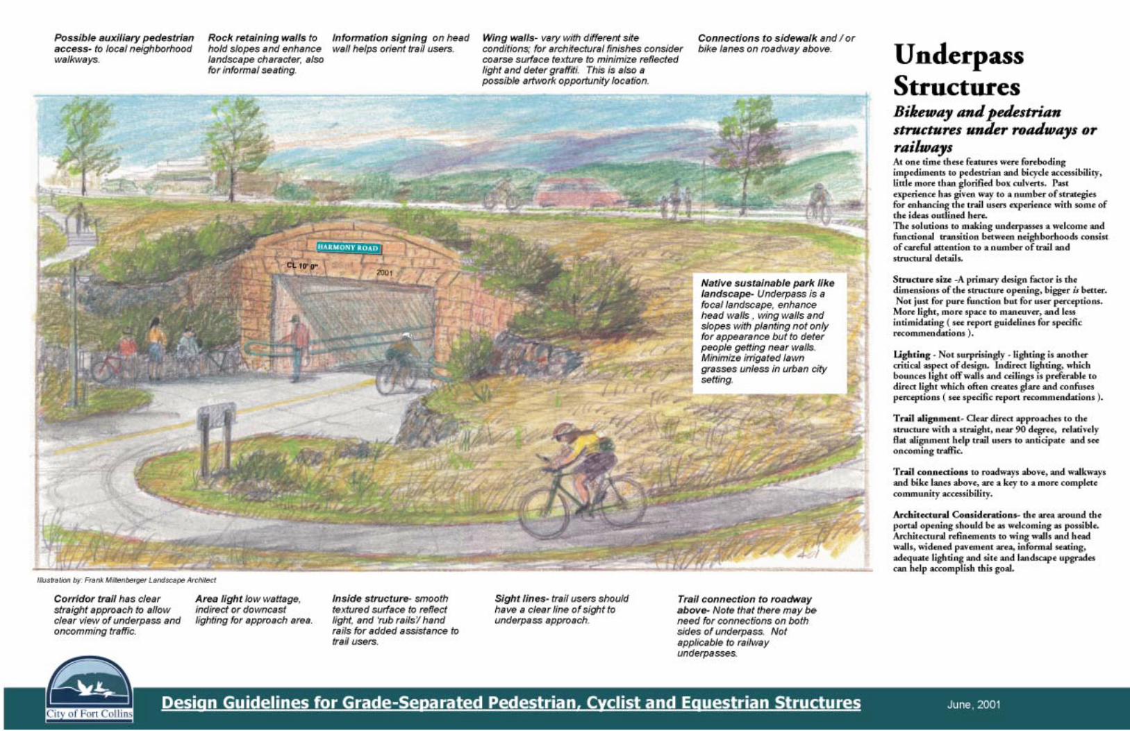


PHOTO EXAMPLES OF GUIDELINE INTENT
Design Guidelines forGrade-Separated Pedestrian, Cyclist
and Equestrian Structures
September 2001 Page 22
�����������������
Felsburg Holt & Ullevig
AAeesstthheettiicc AAppppeeaall
LLooccaattiioonn RReeffeerreennccee
AAmmppllee SSttrruuccttuurree WWiiddtthh
MMeeddiiaann SSkkyylliigghhtt
LLaannddssccaappee AAmmeenniittyy

PHOTO EXAMPLES OF GUIDELINE INTENT
September 2001 Page 23
Design Guidelines forGrade-Separated Pedestrian, Cyclist
and Equestrian Structures�����������������
Felsburg Holt & Ullevig
DDeeccoorraattiivvee RRaaiilliinngg
EExxtteerrnnaall AArrttwwoorrkk
IInntteerrnnaall AArrttwwoorrkk
RReesstt BBeenncchh

PHOTO EXAMPLES OF GUIDELINE INTENT
September 2001 Page 24
Design Guidelines forGrade-Separated Pedestrian, Cyclist
and Equestrian Structures�����������������
Felsburg Holt & Ullevig
PPrrootteeccttiivvee RRaaiilliinngg
DDeeccoorraattiivvee WWaallll TTrreeaattmmeenntt
PPrrootteeccttiivvee RRaaiilliinnggBBeettwweeeenn UUssaabbllee
PPaatthh aannddDDrraaiinnaaggee FFaacciilliittyy
4455°° TToopp CCoorrnneerr
IInntteerriioorr DDrraaiinnaaggee PPllaann
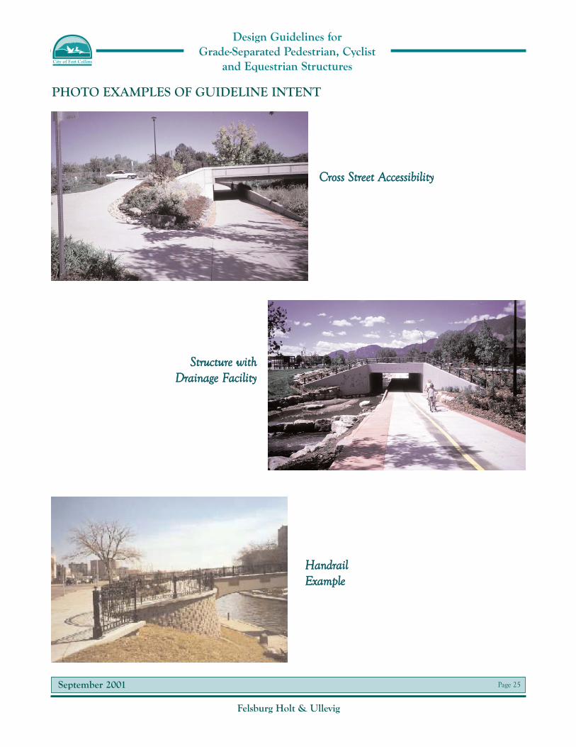
PHOTO EXAMPLES OF GUIDELINE INTENT
September 2001 Page 25
Design Guidelines forGrade-Separated Pedestrian, Cyclist
and Equestrian Structures�����������������
Felsburg Holt & Ullevig
CCrroossss SSttrreeeett AAcccceessssiibbiilliittyy
SSttrruuccttuurree wwiitthhDDrraaiinnaaggee FFaacciilliittyy
HHaannddrraaiillEExxaammppllee

September 2001 Page 26
Design Guidelines forGrade-Separated Pedestrian, Cyclist
and Equestrian Structures�����������������
Felsburg Holt & Ullevig
AArrttwwoorrkk AAmmeenniittyy
OOvveerrppaassss wwiitthh EElleevvaattoorr
OOvveerrhheeaadd LLiigghhttiinngg
PPrrootteeccttiivvee SSiiddee BBaarrrriieerr
PHOTO EXAMPLES OF GUIDELINE INTENT


