
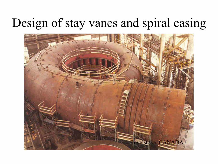
Design of stay vanes and spiral casing
Revelstoke, CANADA
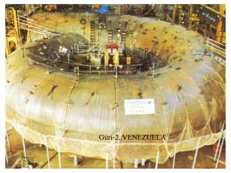
Guri-2, VENEZUELA

Aguila, ARGENTINA
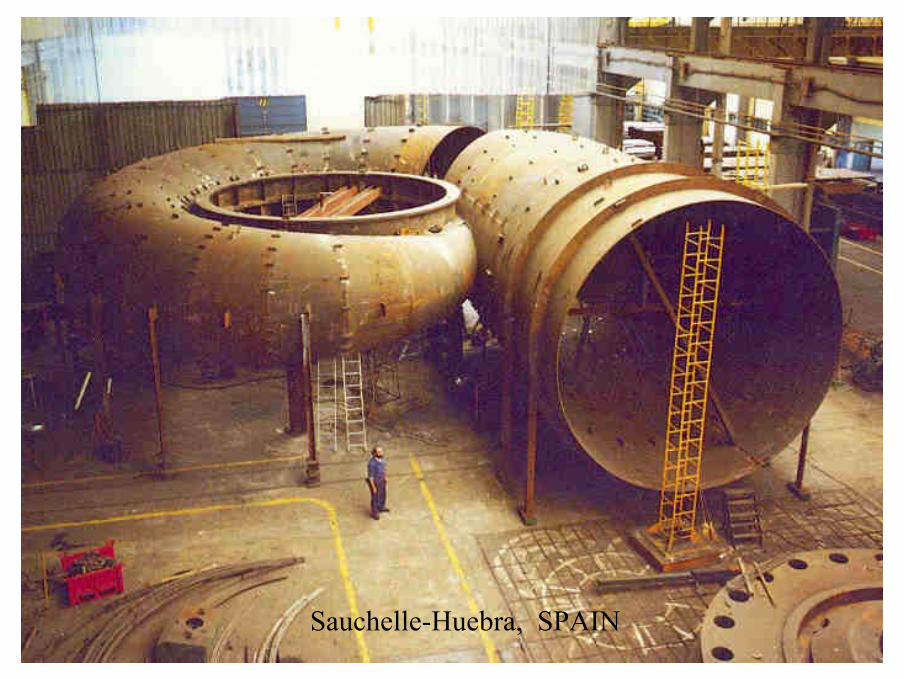
Sauchelle-Huebra, SPAIN
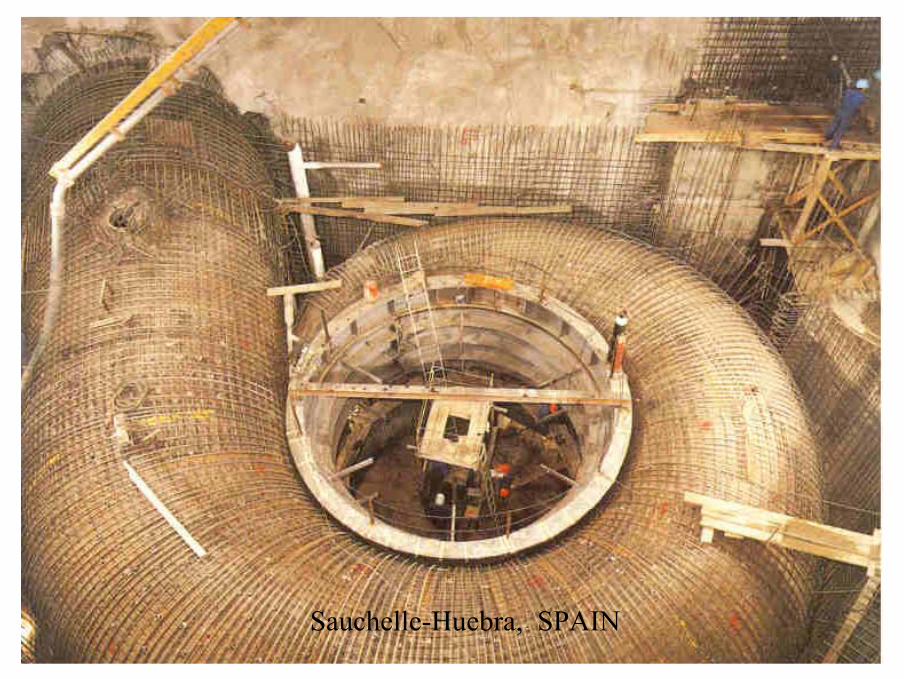
Sauchelle-Huebra, SPAIN
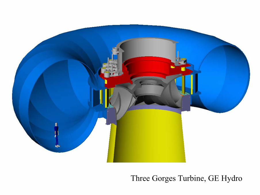
Three Gorges Turbine, GE Hydro
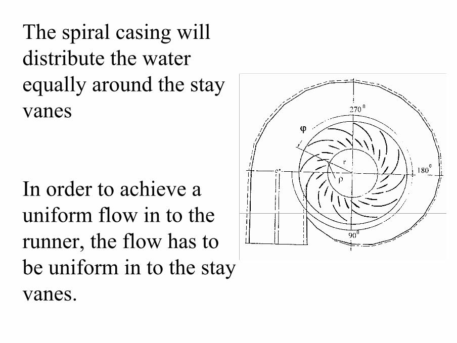
The spiral casing will distribute the water equally around the stay vanes
In order to achieve a uniform flow in to the runner, the flow has to be uniform in to the stay vanes.
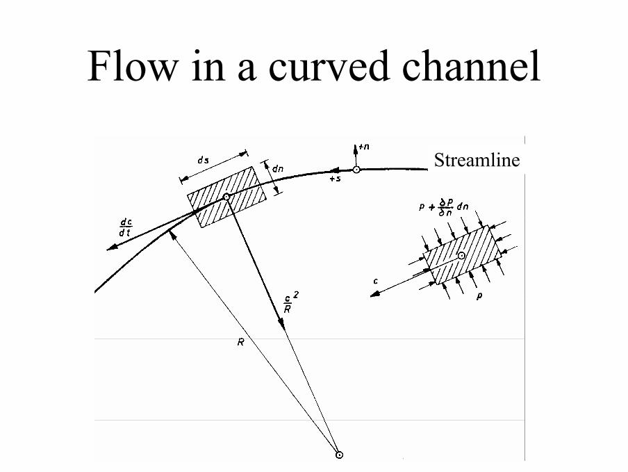
Flow in a curved channel
Streamline
StreamlineStreamline
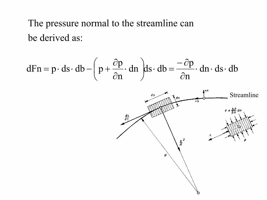
The pressure normal to the streamline can be derived as:
dbdsdnnpdbdsdn
nppdbdspdFn ⋅⋅⋅
∂∂−
=⋅
⋅
∂∂
+−⋅⋅=
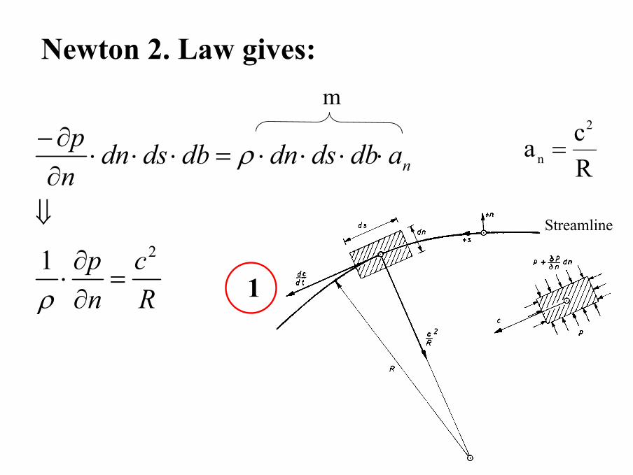
Newton 2. Law gives:
StreamlineStreamline
Rc
np
adbdsdndbdsdnnp
n
21=
∂∂⋅
⇓
⋅⋅⋅⋅=⋅⋅⋅∂∂−
ρ
ρ Rca
2
n =
1
m
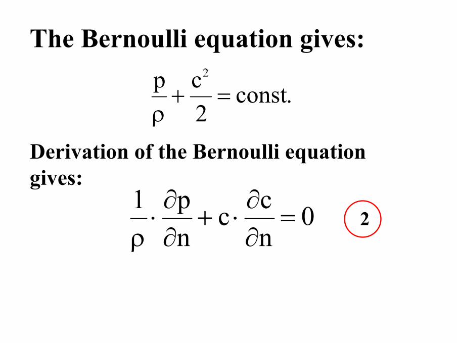
The Bernoulli equation gives:
.const2cp 2
=+ρ
Derivation of the Bernoulli equation gives:
0ncc
np1
=∂∂⋅+
∂∂⋅
ρ2
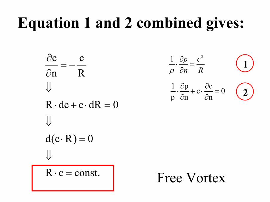
Equation 1 and 2 combined gives:
.constcR
0)Rc(d
0dRcdcR
Rc
nc
=⋅⇓
=⋅⇓
=⋅+⋅⇓
−=∂∂
Free Vortex
Rc
np 21=
∂∂⋅
ρ
0ncc
np1
=∂∂⋅+
∂∂⋅
ρ 2
1
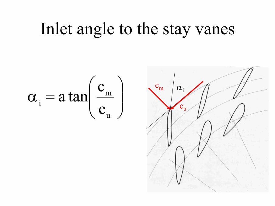
Inlet angle to the stay vanes
αicm
cu
=α
u
mi c
ctana
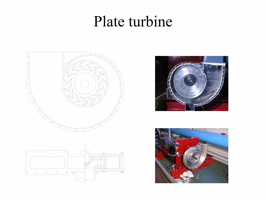
Plate turbine
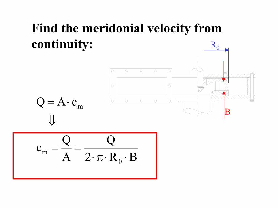
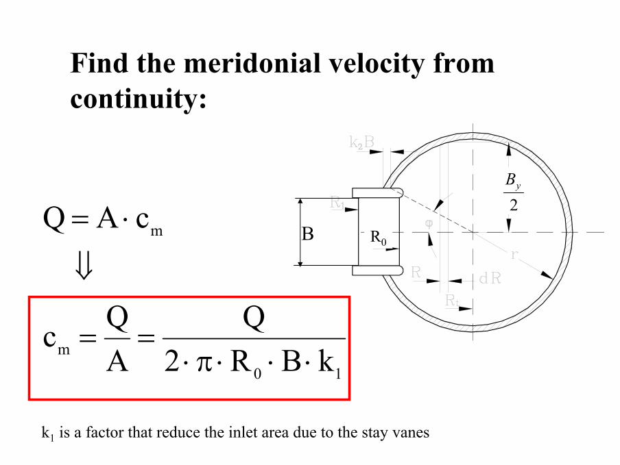
Find the meridonial velocity from continuity:
BR2Q
AQc
cAQ
0m
m
⋅⋅π⋅==
⇓
⋅=B
R0
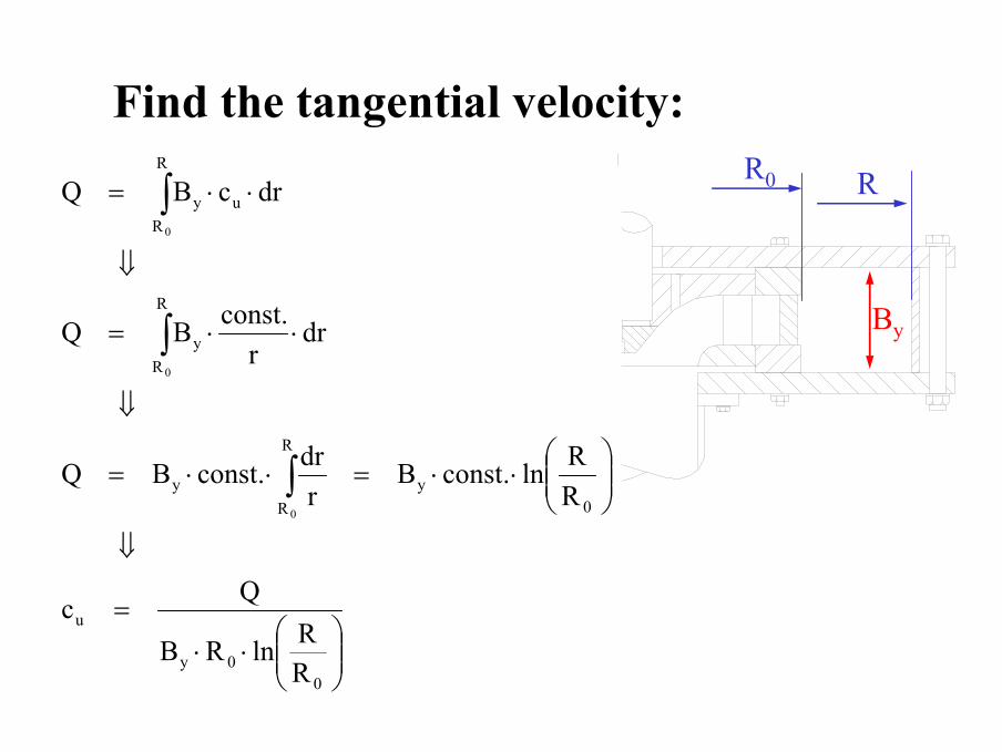
Find the tangential velocity:
⋅⋅
=
⇓
⋅⋅=⋅⋅=
⇓
⋅⋅=
⇓
⋅⋅=
∫
∫
∫
00y
u
0y
R
Ry
R
Ry
u
R
Ry
RRlnRB
Qc
RRln.constB
rdr.constBQ
drr
.constBQ
drcBQ
0
0
0
By
R0 R
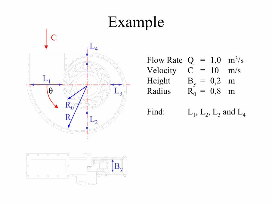
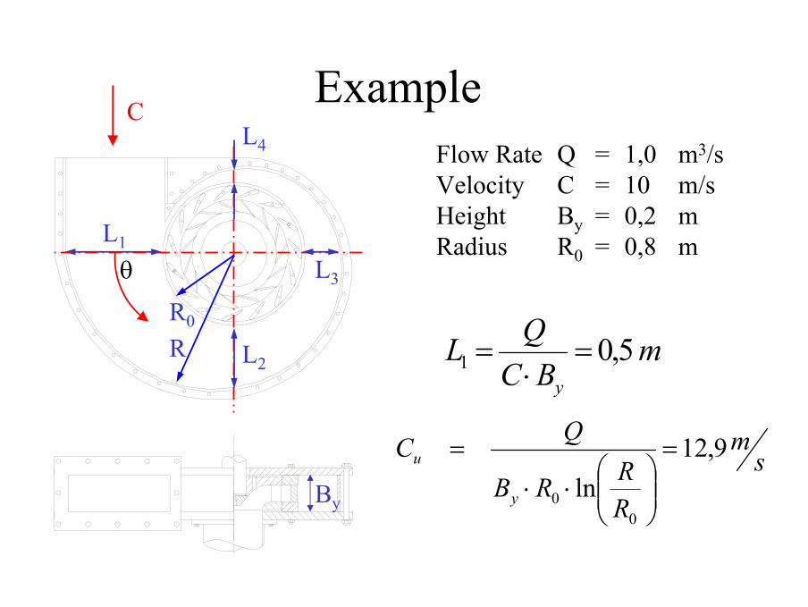
Example
By
Flow Rate Q = 1,0 m3/sVelocity C = 10 m/sHeight By = 0,2 mRadius R0 = 0,8 m
Find: L1, L2, L3 and L4
L1
θ
C
L3
L2
L4
R0
R
Example
By
Flow Rate Q = 1,0 m3/sVelocity C = 10 m/sHeight By = 0,2 mRadius R0 = 0,8 mL1
θ
C
L3
L2
L4
R0
R
sm
RRRB
QC
y
u 9,12ln
00
=
⋅⋅
=
mBCQL
y
5,01 =⋅
=
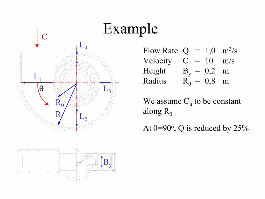
Example
By
Flow Rate Q = 1,0 m3/sVelocity C = 10 m/sHeight By = 0,2 mRadius R0 = 0,8 m
We assume Cu to be constant along R0.
At θ=90o, Q is reduced by 25%
L1
θ
C
L3
L2
L4
R0
R
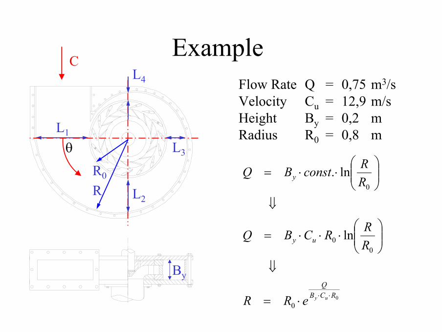
Example
By
Flow Rate Q = 0,75 m3/sVelocity Cu = 12,9 m/sHeight By = 0,2 mRadius R0 = 0,8 mL1
θ
C
L3
L2
L4
R0
R
00
00
0
ln
ln.
RCBQ
uy
y
uyeRR
RRRCBQ
RRconstBQ
⋅⋅⋅=
⇓
⋅⋅⋅=
⇓
⋅⋅=
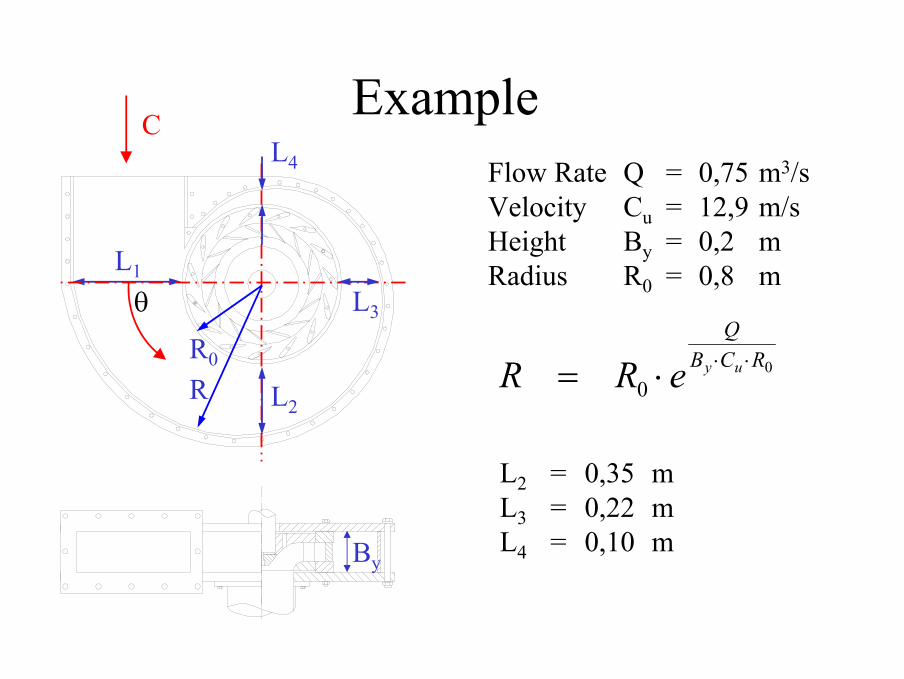
Example
By
Flow Rate Q = 0,75 m3/sVelocity Cu = 12,9 m/sHeight By = 0,2 mRadius R0 = 0,8 mL1
θ
C
L3
L2
L4
R0
R0
0RCB
Q
uyeRR ⋅⋅⋅=
L2 = 0,35 mL3 = 0,22 mL4 = 0,10 m
Find the meridonial velocity from continuity:
10m
m
kBR2Q
AQc
cAQ
⋅⋅⋅π⋅==
⇓
⋅=R0B
k1 is a factor that reduce the inlet area due to the stay vanes
2yB
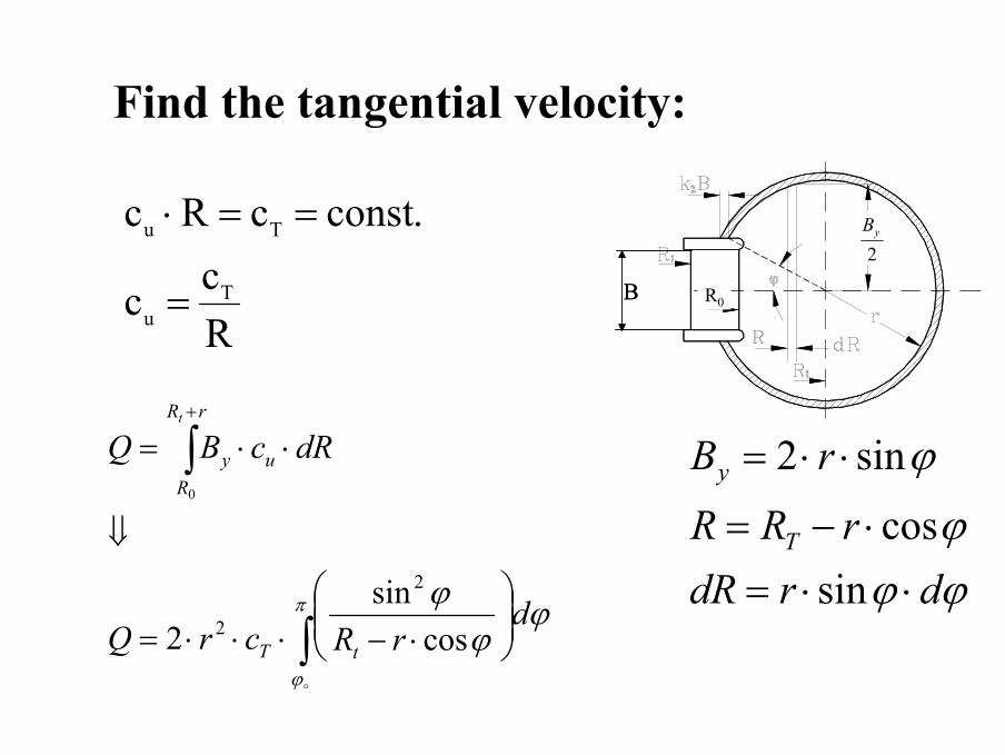
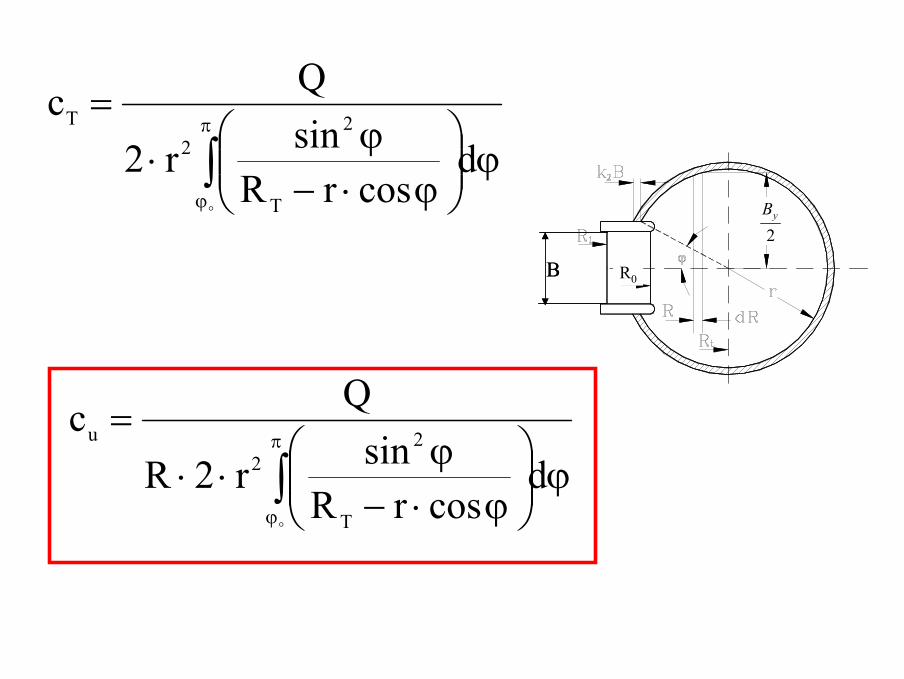
Find the tangential velocity:
Rcc
.constcRc
Tu
Tu
=
==⋅
∫
∫
⋅−⋅⋅⋅=
⇓
⋅⋅=+
π
ϕ
ϕϕ
ϕ drRcrQ
dRcBQ
tT
u
rR
Ry
t
cossin
2
2
2
0
R0B R0B
ϕϕϕ
ϕ
drdRrRR
rB
T
y
⋅⋅=⋅−=
⋅⋅=
sincos
sin2
2yB
ϕ
ϕ⋅−
ϕ⋅
=
∫π
ϕ
dcosrR
sinr2
Qc
T
22
T
R0B R0B
ϕ
ϕ⋅−
ϕ⋅⋅
=
∫π
ϕ
dcosrR
sinr2R
Qc
T
22
u
2yB
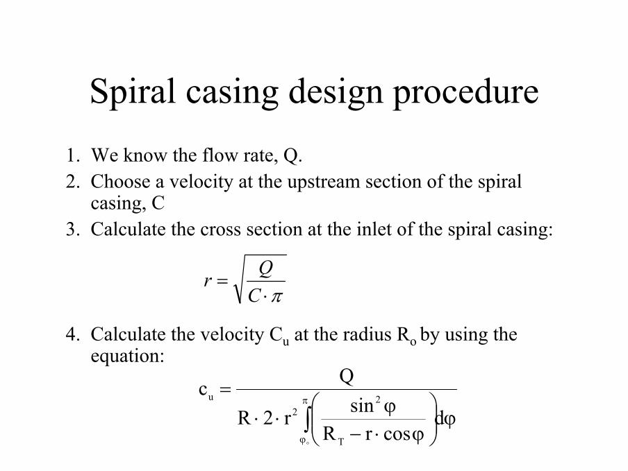
Spiral casing design procedure1. We know the flow rate, Q. 2. Choose a velocity at the upstream section of the spiral
casing, C3. Calculate the cross section at the inlet of the spiral casing:
4. Calculate the velocity Cu at the radius Ro by using the equation:
π⋅=CQr
ϕ
ϕ⋅−
ϕ⋅⋅=
∫π
ϕ
dcosrR
sinr2R
Qc
T
22
u
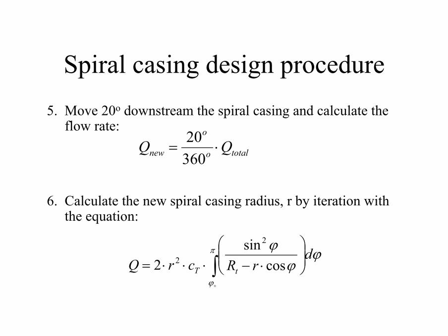
Spiral casing design procedure5. Move 20o downstream the spiral casing and calculate the
flow rate:
6. Calculate the new spiral casing radius, r by iteration with the equation:
totalo
o
new QQ ⋅=36020
∫
⋅−⋅⋅⋅=
π
ϕ
ϕϕ
ϕ drRcrQ tT cos
sin2
2
2
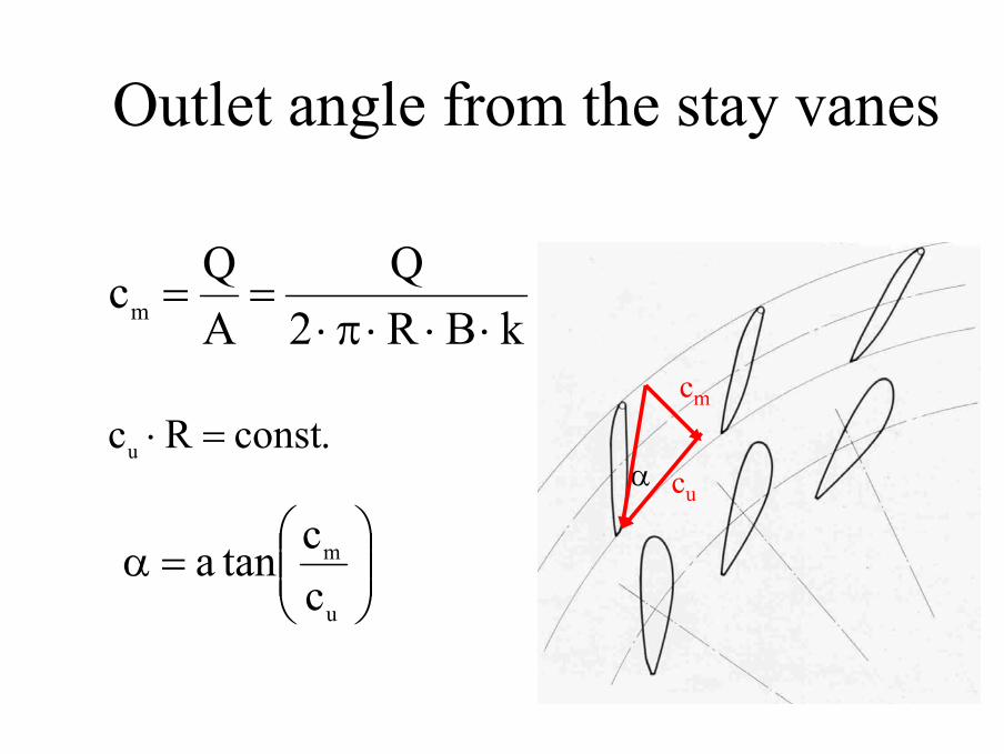
Outlet angle from the stay vanes
α
cm
cu
=α
u
m
cctana
.constRcu =⋅
kBR2Q
AQcm ⋅⋅⋅π⋅==
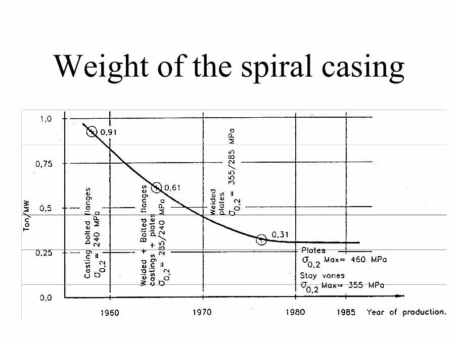
Weight of the spiral casing
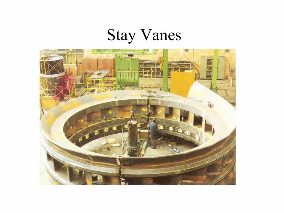
Stay Vanes
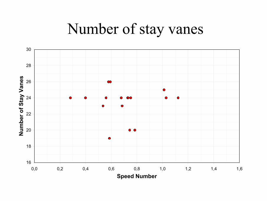
Number of stay vanes
16
18
20
22
24
26
28
30
0,0 0,2 0,4 0,6 0,8 1,0 1,2 1,4 1,6
Speed Number
Num
ber o
f Sta
y Va
nes
Design of the stay vanes
• The stay vanes have the main purpose of keeping the spiral casing together
• Dimensions have to be given due to the stresses in the stay vane
• The vanes are designed so that the flow is not disturbed by them
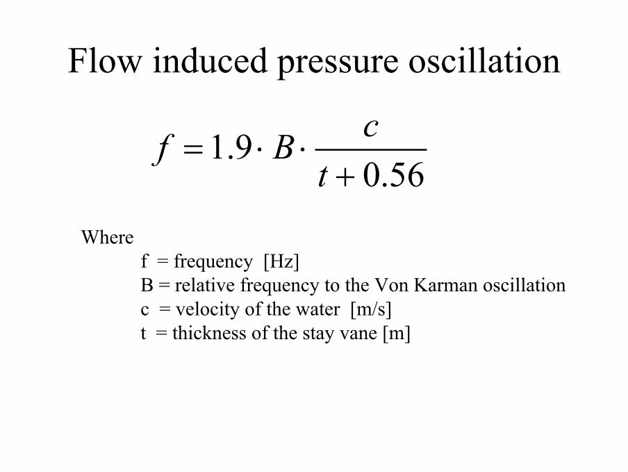
Flow induced pressure oscillation
56.09.1
+⋅⋅=tcBf
Where f = frequency [Hz]B = relative frequency to the Von Karman oscillationc = velocity of the water [m/s]t = thickness of the stay vane [m]
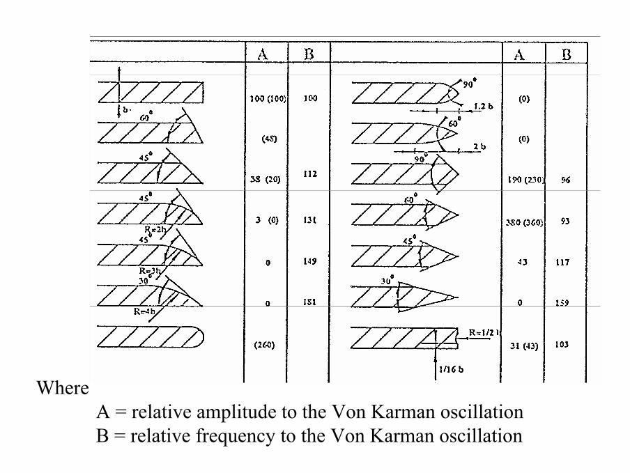
Where A = relative amplitude to the Von Karman oscillationB = relative frequency to the Von Karman oscillation


