

© MTU Friedrichshafen GmbH | All rights reserved | STRICTLY CONFIDENTIAL
6th CIMAC CASCADES
Development of a Gas Propulsion
System for Harbour Tug Applications
Dr. Wolfgang Fimml
FEBRUARY 26 – 27, 2015 | GRAZ, AUSTRIA

Page 2
© MTU Friedrichshafen GmbH | All rights reserved | STRICTLY CONFIDENTIAL
good response characteristic
and load acceptance
Off-Highway Applications
Requirements
high
time-between-overhaul
(TBO)
restricted installation
space, high power to
weight ratio
low cooling
demand
high availability
and reliability
good
serviceability
low fuel consumption,
low life-cycle-costs (LCC)
stringent emission
requirements
Can a gas fuelled engine meet these requirements?
Development of a Gas Propulsion System for Harbour Tug Applications | CIMAC CASCADES 2015 | Fimml | 27.02.2015

Page 3
© MTU Friedrichshafen GmbH | All rights reserved | STRICTLY CONFIDENTIAL
Developing LNG*-Infrastructure
Emission Regulations (ECA**) Large Reserves
Gas for mobile applications
Key Drivers
* LNG: Liquified Natural Gas
** ECA: Emission Controlled Area
Development of a Gas Propulsion System for Harbour Tug Applications | CIMAC CASCADES 2015 | Fimml | 27.02.2015
Low Gas Price

Page 4
© MTU Friedrichshafen GmbH | All rights reserved | STRICTLY CONFIDENTIAL
Engine Concepts for Marine Applications
What are the options for IMO3?
Otto-Gas (l>1) Dual Fuel
Otto-Gas (l=1) Gas Diesel
Engine Engine
Engine Engine
Gas (5…10 bar) Gas (5…10 bar)
Diesel
Gas (5…10 bar)
Diesel
Gas (> 250 bar)
OxiCat OxiCat
SCR DPF TWC
SCR DPF
only
EPAT4
only
EPAT4
for IMO3 / EPAT4
Diesel Operation
Development of a Gas Propulsion System for Harbour Tug Applications | CIMAC CASCADES 2015 | Fimml | 27.02.2015

Page 5
© MTU Friedrichshafen GmbH | All rights reserved | STRICTLY CONFIDENTIAL
Drivers for Gas – Emissions of Green House Gases
Comparison of Gas & Diesel Engines
0
100
200
300
400
500
600
700
M63-Diesel Enginetodays standard
Otto Gas (l>1) Enginefor IMO3
CO
2 (
eq
uiv
ale
nt)
[g
/kW
h]
CO2 due to combustion CO2 equivalent for methane slip
Gas engines have the potential to reduce GHG-emissions.
Malus due to
methane slip
(GWP 25)
Bonus due to
C/H ratio of
LNG
Benefit up
to -11% *
GWP - Global Warming Potential assumption: 1A load profile & same efficiency (Diesel and Otto Gas in operating cycle)
Equivalent CO2 emissions in TUG operating cycle
Development of a Gas Propulsion System for Harbour Tug Applications | CIMAC CASCADES 2015 | Fimml | 27.02.2015
M63-Diesel Engine
todays standard Otto Gas (l>1) Engine
for IMO3
Page 6
© MTU Friedrichshafen GmbH | All rights reserved | STRICTLY CONFIDENTIAL
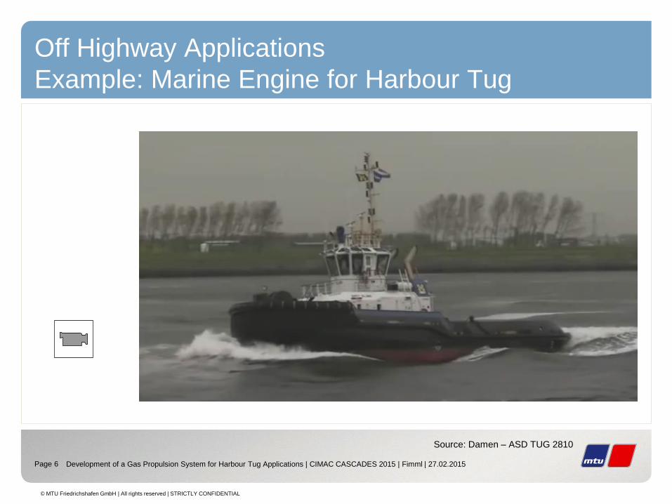
Off Highway Applications
Example: Marine Engine for Harbour Tug
Source: Damen – ASD TUG 2810
Development of a Gas Propulsion System for Harbour Tug Applications | CIMAC CASCADES 2015 | Fimml | 27.02.2015

Page 7
© MTU Friedrichshafen GmbH | All rights reserved | STRICTLY CONFIDENTIAL
Gas Propulsion System for Harbour Tug
Applications
Example : Design of the RSD TUG 2512 CNG
CNG - Tank
2 x MTU 16V4000
Gas Engine
2 x Rolls-Royce
Thruster
Source: Damen
Development of a Gas Propulsion System for Harbour Tug Applications | CIMAC CASCADES 2015 | Fimml | 27.02.2015

Page 8
© MTU Friedrichshafen GmbH | All rights reserved | STRICTLY CONFIDENTIAL
Engine Design
S4000 Gas Engine for Marine Applications
Engineering Targets:
Application Marine Commercial
Emissions IMO3 / EPA T4
& low Methane Slip
Base-Engine S4000 M63
Bore: 170 mm
Stroke: 210 mm
Combustion Otto-Gas (l>1)
Engine Mapping like M63
Engine Dynamics like M63
Safety concept IGF-Code: Gas-safe
Multi Point Injection (MPI)
Double walled gas supply
Development of a Gas Propulsion System for Harbour Tug Applications | CIMAC CASCADES 2015 | Fimml | 27.02.2015
Page 9
© MTU Friedrichshafen GmbH | All rights reserved | STRICTLY CONFIDENTIAL
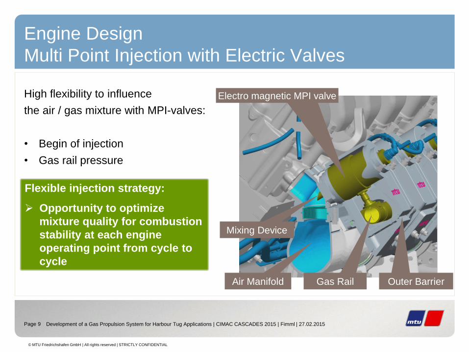
Engine Design
Multi Point Injection with Electric Valves
High flexibility to influence
the air / gas mixture with MPI-valves:
• Begin of injection
• Gas rail pressure
Gas Rail Outer Barrier Air Manifold
Mixing Device
Flexible injection strategy:
Opportunity to optimize
mixture quality for combustion
stability at each engine
operating point from cycle to
cycle
Electro magnetic MPI valve
Development of a Gas Propulsion System for Harbour Tug Applications | CIMAC CASCADES 2015 | Fimml | 27.02.2015

Page 10
© MTU Friedrichshafen GmbH | All rights reserved | STRICTLY CONFIDENTIAL
Thermodynamic Design
Required Engine Dynamics
Data logging in a TUG boat - „Standard“ - TUG Manoeuvers
data logging: engine runtime
approximately 6h
Source: Damen
Typical TUG manoeuvre: acceleration along propeller curve
Development of a Gas Propulsion System for Harbour Tug Applications | CIMAC CASCADES 2015 | Fimml | 27.02.2015
Speed [rpm]
En
gin
e t
orq
ue
[N
m]

Page 11
© MTU Friedrichshafen GmbH | All rights reserved | STRICTLY CONFIDENTIAL
Thermodynamic Design
Required Engine Dynamics
Manoeuver Goal: Realization of minimal
stopping distance to avoid crash!
“Worst Case“ TUG Manoeuver - Emergency Crash Stop
Source: Damen
1. Start condition: Sailing full speed ahead Engine Speed: maximum
Engine Torque: high
2. Emergency Stop: Turn the thrusters 180° against original direction
thrust reversal Engine Speed: high
Engine Torque: maximum
3. Station keeping: Thrusters in neutral position Engine Speed: low
Engine Torque: low
Development of a Gas Propulsion System for Harbour Tug Applications | CIMAC CASCADES 2015 | Fimml | 27.02.2015

Page 12
© MTU Friedrichshafen GmbH | All rights reserved | STRICTLY CONFIDENTIAL
Start:
full speed ahead
End:
station keeping
thrust reversal
maximum torque
Speed [rpm]
En
gin
e t
orq
ue
[N
m]
10 20 30 40 50 60 70time [s]
Moto
rdre
hzahl_
EC
U [rp
m]
400
600
800
1000
1200
1400
1600
1800
2000
Erdgas
MZ70
10 20 30 40 50 60 70
time [s]D
rehm
om
ent_
Pru
efs
tand [N
m]
0
1000
2000
3000
4000
5000
6000
7000
8000
9000
10000
FP205_K9M09.dat
FP203_K8M10.dat
En
gin
e t
orq
ue [
Nm
] S
peed
[rp
m]
Time [s]
Time [s]
Thermodynamic Design
Required Engine Dynamics
Data logging in a TUG boat - „Worst Case“ - TUG Manoeuver *
Development of a Gas Propulsion System for Harbour Tug Applications | CIMAC CASCADES 2015 | Fimml | 27.02.2015
„Worst Case“ TUG manoeuvre: Emergency crash stop
* Data from crash stop manoeuvre with DAMEN ASD Tug 2411

Page 13
© MTU Friedrichshafen GmbH | All rights reserved | STRICTLY CONFIDENTIAL
Real engine operating in a vessel can be tested.
Simulation of TUG maneuver with ship model Hardware in the Loop
Engine Dynamics
Investigations of Real Vessel Operation on Test Bed
real time ship model @ test bed
vessel speed
engine speed
propeller torque engine torque
propeller speed
thrust
engine @ high transient test bed
resulting driving curve
Source: Damen
Development of a Gas Propulsion System for Harbour Tug Applications | CIMAC CASCADES 2015 | Fimml | 27.02.2015

Page 14
© MTU Friedrichshafen GmbH | All rights reserved | STRICTLY CONFIDENTIAL
10 20 30 40 50 60 70time [s]
Moto
rdre
hzahl_
EC
U [rp
m]
400
600
800
1000
1200
1400
1600
1800
2000
Erdgas
MZ70
10 20 30 40 50 60 70
time [s]
Dre
hm
om
ent_
Pru
efs
tand [N
m]
0
1000
2000
3000
4000
5000
6000
7000
8000
9000
10000
FP205_K9M09.dat
FP203_K8M10.dat
En
gin
e t
orq
ue [
Nm
] S
peed
[rp
m]
Time [s]
Time [s]
Engine Dynamics
Investigations of Real Vessel Operation on Test Bed
HIL testing offers significant
advantages in engine and software
development!
Results: Hardware in the Loop Emergency Crash Stop
CS
Development of a Gas Propulsion System for Harbour Tug Applications | CIMAC CASCADES 2015 | Fimml | 27.02.2015
Page 15
© MTU Friedrichshafen GmbH | All rights reserved | STRICTLY CONFIDENTIAL
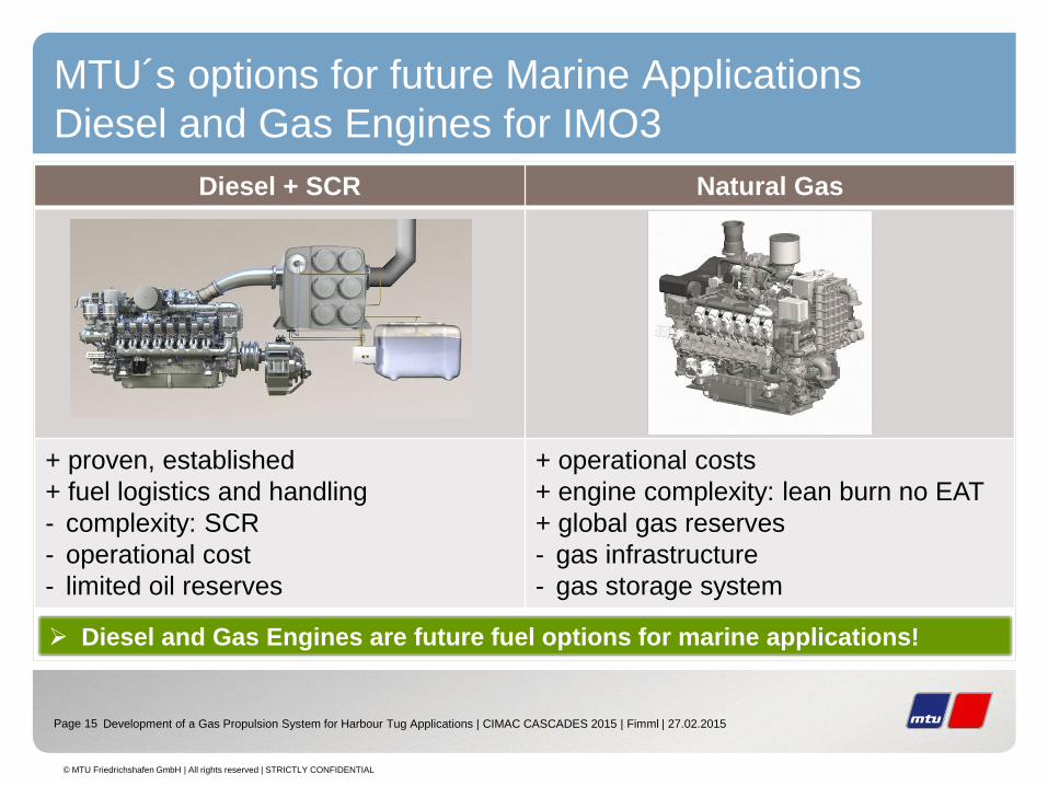
MTU´s options for future Marine Applications
Diesel and Gas Engines for IMO3
Diesel + SCR Natural Gas
Diesel and Gas Engines are future fuel options for marine applications!
Diesel + SCR Natural Gas
+ proven, established
+ fuel logistics and handling
- complexity: SCR
- operational cost
- limited oil reserves
+ operational costs
+ engine complexity: lean burn no EAT
+ global gas reserves
- gas infrastructure
- gas storage system
Development of a Gas Propulsion System for Harbour Tug Applications | CIMAC CASCADES 2015 | Fimml | 27.02.2015

© MTU Friedrichshafen GmbH | All rights reserved | STRICTLY CONFIDENTIAL
Thank you very much for your attention.


