
© 2015, IJARCSSE All Rights Reserved Page | 183
Volume 5, Issue 7, July 2015 ISSN: 2277 128X
International Journal of Advanced Research in Computer Science and Software Engineering Research Paper Available online at: www.ijarcsse.com
Digital Image Sobel Edge Detection Using FPGA 1Nasseer M. Basheer,
2Ashty M. Aaref,
3Dhafer J. Ayyed
1 Ph.D., Lecturer, Technical College/Mosul, Iraq
2 Ph.D., Software Engineering Department, College Technology/Kirkuk, Iraq
3 M. Tech Student, Computer Engineering Department Technical College/Mosul, Iraq
Abstract— Edge detection is one of the important stages in image processing. The Sobel edge detection algorithm is
the most widely used edge detection algorithm due to Characteristics. In this paper, the Sobel edge detection is taken
into consideration. The software is implemented using MATLAB, also the Sobel edge detection algorithm is
implemented and presented on Spartan3E (XC3S1600E) FPGA by ISE12.1. This paper mainly used the Sobel
operator method to do edge detection processing on the gray scale images. It has been proven by the results we have
obtained that the edge detection mathematical method using MATLAB software and FPGA is very good in the
analysing the image and the results reach to 99%. A 256×256 Gray Scale input image is used in this work.
Keywords— Edge Detection, Edges, mask, threshold, Sobel Operator, FPGA.
I. INTRODUCTION
Digital image consists of a finite number of components, each of which has a special place or position and value.
These components are the image elements or pixels [1]. Edge detection is the most common way for detecting
discontinuities in gray scale images. An edge is defined as a set connected pixels that lie on a particular boundary
between two regions [2]. Edge detection is the name for a set of mathematical methods which aim at identifying points in
a digital image at which the image brightness changes sharply or, more formally, has discontinuities. The points at which
image brightness changes sharply are typically organized into a set of curved line segments termed edges [3].
Edge detection is one of the tool that used in image processing, basically for feature detection and extraction, which aims
to identify points in a digital image where brightness of image changes sharply and find discontinuities [4]. The general
methods of edge detection under the derivatives are first order derivative (gradient method) and second order derivative.
1- First order derivative operator's (gradient method) is contain Robert Detector,Prewitt Detector and Sobel Detector
where: Robert Detector : It is gradient based operator. It firstly computes the sum of the squares of the difference
between diagonally adjacent pixels through discrete differentiation and then calculate approximate gradient of the
image. The input image is convolved with the default kernels of operator and gradient magnitude and directions are
computed. It uses following 2 x2 two kernels as shown in Fig. 1:
Fig 1 : Convolution masks for Roberts operator [5]
, Prewitt Detector: The function of Prewitt edge detector is almost same as of Sobel detector but have different kernels
as shown in Fig. 2:
Fig 2 : Convolution masks for Prewitt operator [5]
And Sobel Detector: is one of the most frequently used in edge detection . Sobel edge detection can be implemented by
filtering an image with left mask or kernel. Filter the image again with the other mask. After this square of the pixels
values of each filtered image. Now add the two results and compute their root. The 3 × 3 convolution masks for the Sobel
based operator as shown in Fig. 3.
Fig 3 : Convolution masks for the Sobel operator [1,6]
Gx= -1 0
Gy= 0 -1
0 1 1 0
-1 0 1 1 1 1
Gx= -1 0 1 Gy= 0 0 0
-1 0 1 -1 -1 -1
-1 -2 -1 -1 0 1
Gx= 0 0 0 Gy= -2 0 2
1 2 1 -1 0 1

Basheer et al., International Journal of Advanced Research in Computer Science and Software Engineering 5(7),
July- 2015, pp. 183-190
© 2015, IJARCSSE All Rights Reserved Page | 184
Sobel has two main advantages: it has some smoothing effect to the random noise of the image:
1) Since the introduction of the average factor, it has some smoothing effect to the random noise of the image.
2) Because it is the differential of two rows or two columns, so the element of the edge on both sides ha been
enhanced, so that the edge seems thick and bright.
The Sobel operator is used mostly although it is slower than the Roberts cross operator, because its horizontal and
vertical kernels smooth the input image and makes operator less sensitive to noise. The reason for using Sobel operator is
that it has relatively small masks compare to other operators [7].
2- Second order derivative operator's [5] is contain Laplacian of Gaussian [8]:
The Laplacian is a 2-D isotropic measure of the 2nd spatial derivative of an image. The Laplacian of an image highlights
regions of rapid intensity change and is therefore often used for edge detection. The Laplacian is often applied to an
image that has first been smoothed with something approximating a Filtering order to reduce its sensitivity to noise. The
operator normally takes a single gray level image as input and produces another gray level image as output.
The Laplacian L(x,y) of an image with pixel intensity values I(x,y) is given below:
L(x, y) =𝜕2𝐼
𝜕𝑥 2 +𝜕2𝐼
𝜕𝑦 2
Since the input image is represented as a set of discrete pixels, we have to find a discrete convolution kernel that
can approximate the second derivatives in the definition of the Laplacian. Three commonly used small kernels are shown
in Fig. 4.
Fig 4 : Three commonly used discrete approximations to the Laplacian filter [8].
Edges characterize boundaries and are therefore considered for prime importance in image processing. An edge is seen at
a place where an image has a strong intensity contrast. Edges could also be represented by a difference in color, without
any difference in intensity [3].
Edges include large amount of important information about the image. The changes in pixel intensity describe the
boundaries of objects in an image [9].
Edge detection is one of the most commonly used operations in image processing, which is the subject of research for
many researchers, for example, P.Sivarama Prasad, et al.2013 [10], proposed an FPGA based hardware accelerator for
extracting the information from the screen image. The Xilinx Spartan-6 FPGA board was used for realizing
morphological image processing modules along with Microblaze soft core. The Microblaze software performed the
control operation and provides 100 Mbps Ethernet access to PC. The image processing modules were verified working at
100 MHz clock with chipscope occupying 70% of the selected Spartan-6 LX45 device along with Microblaze soft core.
In [11] Manoj T H et al. made a Survey and Evaluation of Edge Detection Operators. A combination of different edge
detection algorithm is described to extract the text from natural images. Combine Edge Detection method locates the
edges better compare to other classical edge detectors when extraction of connected component.
In this paper Sobel edge detection algorithm is used to do edge detection processing on the 256×256 Gray Scale Image is
done by MATLAB program then it is done by Spartan3E (XC3S1600E) FPGA by ISE12.1, finally comparing between
MATLAB and FPGA results is also done.
II. SOBEL EDGE DETECTION OPERATOR
In case of Sobel Edge Detection, there are two masks, one mask identifies the horizontal edges and the other mask
identifies the vertical edges. Each of the masks has the effect of calculating the gradient in both vertical and horizontal
direction. These Sobel masks are convolved with smoothed image and giving gradients in i and j directions is given by
[1]:
Gi=Gx*F(i,j) and Gj=Gy*F(i,j)
Sobel masks are showing in Fig. 5.
-1 -2 -1
-1 0 1
0 0 0 -2 0 2
1 2 1 -1 0 1
Fig 5 : Horizontal operator and Vertical operator [1]
Equation (1) shows convolution of input image with horizontal mask and Equation (2) shows convolution of image
with vertical mask [13].
Gx= 𝑓 𝑥 + 1, 𝑦 − 1 + 2𝑓 𝑥 + 1, 𝑦 + 𝑓 𝑥 + 1, 𝑦 + 1
− 𝑓 𝑥 − 1, 𝑦 − 1 + 2𝑓 𝑥 − 1, 𝑦 +
𝑓(𝑥 − 1, 𝑦 − 1) .... (1)
0 1 0
1 1 1
-1 2 -1
1 -4 1 1 -8 1 2 -4 2
0 1 0 1 1 1 -1 2 -1

Basheer et al., International Journal of Advanced Research in Computer Science and Software Engineering 5(7),
July- 2015, pp. 183-190
© 2015, IJARCSSE All Rights Reserved Page | 185
Gy= 𝑓 𝑥 − 1, 𝑦 − 1 + 2𝑓 𝑥, 𝑦 − 1 + 𝑓 𝑥 + 1, 𝑦 − 1
− 𝑓 𝑥 − 1, 𝑦 + 1 + 2𝑓 𝑥, 𝑦 + 1 +
𝑓(𝑥 + 1, 𝑦 + 1) .... (2)
These masks can then be combined together to find the absolute magnitude of the gradient at each point. The gradient
magnitude is given by [12]:
𝐺 = 𝐺𝑥2 + 𝐺𝑦2 .... (3)
III. THRESHOLDING
Thresholding is a relatively simple approach of image segmentation [5]. Thresholding becomes a simple but effective
tool to separate objects from the background [4]. The way to extract the object from the background is to select a
threshold T. Then, any point (x,y) in the image at which f (x,y) >T is called an object point; otherwise the point is called
a background. Segmented image f (x,y) can be represented as below [ 13 ]:
1 if F(x,y) ≥ T
F(x,y)=
....(4)
0 other wise
The simplest methods used to determine the threshold value and that have been applied in this thesis. (Mean image data
values are calculated as follows:
𝑇 =1
𝐻∗𝑊 𝑓 𝑖, 𝑗
𝑊
𝑗 =1
𝐻
𝑖=1 ….. (5)
H=high of image. W=width of image.
IV. IMPLEMENTATION OF IMAGE SOBEL EDGE DETECTION USING MATLAB The Implementation is explained in details in the flowing points:
1- Reading image: Sobel operator is used to detect edges of the test images used. This procedure is applied on more than one test image as
shown in Fig. 6. Firstly the image data is read as an array with the dimension of image size. The number of elements of
this array is calculated in order to resize the array of image to another array. The resizing that be used is (256×256) in
MATLAB program.
Fig 6 : Test images used:
(a) goldhill image (b) Lena image
2- Applying the convolution mask i and j on the input image.
The horizontal template and vertical template shown in Fig. 5 above are used to get convolution with input image by
using equation (1) and (2). The result matrix after this operation is got the same size of two gradients Matrix Gx and Gy
as the original image as shown in Fig. 7 and Fig. 8.
Fig 7 : (a) Lena image after (b) Lena image after
Convolving with the horizontal mask (Gx) Convolving with the vertical mask (Gy)
Fig 8 : (a) goldhill image after (b) goldhill image after
Convolving with the horizontal mask (Gx) Convolving with the vertical mask (Gy)
Basheer et al., International Journal of Advanced Research in Computer Science and Software Engineering 5(7),
July- 2015, pp. 183-190
© 2015, IJARCSSE All Rights Reserved Page | 186
3- Determine the gradient magnitude by computing equation (3) as shown above. The gradient magnitude is determent by squaring the pixels values of each filtered image, Then Adding of the two
results and computing their root to get the total gradient value (Gr) are done.
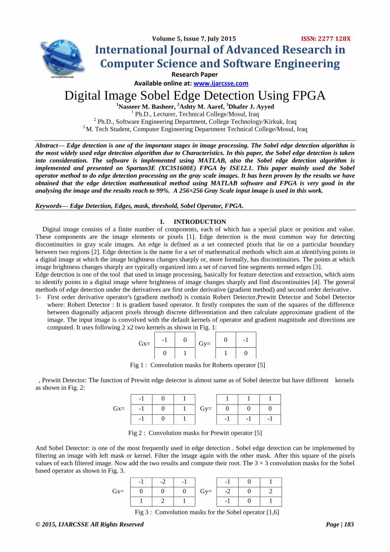
4- Compare the Gradient Magnitude with threshold value and find true edges.
Finally, the edges can be detected by applying the threshold by using equation (5) to the total gradient (Gr). If (Gr) is
greater than the threshold, then pixel should be identified an edge as shown in Figure (9). Else it's not identified as an
edge.
Fig 9: (a) Lena image after Sobel (b) goldhill image after Sobel
edge detection in MATLAB edge detection in MATLAB
V. EDGE DETECTION USING FPGA In this paper, the Sobel edge detection using FPGA is given with the required information about the FPGA Kit Used
and the method followed to get the Sobel edge detected image.
A. Spartan-3E (XC3S1600E) Starter Kit Field Programmable Gate Arrays (FPGAs) indicate reconfigurable computing technology, which is in some ways
very suitable for image processing [14]. Any future updates in the final product can be easily upgraded by simply
downloading a new application bit stream. However, the main advantage of FPGAs is the flexibility [15]. One of the
most advanced FPGA families in industry and education is the FPGA series produced by Xilinx. The designed
architectures are implemented in this thesis using one of the Xilinx FPGA devices, the SPARTAN-3E starter kit board
(supported with XC3S1600E device). The FPGA configuration is generally specified using a Hardware Description
Language (HDL) that is needed and important for describing the structure and functions of the system to be designed.
There are two major hardware description languages, VHDL and Verilog. The HDL that is used in this thesis to
implement the designed system is the VHDL, within the use of Xilinx ISE 12.1(Integrated Software Environment) as a
Electronic Design Automation (EDA) environment.
In this paper, the Spartan 3E (XC3S1600E) starter kit board is used for the implementation. Because this device contain a
block ram memory able to store a ( 256*256) pixel image. Where the total size of block Ram memory for this device is
648k.
B. Manipulating the Image for FPGA application
Fig 11: Design Methodology
Firstly, the test image is inputted with the help of MATLAB, which is by default an 8-bit gray scale image. The size of
each BRAM is 18 Kbit (2Kbit for carry +16Kbit for used) and the number of BRAMs in Spartan 3E (XC3S1600E) there
are 36 BRAM (total size = 648 Kbit). In this paper, the required BRAM memory size and number of used BRAM depend
on the size of used image as an equations below:
The required storage memory of used image Kbit=( image dimensions *8 )/1024 …..(6)
Number of BRAM used= the required storage memory of used image Kbit/16 Kbit ……(7)
The images that are used in this work an 8-bit gray scale with size 256×256 pixel. So that the required storage memory
of used image = 256*256 *8 /1024=512kbits and number of BRAM used= 512 Kbit/16 Kbit=32 BRAM, each BRAM
has only 16Kbit used for storing data.
1- Hexadecimal values: in this step the image is read and resized to store in (.Coe) file and this step is done by
converted each pixel in resized image to hexadecimal value then stored in (.Coe) file.
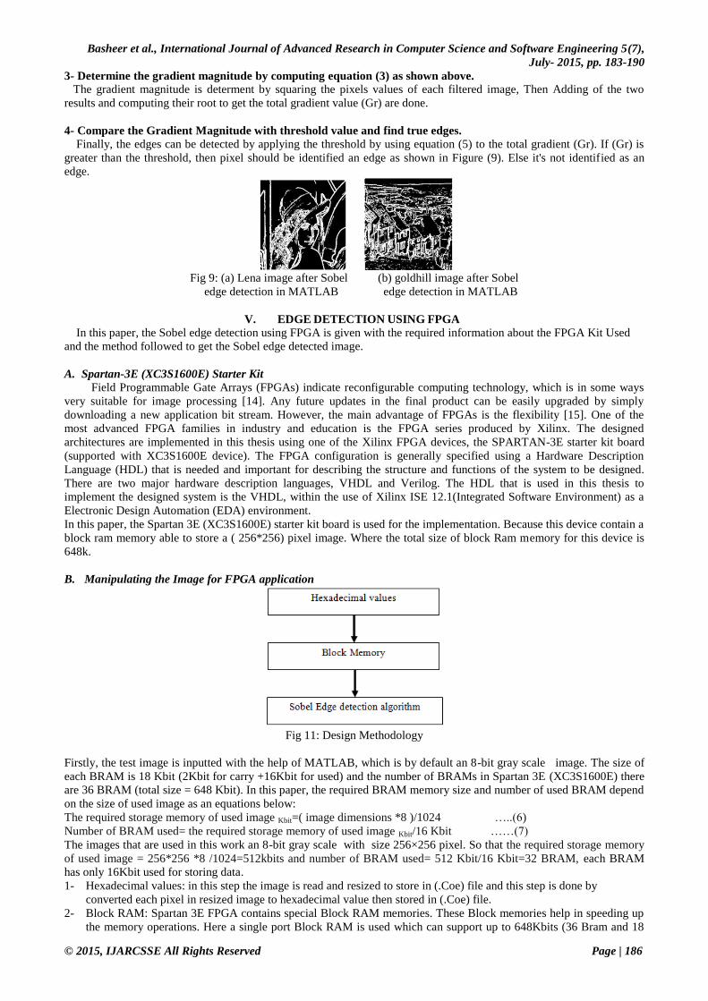
2- Block RAM: Spartan 3E FPGA contains special Block RAM memories. These Block memories help in speeding up
the memory operations. Here a single port Block RAM is used which can support up to 648Kbits (36 Bram and 18
Basheer et al., International Journal of Advanced Research in Computer Science and Software Engineering 5(7),
July- 2015, pp. 183-190
© 2015, IJARCSSE All Rights Reserved Page | 187
Kbits per each Bram) and in this work a (256*256) input image is stored in 36 Brams (512 Kbits when each Bram
have 2 Kbits for parity) and 16 Kbits that considered the true size used to store data in each Bram). The width and
depth of the design is user defined. The schematic for the block memory is shown in Fig. 12.
Fig 12 : Single Port BRAM
WE:write enable, EN:enable ,SSR: Synchronous Set/Reset, CLK:clock ADDR:Address Bus, DI:Data input Bus,
DIP:Parity data input bus.
The read and write operations of BRAM are controlled by an address counter which defines the required address and
system CLK and is rising edge triggered by default.
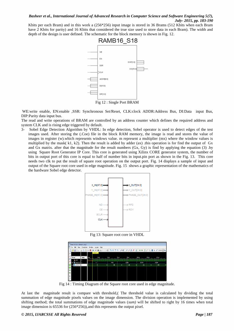
3- Sobel Edge Detection Algorithm by VHDL: In edge detection, Sobel operator is used to detect edges of the test
images used. After storing the (.Coe) file in the block RAM memory, the image is read and stores the value of
images in register (w).which represents windows value. m represent a multiplier (mx) where the window values is
multiplied by the mask( k1, k2). Then the result is added by adder (ax) .this operation is for find the output of Gx
and Gx matrix. after that the magnitude for the result numbers (Gx, Gy) is find by applying the equation (3) .by
using Square Root Generator IP Core. This core is generated using Xilinx CORE generator system, the number of
bits in output port of this core is equal to half of number bits in input.pin port as shown in the Fig. 13. This core
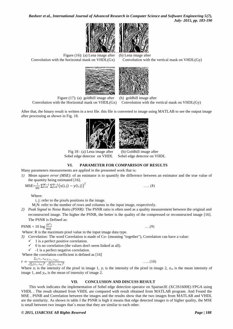
needs two clk to put the result of square root operation on the output port. Fig. 14 displays a sample of input and
output of the Square root core used in edge magnitude. Fig. 15 shows a graphic representation of the mathematics of
the hardware Sobel edge detector.
Fig 13: Square root core in VHDL
Fig 14 : Timing Diagram of the Square root core used in edge magnitude.
At last the magnitude result is compare with threshold,( The threshold value is calculated by dividing the total
summation of edge magnitude pixels values on the image dimension. The division operation is implemented by using
shifting method; the total summations of edge magnitude values (sum) will be shifted to right by 16 times when total
image dimension is 65536 for (256*256)),and this represents the output pixel.
Basheer et al., International Journal of Advanced Research in Computer Science and Software Engineering 5(7),
July- 2015, pp. 183-190
© 2015, IJARCSSE All Rights Reserved Page | 188
Figure (16): (a) Lena image after (b) Lena image after
Convolution with the horizontal mask on VHDL(Gx) Convolution with the vertical mask on VHDL(Gy)
Figure (17): (a) goldhill image after (b) goldhill image after
Convolution with the Horizontal mask on VHDL(Gx) Convolution with the vertical mask on VHDL(Gy)
After that, the binary result is written in a text file. this file is converted to image using MATLAB to see the output image
after processing as shown in Fig. 18.
Fig 18 : (a) Lena image after (b) Goldhill image after
Sobel edge detector on VHDL Sobel edge detector on VHDL
VI. PARAMETER FOR COMPARISON OF RESULTS
Many parameters measurements are applied in the presented work that is:
1) Mean square error (MSE): of an estimator is to quantify the difference between an estimator and the true value of
the quantity being estimated [16].
MSE=1
MN x i, j − y i, j
2 N−1
J=0M−1I=0 ….. (8)
Where:
i, j: refer to the pixels positions in the image.
M,N: refer to the number of rows and columns in the input image, respectively.
2) Peak Signal to Noise Ratio (PSNR): The PSNR ratio is often used as a quality measurement between the original and
reconstructed image. The higher the PSNR, the better is the quality of the compressed or reconstructed image [16].
The PSNR is Defined as:
PSNR = 10 log (R2)
MSE .…(9)
Where: R is the maximum pixel value in the input image data type.
3) Correlation: The word Correlation is made of Co- (meaning "together"), Correlation can have a value:
1 is a perfect positive correlation.
0 is no correlation (the values don't seem linked at all).
-1 is a perfect negative correlation.
Where the correlation coefficient is defined as [16]
𝑟 = 𝑥𝑖−𝑥𝑚 )( 𝑦𝑖−𝑦𝑚 )𝑖(
(𝑥𝑖−𝑥𝑚 )2𝑖 (𝑦𝑖−𝑦𝑚 )2
𝑖 ….. (10)
Where 𝑥𝑖 is the intensity of the pixel in image 1, 𝑦𝑖 is the intensity of the pixel in image 2, 𝑥𝑚 is the mean intensity of
image 1, and 𝑦𝑚 is the mean of intensity of image 2.
VII. CONCLUSION AND DISCUSS RESULT
This work indicates the implementation of Sobel edge detection operator on Spartan3E (XC3S1600E) FPGA using
VHDL . The result obtained from VHDL are compared with result obtained from MATLAB program. And Found the
MSE , PSNR and Correlation between the images and the results show that the two images from MATLAB and VHDL
are the similarity. As shown in table I the PSNR is high it means that edge detected images is of higher quality, the MSE
is small between two images that’s mean that they are similar to each other.

Basheer et al., International Journal of Advanced Research in Computer Science and Software Engineering 5(7),
July- 2015, pp. 183-190
© 2015, IJARCSSE All Rights Reserved Page | 189
Table II The difference value between images by MATLAB & VHDL using Sobel edge detector
The point that be noticed in the from the proposed work that is :
1- The size of gray scale image must be less than that size of Block RAM for this cause the size of used image in this
paper was (256*256) pixels (256*256*8/1024) that is 512 Kbits .if the size of gray scale image was (512*512 ,
1024*1024 or more than these sizes) then will need much memory size therefore the Extra RAM memory can be
used for this purpose.
2- Using the pointer to reach the positions in Bram instead of using the first in first out implementation (FIFO) reduces
the complexity of the algorithms implementation, also it reduces the size of the algorithm.
Fig 15 : Graphic representation of the Sobel edge detector on VHDL
ACKNOWLEDGEMENTS I would like to express my special appreciation and thanks to my supervisors Dr. Nasseer M.Basheer and Dr.Ashty
M.Aaref, who are they advice and guidance me during this work. Also special thanks to my family. Words cannot
express how grateful I am to my mother, and father.
Image’s type PSNR MSE correlation
Lena.bmp
(MATLAB) 72.1292 0.0040 0.9901
Lena.bmp
(FPGA(VHDL))
goldhill.tif
(MATLAB) 82.8714 3.35693359375 0.9992
goldhill.tif
(FPGA(VHDL))
Barbara.png
(MATLAB) 73.2636 0.0031 0.9928
Barbar.png
(FPGA(VHDL))
boat.png
(MATLAB) 73.3071 0.0030 0.9929
boat.png
(FPGA(VHDL))

Basheer et al., International Journal of Advanced Research in Computer Science and Software Engineering 5(7),
July- 2015, pp. 183-190
© 2015, IJARCSSE All Rights Reserved Page | 190
REFERENCES
[1] Rafael C. Gonzalez, R.E. Woods, Digital Image Processing, 3 rd edition, ISBN :013168728X
Publisher: Prentice Hall, 2007.
[2] H. Singh and Er.Tajinder Kaur, “Implementation of Various Edge Detection Techniques for Gray Scale Images
in VC++”, International Journal of Emerging Technologies in Computational and Applied Sciences (IJETCAS),
vol. 6, pp. 280-284, 2013.
[3] Lindeberg, Tony , Edge detection, in Hazewinkel, Michiel, Encyclopedia of Mathematics, Springer, ISBN 978-
1-55608-010-4, 2001.
[4] Rashmi , Mukesh Kumar, and Rohini Saxena, “Algorithm And Technique On Various Edge Detection: A
Survey “, Signal & Image Processing: An International Journal (SIPIJ), vol.. 4, pp. 65-75, June 2013.
[5] James Clerk Maxwell, Digital Image Processing Mathematical and Computational Methods, Horwood
Publishing, vol: ISBN:1-898563-49-7, 2005.
[6] Raman Maini & Dr. Himanshu Aggarwal,”Study and Comparison of Various Image Edge Detection
Techniques”, International Journal of Image Processing (IJIP), vol. 3, pp. 1-12 , 2009.
[7] Elham Jasim Mohammad,Ahmed Jassm Mohammed,Zainab Jasim Mohammad,Gaillan H.Abdullah ,Iman
Majeed Kadhim and Yasser Abd AL-Kalak Mohammed Wdaa, “Design Study Sobel Edge Detection”,
International Journal of Application or Innovation in Engineering & Management (IJAIEM),vol. 2, pp. 248-253
December 2013.
[8] Ravi S and A M Khan, “Operators Used In Edge Detection Computation: A Case Study”, International
International Journal of Applied Engineering Research, vol. 7 , 2012.
[9] Sunanda Gupta, Charu Gupta and S.K. Chakarvarti, “Image Edge Detection: A Review”, International Journal
of Advanced Research in Computer Engineering & Technology (IJARCET) , vol . 2, pp. 2278 – 1323 , July
2013.
[10] P.Sivarama Prasad and K.Srinivasa Rao, “Hardware and Software Codesign for Computer Screen Image
Processing Applications using FPGA”, IJCA Proceedings on International Conference on Recent Trends in
Information Technology and Computer Science ICRTITCS, vol. 6, pp.(6-11), February 2013.
[11] Manoj T. H and A. Santha Rubia ,” A Survey and Evaluation of Edge Detection Operators: Application to Text
Recognition”, International Journal of Computer Technology & Applications, vol. 3 4, pp. 1481-1484, 2012.
[12] Rajesh Mehra and Rupinder Verma , “Area Efficient FPGA Implementation of Sobel Edge Detector for Image
Processing Applications”, International Journal of Computer Applications, vol. 5 , pp. 7 –11, 2012 .
[13] Fisher, R.; S. W. A. Perkin, and E. Wolfart, Image Processing Learning Resources, HIPR2, Explore with JAVA,
2000.
[14] K.Sambashivudu, Md.Javeed and R.Kiran , “Implementation of 2D Non-linear Morphological Image Processing
on FPGA Based Architecture “, International Journal of Innovative Technology and Exploring Engineering
(IJITEE), vol. 3. Pp.72-75, November 2013.
[15] W. James MacLean , An Evaluation of the Suitability of FPGAs for Embedded Vision Systems, Department of
Electrical & Computer Engineering, University of Toronto, Toronto, Ontario, M5S 1A1.
[16] J. L. Rodgers .J.L and W. Alan Nicewander,” Thirteen Ways to Look at the Correlation Coefficient “, The
American Statistician, Vol. 42, No. 1, pp. 59-66 , 1988.
[17] The MathWorks, Computer Vision System Toolbox™ Reference, by MathWorks, Inc., 2013.
[18] Xilinx, Inc,”Spartan-3 generation FPGA User Guide”, UG331(v1.8) June 13, 2011.
[19] Xilinx, Inc, "Datasheet "Spartean-3E FPGA Family: Complete Data Sheet", DS312 April 18, 2008.
[20] Xilinx, "Using Block RAM in Spartan-3 FPGAs", Xilinx, Inc. XAPP463 (v1.1.2) July 23, 2003


