
XC4 DIN Medium/High-Current Connectors
1
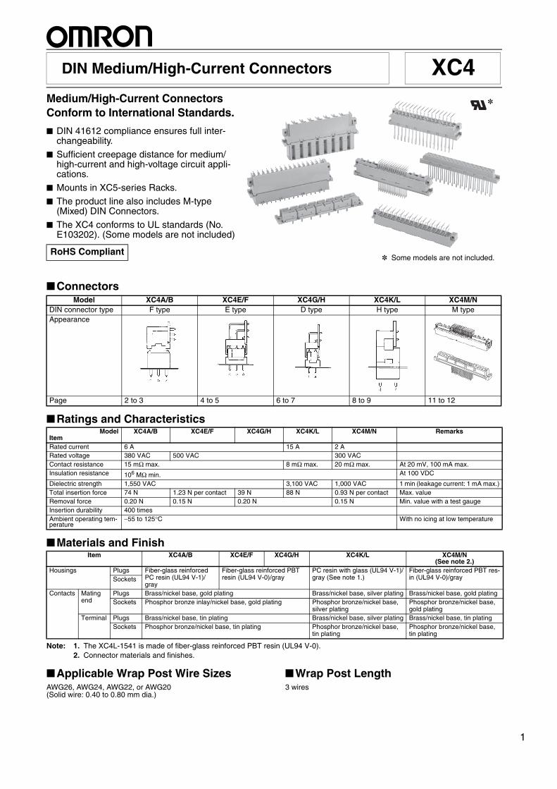
Medium/High-Current Connectors Conform to International Standards.
■ DIN 41612 compliance ensures full inter-changeability.
■ Sufficient creepage distance for medium/high-current and high-voltage circuit appli-cations.
■ Mounts in XC5-series Racks.
■ The product line also includes M-type (Mixed) DIN Connectors.
■ The XC4 conforms to UL standards (No. E103202). (Some models are not included)
■Connectors
■Ratings and Characteristics
■Materials and Finish
Note: 1. The XC4L-1541 is made of fiber-glass reinforced PBT resin (UL94 V-0).2. Connector materials and finishes.
■Applicable Wrap Post Wire SizesAWG26, AWG24, AWG22, or AWG20 (Solid wire: 0.40 to 0.80 mm dia.)
■Wrap Post Length3 wires
RoHS Compliant
Model XC4A/B XC4E/F XC4G/H XC4K/L XC4M/NDIN connector type F type E type D type H type M typeAppearance
Page 2 to 3 4 to 5 6 to 7 8 to 9 11 to 12
*
* Some models are not included.
ModelItem
XC4A/B XC4E/F XC4G/H XC4K/L XC4M/N Remarks
Rated current 6 A 15 A 2 ARated voltage 380 VAC 500 VAC 300 VACContact resistance 15 mΩ max. 8 mΩ max. 20 mΩ max. At 20 mV, 100 mA max.Insulation resistance 106 MΩ min. At 100 VDC
Dielectric strength 1,550 VAC 3,100 VAC 1,000 VAC 1 min (leakage current: 1 mA max.)Total insertion force 74 N 1.23 N per contact 39 N 88 N 0.93 N per contact Max. valueRemoval force 0.20 N 0.15 N 0.20 N 0.15 N Min. value with a test gauge Insertion durability 400 timesAmbient operating tem-perature
−55 to 125°C With no icing at low temperature
Item XC4A/B XC4E/F XC4G/H XC4K/L XC4M/N (See note 2.)
Housings Plugs Fiber-glass reinforced PC resin (UL94 V-1)/gray
Fiber-glass reinforced PBT resin (UL94 V-0)/gray
PC resin with glass (UL94 V-1)/gray (See note 1.)
Fiber-glass reinforced PBT res-in (UL94 V-0)/graySockets
Contacts Mating end
Plugs Brass/nickel base, gold plating Brass/nickel base, silver plating Brass/nickel base, gold platingSockets Phosphor bronze inlay/nickel base, gold plating Phosphor bronze/nickel base,
silver platingPhosphor bronze/nickel base, gold plating
Terminal Plugs Brass/nickel base, tin plating Brass/nickel base, silver plating Brass/nickel base, tin platingSockets Phosphor bronze/nickel base, tin plating Phosphor bronze/nickel base,
tin platingPhosphor bronze/nickel base, tin plating

2 DIN Medium/High-Current Connectors XC4
XC4A DIN F-type Plugs
■ Dimensions (unit: mm)
■ Ordering InformationAppear-
ance
No. of contacts
Terminal type Model
48 Right-angle DIP terminals XC4A-4812
Two, 2.5 dia.
Mounting holes (bottom view)
48, 1 +0.1 dia.0
Two, 2.8 dia.
XC4A-4812 (With right-angle DIP terminals)

DIN Medium/High-Current Connectors XC4 3
XC4B DIN F-type Sockets
■ Dimensions (unit: mm)
■ Ordering InformationAppear-
ance
No. of contacts
Terminal type Model
48 Straight DIP terminals XC4B-4811
Straight wrap terminals XC4B-4813
0.75 dia.
(Straight DIP terminals)
Two, 2.8 dia.
(Straight wrap terminals)
1 ´ 1
Panel dimensions
15.0 min.
Mounting holes (bottom view)
Two, 2.8 +0.1 dia.0
Two, 2.8 +0.1 dia.048, 1.0 +0.1 dia. (DIP terminals)0
48, 1.5 +0.1 dia. (Wrap terminals)0
XC4B-4813 (With straight wrap terminals)
XC4B-4811 (With straight DIP terminals)

4 DIN Medium/High-Current Connectors XC4
XC4E DIN E-type Plugs
■ Dimensions (unit: mm)
■ Ordering Information
*Has no center row (row b).
Appear-ance
No. of contacts
Terminal type Model
48 Right-angle DIP terminals XC4E-4812
32* Right-angle DIP terminals XC4E-3212
Mounting holes (bottom view)
Two, 2.8 dia.
1.0 +0.1 dia.0
Note: The mounting holes in the above diagrams are for the 48-contact Plug. The 32-contact Plug does not have the center row (C in the above diagrams).
Two, 2.5 dia.
XC4E-4812 XC4E-3212 (With right-angle DIP terminals)

DIN Medium/High-Current Connectors XC4 5
XC4F DIN E-type Sockets
■ Dimensions (unit: mm)
■ Ordering Information
*Has no center row (row b).
Appear-ance
No. of contacts
Terminal type Model
48 Straight wrap terminals XC4F-4813
32* Straight wrap terminals XC4F-3213
Mounting holes (bottom view)
Two, 2.8 dia.1.5 +0.1 dia.0
Note: The mounting holes in the above diagrams are for the 48-contact Plug. The 32-contact Plug does not have the center row (C in the above diagrams).
81
ac
e
02224262820323 61 41 24680121
95
5.08
6.311.6
20
2.84
5.08
5.08
2.9
1×1
(5.63)
15.7 13.6 3
1
90
85
76.2
XC4F-4813 XC4F-3213 (With straight wrap terminals)

6 DIN Medium/High-Current Connectors XC4
XC4G DIN D-type Plugs
■ Dimensions (unit: mm)
■ Ordering InformationAppear-
ance
No. of contacts
Terminal type Model
32 Right-angle terminals XC4G-3212
Two, 2.5 dia. 0.6×0.6
Mounting holes (bottom view)
32, 1 +0.1 dia. 0
Two, 2.8 +0.1 dia. 0
XC4G-3212 (With right-angle terminals)
DIN Medium/High-Current Connectors XC4 7
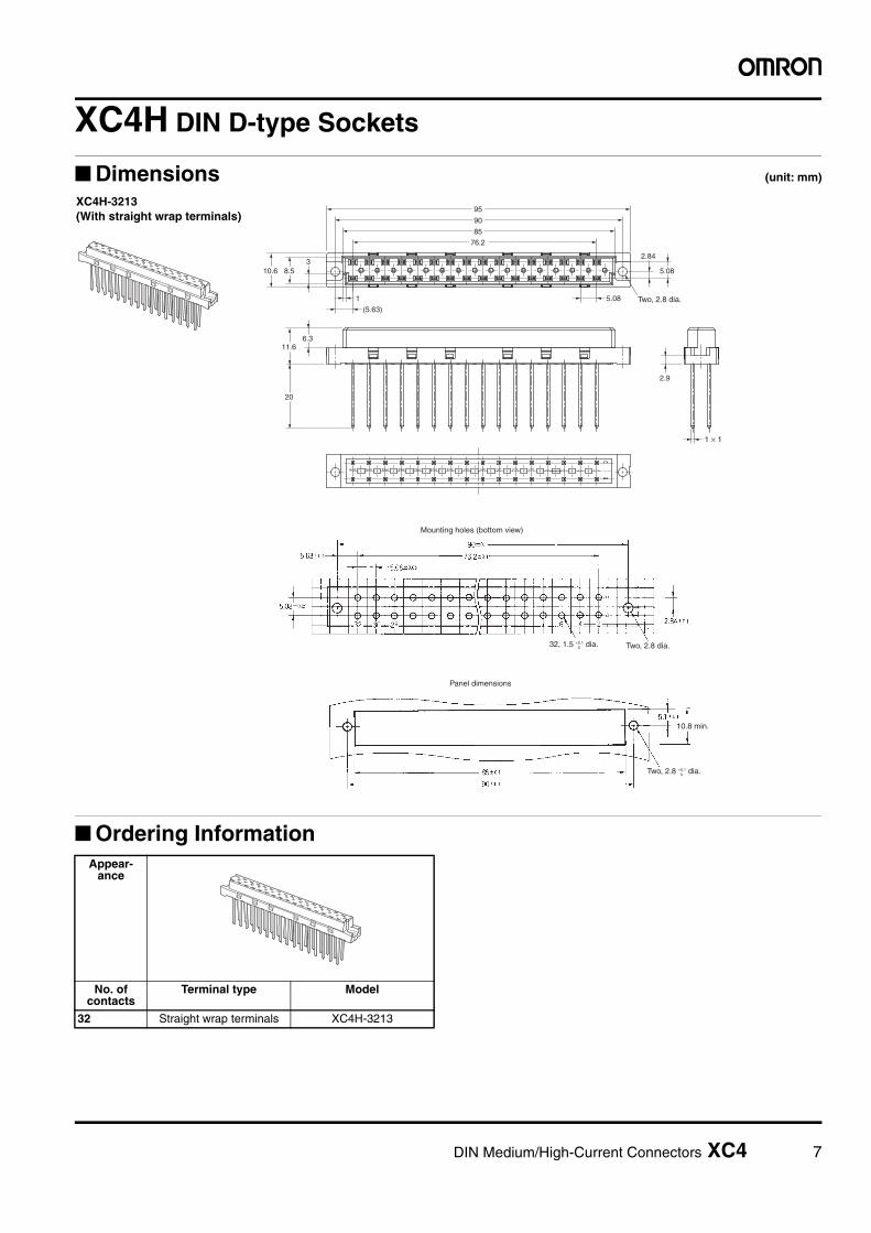
XC4H DIN D-type Sockets
■ Dimensions (unit: mm)
■ Ordering InformationAppear-
ance
No. of contacts
Terminal type Model
32 Straight wrap terminals XC4H-3213
62
a
02 81
c24688203 0122 41 21614223
95
5.08
6.311.6
20
2.84
5.08
2.9
(5.63)
10.6 8.53
1
90
85
76.2
Mounting holes (bottom view)
Two, 2.8 dia.32, 1.5 +0.1 dia.0
Panel dimensions
10.8 min.
Two, 2.8 dia.
1 × 1
Two, 2.8 +0.1 dia.0
XC4H-3213 (With straight wrap terminals)
8 DIN Medium/High-Current Connectors XC4
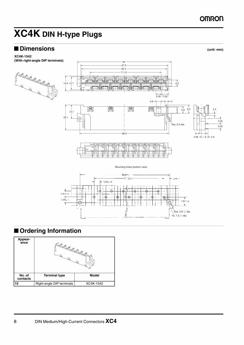
XC4K DIN H-type Plugs
■ Dimensions (unit: mm)
■ Ordering InformationAppear-
ance
No. of contacts
Terminal type Model
15 Right-angle DIP terminals XC4K-1542
Two, 2.5 dia.
Mounting holes (bottom view)
15, 1.5 +0.1 dia. 0
Two, 2.8 +0.1 dia. 0
XC4K-1542 (With right-angle DIP terminals)

DIN Medium/High-Current Connectors XC4 9
XC4L DIN H-type Sockets, Faston Tab Terminals
■ Dimensions (unit: mm)
■ Ordering Information
Note: The applicable contact is a #250 Faston receptacle.
No. of contacts
Terminal type Model
15 Faston tab terminals (See note.) XC4L-1546
Two, 2.8 dia.
Panel dimensions
15 min.
2.8 +0.1 dia. or M2.50
5.5 min.
XC4L-1546 (With Faston tab terminals)
10 DIN Medium/High-Current Connectors XC4
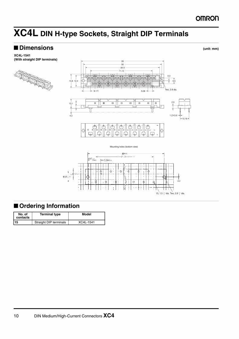
XC4L DIN H-type Sockets, Straight DIP Terminals
■ Dimensions (unit: mm)
■ Ordering InformationNo. of
contactsTerminal type Model
15 Straight DIP terminals XC4L-1541
Two, 2.8 dia.
Mounting holes (bottom view)
15, 1.5 +0.1 dia.0 Two, 2.8 +0.1 dia.0
XC4L-1541 (With straight DIP terminals)

DIN Medium/High-Current Connectors XC4 11
XC4M DIN M-type Plugs
■ Dimensions (unit: mm)
■ Ordering Information
Note: The numbers shown are the number of slots/number of signal circuit contacts.
No. of contacts (See note.)
Terminal type Model
2/78Right-angle DIP terminals
XC4M-0212
4/60 XC4M-0412
6/42 XC4M-0612
5.35 dia.
Two, 2.5 dia.4.8 dia.
Mounting holes (bottom view)
Two, 2.8 dia.
1 +0.1 dia.0
XC4M-0212 (2 slots)XC4M-0412 (4 slots)XC4M-0612 (6 slots)(With right-angle DIP terminals)
Dimensions
No. of contacts
No. of slots No. of signal circuit contacts
A (mm)
B (mm)
2/78 2 78 63.50 ---
4/60 4 60 48.26 7.62
6/42 6 42 33.02 15.24

12 DIN Medium/High-Current Connectors XC4
XC4N DIN M-type Sockets
■ Dimensions (unit: mm)
■ Ordering Information
Note: The numbers shown are the number of slots/number of signal circuit contacts.
ac
b
ac
1
1222
13
32 0131
23
b
2
02 91 61 41517181 1121
7
132.8
2.542.54
B2.541
10.5
12.6 11.66.4
8.5
3
95
5
0.3
90
85
73.66
A
Two, 2.8 dia.
0.6×0.6
Mounting holes (bottom view)
1 +0.1 dia.0
Panel dimensions
10.8 min.
12.5 min.
2.8 +0.1 dia. or M2.50
5.5 min.
Two, 2.8 +0.1 dia.06 dia.
32 31 30 3 2 1
2.54±0.05
2.54±0.05
2.54±0.05
73.66±0.1
7.62±0.1
90±0.1
A±0.1 B±0.1
0.3
XC4N-0213 (2 slots)XC4N-0413 (4 slots)XC4N-0613 (6 slots)(With straight wrap terminals)
Dimensions
No. of contacts No. of slots No. of signal circuit contacts A (mm) B (mm)2/78 2 78 63.50 ---
4/60 4 60 48.26 7.62
6/42 6 42 33.02 15.24
No. of contacts (See note.)
Terminal type Model
2/78Straight wrap terminals
XC4N-02134/60 XC4N-04136/42 XC4N-0613

DIN Medium/High-Current Connectors XC4 13
XC4W High-current Contacts for XC4M and XC4N
■ Dimensions (unit: mm)
■ Ordering Information
■ High-current Contact Characteristics
Classification Allowable current
Terminal type Model
Plugs 40 A Solder-cup terminals XC4W-0411
20 A XC4W-0211
10 A XC4W-0111
40 A Right-angle solder-DIP terminals
XC4W-0412
Receptacles 40 A Solder-cup terminals XC4W-1411
20 A XC4W-1211
10 A XC4W-1111
5.6 dia. B dia.A dia.
3.6 dia.
0.8 dia.
3.6 dia.
0.8 dia.
3.35 dia.5.6 dia. B dia.
A dia.
C7.8
11.9
22.45
XC4W-0@11Plugs with Solder-cup Terminals
XC4W-1@11Receptacle with Solder-cup Terminals
XC4W-0412Plugs with Right-angle Solder-DIP Terminals Dimensions (mm)
Model A B C
XC4W-0411 4.8 5.6 5.2
XC4W-0211 2.8 3.7 4.0
XC4W-0111 1.7 2.6 3.0
XC4W-1411 4.8 5.6 5.2
XC4W-1211 2.8 3.7 4.0
XC4W-1111 1.7 2.6 3.0
Cur
rent
(A
)
40-A contact
20-A contact
10-A contact
Temperature (°C)

14 DIN Medium/High-Current Connectors XC4
XC4W Coaxial Contacts for XC4M and XC4N
■ Dimensions (unit: mm)
■ Ordering Information
Note: The coaxial contact was designed for a 50-Ω cable, but a 75-Ωcable may be used at some frequencies.
■ Applicable Coaxial Cables
■ Coaxial Cable Characteristics
5.7 dia. A dia.
Sleeve
4.05 dia. 5.25 dia.
0.8 dia. 0.8 dia. 0.8 dia.
4.05 dia. 5.25 dia.
4.8 dia. 5.7 dia.
Sleeve
5.25 dia. 4.75 dia.
Sleeve
A dia. 5.7 dia.
XC4W-2111 (2.2 dia.)XC4W-2211 (3.2 dia.)Plug Side with Straight Cable-connecting Contact
XC4W-3111 (2.2 dia.)XC4W-3211 (3.2 dia.)Socket Side with Straight Cable-connecting Contact
XC4W-2014Plug Side with Right-angle Solder-DIP Terminals
Dimensions (mm)
Model A
XC4W-2111 2.2
XC4W-2211 3.2
XC4W-3111 2.2
XC4W-3211 3.2
XC4W-3112 2.2
XC4W-3212 3.2XC4W-3112 (2.2 dia.)XC4W-3212 (3.2 dia.)Socket Side with Right-angle Cable-connecting Contact
Contact form Sleeve diameter (mm)
Model
Plug Straight cable-connect-ing contacts (solder and crimping)
2.2 dia. XC4W-2111
3.2 dia. XC4W-2211
Right-angle solder DIP contacts
--- XC4W-2014
Socket Straight cable-connect-ing contacts (solder and crimping)
2.2 dia. XC4W-3111
3.2 dia. XC4W-3211
Right-angle cable-con-necting contacts (solder and crimping)
2.2 dia. XC4W-3112
3.2 dia. XC4W-3212
Sleeve diameter (mm)
Model Characteristic impedance
50 Ω 75 Ω2.2 dia. XC4W-2111
XC4W-3111XC4W-3112
RG178B/URG196A/U
3.2 dia. XC4W-2211XC4W-3211XC4W-3212
RG188A/URG316URG174A/U
RG179B/URG187A/U
50-Ω coaxial cable 75-Ω coaxial cable
Frequency (GHz)
Reflection factor (max.)
Frequency (MHz)
Reflection factor (max.)
Up to 1 0.05 Up to 100 0.015
1 to 4 0.07 100 to 200 0.02
4 to 10 0.10 200 to 300 0.03
DIN Medium/High-Current Connectors XC4 15
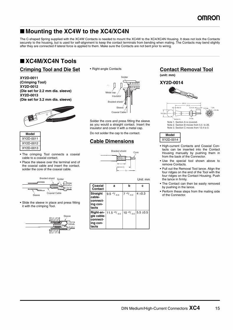
■ Mounting the XC4W to the XC4/XC4N
■ XC4M/XC4N Tools
The C-shaped Spring supplied with the XC4W Contacts is needed to mount the XC4W to the XC4/XC4N Housing. It does not lock the Contactssecurely to the housing, but is used for self-alignment to keep the contact terminals from bending when mating. The Contacts may bend slightlyafter they are connected if lateral force is applied to them. Make sure the Contacts are not bent prior to wiring.
Crimping Tool and Die Set
XY2D-0011(Crimping Tool)XY2D-0012(Die set for 2.2 mm dia. sleeve)XY2D-0013(Die set for 3.2 mm dia. sleeve)
• The crimping Tool connects a coaxialcable to a coaxial contact.
• Place the sleeve over the terminal end ofthe coaxial cable and insert the contact.solder the core of the coaxial cable.
• Slide the sleeve in place and press fittingit with the crimping Tool.
• Right-angle Contacts
Solder the core and press fitting the sleeveas you would a straight contact. Insert theinsulator and cover it with a metal cap.
Do not solder the cap to the contact.
Cable Dimensions
Unit: mm
Contact Removal Tool(unit: mm)
XY2D-0014
• High-current Contacts and Coaxial Con-tacts can be inserted into the ContactHousing manually by pushing them infrom the back of the Connector.
• Use the special tool shown above toremove Contacts.
• Pull out the Removal Tool lance. Align thefour ridges on the end of the Tool with thefour ridges on the Contact Housing. Pushthe lance in firmly.
• The Contact can then be easily removedby pushing in the lance.
• Perform these steps from the mating sideof the Connector.
Model
XY2D-0011
XY2D-0012
XY2D-0013
Braided shield Solder
SleeveCoaxial Cable
Sleeve
Coaxial Contact
a b c
Straight cable-connect-ing con-tacts
9.5 +0/−0.3 7 +0/−0.3 4 ±0.3
Right-an-gle cable-connect-ing con-tacts
11.5 +0/−0.5 10 +0/−0.5 5.5 ±0.5
Solder
Metal cap
Insulator
Braided shield
Sleeve
Coaxial Cable
Braided shieldCore
Model
XY2D-0014
(93.5)
(70.5)
B(5.5) C(13.4)11.9
19.8 dia.
14 dia.
5.5 dia. 1 dia.
4.8 dia.
Section A
Note 1. Section A is covered.Note 2. Section B moves from 5.5 to 26.Note 3. Section C moves from 13.4 to 0.

16 DIN Medium/High-Current Connectors XC4
■ Mating Diagrams (unit: mm)
■ Precautions
Correct Use
Model XC4A/B XC4E/F XC4G/HDIN
connector type
F type E type D type
Mating dia-grams
Model XC4K/L XC4M/NDIN
connector type
H type M type
Mating dia-grams
Plug XC4A-4812
Socket XC4B-4811
Plug XC4E-@@12
Socket XC4F-@@13
Plug XC4G-3212
Socket XC4H-3213
Plug XC4K-1542
Socket XC4L-1541
Plug XC4M
Socket XC4N
Automated Soldering• Use tape to mask Right-angle Connectors
before automated soldering.
• PC resin is used to make the XC4A/B,XC4K, and XC4L-1546 Housing morerugged. Only use freon TF, freon TE, oran alcohol-based cleaning solution towash the Housing, and keep washingtime as short as possible.
Automated Soldering Conditions (Jet Flow)1. Soldering temperature: 250 ±5°C2. Continuous soldering time: Within 5±1 s
Masking tape

• Application examples provided in this document are for reference only. In actual applications, confirm equipment functions and safety before using the product. • Consult your OMRON representative before using the product under conditions which are not described in the manual or applying the product to nuclear control systems, railroad
systems, aviation systems, vehicles, combustion systems, medical equipment, amusement machines, safety equipment, and other systems or equipment that may have a serious influence on lives and property if used improperly. Make sure that the ratings and performance characteristics of the product provide a margin of safety for the system or equipment, and be sure to provide the system or equipment with double safety mechanisms.
Cat. No. G055-E1-021014(0412)(O)
Note: Do not use this document to operate the Unit.
OMRON CorporationElectronic and Mechanical Components Company Contact: www.omron.com/ecb


