

International Conference on the Safety of Radioactive waste Management
SESSION 3b
Disposal of
Very Low Level Waste &
Low Level Waste

Session 3b – VLLW IAEA-CN-242
2
ORAL PRESENTATIONS
No. ID Presenter Title of Paper Page
03b – 01 65 S. Viršek
Slovenia
Safety Case for Slovenian Low & Intermediate
Level Waste (LILW) Near Surface Repository
4
03b – 02 103 M. Ranft
Germany
Morsleben Disposal Facility for Low and
Intermediate Level Radioactive Waste
8
03b – 03 98 A. Sakai
Japan
Disposal project for LLW and VLLW
Generated from Research Facilities in Japan: a
Feasibility Study for the Near Surface Disposal
of VLLW that Includes Uranium
12
03b – 04 137 J. Dose
Germany
The Asse II Mine – Tasks and Challenges 16
03b – 05 144 L. Griffault -
Sellinger
(S. Soulet)
France
The Safety Case of Andra’s Low and
Intermediate Level, Short Lived Radioactive
Waste Disposal Facility in the Aube District
(CSA)
21
03b – 06 169 A. Bagheri
Iran, Islamic
Republic of
Preliminary Post-Closure Safety Assessment
and Pre-disposal Radiomonitoring of Anarak
Near Surface Repository
26
03b – 07 190 R. Abu Eid
United States of
America
The Safety Case and the Risk-Informed
Performance-Based Approach for Management
of US Commercial Low Level Radioactive
Waste (LLRW)
30

Session 3b – VLLW IAEA-CN-242
3
POSTER PRESENTATIONS
No. ID Presenter Title of Paper Page
03b – 08 30 E.J. Seo
Korea, Republic of
Regulatory Activities and Lessons Learned in
Korea for a Low and Intermediate Level Waste
(LILW) Repository
34
03b – 09 37 D. Grigaliuniene
Lithuania
Waste Zone Conceptual Model Effect on
Predicted Radionuclide Flux from Near Surface
Repository
38
03b – 10 42 I. Kock
Germany
Multi-Phase Flow in a Complex Low Level
Waste (LLW) / Intermediate Level Waste
(ILW) Repository
42
03b – 11 43 A.M. Amin
Egypt
Safe Handling of Radioactive Animal Carcasses
Waste; Disposal Options
46
03b – 12 52 K. Tanaka
Japan
A Plan and its Safety Assessment of Very Low
Level Waste (VLLW) Disposal Site in order to
Dispose of Waste Materials Generated from
Decommissioning of Tokai Nuclear Power
Plant
51
03b – 13 120 A.H. Che
Kamaruddin
Malaysia
Site Selection Study for Radioactive Waste
Repository: Study Area of Negeri Sembilan
55
03b – 14 124 S. Sarkar
Australia
Regulatory Approach for the Assessment of the
Licence Application for Radioactive Waste
Management Facilities In Australia
62
03b – 15 157 M. Boroumandi
Iran, Islamic
Republic of
Simulation and Stability Analysis of Near
Surface Disposal Trenches of Radioactive
Waste by Using Finite Element Method
66
03b – 16 175 A. Ibrahim
Nigeria
Design of a Near Surface Disposal Facility for
Low and Intermediate Level Radioactive Waste
in Zaria, Nigeria
70
03b – 17 183 T. Von Berlepsch
Germany
The National Disposal Facility for Radioactive
Waste in Bulgaria
75

Session 3b – VLLW IAEA-CN-242
4
03b – 01 / ID 65. Disposal of Very Low Level Waste & Low Level Waste
SAFETY CASE FOR SLOVENIAN LILW NEAR-SURFACE REPOSITORY
S. Viršek, J. Špiler, T. Žagar
ARAO – Slovenian organisation for radwaste management, Ljubljana, Slovenia
E-mail contact of main author: [email protected]
Abstract. Even tough Slovenia is a small nuclear country, we have to take care of the radioactive waste
generated on its territory. In 2003, a decision was made to start the combined siting process (now popularly
called the “Nordic approach”) to find a site for the LILW repository by using an open approach and inviting
local communities to volunteer locations. Siting was finished in 2009, when the Slovenian government approved
both the site and the disposal concept that was developed during the siting.
The concept takes into consideration the properties of the site, the amount of waste and the need for modular
repository construction. The modular construction concept that was developed can be implemented in two
scenarios: a national solution for Slovenia alone or a joint solution with Croatia according to the bilateral
agreement.
The concept is called “Engineered and natural near-surface multi-barrier disposal facility”. It links together the
properties of both surface and underground repositories. The disposal silo will be constructed from the surface,
and the disposal of the final package units will also be done from the surface with the help of a portal crane.
After the silo is filled up, it will be sealed shut and placed between 55 and 15 m below the surface in a saturated
zone.
The safety of the repository has been developed based on internationally recognized LILW disposal principles.
The multi-barrier and multiple safety function principles have been introduced to the disposal concept.
All the waste meeting the waste acceptance criteria (WAC) will be packed in concrete containers and sealed
with mortar. Containers will be placed in the disposal silo and empty spaces will be filled with concrete. Once
the silo is be full it will be covered with a concrete slab and protected with a thick layer of clay from the shallow
aquifer that lies near the surface. The silo - disposal unit will be placed in layers of silt that have very low water
permeability.
In the past years, a couple of safety assessment iterations regarding the combination of the disposal concept and
the site were made, and the results show that the repository’s impact on the biosphere is negligible.
In the first part of the paper, the siting process is presented along with the site properties and the disposal
concept. The following parts include the safety assessment and the presentation of results, while the final part
provides the latest information about the project development.
Key Words: Slovenian LILW repository, near-surface disposal concept, safety case
1. Introduction
This paper presents the safety case development for the Slovenian near-surface LILW
disposal facility. Slovenia started the combined siting procedure (including not only technical
parameters but also public involvement) in 2003 to find a site for a LILW disposal facility for
the LILW generated on its territory. During the siting, the disposal concept, the safety
assessment and the preliminary design were developed, and in 2009, the Vrbina/Krško site
and the near-surface disposal concept were approved by the Slovenian government [1]. The
siting was followed by the licensing phase, which included the development of the final
design, another iteration of the safety assessment and all other necessary documentation to
obtain the construction permit.

Session 3b – VLLW IAEA-CN-242
5
2. Siting and the Vrbina/Krško site
The siting process, which started in 2003, involved all Slovenian municipalities. They were
asked to cooperate and propose areas for the construction of the LILW disposal facility.
ARAO (Slovenian organisation for radwaste management) received 8 positive replies, and
screened the proposed areas taking into account different parameters. Three most promising
sites were submitted to the Slovenian government for approval [2]. For each of them, a site
characterization program was prepared. After the approval, one of the communities with a
potential site withdrew from the procedure, and the second one proposed a new site. Because
of that work on the remaining site continued, and procedures began to evaluate the
additionally proposed site. For the first site, which was part of the process from the beginning
(approval), a feasibility study was prepared [3] in which different disposal concepts were
compared and evaluated. In 2009, the Vrbina/Krško site was approved along with the
“Engineered and natural near-surface multi-barrier disposal concept” [1].
The Vrbina/Krško site is located on gravelly lowland, approximately 300 m east from the
Krško Nuclear Power Plant (NPP) in the Krško municipality, and 2.5 km from the town of
Krško (north-west of the site). The site lies on a field, which is part of a plain along the Sava
River. The distance between the repository site and the river is approximately 700 m.
Geologically, this belongs to the Krško basin, which is a Neogene syncline that includes
Quaternary layers [4]. The entire central part of the larger Vrbina site area is covered by
Holocene Quaternary sediments from the Sava River. On the site itself, this layer is around
10 m thick. Below that lies the Miocene silt, which is the host rock formation for the disposal
facility. The thickness of this formation is more than 500 m.
In the Quaternary sediments, we can find an aquifer with a saturated thickness of 5 m on the
site and hydraulic conductivity ranges from 10-4
to 10-2
m/s. Bellow that lies a Miocene
aquiclude that comprises interchanging silty and sandy silt layers. The aquiclude was
classified according to International Association of Hydrogeologists (IAH) standards as
geological layers without significant groundwater sources and the hydraulic conductivity
ranges from 10-9
to 10-7
m/s.
FIG. 1: Schematically presented geological profile through the disposal site in the north-south
direction. (Q – Quaternary, Pl,Q – Plio Quaternary, M – Miocene)
disposal silo
disposal site
low permeable
Miocene silt

Session 3b – VLLW IAEA-CN-242
6
3. Disposal concept
The properties of the site (a shallow aquifer on the top of low permeable layers, vicinity of
the town, seismic properties of the area, the Krško NPP being jointly owned by two
companies – one from Slovenia and one from the neighbouring Croatia – meaning that the
waste from the NPP is joint responsibility) are reflected in the disposal concept that was
developed for the site [5]. It is called “Engineered and natural near-surface multi-barrier
disposal concept” and is a combination of both surface and geological disposal facilities. All
the facilities important for the nuclear safety on the site will be constructed on the
embankment (around 2 m high) that will protect against the PMF (Probable Maximum
Flood). All the waste meeting the WAC for disposal will be placed into concrete containers
with outer dimensions of 1.95 x 1.95 x 3.30 m and sealed with cement mortar. The reason for
the height (3.30 m) of the container is special over pack that is used in the NPP storage
facility. The weight of the container prepared for the disposal will be up to 40 t, and the
container will be placed by crane into the silo (99 containers in 10 layers). The inner diameter
of the silo will be around 27 m with the primary and secondary lining with a total thickness of
2.2 m. The silo will be excavated from the surface with the help of a diaphragm wall. The
empty space between the containers and the silo will be filled with concrete. Once the silo is
filled up it will be covered with a concrete slab and placed between 55 and 15 m below the
surface. The closed silo will be covered with a clay layer almost to the surface. During the
operation, a drainage system will be installed inside the silo in order to collect potential
percolating water. A building will be constructed above the silo to protect against
precipitation and other weather conditions. One disposal unit will be enough to dispose of the
Slovenian part of the waste. If Slovenia and Croatia find a common disposal solution
according to the bilateral agreement [6], an additional silo will be constructed to increase the
capacity of the repository.
FIG. 2: Slovenian LILW disposal concept

Session 3b – VLLW IAEA-CN-242
7
4. Safety assessment
The safety assessment was performed already in the siting phase to help develop the concept
suitable for the potential site. In the last iteration, the assessment [7] was used to support
licensing action and to provide the input for design optimization. It includes operational and
post-closure safety assessment, and demonstrates that the disposal facility will be able to
comply with regulatory performance objectives in Slovenia’s radiological safety regulations
[8,9]. Furthermore, sensitivity and uncertainty analyses were performed using both
deterministic and probabilistic approaches. The safety assessment has shown that the
proposed facility meets the regulatory safety criteria with a good margin in all the analyses
conducted. This conclusion is contingent on a number of basic assumptions that form the
foundation of the performed safety assessment analyses. Another purpose of safety
assessments is to provide input for the development of WAC.
5. Project status and conclusion
Slovenian LILW disposal facility project is in the first half of the licensing phase. All the
documentation needed for the environmental impact assessment is in the final preparation
stage, and procedure for obtaining the environmental protection consent will be performed in
2017. The documentation for the construction permit (final design, safety assessment, safety
report, etc.) is also under preparation and the construction permit is planned for 2018.
Slovenia now has both the site and the concept for the LILW repository while all reports
show that the impact of the planned facility on the environment will be negligible.
REFERENCES
[1] Governmental Decree on Detailed Plan of National Importance for low and
intermediate level radioactive waste repository on location Vrbina, municipality
Krško, Off. Gaz. of the RS, 114/2009.
[2] ARAO, Prefeasibility study to identify three potential sites for the LILW disposal
facility, T-2134-3/2. 2005.
[3] Acer, Feasibility study for LILW Vrbina - Krško disposal facility, rev. 1, NSRAO –
Vrb.ŠV/ŠV01/06. .
[4] Main site characterization of the Vrbina Krško site for the LILW disposal facility,
rev.1. IRGO Consulting d.o.o., GeoZS, NLZOH Maribor, Geoinženiring d.o.o., ZAG.,
2015.
[5] Draft of Vrbina Krško LILW disposal facility final design, rev. C, NRVB---5X1025.
IBE d.d, 2016.
[6] Treaty between the Gov. of the Republic of Slov. and the Gov. of the Republic of Cro.
on the regulation of the status and other legal relations regarding investment,
exploitation and decommissioning of the Krško NPP. BHRNEK, Off. Gaz. of the RS,
23/2003.
[7] Safety Analysis and Waste Acceptance Criteria Preparation for Low and Intermediate
Level Waste Repository in Slovenia – General overview of Safety Assessment Report.
ARAO (ENCO, INTERA, STUDSVIK, FACILIA, IRGO), 2012.
[8] Rules On Radioactive Waste And Spent Fuel Management (JV7). Official Gazette of
the Republic of Slovenia, No. 49/2006. Prepared in February 2011.
[9] Rules On Radiation And Nuclear Safety Factors (JV5). Official Gazette of the
Republic of Slovenia, No. 92/2009. 2011.

Session 3b – VLLW IAEA-CN-242
8
03b – 02 / ID 103. Disposal of Very Low Level Waste & Low Level Waste
MORSLEBEN DISPOSAL FACILITY FOR LOW- AND INTERMEDIATE-LEVEL
RADIOACTIVE WASTE
M. Ranft, J. Wollrath
Federal Office for Radiation Protection (BfS), Salzgitter, Germany
E-mail contact of main author: [email protected]
Abstract. The former Morsleben radioactive waste disposal facility in Saxony-Anhalt, near Helmstedt,
Germany, is located in a salt formation. The 525-m-deep Shaft Bartensleben connects 4 main mining levels and
the 520-m-deep Shaft Marie connects two main levels. Due to rock salt and potash production, many cavities
exist in this former mine with dimensions of up to 100 m in length, 30 m in width and in height. The total
volume amounts to about 8,000,000 m3 of underground cavities. By the end of the operational phase in 1998, a
total waste volume of about 37,000 m3 with a total activity of approx. 9.3•10
13 Bq (as of 2014) had been
disposed of. The licensing procedure for the closure of the ERAM was initiated in 1992 and the respective
documents were finally submitted to the licensing authority in 2009. A public hearing took place in 2011.
During the long-lasting licensing and yet not finished procedure risks have been realised which have led to
important set-backs and have caused a new management of the project.
Key Words: LLW/ILW-disposal, licensing procedure, set-backs
[1] Introduction
The former Morsleben radioactive waste disposal facility (ERAM) in Saxony-Anhalt, near
Helmstedt, Germany is located in a salt formation. The 525-m-deep Shaft Bartensleben
connects 4 main mining levels between 386 m and 596 m b.g.s. and the 520-m-deep Shaft
Marie connects two main levels. Due to rock salt and potash production, many cavities exist
in this former mine with dimensions of up to 100 m in length, 30 m in width and in height.
The total volume amounts to about 8,000,000 m3 of underground cavities.
In 1971 the operation of the ERAM for predominantly short-lived low-level radioactive waste
started. Different areas of the mine were used to dispose of the waste using different
techniques (dumping of solid waste and drums, stacking of drums and cylindrical concrete
containers, and in-situ solidification of liquid waste). In 1990 the Federal Office for Radiation
Protection (BfS) became the responsible operator of the disposal facility. By the end of the
operational phase in September 1998 a total waste volume of about 37,000 m3 with a total
activity of approx. 9.3•1013
Bq (as of 2014) had been disposed of.
[2] The Decommissioning Concept
The decommissioning of the ERAM disposal facility is based on a safety related concept for
the backfilling and sealing measures. The concept for the backfilling and sealing measures is
focused on preventing a potential brine intrusion which could not happen directly into the
disposal areas but might be possible into the other parts of the mine. Salt concrete will be
used as backfilling material to reduce the remaining volume of the mine openings to a wide
extent and to stabilise the geomechanical situation of the mine. Seals will be constructed in
the shafts and in drifts between the major disposal areas and the other openings of the mine.

Session 3b – VLLW IAEA-CN-242
9
[3] The Licensing Procedure
The licensing procedure of the closure of the ERAM has been initiated in 1992 and the
respective documents have been finally issued by BfS to the licensing authority in 2009. A
public hearing took place in 2011. Due to a recommendation of the German Nuclear Waste
Management Commission (ESK) issued in 2013 [1] the BfS has to update the Safety Case
documentation according to the development of the state-of-the-art.
In addition, during this long-lasting licensing procedure risks have been realised which have
led to important set-backs and have caused a new management of the project.
[4] Boundary Conditions for the Project Management
Primary objective in defining the goal of the project is the absolute primacy of quality (within
the meaning of fulfilling the safety licensing requirements of the necessary damage
precaution according to the state-of-the-art in science and technology). An aggravating
secondary condition is a limitation of the project duration already resulting from the
requirement of ensuring the feasibility of decommissioning. In the event that certain areas of
the ERAM are not backfilled in time, this threatens to result in the reduction and, possibly,
loss of the evidence of feasibility of decommissioning. The same goes for the avoidance of
further innovation leaps in science and technology. Here it is also presumed that the length of
the project may affect innovations in science and technology and that these may negatively
affect the decommissioning project.
According to the previous deadline, the licensed project “Decommissioning Plan” was to be
implemented from 2014 after it had been decided. On the basis of the ESK recommendations
of 31 January 2013 [1] for the further approach for the proof of post-closure safety in the
decommissioning project, the BfS developed a new time schedule. It provides for all
application documents being completed by 2028.
[5] New Requirements from Sub-Statutory Regulations and the State-of-the-Art in
Science and Technology
The Federal Ministry of the Interior (BMI) has implemented the “Safety Criteria for Disposal
in Deep Geological Formations” [2], but has not established a substitution despite the fact
that these safety criteria have been considered no longer representing the state-of-the art from
the 1990s on. Only on the basis of the “Safety Requirements Governing the Final Disposal of
Heat-Generating Radioactive Waste” from 30 September 2010 [3], which in the opinion of
the Federal Ministry for the Environment, Nature Conservation, Building and Nuclear Safety
(BMUB) only apply to HAW, did the BMUB task the ESK with defining a new state-of-the-
art in science and technology at the end of 2011. The consequences for the classification of
the documents and safety analyses are considerable, since now different protection goals
(0.1 mSv per year and 1 mSv per year) need to be taken into account for developments of the
disposal system with different probability. With regard to the protection goals, this leads to
the simplification of evidence; with respect to the classification, however, to a considerable
need for revision. This finally culminated in the ESK recommendation to submit a
comprehensive FEP list and revision of the scenario analysis based on it.
The long period covered by the plan-approval procedure in connection with the unfavourable
resource situation has resulted in changes in the state-of-the-art in science and technology
that also effect the verification management of damage precaution. So far the project could
not or only inadequately compensate these changes. The main points are:
Session 3b – VLLW IAEA-CN-242
10
Change of criteria for judging the geomechanical integrity of the salt barrier,
Necessity of addressing the concept of the “containment providing rock zone”
Approach in scenario analyses (FEP catalogue, scenario development),
2-phase-flux calculations (development of IT),
Protection goals and differentiation of disposal system development between expected
and less probable development,
Approach in geological and geotechnical modelling (3D instead of 2D),
Transport calculation taking into account groundwater density (3D instead of 2D).
[6] Risks Realised in Planning with Research Nature
One component of the verification management for safe decommissioning are technical
solutions representing a not yet tested state of technology or also state of science and
technology. These are in particular the elements of gallery seals of the decommissioning
concept. Due to existing uncertainties, the target for the design of the gallery seals was
selected very conservatively with 10-18
m2 for the permeability of the seals. Therefore, no
experiences were available for the performance of the entire decommissioning concept. This
ensured that the results of the consequence analyses were clearly below the protection goals,
despite of neglecting the processes conducive to the evidence (such as sorption).
With sealing structures erected on a trial basis, it has so far not been possible to furnish the
necessary evidence completely. On the one hand, based on the previously favoured
construction material “Sorel concret DBM2”, there is no accepted evidence for the use in
rock not capable of creep (anhydrite). Based on new findings, on the other hand, the
corrosion stability of the salt concrete seals in connection with a non-expected finding (crack
formation) having occurred in an in-situ test in rock salt, is not proven currently.
The in-situ structure, however, shows an integral permeability today which is even below the
targeted level of 10-18
m2. That means, the integral permeability of the in-situ structure
currently falls below the very conservatively selected limit. Furnishing the full evidence of
long-term operability of the sealing structures would additionally require evidence of absence
of cracks, in addition to evidence of sufficient corrosion stability. Further R&D work is
needed here. Due to the R&D character, associated risks require appropriate prevention
measures.
[7] Requirements of the Licensing Authority and its Experts Regarding Depth of
Evidence and Commitment of Examination Results
A basic challenge which is difficult to grasp consists of establishing and respecting a reliable
approach in the examination of documents relating to the procedure. Effective and detailed
legal or sub-legal specifications on this issue are at present not available. As federal
supervision, the BMUB did not make any decisions as to this matter, apart from the
recommendations of the German Commission on Radiological Protection (SSK) [4] and ESK
[1] published in 2010 and 2013 (after completion of the application documents). Nor have the
operator and the licensing authority made any explicit and sustainable agreements dealing
with this issue. Their decisions were always made with respect to specific events and were
then in most cases not permanent. On account of the lack of legal or sub-legal specification, it
is left to the licensing authority and its experts alone to determine how to “demonstrate that
the necessary precautions to prevent damage are taken”. If the licensing authority does not
make any own decisions in this regard, the freedom of design is with their expert only.

Session 3b – VLLW IAEA-CN-242
11
[8] Available Resources (Funds, Personnel, Knowledge)
Another change of the factual boundary conditions concerns the available personnel
resources. This does not only refer to changes in the availability of resources but also their
quality and effectiveness. When the Department Nuclear Waste Management (SE) of the BfS
was reorganised in 2011 (from matrix organisation to line organisation for the disposal
facility projects), it was assumed for the project ERAM that the plan-approval decision was
made soon after the public participation (2009 - 2011) and that decommissioning would start.
Therefore, the project ERAM within BfS that is oriented towards decommissioning planning
and the licensing procedure, was granted only few personnel resources. For the processing of
tasks resulting from the technical risks that had have been realised and the changed boundary
conditions (state of science and technology) there are deficiencies in resources with regard to
both extent and content. The procedure having run for a very long time meanwhile, this
situation is aggravated by the fact that knowledge is lost and evaluations change due to new
persons responsible. In the medium term, further 50 % of senior experts will leave the project
due to age-related retirements. Therefore, to implement the decommissioning project
successfully, a reorganisation of the project and additional personnel resources are necessary.
REFRENCES
[1] GERMAN NUCLEAR WASTE MANAGEMENT COMMISSION (ESK), Long-Term
Safety Case for the Morsleben Repository for Radioactive Waste (ERAM), ESK
Recommendation (2013). (in German only)
[2] FEDERAL MINISTRY OF THE INTERIOR (BMI), Safety Criteria for Disposal in Deep
Geological Formations, Rdschr. des BMI vom 20. April 1983, RS AGK 3 – 515 790/2
(1983). (in German only)
[3] FEDERAL MINISTRY FOR THE ENVIRONMENT, NATURE CONSERVATION,
BUILDING AND NUCLEAR SAFETY (BMUB), Safety Requirements Governing the
Final Disposal of Heat-Generating Radioactive Waste, http://www.bmub.bund.de
/en/topics/nuclear-safety-radiological-protection/nuclear-safety/details-nuclear-
safety/artikel/safety-requirements-governing-the-final-disposal-of-heat-generating-
radioactive-waste/?tx_ttnews[backPid]=256&cHash=bbf5f172f9319eca690ad46518411
c1c (2010).
[4] GERMAN COMMISSION ON RADIOLOGICAL PROTECTION (SSK), Radiological
Requirements for the Long-Term safety of the Morsleben Repository for Radioactive
Waste (ERAM), SSK Recommendation, http://www.ssk.de/SharedDocs/
Beratungsergebnisse_E/2010/Radiologische_Anforderungen_Morsleben_ERAM.html?nn
=2876422 (2013).

Session 3b – VLLW IAEA-CN-242
12
03b – 03 / ID 98. Disposal of Very Low Level Waste & Low Level Waste
DISPOSAL PROJECT FOR LLW AND VLLW GENERATED FROM RESEARCH
FACILITIES IN JAPAN: A FEASIBILITY STUDY FOR THE NEAR SURFACE
DISPOSAL OF VLLW THAT INCLUDES URANIUM
A. Sakai, M. Hasegawa, Y. Sakamoto, T. Nakatani
Japan Atomic Energy Agency (JAEA), Japan
E-mail contact of main author: [email protected]
Abstract. The radioactivity of uranium-bearing waste contaminated by refined uranium increases with the
production of its progeny on a long-term timescale. Therefore, the long-term safety concept of the near surface
disposal of uranium-bearing waste is very important. The Japan Atomic Energy Agency (JAEA) examines
safety of near surface disposal by controlling the average uranium radioactivity concentration in each section of
disposal facility and performing safety assessment for very conservative assumptions.
Key Words: Uranium-bearing waste, Near surface disposal, Very low level waste.
1. Objective
A near surface disposal facility for low-level radioactive waste (LLW) generated from
nuclear power plants is operating in Japan. However, the disposal of radioactive waste
generated from other nuclear facilities and radioisotope utilization facilities has not yet been
implemented. Therefore, the Japan Atomic Energy Agency (JAEA) was assigned the task of
implementing the near surface disposal of LLW and very-low-level radioactive waste
(VLLW) generated from research facilities and radioactive isotope users in Japan.
Accordingly, the JAEA has proceeded with activities focused on disposal.
The volume of VLLW is estimated to be 76000m3 according to the storage amount and
predictions of generation amount for next 50 years. VLLW will be disposed of in trench-type
facilities that do not have engineered barriers.
Approximately 25% of the volume of VLLW is uranium-bearing waste generated from
uranium utilization facilities (fuel fabrication facilities and uranium enrichment facilities,
etc.). Radioactivity of the refined uranium increases with the long-term production of its
progeny. Therefore, the calculated dose due to uranium and its progeny is estimated to reach
its peak value beyond 10,000 years. The peak dose is a relatively larger value. Determining
the probable conditions for a period of more than 10,000 years is difficult when carrying out
safety assessment of near surface disposal. This is because the surface is easily affected by
changes in the surrounding environment. Therefore, JAEA considered the safety concept for
near surface disposal of uranium-bearing waste taking into account the long-term conditions
at a disposal site.
2. Waste characteristics and disposal method
Low concentration uranium-bearing waste is estimated to account for the majority of the
expected total volume of the generated waste. Therefore, JAEA is considering to categorize
very low level uranium-bearing waste (VLL uranium-bearing waste) as VLLW and to
dispose of it in trench type disposal facilities. The assumed mean value of the radioactive
concentration of uranium in this waste is 10 Bq/g, which is ten times the clearance level for

Session 3b – VLLW IAEA-CN-242
13
radionuclides of natural origin and equal to the IAEA exemption level for U-238 in moderate
amounts of material. The maximum waste uranium concentration is assumed to be 100 Bq/g,
which is ten times the mean value.
JAEA plans to dispose of VLL uranium-bearing waste and VLLW generated from other
nuclear facilities together in the same trench. Therefore, 25% of the total volume of VLLW
will be VLL uranium-bearing waste.
3. Safety measures for disposal of VLLW including uranium
3.1. Radiation dose from uranium and its progeny at a long timeframe
Safety concept currently applied in Japan for near surface disposal is focused on short-lived
LLW. Therefore, the established safety assessment method is based on radioactive decay.
Dose criteria used in safety assessment of the disposal are 0.01 mSv/y for likely scenarios,
0.3 mSv/y for less likely scenarios, and 1 mSv/y for human intrusion scenarios and
unexpected natural event scenarios.
However, a safety assessment method for the near surface disposal of long-lived waste such
as uranium-bearing waste has not yet been determined. Therefore, the dose caused by trench
disposal of VLL uranium-bearing waste under generic conditions after a control period was
preliminarily calculated to discuss the safety of disposal. The preliminary calculation selected
exposure pathways and parameters from the representative calculation referred as basis of
regulation in Japan and the fundamental design of trench facilities.
The peak doses calculated from groundwater pathways related to utilization of contaminated
river water are sufficiently lower than 0.01 mSv/y. However, the peak dose calculated from a
residence scenario that includes the external exposure and the internal exposure from the
ingestion of crops grown in the disposal area where the waste layer and cover soil are mixed
by excavation of the site is much greater than the peak doses of groundwater pathways at a
long period of time. Figure 1 shows annual radiation dose as a function of time for residence
scenario. The peak dose of the likely condition from residence scenario is greater than 0.01
mSv/y beyond 10,000 years even though the dose is lower than 0.3 mSv/y. The inhalation
dose from radon-222 is not included in this calculation.
The scenario calculations assumed the disposal site retained its original shape before the site
was excavated. However, the disposal facility might lose its original form as a result of
erosion or disruption by natural events or human activities over a long period of time. The
precise prediction of topological change is almost impossible.
Therefore, the dose due to uranium and its progeny in the residence scenario was assessed
under very conservative assumptions where the waste layer lay below cover soil with the
thickness of 0.3 m and radioactivity of uranium and its progeny do not discharge from the
waste layer during assessment period. The thickness of cover soil is based on the usual
thickness of the additional cover soil when a residence is constructed on the ground including
waste, for example concrete, etc. The peak dose is reached at approximately 200,000 years
with a value lower than 0.3 mSv/y as shown in the conservative condition of Figure 1.

Session 3b – VLLW IAEA-CN-242
14
FIG.1 Evaluated dose due to uranium from a residence scenario that assumes a different site
situation.
IAEA [1] shows the dose criterion for a representative person resulting from a disposal
facility is 0.3mSv/y and a dose criterion for a human intrusion scenario is 1 – 20 mSv/y.
ICRP publication 122 [2] describes that exposure from non-design basis evolution in a
situation with no oversight over a long period of time in geological disposal would be treated
as an existing exposure situations. As shown in Figure 1, the calculated dose resulting from
conservatively stylized scenario for very long timeframes is lower than dose constraint or
reference level of existing exposure situation. Therefore, trench disposal of VLL uranium-
bearing waste is considered to be a feasible disposal option.
3.2. Control of the radioactive concentration of the waste layer
It is difficult to reliably predict the long-term conditions at a near surface disposal facility.
Therefore, JAEA is discussing measures to explain the long-term safety of disposal facilities.
ICRP publication 122 [2] describes principles and strategies of the protection from exposure
in situations with no oversight over long time periods of time in geological disposal. IAEA
[3] describes that material containing radionuclides of natural origin with a radioactivity
concentration of lower than 1Bq/g are managed under the existing exposure situation, and 1
Bq/g can be used as a clearance level for material containing radionuclides of natural origin.
JAEA is discussing a management method for uranium radioactivity concentrations in
trench facilities that takes into account the aforementioned information. Figure 2 shows the
management concept for a trench disposal facility. The disposal area of the trench is divided
into sections of a certain size. The arrangement of VLL uranium-bearing waste and VLLW is
controlled so that the average uranium radioactivity concentration in each section is lower
than 1 Bq/g. A section refers to a layer composed of VLL uranium-bearing waste, VLLW,
and soil fill. The surface area of a section takes into account the viewpoint of safety
assessment, for example, size of the floor space of a residence,etc.
This method assumes that future generations can choose a management method for a disposal
site based on the existing exposure situation, even in the extreme situation where a waste
layer was left on the surface without cover soil.
Average concentration of total uranium in waste is 10 Bq/g.
The composition condition is the enriched uranium containing 5 wt% U-235
Time of scenario occurrence (year)
An
nu
al R
adia
tion
Do
se (
Sv/y
)
1.E-02
1.E-01
1.E+00
1.E+01
1.E+02
1.E+03
1.E+00 1.E+01 1.E+02 1.E+03 1.E+04 1.E+05 1.E+06 1.E+07
Control period
(50 years)
Dose
constraint
Conservative condition
Likely condition

Session 3b – VLLW IAEA-CN-242
15
FIG.2 Management concept for the average uranium radioactivity concentration for each section of
waste layer.
4. Conclusion
The dose calculated from the trench disposal of VLLW that includes VLL uranium-bearing
waste is sufficiently low within several thousand years.
However, the dose increases because of production of uranium progeny for a period of
beyond 10,000 years. Measures to deal with this issue are discussed next.
First, dose assessment in the very conservative assumptions for long periods of time is
performed. The implementer confirms that the calculated dose does not exceed 0.3mSv/y,
which is the dose constraint, or 1 mSv/y which is lower reference level for existing exposure.
Second, the amount of uranium radioactivity disposed in a trench section is controlled to
reduce the average uranium concentration in the section to lower than 1 Bq/g. The result
considers the situation as an existing exposure situation. The possibility of a non-acceptable
exposure situation is reduced, even if an extreme long-term exposure situation is assumed.
These results show that it is possible to safely implement the trench disposal of VLL
uranium-bearing waste by adequately controlling the disposed radioactivity of uranium.
This feasible study is an example of safety measures for trench disposal of VLL uranium-
bearing waste by JAEA. The safety regulatory system of disposal in Japan will be discussed
in the future.
REFERENCES
[1] INTERNATIONAL ATOMIC ENERGY AGENCY, Disposal of Radioactive Waste,
Specific Safety Requirements No. SSR-5, Vienna (2011).
[2] INTERNATIONAL COMMISSION ON RADIOLOGICAL PROTECTION, ICRP,
2013. Radiological Protection in Geological Disposal of Long-Lived Solid Radioactive
Waste, ICRP Publication 122, Ann. ICRP, 42(3).
[3] INTERNATIONAL ATOMIC ENERGY AGENCY, Radiation Protection and Safety
of Radiation Sources: International Basic Safety Standards, General Safety
Requirement Part 3, No. GSR Part 3, Vienna (2014).

Session 3b – VLLW IAEA-CN-242
16
03b – 04 / ID 137. Disposal of Very Low Level Waste & Low Level Waste
THE ASSE II MINE – TASKS AND CHALLENGES
J. Dose, D. Laske, M. Mohlfeld, P.L. Wellmann
Federal Office for Radiation Protection (BfS), Salzgitter, Germany
E-mail contact of main author: [email protected]
Abstract. The Asse II salt mine near Wolfenbüttel (Germany) is an approximately 100-year-old potash and
salt mine. Salt production stopped on 31 March 1964. The decommissioned mine was bought by the federation
in 1965 and was used for the storage of low-level and intermediate-level radioactive waste. Emplacement
stopped in 1978 after the Atomic Energy Act (AtG) had been amended in 1976. Now, a nuclear law plan-
approval (licensing) procedure was required as a condition for radioactive waste disposal. The Federal Office
for Radiation Protection (BfS) was to take over the operatorship of the facility with effect of 1 January 2009.
Since 24 April 2013 the so-called “Lex Asse” (§57b AtG), the “Law on Speeding up the Retrieval of
Radioactive Waste and the Decommissioning of the Asse II Mine” has been effective. The new law is the legal
basis for the retrieval of the radioactive waste. After retrieving the radioactive waste according to § 57 b AtG,
decommissioning has to take place. Retrieving requires by law the immediate and parallel conduction of
retrieval measures.
Today, the Asse II mine faces two major problems: On the one hand, influent saline solutions enter the mine, on
the other hand the stability of the mine openings is at risk. Therefore, the BfS has developed actions for an
emergency plan for the Asse II mine. Parallel to the retrieval measures - to improve the mine’s stability and
protect the emplacement chambers as well as to minimize the consequences of potential flooding – the mine is
stabilized by backfilling remaining cavities with concrete. The emergency plan is maintained and updated on a
regular basis. For this purpose, an accompanying technical examination is carried out on the basis of
calculations; experts refer to an "analysis of consequences". With its examination, BfS aims to optimize the
developed actions for an emergency plan of the Asse II mine.
Key Words: Emergency Plan, § 57 b AtG (Atomic Energy Act), Retrieval Measures
1. Previous and Current Situation
The Asse II mine near Wolfenbüttel (Germany) was taken into operation for the production
of potash and rock salt at the beginning of the last century. The former operator used the Asse
II mine as a “research mine” for the disposal of low-level (LLW) and intermediate-level
radioactive waste (ILW)1. Between 1967 and 1987 about 47.000 m³ LLW and ILW in
different types of packaging have been stored. Today, the mine’s stability is at risk. Daily,
about 12 cubic metres of salt saturated groundwater flow into the mine. The Federal Office
for Radiation Protection (BfS) was to take over the operatorship of the facility with effect of
1 January 2009. The BfS has the task to operate the mine under nuclear law and to
decommission it without delay. Long-term safety which is required pursuant to nuclear law
can only be achieved by retrieval of the radioactive waste according to current knowledge. In
2013 the “Law on speeding up the Retrieval of Radioactive Waste and the Decommissioning
1 In Germany all kinds of radioactive waste have to be disposed of in deep geological repositories. Therefore,
there is made no difference in the characterisation between waste containing radionuclides with comparatively
short half-life. All kind of radioactive waste is divided in heat generating radioactive waste and radioactive
waste with negligible heat generation. The German classification could almost be integrated in IAEA’s waste
classification scheme [1]. In exceptional cases e.g. for the Asse II mine for historical reasons, the denomination
of low-level (LLW) and intermediate-level waste (ILW) is still used.

Session 3b – VLLW IAEA-CN-242
17
of the Asse II Mine” (“Lex Asse”, § 57 b Atomic Energy Act (AtG) [2]) becomes effective.
The law provides that, among others, no plan-approval procedure has to be carried out for
retrieval and associated tasks. According to § 57 b AtG retrieval operations must stop if their
implementation cannot be justified for radiological or other safety-related risks for the
population or the staff.
Recently the organisational structure in the area of radiation protection and final disposal of
radioactive waste in Germany was rearranged [3], [4]. The following offices resp. companies
will perform the different tasks: The former BfS will concentrate on public tasks of radiation
protection, e.g. medical research, nuclear emergency management. A new founded office
within the remit of the Federal Ministry for the Environment, Nature conservation, Building
and Nuclear Safety (BMUB), called BfE (Bundesamt für kerntechnische Entsorgungs-
sicherheit, Federal Office for the Regulation of Nuclear Waste Management) will now
regulate the site selection process and support the BMUB in its activities pertaining to the
final disposal of radioactive waste. In a second step a new founded federal company BGE
(Bundesgesellschaft für Endlagerung, Federal Company for Disposal) will take over
operational tasks from BfS as well as tasks of the Asse GmbH and DBE mbH. This includes
the BGE will take over the operational tasks for the safe decommissioning of the Asse II
mine. BGE will be also responsible for operational tasks for the site selection process,
construction and operational phase of repositories. Since the rearrangement is currently in
institutional change, we use simplified in this article “BfS” for assignment of operators task
of the Asse II mine.
2. Precaution Measures for Stabilization
Precautionary measures, parallel to all planning activities for retrieval (see Chapter 3), need
to be taken for the event of an uncontrollable inflow of water – which cannot be ruled out –
and to stabilise the mine. The precautionary measures have been pursued since 2010.
Stabilization measures are to reduce the risk that it will no longer be possible to
decommission the Asse mine in an orderly manner. Among the stabilization measures are the
so-called filling of roof clefts as well as additional measures involving the backfilling of no
longer needed cavities (blind shafts, galleries etc.) in the mine with concrete.
Stabilization of the mine and emergency preparedness are prior conditions for the retrieval of
waste. To improve the mine’s stability and protect the emplacement chambers as well as to
minimise the consequences of potential flooding – the mine is stabilised by backfilling
remaining cavities with concrete [5]. Precautionary measures include the planning,
preparation and execution of measures for filling remaining cavities nearby the ILW cavity
8a/511, sealing and stabilizing the mine on the 775-m – 700-m level, such as sealing and
installation of geotechnical structures, measures to limit the generation of gas, backfilling
remaining cavities to reduce the convergence and the possible extensions of pollutants and
provision of necessary resources for complete backfilling or the production of building
materials, see [5] for more details. More than half of backfilling of the remaining cavities to
stabilize the south shoulder is finished.
At least since 1988, saturated saline solution flows into the Asse II mine. Since the mine
openings and the overburden continue to deform, it cannot be ruled out that the inflow of
water will increase to an extent where it is no longer controllable. In this case a structured
operation of the facility can no longer be guaranteed: this is called an emergency. In this case
the emergency measures will take place. These measures include the filling of the ILW cavity

Session 3b – VLLW IAEA-CN-242
18
8a/511 with sorel concrete, the filling of the residual cavities containing LLW with brucite
cement, the backfilling and closure of the open shafts, the flooding of MgCl2 brine against the
influent unsaturated solution and if applicable under application of compressed air. Last step
is the withdrawal from the repository, see [5].
In order to manage the influent saline solutions a major part is stored intermediately in a
storage pond on the 490-m-level and pumped to the surface following radiological
examination and clearance. About 11.5 cubic metres of influent solutions are collected daily
in front of the former salt extraction chamber 3 on the 658-m-level. A minor part of solutions
(about 0.5 – 1.0 m²) is also collected on the 725-m and the 750-m-level near to the
emplacement chambers. It is either stored intermediately on site or used underground to
produce concrete. Influent solutions that were in contact with radioactive waste and are
collected on the 750-m-level must be treated as radioactive waste and be used or disposed of.
3. Planning of Retrieval
3.1.Trial Phase
To retrieve the radioactive wastes from the Asse II mine, uncertainties and gaps in knowledge
need to be eliminated for reliable planning. That is the only way to concretely approach the
technical implementation. Also necessary is the knowledge on the boundary conditions
during retrieval to provide safety conditions for the staff and general public. Significant
changes resulting from experiences gained over the past years of the trial phase led to an
optimisation of the exploration programme dealing with the emplacement chambers in 2015.
According to “Lex Asse“ a justification relating to single measures is no longer required.
Therefore the opening of the chambers and the recovering of the waste by way of trial are no
longer necessary steps in the trial phase. In order to gain relevant data for the planning of
retrieval, the exploration and testing in the trial phase at one chamber has been continued in
2016 with the drilling of a sixth borehole in order to investigate the emplacement chamber 7
at the 750-m level. In addition to emplacement chamber 7, emplacement chamber 12 on the
750-m-level will be examined in the scope of the trial phase. The “Lex Asse” facilitate
parallel planning of “Recovery Technique”, “Interim Storage Facility” and “Retrieval”
without waiting for the results from the trial phase. However, the parallel approach also
contains the risk of planning errors, if the trial phase does not lead to the anticipated results.
3.2.Recovery Technique
In order to recover radioactive waste from the emplacement chamber, special machines need
to be developed. In a first step an investigation over existing machines for recovery was
carried out. Building on that an examination regarding further development is actually done.
3.3.Design of Interim Storage Facility
A buffer storage facility, the conditioning plant and the interim storage facility are required
for repacking the recovered waste and to store it safely intermediately until it can be taken to
a repository. For these facilities the BfS needs to find a suitable location. After a balanced
assessment of the various factors, the BfS has come to the conclusion that precedence should
be given to interim storage facility sites in the near vicinity of the mine in order for them to
be directly connected to the mine premises. For implementing the site-selection procedure in
a transparent and objective procedure, the BfS defined selection criteria and first published

Session 3b – VLLW IAEA-CN-242
19
them in a discussion paper in February 2012, which forms the basis for the discussion.
Results of the discussion are issued in the Criteria Report in January 2014. Once a suitable
site for the interim storage facility has been found, planning and construction of an interim
storage facility and conditioning plant is done. The ground surface and the building ground
will significantly influence the planning works. In the event that no suitable site can be found
in the vicinity of the mine premises, it will be necessary to carry out a national search
procedure.
3.4.Retrieval: Recovery Shaft and Infrastructure
A recovery shaft needs to be built and the necessary infrastructure at the surface and
underground in the direction of the new shaft needs to be established. The infrastructure
comprises all installations (e.g. shaft tower, mine shaft buildings, laboratories, security
installations) required for the handling of the waste, from recovery to the interim storage
facility. These steps begin as soon as the geological exploration of the determined shaft site
has concluded. With the help of the drilling the geology of the rock formations will be
explored up to a depth of around 800 metres. The first exploration drilling from the surface
started in June 2013. Two exploration drillings from the 574-m-level of the Asse-II mine
towards the site of the planes new recovery shaft (shaft Asse 5) finished in 2015. A third
borehole at the 574-m-level started in July 2016. In January 2016 an exploration drilling from
the 700-m-level started and reached a length of about 250 metres in February 2016. Due to
the results of drilling (brine in borehole) more exploration drillings at the 700-m-level are
scheduled. Should the exploratory drillings show positive results, this location could be the
site for the recovery shaft over which the waste will be recovered from the Asse mine.
The planning (plan of concept) for the retrieval of all LLW and ILW radioactive waste on the
750 and 725-m-level started in spring 2015. The bidding procedure for the retrieval concept
for ILW on the 511-m-level will start in autumn 2016.
4. Analysis of Consequences and Challenging Aspects
In case of the Asse II we can state that the deep geological disposal with an insufficient or
missing safety concept adopted in the 1960s has pressed a huge cost burden on our future
generations, see also [6]. BfS and experts developed a guideline aiming at reviewing and
optimisation of precaution measures. Long-term objective of the developed guideline is
performing a post-closure safety assessment. The guideline is structured in different work
packages and is used as a “living document”. First step in this guideline is performing
shortcoming analyses. They take already into account e.g. data which are necessary to update
and the interaction of geological and hydrogeological site characterization, ground
mechanics, numerical modelling of the release and transport. First of all, requirements of
current legislation have to be respected. In a second step the safety concept, decommissioning
concept with different measures is framed and updated, containing results of the shortcoming
analyses. In further steps scenario development, concepts for numerical modelling and the
uncertainty assessment (deterministic, probabilistic) will follow. Challenging aspects of these
examinations are the enormous amounts of interactions in regard to content (analysing and
updating site conditions) and structure of the whole project. The Asse II mine is a complex
project and, generally spoken, impacts of complex projects have to be analysed from a system
perspective.

Session 3b – VLLW IAEA-CN-242
20
3. Conclusions and Outlook
This article shows tasks and challenges depending on the previous and current situation of the
Asse II mine. With its examination aiming at the analyses of consequences, BfS optimises the
developed actions for an emergency plan of the Asse II mine. BfS experience from the
conducted “analyses of consequences” for the Asse II mine emergency plan could support a
repository-operators framework for updating and improving technical examinations already
in the pre-operational and operational phase.
REFERENCES
[1] INTERNATIONAL ATOMIC ENERGY AGENCY: Classification of Radioactive
Waste, IAEA Safety Standards Series No. GSG 1, Wien, November 2009, http://www-
pub.iaea.org/MTCD/publications/PDF/Pub1419_web.pdf.
[2] ATOMIC ENERGY ACT, http://www.gesetze-im-internet.de/atg/.
[3] REPOSITORY SITE SELECTION ACT (Standortauswahlgesetz - StandAG),
http://www.gesetze-im-internet.de/standag/BJNR255310013.html.
[4] ACT REGULATING THE REORGANISATION OF TASKS AND
RESPONSIBILITIES IN THE AREA OF RADIATION PROTECTION AND FINAL
DISPOSAL (Gesetz zur Neuordnung der Organisationsstruktur im Bereich der
Endlagerung” vom 26.07.2016), http://www.gesetze-im-internet.de/aktuDienst.html.
[5] BfS: Notfallplanung für das Endlager Asse, 2010,
https://doris.bfs.de/jspui/bitstream/urn:nbn:de:0221-
2013070410956/1/BfS_2010_02_Notfallplanung_Asse.pdf .
[6] Ilg, P., Gabbert, S., Weikard, H.-P.: “Nuclear Waste Management under Approaching
Disaster. A Comparison of Decommissioning Strategies for the German Repository
Asse II”, DOI: 10.1111/risa.12648, Society for Risk Analyses, 2016.

Session 3b – VLLW IAEA-CN-242
21
03b – 05 / ID 144. Disposal of Very Low Level Waste & Low Level Waste
THE SAFETY CASE OF ANDRA’S LOW- AND INTERMEDIATE-LEVEL, SHORT-
LIVED RADIOACTIVE WASTE DISPOSAL FACILITY IN THE AUBE DISTRICT
(CSA)
S. Soulet, L. Griffault
French National Radioactive Waste Management Agency, Parc de la Croix Blanche, 92298
Châtenay-Malabry, France.
E-mail contact of main author: [email protected]
Abstract. The waste disposal facility in the Aube district (about 200 km on the east side of Paris) is designed
to receive low- and intermediate-level, short-lived radioactive waste (LILW-SL). Nonetheless, radioactive
elements with medium and long half-lives are often mixed with the low level waste, but in extremely limited
quantities and under strict control such that their presence respect long term safety criteria. The CSA was
commissioned in 1992. Once the authorized limit (one million cubic meters) has been reached, the CSA waste
disposal facility will be monitored for at least 300 years.
According to the French Act on Transparency and Security in the Nuclear Field, June 2006 [1], the licensee of a
basic nuclear installation has to carry out periodic safety review. Last safety report was issued in 2004. Next
CSA safety document was submitted to the French Nuclear Safety Authority in 2016. At the request of this
authority, the document “reexamines” whether or not the CSA conforms to regulations and reevaluates the
safety of the installation. The article aims at presenting how this “safety reexamination” was performed and
what are the major evolutions with respect to the 2004 safety report (2004 SR) [2].
The safety reexamination considers two life phases: 1) the operational phase, which extends from 1992 to about
2060 and the post closure phase, which starts at the end of the operational phase. For the operational phase,
safety demonstration relies upon the update of the risk analysis associated with the installation’s activities. The
approach allowed revisiting the dimensioning scenarios presented in the 2004 safety report. For the post-closure
phase, safety demonstration relies upon the improvements in the basic scientific understandings, the experience
gained in operating the installation, the consolidation of the safety functions, and international practices. It
allowed revisiting the scenarios taking into account an analysis of the risk and residual uncertainties at this
stage. Human intrusion scenarios will also be presented for post monitoring period.
Key Words: low- and intermediate-level, short-lived radioactive waste disposal facility in the Aube district
(CSA), 2016 safety reexamination.
1. Introduction
According to the French Act on Transparency and Security in the Nuclear Field, June 2006
[1], the licensee of a basic nuclear installation has to carry out periodic safety review. Last
CSA safety report was issued in 2004 [2] (2004 SR). Since, a draft decision text of the ASN
concerning the re-examination of safety has been issued [3]. Andra decided to take into
account this draft to define the safety re-examination goals of the CSA:
To conduct an examination of conformity of the installation.
To re-evaluate the safety of the installation for the operation and the post-closure
phases and analyse the impact of this safety re-examination on the safety reference
documents produced previously.

Session 3b – VLLW IAEA-CN-242
22
2. The CSA disposal site
The CSA is located at approximately 180 km in the southeast of Paris and in 50 km east of
the city of Troyes. It is implanted in the Aube department on the municipalities of Soulaines-
Dhuys and the Ville aux Bois. The CSA is situated in the north border of a forest, mainly
constituted by the forest of Soulaines-Dhuys (Figure 1). The site of the CSA was chosen
according to the Fundamental Safety Rule N°I.2 [6]. The choice concerned to a zone of
outcropping sedimentary rocks constituted by a semipermeable layer (Aptian white sands)
recovering a waterproof layer (the Aptian clays). The topography of the site corresponds to a
flat slope directed to the Noues d’Amance River draining all of the subterranean flows of the
zone.
Safety relies upon a confinement system isolating the waste for a sufficiently long period of time to ensure that the radioactivity in contact with humans no longer presents a health hazard due to radioactive decay. It relies upon three main barriers, the radioactive waste package, the reinforced concrete repository structure, and the geological medium. In addition, after closure a cap or cover (mainly formed of clay) will be placed over the structures and will recover the repository zone in order to limit the water infiltrations.
FIG.1. CSA LILW-SL waste disposal facility during operation (left) and after closure (schematic
illustration on the right)
3. The safety reexamination objectives of Andra’s LILW-SL waste disposal facility in
the Aube district (CSA)
According to the draft ASN decision text, the conformity examination identifies all the
regulation texts or acts applicable to the CSA, and the associated requirements in order to
check the conformity of the installation to those texts. It also identifies requirements specified
for the Important Element for the Protection (IEP) and verifies in operation documents if they
are respected. Conformity examination will also be analysed for the 2004 safety report in
order to list the differences and present the modalities and timeframe for their treatments.
The safety revaluation aims at appreciating the level of protection of the interests mentioned
in the article L 593-1 of the Environment code [4] and also:
Verifying the good application of the principle of in-depth defence (article 3.1 of the
February 7th, 2012 Order [5]), and verifying prevention measures taken for reduction
of the consequences.
Revaluating the safety margins and identifying the possible improvements (according
to the ALARA principle, better available techniques in acceptable economic
conditions ...).

Session 3b – VLLW IAEA-CN-242
23
The approach for safety reexamination during operation or post-closure phases aims at testing
the robustness of the disposal system considering extreme scenarios or situations. The post-
closure phase, consider for the safety re-examination the period of monitoring, fixed formally
by the RFS I.2 at 300 years after the closure [6], and then for the period up to 50 000 years
after the closure of the disposal (conventional choice taken to estimate the consequences of
long lived radionuclides) in coherence with the 2004 SR. The safety re-examination focused
on the following issues:
The re-evaluation of the waste inventory at closure of the disposal.
The updating of the safety functions which are applicable to the protection of the
interests in the broad sense.
The analysis of the consequence of the evolutions since the 2004 SR (evolution of the
scientific knowledge, and experience gained in operating the CSA) on risk analyses
and definition of scenarios.
The updating of the scenarios descriptions (relative to the 2004 SR) for quantitative
evaluation of the radiological and chemical toxics impacts, for both the operation and
post closure phases.
The re-evaluation of the impacts of the CSA on the protection of the interests. The
objective of this issue is to reevaluate the safety margins by considering extreme
situations in view of testing the robustness of the safety functions of the installation.
As such, these studies aim at highlighting any potential weak point during extreme
situations which would not have been considered in the design or in the previous
safety re-examinations.
4. The 2016 safety reexamination
With respect to the safety approach, the 2016 safety reexamination was performed on a list of scenarios. In application of the ASN draft decision text [2], scenarios were defined with particularly conservatives’ orientations in order to consider situations testing further the safety function of the components both for the operation and the post-closure phases.
The approach relies for both the operation and post-closure phases on a consolidated analysis of the risks and uncertainties raising the potential failures of the safety functions or dysfunctions of components assuring safety functions. They both aim at identifying events or processes which can affect one or more safety functions and consequently induce higher radiological and/or toxicological impacts on the man and its environment and thus potentially question the protection of the interests quoted in the article L. 593-1 of the code of the environment [4].
As exposed previously, safety analyses relied on the evolutions (scientific knowledge, material, disposed waste) having an impact on the safety. The scenarios from the 2004 SR have been modified according to those evolutions and re-evaluated in 2016 with additional scenarios identified on the basis of the consolidated analysis of risks and uncertainties.
Within the framework of the 2016 safety re-examination, focus was made on scenarios for which the evolutions since the 2004 SR have led to modify significantly their description (new situations at risk, acquisition of scientific knowledge, evolutions concerning the domain of the civil engineering) and their associated data (values of parameters..), and which can potentially have a different impact on the protection of the interests.
4.1.Safety reexamination during operation
Radiological evaluations are compared with protection objectives fixed for the man (worker, public or reference group) in terms of acceptable dose. Relative to the 2004 SR, for accidental situations, the radiological impact is now evaluated on the population living near the site, and it considers a more important number of waste packages.

Session 3b – VLLW IAEA-CN-242
24
From the consolidated risk analysis, the following list of scenarios has been considered for evaluation of the radiological consequences: i) Fall of waste package, and 2) Fire of waste package, iii) external event considering a plane crash, and iv) a seismic activity.
Results of the evaluations indicate that the radiological protection objectives are respected for all those scenarios although they may consider particularly penalizing hypotheses, especially for the dimensioning scenario corresponding to the fire of a transport of up to five package boxes.
4.2.Safety reexamination after closure
The evaluations are compared with objectives fixed for the public from hypothetical reference group in terms of acceptable dose. Protection objectives are defined according national and international references considering classification of scenarios and their qualitative likelihood according to the consolidated risk and uncertainty analysis. The following list of scenario has been considered:
The normal evolution scenario (NES) which represents the disposal as designed and
taking into account its evolution over time.
Altered evolution scenarios considering involuntary storage of degraded waste
package.
Altered evolution scenario considering a cumulus of events: ascending levels of the
water table, failure of the underground collector and alteration of the concrete
structures.
Altered evolution scenario considering another cumulus of events: local collapse of
the cover on one concrete repository structure, degradation of the top concrete layer of
that repository structure and a failure of the underground collector.
Altered evolution scenario considering the use of a well located at the edge of the
CSA repository during the monitoring phase by a hypothetical reference group.
This list is completed by conventional inadvertent human intrusion scenarios occurring after assumed loss of memory (taken at 300 years): i) construction of a road crossing the disposal, ii) construction of a residence on the disposal site after construction work, iii) Children games on waste rock from construction work on the disposal site and iv) use of a well located in the disposal site after the monitoring phase.
Two radiological inventories at repository closure were considered for the evaluations: the radiological inventory corresponding to the updated one from the 2004 SR based on exchanges between Andra and the waste producers and one more conservative corresponding to radiological capacities fixed by the technical prescriptions of the CSA. The safety model of the NES has been revisited upon the knowledge acquired since the 2004 SR, especially on concrete material and their evolution with time.
Results of the evaluations indicate that the radiological protection objectives are respected for all the scenarios. The well scenario after the monitoring phase appears the most penalizing scenario for the radiological impact (dose) but it is very unlikely. Radionuclides contributing to the impact are long lived radionuclides mixed with the waste but in limited quantities and strictly controlled. The results show that the presence of numerous waste packages having no or degraded performance does not question the safety of the CSA. As well, a faster degradation of other engineered components than planned does not question the safety of the CSA. In addition, results also indicate the role played by the cover in limiting infiltration of water.
REFERENCES
[1] Loi n°2006-686 du 13 juin 2006 modifiée relative à la transparence et à la sécurité en
matière nucléaire. Version consolidée au 12 Juillet 2014.

Session 3b – VLLW IAEA-CN-242
25
[2] Centre de Stockage de l’Aube (INB N°149). Rapport Définitif de Sûreté du CSFMA –
Année 2014. Rapport n°SURRPAEES040019.
[3] Lettre N°CODEP-DCN-2013-017854. Projet de décision de l’ASN relative au
réexamen de sûreté des installations nucléaires de base.
[4] Code de l’environnement. Partie Legislative. Livre V: Prévention des pollutions, des
risques et des nuisances. Titre iX: La sécurité nucléaire et les installations nucléaires de
base. Chapitre III: Installations nucléaires de base (Articles 593-1 à L593-38). (2015)
[5] Arrêté du 7 Février 2012 fixant les règles générales relatives aux installations
nucléaires de base. Ministère de l’écologie, du développement durable, des transports et
du logement (2012). Journal officiel de la République Française, n°08/02/2012.
[6] Règle N°I.2 (Révision 1) du 19 Juin 1984. Tome 1: Conception générale et principes
généraux applicables à l’ensemble de l’installation. Chapitre 2: Principes généraux de
conception et d’installation. Objet: Objectifs de sûreté et bases de conception pour les
centres de surface destinés au stockage à long terme des déchets radioactifs solides de
période courte ou moyenne et de faible ou moyenne activité massique. ASN (1984).
Publication n°RFS I.2.

Session 3b – VLLW IAEA-CN-242
26
03b – 06 / ID 169. Disposal of Very Low Level Waste & Low Level Waste
PRELIMINARY POST CLOSURE SAFETY ASSESSMENT AND PRE-DISPOSAL
RADIOMONITORING OF ANARAK NEAR SURFACE REPOSITORY
S. Hasanlou, A. Bagheri, A. Taherian, M. Boroumandi, S. Moemenzadeh, H. Mohajerani
Iran Radioactive Waste Management Co. (IRWA), Atomic Energy Organization of Iran
(AEOI), Tehran, Iran
E-mail contact of main author: [email protected]
Abstract. Anarak disposal facility is the primary low and intermediate level radioactive waste disposal site
located Anarak District, in Nain County, Isfahan Province, Iran. This paper presents the Preliminary post closure
safety assessment report and pre-disposal radiomonitoring of Anarak Near Surface Repository in order to
determine levels and variability of radiological conditions prior to operation that is needed in the licensing
process for near surface disposal repository. The Preliminary post closure safety assessment has been performed
based on ISAM methodology recommended by IAEA and AMBER Code is used for simulation of each
scenario. Three scenarios have been selected, including water erosion, bath-tubbing and human intrusion. The
water erosion considered as a design scenario as for climate condition, types of cover and trench design. 1100
years after closure of the repository and in case of water erosion scenario the maximum total dose is less than
0.2 mSv y-1
for the representative person who is living near the repository. Furthermore, the maximum dose is
caused by 241
Am that is equal to 0.15 mSv y-1
. All the results showed that estimated doses of radionuclides in
each scenario are less than dose constraint established by Iran National Regulatory Authority. Periodically about
200 samples including foodstuff, feeding material, surface and ground water, soil and sediment, airborne
particulate, radon and external radiation were gathered and analyzed. By using TLDs, The maximum average
dose equivalent value measured was approximately 100 µSv month-1
. Gross alpha and beta activities were
measured in common food commodities, including animal products, meat, grain, vegetables and feeding
materials. The ambient radon concentration in the air was found to vary from 5.55 to 18.4±0.2 Bq m-3
. The
measured gamma absorbed dose rate in the air at 1 m above the ground ranged from 0.043 to 0.075 nGy h-1
with
an overall arithmetic mean of 0.068 nGy h-1
. The activity concentration of anthropogenic (90
Sr, 137
Cs) and
natural (238
U, 232
Th, 40
K) radionuclide were determined in 78 soil and sediment samples. Tritium activity, total
alpha/beta and gamma-ray spectrometry analysis has been performed in all drinking water, surface and
groundwater samples. In general, all results showed the background level of the natural and artificial
radionuclides before any operation in Anarak near surface disposal facility.
Key Words: Anarak repository, Safety assessment scenarios, Pre-disposal, Radiomonitoring.
1. Introduction
Environmental radioactivity measurements are necessary for determining the background
radiation level due to natural radioactivity sources of terrestrial and cosmic origin [1]. Pre-
disposal radiomonitoring provides a baseline for comparison with environmental data during
the operational phase and after decommissioning the facility. Background radiation is defined
in the standard as: “radiation from cosmic sources; naturally-occurring radioactive material,
including radon (except as a decay product of source or special nuclear material); and global
fallout as it exists in the environment from the testing of nuclear explosive devices or from
past nuclear accidents such as Chernobyl that contribute to background radiation and are not
under the control of the licensee [2].
Based on the national strategy of nuclear waste management, the use of near surface
repository for the land disposal of low and intermediate level radioactive waste in Iran is
considered. In line with the internationally agreed principles of radioactive waste
management, and the national Regulations on Radioactive Waste Management prepared by

Session 3b – VLLW IAEA-CN-242
27
INRA-AEOI2, the safety of this facility needs to be ensured during all stages of its lifetime,
including the post-closure period. In this direction, the radiological environmental monitoring
and Preliminary Post Closure Safety Assessment is done during pre-operational period of the
Anarak site. Anarak disposal facility is the primary low and intermediate level radioactive
waste disposal site located Anarak city. Anarak city is situated in the central part of Iran, in
Nain County, Isfahan Province. Agricultural activities are limited because of climate
conditions, lack of water resources, and water quality. The area has very low rainfall. The
annual precipitation rate is less than 100 mm. Annual mean evaporation rate is higher than
3000 mm. Annual prevailing wind direction is from ENE and SSE. This study aims to assess
the environmental radioactivity level of the Anarak site and surrounding region prior to
operation phase. In addition Preliminary Post Closure Safety Assessment is done in various
scenarios to estimate doses of radionuclides in comparison with dose constrain established by
Iran National Regulatory Authority. The results from this study are expected to serve as
baseline data of natural radioactivity level and will be useful in assessing public doses.
2. Materials and Methods
2.1.Preliminary Post Closure Safety Assessment: Software and Scenarios
The Preliminary post closure safety assessment has been performed based on ISAM
methodology recommended by IAEA and AMBER Code is used for simulation of each
scenario. Three scenarios have been selected, including water erosion, bath-tubbing and
human intrusion. The water erosion considered as a design scenario as for climate condition,
types of cover and trench design. In this scenario the water infiltrate from upper side of the
site to the trenches and dissolves 5 percent of the waste in it, passing through unsaturated
zone close to the trench, exits to the surface and by temporary rivers reaches to the manmade
pool next to the site. These events would repeat for other 5 percent of the waste in next year
that it means 10 percent of the waste has transferred to the biosphere area. Start of this event
is after end of the passive institutional control period.
2.2.Pre-Disposal Radiomonitoring: Program and Collection of Samples
Pre-disposal radiomonitoring is done by using grid and judgmental sampling patterns.
Periodically about 200 samples including foodstuff, feeding material, surface and ground
water, soil and sediment, airborne particulate, radon and external radiation were collected and
analysed. In Table I and Table II Key radionuclides and radiomonitoring program in different
media of Anarak site is shown, respectively. The nearest population centre to this facility is
Anarak city with about 1500 population. The monitoring area spans an area of 5000 km2. All
samples were taken from various points, including: Anarak site, Anarak city, Chah-Gorbe,
Ashin, Esmailan and Piyouk villages and agricultural field-Dagh-e-Sorkh (See FIG.1).
TABLE I: KEY RADIONUCLIDES IN PRE-DISPOSAL RADIOMONITORING PROGRAM
Radiation Sources Cosmic Naturally-Occurring Radioactive Material Global Fallout
Radionuclides 3H,
7Be
238U,
226Ra,
232Th,
40K,
222Rn
137Cs,
90Sr,
3H
2 Iran Nuclear Regulatory Authority- Atomic Energy Organization of Iran

Session 3b – VLLW IAEA-CN-242
28
TABLE II: PRE-DISPOSAL RADIOMONITORING PROGRAM OF ANARAK SITE
Sampling Media Sampling
Device
Sampling
Type
Analysis
Device
Sampling
Frequency
Air Particulates
High Volume
Sampler Judgmental
Low Level
Counter Quarterly
Radon RAD7 RAD7
Direct Radiation
TLDs Grid and
Judgment
TLD Reader Quarterly
RS-230
GR-135
RS-230
GR-135 Annually
Soil - Grid and
Judgmental
HPGe
LSC Annually
Sediment - Judgmental HPGe
LSC Annually
Water
Resources
Groundwater - Judgmental HPGe
LSC
Low Level
Counter
RAD7
Semi-
annually
Surface Water - Judgmental Seasonally
Biota
Samples
Foodstuff Animal
- Judgmental HPGe
Low Level
Counter
Annually Vegetable
Feeding Material - Judgmental Annually
FIG. 1. Pre-disposal radiomonitoring area, population centers, Anarak site, seasonal surface water
streams and the elevation of the studying zone
3. Results and Discussion
3.1.Preliminary Post Closure Safety Assessment: Results for Design Scenario Assuming the representative person who is living near the repository, 1100 years after closure and in
case of water erosion scenario the maximum total dose is less than 0.2 mSv y-1
. Furthermore, the
maximum dose is caused by 241
Am that is equal to 0.15 mSv y-1
.
3.2.Pre-Disposal Radiomonitoring: Results for Representative Environmental Samples

Session 3b – VLLW IAEA-CN-242
29
Seventy-eight surface soil and sediment samples at a depth of 0–10 cm range were collected
from the sampling area on grid and judgmental basis. Mean activity concentrations of 238
U, 226
Ra, 232
Th, 40
K and 137
Cs in the soil and sediment samples were about 34.12±1.39,
34.03±0.69, 35.14±3.46, 527.09±17.72 and 5.944±1.2 Bq Kg-1
, respectively. Two methods of
active and passive were applied in order to measure external background dose rate. By using
TLDs in 25 points, the maximum average dose equivalent value measured was approximately
100 µSv month-1
. The measured gamma absorbed dose rate in the air at 1 m above the ground
ranged from 0.043 to 0.075 nGy h-1
with an overall arithmetic mean of 0.068 nGy h-1
. The
ambient radon concentration in the air was found to vary from 5.55 to 18.4±0.2 Bq m-3
. Gross
alpha and beta activities in common food commodities are shown in Table III.
Table III. Activity level in common food commodities
Sample Milk Chicken Meat Feeding Material Grain Vegetable
Gross α Activity
(Bq/L or Bq/Kg) 7.5 <MDA 8.9 22.3 1.51 6.71
Gross β Activity
(Bq/L or Bq/Kg) 255.3 146.9 92 570.7 229.7 264.4
Activity level in drinking water, surface and groundwater samples was measured. Tritium
activity in all samples was below the MDA, The geometric mean for alpha and beta
radioactivity was 0.37 and 0.42 Bq/L, respectively. In addition gamma-ray spectrometry
analysis has been performed in all samples and activity level of 238
U, 226
Ra, 232
Th, 40
K and 137
Cs was below the MDA.
4. Conclusions
The results of design scenario demonstrate that the effect of surface water erosion scenario is
acceptable. The results suggest that doses would still be well below the typical acceptance
criteria, even with cautious assumptions likely to result in over-estimates of dose in surface
water erosion scenario.
The activity concentration levels of the natural and artificial radionuclides were determined in
the all samples collected from Anarak site and surrounding area using active and passive
device. All results showed the background level of the natural and artificial radionuclides
before any operation in Anarak Near Surface Disposal Facility.
5. Acknowledgements
This study was supported by the Operation Deputy Office, Dr. Ali Maleki, Mohammad Rostamnejad,
Mohsen Asadian and Bahman Soleymanzadeh. We wish to express our warm thanks to Asghar
Mohammadi, Fariba Hadian, Hamidreza Pakouyan, Nasrin Gourani, Fatemeh-mohammad
Hosseinpour, Mohammad-ali Mohammadi, Amin Hemati, Taha Khaje-naeini, Arash Amin, Ali
Iranpour and Morteza Sabeti.
REFERENCES
[1] UNSCEAR, Ionizing Radiation: Sources and Effects of Ionizing Radiation. United
Nations Scientific Committee on the Effects of Atomic Radiation, 1993 Report to the
General Assembly, with Scientific Annexes, United Nations Sales Publication
E.94.IX.2, United Nations, New York, 1993.
[2] National Council on Radiation Protection and Measurements, Design of Effective
Radiological Effluent Monitoring and Environmental Surveillance Programs, NCRP,
Report No. 169, Vienna (2010) 10-50.

Session 3b – VLLW IAEA-CN-242
30
03b – 07 / ID 190. Disposal of Very Low Level Waste & Low Level Waste
THE SAFETY CASE AND THE RISK-INFORMED PERFORMANCE-BASED
APPROACH FOR MANAGEMENT OF US COMMERCIAL LOW-LEVEL
RADIOACTIVE WASTE (LLRW)
B. Abu-Eid, D. Esh, C. Grossman
Division of Decommissioning, Uranium Recovery and Waste Management Programs,
Office of Nuclear Materials Safety and Safeguards, US Nuclear Regulatory Commission
Washington DC 20555.
E-mail contact of main author: [email protected]
Abstract: This paper describes the US Nuclear Regulatory Commission (NRC) staff approach to safety
analysis and performance assessment for LLRW disposal. The paper presents a comparative assessment of the
approach with the IAEA safety case (e.g.; IAEA Safety Series #SSG-23; [1]) and implementation aspects being
developed in coordination with participating members, through IAEA - PRISM/PRISMA projects [2].
For the
past two decades, NRC staff developed and used comprehensive technical guidance, NUREG-1573 [3], on
performance assessment methodology for disposal of LLRW in support of 10 CFR Part 61 (NRC’s Licensing
Requirements for Land Disposal of Radioactive Waste). Currently, NRC is amending its regulations that govern
low-level radioactive waste disposal facilities to require new and revised site-specific technical analyses
(Federal Register /Vol. 80, No. 58 /Thursday, March 26, 2015; [4]). Such analyses would facilitate the
development of site-specific criteria for LLW disposal acceptance. NRC staff issued a draft guidance
(NUREG-2175; [5]) on conducting technical analyses (e.g. performance assessment, inadvertent intruder
assessment, assessment of the stability of a low-level waste disposal site, performance period analyses) to
demonstrate compliance with the performance objectives in the proposed amendment of 10 CFR Part 61. The
paper presents some aspects of NRC’s technical guidance in NUREG-1573 and the draft guidance in NUREG-
2175 and provides a brief comparison with IAEA SSG-23. In summary, we show alignment in the “Safety
Assessment” approach which is an essential constituent of the IAEA safety case. We identify overlaps with the
US NRC’s “Performance Assessment” approach, as well as with NRC’s “Risk Assessment” methodology. We
also note the important role of “Uncertainty Analysis” in the safety case and in supporting regulatory decision-
making. Although there are harmonies and many similarities, there are also some differences between the IAEA
and NRC safety case approaches. These differences are outlined and discussed briefly in the paper. Our
reviews and assessments indicate that the NRC guidance documents provide detailed technical discussion and
specific approaches to demonstrate compliance with the NRC’s proposed performance criteria required for site-
specific analysis at different analytical timeframes.
1. Introduction:
NRC regulations for shallow land disposal of LLW were promulgated in 1982 under Part 61 of
Title 10 of the U.S. Code of Federal Regulations (NRC’s Licensing Requirements for Land
Disposal of Radioactive Waste). These regulations were initially developed considering a
hypothetical reference disposal facility located within the United States. The NRC is currently
amending 10 CFR Part 61 to require new and revised site-specific technical analyses, to
permit the development of site-specific criteria for low-level radioactive waste (LLRW)
acceptance based on the results of these analyses, and to facilitate implementation and better
align the requirements with current health and safety standards. In summary, the new and
revised requirements specify: a). technical analyses for demonstrating compliance with the
public dose limits; b). technical analyses for demonstrating compliance with dose limits for
protection of the inadvertent intruder; c). requirements for development of site-specific waste
acceptance criteria; d). implementation of current dosimetry in the technical analyses; and e).

Session 3b – VLLW IAEA-CN-242
31
requirements for the “safety case” including the identification and description of defense-in-
depth protections.
2. US NRC Approaches to Risk and Performance Assessment for LLW Disposal and
Key Aspects of NRC Safety Case:
The NRC regulatory approach for ensuring the safety of LLW land disposal facilities is to
establish performance objectives that ensure protection of the general population from
releases of radioactivity (10 CFR 61.41); protection of individuals from inadvertent intrusion
(10 CFR 61.42); and stability of the disposal site after closure (10 CFR 61.44). The
performance objectives are demonstrated via technical analyses, including a performance
assessment, inadvertent intruder assessment, site stability analysis, and performance period
analysis, and compliance with technical requirements. A performance assessment (PA) is a
type of risk analysis that addresses (a) what can happen, (b) how likely it is to happen (e.g.;
including uncertainties), and (c) what are the resulting impacts (e.g.; consequences). The
requirements for a performance assessment are set forth in 10 CFR 61.13(a).
The “safety case” in 10 CFR 61.2 is defined broadly the as a “collection of information that
demonstrates the assessment of the safety of a land disposal facility.” This includes the
technical analyses discussed above as well supporting evidence and reasoning on the strength
and reliability of the technical analyses and the assumptions made therein and information on
defense-in-depth. The safety case also includes a description of the safety relevant aspects of
the site, the design of the facility, and the managerial control measures and regulatory
controls. Under 10 CFR 61.10, the information provided in a license application comprises
the key components of the safety case and must also include general and technical
information as required in the proposed rule. There are also requirements for other
information associated with institutional, financial, and monitoring activities. Thus, a safety
case for a shallow land disposal facility is envisaged by NRC to cover aspects of the
suitability of the site and the design, construction and operation of the facility, the assessment
of radiation risks and assurance of the adequacy and quality of all of the safety related work
associated with the disposal facility. The NRC staff provides detailed guidance on the
contents of a license application in NUREG-1200 [6]. The guidance in NUREG-1200 is
supplemented by detailed guidance on conducting the technical analyses in NUREG-1573
[3], which is complemented by new and revised guidance in NUREG-2175 [5]; see for
example Sections 2.0 through 6.0 of NUREG-2175. The guidance also provides acceptable
methods to identify and describe capabilities of defense-in-depth protections and develop
waste acceptance criteria.
Licensing decisions are based on whether there is reasonable assurance that the performance
objectives can be met. Defense-in-depth protections, such as siting, waste-forms,
radiological source-term, engineered features, and natural features of the disposal site,
combined with technical analyses and scientific judgment form the safety case for licensing a
LLW disposal facility. The insights derived from technical analyses include supporting
evidence and reasoning on the strength and reliability of the layers of defense relied upon in
the safety case. These insights provide input for making regulatory decisions. The licensee
must conclude that the safety case demonstrates that public health and safety will be
adequately protected from the disposal of LLW (including long-lived LLW). A clear case for
the safety of a disposal facility also serves to enhance the communication among
stakeholders.

Session 3b – VLLW IAEA-CN-242
32
The NRC staff recommends that licensees include a plain language description of the
following aspects in their safety case:
1) Strategy for Achieving Safe Disposal of Radioactive Waste: The safety strategy should
include an overall management strategy for the various activities required in the planning,
operation, and closure of a land disposal facility, including siting and characterization,
facility and disposal site design, development of the technical analyses, operations, waste
acceptance, environmental monitoring, and institutional control.
2) Description of the Disposal Site and Facility: The description of the disposal site and
facility should describe the relevant information and knowledge about the disposal system
and should provide the basis for the technical analyses.
3) Description of the Technical Analyses Demonstrating Performance Objectives: The
description of the technical analyses should summarize the performance assessment,
inadvertent intruder assessment, site stability analyses, performance period analyses, and
analyses of the protection of individuals during operations.
4) Strategy for Institutional Control of the Disposal Site: The institutional control strategy
should summarize the institutional information required by 10 CFR 61.14.
5) Description of Financial Qualifications of the Licensee: The description should
summarize the financial information required by 10 CFR 61.15.
6) Description of Other Information: Depending upon the nature of the wastes to be
disposed of and the design and proposed operation of the land disposal facility, the
description may need to summarize other information required by 10 CFR 61.16.
7) Safety Arguments: The safety arguments should draw together the key findings from the
technical analyses to highlight the main evidence, analyses, and arguments that quantify
and support the claim that the land disposal facility will ensure protection of public health
and safety.
The NRC staff envisions that the safety case for a land disposal facility would evolve over
time as new information is gained during the various phases of the facility’s development and
operation. Therefore, the NRC staff expects that the safety case will be updated as new
information that could significantly impact the safety of the facility is learned. Requirements
at 10 CFR 61.28(a) specify that the application for closure of a licensed land disposal facility
must include a final revision to the safety case that includes any updates to reflect final
inventory and closure plans. The extent of the final revisions to the safety case may vary
depending on the licensee’s operation and closure of the land disposal facility and the amount
of new information that is developed that could significantly impact safety of the facility.
3. Comparative Analysis of US NRC Approaches with IAEA-SSG-23 Safety Case:
From the IAEA perspective, the purpose of a safety case is to provide a sufficient level of
detail regarding the description of all safety relevant aspects of the site, the design of the
facility, and the managerial control measures and regulatory controls to inform the decision
whether to grant a license for the disposal of LLW and provide the public assurance that the
facility will be designed, constructed, operated, and closed safely (IAEA, [1]). NRC’s
requirements and guidance address the significant components of the safety case discussed in
IAEA SSG-23. Although not specifically addressed by the revision to 10 CFR Part 61

Session 3b – VLLW IAEA-CN-242
33
discussed herein, it is noted that communication with the public and stakeholders, as
discussed in SSG-23, is a basic practice in developing NRC regulations or key guidance
documents as well as in making licensing decisions. Further, because NRC guidance is
implementing guidance, the NRC guidance is more detailed in terms of addressing the long-
term considerations of site performance.
4. Summary& Conclusions
A comparison of NRC’s recent implementation of the safety case for LLW disposal with
IAEA’s Safety Guide SSG-23 shows harmony and consistency between the approaches.
Further, NRC’s regulatory requirements and guidance documents provide a comprehensive
analysis of safety functions and safety features of a disposal facility to satisfy the invoked
long-term site performance requirements.
REFERENCES
[1] IAEA Safety Standards Series No. SSG-23; “The Safety Case and Safety Assessment
for the Disposal of Radioactive Waste;” 2012.
[2] IAEA PRISM Project: PRISM: “Practical Illustration and Use of the Safety Case
Concept in the Management of Near-Surface Disposal;” http://www-
ns.iaea.org/projects/prism/; 2009.IAEA PRISMA Project: “Application of the Practical
Illustration and Use of the Safety Case Concept in the Management of Near-Surface
Disposal Project (PRISMA).” IAEA POC [email protected]; 2016.
[3] US NRC; “A Performance Assessment Methodology for Low-Level Radioactive Waste
Disposal Facilities: Recommendations of NRC's Performance Assessment Working
Group (NUREG-1573);” 2000.
[4] US Federal Register / Vol. 80, No. 58 / Thursday, March 26, 2015 / Proposed Rules;
16082. NUCLEAR REGULATORY COMMISSION; 10 CFR Parts 20 and 61; [NRC–
2011–0012; NRC–2015–0003]; RIN 3150–AI92; Low-Level Radioactive Waste
Disposal; Nuclear Regulatory Commission. Proposed Rule.
[5] US NRC; NUREG-2175: Guidance for Conducting Technical Analyses for 10 CFR
Part 61, Draft Report for Comment (NUREG-2175); March 2015.
[6] NRC, 1994. U.S. Nuclear Regulatory Commission, “Standard Review Plan for the
Review of a License Application for a Low-Level Radioactive Waste Disposal
Facility,” NUREG-1200, Rev. 3, Washington, DC, April 1994.

03b – 08 / ID 30. Disposal of Very Low Level Waste & Low Level Waste
REGULATORY ACTIVITIES AND LESSONS LEARNED IN KOREA FOR A LILW
REPOSITORY
E. J. Seo, M. C. Song
Korea Institute of Nuclear Safety, Daejeon, Republic of Korea
E-mail contact of main author: [email protected]
Abstract. Korea's programs to develop a low and intermediate level radioactive waste(LILW) repository were
first launched in 1986, and about twenty-year effort, a site in Gyeongju was chosen in November 2005. The
operator of disposal facility, KORAD (KOrea RADioactive waste agency) submitted an application to the
national nuclear regulatory authority for the 1st stage license, underground cavern disposal type in January 2007
and the combined construction and operating license was issued in July 2008. After the review of follow-up
actions and implementation of pre-operational inspection during construction phase, the operation of the 1st
stage facility with a capacity of 100,000 drums is approved in December 2014. During operation phase of the
facility, as the regulatory activities, the periodic inspection and the disposal inspection are implemented to
confirm whether the structure, equipment and performance of disposal facility and operational activities are in
conformity with technical standards.
Key Words: LILW repository, Safety Review, Pre-operational, Periodic and Disposal
Inspection.
1. Introduction
Korea's programs to develop a low and intermediate level radioactive waste repository were
first launched in 1986, and about twenty-year effort, a site in Gyeongju was chosen in
November 2005. The operator of disposal facility, KORAD (KOrea RADioactive waste
agency) is responsible for construction and operation of the LILW repository (Wolsong
LILW Disposal Center, WLDC), which will have a final capacity of 800,000 drums in an
area of about 2,060,000 m2 after stepwise expansion.
In January 2007, KORAD submitted an application to the national nuclear regulatory
authority for the 1st stage license, underground cavern disposal type. The professional
regulatory agency (Korea Institute of Nuclear Safety, KINS) reviewed the license documents
and the national nuclear regulatory authority issued the combined construction and operating
license in July 2008. Based on the review results, it was recommended that the applicant,
after issuance of the license, implement follow-up actions (26 items) to address issues that
require safety demonstration or further confirmation to reduce uncertainty to be identified.
After the review of follow-up actions and implementation of pre-operational inspection
during construction phase, the operation of the 1st stage facility with a capacity of 100,000
drums is approved in December 2014.
2. Stepwise development of LILW repository
The 1st stage facility is in the operational phase through a stepwise development of the
repository from site selection to construction as shown in Figure 1.

Session 3b – VLLW IAEA-CN-242
35
FIG. 1. Development of the 1st stage disposal facility in Korea.
The regulatory process for LILW repository in Korea is stepwise development as described in
Figure 2.
FIG. 2. Regulatory Process for LILW repository in Korea.
2.1.License application
The KORAD conducted site surveys and environment surveys on the finally selected site and
submitted application for Construction Permit (CP) and Operation License (OL) of a LILW
disposal facility to the Nuclear Safety and Security Commission (NSSC) based on the survey
results in January 2007. The KINS conducted a safety review of the application attached with

Session 3b – VLLW IAEA-CN-242
36
10 documents including Radiological Environmental Report (RER), Safety Analysis Report
(SAR), and Quality Assurance Program (QAP). As a result of the review, it was concluded
that the application was in compliance with the standards for permit specified in the Nuclear
Safety Act (NSA), as technical standards for location, structure, component and performance
were complied with as well as the radiological impact resulting from operation and closure of
a disposal facility was in conformity with the standards for protection of public health and the
environment as specified by Enforcement Decree of the NSA. After deliberation and
resolution, the NSSC granted the permit to the KORAD on July 2008.
Based on the review results, it was recommended that the applicant, after issuance of CP and
OL, implement follow-up actions to address issues that require safety demonstration or
further confirmation to reduce uncertainty to be identified during the period of construction
and operation, and the KINS conduct a review of the results of implementation. The
implementation and review of follow-up actions is to reduce uncertainty over safety in the
long-term and to secure the objectiveness and transparency of safety of the disposal facility
based on the safety review reflecting site characteristics obtained in the process of
construction and operation of the disposal facility. By doing so, it is ultimately possible to
develop the Safety Case for the construction stage of the disposal facility which is in line with
international requirements including the IAEA SSR-5 [1] that stipulate establishment of
Safety Case for each development stage of a disposal facility.
2.2.Construction
The construction of the disposal facility started in August 2008 and as of June 2014, most of
the construction works including excavation for construction tunnel, operation tunnel, access
shaft, unloading tunnel and disposal storage (silo) and concrete lining have been completed.
The LILW disposal facility is divided into surface and underground facilities as shown in
Figure 1. Surface facilities consist of a receipt and storage building, radioactive waste
processing buildings, service buildings and other supporting buildings. Here, radioactive
waste is received from waste generators such as NPPs and verified to be consistent with the
waste acceptance criteria. On-site treatment or conditioning is done, if necessary.
Underground facilities include construction tunnel, operation tunnel, access shaft, unloading
tunnel, and disposal silos. At first, 6 silos will be constructed approximately 80-130 meters
below sea level to dispose of approximately 100,000 waste drums.
The KORAD should undergo pre-operational inspection in accordance with the NSA during
construction phase. The purpose of the pre-operational inspection is to check prior to
operation whether the construction of a disposal facility satisfies the related design and safety
requirements. The disposal facility, etc. should be deemed to have passed the inspection when
the construction work has been progressed according to the content of a permit given under
the NSA and when the structure, equipment and performance of the disposal facility, etc. is in
conformity with the technical standard set by the NSA. The pre-operational inspection by the
KINS started in September 2008. The pre-operational inspection of the LILW disposal
facility is conducted for the purpose of confirming the appropriateness of construction and
performance and operational readiness, which is composed of 4 steps: (1) inspection on
structure, (2) inspection on system installation, (3) inspection on system performance and (4)
inspection before operation.
After the review of follow-up actions and implementation of pre-operational inspection, the
operation of the 1st stage facility is approved in December 2014.

Session 3b – VLLW IAEA-CN-242
37
2.3.Operation
The 1st disposal facility is in the operational phase and about 4,900 drums were disposed of in
the facility in September 2016. During operation phase, as the regulatory activities, the
periodic inspection and the disposal inspection are implemented.
The periodic inspection is implemented annually to confirm whether the structure, equipment
and performance of disposal facility during operational phase and whether storage, treatment
and disposal of radioactive waste are in conformity with technical standards which is
composed of 27 items including structures, radioactive waste management system. And the
disposal inspection is implemented to confirm whether the disposal of radioactive waste is in
conformity with technical standards, which is composed of 3 items: radioactive waste
management environment, radioactive waste packages and disposal environment. As a result
of the disposal inspection, when the disposal of radioactive waste is found to be in conformity
with the standards, the disposal shall be deemed to be passed.
Also, the operator of disposal facility should re-evaluate and complement, if necessary, safety
conditions of a disposal facility based on experience and data obtained from operation of a
disposal facility and results of safety assessment.
3. Concluding remarks
The 1st stage facility of the LILW repository in Korea is in the operational phase through a
stepwise development. Additionally, there are still challenges caused by the 2nd
stage
development with a capacity of 125,000 drums as a combined disposal facility: development
of underground cavern disposal (the 1st stage facility) and engineered shallow land disposal
(the 2nd
stage facility) in the same site. Especially, there will be interference of pathways,
complex radiation exposure etc. The KORAD submitted application for CP and OL of the 2nd
facility in December 2015 and the safety review is underway by KINS.
The establishment of Safety Case at any step in the development of disposal system including
the 2nd
stage facility shall be improved reflecting the experiences from the 1st stage
development.
REFERENCES
[1] INTERNATIONAL ATOMIC ENERGY AGENCY, Disposal of Radioactive Waste,
IAEA-SSR-5, Vienna (2011).
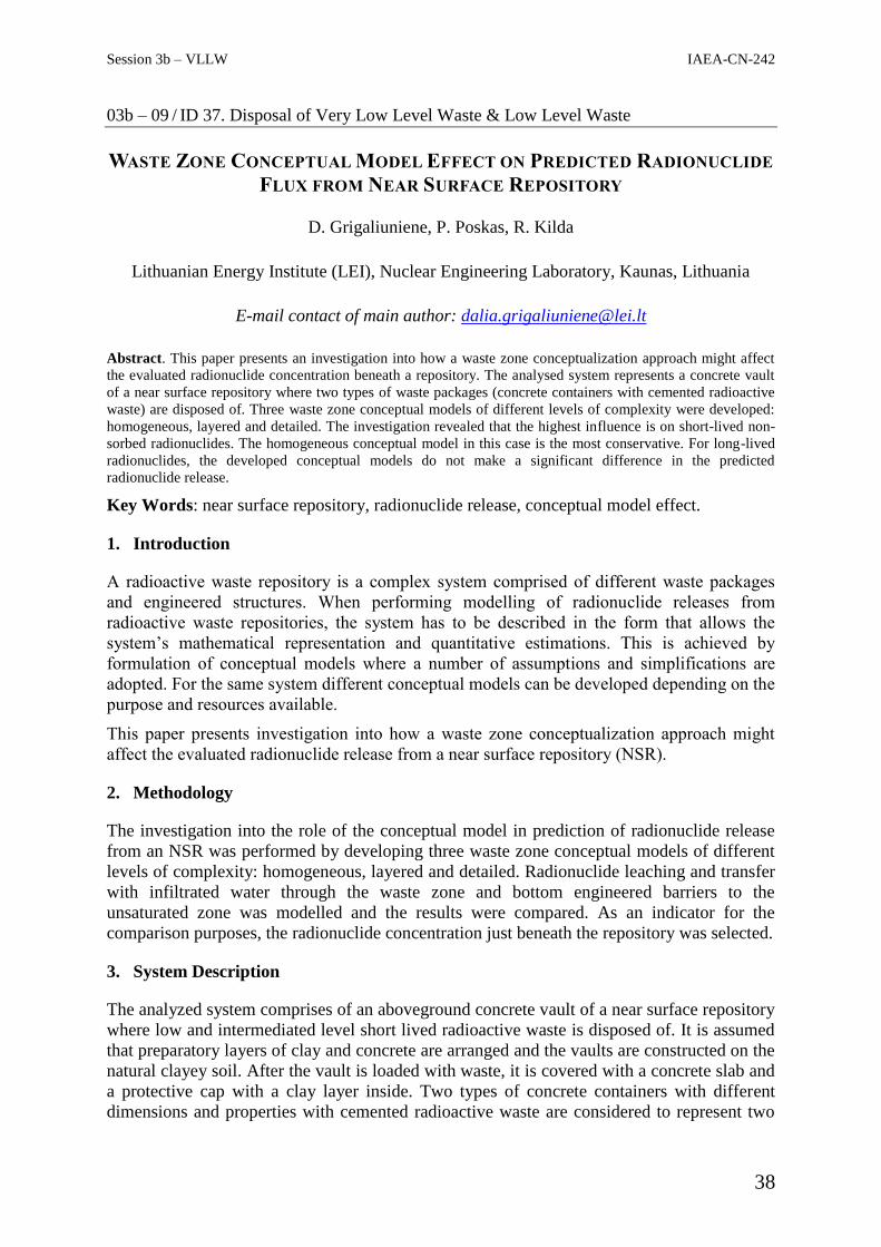
Session 3b – VLLW IAEA-CN-242
38
03b – 09 / ID 37. Disposal of Very Low Level Waste & Low Level Waste
WASTE ZONE CONCEPTUAL MODEL EFFECT ON PREDICTED RADIONUCLIDE
FLUX FROM NEAR SURFACE REPOSITORY
D. Grigaliuniene, P. Poskas, R. Kilda
Lithuanian Energy Institute (LEI), Nuclear Engineering Laboratory, Kaunas, Lithuania
E-mail contact of main author: [email protected]
Abstract. This paper presents an investigation into how a waste zone conceptualization approach might affect
the evaluated radionuclide concentration beneath a repository. The analysed system represents a concrete vault
of a near surface repository where two types of waste packages (concrete containers with cemented radioactive
waste) are disposed of. Three waste zone conceptual models of different levels of complexity were developed:
homogeneous, layered and detailed. The investigation revealed that the highest influence is on short-lived non-
sorbed radionuclides. The homogeneous conceptual model in this case is the most conservative. For long-lived
radionuclides, the developed conceptual models do not make a significant difference in the predicted
radionuclide release.
Key Words: near surface repository, radionuclide release, conceptual model effect.
1. Introduction
A radioactive waste repository is a complex system comprised of different waste packages
and engineered structures. When performing modelling of radionuclide releases from
radioactive waste repositories, the system has to be described in the form that allows the
system’s mathematical representation and quantitative estimations. This is achieved by
formulation of conceptual models where a number of assumptions and simplifications are
adopted. For the same system different conceptual models can be developed depending on the
purpose and resources available.
This paper presents investigation into how a waste zone conceptualization approach might
affect the evaluated radionuclide release from a near surface repository (NSR).
2. Methodology
The investigation into the role of the conceptual model in prediction of radionuclide release
from an NSR was performed by developing three waste zone conceptual models of different
levels of complexity: homogeneous, layered and detailed. Radionuclide leaching and transfer
with infiltrated water through the waste zone and bottom engineered barriers to the
unsaturated zone was modelled and the results were compared. As an indicator for the
comparison purposes, the radionuclide concentration just beneath the repository was selected.
3. System Description
The analyzed system comprises of an aboveground concrete vault of a near surface repository
where low and intermediated level short lived radioactive waste is disposed of. It is assumed
that preparatory layers of clay and concrete are arranged and the vaults are constructed on the
natural clayey soil. After the vault is loaded with waste, it is covered with a concrete slab and
a protective cap with a clay layer inside. Two types of concrete containers with different
dimensions and properties with cemented radioactive waste are considered to represent two

Session 3b – VLLW IAEA-CN-242
39
different waste streams. It is assumed that the waste packages are arranged in four layers and
backfilled with cement-based material. The first and the third layers are formed of one type of
the waste packages while the other type of the waste packages is placed in the second and the
fourth layers. Schematic representation of the analysed system is presented in FIG.1.
FIG. 1. Fragment of the cross section of the disposal vault: 1 – top engineered barriers, 2 – waste
packages, 3 – backfill, 4 – bottom engineered barriers, 5 – natural soil.
A number of radionuclides with different physical (half-life) and chemical (retention)
properties were considered in the analysis: short-lived non-sorbed (H-3), short-lived sorbed
(Sr-90, Cs-137), long-lived non-sorbed (C-14 organic), long-lived weakly-sorbed (Cl-36, I-
129) and long-lived strongly-sorbed (C-14 inorganic, Tc-99, Pu-239). Activity of each
radionuclide in the vault is set as 1 TBq.
Water flow rate through the vault depends on the performance of the engineered barriers. It is
assumed that the engineered barriers will be intact and minimize the infiltration of water into
the NSR within the period of 100 years (this corresponds to the institutional control period).
Then sudden degradation of the concrete barriers is assumed. After degradation of the
concrete, the most resistive barrier is the cap. Thus, amount of water entering the vaults
gradually increases following the degradation of the cap until a natural infiltration rate is
reached.
4. Conceptual Models
Homogeneous model. In the homogeneous model, the waste zone is modelled as the
homogeneous waste form-container-backfill mixture in a vault. The properties of the
homogenized waste zone were defined taking into account the properties of the waste
packages and backfill, and their occupied volume in the vault. It was assumed that the
radionuclides are homogeneously distributed in the waste zone.
Layered model. In the layered model, the waste zone is divided into layers to represent the
structure of the waste packages arrangement in the vault. However, the homogenization in
this case is not fully avoided as the layers with waste packages are represented as
homogeneous mixture of the waste form-container-backfill between containers in the same
layer. It was assumed that the radionuclides are homogeneously distributed in the layers with
the waste packages.
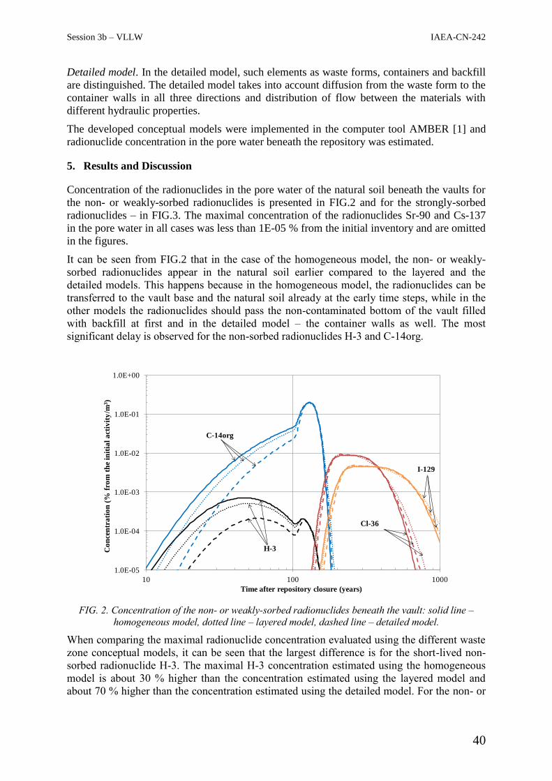
Session 3b – VLLW IAEA-CN-242
40
Detailed model. In the detailed model, such elements as waste forms, containers and backfill
are distinguished. The detailed model takes into account diffusion from the waste form to the
container walls in all three directions and distribution of flow between the materials with
different hydraulic properties.
The developed conceptual models were implemented in the computer tool AMBER [1] and
radionuclide concentration in the pore water beneath the repository was estimated.
5. Results and Discussion
Concentration of the radionuclides in the pore water of the natural soil beneath the vaults for
the non- or weakly-sorbed radionuclides is presented in FIG.2 and for the strongly-sorbed
radionuclides – in FIG.3. The maximal concentration of the radionuclides Sr-90 and Cs-137
in the pore water in all cases was less than 1E-05 % from the initial inventory and are omitted
in the figures.
It can be seen from FIG.2 that in the case of the homogeneous model, the non- or weakly-
sorbed radionuclides appear in the natural soil earlier compared to the layered and the
detailed models. This happens because in the homogeneous model, the radionuclides can be
transferred to the vault base and the natural soil already at the early time steps, while in the
other models the radionuclides should pass the non-contaminated bottom of the vault filled
with backfill at first and in the detailed model – the container walls as well. The most
significant delay is observed for the non-sorbed radionuclides H-3 and C-14org.
FIG. 2. Concentration of the non- or weakly-sorbed radionuclides beneath the vault: solid line –
homogeneous model, dotted line – layered model, dashed line – detailed model.
When comparing the maximal radionuclide concentration evaluated using the different waste
zone conceptual models, it can be seen that the largest difference is for the short-lived non-
sorbed radionuclide H-3. The maximal H-3 concentration estimated using the homogeneous
model is about 30 % higher than the concentration estimated using the layered model and
about 70 % higher than the concentration estimated using the detailed model. For the non- or
1.0E-05
1.0E-04
1.0E-03
1.0E-02
1.0E-01
1.0E+00
10 100 1000
Co
nce
ntr
ati
on
(%
fro
m t
he
init
ial
act
ivit
y/m
3)
Time after repository closure (years)
C-14org
Cl-36
H-3
I-129

Session 3b – VLLW IAEA-CN-242
41
weakly-sorbed long-lived radionuclides, the difference in the maximal concentration
estimated using different models is less than 10 %.
Similar results are obtained for the strongly-sorbed radionuclides, see FIG.3. In this case the
earliest appearance of the radionuclides in the natural soil is also observed for the
homogeneous model and selection of the waste zone conceptual model gives a rather small
difference (less than 10 %) in the evaluated maximal radionuclide concentration beneath the
vault.
FIG. 3. Concentration of the strongly-sorbed radionuclides beneath the vault: solid line –
homogeneous model, dotted line – layered model, dashed line – detailed model.
When analysing the obtained results, the assumptions related to the degradation of the
engineered barriers should be also pointed out. In the modelling it was assumed that the
concrete barriers remain intact for 100 y and then sudden degradation of the concrete occurs.
After the concrete degradation, the properties of the waste zone components are almost the
same. H-3 is the only radionuclide analyzed with the maximal concentration in the soil
beneath the vault reached before degradation of the barriers. For other radionuclides the
maximal concentration in the soil is reached after the concrete degradation, and the level of
detail of the conceptual model plays a minor role.
6. Conclusions
The investigation into how the developed waste zone conceptual model affects the predicted
radionuclide concentration beneath the repository revealed that the highest influence is for the
short-lived non-sorbed radionuclides. The homogeneous conceptual model in this case is the
most conservative. For the long-lived radionuclides, the developed conceptual models do not
make a significant difference in the predicted maximal radionuclide concentration.
REFERENCES
[1] QUANTISCI AND QUINTESSA. AMBER 4.4 Reference Guide, Version 1.0, Enviros
QuantiSci, Culham (2002).
1.0E-08
1.0E-07
1.0E-06
1.0E-05
1.0E-04
100 1000 10000 100000
Co
nce
ntr
ati
on
(%
fro
m t
he
init
ial
act
ivit
y/m
3)
Time after repository closure (years)
C-14inorg
Pu-239
Tc-99

Session 3b – VLLW IAEA-CN-242
42
03b – 10 / ID 42. Disposal of Very Low Level Waste & Low Level Waste
MULTI-PHASE FLOW IN A COMPLEX LLW/ILW REPOSITORY
I. Kock, G. Frieling, M. Navarro, S. Hotzel
Gesellschaft für Anlagen- und Reaktorsicherheit (GRS) gGmbH, Köln, Germany
E-mail contact of main author: [email protected]
Abstract. Our R&D project, financed by the German Federal Ministry for the Environment, Nature
Conservation, Building and Reactor Safety, was designed to assess to which degree the choice of the physical
model (single phase vs. multi-phase flow) and the choice of the geometrical model (simple vs. complex) is
significant for the simulation results of the repository system regarding
i. Fluid flow (e. g. gas and liquid fluxes),
ii. Fluid and radionuclide mixing (e. g. dilution),
iii. Radionuclide transport inside and potential escape out of the repository.
Instead of using a generic repository model, an existing repository for LLW/ILW, the “Endlager für radioaktive
Abfälle Morsleben (ERAM)” was chosen as the ideal example to examine these issues, in particular since our
project results could be compared to existing calculations.
The code we used for our calculations is a version of TOUGH2 enhanced by various processes (e. g. host rock
convergence, etc.) relevant in a rock salt based nuclear waste repository. For all enhancements strict quality
assurance procedures were carried out.
Unsurprisingly, fluid flow patterns differ strongly between each of the model whereas the difference in 14
C
release between the models is not quite as strong. Results indicate that especially initial two-phase fluid flow
parameters, e. g. the initial liquid saturation of the seals, are of importance to the repository system.
Key Words: Two-Phase Flow, ERAM, TOUGH2
1. Introduction
In recent years, two-phase fluid flow calculations have become common regarding the
disposal of radioactive waste in various host rocks [1]. The generation of gas and its
consequential effects e. g. the rise in pressure and the transport of contaminants out of the
repository are potential safety relevant processes.
Recently, we conducted a preliminary safety analysis [2] where numerical calculations
regarding the two-phase flow of gas and brine were carried out on repository scale [3,4]. For
the simulations, the code TOUGH2 [5], modified by GRS with several extensions relevant to
processes in a nuclear waste repository [6], was used. Beyond conducting a successful
analysis, many issues had been identified which suggest further development of the approach.
Especially the question if a more complex model layout is possible and applicable for a
complex mine was of interest. Moreover various extensions to the software, most notably
limiting gas generation to actual water content, were considered essential.
Consequently, our R&D project, financed by the German Federal Ministry for the
Environment, Nature Conservation, Building and Reactor Safety, was designed to assess to
which degree the choice of the physical model (single phase vs. multi-phase flow) and the
choice of the geometrical model (simple vs. complex) is significant for the simulation results
of the repository system regarding
i. Fluid flow (e. g. gas and liquid fluxes),
ii. Fluid and radionuclide mixing (e. g. dilution),
Session 3b – VLLW IAEA-CN-242
43
iii. Radionuclide transport inside and potential escape out of the repository.
We decided to select the LLW/ILW repository “Endlager für radioaktive Abfälle Morsleben
(ERAM)” as our case study. Currently, the application for decommissioning (e. g. [7]) is
being reviewed for this repository. For the application numerous calculations regarding the
long term safety had been conducted [8,9]. The fluid-flow calculations are single phase, using
a simplified, single floor geometrical model of the former salt mine’s multi floored structure.
FIG. 1. Geometric Structure of the ERAM (southern part Bartensleben). Based on [10].
2. Models, Simulations and Code
Our simulations are based on a modified version of TOUGH2 [6]. Currently, all
modifications are bundled in a quality-controlled (QC) [11] version now called TOUGH2-
GRS Version 01 [12]. For all calculations the same QC-version of TOUGH2 was used.
TOUGH2 is a two-phase fluid flow simulator, where in our case a gaseous phase and a liquid
phase are considered. Radionuclide transport in our simulations is limited to nuclides with a
half-life greater than 500 a. Both nuclides from decay chains and nuclides with induced
radioactivity are considered. Altogether 35 nuclides were taken into account where only 14
C
was relevant for transport via the gas phase (in CH4 or CO2).
To test for the effects of model complexity we build three meshes, all in 3D. The first mesh,
the so called “basic mesh” is fully based on the geometrical model of [8,9] and consists of
~10 blocks with a large volume and little space discretization. The repository areas with
highest activity (repository areas West, South and East) are sealed by geotechnical barriers
from the rest of the mine. Model complexity was then increased by incorporating actual depth
and vertical discretization in the basic mesh. The geometric structures in the “extended mesh”
therefore correspond to realistic depth of roof and floor of each horizon in the mine - but the
basic layout with 10 blocks of large volume is kept. For the third mesh realistic lengths and
depths are incorporated. This mesh shows the typical room structure as seen in FIG. 1. All
structures (rooms, tunnels and also geotechnical barriers) show realistic lengths and volumes.
For all meshes resulting volumes of repository areas and other areas are the same. Scenarios
and subsequent parameterization are also based on the information given in [8,9] with the
necessary exception of two-phase fluid flow parameters, e. g. capillary pressure functions or
initial liquid saturation in the repository. Therefore, in all simulation cases parameters are as
similar as possible, with the exception of necessary adjustments when using three different
meshes. Adjustments consequently are more abundant in the complex mesh.

Session 3b – VLLW IAEA-CN-242
44
3. Results
Two basic scenarios and therefore two reference calculation cases exist for each mesh: (1)
„dry, no brine entry“ and (2) „wet, significant brine entry“ into the repository. The numbers
of model runs with parameter variations differ slightly for each mesh, so that altogether about
750 deterministic model runs were conducted.
For the basic mesh, the “dry” cases show that gases can migrate relatively free inside the
repository as long as the necessary escape pressure of 3 MPa has not been reached. In these
“dry” cases the development of the sealed repository areas in terms of pressure (liquid and
gaseous) and transport (fluids and radionuclides) is almost fully independent of the rest of the
repository. When escape pressure is reached, transport paths change and gas (potentially
including 14
C) flows in the direction of a postulated escape location. In most cases however,
escape pressure is reached late, and 14
C output is accordingly low. In the “wet” cases the
development of the sealed repository areas plays a major role in the repository system. Due to
the chemical reactive brine, geotechnical seals corrode and the brine gets into contact with
the radioactive waste. Consequently, more radionuclides can be transported to the escape
location and output of 14
C is slightly higher as in the “dry” case. In the “wet” cases
radionuclides like 59
Ni or 99
Tc also reach the escape location.
In case of the extend mesh, the importance of the seals’ performance is emphasized. This is
true for both the “dry” and the “wet” model cases. The variation of (two-phase-flow)
parameters which have an impact on the seals initial permeability (e. g. gas entry pressure,
initial saturation) strongly influence fluid flow patterns out of the sealed areas and the
resulting radionuclide output. Interestingly, in the event of initial failure of one the seals in
the “dry” case, it seems to be of no consequence on which level (1 through 4) the failure
occurs.
For the complex mesh, “dry” and “wet” model cases reveal that the response of the model to
significant parameter variations is not very pronounced. Overall, the variability of the
simulations’ results is low, for example 14
C discharge out of the repository exhibits roughly
the same value (1.000 Bq/a) in 2/3 of all model cases. However, the fluid flow patterns for
the complex mesh differ strongly from the patterns observed in the basic and extended mesh.
4. Conclusions
We ran 750 model runs with 3 very different meshes. In our simulations, fluid flow patterns
differed strongly inside the repository. Discharge of relevant nuclides in all cases lies below
previously simulated output of single-phase simulations from [8,9].
REFERENCES
[1] S. Norris, “Synthesis Report: Updated Treatment of Gas Generation and Migration in
the Safety Case,” 2014.
[2] K. Fischer-Appelt, B. Baltes, D. Buhmann, J. Larue and J. Mönig, “Synthesebericht für
die VSG: Bericht zum Arbeitspaket 13,” Vorläufige Sicherheitsanalyse für den Standort
Gorleben, GRS-290, Gesellschaft für Anlagen- und Reaktorsicherheit (GRS) mbH,
Köln, 2013.
[3] J. Larue, B. Baltes, H. Fischer, G. Frieling, I. Kock, M. Navarro et al., “Radiologische
Konsequenzenanalyse: Bericht zum Arbeitspaket 10, Vorläufige Sicherheitsanalyse für
den Standort Gorleben,” GRS-289, Gesellschaft für Anlagen- und Reaktorsicherheit
(GRS) mbH, Köln, 2013.

Session 3b – VLLW IAEA-CN-242
45
[4] I. Kock, R. Eickemeier, G. Frieling, S. Heusermann, M. Knauth, W. Minkley et al.,
“Integritätsanalyse der geologischen Barriere: Bericht zum Arbeitspaket 9.1, Vorläufige
Sicherheitsanalyse für den Standort Gorleben,” GRS-286, Köln, 2012.
[5] K. Pruess, C. Oldenburg and G. Moridis, “TOUGH2 User's Guide, Version 2.0,”
Berkeley, California, USA, 1999, revised 2012.
[6] M. Navarro, “Handbuch zum Code TOUGH2-GRS.00a: Erweiterungen des Codes
TOUGH2 zur Simulation von Strömungs- und Transportprozessen in Endlagern,”
GRS-310, Köln, 2013.
[7] G. Resele, M. Ranft and J. Wollrath, “Endlager Morsleben - Nachweis der
radiologischen Langzeitsicherheit für das verschlossene und verfüllte Endlager: eine
Übersicht,” Salzgitter, 2009.
[8] D.-A. Becker, D. Buhmann, J. Mönig, U. Noseck, A. Rübel and S. Spiessl,
“Sicherheitsanalyse für das verfüllte und verschlossene Endlager mit dem
Programmpaket EMOS,” Braunschweig, 2009.
[9] M. Niemeyer, G. Resele, S. Wilhelm, J. Holocher, J. Poppei and R. Schwarz, “Endlager
Morsleben - Sicherheitsanalyse für das verfüllte und verschlossene Endlager mit dem
Programm PROSA.,” 2009.
[10] DBE TECHNOLOGY GmbH (DBETEC), “Hohlrauminformationssystem für das
Endlager für radioaktive Abfälle Morsleben,” 2014.
[11] M. Navarro, H. Seher, S. Hotzel and J. Eckel, “Quality Assurance for the TOUGH2
Family of Codes Using the Code SITA,” Proceedings of the TOUGH Symposium 2015,
Berkeley, California. 28.–30. September 2015, pp. 239–246.
[12] M. Navarro and J. Eckel, “TOUGH2-GRS Version 01 User Manual,” GRS-403, 2016.

Session 3b – VLLW IAEA-CN-242
46
03b – 11 / ID 43. Disposal of Very Low Level Waste & Low Level Waste
SAFE HANDLING OF RADIOACTIVE ANIMAL CARCASSES WASTE;
DISPOSAL OPTIONS
A. El Kamash1, A. M. Amin
1, M. Abdel Geleel
2
1Labeled compound department, Hot Labs and Waste Management Centre, Atomic Energy
Authority, Egypt 2Nuclear Fuel Cycle Department, ENNRA, Egypt
E-mail contact of main author: [email protected]
Abstract. The aim of this work is to establish safe procedure and guides for the handling and disposal of
radioactive animal carcass. All carcasses and tissues that contain or is contaminated with radioactive materials
must be disposed of separately from regular biomedical waste in compliance with Egyptian laws and
regulations. This procedure is intended to ensure the proper and safe management of radioactive animal carcases
waste at Inshas long term storage facilities. Some animals are injected by Tc-99m (short half life ~ 6 hours) that
converted to Tc-99 (very long half life ~ 211000 y). Tc-99 causes harmful effect to the environment if
transferred to the ground water. RESRAD computer code used to calculate the effective dose received from uses
of ground water that contaminated by Tc-99. Different scenarios for the disposal options of contaminated animal
carcass were takes place to achieve ALARA principles.
1. Introduction
When radioisotopes are to be used in a biomedical facility, proper consideration should be
given to the design of the facility to ensure safe use of the material in accordance with the
requirements of the regulatory organizations. Such consideration should include planning for
processing, storage and disposal of all generated radioactive waste. Some radionuclides are
also used to label human blood components to act as tracers for sites of blood loss or sites of
infection. This typically involves removing a blood sample from the patient, radiolabelling
the blood and re-injection. The actual activity that may be re-injected is usually in the range
of a few MBq to a maximum of 200 MBq, with the highest activity typically used for 99m
Tc(1)
. It may be necessary to reassess the risk to human health following the ingestion of
the relevant isotopes, including Tc-99, because of the possibility of radiation induced
genomic instability, as well as the cancer risk. The long half-life of technetium-99 and its
ability to form an anionic species makes it a major concern when considering long-term
disposal of high-level radioactive waste.
2. RESRAD computer code
The input data for the near surface trench for dispose of contaminated carcasses at Inshas site
are:
Stratum thickness [h(1)]: 4.000000 m
Bulk soil material density [rhob(1)]: 1.500000 g/cm**3
Hydraulic conductivity [Khuz(1)]: 10.000000 m/yr
Saturation ratio [sruz(1)]: 0.802299

Session 3b – VLLW IAEA-CN-242
47
TABLE 1: TRANSPORT TIME PARAMETERS FOR UNSATURATED ZONE STRATUM NO. 1
Radio- Distribution Retardation Transport
nuclide Coefficient Factor Time
(i) Kduz(i,1), cm**3/g Rduz(i,1) Dtuz(i,1), yr
Tc-99 0.0000E+00 1.0000E+00 1.2837E+00
Water table drop rate [vwt]: 0.001000 m/yr
Bulk soil material density [rhobaq]: 1.500000 g/cm**3
Effective porosity [peaq]: 0.200000
Hydraulic conductivity [Khaq]: 100.000000 m/yr
Soil specific b parameter [baq]: 5.300000
Saturation ratio [sruaq]: 0.677340
TABLE 2: TRANSPORT TIME PARAMETERS FOR UNSATURATED ZONE CREATED BY
THE FALLING WATER TABLE
Radio- Distribution Retardation Minimum
nuclide Coefficient Factor Transport Time
(i) Kdaq(i), cm**3/g Rduaq(i) Dtuaq(i), yr
Tc-99 0.0000E+00 1.0000E+00 3.4789E-04
Aquifer contamination depth at well (z): 2.50000E+01 m
Depth of water intake below water table (dw): 1.00000E+01 m
Infiltration rate (In): 5.00000E-01 m/yr
Distance below contaminated zone to water table (h): 0.40000E+01 m
Initial thickness of contaminated zone (T): 0.20000E+01 m
Effective porosity of saturated zone (pesz): 0.20000E+00
TABLE 3: DILUTION FACTOR AND RISE TIME PARAMETERS FOR NONDISPERSION (ND)
MODEL
Radio- Dilution Retardation Horizontal Transport Rise Decay Time
nuclide Factor Factor Time Onsite Time Parameter
(i) f(i) Rdsz(i) Tauh(i), yr dt(i), yr 1/lamda(i),yr
Tc-99 1.000E+00 1.000E+00 1.000E+01 4.000E+00 3.073E+05

Session 3b – VLLW IAEA-CN-242
48
3. Result and Discussion
3.1.Calculation of Doses from Exposure Pathways
Doses are resulted from potential exposure from contaminated aquifer and the canal. The
farmer who lives at the boundary of the disposal area is assumed to drink the well water, to
irrigate crops and feed animals with the contaminated well water, and the farmer also
consumes the contaminated crop and animals. In this calculation we consider the
consumption of ground and surface water as drinking two liter a day. The doses and risk as a
result of drinking water and other pathways are calculated using RESRAD computer code.
The contaminated carcasses are uses as source term in the code and the radionuclide release
and transfer to the aquifer at the water table are calculated, also, the radionuclide
concentration at various locations and time can be calculated. If the contaminated aquifer also
discharges into a surface water body, the flux of radionuclide into the surface water can be
calculated. If the surface water body is small flowing river, for example as Ismailia Canal, the
radionuclide concentration in the canal can be calculated.
Two scenarios are used to select the best disposal option for contaminated carcasses, one is
shallow land disposal and the other is near surface disposal.
TABLE-7- CONCENTRATION OF RADIONUCLIDES IN ENVIRONMENTAL MEDIA AT T =
0.0E+00 YEARS
Contaminat- Surface Air Par- Well Surface
ted Zone Soil* ticulate Water Water
RadioNuclide mBq/g mBq/g mBq/m**3 mBq/L mBq/L
Tc-99 1.000E+01 1.000E+01 1.693E-04 0.0E+00 0.0E+00
*The Surface Soil is the top layer of soil within the user specified mixing zone/depth.
3.2.Doses calculation from exposure to all pathways
The main exposure pathway adopted in this calculation is the ground water to man .
Assuming;
A 70 kg weight man drinks two liters of ground water from a well located 150 m distance
away from the disposal area at Inshas site;
The assumptions and the parameters used in these calculations depend on the:
1. Inshas site characteristics
2. The type of waste
3. The disposal type (shallow land disposal or engineering disposal)
4. The hydrology and the geohydrology of the disposal area
The input data and assumptions are:
Aquifer thickness: 5000E+01 m
Isotope name: Tc-99
Half-life: 212 E+06 yr

Session 3b – VLLW IAEA-CN-242
49
Retardation factor: 1230E+01
Initial inventory 10 mCi/g

Session 3b – VLLW IAEA-CN-242
50
4. Conclusion
It is clear from the radioactive dose assessment results by using RESRAD Computer code
that, the total exposure dose to the whole body as a result of drinking two liters of ground-
water or surface water (Ismailia Canal) is less than the limit; 25 millirem (0.25 mSv) (10 CFR
part 61) and IAEA GSR part 3.
REFERENCES
[1] INTERNATIONAL ATOMIC ENERGY AGENCY, Handling, Treatment, Conditioning
and Storage of Biological Radioactive Wastes, IAEA-TECDOC-775, Vienna (1994).
[2] K. Yoshihara, "Technetium in the Environment" in "Topics in Current Chemistry:
Technetium and Rhenium", vol. 176, K. Yoshihara and T. Omori (eds.), Springer-Verlag,
Berlin Heidelberg, 1996.
[3] Abd El-Aziz, M. A., “Site Assessment for disposal of low and intermediate levels
radioactive wastes Inshas area” Ph.D. thesis, Ain Shams university, 1996.

Session 3b – VLLW IAEA-CN-242
51
03b – 12 / ID 52. Disposal of Very Low Level Waste & Low Level Waste
A PLAN AND ITS SAFETY ASSESSMENT OF VLLW DISPOSAL SITE IN ORDER
TO DISPOSE OF WASTE MATERIALS GENERATED FROM DECOMMISSIONING
OF TOKAI NUCLEAR POWER PLANT
K.Tanaka1,2
, H.Noguchi2, S.Nomura
2, H.Tanabe
2, K.Morii
2, K.Fujimura
2
1The Institute of Applied Energy (IAE) Tokyo, Japan
2The Japan Atomic Power Company (JAPC) Tokyo, Japan
E-mail contact of main author: [email protected]
Abstract. The Japan Atomic Power Company (JAPC) has planned to dispose of both metal wastes and
concrete wastes generated from decommissioning of Tokai nuclear power plant (TK1). TK1 is the first
commercial nuclear power plant in Japan that is a gas-cooling reactor and is now under decommissioning.
According to a law of Japan, the disposal site is categorized as a trench type of near surface disposal without
artificial constructions. We call such a disposal site L3 site in Japan. The site will be located in the northern part
of TK1 site. JAPC will construct two trenches named A-trench and B-trench. JAPC will dispose of metal wastes
in A-trench and concrete wastes in B-trench. We have performed safety assessments to ensure necessary
measures for maintaining the site safely. Scenarios relevant to public exposure in an operation phase and in a
post-closure phase have been considered to develop conceptual and mathematical models. In order to identify
scenarios, characteristics of meteorology, geography, hydrology, geohydrology and social environment around
the site were investigated. The assessments provide that the public exposure from the site is low enough for
limits of the requirements.
Key Words: VLLW, near surface disposal, safety assessment, decommissioning
1. Introduction
Tokai nuclear power plant (TK1), which is a graphite moderate and CO2 gas-cooling reactor
(GCR), is the first commercial nuclear power plan in Japan and is under decommissioning
[1]. The Japan Atomic Power Company (JAPC) who is an operator of TK1 has planed to
dispose of very low-level waste (VLLW) generated from decommissioning in TK1 site.
According to a law of Japan, this disposal site is categorized as a trench type of near surface
disposal without artificial constructions, which we call L3 in Japan [2].
JAPC has already submitted an application of the disposal site, which is called TK-L3, for
regulatory body. In tasks for preparing the application, we have assessed public exposure the
public exposure around TK-L3 through various pathways of various scenarios. The
assessments provided that the public exposure would be low enough both during the
operation and after a controlled period. It has met a legal limit of Japan.
2. A specification of TK-L3
TK-L3 will be located in the northern part of TK1 site as shown in FIG. 1. An area of the site
is 6.0×10+6
m2 and total amounts of waste are 1.6×10
+4 tons. JAPC will construct two
trenches named A-trench and B-trench. JAPC will dispose of metal wastes in A-trench and
concrete wastes in B-trench. Metal wastes will be mainly generated from dismantling of
Steam Rising Units (SRU) and from piping which connects a reactor and SRU. Surface of
SRU internals and inner surface of the piping are contaminated by radionuclides, which arise
from activations of corrosion products and from dispersion of fission products. Concrete

Session 3b – VLLW IAEA-CN-242
52
wastes are generated from dismantling of the primary Biological Shielding Wall (BSW) and
some parts of the secondary BSW. The concrete wastes are activated by neutron irradiation.
Radiological specification of waste materials to be disposed of is shown in TABLE 1.
In order to perform
observations about a
structure of groundwater-
flow and the stratum in
TK1 site, JAPC has dug
35 observation-wells for
boring investigations as
seen in FIG. 2. The
observation showed that
the groundwater always
flows toward the sea and
that the upper limit of the groundwater is around 5.6m in depth.
TABLE 1: RADIOLOGICAL SPECIFICATION OF WASTE MATERIALS
Radionuclide Upper limit of radioactivity concentration
(Bq/ton)
Total radioactivity
(Bq) Radionuclide
Upper limit of radioactivity concentration
(Bq/ton)
Total radioactivity
(Bq)
3H 3.0x10
9 1.4x10¹² 90
Sr 1.0x10⁷ 1.7x10
9
14C 5.0x10
7 1.2x10¹⁰ 137
Cs 7.0x10⁶ 9.1x10
8
36Cl 1.0x10
8 4.6x10¹⁰ 152
Eu 3.0x10⁸ 5.6x10
10
41Ca 2.0x10
7 3.4x10⁹ 154
Eu 9.0x10⁶ 2.5x10
9
60Co 8.0x10
9 1.3x10
11 α-nuclide 4.0x10
6 1.4x10
8
63Ni 3.0x10
9 6.6x10¹⁰
FIG.3 shows a cross-section view of a trench of TK-L3. There will be three layers of waste
materials in the trenches of TK-L3 of which the depth is 4m. Since the depth will be enough
to prevent that waste materials soak in the groundwater, radionuclides will migrate to the
groundwater by only rain infiltrating into the waste material. Cover soil of thickness 2.5 m
with pavement will reduce public exposure by Gamma-ray from waste materials to safe
FIG.2 LOCATIONS OF A WELL FOR OBSERVATION
: Location of a well for observation of the flow of the groundwater
Location of TK-L3
Tokai NPP
: Site boundary line
Distance of 400m from the shoreline
FIG.3 CROSS-SECTION VIEW OF TK-L3
Tokai Dai-ni
NPP
Tokai NPP
Location of TK-L3
: Location of monitoring post
FIG. 1: BIRD-EYE VIEW OF A LOCATION OF TK-L3 IN TK1 SITE
NPP SITE

Session 3b – VLLW IAEA-CN-242
53
enough. Retaining walls and dividers will be installed to ensure the safety of emplacement
activities of waste materials.
3. The assessment of the public exposure
In the assessments of the public
exposure from waste materials
disposed in TK-L3, we considered
three kinds of exposure scenarios.
1) Exposure by the migration of
radioactivity to the groundwater
(FIG. 4)
2) Exposure by land-reuse as farmland
(FIG. 5).
3) Exposure by land-reuse to dig the
site. (FIG. 6)
We assessed public exposures by each
pathway of each scenario by applying
appropriate procedure with appropriate
parameters [3-6]. Pathways of each
scenario are shown in text- boxes
colored in blue in FIG. 4, 5 and 6
respectively. Results of the assessment
are shown in TABLE 2.
We also evaluated exposure by
Gamma-ray from waste materials
directly and by sky-shine of Gamma-
ray in the operation period of the
emplacement by using calculation
codes [7-9]. The evaluations are also
tabulated in TABLE 2.
TABLE 2 PUBLIC EXPOSURES BY EACH PATHWAY OF EACH SCINARIO
Exposure by the migration of
radioactivity to the groundwater
Exposure by land-
reuse as farmland
Exposure by land-reuse to
dig the site
Exposure in the
operation period
Intake by drinking
Exposure by activities at
the sea shore
Intake of marine
products
Intake of farm
products
Intake of livestock products
Exposure of construction
activities
Exposure by a
residence
Direct Gamma
-ray
Sky-shine
39.0a 3.2x10
-6a 5.3
a 54.0
a 86.0
a 13.0
a 8.7
a 0.14
a 21.4
a
(1mSv/a)b (10μSv/a)
b (1mSv/a)
b (300μSv/a)
b
(10μSv/a)
b
(50μSv/a) b
a: Unit: μSv/a b: Numerical values in the parentheses are regulation limits.
FIG. 4 Exposure by the migration of radioactivity to the
groundwater
FIG. 5 Exposure by land-reuse as farmland
FIG. 6 Exposure by land-reuse to dig the site

Session 3b – VLLW IAEA-CN-242
54
4. Summary and conclusion
JAPC has performed safety assessments to ensure necessary measures for maintaining the
TK-L3 safely. Scenarios relevant to public exposure in an operation period and in a post-
enclosure period, which is after controlled period, have been considered to develop
conceptual and mathematical models. In order to identify scenarios, characteristics of
meteorology, geography, hydrology, geohydrology and social environment around the site
were investigated.
The assessments provided that public exposures by TK-L3 are low enough for regulation
limit except intake by drinking and exposure by a residence. In case of intake by drinking,
although the use of the well water at down-stream side in TK-L3 would be possible, the
possibility of its occurrence would be low. Furthermore, because the area of Tokai NPP site
is not suitable for the residence, the possibility that exposure by a residence would be low.
According to the consideration as mentioned here, the assessments show that TK-L3 is a
disposal site safe enough.
REFERENCES
[1] The Japan Atomic Power Company, Decommissioning project of Tokai NPP
http://www.japc.co.jp/haishi/tokai_haishi.html
[2] Nuclear Regulation Authority of Japan, Regulation for disposal of very low-level waste
(in Japanese)
[3] INTERNATIONAL ATOMIC ENERGY AGENCY, Generic Models for Use in
Assessing the Impact of Discharges of Radioactive Substances to the Environment,
Safety Reports Series No.19, Vienna (2001)
[4] INTERNATIONAL ATOMIC ENERGY AGENCY, Sediment Distribution Coefficients
and Concentration Factors for Biota in the Marine Environment, TECHNICAL
REPORTS SERIES No.422, Vienna (2004)
[5] INTERNATIONAL ATOMIC ENERGY AGENCY, Generic Models and Parameters
for Assessing the Environmental Transfer of Radionuclides from Routine Releases,
Exposures of Critical Groups, IAEA Safety Series No.57, Vienna (1982)
[6] INTERNATIONAL COMMISSION ON RADIOLOGICAL PROTECTION, Age-
dependent Doses to Members of the Public from Intake of Radionuclides: Part 5
Compilation of Ingestion and Inhalation Dose Coefficients, ICRP PUBLICATION 72,
(1995)
[7] M.L.Couchman et.al., G-33 CODE, NUS-TM-NA-42, Washington D.C. (1965)
[8] W. Engle, et. al, A One Dimensional Discrete Ordinate Transport Code with Anisotropic
Scattering, CCC-254, Oak Ridge (1967)
[9] AECL Research, Point Kernel Code System for Neutron and Gamma-ray Shielding
Calculations Using the GP buildup Factor, CCC-645, AECL Research (1986)

Session 3b – VLLW IAEA-CN-242
55
03b – 13 / ID 120. Disposal of Very Low Level Waste & Low Level Waste
SITE SELECTION STUDY FOR RADIOACTIVE WASTE REPOSITORY: STUDY
AREA OF NEGERI SEMBILAN
Che Kamaruddin, A. H.1, Tahar, K. N.
2, Wan Mohamad, W. M. N.
2
1Malaysian Nuclear Agency (MNA), Selangor, Malaysia
2Universiti Teknologi Mara (UiTM Shah Alam), Selangor, Malaysia
E-mail contact of main author: [email protected]
Abstract. Radioactive materials are used in beneficial ways such as in medical diagnosis and therapy,
scientific research and specialized industrial applications, many of these activities generate radioactive waste,
which occur either in gas, liquid or solid form. The volume and total amount of radioactive wastes is increasing
every year. From 1984 until 2012, there are more than 8000 unit of disused sealed radioactive sources, 445 m³
of solid wastes, 44 m³ of organic waste and 15,000 m³ liquid waste collected and managed by Nuclear Malaysia
as recorded in the radioactive waste inventory database Nuclear Malaysia. The government considers that the
establishment of a national near-surface repository for low level radioactive waste is a national responsibility
and therefore feasible and comprehensive strategies are needed for continuous waste management. A suitable
repository site must have long-term stability and attributes that will enable the wastes to be isolated so that there
is no unacceptable risk to people or the environment either while it is operating or after closure. Radioactive
waste should be disposed of in a controlled and proper manner by considering the fact that the waste contains
radionuclides that harmful and can bring danger to any living things. Therefore, the criteria for choosing the
suitable or potential sites is very important for an operator who was given responsibility to make sure safety
consideration in all aspects is being complied as stipulated by law from regulatory authority. A study for
screening the suitable area which covered whole state of Negeri Sembilan has been conducted using ArcGIS
software. Two techniques in Multi Criteria Decision Making (MCDM) were considered in the GIS processing
by using Boolean Overlay and Weighted Sum Overlay methods.
Key Words: National near-surface repository, ArcGIS software, Multi Criteria Decision
Making (MCDM).
1. Introduction
The government considers that the establishment of a national near-surface repository for low
level radioactive waste is a national responsibility and therefore feasible and comprehensive
strategies are needed for continuous waste management. Nuclear Malaysia has been given the
responsibility to develop national repository for low level radioactive waste as a long-term
solution for radioactive waste management programme.
A suitable repository site must have long-term stability and attributes that will enable the
wastes to be isolated so that there is no unacceptable risk to people or the environment either
while it is operating or after closure. Criteria for site selection usually consist of geological
factors (which includes soil properties, lithology, lineament, and geomorphology),
meteorological factors such as rainfall distribution, hydrogeological aspects, proximity or
distance from road or river, and land-use factors.
Establishment of screening criteria for this study was driven from many references including
Chuang, et al., (2006), Huang et al., (2006), and Risoluti, et al., (1999), and some case studies
from some countries including Australia, Russia, United Kingdom (U.K) and others as well
as understanding on environmental setting of the study area based on researcher’s judgement.
According to the International Atomic Energy Agency (IAEA), there are four stages should

Session 3b – VLLW IAEA-CN-242
56
be recognized in the siting process for a radioactive waste disposal facility consist of
conceptual and planning stage, area survey stage, site investigation stage and detail site
characterization stage.
2. Site Selection
Radioactive waste should be disposed of in a controlled and proper manner by considering
the fact that the waste contains radionuclides that harmful and can bring danger to any living
things. Therefore, the criteria for choosing the suitable or potential sites is very important for
an operator who was given responsibility to make sure safety consideration in all aspects is
being complied as stipulated by law from regulatory authority. A study case for implementing
this screening process covered for the whole state of Negeri Sembilan area has been
conducted. This study case is the first phase of screening process to identify the best suitable
sites or location for developing the disposal facility in Malaysia. There are four steps in the
site selection processes which consist of conceptual and planning stage, area survey stage,
site characterization stage and site confirmation stage (IAEA, 1994).
3. Methodology
Research methodology can be divided into five sections such as spatial data collection and
GIS layer preparation, software used, Boolean Overlay and Weighted Overlay, Criteria for
site selection and Geographical Information Science (GIS) Modelling using Model Builder in
ArcGIS 10.2.
3.1.Data collection and GIS layer preparation
Data collections were obtained from many related agencies which are from Agensi Remote
Sensing Malaysia (ARSM), Jabatan Mineral and Geosains (JMG), Jabatan Perangkaan
Malaysia. Spatial data collection used to prepare spatial layers in ArcGIS software. The
Landsat TM Scene of 126/58 and 127/58 obtained from ARSM were used in this study. The
datasets were mosaic and corrected to fit the Rectified Skew Orthomorphic (RSO) Malaysian
Projection by applying image-to-image registration technique. The image were already
enhanced to improve their appearance by using band combination of red, green, and blue
(RGB). Topological and geological features such as lineaments, geomorphology were also
interpreted from the images.
Besides, the satellite image Level 1 GeoTIFF Data of The Landsat 8 OLI/TIRS were also
obtained and downloaded from USGS Earth Explorer website for this study. Through
consideration of all the result, the RGB natural colour combination of band 4, 3, 2 is the most
appropriate combination for visual interpretation for the study area.
Thirteen (13) spatial input data have been used into Model Builder for spatial processing in
ArcGIS 10.2 Desktop software. The input data used in this study are consist of lithology, soil
properties, rainfall distribution, hydrogeology, land use, geomorphology, lineaments, road,
river, town, population, elevation, and slope. Slope was produced from Digital Elevation
Model (DEM) which also can give us information about elevation of the study area. Before
selecting the suitable sites, input layers need to be categorized and reclassified.
3.2.Software Used
ArcGIS version 10.2 is one of the main software used in this research. This GIS software
allows user to edit, update, manipulate and analyze spatial and attributes data explained in the
earlier sections. In this research, this software is used to edit and update the spatial data with

Session 3b – VLLW IAEA-CN-242
57
new information. For example, the main criteria for each parameters can be classified and be
determined as represented in the attributes table. The surface analysis or 3D Analyst, Spatial
Analyst and the Geoprocessing Tools are the main modules in the ArcGIS software used to
manipulate, process and analyze the related data. Suitable areas for radioactive waste
repository maps are generated using this software.
3.3.Boolean and Weighted Overlay Method
In this section, all required data for site selection were analyzed and reclassified before
appropriate weight value given. A new information layer with a variety of new spatial units
from spatial intersection is important to decide which newly created spatial units should be
summarized and which must be recorded separately when applying this information to
suitability analysis. Boolean algebra is used for this task. Each class in every layer were
assigned either as an output value of 0 or 1 for bitmap known as “Boolean Analysis”. It was
established by the English mathematician and logician George Boole (1815 – 1864). The
value assigned for each class of every parameter was based on their suitability for radioactive
waste repository and must followed all criterions fixed in the early study. For the site
selection study, the spatial maps produced are at the scale of 1: 600, 000.
Each class in every layer were assigned either as an output or weight value between 1
(lowest) to 10 (highest) according to “Binary Evidence Analysis”. The value assigned for
each class of every parameter was based on their suitability for radioactive waste repository
and must followed all criterions fixed in the early study.
The Weighted Sum tool provides the ability to weight and combine multiple inputs to create
an integrated analysis. Basically, there are four main techniques for the development of
weights such as ranking methods, rating methods, pairwise comparison methods and trade-off
analysis methods (Malczewski, 1999). However, for this study, ranking and rating methods
were used for assessing the importance of weights and estimating of weights on the basis of
predetermined scale.
TABLE I: THIS TABLE SHOWS DIFFERENT ASPECTS, PARAMETERS, SUB-CRITERIA,
AND SCORE FOR SELECTING THE POTENTIAL SITE OF THE DISPOSAL FACILITY.
N
o
Aspects Parameters Criteria Score (%)
1
Geology
Lithology Igneous rock 8
Soil properties Clay 5
Land use Forest, cleared land 15
Geomorphology Higher Hills,
mountains
10
Elevation 50 - 300 13
Slope 5 - 15⁰ 6
2 Hydrogeolog
y
Hydrogeology Low yield 5
3 Meteorology Rainfall 1000 -1500 mm 5
4 Accessibility
& Proximity
Lineament 5 km from fault zone 8
Main Road access Within 5 km 5
Main River 2.5 km from main
river
5
Town 5 km 10
5 Land cover Area > 100 ha
5
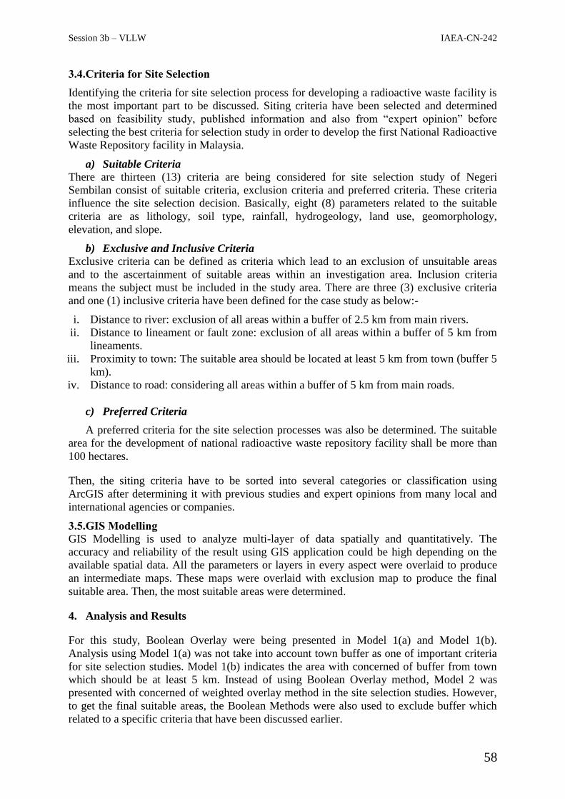
Session 3b – VLLW IAEA-CN-242
58
3.4.Criteria for Site Selection
Identifying the criteria for site selection process for developing a radioactive waste facility is
the most important part to be discussed. Siting criteria have been selected and determined
based on feasibility study, published information and also from “expert opinion” before
selecting the best criteria for selection study in order to develop the first National Radioactive
Waste Repository facility in Malaysia.
a) Suitable Criteria
There are thirteen (13) criteria are being considered for site selection study of Negeri
Sembilan consist of suitable criteria, exclusion criteria and preferred criteria. These criteria
influence the site selection decision. Basically, eight (8) parameters related to the suitable
criteria are as lithology, soil type, rainfall, hydrogeology, land use, geomorphology,
elevation, and slope.
b) Exclusive and Inclusive Criteria
Exclusive criteria can be defined as criteria which lead to an exclusion of unsuitable areas
and to the ascertainment of suitable areas within an investigation area. Inclusion criteria
means the subject must be included in the study area. There are three (3) exclusive criteria
and one (1) inclusive criteria have been defined for the case study as below:-
i. Distance to river: exclusion of all areas within a buffer of 2.5 km from main rivers.
ii. Distance to lineament or fault zone: exclusion of all areas within a buffer of 5 km from
lineaments.
iii. Proximity to town: The suitable area should be located at least 5 km from town (buffer 5
km).
iv. Distance to road: considering all areas within a buffer of 5 km from main roads.
c) Preferred Criteria
A preferred criteria for the site selection processes was also be determined. The suitable
area for the development of national radioactive waste repository facility shall be more than
100 hectares.
Then, the siting criteria have to be sorted into several categories or classification using
ArcGIS after determining it with previous studies and expert opinions from many local and
international agencies or companies.
3.5.GIS Modelling
GIS Modelling is used to analyze multi-layer of data spatially and quantitatively. The
accuracy and reliability of the result using GIS application could be high depending on the
available spatial data. All the parameters or layers in every aspect were overlaid to produce
an intermediate maps. These maps were overlaid with exclusion map to produce the final
suitable area. Then, the most suitable areas were determined.
4. Analysis and Results
For this study, Boolean Overlay were being presented in Model 1(a) and Model 1(b).
Analysis using Model 1(a) was not take into account town buffer as one of important criteria
for site selection studies. Model 1(b) indicates the area with concerned of buffer from town
which should be at least 5 km. Instead of using Boolean Overlay method, Model 2 was
presented with concerned of weighted overlay method in the site selection studies. However,
to get the final suitable areas, the Boolean Methods were also used to exclude buffer which
related to a specific criteria that have been discussed earlier.

Session 3b – VLLW IAEA-CN-242
59
4.1.Boolean Overlay (Model 1a and Model 1b)
To well describe Boolean Overlay Method in the ArcGIS interface, there are some steps and
processes which need to be followed before selecting the most potential area for the disposal
facility. The result maps produced after geospatial data processing in ArcGIS are shown in
Figure 1 as follows:-
Model 1(a) Model 1(b)
FIG 1: Comparison between Model 1(a) and Model 1(b). Model 1(a) before considering buffer 5 km
from town and Model 1(b) after considering buffer 5 km from town
4.2.Weighted Overlay (Model 2)
Weighted sum overlay techniques have been applied in order to overlay the map layers.
Weighted overlay is a technique for applying a common scale of values to diverse and
dissimilar input data to create an integrated analysis. To produce the final output raster or
suitability map, weighted sum overlay of the cell values for each input raster are multiplied
by the raster's weight. The maps resulting from this weighted sum overlay for site suitability
area is shown in Figure 2.
FIG 2: More potential areas were identified (in white color) by using Model 2 analysis
5. Discussion
Boolean Overlay and Weighted Sum Overlay techniques have been applied In order to
overlay the map layers. Boolean Overlay method are also known as Binary Overlay which is
a technique of grid analysis systems using AND function to combine the binary scores of
different criteria. This technique also eliminating any cells that did not score “good” in all
criteria. An OR function used to allow minimum risk approach where all cells that scored
“good” at least one criterion are selected as suitable.
Session 3b – VLLW IAEA-CN-242
60
Generally, weighted overlay is a technique that has been used by many scientists or
researcher with using a common scale of values to diverse and dissimilar input data for
creating an integrated analysis. In this study, different map layers characterizing site
suitability of the potential area were weighted using the weights derived from expert opinions
and literature review papers. In the weighted sum overlay, the cell values of each input raster
are multiplied by the raster's weight criteria weights.
From the results and analysis of Model 1(a), six (6) suitable areas were identified which is
located in Mukim Labu, Negeri Sembilan area. After considering town buffer 5 km from
town, only one (1) suitable site was identified which is also in Mukim Labu as presented in
Model 1(b).
Then, the output results from the process were added in order to produce the output raster.
These output raster need to be reclassified again into five (5) classes to show the importance
of the layers. Then, the reclassified raster layers were converted into vector maps by using
raster to polygon tools. However, weighted sum overlay used in the Model 2 also integrates
with Boolean Overlay process to erase the exclusion areas and intersect the inclusion area in
order to produce the final output raster or suitable area maps for developing the radioactive
waste repository facility.
With using Boolean Overlay and Weighted Overlay methods for Model 2, the identified
suitable site areas were scattered into several location in the east, west, and north of Negeri
Sembilan.
6. Conclusions
The suitable sites are located at the Mukim Labu area in the district of Seremban from the
west of the Negeri Sembilan state. By analyzing the potential area with coverage area of 100
hectares or 1 km2, there are three most potential sites to be selected for developing
radioactive waste disposal facility. This study provides an opportunity to explore a survey
method to find potential site for a low level radioactive waste repository in the state of Negeri
Sembilan, Malaysia using remote sensing and GIS technologies. Spatial data representing
geological, meteorological hydrogeological, and surface process were utilized for assessing
and characterizing the suitability of potential sites.
REFERENCES
[2] INTERNATIONAL ATOMIC ENERGY AGENCY, Siting of Near Surface Disposal
Facilities, IAEA Safety Series No. 111-G-3.1, Vienna (1994).
[1] Chuang, W-S., Chi, L-M., Tien, N-C., and Chang, F-L., Site Selection for the Disposal
of LLW in Taiwan. Proceeding of the Waste Management Conference, Feb. 26 –
March 2, Tucson, AZ, USA (2006).
[2] Huang, L.X., Sheng, G., and Wang, L., GIS Based Hierarchy Process for the Suitability
Analysis of Nuclear Waste Disposal Site. Journal of Environmental Informatics
Archives, Vol. 4, 289-296 (2006).
[3] Risoluti, P., Ciabatti, P., and Podda, A., The Site Selection Process Under Way in Italy
For LLW Repository and HLW Storage. Journal of Radioactive Waste Management
and Environmental Remediation, Roma, Italy (1999).

Session 3b – VLLW IAEA-CN-242
61
[4] Malczewski, J., GIS and Multicriteria Decision Analysis. John Wiley & Sons, New
York, pp. 392 (1999).
[5] Abdullah, C.H., Mohamad, A., Yusof, M.A.M., Gue, S.S. & Mahmud, M.,
“Development of Slope Management in Malaysia”, Malaysia (2007).
[6] S.A., Grant, I.K., Iskandar, Contaminant Hydrology - Cold Region Modelling. CRC
Press, London, New York.89-90 (2000).
[7] Guidelines for Slope Design – Slope Engineering Branch, Public Work Department
Malaysia, (2010).
[8] K. D., Lachman, P.G., Harrington, Retrievability as proposed in the U.S. High-level
Radioactive Waste and Spent Nuclear Fuel Repository Concept. W.M’01 Conference,
Las Vegas, Nevada (2001).
[9] Soil Survey Staff, Soil Survey Manual. United States Dept. of Agri. U. S. Government
Printing Office, Washington, D. C. 20402. pp. 136-146 (1993).
[10] Adzemi M.A., Land Evaluation System for Elaeis Guineensis Jacq. Cultivation in
Peninsular Malaysia. Universiti Putra Malaysia. pp. 6-7 (1999).
Session 3b – VLLW IAEA-CN-242
62
03b – 14 / ID 124. Disposal of Very Low Level Waste & Low Level Waste
REGULATORY APPROACH FOR THE ASSESSMENT OF THE LICENCE
APPLICATION FOR RADIOACTIVE WASTE MANAGEMENT FACILITIES IN
AUSTRALIA
S. Sarkar
Regulatory Services Branch, Australian Radiation Protection and Nuclear Safety Agency
(ARPANSA), PO Box 658, Miranda, NSW 1490, Australia
E-mail contact of main author: [email protected]
Abstract. This paper describes the regulatory approach of Australian Radiation Protection and Nuclear Safety
Agency (ARPANSA) for assessing the operating licence application for radioactive waste management
facilities. These facilities relate to predisposal management of radioactive waste. ARPANSA is the regulatory
authority for commonwealth entities operating nuclear installations including radioactive waste management
facilities. In assessing the application for nuclear installations the ARPANSA assessors prepare a Regulatory
Assessment Report (RAR), which is a recommendation to the Chief Executive Officer (CEO) of ARPANSA
whether to issue a licence to site, construct, operate and decommission facilities. The key elements of
ARPANSA’s assessment include plans and arrangements for managing safety, safety case, use of defence-in-
depth and conservative proven design and engineering practice, operational limits and conditions, and use of
international best practice. Compliance monitoring of licenced facilities are undertaken through regular
reporting, site visits and a risk-based planned inspection program.
Key words: radioactive waste management, regulatory assessment, predisposal management
1. Introduction
In Australia the main legislation and regulatory framework governing the safety of nuclear
installation, radiation facilities and radioactive material is the Australian Radiation
Protection and Nuclear Safety Agency Act 1998 (the Act) and the Australian Radiation
Protection and Nuclear Safety Regulations 1999 (the Regulations). The objective of the Act is
to protect the health and safety of people and the environment from the harmful effects of
radiation. The Act gives the CEO power to attach conditions to the licence for operation of
the facility.
Nuclear installations that operate under ARPANSA facility licence include research reactor,
radioisotopes production facilities, radioactive waste management and spent fuel
management facilities. All of Australia’s existing nuclear installations are under the effective
control of the Australian Nuclear Science and Technology Organisation (ANSTO). Though
some other Commonwealth entities operate radioactive waste management facilities nuclear
operational wastes are managed by ANSTO. The licensed waste management facilities
operated by ANSTO include:
Low level solid waste facilities for handling, processing and storage
Intermediate level solid waste facilities including storage of vitrified waste generated
from reprocessing of research reactor fuel, and various solid waste and solid waste
containing LEU generated from production of molybdenum-99
Low level liquid waste including storage, treatment and conditioning
Storage of intermediate level liquid waste

Session 3b – VLLW IAEA-CN-242
63
Storage of nuclear materials and safeguards materials
In 2014, ARPANSA issued the licence to site and construct an intermediate level liquid waste
conditioning facility to process the intermediate level liquid waste generating from the
production of molybdenum-99. Synroc (synthetic rock) technology, developed by ANSTO,
will be used to condition such intermediate level liquid waste.
2. Discussion
The ARPANSA regulatory approach is non-prescriptive but provides guidance and therefore,
the licence holder has flexibility in developing plans and arrangements to give appropriate
safety. To help judge the adequacy of the plans and arrangements, and safety cases
ARPANSA has published Regulatory Guidelines [1], Regulatory Assessment Principles [2]
and Regulatory Assessment Criteria [3]. These have been developed drawing on past
experience, best practice and international standards such as International Atomic Energy
Agency (IAEA).
An updated safety case is required for each of the principal stages in the life of a facility. The
safety case includes the design information for the facility, including the operational limits
and conditions (OLCs) within which the facility must operate, and a safety analysis that is
documented in the safety analysis report (SAR). The extent and rigour of the SAR should be
commensurate with the hazard categorisation of the facility. The margins between the
operational limits and conditions and the relevant safety limits are included in the SAR. As
part of the safety analysis report the licence holder must categorise the hazard associated with
the facility and also categorise systems, structures and components by their safety
significance.
The safety analysis establishes the hazard of the facility according to the following
categories:
Hazard Category F1: where there is no potential for significant3 consequences outside
the facility.
Hazard Category F2: where there is potential for significant1 consequences on the site
outside the facility, but not outside the site.
Hazard Category F3: where there is potential for significant1 consequences outside the
site
The responsibility for demonstrating each relevant assessment principle rests wholly with the
licence holder. The operating organisation’s safety analysis can assist in demonstrating safety
to ARPANSA. An alternative to an ARPANSA principle may be acceptable to the CEO of
ARPANSA if the operating organisation clearly demonstrates that the alternative principle
provides a degree of safety based on the application of contemporaneous international best
practice in radiation protection and nuclear safety.
Regulatory assessment (safety evaluation) of the information described in the application is
the key aspect for granting authorisation to operate a nuclear installation. Of particular
importance in safety evaluation for a facility licence are the plans and arrangements for
managing safety. These plans require the demonstration of appropriate arrangements for:
effective control;
3 Some judgement is required on significance and guidance is given in the Regulatory Assessment Principles
and also need to be addressed in the SAR

Session 3b – VLLW IAEA-CN-242
64
safety management;
radiation protection;
radioactive waste management;
security;
emergency; and
environment protection
The plans and arrangements for managing safety are then assessed against regulatory
guidelines developed by ARPANSA [1]. In addition safety case is assessed against
ARPANSA’ assessment principles [2] and criteria [3] and the requirements of the
international standards such as those of the IAEA.
A licence may be subject to conditions as set out in the ARPANS Act and Regulations; or
imposed by the CEO. Such licence conditions are not surrogates for safety; they outline
certain additional requirements placed on the licence holder that will assure the CEO of
ARPANSA that the licence holder is undertaking the licensed activity safely.
3. Results
After assessing all the relevant information ARPANSA assessors prepared a regulatory
assessment report (RAR), which is a recommendation to the CEO of ARPANSA whether to
issue a licence to operate4 the waste management facilities. This report was based on the
results of the detailed assessment of the application and the resolution of issues resulted from
any public submission on the application. The RAR is a complete assessment of the
application for an authorisation to operate the waste management facilities. This report
demonstrates that the conduct for which the licence is sought can be effectively controlled to
provide adequate protection to the health and safety of the people and the environment. The
operation of the ANSTO waste management facilities are currently subjected to six licence
conditions as they relate to compliance reporting, periodic performance assessment and
discharge of radioactive waste, and compliance with OLCs.
4. Compliance Monitoring
Apart from regular reporting (quarterly and annually) by the licence holder and regular site
visits, a long-term schedule of inspection is used for regulatory compliance monitoring. The
complexity and risk inherent in each facility determines the scope and duration of each
inspection. The scope of the inspection is determined based on risk using a graded approach.
There are eight inspection areas covered during the baseline inspection period. For example,
a single inspection may last two weeks and involve just one of the eight areas; it may, on the
other hand, involve four areas and last only two days.
The following inspection areas, which are comprised of more specific modules, collectively
known as the Performance Objectives and Criteria, constitute the baseline schedule for each
licence. These areas are broad in scope and intended to cover all aspects of licence holder
performance.
i. Performance Reporting Verification: address the reporting culture, both internally and
externally, including discrepant or unreported performance data, performance
indicator verification, and compliance with operating limits and conditions.
4 the RAR is also prepared for the CEO whether to issue a licence for siting, construction and decommissioning
of facility

Session 3b – VLLW IAEA-CN-242
65
ii. Configuration Management: include evaluation of facility modifications, equipment
alignment, operability determinations, temporary facility modifications, and safety
system design and capability.
iii. Inspection, Testing, and Maintenance: include post-maintenance testing, in-service
testing and inspection, surveillance testing, and maintenance and work control.
iv. Training: address personnel training, the use of a systematic approach to training,
accredited operator training, etc.
v. Event Protection: include adverse weather, fire protection, flooding, bush fires, land
management, etc.
vi. Security: include aspects of security arrangements and requirements. Modules also
include infrequently conducted tests or evolutions, outage performance, etc.
vii. Radiation Protection: include access control, dosimetry, ALARA planning, radiation
monitoring instrumentation, effluent system monitoring, radioactive material
processing and transportation, etc.
viii. Emergency Preparedness and Response: include exercises and drills, emergency
response organisation testing, notification testing, etc.
There are also three cross-cutting aspects that may be addressed in each inspection, namely,
Human Performance, safety Culture, Performance Improvement.
5. Conclusion
The matters and process considered in the regulatory assessment provide an effective and
efficient regulatory approach for safe and secure operation of nuclear and radiation facilities
including radioactive waste management facilities. Australian government is planning to
construct a National Radioactive Management Facility (NRWMF) to provide a centralised
location for the disposal of low level waste and storage of intermediate level solid waste
facilities. ARPANSA will apply similar regulatory approach to the NRWMF.
REFERENCES
[1] Australian Radiation Protection and Nuclear Safety Agency, ARPANSA, Regulatory
Guide: Plans and Arrangements for Managing Safety, (2014)
[2] Australian Radiation Protection and Nuclear Safety Agency, ARPANSA, Regulatory
Assessment Principles for Controlled Facilities, RB-STD-42-00, (2001)
[3] Australian Radiation Protection and Nuclear Safety Agency, ARPANSA, Regulatory
Assessment Criteria for the Design of New Controlled Facilities and Modifications to
Existing Facilities, RB-STD-43-00, (2001)

Session 3b – VLLW IAEA-CN-242
66
03b – 15 / ID 157. Disposal of Very Low Level Waste & Low Level Waste
SIMULATION AND STABILITY ANALYSIS OF NEAR SURFACE DISPOSAL
TRENCHES OF RADIOACTIVE WASTES BY USING FINITE ELEMENT METHOD
M. Boroumandi, A. Masood Taheria, A. Bagheri, S. Hasanlou, S. Momenzade
Iran Radioactive Waste Management Co. (IRWA)/ Iran Atomic Energy Organization/
Tehran/Iran
E-mail contact of main author: [email protected]
Abstract. At this paper, simulation and stability analysis of near surface disposal trenches in Anarak
Repository has been evaluated by finite element method. Emplacing of waste packages in the trenches impose
extra load to bottom and sides of trenches and it may increase deformations in the trench walls and cover. Also
corrosion of waste packages in long term may increase deformations and settlements and finally failure of
trenches may be occur. 2D model of trench containing waste packages with elasto-plastic behavior of materials
in finite element software has been designed and analyzed. Amount of deformations were measured and
considered in design of trenches.
Key Words: Disposal Trench, LILW, Finite Element Method, Stability Analysis.
1. Introduction
There are many disposal facilities for low and intermediate level radioactive wastes (LILW)
around the world. Near surface trench is one of the most common methods for disposal of
LILW [1, 2]. Effective and safe management of radioactive wastes needs an inclusive
program and consideration different criteria in trenches design [1, 3].
Trench design besides waste characteristics, site characteristics, type of barriers and
characteristics of cover layers are influencing on overall safety of disposal. LILW wastes
have different physical and chemical properties because of their different sources. For near
surface disposal trenches, suitable wastes are solid and solidified wastes with low leaching
rate of radionuclides and a small, non-degradable toxic chemical content [3, 4]. But in long
term, degradation of waste packages due to corrosion and also settlement of backfill layers
and cover can reduce safety of disposal trench. So evaluation of different aspects of trench in
design stage is an important step toward ensuring operational as well as long term safety
disposal.
Disposal of solid wastes with no treatment may effect on disposal performance and followed
by settlements due to low stiffness and high compressibility. So characteristic of wastes and
waste packages are important parameters in safety of disposal. Emplacing of waste packages
in the trench impose extra load to bottom of trenches and it may lead deformations in the
trench walls and bottom. Also corrosion of waste packages may increase deformation and
settlement. These deformations can impose cracks in cover and trenches walls and finally,
failure of trench may occur. For measurement of amount of deformations, design and
performing an elasto-plastic model performed.
Anarak Repository is Iran near surface disposal facility for LILW. Different properties of
wastes can effect on disposal safety, so these subject considered in design stage. The
objective of this paper is to study stability analysis of trenches in different conditions by
finite element methods.

Session 3b – VLLW IAEA-CN-242
67
2. Material and Methods
2.1.Study Area
The Anarak site has been selected as disposal facility for LILW in Iran. This site is located in
Isfahan province, about 24 km west of Anarak city and 90 km northeast of Naein as is shown
in Fig. 1. This site has been located in a syncline structure which consists of clay, marl and
sandstone layer that create good condition for controlling of radionuclides migration.
FIG. 1. Location of study area
2.2.Finite Element Simulation of Disposal Trenches
Numerical methods have been used in engineering project, extensively. Stability analysis of
near surface trenches in Anarak Repository has been evaluated by finite element method to
predict deformations and settlements. In primary stage of trenches design dimension of
trenches has been selected based on design criteria. 2-dimensional profile of trench with
wastes and backfill layers has been considered for convenient meshing and further analysis.
For assignment of material properties, elasticity properties of host rock, backfill layers and
waste packages should be considered. Mohr-Colomb criterion was selected for material
properties assignment. This area consist of two parts include of alluvium layers and host rock.
For determination of soil properties, direct shear test results were analyzed and for rocky part
uniaxial compression test and 3-axial compression tests were done on core samples obtained
from different boreholes. Summary of material properties were used in simulation presented
in Table I.
Cover weight take into account as surcharge load in model based on properties of different
layers and their thickness. It’s required to assigning the local body forces into the trench’s
various parts consisting body forces of barrels, cover layers, host rocks and backfill layered
soil. At this study density of host rock, waste packages and soil were considered as 2300,
2500 and 2100 N/m3, respectively.

Session 3b – VLLW IAEA-CN-242
68
TABLE I: MATERIAL PROPERTIES OF WASTE PACKAGES, SOIL AND ROCKS
Material Young Modulus (E)
GPa
Poisson ratio
(ν)
Friction Angle (φ)
Cohesion (C(
MPa
Host rock (clay and
marl stone)
1.96 0.23 40 6
Backfill and Soil layers 25*10-3 0.25 34 0.05
Waste Packages 204 0.29 - -
Waste analyzed in different alignment such as horizontal and vertical alignment and with
different properties of waste packages. Then by increment of loads of barrels, backfill layers
and cover layers, amount of deformations, stresses, strains and settlement in different parts of
trench were measured.
3. Results
3.1. Stability analysis of trenches with high stiffness and cover loads
The model was analyzed with high stiffness for consideration wastes in primary conditions.
After analysis by finite element model deformation of trenches were measured. Based on
mechanical properties of barrels and model results horizontal alignment have been chosen for
waste emplacement in trenches. The results showed that maximum stress and deformation are
0.64 MPa and 1.96 cm, respectively. On the other hand the amount of plastic strain measured
equal to 3.3*10-1
and there is no plastic strain in trenches wall, which show stability of
trenches wall. So we can conclude the trenches wall against to loads of cover and barrels
remain stable and there is no problem in stability analysis of trenches wall.
Stability parameters have been met when the barrels are solidified with concrete and they are
stiff, but after a long period of time, barrels strength will be decreases because of the
corrosion of materials. So, low elasticity parameters (Poisson's ratio and Young's modulus) of
wastes were considered for stability analysis and maximum subsidence of radioactive wastes
has been measured.
5.1 Stability analysis of trenches with low stiffness and cover loads
One of important issues in near surface disposal trenches is long term behavior of wastes in
trenches. Waste packages in trenches will corrode and baring capacity of them will be
decreased. These deformations can be followed by settlements and decrease of performance
of covers.
So at this stage model was analyzed by low stiffness of barrels (0.5 MPa elasticity modulus
and 0.4 Poisson's ratio). Results showed with assumption of deformability behavior of
barrels and backfill layers, the amount of deformations increased to 28 cm. However strain
plastic in trenches wall remain zero, but stresses have been increased. These deformations are
presented in Fig. 2.

Session 3b – VLLW IAEA-CN-242
69
Total deformations with low stiffness Maximum stress with low stiffness of barrels FIG. 2. Deformation and stresses of model for wastes with low stiffness
4. Conclusion
Weights of cover layers, waste packages and backfill layers which are considered as external
loads can influences on trench's performance. Solid wastes and solidified waste after
corrosion will have very low strength and they can't tolerate external loads and finally
settlement may occur.
Finite element simulation for trench's geotechnical model (as one of simulation method) was
performed to analyze the trench deformations under different conditions. Displacement,
plastic strain and stress concentration in the trenches evaluated in different situation.
The results showed different amounts of deformation in different situations. The maximum
deformation has been measured in surface and cover layers and it's about 28 cm. Also
maximum stress in trenches wall is about 3.2 MPa. According to long term operation of
trenches, maximum deformations were considered for detailed design. So disposal of solid
and solidified wastes with low stiffness in near surface trenches should be operated with
corrective actions.
REFERENCES
[1] INTERNATIONAL ATOMIC ENERGY AGENCY, The Principles of Radioactive
Waste Management: A Safety Fundamental, Safety Series No. 111-F, IAEA, Vienna
(1995)
[2] HAN, K.W., HEINONEN, J., BONNE, A., Radioactive Waste Disposal: Global
Experience and Challenges, IAEA Bulletin 39 1 (1997) 33–41
[3] INTERNATIONAL ATOMIC ENERGY AGENCY, Technical considerations in the
design of near surface disposal facilities for radioactive waste, IAEA-TECDOC-1256,
Vienna (2001).
[4] INTERNATIONAL ATOMIC ENERGY AGENCY, Disposal of Radioactive Waste,
Specific Safety Requirements, IAEA-SSR-5, Vienna (2011).

Session 3b – VLLW IAEA-CN-242
70
03b – 16 / ID 175. Disposal of Very Low Level Waste & Low Level Waste
DESIGN OF A NEAR SURFACE DISPOSAL FACILITY FOR LOW AND
INTERMEDIATE LEVEL RADIOACTIVE WASTE IN ZARIA, NIGERIA
1A. Ibrahim, D. Kula
2
1Nigerian Nuclear Regulatory Authority, Abuja, Nigeria
2Department of Mechanical Engineering Ahmadu Bello University Zaria, Nigeria
E-mail contact of main author: [email protected]
Abstracts. Near surface disposal facility with the capacity for receiving, treating, managing and disposing
about 500 waste containers of low and intermediate level radioactive waste was designed. The facility is
designed to have the administrative area, operational area and the final disposal trench. The design is intended to
manage low level waste currently generated in Nigeria from the use of nuclear applications i.e. Medical,
Industrial, nuclear well logging, research and training, it’s also designed to efficiently handle intermediate level
waste expected to be generated from the expansion of nuclear technology in Nigeria, and the proposed Nuclear
Power Plant (NPP). The final disposal trench is sectioned to provide for future waste disposal, in such a way that
until a section is fully occupied and sealed before other sections are utilized. The trench is designed to be safely
operated, secured from unauthorized access to prevent been used for malicious intent and to meet Nigerians
safeguards obligations. The trench is shielded to attenuate gamma and low neutron with mathematically
determined concrete thickness of 1.4meters for surface shield. With these shield the background radiation within
the trench would not exceed 𝟎. 𝟑 𝒎𝑺𝒗/𝒚𝒓 cumulatively when operational. The cost estimate for the trench was
determined to cost N24,103, 900.00
1. Introduction
Nuclear technology and application in Nigeria is fast developing; Nigeria and many other
developing countries use nuclear application in everyday activities, in health sector,
agricultural sector, oil and gas Industries, Construction industries, Manufacturing Industries,
Education and training. [1]. Nigeria has a nuclear power program which has been going on
for quite a long time. The country hopes to have its first nuclear power plant by 2025, and
efforts to build a new research reactor of 7MW capacity are underway [2]. The issue of
nuclear waste management comes up whenever there are nuclear programs, the challenges of
nuclear waste is enormous, due to safety and security concerns. Radiological waste from the
hospital, from disuse sources and the most delicate and controversial waste from nuclear
power plant spent fuel. Under typical circumstances, a developing country using sealed
radioactive sources may generate hundreds of disused sources with low levels of radioactivity
over several years. Although Nigeria do not have nuclear power plant yet, but the presence of
thousands of radioactive sources used in the oil and gas sector also calls for concern. Low
activity sources pose the larger challenge because they exist in large quantities around the
world and in different forms and variations [3].
2. Materials and Methods
The design of the near surface facility for radioactive waste, the facility consists of various
facilities which would help in waste management operations before final disposal. It is sub
divided it two major sections, Administrative and Operational

Session 3b – VLLW IAEA-CN-242
71
2.1. Administrative Section
The Administrative section is meant for daily administrative activities, with provisions for
reception, offices for records and other administrative duties, security office for monitoring
access and physical protection of the facility and the surroundings.
2.2. Operation section
Operational section is where the predisposal operation takes place before the waste is finally
disposed in the disposal repository. It consists of Interim Storage facility, Unloading and
sorting facility, General services facility, waste condition facility and provisions for
decontamination facility which would serve as in and exit point for contamination
monitoring. The scope of the design is emphasize on the final disposal trench for low and
intermediate radioactive waste with the objective of isolating the waste from people and the
environment until natural processes of decay & dilution prevent any radionuclide from
returning in concentrations that pose a hazard [4].
2.3 Zaria Site Characteristic
It was important to consider and know the sub soil formation of Zaria and Ahmadu Bello
University were the trench was designed for, the only research reactor in Nigeria is also
located in Zaria, there are also possibilities they consider this design when they plan to build
a new radioactive waste facility. The A.B.U Zaria in being part of the kubani, basin, is
therefore underlain by Precambrian rock of the Nigerian baseman. The proposed site is
situated within the south-western part of the campus and underlain by muscovite
biotiticgnoiss. The alluvial deposal in Zaria area consists of granite, sands, silts, and clay.
Thickness ranges from 5 - 15m and the aquifer ranges from 28 – 34m [5].
2.4 Trench design Consideration
The trench is designed for disposal of low and intermediate waste to take care of current and
future radioactive waste to be generated from the expanding nuclear energy application in
Nigeria and nuclear power program. The facility is designed to accommodate more than four
hundred containers of low and intermediate level waste, low level waste in metal containers
while intermediate level waste in concrete containers, it’s expected that before the waste is
brought into the trench for final disposal it must be conditioned to meet the facility waste
acceptance criteria for solid waste. The surface radiation of each waste container would not
exceed “𝟏𝟎 𝒎𝑺𝒗 𝒉⁄ “which is the IAEA Transport Regulations for exceptional case. The
trench is designed to be partitioned into four sections, this would provide disposal medium
for future expected waste, each section is designed to accommodate 100 drums and more
waste containers arranged in two columns or more depending on the numbers of waste
containers ready for disposal, the trench is sectioned to provide for future waste disposal, in
such a way that until a section is fully occupied and caped before the other section is utilized ,
this may take long period of time depending on the quantity of waste the facility is projected
to receive, each section would be independent from the other and they shall be shielded
separately at the top and walls of the trench.
2.5 Design Parameters

Session 3b – VLLW IAEA-CN-242
72
The trench is to be dug to a depth deep beneath the ground to 25 meters before the aquifer
this is to give reasonable distance to the aquifer to prevent ground water contamination. The
depth of the containers to the top soil of the trench is about 9 meters and the depth and
distance from the drums to the cap is estimated to be 5 meters. Drainage layer of about
200mm is also incorporated into the design to prevent leaching and it’s also an engineered
feature to help the integrity of the trench from chemical reactions. The trench is to be
backfilled at all sides with red clay and Betonite. Monitoring pipe is also incorporated into
the design to help monitor for contamination, and other activities, such as concentration,
temperature, pressure and activity inside the trench.
2.6` Shield Design Calculation
"𝒏 = 𝒙
𝑯𝑽𝑳" Where; 𝒙 = Thickness of shield, 𝑯𝑽𝑳 = Thickness of concrete permit
𝟏
𝟐 of the
incident radiation to pass “ 𝒏 = 𝒍𝒏(
𝜤°𝜤
)
𝒍𝒏 𝟐=
𝒍𝒏(𝜤°𝜤
)
𝟎.𝟔𝟗𝟑 ” , “𝒙 = 𝑯𝑽𝑳 ×
𝒍𝒏(𝜤°𝜤
)
𝟎.𝟔𝟗𝟑 ”
Note that 𝑯𝑽𝑳 of 𝑨𝒎𝟐𝟒𝟏 was considered because it has higher 𝑯𝑽𝑳 for concrete at
. 𝟓 𝒈 𝒄𝒎𝟑⁄ . Shielding factor from IAEA Safety Series No: 47. “In order to solve nuclear
waste problem you have to solve the americium problem [6].
𝑯𝑽𝑳 = 𝟔. 𝟗𝒄𝒎, 𝜤° = 𝟒𝟎𝟎𝟎 𝒎𝑺𝒗 𝒉⁄
𝟏𝟎 𝒎𝑺𝒗 𝒉⁄ was considered based on IAEA Transport Regulations for exceptional cases was
considered to optimize the shield. Therefore: multiply 400 drums × 𝟏𝟎 𝒎𝑺𝒗 𝒉⁄ , i.e 400
drums considered.
𝟎.𝟑 𝒎𝑺𝒗 𝒉⁄
𝟑𝟔𝟔 ×𝟐𝟒 = 𝟎. 𝟎𝟑𝟒 𝒎𝑺𝒗 𝒉⁄ ,……𝒏 =
𝒍𝒏(𝜤°𝜤
)
𝟎.𝟔𝟗𝟑
𝒏 = 𝒍𝒏 (
𝟒𝟎𝟎𝟎 × 𝟏𝟎𝟑 𝝁𝑺𝒗 𝒉⁄𝟎. 𝟎𝟑𝟒 )
𝟎. 𝟔𝟗𝟑
= 𝟐𝟎. 𝟏𝟕 (𝟔. 𝟗 Shielding factor from IAEA Safety Series No: 47), 𝒏
𝒙 = 𝑯𝑽𝑳 × 𝒏 ,𝒙 = 𝟔. 𝟗𝒄𝒎 × 𝟐𝟎. 𝟏𝟕 = 𝟏𝟑𝟗. 𝟏𝟕𝟑𝒄𝒎 ∴ 𝒙 = 𝒕𝒉𝒊𝒄𝒌𝒏𝒆𝒔𝒔 ≅ 𝟏. 𝟒 𝒎𝒆𝒕𝒓𝒆𝒔

Session 3b – VLLW IAEA-CN-242
73
FIG. 1.Plan of the Trench Design.
3. Conclusion
A trench with a capacity of storing and receiving over 400 low and intermediate level
radioactive waste was designed for disposing low and intermediate level waste in Zaria.
Design analysis was carried out for the disposal facility. The design concept of capping the
top of the trench was developed based on years of utilizing the trench and in expectation of
waste readily available for disposal, so that after each section is fully utilized before the other
section is used. With the effective shield provided by the design and arriving at 1.4 meters
thickness of concrete for the cover of trench the environment is expected to be safe from the
harmful effect of ionizing radiation.
REFERENCES
[1] Ibrahim. A, “Minimizing the risk of Proliferation and Nuclear / Radiological Terrorism
in Nigeria” Paper presented at Center for Non proliferation Studies, Paper, 3, California
(2014)
[2] Mallam, S.P. “Over view of Radioactive Waste Management in Nigeria”, Paper presented
at the National training Course on Radioactive waste management system responsibilities
allocation, Abuja 26-30 November 2012
[3] International Atomic Energy Agency (2016). IAEA Reaches Milestone in Disposal of
Radioactive Sources. Accessed from www.iaea.org. 2016
[4] International Atomic Energy Agency Technical Document“TECDOC-1515
“Development of specification in radioactive waste management” (2006), Accessed from
www-pub.iaea.org. 5th
February 2016
[5] Jimoh; 8, L.,“Geophysical Investigation of a Sewage Treatment Site at Ahmadu Bello
University, Zaria (Main Campus) using 2-D Electrical Resistivity Tomography”
(2011).(MSC Thesis) Department of Physics , Ahmadu Bello University, Zaria, Nigeria.

Session 3b – VLLW IAEA-CN-242
74
Tom, M. Scientist discovers how to remove radioactive toxic element americium.(2016)
Accessed April 10 2016 from www.ibitimes.co.uk.

Session 3b – VLLW IAEA-CN-242
75
03b – 17 / ID 183. Disposal of Very Low Level Waste & Low Level Waste
THE NATIONAL DISPOSAL FACILITY FOR RADIOACTIVE WASTE IN
BULGARIA
T. v Berlepsch1, E. Gonzalez Herranz
2, I. Stefanova
3, B. Haverkamp
1,
G. Nieder-Westermann1
1DBE TECHNOLOGY GmbH, Peine, Germany
2WESTINGHOUSE ELECTRIC Spain, Madrid, Spain
3Bulgarian State Enterprise for Radioactive Waste Management (SERAW), Sofia, Bulgaria
E-mail contact of main author: [email protected]
Abstract. The need for building a National Disposal Facility (NDF) is recognised by the Bulgarian
government and the Bulgarian State Enterprise for Radioactive Waste Management (SERAW). To address this
need SERAW is endeavouring to build a near-surface repository for short-lived low- and intermediate-level
radioactive waste to discharge its statutory responsibilities in waste management. The European Union finances
the establishment of the NDF through the Kozloduy International Decommissioning Support Fund (KIDSF).
SERAW placed a contract for the development of the design to the Consortium of Westinghouse Electric Spain
S.A.R, DBE TECHNOLOGY GmbH, and ENRESA. Two Bulgarian companies participate also in the project as
subcontractors – EQE Bulgaria and to a lesser extent КК–Project. After obtaining SERAW's approval for the
preferred repository conceptual design variant, the repository project usually referred to as R Project 5, focused
on developing the Technical Design and preparation of the Intermediate Safety Analysis Report (ISAR) that
demonstrates the safety and suitability of the proposed NDF design. These documents were delivered to the
relevant Bulgarian authorities. The required permits have either been received or are expected before the end of
2016. This paper summarises the main steps and achievements of R Project 5.
Key Words: R-Project 5, National Disposal Facility, Radioactive Waste Management,
Licensing.
1. Introduction
In the framework of the accession treaty to the European Union the Republic of Bulgaria
committed itself to the early decommissioning of the four WWER 440-V230 reactors at the
Kozloduy Nuclear Power Plant (KNPP). Due to this early decommissioning large amounts of
low and intermediate radioactive waste will arise much earlier than initially scheduled.
Consequently, Bulgaria has intensified its efforts to provide a near surface disposal facility
for low and intermediate level waste (LILW) with the required capacity. It is supported in this
endeavour by a compensation mechanism established by the European Union, the “Kozloduy
International Decommissioning Support Fund (KIDSF)”, aimed at alleviating the significant
impact of the early NPP phase out on Bulgaria`s economy. The fund is managed on behalf of
the European Union by the European Bank for Reconstruction and Development (EBRD).
In a series of projects the State Enterprise for Radioactive Waste (SERAW) selected a site for
the National Disposal Facility (NDF) in the vicinity of the KNPP at Radiana, which is located
on the terraces of the Danube River valley's south rim. This early work also specified
Enresa’s facility at El Cabril as the reference design for the NDF. SERAW placed a contract
for the development of the design of the NDF with the Consortium of Westinghouse Electric
Spain S.A.R and DBE TECHNOLOGY GmbH of Germany, with ENRESA, the Spanish
National Waste Management Agency providing technical review and support. Two Bulgarian
companies participate also in the project as subcontractors – EQE Bulgaria and КК–Project.

Session 3b – VLLW IAEA-CN-242
76
The project's official name is “Technical Design and ISAR Preparation for the National
Disposal Facility at Bulgaria”, usually referred to as “R-Project 5”.
The NDF design work started in October 2011. Initially, two repository conceptual designs
were developed considering the particular characteristics of the Radiana site. The most
favourable variant was selected by means of a formal multi-attribute analysis with evaluation
criteria such as operational and long-term safety, environmental impact, constructability,
initial investment, and operational costs. SERAW approved the recommended Conceptual
Design on December 2012, and authorised the Consortium to begin development of the
Technical Design. Since then the Technical Design work has been completed and submitted
to SERAW. Simultaneously to the preparation of the Technical Design for the NDF, the
consortium also developed the Intermediate Safety Analysis Report (ISAR), currently
awaiting final approval.
2. The Repository Design
The Radiana Site, a quasi-rectangular 46-hectare area with approximate maximum
dimensions of 470 m x 1250 m, is located between the KNPP Administrative Road
connecting the town of Kozloduy with the NPP on the north and Road No. 11 to the south
connecting Hurletz and Kozloduy. The site is located on slopping terrane between the second
and sixth loess terraces of the river Danube.
The NDF shall be able to accept and dispose of all Category 2a radioactive waste (RAW),
corresponding to what is usually referred to as Short-Lived, Low and Intermediate-Level
Waste (SL-LILW), arising in Bulgaria from the operation and dismantling of the national
nuclear facilities. According to forecasts the NDF will receive conditioned waste packed in
18,615 cubic-shaped concrete containers (i.e., waste packages). The waste packages have a
side length of 1.95 m and a weight of up to 20 tons. The total volume occupied by these
waste packages will be 138,200 m3. The radionuclide inventory is approximately 2.4 × 10
14
Bq.
The NDF design relies on a multiple barrier isolation system. The isolation function is
guaranteed by the system as a whole so that possible deficiencies of a barrier or its
degradation over the course of time are compensated by other barriers, thus ensuring that the
protection objectives are achieved. The safety of the facility is based on a defence-in-depth
concept consisting of a system of physical barriers and administrative measures.
For practical and operational safety reasons the repository facilities have been grouped into:
Disposal zone, in which the disposal cells are located
Building zone, in which the Waste Reception and Buffer Storage (WRBS) Building,
the site administration, control room and ancillary and support buildings are located.
The NDF has 66 disposal cells for waste package disposal. These disposal cells are located on
3 equal platforms, each with 22 disposal cells and their related systems. A first disposal
platform will be constructed prior to disposal start, the second approximately after 20 years,
and the third after 40 years of operation. The disposal cells are arranged in two lanes, each
with 11 disposal cells. The disposal cells are monolithic rectangular boxes with two inner
walls made of reinforced concrete, with a capacity for 288 waste packages emplaced in 3
chambers of 96 waste packages each (8 × 3 waste packages in plan, 4 layers in height). The
external dimensions of each disposal cell are 20.15 m long by 17.05 m wide. The height is
9.45 m measured from the foundation level up to the top of a full and sealed disposal cell.
Each storage platform will host 6,336 waste packages corresponding to about 20 years of
repository operation. The total disposal capacity of the NDF will be 19,008 waste packages.

Session 3b – VLLW IAEA-CN-242
77
After a disposal cell is fully loaded with waste packages, it will be closed with a reinforced
concrete slab. During the disposal process and construction of the concrete slab the disposal
cell will remain covered by a mobile roof to protect loading and closure operations from
inclement weather conditions. The mobile roof also houses the overhead crane used to
emplace waste packages into their final position within each disposal cell. Before the mobile
roof is relocated to the next disposal cell position, hydro insulation protective measures are
applied over the exposed surfaces of the closed disposal cell.
A critical component of the disposal system is the Infiltration Control Network, which
consists of a pipe system to collect and control the water that could enter a disposal cell after
closure and interact with waste. The pipes are located in an accessible underground gallery
below the disposal cells. The system includes a pipe connection coming from each disposal
cell and a collection tank. Water is exclusively driven by gravity.
The Building Zone contains the entire infrastructure needed for the efficient and safe
operation of the NDF. The most important structure in this zone is the Waste Reception and
Buffer Storage (WRBS) Building. The WRBS Building is designed to receive each
radioactive waste package delivered to the NDF by truck. The building also provides a buffer
storage capacity of 120 waste packages that allows for the regulation and optimization of the
waste package flow to the disposal cells.
The NDF has a single main access that links the Kozloduy NPP road with the Building Zone.
The waste package disposal operation begins in the WRBS Building waste package
loading/unloading area. Here an internal transport vehicle is loaded with a waste package.
This vehicle goes to the assigned disposal cell and parks under the mobile roof where the
overhead crane lifts the waste package and hoists it to its storage position within the disposal
cell.
At the end of NDF operations, a long-term multi-layer cover, specifically designed to prevent
the intrusion of water into the disposal cells during the surveillance phase will be constructed.
3. Repository Licensing
Licensing of a radioactive waste repository in Bulgaria comprises separate licenses pursuant
to different legal instruments that govern the use of land and spaces, the environmental
impact of any industrial facility and/or construction works, as well as nuclear matters.
Ancillary permits including site security, fire protection, and protection of the groundwater
are required.
The NDF is specifically defined as a nuclear facility by the "Act on the Safe Use of Nuclear
Energy" (ASUNE) and must be licensed as per the ASUNE requirements. In addition, as all
industrial facility construction or infrastructure works in Bulgaria, the requirements of the
Act on Territory Arrangement also apply. The responsible licensing authority for the NDF as
nuclear facility is the Bulgarian Nuclear Regulatory Agency (BNRA). The responsible
organisation for licensing the NDF as per the requirements of the Act on Territory
Arrangement is the Ministry of Regional Development and Public Works (MRDPW). The
investment proposal on establishment of the NDF is also subject to an Environmental Impact
Assessment (EIA). The responsible authority for issuing decisions on the EIA is the
Bulgarian Ministry of Environment and Waters (MEW).
In addition, commitments under the EURATOM Treaty have to be followed. Article 37
requires consideration of the cross-border effects, in the case of the NDF especially upon
Romania. Article 41 requires projects relating to this article to be communicated to the

Session 3b – VLLW IAEA-CN-242
78
European Commission (EC) in order to allow the EC to discuss with the Investor (i.e.,
SERAW) all aspects of the investment project.
3.1.Technical Design – TD
In order to assure sufficient quality in the development and review of the Technical Design
the document has been structured following Bulgarian requirements for investment projects
into 19 separate design parts. Additionally, in each design part of the Technical Design the
documentation, which corresponds to the respective buildings and facilities in the General
Layout Plan (GPL), is arranged in up to 23 separate sub-parts. The use of sub-parts is
optional, i. e. they are only considered if necessary. For example, the design part Architecture
is subdivided into 19 subparts describing in detail the fundamental connections and
parameters for the various facilities and common areas, while there is only one subpart for the
Design Part Geodesy providing the topographical base for the project. In total the Technical
Design documentation prepared by the Consortium fills around 50 folders with
approximately 6500 pages.
3.2.Intermediate Safety Analysis Report – ISAR
As previously stated, the license for repository construction requires completion of an
Intermediate Safety Analysis Report (ISAR). The ISAR assesses the behaviour of the
disposal facility and, in particular, the NDF potential radiological impact on humans and the
environment. The report considers potential pathways for radionuclide releases into the
environment and the resulting health effects. The ISAR shall provide convincing proof that
the NDF design, as laid down in the Technical Design documents, and the planned operations
are safe in accordance with applicable regulations, taking into account:
Characteristics of the site
Characteristics of the wastes to be disposed
Planned activities and personnel involvement
Characteristics of the risks associated with the NDF
4. Project Implementation
As previously described the NDF will be constructed in three stages. The auxiliary
installations and the first platform of disposal cells will be built during the first stage and will
provide a fully compliant disposal facility, but without the full complement of disposal cells.
Subsequently, a second and third stage of construction will expand NDF to full capacity. The
design takes into consideration ongoing operations during the second and third expansion
campaigns. To minimize construction interference on operations a secondary access road
(also used as an emergency evacuation route) will be used to access construction areas.
Full implementation of the project will include the following NDF lifecycle phases:
Operation: 60 years – receiving and emplacing waste packages
Closure phase after disposal end: 15 years – building of multi-layer cover;
Institutional control after closure: 300 years – surveillance of site.
5. OUTLOOK
In principle all licensing documents have been finalised and submitted by SERAW to the
responsible authorities. In expectance of a generally positive acknowledgement of the
submitted documentation SERAW signed a contract with NUKEM for the construction of the

Session 3b – VLLW IAEA-CN-242
79
NDF on July 7th
, 2016. It is expected that construction works can commence at the beginning
of next year.


