

DOE sCO2 Workshop 2019
All Materials Copyright 2019 Solar Dynamics
National Renewable Energy Laboratory
Golden, Colorado
November 1, 2019
Bruce Kelly, SolarDynamics LLC
Molten Nitrate SaltThermal Energy Storage
SolarDynamics
Slide 2 Copyright 2019 Solar Dynamics 11/01/2019
Nitrate Salt Thermal Storage
Commercial projects
Solar parabolic trough and central receiver
Two-tank (hot tank and cold tank) designs
No thermocline systems have been built to date
Nitrate salt
Tank design basis
Foundation design basis
Experience from solar thermal projects

SolarDynamics
Slide 3 Copyright 2019 Solar Dynamics 11/01/2019
Commercial Solar Projects
Capacity, Storage, Capacity, Storage,
Project MWe hours Project MWe hours
Andasol-1 Trough 50 7.5 Khi Solar One Tower 50 2
Andasol-2 Trough 50 7.5 La Africana Trough 50 7.5
Andasol-3 Trough 50 7.5 La Dehesa Trough 49.9 7.5
Arcosol 50 - Valle 1 Trough 49.9 7.5 La Florida Trough 50 7.5
Arenales Trough 50 7 Manchasol-1 Trough 49.9 7.5
Ashalim Trough Trough 121 4.5 Manchasol-2 Trough 50 7.5
Aste 1A Trough 50 8 NOOR I Trough 160 3
Aste 1B Trough 50 8 NOOR II Trough 200 7
Astexol II Trough 50 8 NOOR III Tower 150 7
Bokpoort Trough 55 9.3 Planta Solar 10 Tower 11.02 1
Casablanca Trough 50 7.5 Planta Solar 20 Tower 20 1
Cerro Dominator Tower 110 17.5 Solana Generating Station Trough 280 6
Crescent Dunes Tower 110 10 SunCan Dunhuang 10 MW Phase I Tower 10 15
DEWA Tower Project Tower 100 10 Termesol 50 - Valle 2 Trough 49.9 7.5
DEWA Trough Unit 1 Trough 200 10 Termosol 1 Trough 50 9
DEWA Trough Unit 2 Trough 200 10 Termosol 2 Trough 50 9
DEWA Trough Unit 3 Trough 200 10 Xina Solar One Trough 100 5.5
Extresol-1 Trough 49.9 7.5 Shagaya Trough 50 10
Extresol-2 Trough 49.9 7.5 Ilanga Trough 100 5
Extresol-3 Trough 50 7.5 Supcon Delingha Tower 10 2
Gemasolar Thermosolar Plant Tower 19.9 15 Supcon Delingha Tower 50 7
Kathu Solar Park Trough 100 4.5 CGN Delingha Trough 50 9
KaXu Solar One Trough 100 2.5 Suncan Dunhuang Tower 100 11

SolarDynamics
Slide 4 Copyright 2019 Solar Dynamics 11/01/2019
Commercial Solar Projects - Continued
250 MWe Solana project, with 6 storage units

SolarDynamics
Slide 5 Copyright 2019 Solar Dynamics 11/01/2019
Commercial Solar Projects - Continued
Thermal storage tanks at the 110 MWe Crescent Dunes central receiver project

SolarDynamics
Slide 6 Copyright 2019 Solar Dynamics 11/01/2019
Nitrate Salt
60 weight percent NaNO3 and 40 weight percent KNO3
Not the eutectic (50 mole percent each), but less expensive
Freezing range of 220 to 240 °C
Oxidizing material, but chemically stable
In air, as the ullage gas in the thermal storage tanks
In water, when exposed to leaks in the steam generator
Very low vapor pressure; less than 20 Pa at 600 °C
Upper temperature limit of ~ 600 °C
First equilibrium reaction: NO3 ↔ NO2 + ½ O2
Second (quasi) equilibrium reaction: NO2 ↔ NO(g) + O-
Oxide ions react to form nickel oxide, iron oxides, and soluble chromium oxides
At oxide concentrations above ~ 200 ppm, corrosion rates exceed commercially
acceptable values
SolarDynamics
Slide 7 Copyright 2019 Solar Dynamics 11/01/2019
Tank Design Basis
Large volumes (15,000 m3) and low vapor pressures (10 Pa) lead to a flat bottom
tank with a self-supporting dome roof as the lowest cost approach
Necessarily requires the tank to be supported by, and to interact with, a
foundation
‘Closest’ design code is American Petroleum Institute 650 - Welded Tanks for Oil
Storage
API 650 is limited to 260 °C
For higher temperatures, allowable material stresses are taken from ASME B&PV Code
Section II - Materials
Combination of Codes must be approved by the local Authorized Inspector

SolarDynamics
Slide 8 Copyright 2019 Solar Dynamics 11/01/2019
Tank Design Basis - Continued
Materials
Carbon steel for temperatures below 375 °C
Defined by corrosion rate and allowable long-term creep deformation
Type 304L stainless steel for temperatures between 375 °C and 538 °C
Ferritic materials (chrome-moly) offer acceptable corrosion resistance
However, the higher chrome alloys require post weld heat treatment
Type 347H stainless steel for temperatures above 538 °C
‘H’ grade stainless steels (> 0.04 percent C) are required
However, the common types, such as 304H and 316H, can be permanently damaged by
intergranular stress corrosion cracking
Stabilized stainless steels, including Type 321 and Type 347, are less susceptible to
intergranular stress corrosion cracking

SolarDynamics
Slide 9 Copyright 2019 Solar Dynamics 11/01/2019
Tank Design Basis - Continued
Requirements not specifically addressed in API 650 or ASME Section II
The tank must be preheated to 350 °C prior to filling with salt
The tank operates through daily pressure and temperature cycles
The low cycle fatigue life must be at least 10,000 cycles
The tank, when full, can either increase in temperature or decrease in temperature.
Friction between the thin floor (6 to 8 mm) and the foundation places the floor into either
tension or compression.
The EPC must specify weld filler materials, weld procedures, and post weld heat
treatments
Post weld heat treatment of carbon steel is specified in Section VIII
Post weld heat treatment of stainless steel is optional in Section VIII; i.e., an EPC
decision
Tricky decision for stabilized stainless steels

SolarDynamics
Slide 10 Copyright 2019 Solar Dynamics 11/01/2019
Tank Design Basis - Continued
Tank inlet piping and eductor arrangements may not provide perfect mixing,
particularly during trip conditions
Foundation temperatures are high enough to produce soil desiccation and
oxidation of organic material. To prevent excessive foundation settlement, cooling
must be provided to limit soil temperatures to 75 °C.
The EPC must develop
Tank specifications based on API 650, ASME Section II, Section VIII Division 1 (infinite
fatigue life), Section VIII Division 2 (low cycle fatigue life), and modifications to the rules in
API 650
CFD analyses of flow distributions during transient conditions, and the associated FEA
analyses of the floor and wall stresses
Operating procedures consistent with a 30-year fatigue life
The storage system, particularly the hot tank, is neither isobaric nor isothermal

SolarDynamics
Slide 11 Copyright 2019 Solar Dynamics 11/01/2019
Foundation Design Basis
Concrete base slab
Forced convection air cooling of the concrete
Rigid perimeter ring wall of a refractory material (cast or bricks) to accommodate
the concentrated vertical loads from the wall and the roof. Expanded clay as the
sole foundation material has repeatedly been shown not to work.
Expanded glass as the primary insulation material
Contiguous drip pan to isolate the foundation from a salt leak
Salt has a higher thermal conductivity than the insulation
Foundation thermal losses will markedly increase due to salt contamination
Sand layer to reduce friction forces between bottom of the tank and the
foundation
Reduce the potential for buckling of the thin floor plates
SolarDynamics
Slide 12 Copyright 2019 Solar Dynamics 11/01/2019
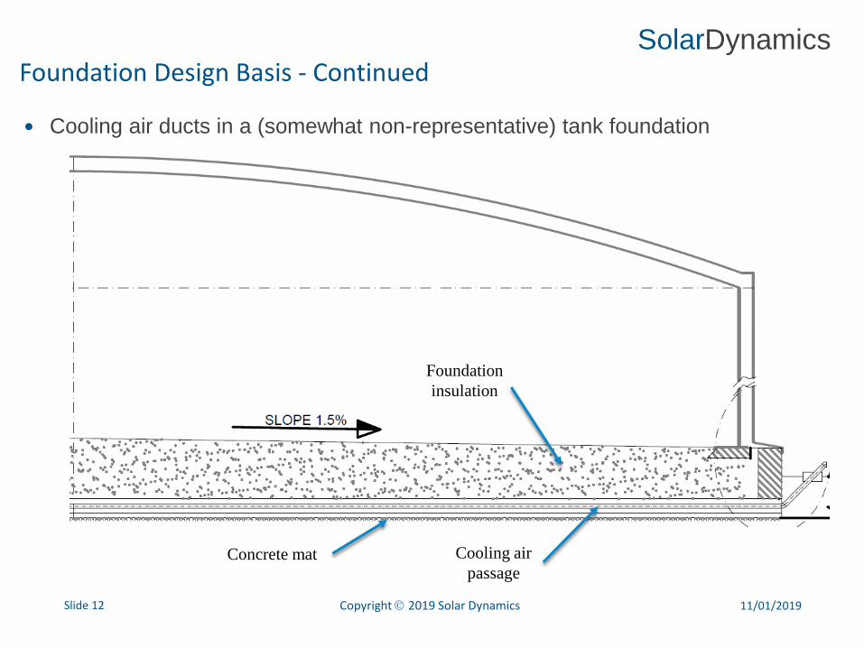
Foundation Design Basis - Continued
Cooling air ducts in a (somewhat non-representative) tank foundation
Foundation
insulation
Concrete mat Cooling air
passage

SolarDynamics
Slide 13 Copyright 2019 Solar Dynamics 11/01/2019
Foundation Design Basis - Continued
Tank foundation cooling air passages

SolarDynamics
Slide 14 Copyright 2019 Solar Dynamics 11/01/2019
Foundation Design Basis - Continued
Hot tank foundation
Concrete Foundation
Cast
Refractory
Hard
Firebrick
500 mm
450 mm
Foamglas
Insulation
Tank
Shell
Drip Pan
750 mm
60 mm
Insulating
Firebrick
6 in. Pipe
Mineral
Wool

SolarDynamics
Slide 15 Copyright 2019 Solar Dynamics 11/01/2019
Nitrate Salt Pumps
Pumps with extended
shafts draw suction from
bottom of storage tanks
Turbine pumps, with
bearings lubricated by
the salt
Avoids need for below-
grade pump sumps, fed
by gravity from storage
tanks
Reliability has been
excellent

SolarDynamics
Slide 16 Copyright 2019 Solar Dynamics 11/01/2019
Parabolic Trough Thermal Storage
Indirect thermal storage
Therminol heat transfer fluid in the collector field
Nitrate salt thermal storage fluid
Oil-to-salt heat exchange during charging; salt-to-oil heat exchanger during
discharging
300 °C cold tank temperature, and 385 °C hot tank temperature
All carbon steel construction
Tank dimension limits
12 m tall based on allowable soil bearing pressures
40 m diameter to avoid ASME Section II requirements for post weld heat treatment of
carbon steel with thicknesses greater than 38 mm
78 tanks built to date, with only 1 reported leak (perhaps due to a weld defect)

SolarDynamics
Slide 17 Copyright 2019 Solar Dynamics 11/01/2019
Central Receiver Thermal Storage
Receiver supplies salt directly to the cold tank or to the hot tank based on
diversion valve positions
295 °C cold tank temperature, and 565 °C hot tank temperature
Carbon steel cold tank, and Type 347H stainless steel hot tank
Tank dimensions are similar to parabolic trough projects
4 storage systems built to date: Solar Two; Gemasolar; Crescent Dunes; and
Noor III
No cold tank leaks
4 hot tank leaks to date: 2 at Gemasolar; and 2 at Crescent Dunes
Primarily due to problems with the foundation
No evidence of stress relaxation cracking, intergranular stress corrosion cracking,
incorrect selection of weld filler materials, or unexpected corrosion processes

SolarDynamics
Slide 18 Copyright 2019 Solar Dynamics 11/01/2019
Central Receiver Thermal Storage - Continued
Revised hot tank design and operation
Tank specification addenda to API Standard 650 regarding friction forces between the
foundation and the floor
For transient conditions, CFD/FEA analyses of salt flow distributions, metal
temperature distributions, and floor and wall stress distributions
30-year low cycle fatigue analyses
Foundation materials, particularly at the perimeter of the tank, that limit local
settlement due to tank thermal expansion and contraction cycles
For a given inventory level and temperature, DCS permissives on inlet flow rate and
temperature
An increase in tank dimensions brought new failure modes, but the problems
are generally understood and practical solutions are at hand


