

DOE Webcast GTI Super Boiler Technology by Dennis Chojnacki, Senior Engineer by Curt Bermel, Business Development Mgr. R&D
> November 20, 2008

November 20, 2008 2November 20, 2008 2
WHO WE ARE
Gas Technology Institute>Leading U.S. research, development,
and training organization serving the natural gas industry and energy markets─
An independent, 501c (3) not-for-profit
Serving the Energy Industry Since 1941> Over 1,000 patents> Nearly 500 products commercialized
November 20, 2008 3November 20, 2008 3
Super Boiler Background
>
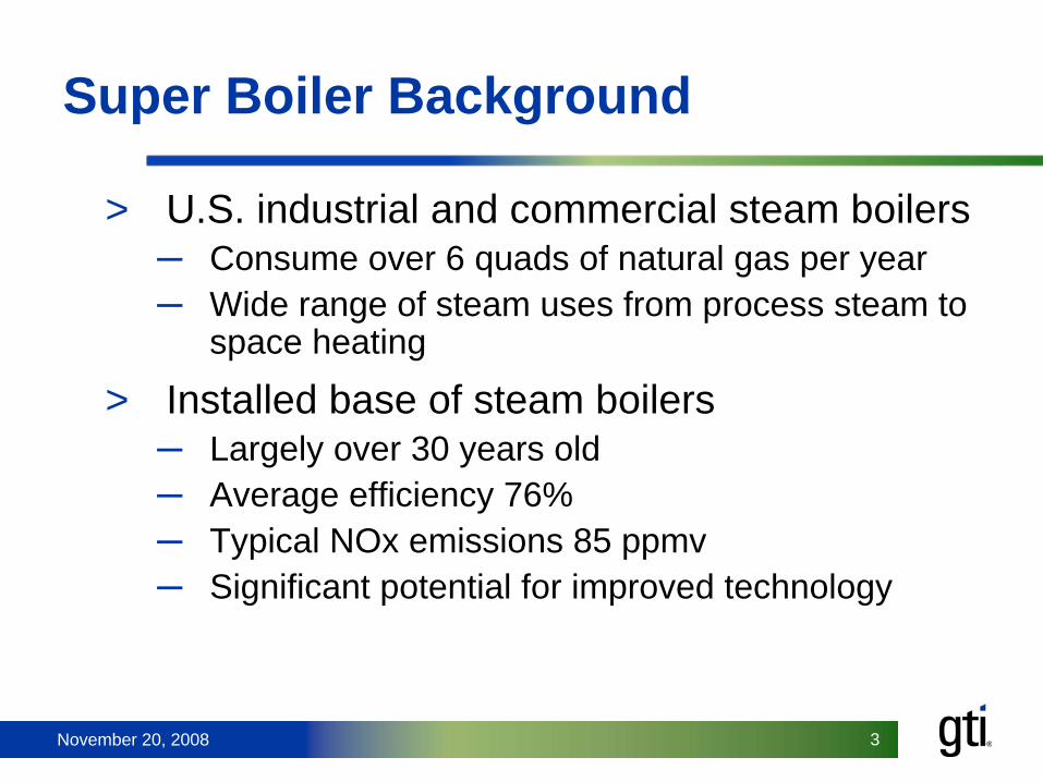
U.S. industrial and commercial steam boilers─
Consume over 6 quads of natural gas per year
─
Wide range of steam uses from process steam to space heating
>
Installed base of steam boilers─
Largely over 30 years old
─
Average efficiency 76%─
Typical NOx emissions 85 ppmv
─
Significant potential for improved technology

November 20, 2008 4November 20, 2008 4
Project Origin & Goals
>
Super Boiler program─
Started by DOE and gas industry in 1999
─
GTI team selected to carry out project
>
Goals: ─
Maximum efficiency
─
NOx and CO less than 5 ppmv ─
Reduced footprint and weight
─
Cost-effectiveness

November 20, 2008 5November 20, 2008 5
COMBUSTION
Natural gas combustion produces heat for steam generation, but also unwanted emissions (NOx, CO, VOC, PM)Combustion at lower excess air improves energy efficiency Minimizing NOx while achieving complete fuel burnout at low excess air was a huge challenge

November 20, 2008 6November 20, 2008 6
Combustion: parallel approaches
>
Single-stage─
Commercially available NatCom burner
─
Internal staging and FGR
>
Two-stage─
Extension of GTI’s FIR burner technology
─
Staged premixed combustion with inter-stage heat removal
─
No FGR required─
Requires special boiler design

November 20, 2008 7November 20, 2008 7
Combustion: single-stage controls
>
Operator interface via Hawk ICS touchscreen PLC control panel
>
PLC control─
Fuel/air ratio control via individual drive motors with VFD trim
─
FGR damper control from individual controller─
O2
trim managed by in-situ O2
sensor─
Separate combustion setups for heat recovery and bypass modes

November 20, 2008 8
Combustion: two-stage version*
>
80 HP lab boiler─
Staged burner with internal recirculation
─
Interstage cooling pass─
No FGR required
─
3-5 ppmv NOx at 1-2% O2
FUEL
FUEL-AIR MIXER
PRIMARY AIR
SECONDARY AIR
FUEL-AIR MIXER
* U.S. Patent No. 6,289,851 (Sept 2001), U.S. Patent No. 6,971,336 B1 (Dec. 2005)

November 20, 2008 9November 20, 2008 9
Combustion: two-stage field demo
>
300 HP field demonstration─
Clement Pappas & Co. (Ontario CA)
─
Juice and beverage bottler─
Steam used for pasteur-
ization and cleaning─
Steam demand = zero to 9,500 lb/h, highly variable
─
Scale-up included integral head design
─
Operates year-round 24/7─
Started testing Feb 2008

November 20, 2008 10November 20, 2008 10
Combustion: two-stage controls
>
Operator interface via Hawk ICS touchscreen PLC control panel
>
PLC control─
Critical first stage fuel/air ratio control via fuel delta-P and windbox air delta-P
─
Control implemented via parallel positioning (PP) controllers with VFD trim
─
O2
trim integrated into air split management─
Separate setups for heat recovery and bypass modes

November 20, 2008 11November 20, 2008 11
Heat Transfer: convective pass
>
Enhanced firetube heat transfer─
Fire-tubes with extruded aluminum inserts
─
Heat transfer 18X higher than conventional tubes─
2-pass boiler can deliver 4-pass performance with a smaller footprint
RIFLED TUBES
CLEAVER-BROOKS TUBE INSERTS

November 20, 2008 12November 20, 2008 12
Heat Transfer: field demonstrations
>
300 HP field demonstration─
Both AL and CA demos use finned firetube inserts in two-
pass design─
Flue gas cooled to 35°F above steam temperature
─
California Super Boiler: 38% lighter & 31% smaller footprint
than conventional 300 HP boiler
Standard CB 300HP boiler123 sq ft
300HP Super Boiler85 sq ft

November 20, 2008 13November 20, 2008 13
HEAT RECOVERY
Natural gas combustion produces about 18% water from oxidation of H in fuelWater vapor up the stack accounts for 10% of fuel energy input, or 65% of stack lossKey to higher energy efficiency is to recover both sensible and latent heat

November 20, 2008 14November 20, 2008 14
Heat Recovery: general approach
>
Flue gas heat recovery─
Remove sensible heat with two economizers
─
Remove latent heat with Transport Membrane Condenser (TMC)
─
Suitable for end users with high make-up water usage
Fuel in
Steam Out
Boiler
Deaerator/ Make-Up
Tank
Ambient air
LPEHPE
Flue gas out
TMC
Make-up water
BFW

November 20, 2008 15November 20, 2008 15
Heat Recovery: TMC concept*
>
Transport Membrane Condenser (TMC)─
Nanoporous ceramic membrane tubes
─
Water vapor permeation via capillary condensation
─
Partial vacuum on shell side
─
Counter-flow configuration
Warm humid flue
gas in
Warm water out to
deaerator
Cool feed water
in
Cool dry flue
gas out
* U.S. Patent No. 6,517,607, 2008 Chicago Innovation Award

November 20, 2008 16November 20, 2008 16
Preheated humidified air
Heat Recovery: expanded system*
>
Applications with high condensate return─
Limited make-up water reduces TMC capacity
─
Recycle water through humidifying air heater (HAH)
─
Air humidification helps suppress NOx
Fuel in
Steam Out
Boiler
Deaerator/ Make-Up
Tank
Ambient air
LPEHPE
Make-up water
Flue gas out
TMCHAH
Condensate return
BFW
*U.S. Patent No. 7,066,396

November 20, 2008 17November 20, 2008 17
Heat Recovery: Alabama field demo

November 20, 2008 18November 20, 2008 18
Heat Recovery: Alabama field demo

November 20, 2008 19November 20, 2008 19
Heat Recovery: TMC hardware
>
Down-flow “Version 1.0”─
Cylindrical shell design
─
Tube bundles (17”
x 4”), 99 tubes/bundle
─
Water on shell side with bottom inlet for natural counter-flow
─
Flue gas cooled to <160°F─
Shell-side vacuum 3 psid
─
Flue gas pressure drop <4 in WC
TMC (3 MMBtu/h)
TMC (11 MMBtu/h)

November 20, 2008 20November 20, 2008 20
Heat Recovery: California field demo
>
Clement Pappas & Co. in Ontario CA─
Heat recovery system (HRS) similar to Alabama site
─
HRS mounted above boiler

November 20, 2008 21November 20, 2008 21
1st and 2nd Generation Membrane Bundles

November 20, 2008 22
TMC Version 2.1 in Duct
Warm water to deaerator
Cool feed water in
Warm moist flue
gas in
Cooler Dryer flue gas out

November 20, 2008 23November 20, 2008 23
Heat Recovery: improved TMC design
>
Upflow “Version 2.0”─
Modular design
─
25-HP tube bundle modules─
Water inside tubes with staged downward flow
─
Above-boiler mounting─
Easier assembly and service
─
More compact─
Less ductwork

November 20, 2008 24November 20, 2008 24
Heat Recovery: Utah field demo
>
Retrofit of Existing 200 hp 150 Psig Firetube Boiler─
TMC “Version 2.0”
retrofit to
standard 200 HP CB boiler─
No condensate return/ no HAH
─
Low-cost integrated LPE panel
─
Integrated boiler/HR controls

November 20, 2008 25November 20, 2008 25
Latest Improvements
>
TMC Version 2.1─
CFD modeling and full-scale lab tests revealed ability to reduce passes from 4 to 3
─
25% savings in number of modules─
TMC module capacity increased to 33 HP
>
Air heater─
Field data showed that HAH efficiency results could be achieved with non-humidifying air heater
─
80% lower capital cost─
Simpler controls

November 20, 2008 26November 20, 2008 26
Proposed Heat Recovery Retrofit for 250 hp 150 psig CB Boiler
> Schematic

November 20, 2008 27November 20, 2008 27
Required Support Equipment
>
Makeup tank/ deaerator─
Receives hot water from LPE
─
Two-stage level control─
Need stable inputs (MUW, condensate return)
>
Softened or de-mineralized water>
Water filter for TMC
>
Structural supports/access platforms as needed
November 20, 2008 28
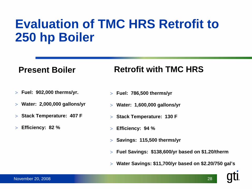
Evaluation of TMC HRS Retrofit to 250 hp Boiler
>
Fuel: 902,000 therms/yr.
>
Water: 2,000,000 gallons/yr
>
Stack Temperature: 407 F
>
Efficiency: 82 %
>
Fuel: 786,500 therms/yr
>
Water: 1,600,000 gallons/yr
>
Stack Temperature: 130 F
>
Efficiency: 94 %
>
Savings: 115,500 therms/yr
>
Fuel Savings: $138,600/yr based on $1.20/therm
>
Water Savings: $11,700/yr based on $2.20/750 gal’s
Present Boiler Retrofit with TMC HRS

November 20, 2008 29November 20, 2008 29
>Dennis Chojnacki
(847-768-0710)>[email protected]
>Curt Bermel
(847-768-0649)>[email protected]
GTI Contact Information


