
STRENGTH OF MATERIALS TEXTBOOK
ILLUSTRATIVE MATERIAL
DOLGOV A.M.
Dnepropetrovsk - 2015
MINISTRY OF EDUCATION AND SCIENCE OF UKRAINE STATE HIGHER EDUCATIONAL INSTITUTION
«NATIONAL MINING UNIVERSITY» DEPARTMENT OF STRUCTURAL THEORETICAL AND APPLIED
MECHANICS

1
2
3
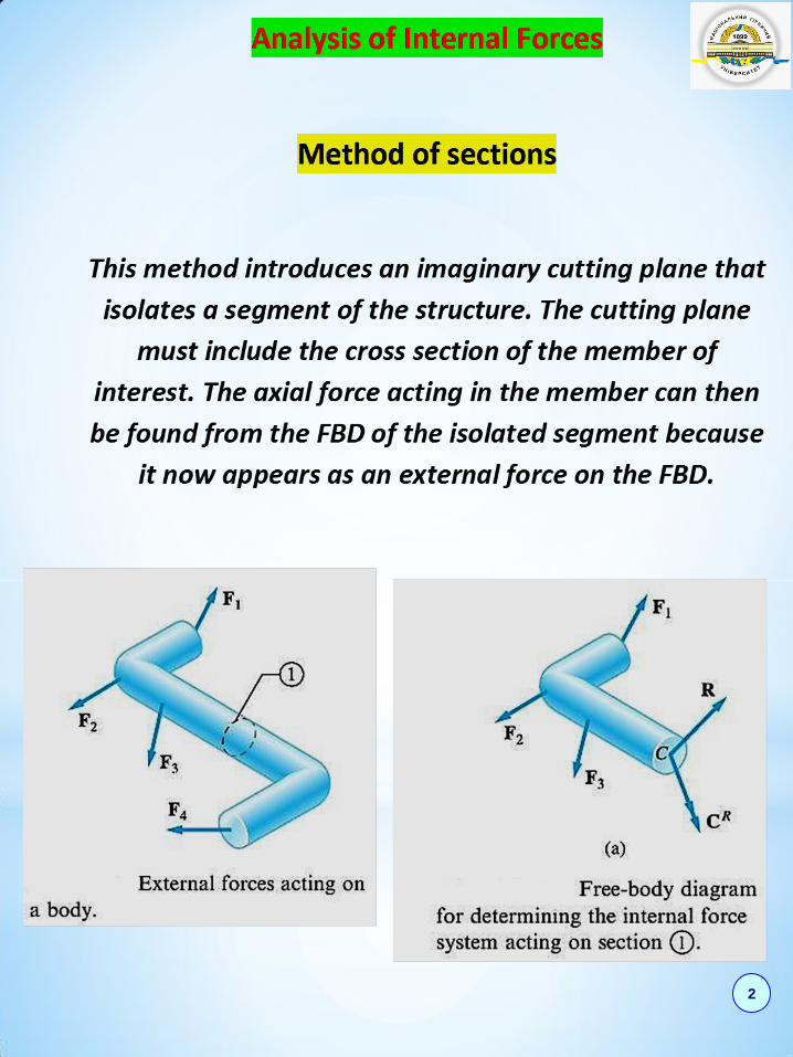
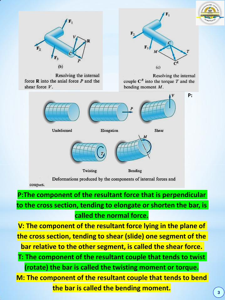
P:The component of the resultant force that is perpendicular
to the cross section, tending to elongate or shorten the bar, is
called the normal force.
V: The component of the resultant force lying in the plane of
the cross section, tending to shear (slide) one segment of the
bar relative to the other segment, is called the shear force.
T: The component of the resultant couple that tends to twist
(rotate) the bar is called the twisting moment or torque.
M: The component of the resultant couple that tends to bend
the bar is called the bending moment.

4
5

6

7
8
9

10

11
12

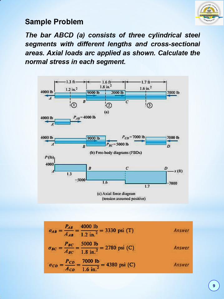
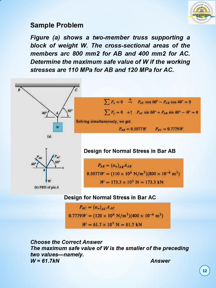
Sample Problem
The rectangular wood panel is formed by gluing
together two boards along the 30-degree scam.
Determine the largest axial force P that can be carried
safely by the panel if the working stress for the wood
is 1120 psi and the normal and shear stresses in the
glue are limited to 700 psi and 450 psi respectively.
Design for Working Stress in Wood
Design for Normal Stress in Glue
Design for Shear Stress in Glue
Choose the Correct Answer
Comparing the above three solutions, we see that the
largest safe axial load that can be safely applied is
governed by the normal stress in the glue, its value
being P = 3730 lb Answer 13
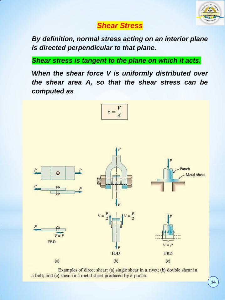
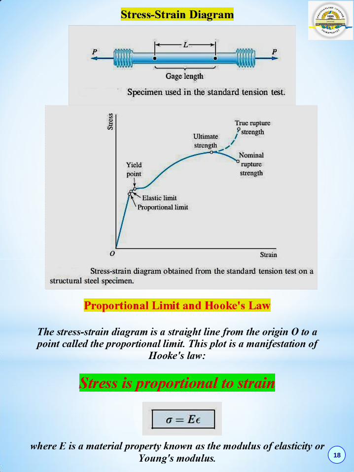
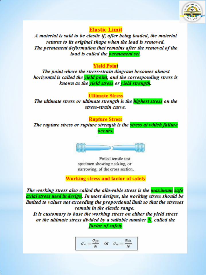
Shear Stress
By definition, normal stress acting on an interior plane
is directed perpendicular to that plane.
Shear stress is tangent to the plane on which it acts.
When the shear force V is uniformly distributed over
the shear area A, so that the shear stress can be
computed as
14
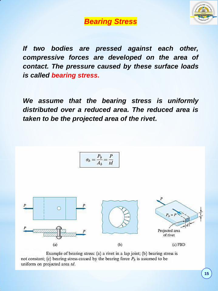
Bearing Stress
If two bodies are pressed against each other,
compressive forces are developed on the area of
contact. The pressure caused by these surface loads
is called bearing stress.
We assume that the bearing stress is uniformly
distributed over a reduced area. The reduced area is
taken to be the projected area of the rivet.
15
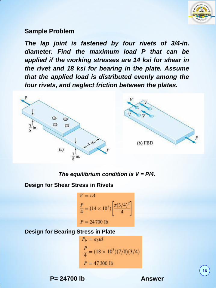
Sample Problem
The lap joint is fastened by four rivets of 3/4-in.
diameter. Find the maximum load P that can be
applied if the working stresses are 14 ksi for shear in
the rivet and 18 ksi for bearing in the plate. Assume
that the applied load is distributed evenly among the
four rivets, and neglect friction between the plates.
The equilibrium condition is V = P/4.
Design for Shear Stress in Rivets
Design for Bearing Stress in Plate
P= 24700 lb Answer
16
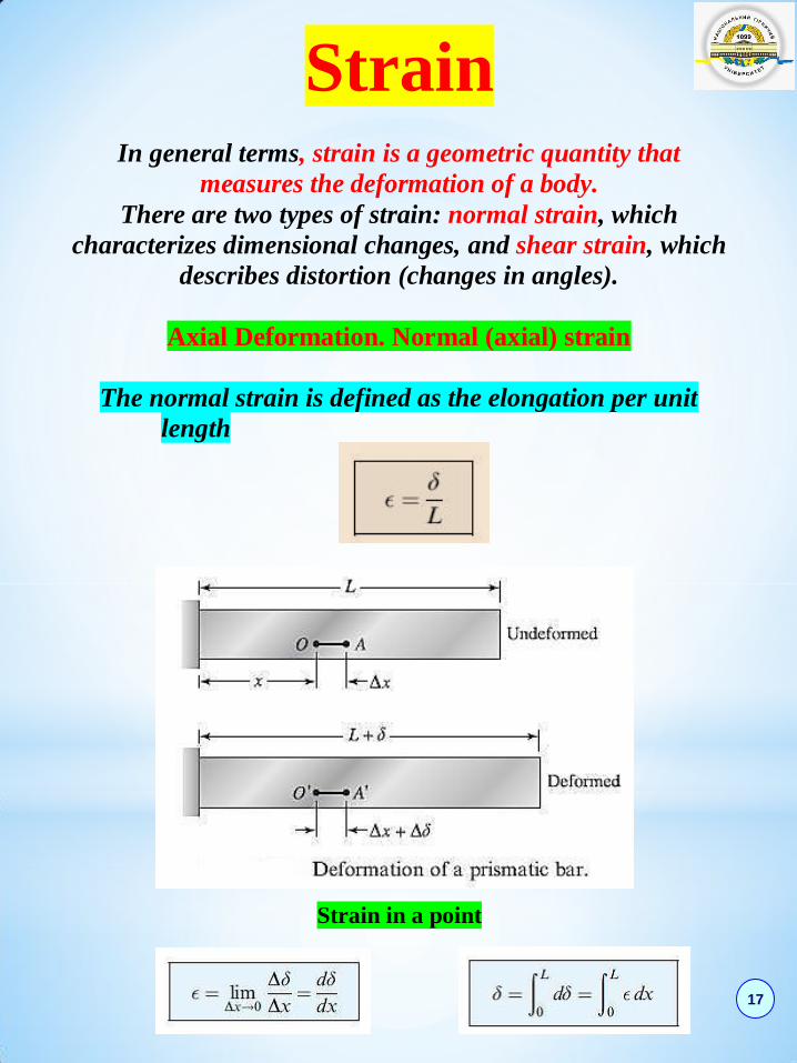
Strain
In general terms, strain is a geometric quantity that
measures the deformation of a body.
There are two types of strain: normal strain, which
characterizes dimensional changes, and shear strain, which
describes distortion (changes in angles).
Axial Deformation. Normal (axial) strain
The normal strain is defined as the elongation per unit
length
Strain in a point
17
18
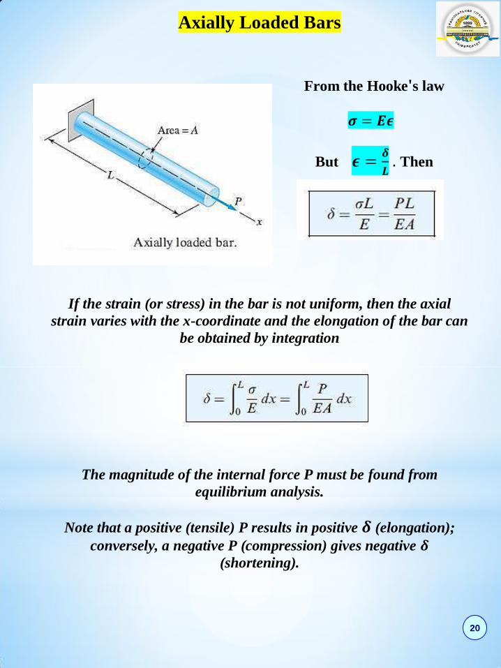
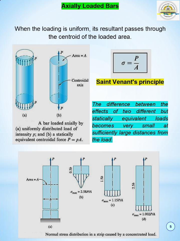
Axially Loaded Bars
From the Hooke's law
𝝈 = 𝑬𝝐
But 𝝐 =𝜹
𝑳 . Then
If the strain (or stress) in the bar is not uniform, then the axial
strain varies with the x-coordinate and the elongation of the bar can
be obtained by integration
The magnitude of the internal force P must be found from
equilibrium analysis.
Note that a positive (tensile) P results in positive 𝜹 (elongation);
conversely, a negative P (compression) gives negative 𝜹
(shortening).
20

Sample Problem
The steel propeller shaft ABCD carries the axial loads shown in
Fig. Determine the change in the length of the shaft caused by these
loads. Use 𝑬 = 𝟐𝟗 × 𝟏𝟎𝟔psi for steel.
21
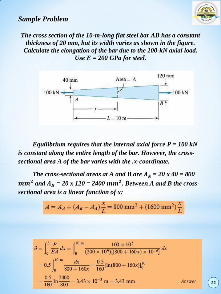
Sample Problem
The cross section of the 10-m-long flat steel bar AB has a constant
thickness of 20 mm, but its width varies as shown in the figure.
Calculate the elongation of the bar due to the 100-kN axial load.
Use E = 200 GPa for steel.
Equilibrium requires that the internal axial force P = 100 kN
is constant along the entire length of the bar. However, the cross-
sectional area A of the bar varies with the .x-coordinate.
The cross-sectional areas at A and B are 𝑨𝑨 = 20 x 40 = 800
𝒎𝒎𝟐 and 𝑨𝑩 = 20 x 120 = 2400 𝒎𝒎𝟐. Between A and B the cross-
sectional area is a linear function of x:
22

Sample Problem
The rigid bar AC is supported by the steel rod AC of cross-sectional
area 0.25 𝒊𝒏𝟐. Find the vertical displacement of point C caused by the
2000-lb load. Use E= 29 x 𝟏𝟎𝟔 psi for steel.
The geometric relationship between
𝜹𝑨𝑪 and the displacement ∆𝑪 of C is
illustrated in the displacement diagram.
23
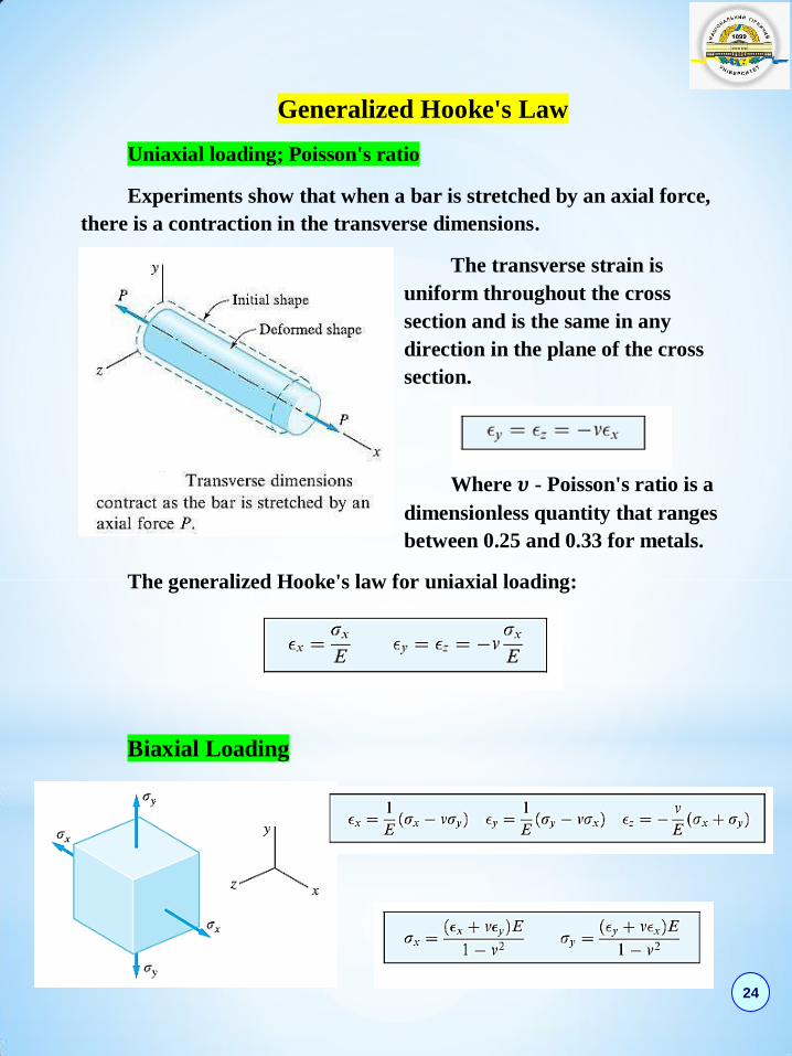
Generalized Hooke's Law
Uniaxial loading; Poisson's ratio
Experiments show that when a bar is stretched by an axial force,
there is a contraction in the transverse dimensions.
The transverse strain is
uniform throughout the cross
section and is the same in any
direction in the plane of the cross
section.
Where 𝝊 - Poisson's ratio is a
dimensionless quantity that ranges
between 0.25 and 0.33 for metals.
The generalized Hooke's law for uniaxial loading:
Biaxial Loading
24

Triaxial Loading
Shear loading
Shear stress causes the deformation shown in Fig. The lengths of
the sides of the element do not change, but the element undergoes
a distortion from a rectangle to a parallelogram. The shear strain,
which measures the amount of distortion, is the angle 𝜸. It can be
shown that the relationship between shear stress 𝝉 and shear
strain 𝜸 is linear within the elastic range, that is,
which is Hooke's law for shear.
The material constant G is
called the shear modulus of
elasticity (or simply shear
modulus), or the modulus of
rigidity.
25
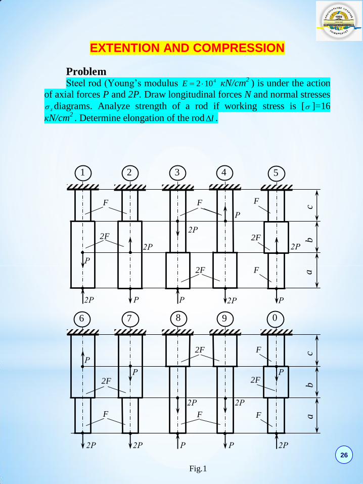
EXTENTION AND COMPRESSION
Problem Steel rod (Young’s modulus 4102 E кN/cm
2 ) is under the action
of axial forces P and 2P. Draw longitudinal forces N and normal stresses
z diagrams. Analyze strength of a rod if working stress is [ ]=16
кN/cm2 . Determine elongation of the rod l .
Fig.1
F
Р
Р Р
Р
2Р 2Р 2Р
2Р 2Р
2F
F
Р
2F F
2F
F
c b
a
3 4 5
2Р 2Р
2Р 2Р
2Р
Р
Р Р Р
Р
2F
2F
2F
F
F F F c b
a
1 2
6 7 8 9 0
26
DATA
№ F, cm2 a, m b, m c, m P, кN
1 2,0 1,2 1,4 1,6 11
2 2,2 1,4 1,6 1,4 12
3 2,4 1,8 1,6 1,2 13
4 2,6 1,6 2,0 1,0 14
5 2,8 2,0 1,8 1,2 15
6 3,0 2,2 1,6 1,4 16
7 3,2 2,4 1,4 1,6 17
8 3,4 2,6 1,2 1,8 18
9 3,6 2,8 1,0 1,4 19
10 3,8 2,4 1,6 1,2 20
11 2,2 1,6 1,4 1,2 10
12 2,4 1,6 1,8 1,0 11
13 2,6 2,0 1,8 1,0 13
14 2,8 1,8 2,0 1,4 14
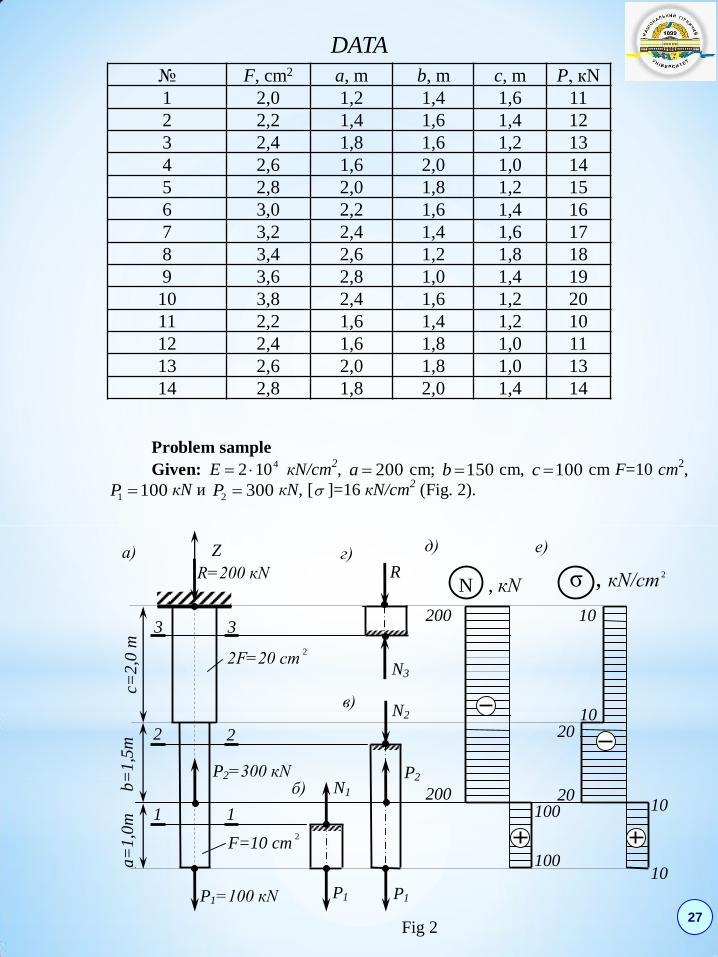
Problem sample
Given: 4102 E кN/cm2, 200a cm; 150b cm, 100c cm F=10 cm
2,
1001 P кN и 3002 P кN, [ ]=16 кN/cm2 (Fig. 2).
Fig 2
a=
1,0
m
b=
1,5
m
c=2
,0 m
200
F=10 cm2
10
10
R=200 кN
б)
в)
3 3
1
2 2
1
P2=300 кN
P1=100 кN
а)
2F=20 сm2
N1
P1
N2
г)
N3
200
R
P1
P2
100
100
10
10 20
20
д)
е)
N , кN σ , кN/cm 2
Z
27

Solution.
1. Define reaction R in rigid clamp.
0Z : 200100300;0 1212 PPRPPR кN.
2. Draw N diagram.
10011 PN кN.
200100300122 PPN кN.
2003 RN кN.
3. Draw z diagram.
kkz FNk ,
1010
1001
1
1
1
F
N
F
Nz кN/cm
2,
2010
2002
2
2
2
F
N
F
Nz кN/cm
2,
1020
200
2
3
3
3
3
F
N
F
Nz кN/cm
2.
4. Analyze strength of the rod.
Strength condition is max
z . In our case
202
max zz кN/cm2 > 16 кN/cm
2,
Then the area of the second segment is to be increased: [ ] 512=16200=22 ,NF σ≥ cm
2.
Take on a second segment 5,122 F cm2.
5. Calculate elongation of the rod l .
k k
kk
EF
lNl ,
17,020102
200200
5,12102
150200
10102
100100444
3
33
2
22
1
11
EF
lN
EF
lN
EF
lNl см.
Hence, the length of the rod decreases 7,1 мм.
___________________
28

29
Properties of Plane Areas
First Moments of Area; Centroid The first moments of a plane area A about the x- and y-axes are defined as
,where dA is an
infinitesimal element of A located at (x,y), as
shown in Fig.
The centroid C of the area is defined as the point in the xy-plane that has the coordinates
.
The following are useful properties of the first moments of area:
.If the origin of the xy-coordinate system is the centroid of the area (in
which case ), then
.Whenever the area has an axis of symmetry, the centroid of the area will
lie on that axis.
Second Moments of Area
We define the second moments of a plane area A with respect to the xy-axes by
.
The integrals Ix and Iy are commonly called the moments of inertia, whereas Ixy is known as the product of inertia.

30
We define the polar moment of inertia of an area about point O (strictly speaking, about an axis through O, perpendicular to the plane of the area) by
. where r is the distance from O to the area element dA. The polar moment of inertia of an area about a point O equals the sum of the moments of inertia of the area about two perpendicular axes that intersect at O.
Parallel-Axis Theorems
The parallel-axis theorem for the moment of inertia of an area
The parallel-axis theorem for
products of inertia
The parallel-axis theorem for the polar moment of inertia
31
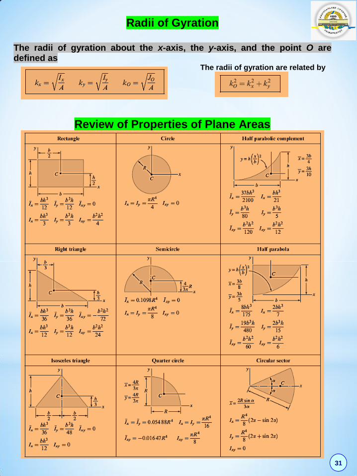
Radii of Gyration
The radii of gyration about the x-axis, the y-axis, and the point O are defined as
The radii of gyration are related by
Review of Properties of Plane Areas
32
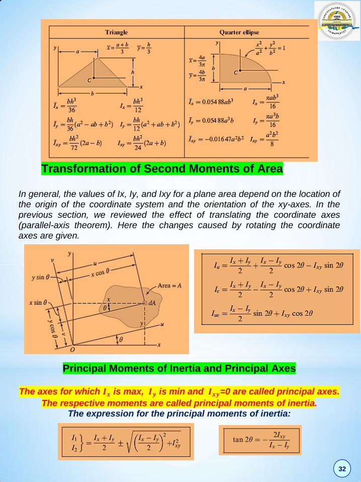
Transformation of Second Moments of Area
In general, the values of Ix, Iy, and Ixy for a plane area depend on the location of the origin of the coordinate system and the orientation of the xy-axes. In the previous section, we reviewed the effect of translating the coordinate axes (parallel-axis theorem). Here the changes caused by rotating the coordinate axes are given.
Principal Moments of Inertia and Principal Axes
The axes for which 𝑰𝒙 is max, 𝑰𝒚 is min and 𝑰𝒙𝒚=0 are called principal axes.
The respective moments are called principal moments of inertia. The expression for the principal moments of inertia:
33

34
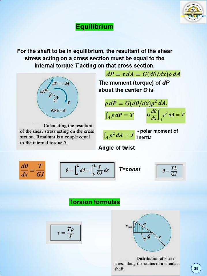
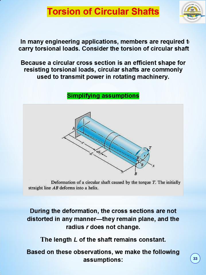
35
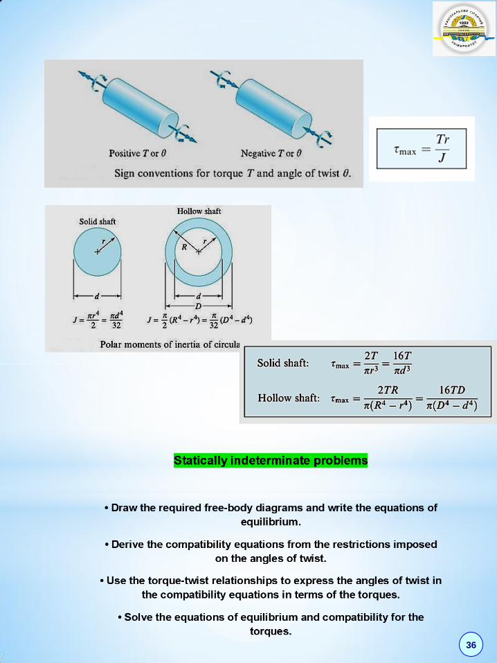
36
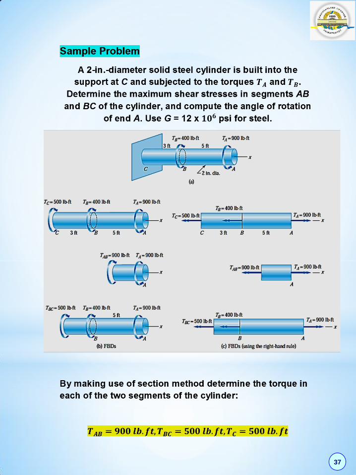
37

The rotation of end A of the cylinder is obtained by
summing the angles of twist of the two segments:
The positive result indicates that the rotation vector of A is
in the positive .x-direction: that is, 𝜽𝑨 is directed
counterclockwise when viewed from A toward C.
38
39

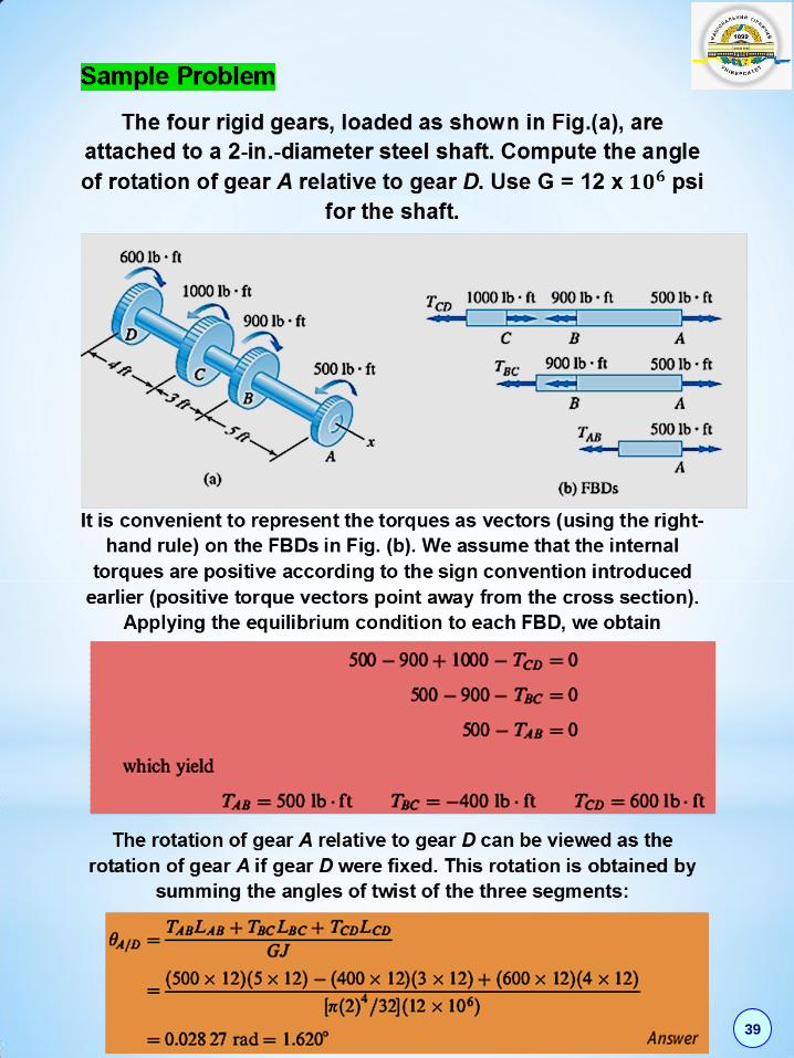
Sample Problem
A solid steel shaft in a rolling mill transmits 20 kW of power
at 2 Hz. Determine the smallest safe diameter of the shaft if
the shear stress is not to exceed 40 MPa and the angle of
twist is limited to 𝟔°in a length of 3 m. Use G = 83 GPa.
This problem illustrates a design that must possess
sufficient strength as well as rigidity.
Determine the torque:
Satisfy the strength condition:
Satisfy the requirement of rigidity:
To satisfy both strength and rigidity requirements, we
must choose the larger diameter namely,
40
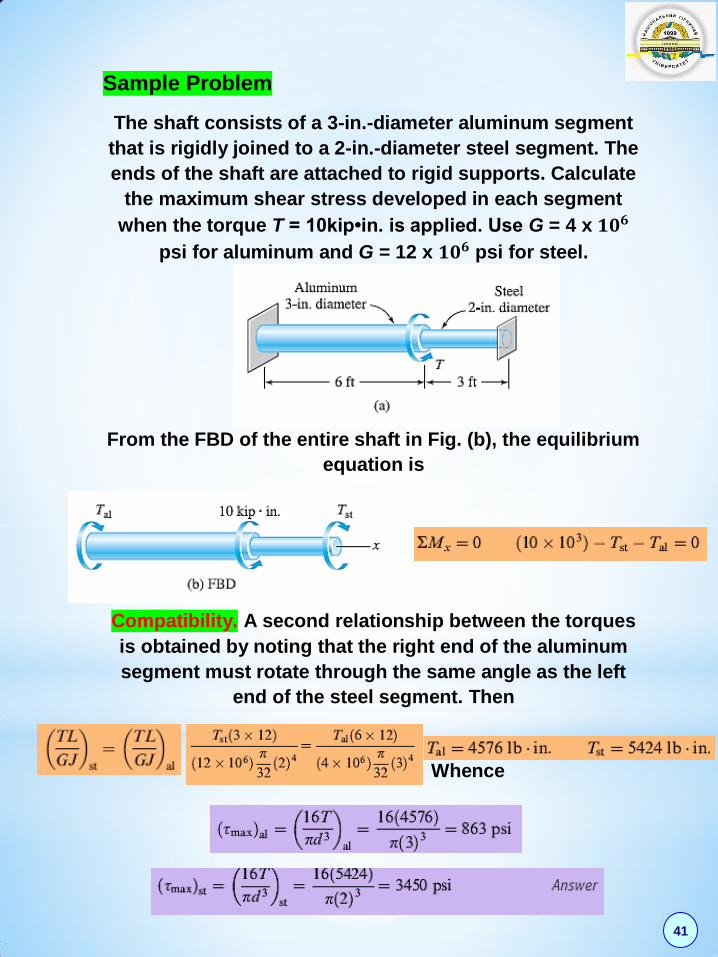
Sample Problem
The shaft consists of a 3-in.-diameter aluminum segment
that is rigidly joined to a 2-in.-diameter steel segment. The
ends of the shaft are attached to rigid supports. Calculate
the maximum shear stress developed in each segment
when the torque T = 10kip•in. is applied. Use G = 4 x 𝟏𝟎𝟔
psi for aluminum and G = 12 x 𝟏𝟎𝟔 psi for steel.
From the FBD of the entire shaft in Fig. (b), the equilibrium
equation is
Compatibility. A second relationship between the torques
is obtained by noting that the right end of the aluminum
segment must rotate through the same angle as the left
end of the steel segment. Then
Whence
41

TORTION OF CIRCULAR SHAFTS Problem Steel circular shaft (shear module 4108,0 G кN/cm
2) is loaded by
4 torques iM (Fig. 1). (1) Draw torque diagram; (2) Define safe
diameters of the shaft at 8 кN/cm2; (3) Draw twist angle diagram.
Fig.1
М1 М2 М3 М4
М1 М2 М3 М4
М1 М2 М3 М4 М1 М2 М3
М3
М3
М4 М1 М2
М4 М1 М2
М4
6
8
0
7
9
5
a b c d a b c d
М1 М2 М3 М4
М1 М2 М3 М4 М3
М3 М1 М2 М4
М4 М1 М2
4
1
3
2
№ М1,
кN·м
М2,
кN·м
М3,
кN·м
М4,
кN·м
a,
м
b,
м
c,
м
d,
м
1 1,0 2,0 1,0 1,0 1,0 1,2 1,4 1,6
2 1,0 2,0 1,0 0,8 1,2 1,4 1,6 1,9
3 2,0 4,0 1,0 1,0 1,4 1,6 1,0 1,2
4 3,0 5,0 1,6 1,4 1,6 1,0 1,2 1,4
5 4,0 6,0 1,8 1,4 1,1 1,1 1,8 1,5
6 2,0 4,0 1,2 1,2 1,3 1,3 1,5 1,1
7 2,0 3,0 1,2 1,0 1,5 1,5 1,3 1,3
8 3,0 4,0 1,0 1,0 1,7 1,7 1,5 1,4
9 4,0 5,0 1,8 1,6 1,9 1,9 1,7 1,3
0 5,0 6,0 2,0 1,6 1,2 1,4 1,4 1,2 42

43

For section 1 – 1: 8,141 MM z кN·м.
By analogy for sections 2 – 2 и 3 – 3:
0,52,38,1342 MMM z
кN·м;
5,05,52,38,12343 MMMM z кN·м.
24
Az MM кN·м.
3. Determine diameter of the shaft from strength condition.
W
M z maxmax ,
where 33 2,016 ddW -section modulus.
5002max zz MM кN·сm.
Then
2
3 3500
6,790,2 0,2 8
zMd
сm.
Rounding we have 70d мм.
4. Calculate angles of twist and draw twist angles diagram. 44 1,032 ddI
444 1019271,0108,0 GI кN·сm2.
0156,010192
1502004
4
GI
aM z
AB rad;
0052,010192
200504
3
GI
bM z
BС rad;
0260,010192
1005004
2
GI
cM z
CD rad;
0113,010192
1201804
1
GI
dM z
DE rad.
0A .
0156,00156,00 ABAB rad;
0208,00052,00156,0 BCBC rad;
0052,00260,00208,0 CDCD rad;
0165,00113,00052,0 DEDE rad.
_______________________
44
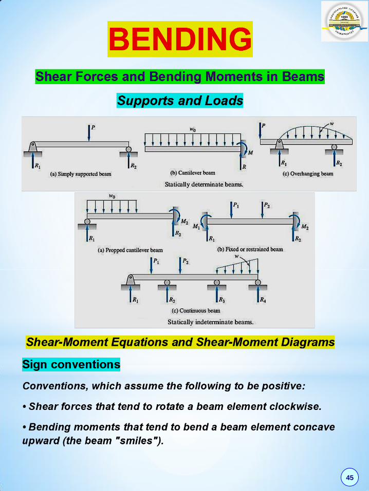
45

Procedure for determining shear force and
bending moment diagrams:
• Compute the support reactions from the FBD of the
entire beam.
• Divide the beam into segments so that the loading
within each segment is continuous.
Perform the following steps for each segment of the
beam:
• Introduce an imaginary cutting plane within the
segment, located at a distance x from either end of the
beam, that cuts the beam into two parts.
• Draw a FBD for the part of the beam lying either to the
left or to the right of the cutting plane, whichever is
more convenient.
• Determine the expressions for V and M from the
equilibrium equations obtainable from the FBD.
• Plot the expressions for V and M for the segment.
46

47
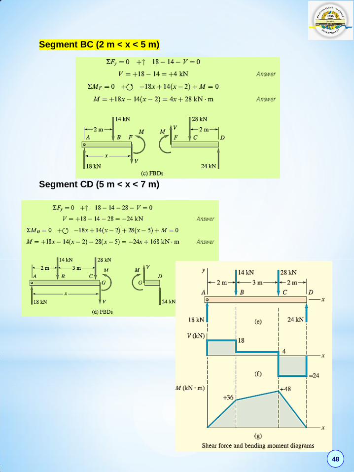
Segment BC (2 m < x < 5 m)
Segment CD (5 m < x < 7 m)
48

Sample Problem
The simply supported beam in Fig (a) is loaded by the
clockwise couple 𝑪𝟎 at B. (1) Derive the shear force and
bending moment equations, and (2) draw the shear force and
bending moment diagrams. Neglect the weight of the beam.
The support reactions A and C have been computed, and their
values are shown in Fig. (a).
Segment AB (0 < x <𝟑
𝟒𝐋) Segment BC (3L/4 < x < L)
49

Sample Problem
The cantilever beam in Fig (a) carries a triangular load, the
intensity of which varies from zero at the left end to 360 lb/ft at
the right end. In addition, a 1000-lb upward vertical load acts at
the free end of the beam. (1) Derive the shear force and
bending moment equations, and (2) draw the shear force and
bending moment diagrams. Neglect the weight of the beam.
50

51
52
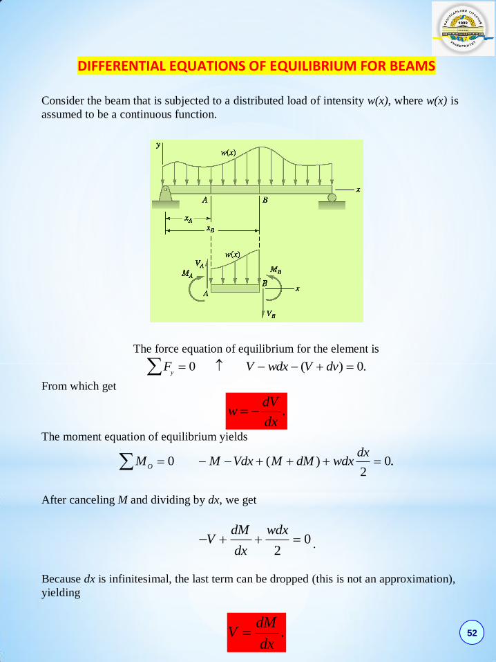
DIFFERENTIAL EQUATIONS OF EQUILIBRIUM FOR BEAMS
Consider the beam that is subjected to a distributed load of intensity w(x), where w(x) is
assumed to be a continuous function.
The force equation of equilibrium for the element is
0 ( ) 0.y
F V wdx V dv
From which get
.dV
wdx
The moment equation of equilibrium yields
0 ( ) 02
.O
dxM M Vdx M dM wdx
After canceling M and dividing by dx, we get
02
dM wdxV
dx .
Because dx is infinitesimal, the last term can be dropped (this is not an approximation),
yielding
.dM
Vdx
53
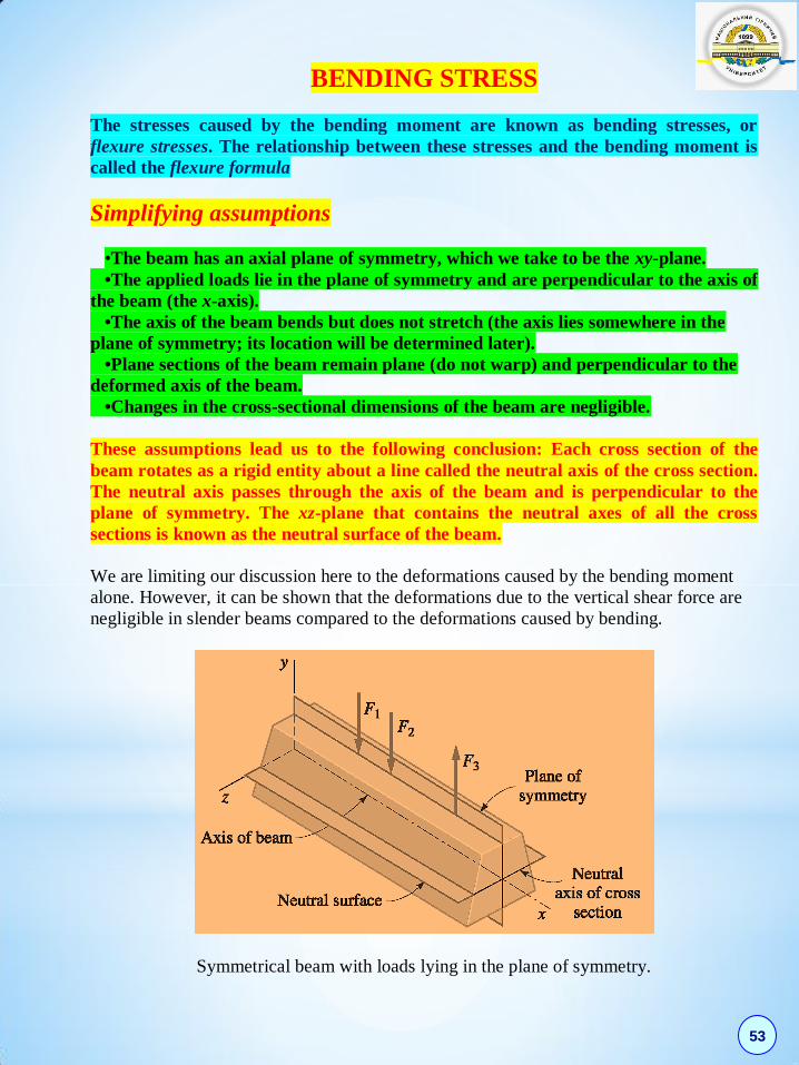
BENDING STRESS
The stresses caused by the bending moment are known as bending stresses, or
flexure stresses. The relationship between these stresses and the bending moment is
called the flexure formula
Simplifying assumptions
•The beam has an axial plane of symmetry, which we take to be the xy-plane.
•The applied loads lie in the plane of symmetry and are perpendicular to the axis of
the beam (the x-axis).
•The axis of the beam bends but does not stretch (the axis lies somewhere in the
plane of symmetry; its location will be determined later).
•Plane sections of the beam remain plane (do not warp) and perpendicular to the
deformed axis of the beam.
•Changes in the cross-sectional dimensions of the beam are negligible.
These assumptions lead us to the following conclusion: Each cross section of the
beam rotates as a rigid entity about a line called the neutral axis of the cross section.
The neutral axis passes through the axis of the beam and is perpendicular to the
plane of symmetry. The xz-plane that contains the neutral axes of all the cross
sections is known as the neutral surface of the beam.
We are limiting our discussion here to the deformations caused by the bending moment
alone. However, it can be shown that the deformations due to the vertical shear force are
negligible in slender beams compared to the deformations caused by bending.
Symmetrical beam with loads lying in the plane of symmetry.

54
Compatibility
A segment of the beam bounded by two cross sections that are separated by the
infinitesimal distance dx.
Deformation of an infinitesimal beam segment.
The distance between the cross sections, measured along the neutral surface, remains
unchanged at dx. The longitudinal fibers lying on the neutral surface are undeformed,
whereas the fibers above the surface are compressed and the fibers below are stretched.
( )a b y d .
The original length of this fiber is ab dx d .
( )a b ab y d d y
ab d
.
From Hooke’s law E
E y
Equilibrium
The normal force acting on the infinitesimal area dA of the cross section is dP dA .
Substituting ( / )E y , we obtain
,
where y is the distance of dA from the neutral axis.
Equilibrium requires that A
ydP M , 0A
ydP and 0AzdP .
EdP ydA

55
Resultant is a couple equal to the internal bending moment M.
Resultant Axial Force Must Vanish
The condition for zero axial force is 0A
A
EzdP yzdA
.
Because / 0E , the last equation can be satisfied only if 0.A
A
EzdP yzdA
Resultant Moment About y-Axis Must Vanish
The integral A
zydA is called the product of inertia of the cross-sectional area.
According to our assumptions, the y-axis is an axis of symmetry for the cross section, in
which case this integral is zero.
Resultant Moment About the Neutral Axis Must Equal M
2 .A A
EydP y dA M
2
Ay dA I is the moment of inertia of the cross-sectional area about the neutral axis
(the z-axis). Hence
EIM
or
1.
M
EI
56
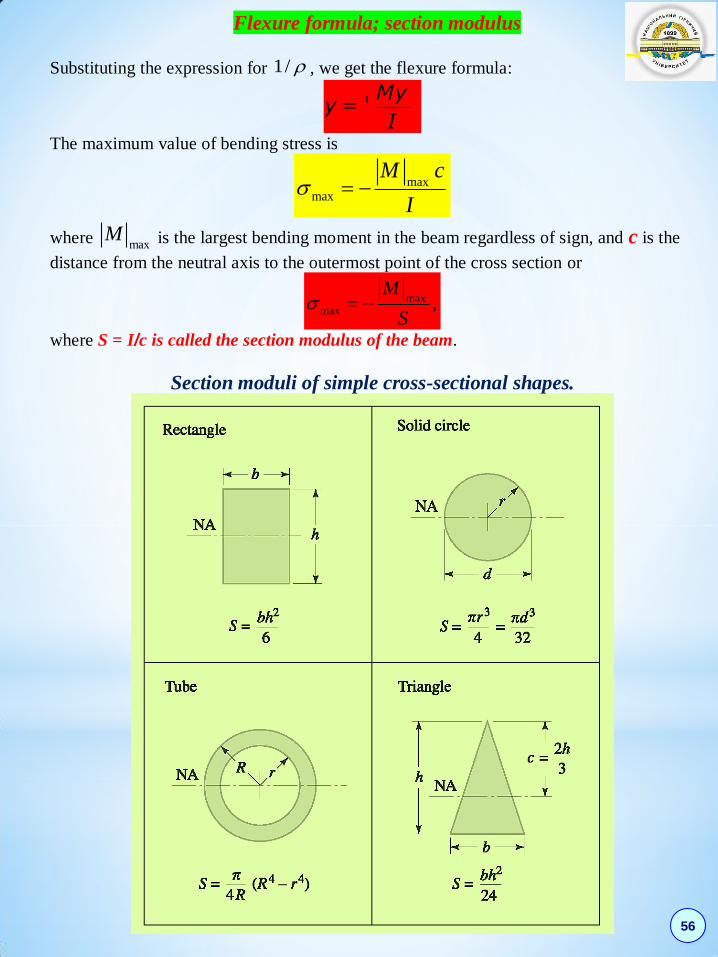
Flexure formula; section modulus
Substituting the expression for 1/ , we get the flexure formula:
Myу =- .
I
The maximum value of bending stress is
maxmax
M c
I
where maxM is the largest bending moment in the beam regardless of sign, and c is the
distance from the neutral axis to the outermost point of the cross section or
maxmax ,
M
S
where S = I/c is called the section modulus of the beam.
Section moduli of simple cross-sectional shapes.

57
Procedures for determining bending stresses
•Use the method of sections to determine the bending moment M (with its correct
sign) at the cross section containing the given point.
•Determine the location of the neutral axis.
•Compute the moment of inertia I of the cross-sectional area about the neutral
axis. ( If the beam is a standard structural shape, its cross- sectional properties are
tabulated.)
• Determine the y-coordinate of the given point.
•Compute the bending stress from /My I . If correct signs are used for M
and y, the stress will also have the correct sign (tension positive, compression
negative).
Maximum Bending Stress: Symmetric Cross Section If the neutral axis is an axis of symmetry of the cross section, the maximum tensile and
compressive bending stresses in the beam are equal in magnitude and occur at the
section of the largest bending moment.
Procedure for determining the maximum bending stress in a prismatic beam
• Draw the bending moment diagram Identify the bending moment maxM .
• Compute the moment of inertia I of the cross-sectional area about the neutral
axis.
• Calculate the maximum bending stress from max max max/ /M c I M S ,
where c is the distance from the neutral axis to the top or bottom of the cross
section.
Procedure for determining Maximum Tensile and Compressive Bending Stressesfor
Unsymmetrical Cross Section
•Draw the bending moment diagram. Identify the largest positive and negative bending moments.
•Determine the location of the neutral axis and record the distances topc and
botc from the neutral axis to the top and bottom of the cross section.
•Compute the moment of inertia I of the cross section about the neutral axis. •Calculate the bending stresses at the top and bottom of the cross section where
the largest positive bending moment occurs from /My I . At the top of the
cross section, where topy c , we obtain /top topMc I . At the bottom of the
cross section, we have boty c , so that /bot botMc I . Repeat the calculations for the cross section that carries the largest negative bending moment. Inspect the four stresses thus computed to determine the largest tensile (positive) and compressive (negative) bending stresses in the beam.
58
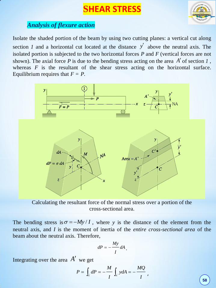
SHEAR STRESS
Analysis of flexure action
Isolate the shaded portion of the beam by using two cutting planes: a vertical cut along
section 1 and a horizontal cut located at the distance y above the neutral axis. The
isolated portion is subjected to the two horizontal forces P and F (vertical forces are not
shown). The axial force P is due to the bending stress acting on the area Aof section 1 ,
whereas F is the resultant of the shear stress acting on the horizontal surface.
Equilibrium requires that F = P.
Calculating the resultant force of the normal stress over a portion of the
cross-sectional area.
The bending stress is /My I , where y is the distance of the element from the
neutral axis, and I is the moment of inertia of the entire cross-sectional area of the
beam about the neutral axis. Therefore,
MydP dA
I .
Integrating over the area A we get
A A
M MQP dP ydA
I I
,

59
where A
Q dA
is the first moment of area A about the neutral axis.
Denoting the distance between the neutral axis and the centroid C of the area A by y
we can write Q A y . Q represents the first moment of the cross-sectional area that
lies above y . Because the first moment of the total cross-sectional area about the
neutral axis is zero, the first moment of the area below y is -Q. The magnitude of Q
can be computed by using the area either above or below y , whichever is more
convenient. The maximum value of Q occurs at the neutral axis where y = 0. It follows
that the horizontal shear force F is largest on the neutral surface.
Horizontal shear stress
Variation of the first moment Q of area Aabout the neutral axis for a
rectangular cross section.
The resultant force acting on face 1 of the body is Q
P MI
.
The bending moment acting at section 2 is M + dM. The resultant normal force acting
on face 2 of the body is
( )Q
P dP m dMI
.
Because these two forces differ by
( ) (M ) ( )Q Q Q
P dP P dM M dMI I I
equilibrium can exist only if there is an equal and opposite shear force dF acting on the
horizontal surface.
If we let be the average shear stress acting on the horizontal surface, its resultant is
dF =фbdx , where b is the width of the cross section at y = y . The equilibrium
requirement for the horizontal forces is
( ) 0.P dP P bdx
60
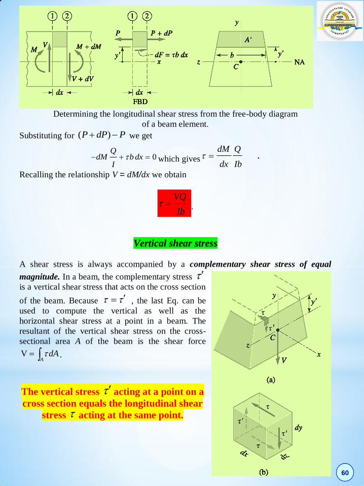
Determining the longitudinal shear stress from the free-body diagram
of a beam element.
Substituting for ( )P dP P we get
0Q
dM b dxI
which gives .dM Q
dx Ib
Recalling the relationship V = dM/dx we obtain
VQ
Ib .
Vertical shear stress
A shear stress is always accompanied by a complementary shear stress of equal
magnitude. In a beam, the complementary stress is a vertical shear stress that acts on the cross section
of the beam. Because , the last Eq. can be
used to compute the vertical as well as the
horizontal shear stress at a point in a beam. The
resultant of the vertical shear stress on the cross-
sectional area A of the beam is the shear force
VA
dA .
The vertical stress acting at a point on a
cross section equals the longitudinal shear
stress acting at the same point.

61
Rectangular and wide-flange sections
The shaded area is ( / 2)A b h y , its centroidal coordinate being ( / 2) / 2y h y .
Thus,
2
21
2 2 2 2 4
h h b hQ A y b y y y
. Then
2
2.
2 4
VQ V hy
Ib I
The shear stress is distributed parabolically across the depth of the section. The
maximum shear stress occurs at
the neutral axis. If we substitute y
= 0 and 3 /12I bh , we obtain
max
3 3
2 2
V V
bh A .
In wide-flange sections, most of the bending moment
is carried by the flanges, whereas the web resists the
bulk of the vertical shear force.
Procedure for analysis of shear stress
•Determine the vertical shear force V acting on the cross section containing the
specified point.
•Locate the neutral axis and compute the moment of inertia I of the cross-sectional
area about the neutral axis.
•Compute the first moment Q of the cross-sectional area that lies above (or below)
the specified point.
•Calculate the shear stress from = VQ/Ib, where b is the width of the cross
section at the specified point. Note that is the actual shear stress only if it is
uniform across b; otherwise, should be viewed as the average shear stress.
The maximum shear stress max on a given cross section occurs where Q=b is
largest. If the width b is constant, then max occurs at the neutral axis because that
is where Q has its maximum value. If b is not constant, it is necessary to compute
the shear stress at more than one point in order to determine its maximum value.

62
COMPLEMENTARY PROBLEMS
For two given schemes of beams is required: • draw the diagrams of shear forces and bending moments; • on the basis of the strength condition by the normal stresses (𝝈𝒘 = 𝟏𝟔 kN кN/cm2), select the beam of the circular cross section for the scheme a, and the I-beam cross-section for the scheme b; • check the strength of the selected beams by shear stresses (𝝉𝒘 = kN/ cm2). Take the data from the following table.
Scheme
number
l,
m
M,
кN·m
P,
кN
q,
кН/m
1 3 0,2 0,6 0,2 8 5 10
2 4 0,3 0,5 0,3 7 6 11
3 5 0,4 0,4 0,3 6 7 12
4 6 0,5 0,3 0,2 5 8 13
5 3 0,6 0,7 0,2 4 9 14
6 4 0,7 0,5 0,3 8 10 9
7 5 0,8 0,4 0,6 7 5 10
8 6 0,2 0,6 0,3 6 6 11
9 3 0,3 0,5 0,4 5 7 12
0 4 0,4 0,4 0,2 4 8 8
la1 la2la3
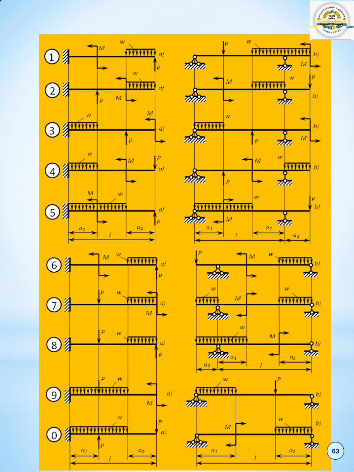
63
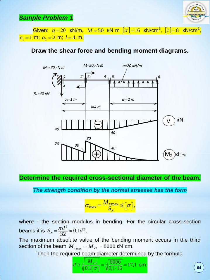
Sample Problem 1
Given: 20q кN/m, 50M кN·m 16 кN/сm2, 8 кN/сm2,
11 a m; 22 a m; 4l m.
Draw the shear force and bending moment diagrams.
Determine the required cross-sectional diameter of the beam.
The strength condition by the normal stresses has the form
maxmax
x
x
MS
,
where - the section modulus in bending. For the circular cross-section
beams it is 3
30,132xd
S d
.
The maximum absolute value of the bending moment occurs in the third
section of the beam 80003max xx MM кN·сm.
Then the required beam diameter determined by the formula
33 3
800017,1
0,1 160,1xM
d
сm.
1 2 3 4 6
М=50 кN∙m q=20 кN/m
a1=1 m a2=2 m
l=4 m
МА=70 кN∙m
RА=40 кN
40
40
80
40
70 30
V кN
МX кН∙м
5
А
64
Take 170d mm. Then
maxmax 3
800016,6
17
32
x
x
M
S
кN/сm2 16 кN/сm2.
The overstrain is %5%75,3%10016
166,16
, which is allowed.
Check the strength of the beam by the maximum shear stresses.
max
max
4
3yV
A ,
where 2 4A d .
The maximum absolute value of the shear force is 1 5max 40y yV V
кN.
Therefore
maxmax 2
4 4 400,235
3 173
4
yV
A
кN/сm2 8 кN/сm2.
The strength condition by shear stress is satisfied.
65
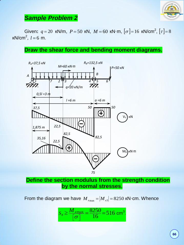
Sample Problem 2 Given: 20q кN/m, 50P кN, 60M кN·m, 16 кN/сm2, 8
кN/сm2, 6l m.
Draw the shear force and bending moment diagrams.
Define the section modulus from the strength condition
by the normal stresses.
From the diagram we have 82503max xx MM кN·сm. Whence
max 8250 51616
xxS
M
сm3.
75
МX кN∙m
VY кN
RA=37,5 кN RВ=132,5 кN
Р=50 кN М=60 кN∙m
q=20 кN/m
A B
1 2 3 4 5 6
0,5l =3 m
l =6 m a =6 m
37,5
82,5
50 50
82,5
22,5 35,16
1,875 m 22,5
7
66
By the properties of I-beam sections we select № 30а, having 518xS m3.
Check the strength of the beam by the maximum shear stresses.
The maximum absolute value of the shear force for the I-beam is
maxmax
y x
x
V Q
I d .
For the selected beam we determine the first moment of a half of the
section about the neutral axis 292xS сm3, 7780xI сm4, and the wall
thickness 65,0d сm.
From the diagram we have 4max 82,5y yV V кN.
Whence
maxmax
82,5 2924,76
7780 0,65
y x
x
V Q
I d
кN/сm2 8 кN/сm2,
i.e, the strength condition by shear stresses is satisfied. ______________________
67

68

![Physics of Atomic Nuclei Volume 71 Issue 4 2008 [Doi 10.1134%2Fs1063778808040066] a. D. Dolgov -- Cosmology and New Physics](https://static.documents.pub/doc/80x56/577cda801a28ab9e78a5c643/physics-of-atomic-nuclei-volume-71-issue-4-2008-doi-1011342fs1063778808040066.jpg)


