

AN ABSTRACT OF THE THESIS OF
GORDON EVERETT NESS(Name of Student)
for the M. S.(Degree)
in Oceanography presented on 9 February 1972(Major) (Date)
Title: THE STRUCTURE AND SEDIMENTS OF SURVEYOR
DEEP-SEA CHANN:
Abstract approved:Dr. L. D. Kulm
Surveyor Deep-Sea Channel extends for approximately 700 km
over the northern Alaskan Abyssal Plain. It originates near the base
of the continental slope opposite Dry Bay and Alsek Strath and termin-
ates in the Aleutian Trench south of Kodiak Island. East of Giacomini
Seamount, the axial gradient of the channel is in the order of 10 rn/km
and its morphology is in agreement with prediction, assuming a depo-
sitional equilibrium with channelized turbidity currents. West of
Giacomini Seamount, the axial gradient increases to values as high as
7. 5 rn/km. as the channel course turns toward the northwest and
plunges into the trench. Over this part of its length the measured
center channel relief and cross-sectional area of the channel increase,
contradicting prediction. The lower channel is found to be erosional
in nature, this effect being a response to downwarping of the northern
rim of the Pacific Plate into the Aleutian Trench.
Redacted for Privacy

The channel originated in early to middle Pliocene time coeval
with the initiation of pronounced tectonism and intense glaciation in
southeastern Alaska, At this time, the channel was located perhaps
200 km south of its present position with relation to the North
American Plate, and may have been linked with one of the fossil sea-
channels on the eastern Aleutian Abyssal Plain. Throughout its
history, the channel has not been linked with any consistent river
drainage system, its sediment source instead being the large system
of piedmont glaciers in southeastern Alaska,
The distribution of coarse sedimentary material over the
northern Gulf of Alaska strongly suggests that turbidity current acti-
vity has not been confined to only those regions close to Surveyor
Deep-Sea Channel,
THE STRUCTURE AND SEDIMENTS OFSURVEYOR DEEP-SEA CHANNEL
by
Gordon Everett Ness
A THESIS
subrriitted to
Oregon State University
in partial fulfillment ofthe requirements for the
degree of
Master of Science
June 197Z

APPROVED:
Associate Professor of Ôcanographyin charge of major
Chairman o%f Department of ceanography
Dean of Graduate School
Date thesis is presented 9 February 1972
Typed by Marjorie Hay for Gordon Everett Ness
Redacted for Privacy
Redacted for Privacy
Redacted for Privacy
ACKNOWLEDGEMENTS
First, I would like to thank my major professor, Dr. L. D.
Kuim, for his support and patience, and for allowing me the freedom
to pursue my own line of inquiry into the subject of this thesis.
Secondly, I want to thank Paul Komar, Don Heinrichs, Ted Moore,
Dick Couch, Ross Heath and Jerry van Andel for taking time with me
to discuss various aspects of this work. Dave Rea, with his
familarity of the North Pacific, has also been of great help. A
special debt of gratitude is owed to Roland von Huene of the U. S.
Geological Survey, and John Wageman and Fred Naugler of NOAA for
providing me with critically needed seismic profiles. Their thought
provoking scientific reports also constitute a good portion of the
background to this work. In that respect, I also wish to acknowledge
the work of Gary Griggs on Cascadia Deep-Sea Channel. We sailed
together on Yaloc-70 and enjoyed many a late night discussion on
channels and channel processes to my great benefit.
It is impossible to even begin to thank each of the many others
who have aided me in one way or another. Certainly the crew of the
R/V Yaquina merits any such consideration. Chief Bob Ingersoll
has helped me in many ways, from keeping seismic equipment
running to keeping my efforts in proper perspective. For similar
reasons I thank my father Oscar Ness, and an old and good friend

George Bent who suggested I read Hesse' s Magister Ludi during any
troubled moments. My office partner and shipmate, Commander
Doctor Professor John Harlett, USN, who graduated just when I
needed him most, is greatly missed. It is hereby acknowledged that
Margie Hay, who tried to make some grammatical sense out of my
scribbled sentence fragments, is entitled to one supper of her choice
at any of River City' s finer dining establishments.
This work was made possible through the financial support of
the Office of Naval Research (Contract Nc,nr N00014-67-A-0369-007)
and the National Science Foundation (Grants No. GA 1246 and GA
159Z6). A departmental assistantship and a hard working and tolerant
wife provided personal financial support.

TABLE OF CONTENTS
INTRODUCTION 1
MORPHOLOGY OF THE CHANNEL 6
Contrast in Bank Heights 11Center Channel Relief 15Cross Sectional Area 18
SUB-BOTTOM STRUCTURE 23
Character of the Seismic Reflectors 23Age of the Channel Basal Reflectors 27Longitudinal Development of the Channel 31
CHANNEL RELATED SEDIMENTS 40
CHANNEL RESPONSES TO REGIONAL TECTONISM 45
The Eastern Source of Sediments 45Trench Related Downwarping of the Lower Channel 51
CONCLUSIONS AND GEOLOGIC HISTORY 61
BIBLIOGRAPHY 65
APPENDIX 1. Location and Physiography of Channel Profiles 70
APPENDIX 2. Transport Calculations from Channel Profiles 71
APPENDIX 3. Magnetic Stratigraphy of Core Y70-4-56 72
APPENDIX 4. Alaskan Abyssal Plain Piston CoreStation Locations and Descriptions 75

LIST OF FIGURES
Figure Page
I. Trackline, drill hole and piston core locations 5
2. Bathymetric chart - northern Gulf of Alaska 7
3. Channel axial gradient and center channel relief 8
4. Normalized channel bathymetric profiles 9
5. Channel morphologic parameters 12
6. Relationship between center channel relief andaxial gradient 16
7. Channel cross sectional area 20
8. Seismic section of abyssal plain sediments 24
9. Long seismic profiles near and across the middleand lower channel 26
10. Magnetic stratigraphy of Core Y70-4-56 29
11. Upper channel seismic profiles 32
12. Middle channel seismic profiles 33
13. Lower channel seismic profiles 34
14. Occurrence of coarse material in piston cores 42
15. Transverse mercator projection of North Pacificabout rotation pole at 530 N, 53° W 52
16. Transverse mercator projection of North Pacificearly Pliocene time 57

THE STRUCTURE AND SEDIMENTS OFSURVEYOR DEEP-SEA CHANNEL
INTRODUCTION
In 1958, William Gibson of the Coast and Geodetic Survey map-
ped the course of a broad and linear depression on the seafloor of the
Gulf of Alaska. Noting its apparent gentle relief, its depth and
distance from shore, and the similarity of its orientation with respect
to the Aleutian Trench and to structural features on the adjacent
southern Alaskan landmass, Gibson suggested that its origin was
tectonic, "Marking the southeast edge of the Aleutian Trench1'
(Gibson, 1958). Two years later, in describing the morphology of the
Gulf of Alaska seafloor, Gibson again discussed the feature and reco-
gnized its sedimentary origin. He then named it Surveyor Deep-Sea
Channel. Gibson still however stressed the tectonic relationship be-
tween the channel, the geosynclinal Aleutian Trench and its seaward-
moving anticlinal rise, the channel being developed in a moving fore-
deep and confined there by the rise (Gibson, 1960). I find it
satisfying that Gibson' s almost intuitive stress on the tectonic
character of Surveyor Deep-Sea Channel seems to be justified even
in terms of the most recent evidence, which will be presented in
support of this thesis.
Gibson published his two papers immediately prior to the onset

2
the so-called geologic revolution. Only within the past decade have
the concepts implicit in the New Global Tectonics been accepted, or
for that matter even proposed. Marine geologists and geophysicists,
in particular among earth scientists, have readily accepted them. As
a result, the whole scale and direction of geologic thinking has
changed. Horizontal stresses and motions have for the most part re-
placed their vertical counterparts in relative importance, and many
broad syntheses have been accomplished through the unifying concepts
of the new tectonics.
Prior to this revolution, geosynclinal theories dominated the
study of tectonics, and Gibson understandably stated his working
hypotheses in the vocabulary of those theories. Though it may seem
trivial to some, it should be stated however that to name something
is not to know it, and the vast nomenclature that developed in the
literature of geosynclines is symptomatic of the fact that the theories
were not adequate to account for a genetic mechanism. There are
eighteen modifying prefixes to the word geosyncline listed in the 1959
English edition of the glossary 'Geologic Nomenclature" published by
the Royal Geological and Mining Society of the Netherlands
(Schieferdecker, 1959). This number is exclusive of such related
terms as fossa, tethys, backdeep, foredeep, marginal foredeep and
the "leptogeosyncline" of Trumpy (1960). Clearly, the theories were
in trouble as the number of terms must have approached the number

3
of known geosynclines. This proliferation of definitions brings to
mind the decline in the popularity of the lute when that instrument
grew to include sixteen strings. The geosynclinal theories had be-
come, like the lute, baroque.
In an article discussing the methods of the earth sciences,
Chamberlin (1904) pointed out that "not a little consists of generaliz-
ations from incomplete data, of inferences hung on chains of uncer-
tam logic, of interpretations not beyond question, of hypotheses not
fully verified, and of speculations none too substantial. A part of the
mass is true science, a part philosopy .. a part speculation, and a
part is yet unorganized material." Gibson worked within the concep-
tual framework of geosynclinal theories, and was also faced with the
problem stated by Chamberlin. A decade later, the theories have
changed but the problem of methodology remains. I think it is funda-
mental that ultimately the only proof of a geologic construct is the
measure of its synergy, that is, its capacity to accept and integrate
a wide variety of data.
This thesis will attempt a new discussion of Surveyor Deep-Sea
Channel and its relationship to the Alaskan Abyssal Plain and the
adjacent landmasses. An attempt will be made to apply certain
quantitative methods of analysis to the morphology of the channel,
and the response of the channel to tectonic influences will be investi-
gated. The study will enjoy the benefits of new evidence and a newer

conceptual framework. Nonetheless, it will depend upon an acquired
intuition and this hopefully will be its strength. The theories are
certain to change, but perhaps something of value will remain of this
effort, so that twelve years from now someone may at least find
pleasure in its reading.
The bulk of the data supporting this thesis was obtained from
the summer, 1970, cruise of the R/V Yaquina of Oregon State tJniver-
sity. Bathymetric and sub-bottom seismic profiles pertinent to this
cruise are labeled with the prefix 'TYaloc" (Figure 1). Thirteen piston
cores were also recovered during that cruise. Five excellent seismic
profiles of the western portion of Surveyor Deep-Sea Channel and the
eastern Aleutian Trench were provided the author by John Wageman
and Fred Naugler of the Pacific Oceanographic Laboratories, NOAA.
These are labeled 'Oceanographer." In addition, three short seismic
profiles of Surveyor Deep-Sea Channel in the vicinity of Giacomini
Seamount were provided by Roland von Huene of the Office of Marine
Geology and Hydrology, U. S. Geological Survey. These are
labeled "Surveyor."

r
I54 152
I I I
TRACKLINE, DRILL-HOLEAND PISTON CORE LOCATIONS
NORTHERN GULF OF ALASKA
.OPPER HUGACH FAIRWEATHER
I/\ YAKUTAT
O:4//\S -
CROSSY70-3-48
S 53DSDP SITE 80
S 178OSOP SITE Y7O-2-41
Y70-2-SURVEYOR
71 Y7O-2-4O37
0 Y70454Y70-2-35 Y70-2-39
SURVEYORCHANNEL
Y7O-4-56
I I I I
(. 153'OI4 N, 141' 41.4 W
50' 148' .146' 44' 142' .
Figure 1. Trackline, drill hole and piston core locations. UI

MORPHOLOGY OF THE CHANNEL
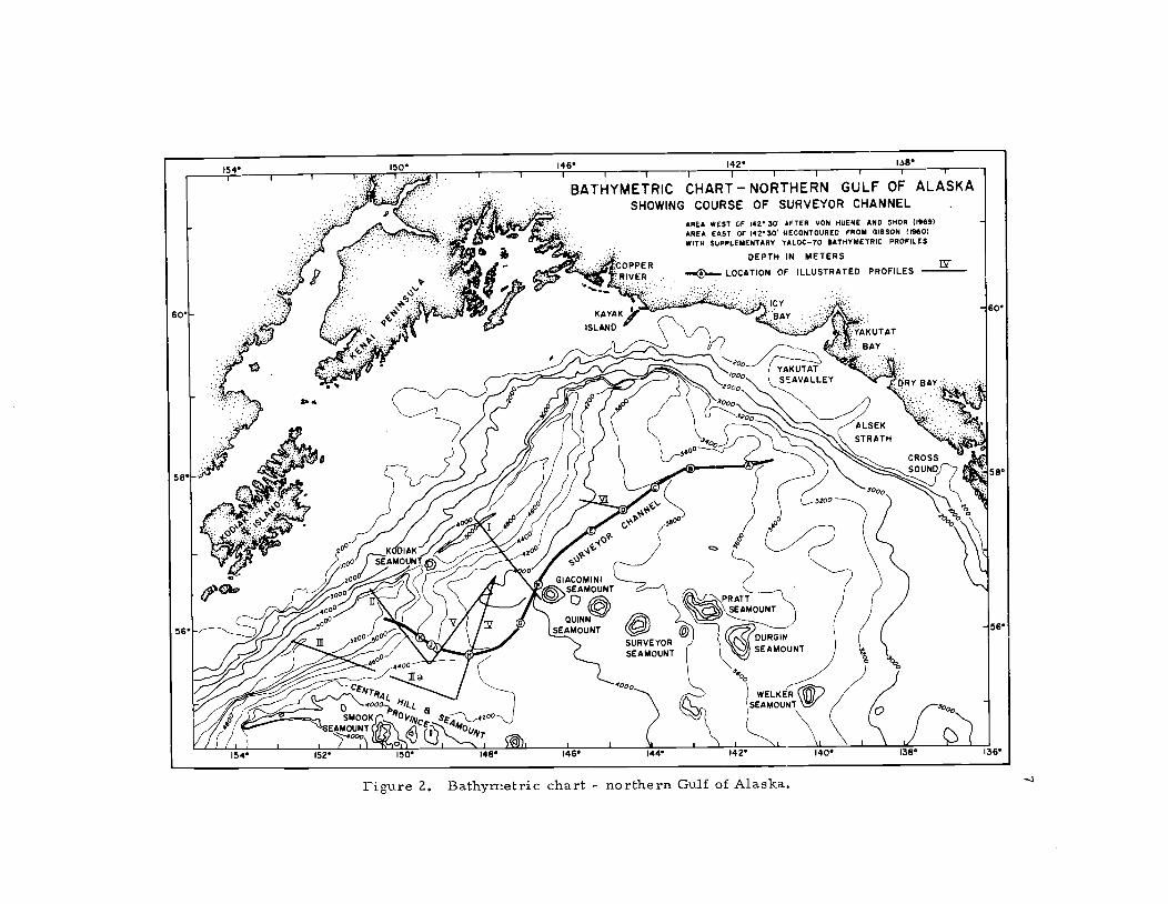
The course of Surveyor Deep-Sea Channel extends from the
northeastern edge of the Alaskan Abyssal Plain, near the base of the
continental slope adjacent to Yakutat Seavalley and Alsek Strath, to
the floor of the eastern Aleutian Trench immediately southeast of
Kodiak Island (Figure 2). Its length is approximately 700 km. The
general trend of the channel is parallel to the trench for over slightly
more than half its length, curving generally to the southwest. In the
vicinity of Giaconiini Seamount, the channel turns toward the north-
west and its gradient steepens as it plunges into the trench.
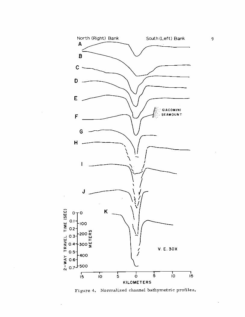
It is convenient to refer to three portions of the channel as
upper, middle and lower (Figures 3 and 4). In the upper portion
(profiles A and B), the relief in the center of the channel is in the
order of 100 m and the axial gradient is approximately 1.4 rn/km
(Appendix I). In the middle channel (profiles C, D, E, F), the relief
is fairly uniform at about 165 m, increasing slightly to 190 m near
profile F, and the axial gradient here decreases to an average of
about 1 rn/km. In the lower channel (profiles G, H, I, J, K), the
relief increases from about 200 in to more than 450 m. Similarly,
the axial gradient increases from about 2 rn/km to a value of 7. 5
rn/km at profile I, then decreases somewhat as the channel approach-
es the floor of the Aleutian Trench.
154 150 146 )42 I8I I I
II I I I I I I I I
BATHYMETRIC CHARTNORTHERN GULF OF ALASKASHOWING COURSE OF SURVEYOR CHANNEL
-
S. 0. AREA WEST OF 142 30 AFTER VON HUENE AND SHOR (1969),. . AREA EAST OF )42 30 NECONTOURED FROM GIBSON ((960)
WITH SUPPLEMENTARY .ALOC-7O BATHYMETRIC PROFILES
DEPTH (N METERS- LOPPER 1Y
-.j
IRIVER LOCATION OF ILLUSTRATED PROFILES
60 KAYAKICY
- ..
ISLANDBAY
. YAKUTATBAY
60
-:
'000 EAVALLEY bR YY BA:'
5858
& '
O0 2))
00 ii
f 0 KDIAK500 /iAMOUNT 00/
GIACOM IN)
AMUN)QWNN°
SEAMOUNT 56
154 152 150 I48 )46 144 142 140 138 136
Figure Z. Bathymetric chart - northern Gulf of Alaska.

DISTANCE ALONG AXIS (KM)700 600 500 400 300 200 tOO 0
I I I I I I I
C-)
m2
I-
mxz2P1I-
H
LOWER MIDDLECHANNEL CHANNEL
K
Figure 3. Channel axial gradient and center channel relief.Depths corrected from Matthews Tables (1939).
UPPERCHANNEL
3600
D
3800
40000
4200Irn
4400
rn3
4600U)
15000
0wU)
Lu
I-.
-JLu>
I-
>-4
c'J
North (Right) Bank South (Left) BankA
B
C
D
H
I
-T\\ rK\/
0.4 3O0/ V.E.30X
0.5400
0.6
0.7 500
15 JO 5 0 5 10 15
KILO MET ER S
Figure 4 Normalized channel bathymetric profiles.
10
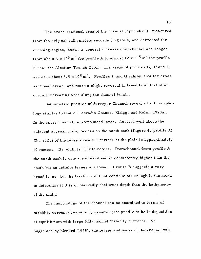
The cross sectional area of the channel (Appendix I), measured
from the original bathymetric records (Figure 4) and corrected for
crossing angles, shows a general increase downchannel and ranges
from about 3 x 10⁵m2 for profile A to almost 12 x 105m2 for profile
K near the Aleutian Trench floor. The areas of profiles C, D and E
are each about 5.5 x iOm2. Profiles F and G exhibit smaller cross
sectional areas, and mark a slight reversal in trend from that of an
overall increasing area along the channel length.
Bathymetric profiles of Surveyor Channel reveal a bank morpho-
logy similar to that of Cascadia Channel (Griggs and Kulm, l970a).
In the upper channel, a pronounced levee, elevated well above the
adjacent abyssal plain, occurs on the north bank (Figure 4, profile A).
The relief of the levee above the surface of the plain is approximately
40 meters. Its width is 13 kilometers. Downchannel from profile A
the north bank is concave upward and is consistently higher than the
south but no definite levees are found. Profile B suggests a very
broad levee, but the trackline did not continue far enough to the north
to determine if it is of markedly shallower depth than the bathymetry
of the plain.
The morphology of the channel can be examined in terms of
turbidity current dynamics by assuming its profile to be in deposition-
al equilibrium with large full-channel turbidity currents. As
suggested by ivlenard (1955), the levees and banks of the channel will
11
be here considered to have been constructed by periodic sheetfiow
spillover from large turbulent flows of suspended sediment moving
downchannel. Three approaches will be used to discuss the morpho-
logy of Surveyor Deep-Sea Channel as a function of turbidity current
dynamics.
Contrast in Bank Heights
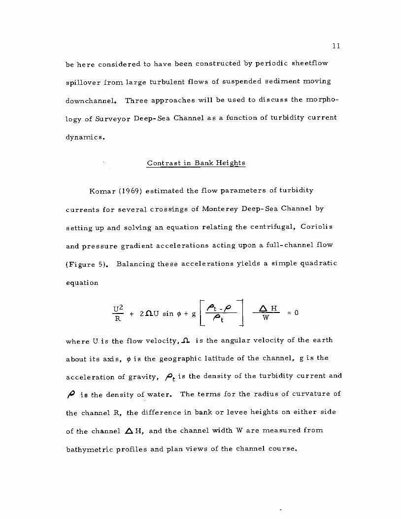
Komar (1969) estimated the flow parameters of turbidity
currents for several crossings of Monterey Deep-Sea Channel by
setting up and solving an equation relating the centrifugal, Coriolis
and pressure gradient accelerations acting upon a full-channel flow
(Figure 5). Balancing these accelerations yields a simple quadratic
equation
U2 AH-r
+ 2fltJsin+J
=0
where U is the flow velocity,.fl.. is the angular velocity of the earth
about its axis, is the geographic latitude of the channel, g is the
acceleration of gravity, / is the density of the turbidity current and
, is the density of water. The terms for the radius of curvature of
the channel R, the difference in bank or levee heights on either side
of the channel A H, and the channel width W are measured from
bathymetric profiles and plan views of the channel course.

;../'
/ 'T
R
Figure 5. Channel morphologic parameters
N)

13
If, in the northern hemisphere, the right bank of a channel is
higher than the left, looking downchannel, the Coriolis acceleration
must either add to the centrifugal acceleration (a left turning channel)
or be of greater magnitude but opposite sign (a right turning channel).
For the left bank to be higher than the right, the centrifugal accelera-
tion must exceed the Coriolis acceleration and be of opposite sign (a
right turning channel). With a straight channel course, the radius of
curvature goes to infinity and the centrifugal term drops out of the
equation. The right bank should therefore be higher than the left.
These relationships of the channel course to the bank heights
were found by Komar to hold for crossings of Monterey Deep-Sea
Channel. Using measurements of H, W and R, Komar calculated
curves of U versus from the above equation. The method has
also been applied to Cascadia Deep-Sea Channel using data from
Griggs (1969) and was found to yield reasonably consistent velocities
where the radius of curvature could be unambiguously determined
(Ness, 1970). The method of solving for velocities has not been
applied to Surveyor Deep-Sea Channel since the number of normal
oriented crossings is insufficient to accurately determine the
necessary morphologic parameters. The illustrated profile,s
(Figure 4) are however consistent with prediction, the right (north)
bank being always higher than the left, particularly in the linear and
steeper upper channel where the velocity dependent Coriolis term

14
dominates. The difference between bank heights decreases down-
channel from crossing H where the channel curves to the right and the
centrifugal acceleration opposes but does not exceed the Coriolis
acceleration. Profile K (Figure 4) is from a crossing at an angle to
the channel course on the steep seaward rise of the trench. Geo-
metrically adjusting the profile to be normal to the channel course
corrects for true horizontal distances, but the artificially high bank
height difference cannot be so removed. In any case, the right bank
is higher than the left and this is consistent with the other lower
channel profiles.
It is significant that the bank height morphology of the three
deep-sea channels so examined can be accounted for without exception
using the method of Komar. In no case does a measured channel
profile contradict its predicted morphology as would, for example, a
profile of a left turning channel in the northern hemisphere with a
higher left bank. The lack of contradictory evidence strongly implies
that the Coriolis, centifugal and pressure gradient accelerations are
dominant influences in the depositional formation of deep- sea channels.
It is further significant that the method applies equally well to
both the upper and lower, leveed and non-leveed, portions of deep-
sea channels. The non-leveed bank height contrasts commonly exhi-
bited in long bathymetric profiles from middle and lower portions of
both Cascadia (Griggs and Kulm, 1970a) and Surveyor Deep-Sea

15
Channels are therefore most probably related to deposition from the
differential spiflover of channelized turbidity currents.
Center Channel Relief
Komar (1972) analyzed the relative thickness of the head and
body of channelized turbidity currents and their relationship to the
channel axial gradient and the center channel relief. The equation
expressing this relationship isI
( hh= \h ) Fr
where V is the velocity of the head, Ti is the velocity of the body, hh
is the head thickness, hb the body thickness, and Fr is the Froude
number which is in part slope dependent. Komar found that for a
Froude number of 0.75 (corresponding to an axial slope of about 2.2
mlkm), the thickness of the head and the body of a flow should be
equal (Figure 6). For lower Froude numbers (lower slopes) the body
thickness will exceed the head thickness and channel spillover will be
predominantly from the body of the flow. For higher Froude numbers
(slopes steeper than 2.2 mfkm) the head thickness will exceed the
body thickness and spillover will consist of material from the head of
the flow. Suspended material within the head is continuously derived
from the body of the flow and the net velocity of the head is limited to
that of the body.

hb
hh
14
Sifl .48
0.0001 0.0010 0.0022
BODY SPILLING HEAD SPILLING
Ic.,JIcjiO
u,IoFtOdl"flI'
CLLu)
hh i I
FROUDE NUMBER, FrFigure 6. Relationship between center channel relief and
axial gradient.
1.5

17
For any given flow, the head thickness changes less in response
to changes in slope than does the body thickness. Therefore, even at
higher Froude number values, for reasonable slopes the head thick-
ness will not greatly exceed the body thickness. A typical channel of
constantly decreasing gradient should gradually increase in relief
over its length until, presumably at extremely low slope values
typical of central abyssal plains, the gravitational driving energy of
the turbidity currents becomes negligible and deposition occurs. The
break-up of the channel into a distributary network may also enhance
deposition of the suspended sediments.
The measured axial gradients of the upper and middle portions
of Surveyor Channel are all less than 2. 2 rn/km (Appendix I), with
profile A having the steepest gradient and therefore predictably the
least relief in the center of the channel. The middle channel gradients
are more gentle, and the measured relief correspondingly increases
in response to an increasing body thickness. Downchannel from
Giacomini Searnount, the axial gradients increase to values greater
than 2. 2 rn/km and the channel relief should therefore presumably
decrease in equilibrium with head spilling conditions. Instead, the
measured values of center channel relief continue to increase from
about 200 meters to more than 400 meters (Figure 3 and Appendix I)..
Surveyor Deep-Sea Channel is unique among known channels in that
its axial gradient increases markedly over the distal portion of its

length where it plunges into the Aleutian Trench. Over this length,
its relief greatly exceeds any values predicted upon an equilibrium
between the flow parameters and the channel morphology.
Cross Sectional Area
The volume transport of a full-channel turbidity current can be
estimated from the application of an equation of the form
Q=UA
where Q is the discharge rate, U is the average velocity of the
current and A is the cross sectional area of the channel. Since the
average velocity of the current is limited to the velocity of the body
of the flow, the motion of the current in a channel of slope is
governed by a Chezy-type equation of the formI12
L't gh (1 +) Cfj
where Cf is a bottom drag coefficient and ' is the ratio of the drag
at the upper interface of the current to the bottom drag (Komar,
1971). Assuming that no dilution of the flow by entrainment occurs,
and that the drag coefficients are constant, it follows that
IU °" (hb Sifl,
)2
and therefore that

19
Q S (hb sine)2 A
In effect, where the axial gradient decreases the velocity should
decrease, resulting in an increased channel cross sectional area for
a given discharge. Values of (h sin,)2 A for the Surveyor Deep-Sea
Channel bathymetric profiles have been summarized in Appendix II.
Assuming a constant discharge Q, a predicted area for any
profile A relative to the measured area of another, A, can be deter-
mined from the relationshipI
A1[hsin$ 12
h.sinp A1 iJ
Predicted area curves so generated (Figure 7) show that measured
middle channel areas are consistent with respect to one another. The
analysis predicts the smaller area of profile F and perhaps even G.
The slope used for crossing F is the downchannel slope, that is, the
change in axial depth between crossings F and G (Figure 3). It would
be equally valid to choose the upchannel depth contrast between
crossings E and F to determine the slope at F. Curves fit through
areas C, D and E would then fall only slightly below area F, and area
G would appear to be more in equilibrium with the middle channel.
The true slope at F is probably of some intermediate value, but the
distance between crossings is too great for a finer resolution.
The measured cross sectional areas of profile A and perhaps

DISTANCE ALONG AXIS (K M)
600 500 400 300 200 100 0I I
PREDICTEDAREA CURVES
I
H
T
I
A
-I- _D B0_____.rC0 -T-0 .i 0--
-I-
Figure 7. Measured channel cross sectional area from profiles Athrough K. Vertical bars include ± 15° ambiguity incrossing angles and errors in determining depths basedupon the scale of each original record.
C,I200
400
600
800
1000
1200
C)cIoU)
m-4(1)mmCj)1r3
I-
m
C

21
profile B are smaller than the predicted areas, area A being only
about half the predicted value. Since no channel crossings were made
east of crossing A, its actual slope is unknown, and it may be much
steeper than the downchannel value chosen which might explain its
small area. An alternative explanation for this will be discussed
later.
Most important to this discussion however, is the fact that
measured lower channel cross sectional areas are dramatically out
of equilibrium with middle channel areas, being larger by as much as
a factor of three (and even more with respect to their own predicted
values).
In summary, the depositional aspects of the morphology of
Surveyor Deep-Sea Channel show expected characteristics. Leveed
banks occur in the steeper upper reaches of the channel. The
occurrence is similar to that of Cascadia Deep-Sea Channel (Griggs,
1969) and appears to be common for channels developed on steeper
slopes and on the upper reaches of deep-sea fans (Normark, 1970).
The non-leveed banks of the middle and lower channel exhibit a bank
height contrast in conformity with their depositiona]. development
from the spillover of channelized turbidity currents. The lower
channel however is distinctly dissimilar from the middle and upper
reaches of the channel with respect to both its increased cross
sectional area and its greater center channel relief. From the

22
vicinity of Giacornini Seamount to the Aleutian Trench, Surveyor
Deep-Sea Channel is not in equilibrium with its predicted model.
Seismic reflection records, which will be discussed next, strongly
suggest that the lower channel has undergone post-formational
ero sion.

23
SUB- BOTTOM STRUCTURE
Seismic reflection records taken over the northern Gulf of
Alaska reveal the ubiquitous nature of a characteristic series of sub-
bottom reflectors. They appear to be best developed near and to the
north of Surveyor Deep-Sea Channel, though some can be recognized
as far as 500 km to the south. Profile VI (Figure 8) from Yaloc 70
data, is the best detailed record in this study and most clearly
illustrates the nature of these reflectors. In general, four thick
stratified units can be recognized above acoustic basement.
Character of the Seismic Reflectors
The uppermost unit (Unit A) extends from the sediment-water
interface to a depth of 0. 2 seconds (two-way travel time). It consists
of a strong and continuous initial set of low frequency reflectors ex-
tending to a depth of about 0. 07 seconds. Between 0. 07 and 0. 2
seconds, except for a single strong reflector of 0. 14 seconds, weak
and higher frequency returns become increasingly discontinuous with
distance from the channel.
At a depth of 0. 2 seconds, a pair of strong low frequency re-
flectors, common to most of the records and only occasionally dis-
continuous, marks the upper interface of the second seismic unit
(Unit B). Below that, to a depth of 0.4 seconds, weak reflectors


show the same trend in discontinuity as those of the first seismic
unit.
25
At a depth of 0. 4 seconds a single particularly strong low fre-
quency reflector occurs within a group of several strong closely
spaced reflectors. These mark the top of the third seismic unit
(Unit C) which is about 0. 25 seconds thick. Other reflectors in this
unit are much less continuous and return higher frequencies than any
others in the section. Occasional strong returns of short horizontal
extent occur.
At a depth of 0. 6 to 0. 7 seconds, the final seismic unit (Unit D)
begins and extends downward to acoustic basement. It is character-
ized by strong, fairly continuous and somewhat deformed low fre-
quency reflectors throughout. Acoustic basement, poorly expressed
in Profile VI, is generally found at an average sub-bottom depth of
0.8 to 1. 2 seconds here and to the west of the section. A fifth
seismic unit occasionally appears ponded into basement lows below
0.8 seconds (Figure 9, Profiles I and II).
The reflectors at depths of 0. 2, 0. 4 and 0. 7 seconds in Profile
VI (Figure 8) are the most prominent throughout the region. The 0. 4
second set of reflectors, marking the boundary between seismic
units B and C, is found to have a particular importance in that it
most frequently seems to occur at or near the thaiweg (the lowest
point in a channel profile) of Surveyor Deep-Sea Channel. Its

27
determined age has a significant bearing on the origin and develop-
ment of the channel.
Age of the Channel Basal Reflectors
Seismic Profile I (Figure 9), kindly supplied by John Wageman
and Fred Naugler of NOAA, extends from the base of the landward
wall of the Eastern Aleutian Trench, southward across Surveyor
Deep-Sea Channel and terminates at the foot of Giacomini Seamount.
The profile passes closely by Sites 178 and 180 of Leg XVIII of the
Deep Sea Drilling Project (von Hueneetal., 1971). The prominent
set of reflectors at the base of the channel can be easily traced be-
neath D. S.D. P. Site 178 and into the trench. Near the drill hole, the
channel basal reflectors are found at a depth of 0. 34 seconds. The
seismic velocity of North Pacific Abyssal Plain silty turbidites, as
measured in the laboratory, is 1.634 km/sec (Hamilton, 1969).
Assuming this velocity, the channel basal reflectors lie at a depth of
275 meters. Cores recovered from the drill hole at Site 178 extend
to a basalt basement. To a measured depth of 270 meters, they
consist of middle Pliocene to Holocene gray-mud turbidites with
abundant ice-rafted debris (von Hueneetal., 1971). Below the gray
mud, the sediments recovered consist of interbedded silt and sand
turbidites, diatornaceous sediments and mud. The lithologic change
at a depth of about 270 meters is therefore seen to closely correspond

to the change in the character of the seismic reflectors at that depth.
The prominent reflectors at the base of the channel near Giacomini
Seamount may therefore be dated as middle Pliocene.
The basal reflectors can be traced on other records south and
east of Surveyor Channel into the central Alaskan Abyssal Plain.
They appear to continuously shoal in this direction. At a position of
530 01' N, 1410 41' W, a similar set of reflectors are found at a
depth of 0. 14 seconds. Assuming a seismic velocity of 1. 634 km/sec,
this corresponds to a depth of 115 meters. This location was chosen
for piston coring in an effort to obtain a long stratigraphic core for
the Alaskan Abyssal Plain in an area of presumed slow sedimentation.
A 17. 5 meter hemipelagic core was recovered. It was found to con-
sist of a medium gray silty clay with periodic thin silt laminae, each
about one or two millimeters thick. Several foraminiferal rich
layers and occasional ice- rafted pebbles are additionally found in the
core.
Oriented sections of the core were sampled for magnetic
stratigraphy at one meter intervals. The total field magnetic inclina-
tions of the undisiccated samples were measured on a 5 CPS spinner
magnetometer. To a depth of 16.5 meters, the total field magnetic
inclinations were found to be of normal polarity, with inclinations
from the horizontal of an average 65 degrees (Figure lOa). At 17. 5
meters, near the very bottom of the core, a reverse field sample of

90
60
30LU
wa 0
LU
c± --30
60
9090
60
U) 30UiUic 0CDLU
60
90120
,', 100EC) 80
22000
CORE Y70-456 5301O'N141041'W
a) ORIGINAL INCLINATION
c) INTENSITY0 \
\ ORIGIN A L
\' . / \--. /\_- - 75 oe
2 4 6 8 tO 12 14 16
DEPTH IN CORE (METERS)Figure 10. Magnetic stratigraphy of Core Y70-4--56
29
18

30
-30 degrees was measured. The meter interval between the last
normal sample and the reversed field sample was then more closely
examined. Three additional reverse field samples were found, the
highest occurring at a depth in the core of 16. 9 meters. Several
samples were then A. C. demagnetized at successively increasing 25
oersted intervals using a 3-axis demagnetizer. At each level, their
remnant magnetic field orientation and intensity were measured. It
was determined that a 75 oersted A. C. field was sufficient to
remove secondary magnetic components. All samples were then de-
magnetized at this level. The specific intensity of most of the demag-
netized samples decreased to about half their original values
(Figure lOc).
Measured normal polarity inclinations of the demagnetized
samples (Figure lOb) decreased to an average of 40 degrees, with
only a small scatter about that value. This inclination corresponds
to a geographic latitude of only 23 ° N. The original normal polaiity
inclinations averaged slightly more than 65 degrees which corres-
ponds to a geographic latitude of 47 ° N. While the original inclina-
tions are reasonably close to values predicted from the geographic
latitude of the core location, the demagnetized inclinations greatly
deviate from predicted values. No explanation for this abnormal
result is here offered.
Both original and demagnetized inclinations indicate that a

31
paleornagnetic field reversal occurs in the core at a depth of 16.7 ±
0.2 meters. Assuming this to be the Brunhes-Matuyama Epoch
Boundary, the age of the core at this depth is 6.9 x 10 years B. P.
(Cox and Dairymple, 1967). The average sedimentation rate for the
core since that time is therefore 24. 3 ± 0. 3 meters/rn. y. Extrapo-
lating this sedimentation rate to the basal reflectors, found at a depth
of 115 meters at the core site, yields an age for that surface of
4. 75 .± 0. 06 rn. y. B. P. Using the most recent time scale of
Berggren (1972) this date is found to be within the early Pliocene.
This is reasonably consistent with the middle Pliocene age found for
the 270 meter reflectors at D. S. D. P. Site 178 (von Huene et al
1971).
The basal reflectors are therefore seen to be roughly time syn-
chronous over the 500 kilometer distance between the central Alaskan
Abyssal Plain stratigraphy core and D. S.D. P. Site 178 (Figure 2).
Calculating a sedimentation rate, using a 1. 634 km/sec seismic
velocity, for the units above the basal reflectors at Site 178 yields a
value of 56 meters/rn, y. or slightly more than twice the rate on the
central abyssal plain 500 kilometers to the southeast and distant from
Surveyor Deep-Sea Channel,
Longitudinal Development of the Channel
Figures 11, 12 and 13 are equal weight line drawings traced

T1
I-..
CD
I- I-
2-W
AY
TR
AV
EL
TIM
E'1
ON
E S
EC
ON
DC)
.C
DI
"II
WC
D
ii,
1
I 0
I
',biili 1ij
hr
CD
Iii
,i
) jji.
I
"'
Ii
i'"i
0
Ii/I
li
/i
1l I(
'i"
I/!
1(i?/
11w:L
Iii
I I
4
1iSIIi
I1":
I
1\t.1'''
i; '
i;
" I
Ii'
;h
hi!
I '!,,,,II1i:;i,
VA 0
Ii'Ihhhj;iI,"
CH
AN
GE
-__
____
____
__I
CO
UR
SE
i'ii p
g >
øil
ro
".
L"
rr u
I0
I
1k1
Il.I.I
C -l-
flIQ
i'"'
I
ipili
III ig

Irj
I-."
CD
CD
C) CD
CD
CD I
$.
III
fl$
sill
ill 11
Iii'
'I
iII
tt
I
''.ljt
ii ii'i
iL
llJi
IIi
II
Ill
III
III,
'I
II
ii
i
"I
I \'"
SI
I.
I
ONE SECOND
2WAY TRAVEL TIME
ti I
\
'I
"
'I'
'I'
''I
. \\\
I'
I
\ 't
I.
'I
\\\''
%\I
''I '1"
m
0 r)
z 0 :3-
sale
II IS
II
ill'
'I
'
'clt'
"
I
I
'id
i1liL:7i
'I//i
)jl I
:,
1
I,
1;
U) 0 :
3-
C)
1*
111
VIII
SI
I' I
Is$
[0
11111
IliIt
I*
IT
I0
Lrs) 0
1int
L0
I)IJI
'' I'
fiJi
IId
hfiI1
iIII
j
(Ii It
Ih
1)I1
Illilliw L1
ii
11(11)
IlI(IIJ I!I jIl
I
jjJ
ii
I
i/,
I
jjJ1//JJJJ
I
'I
/I
III
iIj
iIt
I!)
((il
(I
IiiIiiI(iii"
'1
tti
I
a'
IItI
ILt'
ii'i
\\
,1iII\ tttII1
I
:4"
1i)i 4i
'iii
'ij
1) 11II
Ii
0
I
Iill
CD
Ili))
i)
j)((Ii)!,)
,y/&J//v%
,CD
CD
''
't
--
"\''S_)
1-
-\tt
'% '
1)1111
i)
;I'
11111//sI
Ill
I)///)I
I
CD) '
1)IIJ
/'
I'll)',' !/(///////'J1
i//
Ill
''Jill
,I
i'
:j
,.
Ill! In
Ii
'ill
I
Ill
111111i1iiiiLH
')2
"I
II
I1111
,llII'I'll
IIIII/Ii(ii
ill)
I
/JI
ill
Ii/ Ill!. huh
11111
I)
'
Ii
'II'111Ii
I
"if
Iii
ii' It jjJj I,
'I
Is
I
I 4Jj
,i((j,i 11111
11
/iiil1ciiii
ifr'i1
lit
I ill
2WAY TRAVEL TIME
ONE SECOND
FI
I
z iIii1I11 iii
i
I
,ii
litillill
''JI1I
''
I'thitl(
l(
jiil
IIJ
1
IIIIJIJ 'II
I
ii
/
I(i ''I iJii,'ti
111111
I!''!
11IlIlIii
II!
J(ilI
Ii liii
I Ii
liii
'ii
iIII''
II 'II
I
'1,11,1
1
'
II
I
'i's
Iil illilt Ill
hi
11111
I
IItlIl
'ii'
I]
Ii
II'
'III
II
I
ill
it
'
Ill,)
,,,
,,/,':,3'
/
,ilI/ul
'((lit
J1tII
''\t\\_
It
t
1
i11t
till
tI
t1tl
liii
II
II)I I'htIII I IJI)
ii 1iIttl
JIi
Ii
IIIIltiI
I 'iii
1111
II
I
IIIIIILtIIII''i'
II uiji
ill,
lii
11111(1
hII
'111111
I(Ii
(lit
tI 'IlIilItIIwlt,IIll
Ii1l 1
1111.111
lilt
iiigi i IiI!iIiIIi
(Iii ii
Ill
1'i I I II'"
11111
(.J)
''
I
I ll! I('Il II
IiIIJ
Is'
lull 1,11 III I
C i'
iIIiIilIII IIlI
I ll'liJiI
'flit
rf_
iiIll III' 111111
I
'
(71

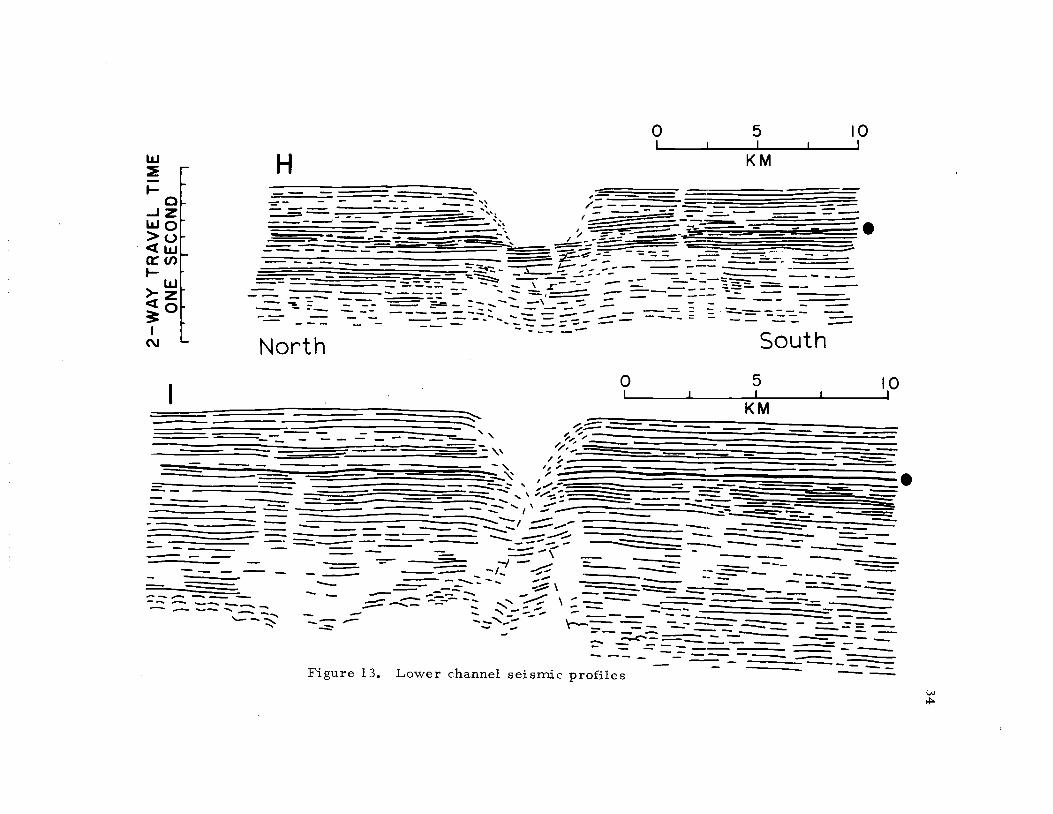
35
from the original seismic records of eight channel crossings and re-
duced to the same vertical scale. The indicated horizontal scales are
not normalized with respect to the course of the channel. The channel
basal reflectors are drawn in a bolder line and are further indicated
by filled circles beside each profile. These reflectors were not re-
cognized in profile A and presumably lie below the penetration depth
of the seismic record. The sediment thickness above the basal re-
flectors is seen to increase upchannel toward the east. It is about
0.3 seconds (245 meters for a seismic velocity of 1.634 km/sec) at
profiles H and I, and about 0. S seconds (410 meters) at profile B.
The position of the thaiweg with respect to the basal reflectors also
shows a consistent variation upchannel. It is at the same depth at
profile F, and 0. 22 seconds (180 meters) above the surface at
profile B.
Upper channel profiles A and B, found to be morphologically
distinct from the rest of Surveyor Channel as previously discussed,
exhibit sub-bottom characteristics that further distinguish them
(Figure 11). Their broad, smoothly rounded banks and gentle channel
wall slopes are mirrored by reflectors that show a tendency to con-
formably dip downward toward the channel axis. The bank reflectors
approximate the idealized depositional channel profiles of Hamilton
(1967) and Normark (1970). The many small angular discordances,
particularly below the thaiweg near the Pliocene surface in profile B,
IT1
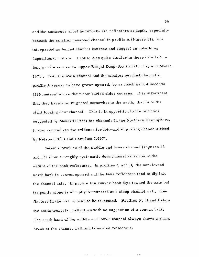
and the numerous short hummock-like reflectors at depth, especially
beneath the smaller unnamed channel in profile A (Figure 11), are
interpreted as buried channel courses and suggest an upbuilding
depositional history. Profile A is quite similar in these details to a
long profile across the upper Bengal Deep-Sea Fan (Curray and Moore,
1971). Both the main channel and the smaller perched channel in
profile A appear to have grown upward, by as much as 0. 4 seconds
(325 meters) above their now buried older courses. It is significant
that they have also migrated somewhat to the north, that is to the
right looking downchannel. This is in opposition to the left hook
suggested by Menard (1955) for channels in the Northern Hemisphere.
It also contradicts the evidence for leftward migrating channels cited
by Nelson (1968) and Hamilton (1967).
Seismic profiles of the middle and lower channel (Figures 12
and 13) show a roughly systematic downchannel variation in the
nature of the bank reflectors. In profiles C and D, the non-leveed
north bank is convex upward and the bank reflectors tend to dip into
the channel axis. In profile E a convex bank dips toward the axis but
its gentle slope is abruptly terminated at a steep channel wall. Re-
flectors in the wall appear to be truncated. Profiles F, H and I show
the same truncated reflectors with no suggestion of a convex bank.
The south bank of the middle and lower channel always shows a sharp
break at the channel wall and truncated reflectors.
37
Some of the apparent truncation is without doubt due to hype r-
bolic side returns. Normark (1970) illustrated the contrast between
bathymetric profiles taken by a ship at the surface and those taken
near the bottom by a deep-towed sounder. The difference is striking.
Changes in bottom relief are obscured and even completely masked
by hyperbolic returns on surface profiles. The effect would be
mitigated in low frequency seismic profiling by the use of hydrophone
streamers whose front to back beam widths are quite small. One can
still however expect an artificial hyperbolic lengthening of internal
bank reflectors to some unknown extent into the channel. The effect
would be more pronounced in deep water and on steep channel walls.
It would also tend to decrease the channel cross sectional areas for
deeper profiles, particularly wide-beam bathymetric profiles.
The presence of flat and truncated reflectors is often used as a
criterion for establishing the erosional nature of deep- sea channels
(Normark, 1970). It is suggested that a certain caution should be
used when applying this criterion. Fine scale seismic profiling, as
from a deep-towed vehicle, may reveal that the apparently flat and
truncated reflectors may in fact have fine scale depositional charac-
teristics near the channel wall that are masked by hyperbolic effects.
Furthermore, the transverse velocity profile of a channelized tur-
bidity current is without doubt not constant over the whole flow-
sediment interface. It is therefore easy to envision different

phenomena occurring over the channelized width of a turbidity
current, particularly when one realizes that typical channel profiles
are one to two orders of magnitude wider than they are deep. Thus,
deposition may occur at the bank crest synchronous with transport in
mid-channel. Similarly, transport may be taking place along the bank
wall while erosion is occurring in mid-channel and spillover deposi-
tion taking place on the bank. And, since the size, frequency and in-
tensity of these periodic flows is apt to be quite variable, different
flow events are quite likely to cause some variation in the kind of
process that takes place at any given point in the channel. Channel
profiles most probably reflect some sort of average effect of the
larger flows. With these qualifications in mind then, it is perhaps
valid to characterize portions of a channel as depositional, transpor-
tational or erosional. Several other criteria need to be applied.
Seismic crossings of lower Surveyor Deep-Sea Channel
(Figure 13) show hyperbolic returns from the channel walls ei±ending
to depth in the sediment beneath the channel thalweg. It has been
pointed out that measured cross-sectional areas of lower channel pro-
files are much larger than predicted values. The presence of
hyperbolae suggest that the cross-sectional areas may in reality be
even larger for these deeper crossings. The channel thaiweg itself
is found to be deeper than the Pliocene channel basal reflectors, and
the axial gradient here is steeper than the middle and upper channel
39
gradients. For all of these reasons, the lower channel as a whole is
here considered to be erosional. The obvious fill in the bottom of
channel crossing H is evidence of the variability that can and does
occur in channel related turbidity current processes. For the criteria
previously cited (upbuilding above the basal reflectors, the presence
of levees, axially dipping bank reflectors, evidence for migration and
cut and fill, low channel relief, and small cross- sectional area) the
upper channel is here considered to be dominated by depositional
processes. And for similarly consistent criteria, the regimen of the
middle channel is considered to be largely transportational.
CHANNEL RELATED SEDIMENTS
Long seismic profiles of the northern Alaskan Abyssal Plain
show that the seismic units previously described extend with fairly
uniform thickness throughout the region. Profiles I through III
(Figure 9) reveal that the entire sequence of seismic units, including
the channel related uppermost Units A and B (Figure 8) are buried be-
neath trench fill to the north. The interface between seismic Units B
and C, that is between the channel related and the prechannel sedi-
ments, is nowhere seento possess characteristics indicative of any
older buried channels. The sedimentary section described at
D. S. D. P. Site 178 indicates that the sediments making up Units C and
D are nonetheless turbidites (von Huene et al. , 1971) and therefore
are probably related to either a pre- exi sting channel system,
similar in orientation to Surveyor but not now found, or are derived
from a northern pre-trench source. The channel related sedirrnts,
comprising seismic Units A and B, recovered at D. S. D. P. Site 178
are finer grained silt turbidites in a glacial gray mud.
Thirteen piston cores were recovered from the Gulf of Alaska
during the 1970 cruise of the Oregon State University Research
Vessel Yaquina. They include three cores from the axis of Surveyor
Deep-Sea Channel, three from the channel banks, six from the
Alaskan Abyssal Plain and one from the easternmost Aleutian Trench

41
axis (Figure 1). For the purposes of this effort, the cores have only
been examined for gross textural features.
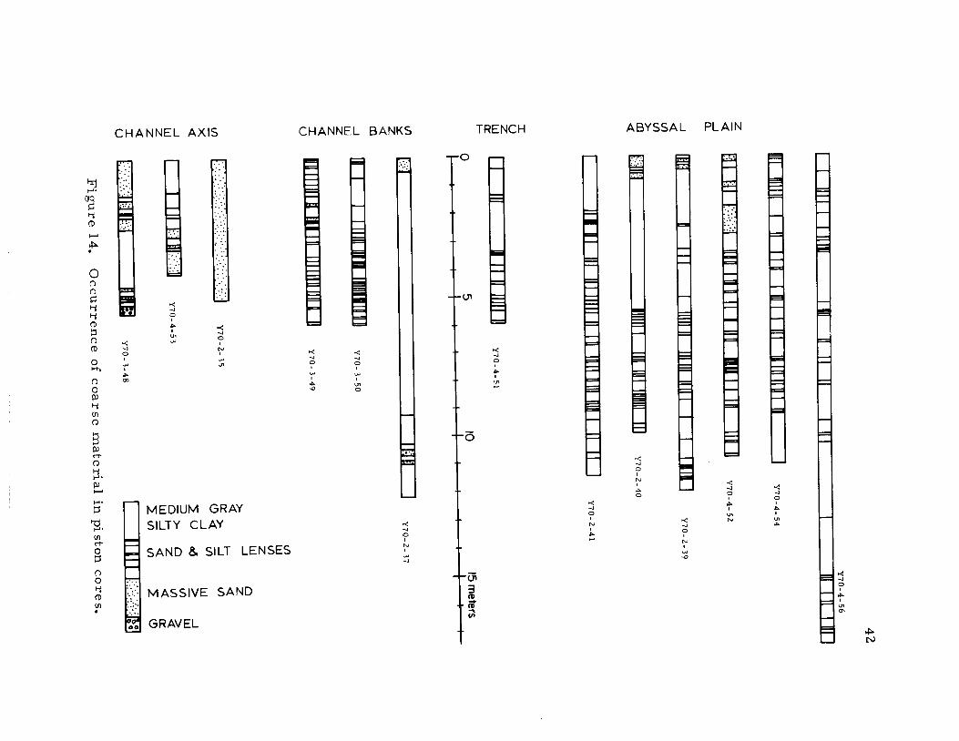
Without exception, all thirteen cores exhibit characteristics
that allow them to be classified as turbidites. A very few contain
graded sand and silt members, and the medium gray silty clay
making up the bulk of the cored material is occasionally finely laminated
(Appendix IV). Relatively thick sand members are found in the axis cores,
and occur near the top of three of the abyssal plain cores. All of the
abyssal plain and bank cores except one contain frequent fine lenses
of silt or sand (Figure 14). They also contain abundant ice- rafted
pebbles. Similarly, the occurrence of sand grains homogenously
distributed throughout silty clay members suggests transport by ice-
rafting. The overall lithology is seen to be quite similar to that
describing the upper 270 meters of sediment recovered from D. S. D. P.
Site 178 (von Huene etal., 1971), and suggests that glacial and tur-
bidity current activity have been continuous throughout the region
from Pliocene time to the present.
The textural contrasts within and between the channel axis
cores indicate a high degree of unpredictability in the downchannel
energy variation of channelized turbidity currents. The presence of
thick sand members near the tops of two of the axis cores, including
the most distal Core Y70-2-35 suggests that turbidity current
activity is presently operational in the channel Itself.
42
iiiiiU
11iR
uIuiII
tiiIIuuiIuituiiiiiiiiitiiiit<
F III
11111111111 lIDff11 11111
IiiII
-j0.-J
I11IiII
II
I1
11(11II
III 11111111
1I
III
Y70- Z- 39
4(1
If)
mIJ1L1
111111I
1111III I
11111111II]
Y70-2-40
4
111111III
III 11111 111111111 01111110
III
II1
Y70-2-41
I0zLiJ
I.fl
z4w-J
LUzz4IU'I)
x4-JUizz4IU
II
IllI liii 11111
11
05
tO
15 meters
II
I
iiUuiinuii
I 11111111 IIIIlII'1rLI1,:
I JiflJI UI iU
IIUIIIIlIU
IIIIUI'a'.iu
II
Y70 Z 35
IJflH
1
(I)
LUIf)
z
>-4
LU-J
zI--J
4u)If)
LU-J
2If)
ILl
w<
4:lMIf,
IIIIIY70-3-48
11111 l:::.':::Th1
Figure 14.O
ccurrence of coarse material in piston cores.

43
The spatial distribution of the three bank cores does not allow
discussion of any systematic downchannel textural variation in the
bank sediments. It is interesting however that Core Y70-2-37 con-
tains almost 850 cm of only faintly laminated silty clay. No silt or
sand lenses occur throughout that length of the core. The core was
recovered from the north bank of the lower channel. The high relief
of the lower channel may preclude coarse grained recent spillover
from all but the largest flows.
Several abyssal plain cores contain near surface sand members, again
suggesting that turbidity current activity is presently operational
even over the abyssal plain. There is the suggestion in the distribu-
tion of coarse grained materials that sand members may be more
common in areas near the channel or the continental slope than in
central plain regions. There also seems to be a similar variation in
the frequency of occurrence of coarse lenses in general. Alterna-
tively, this variation may represent a tendency toward the thickening
of individual turbidite sequences with distance from the channel or
slope. A similar trend was found to occur in Cascadia Channel
(Griggs and Kulm, 1970b).
The presence of thin sand and silt lenses even in the most
central portions of the Alaskan Abyssal Plain strongly implies that
spillover from turbidity currents is not confined to regions close to
the channel, Similarly, the ubiquitous nature of seismic Units A and
B suggest that channel related turbidites make up the entire abyssal
plain. Griggs (1969) was able to trace the sediment from less
vigorous Holocene flows to a lateral distance of 17 km away from
Cascadia Channel. Presumably, more vigorous glacial turbidites may
be capable of more intense spilling. The uniform thickness and
character of seismic Units A and B and the presence of turbidites
throughout the abyssal plain can be most reasonably explained in
terms of very broad, sheet flowing, and fine grained currents contin-
uously spilling from the channel and traveling over large expanses of
the abyssal plain. The higher velocity, more turbulent and coarser
grained portion of any flow would be confined to the channel. It is
important to stress that the channel and its related sediments, corn-
prising seismic Units A and B, seem to be related to the initiation of
glaciation onshore. Similarly, Site 183 of D. S. D. P. Leg XIX on the
Aleutian Abyssal Plain to the west, yielded cores that contain glacial
erratics to an approximate depth of 130 meters near the base of the
Pliocene (Scholletal., 1971). Site 178 of D.S.D.P. Leg XVIII
yielded a similar age for the initiation of glacial activity.

45
CHANNEL RESPONSES TO REGIONAL TECTONISM
In two aspects Surveyor Deep-Sea Channel shows a pronounced
response to regional tectonic influences, the scale of which makes it
unique among deep- sea channels. In addition to those morphological
and structural characteristics already discussed, there is evidence
that strongly suggests that the upper channel was formed near the base
of the continental slope by the coalescing of broad, sheet flowing,
turbidity currents. This unusual origin is suggested by the location
of the channel relative to regional bathymetric and tectonic features.
The erosional nature of the lower channel is seen to be consistent
with the regional late Cenozoic history of lithospheric plate inter-
actions.
The Eastern Source of Sediments
Bathymetric maps of the northern Gulf of Alaska (Menard and
Dietz, 1951; Gibson, 1960; Hurley, 1960) indicate that Surveyor Deep-
Sea Channel is not contiguous with any prominent submarine canyon.
This is unusual in that other known deep-sea and fan channels appear
to be proximally associated with canyons. Examples include
Cascadia Channel and Willapa Canyon (Griggs, 1969), Astoria Fan
Channel and Astoria Submarine Canyon (Nelson, 1968; Carlson,. 1968)
and Monterey Canyon and Monterey Deep-Sea Fan Channel (Martin and

Emery, 1967; Wilde, 1965). Chase, Menard and Mammerickx, on
their chart of the bathymetry of the North Pacific (1969), show a
prominent submarine canyon on the continental slope west of Alsek
Strath contiguous with Surveyor Deep-Sea Channel. Bathymetric and
sub-bottom seismic records from a single crossing of this area by
the R/V Yaquina (Figure 1) fail to show the feature. Negative evidence
from a single crossing in an area of high relief hardly rules out the
possible existence of such a canyon, but it is also significant that no
canyon appears to the north opposite Yakutat Seavalley. The smaller
channel shown in seismic profile A (Figure 11) is assumed to trend in
this direction. This conclusion is supported both by the location of
the channel and by the fact that its south levee is slightly higher than
its north levee. The levee relationship can be explained if the channel
course here is turning sharply to its right, allowing the centrifugal
accelerations on turbidity currents to equal or slightly exceed the
Coriolis accelerations. This argument aside the bathymetry of the
upper channel region is also unusual.
Large lobate bathymetric highs on either side of the channel
near the lower continental slope seem to confine the channel to the
broad bowl-shaped depression indicated by the 3400 and 3600 meter
bathymetric contours shown in Figure 2. Sub-bottom seismic
profiles across the lobes do not penetrate to a recognizable acoustic
basement. In fact, a definite basement is not resolved on any of the

47
seismic profiles east of Giacomini Seamount. It is therefore not
possible to determine whether the lobes have any deep structural
control. In any event, it is unusual that the upper channel is confined
to a broad bowl-shaped depression instead of being situated on a
bathymetric high or a conate fan.
The main trace of the Chugach-Fairweather Fault was shown by
Stoneley (1967) to lie just east of the coast line behind Yakutat and
Dry Bays (Figure 1). In this region it is only about 70 km inshore
east of Yakutat Bay, 30 km inshore near Dry Bay, and exits the coast
at Cross Sound at about 137° west latitude (Figure 1). Stoneley pro-
posed two periods of intense folding and thrust faulting in the Gulf of
Alaska sedimentary province, one in the late Cretaceous - early
Tertiary and another in the Plio-Pleistocene. He also found evidence
for dextral strike- slip motions along the Chugach-Fairweather Fault
system. St. Amand (1957) mapped the Queen Charlotte Island Fault
system on the Chichagof, Baranof and Queen Charlotte Islands.
McKenzie and Parker (1967), Morgan (1968) Le Pichon (1968), Isacks,
Oliver and Sykes (1968) and others have treated the Fairweather-
Queen Charlotte Island Fault system as a large ridge-trench trans-
form fault extending from the Explorer Ridge, seaward of northern
Vancouver Island, to the subduction zone landward of the Eastern
Aleutian Trench. The dextral fault system constitutes a boundary
between the North American and Pacific Plates.

Morgan (1968) has estimated the present angular rate of motion
between the North American and Pacific Plates to the 6 x 10
degrees/year about a rotation pole at 530 N., 530 W. At the rotational
equator, this corresponds to a 6. 7 cm/yr velocity for motion of the
Pacific Plate relative to North America, The latitude of the trans-
form fault system relative to the pole of rotation is about 450,
therefore the relative rate of dextral offset across the system should
be about 4.4 cm/yr. Heirtzler and others (1968) show that this sense
of plate motion has been in effect at least since anomaly 5 time about
10 m. y. B. P. The implication for Surveyor Deep-Sea Channel -is that,
since its origin at no more than 5 m. y. B. P., it has moved approxi-
mately 220 km to the north with respect to its initial sediment source
on the adjacent continent. At the time of its Pliocene origin the
upper channel would have been located southwest of Cross Sound.
Therefore, unlike other major deep-sea channels, Surveyor has not
been consistently linked to any large river drainage system that
might serve as a sediment source.
The Pacific Plate in moving north has been carrying with it the
thin slice of continental crust west of the Chugach-Fairweather-
Queen Charlotte Island Fault system. South of Icy Bay, this slice is
composed almost totally of the Mesozoic Eugeosynclinal facies of the
Yakutat group (Støneley, 1967). North of Icy Bay, the Plio-
Pleistocene Yakataga Formation consists of a lower marine mudstone

49
- siltstone - silty sandstone member and an upper conglomeratic
silty mudstone member containing glacially striated boulders up to
35 meters in diameter. Coupled with a high variability in the
measured thickness of units, the conglomeratic facies lead Stoneley
to conclude that the region began undergoing intense deformation and
glaciation by early Pliocene times.
Glacial activity in the region is substantial at present and must
have been even more intense during Plio- Pleistocene cold cycles.
Major glaciers exist throughout the region forming an almost con-
tinuous ice sheet in the mountainous terrain east of the Gulf of
Alaska. Several large piedmont glaciers extend to the present shore-
line, During the late Pleistocene, the area was completely covered
with ice (Coulter et al,, 1962), The Malaspina Glacier between
Yakutat Bay and Icy Bay is presently more than 70 km wide and 3. 5
km thick at its center, and is in rapid retreat. The neighboring
Guyot Glacier has retreated 40 km up the fjord at Icy Bay in 60 years.
Wave-cut platforms are elevated more than 1, 5 kilometers above sea
level and Stoneley suggests that the deep glacial-cut fjords were cut
below sea level during colder cycles. The broad depressions of
Yakutat Seavalley and Alsek Strath extend from Yakutat Bay and Dry
Bay across the continental shelf, Similar structures are found west
of Icy Bay (von Huneetal,, 1971), These features show both a
genetic structural control, being situated along synclinal fold axis,

1i
and a glacial modification by erosion and subsequent filling. They
constitute evidence that the glacier system extended across the entire
shelf during cold cycles.
In addition to the foregoing, the region is characterized by high
seismic activity. The area from Icy Bay to Cross Sound has experi-.
enced at least four earthquakes of greater than 7.0 magnitude in
historic time (Davis and Echols, 1962), and is marked by a high
strain release (Berg, 1964).
A consistent and unique picture emerges. In the early Pliocene
intense folding, faulting and uplift along the continental margin of the
northeastern Gulf of Alaska, coeval with the initiation of glaciation,
provided large volumes of poorly sorted coarse clastic material
along a broad front on the outer continental shelf and upper slope.
Intense earthquake activity would periodically initiate wide, massive
slumps in this material that would then move down the continental
slope and entrain large volumes of water in transit, Upon reaching
the base of the slope, this sheet flowing mass would begin to deposit
some of its suspended load and move onto the abyssal plain. Here it
would be constrained and funneled inward by pre- existing bathymetric
highs, which may represent oceanic crustal analogs of the folded
structures found on the immediately adjacent continental shelf. The
funneling would result in the development of high velocity jets within
the flow. Fan channels would be developed in the sediments by the

51
jets and the channels themselves would then coalesce, resulting in a
pattern somewhat similar to a river tributary system.
This is admittedly a very speculative suggestion, but it has
appeal in that it satisfies a wide variety of the unusual conditions
found in the study area. Further examination of the upper channel
seismic reflection records reveals that both of the channels in pro-
file A (Figure 11) are unfilled and appear active. The contact be-
tween their levee deposits implies a synchronous development. In
addition, the anomalously low measured cross sectional area of the
southernmost channel in profile A further suggests that it is only
acting as one of perhaps several synchronously active tributaries to
the main channel farther west.
Downwarping of the Lower Channel
Figure 15 is a transverse mercator projection of the northeast
Pacific. It is generated about the 53° N, 53° W pole of rotation for
the Pacific and North American Plates (Morgan, 1968). The geo-
metry of plate motions requires that active fracture zones be small
circles on a sphere about the pole of rotation. On such a projection,
the trace of active fracture zones and the directions of plate motions
should be horizontal. New crustal material is thought to be generated
along the ridge system while folding and the subduction of crustal
material occurs along the central and eastern Aleutian Trench.

- - --r%4ER OUE
.::. 4U(.T \ ', -
1
' ' N \ \ ,,(
':q7 \(O\ \ ,:), ;,' /
: )'' i,ii Ii ,' 3,ç ,'/';<i' c';/'\tl"/ ' /
\\ ,/ / DIRECTION OF PACIFIC PLATE MOTION
IAN TRE$C / / WITH RESPECT TO N. AMERICA
S-'-/ / KAMCHATKA
/ / GULF OFALASKA SEAMOUNTS AND GUYOTS
.,o \ o"'AMILIA F FAULTS AND FRACTURE ZONES
(' ç" 'ADAK F z MAGNETIC ANOMALIES
' SPREADING CENTER
Figure 15. Transverse mercator projection of North Pacific aboutrotation pole at 530 N, 530 W. Magnetic anomaly N)
pattern is after Peter etal., 1970.

53
Transform motion of the crust should occur along the offsets in the
Gorda-Juan de Fuca-Explorer Rise, the Queen Charlotte Island-
Fairweather Fault system and the western Aleutian Trench. Slip
vectors from earthquake mechanism studies (Isacks, Oliver and
Sykes, 1968; Stuader, 1968a, 1968b) support the model, showing com-
patible strike- slip motions along the faults and down thrusting. motions
below the island arc, while the western Aleutian Trench shows focal
mechanisms that are virtually tangential to its physiographic ex-
pression. The northernmost corner of the Pacific Plate is poorly
defined in that a thin slice of continental crust is moving with the
oceanic plate, and the bathymetric expression of the eastern Aleutian
Trench dies out slightly to the west. The previously mentioned folded
structures on the continental shelf however have orientations con-
sistent with compressive interaction between the plates.
Several histories have been developed for the Aleutian Trench.
Hurley (1960) suggested that the fossil turbidites found buried be-
neath pelagic sediments on the eastern Aleutian Abyssal Plain were
isolated from their northerly sediment source by a downbowing of
the Aleutian Trench only 85, 000 years B. P. This date was based
upon extrapolated sedimentation rates. Burk (1965) suggested that
the Aleutian Trench is probably as young as early Pliocene, this date
being compatible with the geology of the Alaskan Peninsula.
Hamilton (1967) estimated the formation of the trench to have

54
occurred in early to middle Tertiary time based on abyssal plain
sediment thicknesses and probable rates of deposition. Pitman and
Hayes (1968) attempted to integrate the history of the northern Gulf of
Alaska with the motion of oceanic plates as deduced from magnetic
anomaly patterns. Their diagrams suggest that the central Aleutian
Trench has been in existence since Cretaceous time and that no trench
east of Kodiak Island existed until early Pliocene. Von Huene and
Shor (1969) proposed that the eastern Aleutian Trench is younger than
the central Aleutian Trench and that it developed in Pliocene time
based on volumes of trench fill. Grow and Atwater (1970) elaborated
on the model of Pitman and Hayes and cited a history of Aleutian
Island volcanic activity and Gulf of Alaska tectonism compatible with
the motion of a now missing lithospheric plate. Their model would
seem to require the continuous existence of the eastern Aleutian
Trench since middle Tertiary time. The newest evidence applicable
to the problem of dating the eastern Aleutian Trench suggests that
subsidence off of Kodiak Island began in the middle Pleistocene (Kulm
etal., 1972). From D. S.D. P. Leg XVIII Site 180 data they found one
km of late Pleistocene fill in the eastern Aleutian Trench. Pleistocene
mudstones, appearing as acoustic basement, were also found to form
the landward wall of the trench.
Seismic Profiles II through V (Figure 9) show that the course of
lower Surveyor Deep-Sea Channel has been constant since its

55
Pliocene origin. This implies that a regional gradient to the north
has been in effect at least since that time. Evidence previously dis-
cussed indicates that steepening, with consequent erosion in the lower
channel, occurred after the channel related abyssal plain sediments
were laid down. This is compatible with the Pleistocene downbowing
of the trench suggested by Kulmetal. (1972). If, however, instead
of a simple static downbowing of the trench in Pleistocene time, we
assume a continuous northward motion of the Pacific Plate with
respect to North America since anomaly 5 time, a different possi-
bility emerges.
Figure 16 shows the early Pliocene position of the Pacific Plate
with respect to a fixed North American Plate 5 m. y. B. P. assuming
the rate of closure suggested by Morgan (1968). This corresponds to
anomaly 3 time according to the time scale of Heirtzler and others
(1968). A comparison of the Pliocene position of the Gorda- Juan de
Fuca.-Explorer Rise complex with its present position (Figure 15)
suggests very little east-west motion of the rise relative to the
Pacific Northwest in the last 5 in. y. The half rate of growthof the
rise, based on the distance between anomalies, is sufficient to allow
it to roughly maintain its distance from the coast while situated on the
moving Pacific Plate. Hypothetical extensions of the rise are mdi-
cated north of the Sila Fracture Zone. The proposed pattern is
similar to that of the East Pacific Rise in the Gulf of California, as

56
indicated on the inset to Figure 16, and follows the trace of the Queen
Charlotte Islands- Fairweather Fault system. Prior to anomaly 5
time, spreading on the Pacific Plate was east-west with respect to
North America (Pitman and Hayes, 1968). Between anomaly 3 and
anomaly 5 time (5 to 10 m.y. B. P.) the present spreading orientation
began.
The magnetic patterns north of the Aja Fracture Zone are
poorly known and it is here proposed that a north-south rise crest,
similar to that proposed by Pitman and Hayes may have existed in
the northeastern Gulf of Alaska. About 5 million years ago, this
spreading center intersected the coast of the northeast Gulf of Alaska
and began shearing and uplifting blocks of the continental margin.
Compressive stresses east of the rise segments became tensional for
those blocks underridden by the rise. The resulting isostatic uplift
and faulting is compatible with the evidence for Pliocene orogeny
cited by Stoneley (1967). The initiation of intense glaciation at this
time coupled with the orogeny resulted in large volumes of sediment
being input to the Gulf of Alaska from these eastern sources. This is
in accord with the presence of glacial erratics to a depth of Z70 meters
in the drill hole at D. S.D. P. Site 178 (von Huene etal. , 1971). At
this time, Surveyor Deep-Sea Channel began to form on the abyssal
plain which gently dipped to the northwest. Continuous northward
motion of the Pacific Plate slowly pushed the lower reaches of the

TIAN
I ( 4.%E
ADWI
Ui!
-
-'S_. - -
.N /
i( N '\, / ° (o N.'. ' ' N / '
\ l,/p. / \ ,'\ ,/ \ / /
,/- / /
/ z / / /
\ ' / DIRECTION OF PACIFIC PLATE MOTION/ No" c::::J WITH RESPECT TO N. AMERICA-
.- / GULF OF ALASKA SEAMOUNTS GLJYOTS\'_' .___\ \'-\ 'o'b0 \i3O'
FAULTS AND FRACTURE ZONES
MAGNETIC ANOMALIES- SPREADING CENTER
Figure 16. Transverse mercator projection of North Pacificearly Pliocene lime0

channel over the seaward rise of the trench and erosion began.
It is difficult to determine from the data available if the eastern
Aleutian Trench was in existence in Pliocene times, or if the site of
the present trench was simply occupied by a gentle syncline. The
fossil turbidites of the eastern Aleutian Abyssal Plain described by
Hurley (1960), Hamilton (1967) and others, are found to be associated
with buried channels having a northeast trend and described by Grim
and Naugler (1969), Mammerickx (1970), Naugler (1970) and others.
Recent research by Jones, Ewing and Truchan (1971) suggests that
turbidity current activity in the eastern Aleutian Abyssal Plain
ceased about 6,9 m. y. B. P. , the time of isolation being determined
from extrapolated sedimentation rates and seismic profiles, using a
1.70 km/sec seismic velocity for the overlying abyssal plain sedi-
ments, This seismic velocity seems high. Hamilton (1969) gives
seismic velocities for pelagic sediments in the North Pacific that
range from 1.49 to 1. S3 km/sec. This is about 10% less than the
1.70 km/sec value and would result in a younger date for the cessa-
tion of turbidite deposition.
Naugler (1970) suggests that the easternmost Aleutian Channel
represents one of the last stages of turbidite deposition on the
Aleutian Abyssal Plain, the fossil Seamap Channel being cut off
earlier as a result of being closer to the trench. He raises the
possibility that the fossil Aleutian Channel may have been linked to

59
Surveyor Channel prior to capture of the latter by the downbowing
trench. A possible early Pliocene connection between the two
channels around the central hill and seamount province is shown in
Figure 16, The curvature required is less than that exhibited by
Cascadia Channel where it encounters the Blanco Fracture Zone and
abruptly turns to the west through Cascadia Gap to reach Tufts
Abyssal Plain. The relative depths of the channels of the two
abyssal plains are compatible with such a reconstruction. The real
problem centers around the relative dates of the turbidites. Most
published evidence suggests that the youngest Aleutian Plain turbidites
are at least slightly older than the basal reflectors of Surveyor Deep-
Sea Channel, however the age of the turbidite horizons near the upper
reaches of Aleutian Channel has yet to be determined.
Jones, Ewing and Truchan (1971) report a pelagic sediment
thickness of about 120 meters near the fossil Seamap Channel on the
Aleutian Abyssal Plain. D. S.D. P. Site 183 is located only slightly to
the north of Seamap Channel, As previously mentioned, the earliest
glacial records in cores recovered from that site occur at an esti-
mated depth of 130 meters, near the base of the Pliocene, This
corresponds to an average glacial sedimentation rate of about 25 m/
a rather high figure for pelagic sedimentation, This rate is
also twice as high as any sedimentation rate found by Jones and all,
and more than three times higher than the average rate they used to

determine the time at which turbidity current activity ceased on the
Aleutian Ahyssal Plain. Certainly a case can be made for more
recent, channel related, turbidite deposition.
Several possibilities arise. If Seamap Channel was connected
to a northern source of sediments, the Aleutian Trench may have
formed here as recently as middle or even early Pliocene.
Alternatively, if Seamap Channel was connected to an eastern source,
on the Alaskan Abyssal Plain, the trench could be older and Seamap
Channel would have been isolated when its eastern portion was
carried into the trench. The possibility exists that another deep-sea
channel may have been located on the Alaskan Abyssal Plain north of
Surveyor.
The Pleistocene age determination of Kulmetal. (1972) for the
genesis of the eastern Aleutian Trench certainly represents a
youngest limit. It may have originated earlier but the high rate of
burial in the axis, coupled with continuous subduction, would cer-
tainly mask any seismic evidence for a pre- Pleistocene trench.

61
CONCLUSIONS AND GEOLOGIC HISTORY
The morphology of Surveyor Deep-Sea Channel is found for most
of its length to be in agreement with that predicted by turbidity current
dynamic models. The measured contrasts in levee or bank heights
on either side of the entire channel are consistent with an assumed
depositional equilibrium between the channel morphology and turbi-
dity currents spilling the channel banks in response to Coriolis and
centrifugal accelerations.
That part of the channel east of Giaconiini Seamount also dis-
plays variations in center channel relief and cross sectional area
that are consistent with prediction. As the axial gradient decreases
downchannel the center channel relief increases in response to
changes in the slope dependent Froude number of turbidity currents.
Similarly, the measured cross sectional area of the channel in-
creases in response to changes in the slope dependent body velocity
of turbidity currents.
For that part of Surveyor Deep-Sea Channel west of Giacomini
Seamount the axial gradient increases sharply as the channel turns
northward and plunges into the eastern Aleutian Trench. The mea-
sured center channel relief and cross sectional area of this portion
of the channel continue to increase, dramatically contradicting pre-
diction. Sub-bottom seismic reflection profiles reveal that the

62
anomalous morphology of the lower channel is due to erosion in
response to a post- depositional increase in the axial gradient.
The uniform thickness and gentle declivity of seismic units, and
the continuity of individual sets of reflectors over wide expanses of
the Alaskan Abyssal Plain suggest that channel related turbidity
current activity has been responsible for the deposition of terrigen-
ous sediments over most of the northern Gulf of Alaska. The tex-
tural characteristics of sampled sediments support this conclusion,
there being a general increase in the number and thickness of coarse
grained units with proximity to both the continental slope and
Surveyor Deep-Sea Channel.
Both the well developed geologic history of the southeastern Alaskan
landmass and the stratigraphy of a ubiquitous and characteristic set
of reflectors commonly found near the channel thalweg suggest that
Surveyor Deep-Sea Channel originated in early to middle Pliocene time
coeval with the initiation of major glaciation and pronounced tectonism
in southeastern Alaska. These two processes would provide large
volumes of poorly sorted clastic material to the outer shelf and upper
slope of the continental margin. Earthquake activity, here in an area
of extreme seismic instability, would periodically initiate massive
slumping and failure in these deposits along wide expanses of the
upper slope. The resultant broad and trubulent sediment suspensions
may have been partially funneled inward by lateral bathymetric highs

upon reaching the base of the continental slope. Here the more
coarse grained materials within the flow would be deposited and high
velocity jets would be developed near the base of the sheetfiowing
turbidity current. A system of tributary channels would then co-
alesce forming the major course of Surveyor Deep-Sea Channel. The
genesis of the channel may therefore be unrelated to turbidity current
activity within a submarine canyon. In addition, its related sediments
were obtained directly from glacial sources unmodified by river
transport.
Implications from plate tectonic theories suggest that at the
time of its initial formation, Surveyor Deep-Sea Channel was located
more than 200 kilometers to the south of its present proximal position
with respect to sediment sources and the adjacent southeastern
Alaskan landmass. In the early history of its development, it may
have been distally contiguous with one of the fossil deep-sea channels
of the eastern Aleutian Abyssal Plain.
Motion of the Pacific plate with respect to North America re-
suited in the capture of Surveyor Deep-Sea Channel by the eastern
Aleutian Trench. This event largely isolated the Aleutian Abyssal
Plain from continental sediment sources. It also caused an increase
in the axial gradient of that portion of Surveyor Deep-Sea Channel
west of Giacornini Seamount, as the northern edge of the oceanic
plate was downwarped into the Aleutian Trench. Erosion by

64
accelerated turbidity currents is thought to be responsible for the
dramatic increase in center channel relief and cross- sectional area
of the lower reaches of the present course of the channel.

65
BIBLIOGRAPHY
Berg, E. 1964. The Alaskan Earthquake, Its Location and SeismicSetting: Proceedings, 15th Alaskan Science Conference, AAAS,p. 218-232.
Berggren, W. A. 1972. Hungarian Jour, of Paleontology, in press.
Burk, C. A. 1965. Geology of the Alaskan Peninsula - Island Arcand Continental Margin: Geol. Soc. Am Mem., 99.
Carison, P. R. 1968. Marine Geology of Astoria Submarine Canyon:Ph. D. Thesis, Oregon State University, Corvallis. 259 pages.
Chase, T. E., H. W. Menard and J. Mammerickx. 1969. Bathy-metry of the North Pacific: Sheet No. 3 of 10, SlO.
Chamberlin, T. C. 1904. The Methods of the Earth-Sciences:Popular Sci. Monthly, 66, p. 66-7 5.
Coulter, H. W., D. M. Hopkins, T. N. V. Karistrom, T. L. Pewe,C. Wahrhaftig and J. R. Williams. 1965. Map Showing Extentof Glaciations in Alaska: Misc. Geol. Investigations Map 1-415,U. S. Geol. Survey.
Cox, A. and G. B. Dairymple. 1967. Geomagnetic Polarity Epochs:Nunivak Islands, Alaska: Earth and Planetary Sci Letters, 3,p. 173-177.
Curray, 3. R. and D. G. Moore. 1971. Growth of the Bengal Deep-Sea Fan and Denudation in the Himalayas: Bull. Geol. Soc. Am.82, p. 563-572.
Davis, T. N. and C. Echols. 1962. A Table of Alaska Earthquakes,1788-1961: Geophys. Res. Rept. 8, Alaska University,Fairbanks, 43 pages.
Gibson, W. M. 1960. Submarine Topography in the Gulf of Alaska:Bull. Geol. Soc. Am., 71, p. 1087-1108.
Gibson, W. M. 1958. Gulf of Alaska Trough Parallels AleutianTrench: Bull. Geol. Soc. Am., 69, p. 611-614.

Griggs, G. B. 1969. Cascadia Channel: The Anatomy of a Deep-Sea Fan: Ph. D. Thesis, Oregon State University, Corvallis.183 numb, leaves,
Griggs, G. B, and L. D. Kulm. 1970a, Physiography of CascadiaDeep-Sea Channel: Northwest Science, 44, p. 82-93.
Griggs, G. B. and L. D. Kulm. 1970b. Sedimentation in CascadiaDeep-Sea Channel: Bull. Geol. Soc. Am., 81, p. 1361-1384.
Grim, P. and F. P. Naguler. 1969. Fossil Deep-Sea Channel onthe Aleutian Abyssal Plain: Science, 163, p. 383-386.
Grow, J. A. and T. Atwater. 1970. Mid-Tertiary Tectonic Transi-tion in the Aleutian Arc: Bull. Geol. Soc. Am., 81, p. 3715-3722.
Hamilton, E. L. 1969. Sound Velocity, Elasticity, and RelatedProperties of Marine Sediments, North Pacific. I. SedimentProperties, Environmental Control, and Empirical Relation-ships: Naval Undersea Res. and Development Center, NUC TP143, U. S. Navy.
Hamilton, E. L. 1967. Marine Geology of Abyssal Plains in the Gulfof Alaska: J. Geophys. Res.., 72, p. 4189-4213.
Heirtzler, J. R., G. 0. Dickson, E. M. Herron, W. C. Pitman andX, Le Pichon. 1968. Marine Magnetic Anomalies, GeomagneticField Reversals and Motions of the Ocean Floor and Continents:J, Geophys. Res., 73, p. 2119-2136,
Hurley, R. 3. 1960. The Geomorphology of Abyssal Plains in theNortheast Pacific Ocean: SIO Ref. 60-7, unpublished manu-script.
Isacks, B., J. Oliver and L, R. Sykes. 1968. Seismology and theNew Global Tectonics: J. Geophys. Res., 73, p. 5855-5899.
Jones, E. 3. W., J. Ewing and M. Truchan. 1971. Aleutian PlainSediments and Litho spheric Plate Motions: J. Geophys. Res,,76, p. 8121-8127.
67
Komar, P. D. 1969. The Channelized Flow of Turbidity Currentswith Application to Monterey Deep-Sea Fan Channel: J.Geophys. Res., 74, p. 4544-4558.
Komar, P. D. 1972. The Relative Significance of Head and BodySpill From a Channelized Turbidity Current: Bull. Geol. Soc.Am. , in press.
Kuim, L. D., R. von Huene, J. R. Duncan, J. C. Ingle, S. A. Kling,L. M. Musich, 0. Weser, D. J. W. Piper, H. Schrader andS. W. Wise. 1972. Results of Leg XVIII DSDP: (Abstract)Cordilleran Section Meeting of the Geol. Soc. Am., in press.
Le Pichon, S. 1968. Sea-Floor Spreading and Continental Drift: 3.Geophys. Res., 73, p. 3661-3697.
Mammerickx, J. 1970. Morphology of the Aleutian Abyssal Plain:Bull. Geol. Soc. Am., 81, p. 3457-3464.
Matthews, D. 3. 1939. Tables of the Velocity of Sound in PureWater and Sea Water for Use in Echo-Sounding and Sound-Ranging: Admiralty Hydrographic Department, London,H. D. 282, 52 pages.
Martin, B. D. and K. 0. Emery. 1967. Geology of MontereyCanyon, California: Am. Association Petrol. Geol. Bull., 51p. 2281-2304.
McKenzie, D. P. and R. L. Parker. 1967. The North Pacific: AnExample of Tectonics on a Sphere: Nature, 216, p. 1276-1280.
Menard, H. W. and R. S. Dietz. 1951. Submarine Geology of theGulf of Alask: Geol. Soc. Am. Bull., 62 P. 1263-1285.
Middleton, G. V. 1966. Experiments on Density and TurbidityCurrents I. Motion of the Head: Canadian Jour, of EarthSciences, 3, p. 523-546.
Menard, H. W. 1955. Deep-Sea Channels, Topography and Sedi-mentation: Am. Assoc. Petrol. Geol. Bull. , 39, p. 236-255.
Morgan, W. 3. 1968. Rises, Trenches, Great Faults, and CrustalBlocks: J. Geophys. Res., 73, p. 1959-1982.

Naugler, F. P. 1970. Aleutian Deep-Sea Channel on the AleutianAbyssal Plain: Nature, 228, No. 5276, p. 1081-1082.
Nelson, C. H. 1968. Marine Geology of Astoria Deep-Sea Fan:Ph. D. Thesis, Oregon State University, Corvallis. 59numb, leaves.
Ness, G. E. 1970. Turbidity Current Velocity Calculations forCascadia Deep-Sea Channel: Deep-Sea Sediments Term Report,Oregon State University, Corvallis. 16 pages.
Normark, W. R. 1970. Growth Patterns of Deep-Sea Fans: Am.Assoc. Petrol. Geol. Bull., 54, p. 2170-219 5.
Peter, G., B. H. Erickson and P. J. Grim. 1970. MagneticStructure of the Aleutian Trench and Northeast Pacific Basin:The Sea, Vol. 4, part II, p. 191-222.
Pitman, W. C. and D. E. Hayes. 1968. Sea-Floor Spreading in theGulf of Alaska: J. Geophys. Res., 73, p. 6571-6580.
Schieferdecker, A. A. G., editor, 1959. Geological Nomenclature:Royal Geological and Mining Society of the Netherlands.523 pages.
Scholl, D. W., J. S. Creager, R. E. Boyce, R. J. Echols, T. J.Fullam, 3. A. Grow, I. Koizum, J. H. Lee, H. Ling, P. R.Supko, R. J. Stewart and T. R. Worsley. 1971. Deep SeaDrilling Project Leg XIX: Geotimes, 16(11), p. 12-15.
St. Amand, P. 1957. Geological and Geophysical Synthesis of theTectonics of Portions of British Columbia, The YukonTerritory and Alaska: Geol. Soc. Am. Bull., 68, p. 1343-1370.
Stauder, W. 1968a. Mechanism of the Rat Island Earthquake Sequenceof 4 February 1965 with Relation to Island Arcs and Sea-FloorSpreading: J. Geophys. Res., 73, p. 3847-3858.
Stauder, W. 1968b. Tensional Character of Earthquake FociBeneath the Aleutian Trench with Relation to Sea-FloorSpreading: J. Geophys. Res., 73, p. 7693-7701.
Stoneley, R. 1967. The Structural Development of the Gulf ofAlaska Sedimentary Province in Southern Alaska: Geol. Soc.London Quart. Jour., 123, p. 25-57.
Trimpy, R. 1960. Paleotectonic Evolution of the Central andWesternAips: Geol. Soc. Am. Bull., 71, P. 843-908.
von Huene, R. and G. G. Shor, 1969. The Structure and TectonicHistory of The Eastern Aleutian Trench: Geol. Soc. Am. Bull.,80, p. 1889-1902.
von Huene, R., E. H. Lathram and E. Reimnitz. 1971. FuturePetroleum Provinces of the U. S. - Their Geology and Poten-tial: Cram, I. H. (ed,), Amer. Assoc. Petrol. Geol. Mem.15, vol. 1, p. 136-152.
von Huene, R., L. D. Kuim, J. R. Duncan, J. C. Ingle, S. A. Kling,L. M. Musich, D. J. W. Piper, R. M. Pratt, H. Schrader,0. Weser and S. W. Wise, Jr. 1971. Deep Sea DrillingProject Leg XVIII: Geotimes, 16(10), p. 12-16.
Wilde, P. 1965. Monterey Deep-Sea Fan: Ph. D. Thesis, HarvardUniversity, Cambridge.

APPENDICES
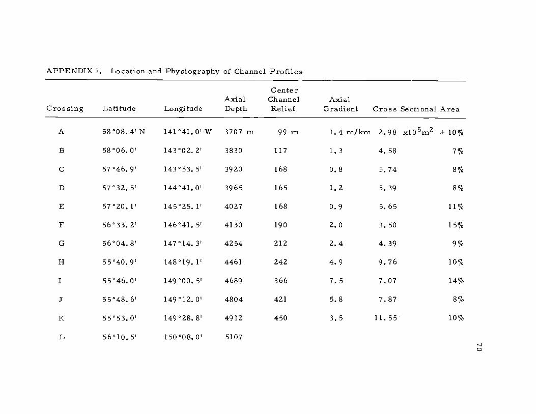
APPENDIX I. Location and Physiography of Channel Profiles
Crossing Latitude LongitudeAxialDepth
CenterChannelRelief
AxialGradient Cross Sectional Area
A 58008.41 N 141°41.0' W 3707 rn 99 m 1.4 rn/km 2.98 x10⁵m2 ± 10%
B 58°06.O' 143°02.2' 3830 117 1.3 4.58 7%
C 57°46.9' 143°53.5' 3920 168 0.8 5.74 8%
D 57°32. S 144°41. 0' 3965 165 1.2 5.39 8%
E 57°20.1' 145°25.1' 4027 168 0.9 5,65 11%
F 56033.21 146041.51 4130 190 2.0 3.50 15%
G 56°04.8' 147°14. 3' 4254 212 2.4 4.39 9%
H 55°40.9' 148019.1! 4461 242 4.9 9.76 10%
I 5504601 149°00.5' 4689 366 7.5 7.07 14%
J 55°486' 149°12.0' 4804 421 5.8 787 8%
K 55°530' 149°28.8' 4912 450 3.5 11.55 10%
L 56°lO.5' 150008.0I 5107-J

APPENDIX II. Transport Calculations from Channel
71
Profiles
h Asin p tan p (m)
1
(h sin f3 10 5m2 Q (h sinp)A
A .0014 99 .3722 2.98 1.11
B .0014 117 .4047 4.58 1.85
C .0009 168 .3888 5.74 2.23
D .0009 165 .3854 5,39 2.08
E .0009 168 .3888 5,65 2.20
F .0021 190 .6317 3,50 2.22
G .0021 212 .6672 4.39 2.93
H .0056 242 1.1641 9.76 11.36
I .0056 366 1.4316 7.07 10.12
J .0056 421 1.535 7.87 12.08
K .0056 450 1.652 11,55 19.08

72
APPENDIX III, Magnetic Stratigraphy of Core Y70-4-56
Sample Demagnetization SpecificDepth Level Intensity(cm) (oe) Declination Inclination (emu/cm3)
71- 74 0 324° 710 118
75 206 44 53
177- 179 0 53 76 22
75 186 45 11
277- 279 0 19 63 31
75 160 40 7
370- 372 0 351 67 22
75 186 39 5
459- 461 0 305 54 47
75 231 32 24
577- 579 0 289 70 23
75 210 36 12
674- 676 0 290 43 90
0 290 42 92
25 291 41 91
50 288 41 87
75 288 41 84
100 286 42 84
125 286 42 80

73
APPENDIX III (Continued)
SampleDepth(cm)
DemagnetizationLevel
(oe) Declination Inclination
SpecificIntensity
(emU/cm3)
674- 676 150 286° 43° 76
175 284 42 72
745- 747 0 304 61 95
75 236 31 53
859- 861 0 316 63 45
0 314 63 42
75 220 37 22
1051-1053 0 285 66 60
75 214 40 41
1151-1153 0 99 68 80
75 137 38 57
1258-1260 0 47 74 70
75 145 40 37
1464-1466 0 18 63 30
75 129 37 9
1567-1569 0 71 53 44
25 68 55 44
50 63 53 41
75 58 53 41

74
APPENDIX III (Continued)
Sample Demagnetization SpecificDepth Level Intensity(cm) (oe) Declination Inclination (emu/cm3)
1567-1569 100 115° 23° 26
125 126 26 21
150 109 27 24
1659-1661 0 130 73 37
0 118 75 32
75 156 40 20
1696-1698 0 230 -51 58
75 347 -44 19
1710-1712 0 355 -31 114
25 351 -30 115
50 351 -29 117
75 350 -30 117
125 343 -42 105
150 344 -44 101
1733-1735 0 240 -69 16
0 327 -45 14
75 320 -38 15
1751-1753 0 275 -34 32
0 282 -32 31
75 293 -21 32

APPENDIX IV. Alaskan Abyssal Plain Piston Core Locations and Descriptions
Core No. Latitude Longitude Length Description
Y70-2-35 55° 49.7'N 149° 10.9'W 400 cm
Y70-2-37 56° 08,5'N 147° 20.O1W 1211 cm
Y70-2-39 550 59.9'N 146° 24.3'W 1207 cm
Y70-2-40 56° 31.O'N 143° 48.9tW 988 cm
Y70-2-41 57° 10.2'N 141° 03,6'W 1151 cm
Lower channel axis core. Massive cleanmedium green and black sand throughout.
Lower channel north bank core. Massive,only occasionally laminated, medium green-gray silty clay. Two prominent sandmembers occur near the core bottom andone occurs at the very top.
Abyssal plain core south of lower channel.Medium gray silty clay with abundant siltlenses and two prominent sand membersnear top. One sand lens in lower half ofcore.
Abyssal plain core south of middle channel.Medium gray silty clay with abundant siltlenses and two prominent sand membersat top. Several closely spaced sand lensesin lower half of core.
Abyssal plain core south of upper channel.Medium gray silty clay with abundant sandlenses throughout. Upper two meters onlyfaintly laminated.
-JU.'

APPENDIX IV (Continued)
Core No. Latitude Longitude Length Description
Y70-3--48 58° 07.8'N 141° 40.9TW 537 cm
Y70-3-49 58° 10. 61N 141° 39.O'W
Y70-3-50 58° 06.1'N 141° 38.8'W
Y70-4-51 59° 05. OtN 143° 40.Z'W
590 cm
595 cm
588 cm
Y70-4-52 58° 54.6'N 143° 42.4'W 1128 cm
Upper channel axis core. Medium graysilty clay. Massive sand units up to 115 cmthick in upper half of core. 30 cm ofpebbles up to 7 mm at bottom of core.
Upper channel north bank core. Mediumgray clayey silt with abundant fine sandlenses throughout.
Upper channel south bank core. Mediumgray clayey silt with abundant fine sandlenses throughout.
Eastern Aleutian Trench axis core. Med-ium gray silty clay with occasional sandlenses.
Abyssal plain core near trench and lowercontinental slope. Medium gray silty claywith abundant sand lenses. Three sandmembers at top of core to 100 cm thick.
-J

APPENDIX IV (Continued)
Core No. Latitude Longitude Length Description
Y70-4-53 570 32.3'N 144° 43.O'W 417 cm Middle channel axis core. Massive non-laminated medium gray silty clay in upperhalf of core with several sand lenses inmiddle section. Massive fine sand membersup to 70 cm thick in lower half of core.:
Y70-4-54 56° 05. 2TN 140° 41. 3'W 1207 cm Abyssal plain core 200 km south of upperchannel. Medium gray silty clay withabundant silt lenses throughout.
Y70-4-56 53° 01.4'N 141° 41.4'W 1765 cm Central Alaskan Abyssal Plain core nearouter Baranof Fan. Medium gray mud withmany widely spaced silt lenses. Manyforam- rich zones and at least one ashlayer.
-J-J


![-dr[1]l o - Fisheries](https://static.documents.pub/doc/80x56/61cf46d30417fa701675aa97/dr1l-o-fisheries.jpg)


