London Cycling Design Standards
Draft for consultation, June 2014
Contents
1. Design requirements
2. Tools and techniques
3. Cycle lanes and tracks
4. Junctions and crossings
5. Cycle-friendly street design
6. Signs and markings
7. Construction, including surfacing
8. Cycle parking
Appendix
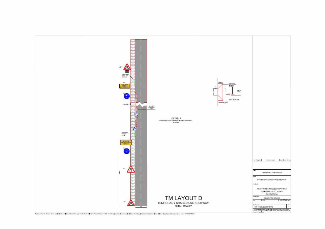
Cyclists at roadworks guidance

London Cycling Design Standards consultation draft – June 2014
Chapter 1 – Design requirements 1
Chapter 1
Design requirements
1.1 Raising standards 2
Using LCDS 3
Design outcomes 4
Guiding principles 7
1.2 Levels of service for cycling 13
Responding to context: street types 13
Cycling Level of Service assessment 16
1.3 Applying LCDS 17
Delivering high quality infrastructure 17
Legal and policy context 21

London Cycling Design Standards consultation draft – June 2014
Chapter 1 – Design requirements 2
1.1 Raising standards
1.1.1
The Mayor has set out his vision for cycling and his aim to make London a ‘cyclised’
city. Building high quality infrastructure to transform the experience of cycling in our
city and to get more people cycling is one of several components in making this
happen. This means delivering to consistently higher standards across London,
learning from the design of successful, well used cycling infrastructure and improving
substantially on what has been done before. It means planning for growth in cycling
and making better, safer streets for all.
1.1.2
Last published in 2005, the revised London Cycling Design Standards (LCDS) sets
out the approach needed in London to deliver this step-change in quality. Now
comprehensively updated to reflect established and emerging best practice, it is a
document that should inform design options and promote an integrated and
ambitious approach to delivering high quality infrastructure for cycling in all parts of
London.
1.1.3
LCDS identifies the design outcomes desired to deliver the ambitions of the The
Mayor’s Vision for Cycling (2013), reflecting the Mayor’s Roads Task Force report,
The Vision and direction for London’s streets and roads (2013). This requires that all
infrastructure delivered through TfL-funded programmes applies the following:
Guiding principles
These principles help clarify how the Mayor’s Vision for Cycling should be delivered.
Levels of service
These are ways of measuring the quality of design outcomes, both in terms of what
they offer for cycling and what they contribute to places.

London Cycling Design Standards consultation draft – June 2014
Chapter 1 – Design requirements 3
Summary of requirements
As described in more detail below, the requirements for cycling infrastructure
proposals delivered through the Mayor’s Vision for Cycling, are that they should:
1. demonstrate how the guiding principles have been reflected in design
decisions
2a. deliver the appropriate strategic level of service as defined by the Roads
Task Force street types approach
2b. meet the minimum standard expressed in the Cycling Level of Service
(CLoS) assessment, and any further programme- or project-specific
requirements
Using LCDS
1.1.4
London aspires to be a great cycling city. The application of the guiding principles set
out in this document and rigorous attention to achieving higher service levels as a
result of new infrastructure are central to this. Street types and the CLoS
assessment give the ability to set standards flexibly but consistently. Those planning
and delivering cycling infrastructure are encouraged through this guidance to be
bolder, to commit to making better, more attractive streets for cycling and walking
and to experiment with temporary measures where necessary to prove that change
is achievable. The overall aim is to plan and deliver a London-wide network for
cycling that meets with aspirations for infrastructure that is safe, comfortable, direct,
coherent, attractive and adaptable.
1.1.5
LCDS consists of comprehensive guidance to support meeting those aspirations,
and should be read and understood by all those involved in the design of
infrastructure for cycling and all those who help shape the street environment. It
carries no legal obligation, but gives advice on and options for the design and
delivery of infrastructure that will support the planned increase in cycling.
1.1.6
The first two chapters of LCDS cover general design requirements and techniques
for planning and delivering high quality infrastructure. The procedures set out here
should be applied in a way that is consistent and proportionate with the scale of
intervention proposed. The tools and techniques are intended to assist in delivering
the desired outcomes efficiently and to a high standard, rather than placing
unnecessary burdens on designers. The remaining six chapters of LCDS consist of
detailed design guidance to support the requirements and principles set out in
chapter 1.

London Cycling Design Standards consultation draft – June 2014
Chapter 1 – Design requirements 4
Figure 1.1 Structure of London Cycling Design Standards
Design outcomes
1.1.7
The six core design outcomes, which together describe what good design for cycling
should achieve, are: Safety, Directness, Comfort, Coherence, Attractiveness and
Adaptability. These are based on international best practice and on an emerging
consensus in London about aspects of that practice that we should adopt in the UK.
They are important not just for cyclists but for all users of streets, public spaces,
parks and riversides, where investment in cycling has the potential to improve the
quality of place.
1.1.8
These design outcomes, illustrated in figure 1.2, contribute to broader concepts of
placemaking, in particular the principles of good design set out in National Planning
Practice Guidance (2013) and local design guidance such as TfL’s Streetscape
Guidance (2009).
1. Design requirements
Good design outcomes for cycling
Guiding principles
Levels of service by street type
2. Tools and techniques
Cycling Level of Service assessment
Network planning
Scheme delivery
Maintenance
3. Cycle lanes and tracks
4. Junctions and crossings
5. Cycle-friendly street design
6. Signs and markings
7. Construction, including surfacing
8. Cycle parking

London Cycling Design Standards consultation draft – June 2014
Chapter 1 – Design requirements 5
Figure 1.2a Good design outcomes 1-3
1. Safety
Good infrastructure should
help to make cycling safer
and address negative
perceptions about safety,
particularly when it comes to
moving through junctions.
2. Directness
Routes must be logical and
continuous, without
unnecessary obstacles,
delays and diversions, and
planned holistically as part
of a network.
3. Comfort
Riding surfaces for cycling,
and transitions from one
area to another, should be
fit for purpose, smooth, well
constructed and well
maintained.
X
Space for cycling is
important but a narrow
advisory cycle lane next to a
narrow general traffic lane
and guard-rail at a busy
junction is not a safe offer
for the majority of cyclists.
X
This track works well on
links but requires cyclists to
give way at each side road.
Cyclists often choose to
stay on carriageway rather
than take fragmented
routes, with built-in delay.
X
Uncomfortable transitions
between on- and off-
carriageway facilities are
best avoided, particularly at
locations where conflict
with other road users is
more likely.
1.1.9
Success will be measured by the quality of design outcomes – how well
infrastructure performs in practice and the service level it provides. This is important
because growing cycling in London relies on attracting new cyclists as well as
providing better infrastructure for those who currently cycle. Improvement therefore
needs to be focused on the cycling experience: how safe and comfortable it feels,
how direct and attractive a journey is by bicycle, and whether cycle routes are
coherent and easy-to-follow.

London Cycling Design Standards consultation draft – June 2014
Chapter 1 – Design requirements 6
Figure 1.2b Good design outcomes 4-6
4. Coherence
Infrastructure should be
legible, intuitive, consistent
and understandable by all
users.
5. Attractiveness
Infrastructure should not be
ugly or add unnecessarily to
street clutter. Well designed
cycling infrastructure should
enhance the urban realm.
6. Adaptability
Cycling infrastructure should
be designed to
accommodate an increasing
numbers of users over time.
X
Neither cyclists nor
pedestrians benefit from
unintuitive arrangements
that put cyclists in
unexpected places away
from the carriageway.
X
Sometimes well-intentioned
signs and markings for
cycling are not only difficult
and uncomfortable to use,
but are also unattractive
additions to the streetscape.
X
Where streets have been
engineered primarily for use
by motor vehicles, as is
often the case with one-way
systems and gyratories, it is
difficult to make infra-
structure for cycling that is
legible and adaptable.
1.1.10
The future must not be like the past. Even infrastructure designed with good
intentions in mind can fail to provide a good level of service to cyclists, as the
examples in figure 1.2 show.

London Cycling Design Standards consultation draft – June 2014
Chapter 1 – Design requirements 7
Guiding principles
1.1.11
It will take consistent commitment to the quality and ambition of cycling infrastructure
design to realise The Mayor’s Vision for Cycling. The 20 guiding principles set out
below are fundamental to that approach and working through them can help
practitioners to understand what it will take to deliver the design outcomes. They are
geared towards learning from what has been done well in the past and tackling the
reasons why many previous attempts to deliver good cycling infrastructure have
fallen short.
Requirement 1:
Consideration of the guiding principles should shape the design of any infrastructure
delivered as part of the Mayor’s Vision for Cycling. How they are applied will depend
on site-specific conditions and on detailed design, but schemes should demonstrate
that these issues have been taken seriously and have informed design decisions.
1. Cycling is now mass transport and must be treated as such
Most current cycle provision is squeezed into spare space or on the margins of
roads. It reflects a belief, conscious or otherwise, that hardly anyone cycles, that
cycling is unimportant and that bikes must take no meaningful space from more
important road users, such as motor vehicles and pedestrians.
This no longer applies, especially in the centre. TfL’s April 2013 cycling census found
that 24 per cent of all rush-hour traffic in central London is bicycles, and 16 per cent
across the entire day, with shares of up to 64 per cent on some main roads. Similar
shares apply in inner London.
New cycle facilities must be designed to cope not just with these existing levels of
use, but with the future we are planning: of further increases in cycling in zones 1
and 2, and of existing inner-city cycling levels starting to spread to the suburbs.

London Cycling Design Standards consultation draft – June 2014
Chapter 1 – Design requirements 8
2. Facilities must be designed for larger numbers of users
In an era of mass cycling, facilities designed for minimal cycling will not work.
Hundreds of cyclists an hour will be using many of the busier main road cycle tracks
– sometimes already are. Tracks should ideally be 2 metres wide in each direction (4
metres for bidirectional tracks) to allow room to overtake. If this is not possible, faster
cyclists will ignore them. This should be the rule, though there will have to be some
exceptions.
People will cycle in growing numbers, whether other road users want them to or not.
The only issue is whether we cater for them effectively – reducing the potential for
conflict with others - or ineffectively.
3. Bicycles must be treated as vehicles, not as pedestrians
Cyclists and pedestrians should not be forced together where there is space to keep
them apart, creating unnecessary conflict which can only increase as the number of
cyclists rises.
We have a strong preference against schemes requiring cyclists and pedestrians to
share the same highway space, wherever they can be avoided. It will be necessary
to use some shared areas in our cycle routes, particularly where the space is wide,
but we will prefer to create delineated cycle tracks across it, perhaps with sloping,
pedestrian-friendly kerbs or different surfacing.
Cyclists and pedestrians should not share the same space at crossings and
junctions. Clearly-delineated separate and/or parallel routes should be provided for
cyclists and pedestrians. Typical bad cycle design deals with junctions by making
cyclists pretend to be pedestrians, bringing them on to the pavement and having
them cross the road, often in several stages, on toucan crossings.
London Cycling Design Standards consultation draft – June 2014
Chapter 1 – Design requirements 9
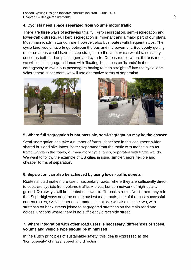
4. Cyclists need space separated from volume motor traffic
There are three ways of achieving this: full kerb segregation, semi-segregation and
lower-traffic streets. Full kerb segregation is important and a major part of our plans.
Most main roads in London are, however, also bus routes with frequent stops. The
cycle lane would have to go between the bus and the pavement. Everybody getting
off or on a bus would have to step straight into the lane, which would raise safety
concerns both for bus passengers and cyclists. On bus routes where there is room,
we will install segregated lanes with ‘floating’ bus stops on ‘islands’ in the
carriageway to avoid bus passengers having to step straight off into the cycle lane.
Where there is not room, we will use alternative forms of separation.
5. Where full segregation is not possible, semi-segregation may be the answer
Semi-segregation can take a number of forms, described in this document: wider
shared bus and bike lanes, better separated from the traffic with means such as
traffic wands in the roads, or mandatory cycle lanes, separated with traffic wands.
We want to follow the example of US cities in using simpler, more flexible and
cheaper forms of separation.
6. Separation can also be achieved by using lower-traffic streets.
Routes should make more use of secondary roads, where they are sufficiently direct,
to separate cyclists from volume traffic. A cross-London network of high-quality
guided ‘Quietways’ will be created on lower-traffic back streets. Nor is there any rule
that Superhighways need be on the busiest main roads; one of the most successful
current routes, CS3 in inner east London, is not. We will also mix the two, with
stretches on back streets joined to segregated stretches on the main road and
across junctions where there is no sufficiently direct side street.
7. Where integration with other road users is necessary, differences of speed,
volume and vehicle type should be minimised
In the Dutch principles of sustainable safety, this idea is expressed as the
‘homogeneity’ of mass, speed and direction.

London Cycling Design Standards consultation draft – June 2014
Chapter 1 – Design requirements 10
8. Cyclist interventions need not be attempted on every road
We have no intention of preventing cyclists from
using any road, save motorways. But some busy,
narrow main roads can never be made truly safe
for cyclists, and there is little point trying if better
alternative roads exist. In locations where a
number of roads run parallel, consider designating
different roads for different users.
9. Routes must flow
Routes must feel direct and logical. Users should not feel as if they are having to
double back on themselves, or go the long way round. Unnecessary small obstacles
and diversions should be removed. Chicanes and ‘cyclist dismount’ signs must be
avoided. Currently, many routes appear deliberately designed to break the flow.
10. Routes must be intuitively understandable by all users
Cyclists – and other road users – must be in no doubt where the cycle route runs
and where each different kind of user is supposed to be. This is partly about
waymarking, which must be frequent, clear and reassuring, guiding users at every
decision point and at some points in-between.
It is more, however, about design. Ambiguous or confusing designs, such as shared
use footways, schemes where the cycle route disappears, or schemes which funnel
cyclists unexpectedly into the path of other traffic, should be avoided.
11. Provision must be consistent and routes must be planned as a network
The worst routes tend to be the result of small, piecemeal interventions made in an
unconnected way. Ideally, schemes should be designed on a whole-route basis,
integrated with what you want to do for all users on the street. Even without this,
strenuous efforts should be made to avoid inconsistent provision, such as a track
going from the road to the pavement and then back on to the road, or a track which
suddenly vanishes.
Cycle facilities must join together, or join other things together. Routes should be
planned holistically as part of a network. Isolated stretches of route are of little value.
12. Routes and schemes must take account of how users actually behave. If
they do not, they will be ignored
They should respect people’s wishes to take the most direct route. There is little
point, for instance, in designing a cycle route through a road junction that requires

London Cycling Design Standards consultation draft – June 2014
Chapter 1 – Design requirements 11
cyclists to perform convoluted movements or wait at
multiple sets of crossings. If you do, they will simply
carry on using the motor traffic route. There is little point
in a route which takes cyclists too far out of the way to
be useful.
The ‘Cyclists dismount’ sign is the infallible mark of a
faulty cycle route. No-one wants to get off and walk.
Either the sign will be disobeyed, or the route will simply
not be used. If a route cannot be done without these
signs, it should not be done at all.
13. Many of the standard tools currently used to manage cyclists’ interactions
with others do not work
Chicanes and the like restrict the usefulness and capacity of a route, block the
passage of some types of bicycle, especially those used by disabled cyclists, and
create unnecessary conflict with other users funnelled into the same small space.
We certainly do not say that schemes should not tackle anti-social behaviour by
cyclists, which annoys and frightens many people. But they must do so in ways more
likely to succeed and to work for all parties.
To slow cyclists down at a pinch-point without compromising capacity or creating
conflict at a chicane, we suggest changing the surface to a material such as cobbles
or bonded gravel (though such materials should only be installed on short stretches,
not long links). Where cyclists need to be slowed right down, ridges can be installed.
14. Changes in road space can influence modal choice
Supply influences demand. Changing road space allocation can impact on modal
choice, as is clear from the experience of bus lanes in London. Within the framework
provided by the Roads Task Force street types, the network and route planning
process should identify where the most benefit is to be gained from reallocating road
space. This will help encourage more journeys by bicycle and support planning for
growing numbers of bicycle users.
15. Trials can help achieve change
If there is dispute about the impact of a road change, we recommend trialling it with
temporary materials. If it works, you can build it more permanently. If it does not, you
can easily and quickly remove or change it. However, it is important that the scheme
is got right at the beginning, to maximise the chances that it works.

London Cycling Design Standards consultation draft – June 2014
Chapter 1 – Design requirements 12
16. Avoid over-complication and the ‘materials trap’
Many UK road and public realm schemes, not just in cycling, waste large sums on
over-specified but essentially cosmetic alterations. Cycling interventions need not be
heavily engineered and costly. A lot of the best are simple and cheap – such as, for
instance, using a small number of bollards to create an entire cycle-only space.
The amount of work on a route should be proportionate to the level of intervention
proposed. There is no need to treat a light-touch backstreet route with the same level
of design, consultation and intervention as a Superhighway on a busy main road.
17. But do not be afraid of capital infrastructure
Sometimes, investing in more substantial
infrastructure is the only way to overcome a major
barrier. This can make or break a route, so it is
well worth exploring the value that a bridge or a
tunnel, for example, might add to a route.
18. All designers of cycle schemes must experience the roads on a bicycle
Ideally, all schemes would be designed by people who cycle regularly. But at a
minimum, anyone who designs a scheme must travel through the area on a bicycle
to see how it feels. We strongly recommend that designers and engineers also try
cycling on some existing facilities, to understand why they do or do not work.
19. As important as building a route itself is maintaining it properly afterwards
Road markings get dug up by utility contractors, ignored in repaints or just worn
away; tarmac is allowed to crack and part; tracks and lanes are seldom or never
swept, leaving them scattered with debris and broken glass. In winter, cycle lanes
are usually the last place on the road or pavement to be cleared of snow and ice, if
they are cleared at all.
All lanes must be properly maintained and swept frequently for debris and broken
glass. Route proposals must include a maintenance plan.
20. Know when to break these principles
Ideally, routes will be uninterruptedly excellent. In practice, where it is absolutely
unavoidable, we will accept a short stretch of less good provision rather than jettison
an entire route which is otherwise good. But we expect that this will be rare.

London Cycling Design Standards consultation draft – June 2014
Chapter 1 – Design requirements 13
1.2 Levels of service for cycling
1.2.1
The design outcomes articulated in this document do not come in the form of ‘cut-
and-paste’ layouts. The focus in delivering the Mayor’s Vision for Cycling should be
on the quality of the infrastructure delivered. This needs to be informed primarily by
the context and by sensitivity to end users’ needs. To address those issues, two
measures have been developed, aimed at defining what a good level of service for
cyclists means in practice. These aim to define both a strategic and a local level of
service.
Responding to context: street types
1.2.2
The first measure arises from the Roads Task Force, which established a framework
of nine street types (see figure 1.3) designated according to the relative significance
of movement and place within an area. ‘Movement’ is defined in terms of people
(and goods), not vehicles, whereas ‘place’ captures activities on the highway and the
relationship with frontages adjacent to the street. Urban streets are important both
for movement and place related activities so the framework provides a means of
associating traditionally competing demands for space. The adoption of street types
across neighbouring highway authorities will play an important role in providing a
unified view on where best to apply different measures.
Figure 1.3 Cycling infrastructure that may typically feature in each street type

London Cycling Design Standards consultation draft – June 2014
Chapter 1 – Design requirements 14
1.2.3
At a strategic level, street types should therefore be used to frame improvements to
support cycling and determine the strategic level of service required.
Requirement 2a:
Proposals for interventions to support cycling should refer to the RTF street types.
They should demonstrate that the provision made for cycling is appropriate for the
street type, referring where necessary to the indicative ranges set out in figure 1.4.
1.2.4
Street types classify the function of a location on the highway. A street’s
performance can be improved by implementing measures to better meet its
functional requirement. For example, the success of a high street may be improved
through the implementation of better cycling infrastructure and cycle stands to attract
trips. The level of service provided to a user is directly related to the type of activity
being promoted as appropriate for that location.
1.2.5
In locations with a higher place function, such as a town square, scheme design
might focus on how cycling can help to bring people into a space to dwell. This might
be more important for local high streets and squares than for city streets and city
places, where levels of pedestrian activity are likely to be high. Where through-
movement is dominant, design for cycling should address capacity and safety issues
such as cycle priority, avoidance of delay and managing conflict with motorised
vehicles.
1.2.6
TfL is developing a process that encourages agreement on street types with all
relevant stakeholders. This process will be repeatable, consistent and transparent
and involve officers from highway, planning and development authorities. A single
view of the network will be approved by appropriate representatives for the highway
authority and relevant London Council Committee members. Once approved, street
types will be mapped and available for reference via: www.tfl.gov.uk/street-types

London Cycling Design Standards consultation draft – June 2014
Chapter 1 – Design requirements 15
Figure 1.4 Indicative range of cycling interventions by RTF street type
1.2.7
In figure 1.4, types of cycling intervention are categorised according to the ‘degree of
separation’ they offer between cyclists and motor vehicles. Greater user separation
is needed where the movement function of a street leads to higher motorised traffic
speeds and volumes of traffic. Further detail and guidance on degree of separation
and different types of appropriate cycling provision are provided in chapter 3.
1.2.8
While it is important to ensure that cycle
intervention is appropriate for the street type,
shown indicatively in figure 1.4, it is also
important to provide continuity for cyclists
along a route. A strategic overview of a route
is required to ensure cycling provision is
seamless across street type boundaries. The
management of the interface between different
types of provision are important to ensure
cyclists retain a minimum level of service
across all of the nine street types.
Mandatory cycle lane on a ‘connector’

London Cycling Design Standards consultation draft – June 2014
Chapter 1 – Design requirements 16
Cycling Level of Service assessment
1.2.9
The second level of service measure for cycling operates at a more detailed level. A
Cycling Level of Service (CLoS) assessment has been developed in order to set a
standard for the performance of cycling infrastructure for routes and schemes, and
for individual junctions. The assessment is described in full in section 2.1. The
purpose of the CLoS assessment is to frame discussion about design options so that
schemes are appealing for existing cyclists and can entice new cyclists onto the
network. It may be used on any scheme that has an impact on the street
environment.
Requirement 2b:
The CLoS assessment describes a level of service that all schemes should meet.
This is based on existing policies and good design practice. Falling below the
minimum standard on the critical factors triggers the need for reassessment of the
scheme.
1.2.10
The assessment also provides an argument for how improvements for cycling could
be made in stages, trialling new layouts or different forms of traffic management
when it may be difficult to make the case for a permanent change. A closure to motor
vehicles, allowing filtered permeability for cyclists, may be a first stage of longer-term
area improvements, making streets better, safer places for all. The first stage
represents one intermediate level of service, the second a higher level.
Staged improvements for cycling at Palatine Road, Hackney

London Cycling Design Standards consultation draft – June 2014
Chapter 1 – Design requirements 17
1.3 Applying LCDS
1.3.1
The test of success will be whether the infrastructure that is delivered is high quality
and fit-for-purpose when built. It should achieve the six design outcomes – safe,
direct, comfortable, coherent, attractive and adaptable – and be shown to attain the
levels of service outlined in the previous section. This high standard will apply to the
delivery programmes set in motion by the Mayor’s Vision for Cycling and described
in this section.
Delivering high quality infrastructure
1.3.2
Cycle Superhighways provide radial, direct and safe cycle routes between outer and
central London, primarily aimed at commuter cyclists. Since the publication of the
Vision, the Superhighways concept has evolved so that routes will include greater
separation from motor traffic than was generally provided on the four existing
Superhighways (which will also be upgraded). This approach has been implemented
on the extension to CS2, and the new, substantially segregated East-West and
North-South routes, which will form important axes within the cycling grid for central
London.
The primary objectives for Superhighways as part of the cycle network are:
to improve conditions for existing commuters
to encourage more people to cycle
to improve the image and perception of cycling among Londoners, attracting
people who want to cycle and promoting good behaviour among all users
Full segregation on CS2 extension
Visualisation of the North-South route

London Cycling Design Standards consultation draft – June 2014
Chapter 1 – Design requirements 18
1.3.3
Core principles for physical measures implemented through the Superhighways
programme reflect the design outcomes.
Safety – infrastructure should improve safety, and the perception of safety,
along the whole route
Directness – Superhighways should follow direct routes into and across
central London; they are likely to be on main roads but do not have to be if a
sufficiently direct and viable quieter road is available
Comfort – road surface conditions should be improved and obstructions
minimised; the level of comfort should be maintained once the route is open
and in use
Coherence – Superhighways form an integral part of London’s cycle network
and will connect seamlessly with Quietways, local cycle routes and the
Central London Grid
Attractiveness – the whole route has a clear identity from beginning to end
with consistent and easy-to-follow road markings and signage
Adaptability – cycle lanes and tracks should be designed to accommodate
expected future increases in cycling volumes; wherever possible, cyclists will
be able to pass each other without having to move out into the motorised
traffic stream
1.3.4
Quietways will complement Superhighways by providing a network of cycling routes
through less heavily trafficked streets in every London borough, joining up with off-
carriageway routes where possible. Quietways will be direct, easy to follow and will
be delivered end-to-end, not piecemeal. They are not principally aimed at existing
fast, confident cyclists. They are aimed at new cyclists who want a safe,
unthreatening experience.
1.3.5
Quietways will mostly be radial, from central London to the suburbs, with some
orbital routes. They will be continuous, following cyclists desire lines. The vast
majority will be on more lightly trafficked back streets, with some on canal towpaths
or paths across parks and open spaces. At some points, for the sake of directness,
Quietways may need to join main roads, but this should be kept as brief as possible.
Where they have to join busier roads, or pass through busy, complicated junctions,
segregation should be provided.

London Cycling Design Standards consultation draft – June 2014
Chapter 1 – Design requirements 19
1.3.6
Quietways are low-intervention routes, with largely unsegregated cycling provision
because they are on quieter streets. The main interventions on the vast majority of
the network will be wayfinding, surfacing improvements, removing barriers such as
chicanes and improving the flow of the route. There may need to be some removal of
parking, but this will be kept to a minimum.
1.3.7
The Greenway and Quietway programmes have been merged. Many Greenways,
both existing and those now being delivered, will be used as part of the Quietway
network. But not all Quietways will be Greenways – the majority of Quietways will be
normal streets, not parks or canal towpaths.
1.3.8
Key principles for Quietways are as follows:
Routes should be on the quietest available roads consistent with directness.
Routes should be as straight and direct as possible.
Routes should try to avoid unnecessary turns.
At some points, for the sake of directness, Quietways may need to join main
roads, but this should be as brief as possible. Where they have to join busier
roads, or pass through busy, complicated junctions, segregation must be
provided.
Routes should use the same road in both directions unless it is absolutely
unavoidable. One-way streets should be made two-way for cyclists where this
is possible.
Right turns in traffic, which require cyclists to filter into the middle of other
vehicles, should be avoided wherever possible. Right turns on quiet roads are
acceptable.
Right turns which require cyclists to filter in busy traffic should always be
avoided. If it is unavoidable, a short stretch of segregation or other road
rearrangement should be provided.
Wayfinding will largely be on-carriageway, though signs will be necessary at
some junctions.
Routes need to operate full-time. Where routes are through parks that are
closed at night, then an acceptable and sufficiently direct alternative night
route, on similarly quiet roads, will need to be well signposted.
Partners should consider ‘social safety’ as a central and integral part of
Quietway design and delivery. Lighting and CCTV should be improved should
be improved where necessary.

London Cycling Design Standards consultation draft – June 2014
Chapter 1 – Design requirements 20
1.3.9
The three outer London Mini-Hollands will see cycling interventions that will
transform Enfield, Kingston-upon-Thames and Waltham Forest, and benefit other
town centres as areas with exemplar facilities for cyclists. This will result in an uplift
in safe cycling associated with excellent cycle facilities and public realm provision.
The emphasis is on transformational infrastructure measures, and the programme is
specifically targeted at capturing the potential for journeys by bicycle to replace many
journeys currently undertaken by private car.
1.3.10
The Mayor’s Vision for Cycling includes a revised Better Junctions programme.
Reflecting the commitment to make London’s busiest junctions safer and more
attractive for cyclists and other vulnerable road users, this will involve substantial
improvements to 33 junctions across London. This includes locations on existing and
proposed Cycle Superhighways.
1.3.11
Through the Cycle to School Partnerships initiative, clusters of schools will work with
their borough and the local community to identify barriers to cycling to school and
solutions for overcoming them. TfL will work with the Cycle to School Partnerships to
deliver pilots demonstrating a combination of infrastructural solutions and supporting
measures to overcome the barriers and enable safe cycling to school.
1.3.12
Improvements to infrastructure that can help support cycling are also made through
the existing TLRN Regional Improvement Programme schemes undertaken by TfL
and through Local Implementation Plan (LIP) schemes led by the boroughs and
cities.
1.3.13
This document also considers innovations currently being trialled, or planned for trial.
These practices are not yet established but have great potential to broaden
significantly the options we have for designing high quality infrastructure for cycling
in the future. They include:

London Cycling Design Standards consultation draft – June 2014
Chapter 1 – Design requirements 21
Dedicated traffic signal infrastructure for cyclists. Potential applications of low-
level signals are described in section 4.3.
Continuous and intermittent forms of separation of cyclists from motor
vehicles on links. Content on kerb segregated and light segregated cycling
facilities is provided in chapter 3.
Different ways of managing kerbside activity, including ‘floating’ parking,
loading and bus stops on the offside of cycle lanes/tracks. Sections 3.2, 5.4
and 5.5 cover these areas.
Ways of helping cyclists turn right from the nearside, without having to turn
across lanes of moving motor traffic. Two-stage right turns are described in
section 4.3.
Legal and policy context
1.3.14
Current policy on cycling in London is driven by the The Mayor’s Vision for Cycling
(2013) and by the Mayor’s Transport Strategy (2010). The latter sets a target for the
increasing the mode share for cycling to 5 per cent of all journeys by 2026. This will
represent a 400 per cent increase since 2001. Figure 1.5 below sets out other
important documents that form the policy context for cycling infrastructure, as well as
key legal and regulatory considerations.
1.3.15
In August 2013, the Prime Minister announced his ambition to increase cycling in
England from 2-3 per cent of trips in England towards the levels achieved in certain
other European countries where 10-15 per cent trips are commonly made by bike.
To achieve this, he challenged local authorities to raise the bar in designing and
delivering cycle-friendly infrastructure to encourage many more people to try cycling.
As part of the same announcement, it was indicated that the Department for
Transport may endorse the LCDS as best practice guidance for use by highway
engineers across England.
1.3.16
The Network Management Duty requires local traffic authorities to manage their
networks with a view to securing the expeditious movement of traffic on the
authority’s road network and facilitating the expeditious movement of traffic on road
networks for which another authority is the traffic authority (so far as may be
reasonably practicable having regard to their other obligations, policies and
objectives). In this instance, ‘traffic’ is explicitly defined as including pedestrians,
cyclists and motorised vehicles.

London Cycling Design Standards consultation draft – June 2014
Chapter 1 – Design requirements 22
Figure 1.5 Selected legal and policy context for cycling in London
Most relevant policy context Key aspects of legal and regulatory context
London-wide
Mayor's Vision for Cycling (2013)
Roads Task Force report, The Vision
and direction for London’s streets and
roads (2013)
The London Plan (2011)
Mayor’s Transport Strategy (2010)
Cycle Safety Action Plan (2014)
Cycle Security Plan (2010)
Clearing London's Air (2010), the
Mayor’s strategy for improving air
quality
Tree and Woodland Framework for
London (2005)
TSRGD
The Traffic Signs Regulations and General
Directions (2002, revised version out for
consultation 2014 and due to be adopted in
2015) sets regulatory requirements on
signs and road markings.
Highways Act (1980)
This Act places a statutory obligation on
highway authorities to provide for the safe
movement of people and goods.
Traffic Management Act (2004)
This gives additional responsibilities to local
traffic authorities to address the
shortcomings of the Highways Act and New
Roads and Streets Works Act, 1991,
particularly in relation to planning and co-
ordination of works and in establishing the
Network Management Duty.
Health and Social Care Act (2012)
This shifts more responsibilities onto local
authorities and enables more direct links
between health outcomes and local policies
in areas such as transport.
Crime and Disorder Act (2006)
Section 17 places a general responsibility
on local authorities to design out crime and
to take account of community safety plans.
Disability Discrimination Act (1995)
Equality Act (2010)
Construction Design and Management
regulations (2007)
CDM sets out the need for practitioners to
be adequately trained for the work they are
doing.
National
National Planning Practice Guidance
(2013)
All Party Parliamentary Cycling Group
(APPCG), Get Britain Cycling (2013)
Signing The Way (2011)
Local Transport Note LTN 2/08: Cycle
Infrastructure Design (2008)

London Cycling Design Standards consultation draft – June 2014
Chapter 1 – Design requirements 23
1.3.17
The Disability Discrimination Act 1995 (DDA) and the subsequent Equality Act 2010
require authorities to make reasonable adjustments to overcome physical barriers to
access. This should be done by removing or altering barriers, thereby enabling
people to avoid them or by providing access by an alternative means. This applies to
the street environment and to public transport services.
Cycle stands should not create new
hazards for pedestrians: use of on-
carriageway space for cycle parking
Seville, Spain: a reminder that wheelchair
users are welcome on cycle tracks

London Cycling Design Standards consultation draft – June 2014 24
Chapter 2 – Tools and techniques
Chapter 2
Tools and techniques
2.1 The Tube Network for the Bike 25
Overview 25
London’s cycling network strategy 26
Stakeholder involvement 28
Cycling Level of Service assessment 29
Junction assessment tool 33
2.2 Developing a coherent cycle network 36
Review of existing conditions 36
Mesh density analysis 38
Accessibility classification 40
Area porosity analysis 41
Cycling Level of Service audit 42
Example approaches to developing the network 44
Planning cycling into new development 46
2.3 Scheme delivery 49
Scheme stages 49
Traffic Regulation Orders for cycling schemes 52
Procedures for creating cycle tracks and shared use paths 53
2.4 Maintenance 54

London Cycling Design Standards consultation draft – June 2014 25
Chapter 2 – Tools and techniques
2.1 The Tube Network for the Bike
Overview
2.1.1
This chapter sets out network planning, route planning and implementation tools and
techniques, showing how planning, design and delivery are related. All the tools
described here are intended to serve the over-riding objectives of efficiently delivering
safer, more comfortable, direct, coherent, attractive and adaptable cycling
infrastructure. They should be applied in a proportionate manner.
The level of route delivery planning, design and stakeholder involvement needs to be
appropriate for the level of intervention proposed. Where there are limited changes to
be made, as is likely for large stretches of Quietway routes, then a minimal approach
should be taken and procedural demands should not be allowed to impede delivery.
2.1.2
The relationship between different techniques and procedures is shown in figure 2.1
below.
Figure 2.1 Overview of techniques and procedures for delivery cycle infrastructure
As appropriate through the process:
Stakeholder involvement
Cycling Level of Service assessment
Influencing other emerging schemes
NETWORK STRATEGY
NETWORK PLANNING & LAND USE PLANNING
ROUTE ASSEMBLY
SCHEME DELIVERY
MONITORING, MAINTENANCE, ENFORCEMENT

London Cycling Design Standards consultation draft – June 2014 26
Chapter 2 – Tools and techniques
London’s cycling network strategy
2.1.3
The network strategy for London is the development of the ‘Tube Network for the Bike’
approach described in The Mayor’s Vision for Cycling. Its application in London is geared
to enabling more people to cycle more safely, mindful of the expected growth in numbers
of cyclists. Routes and schemes that contribute to the network in outer London are aimed
at transforming cycling in areas where numbers of cyclists may be low or stable but where
there is great potential for further growth.
2.1.4
The elements that make up the network are:
Cycle Superhighways New Superhighways Upgrade of the four existing Superhighways
Quietways Central London Grid New Quietways in inner and outer London
Mini-Hollands Transformation of town centres and associated areas in three boroughs: Enfield, Kingston-upon Thames and Waltham Forest
2.1.5
Different approaches have been planned for areas of different cycling potential. Area-wide
infrastructure is appropriate for central London or specific outer London town centres,
where there is a high density of potential and existing cycle journeys. Outside these urban
centres, the cycling potential is less concentrated, so planned infrastructure such as
Superhighway or Quietway routes will be adapted accordingly.
Superhighways
2.1.6
The first four Superhighways brought about an average 77 percent increase in cycling on
the routes concerned – 30 per cent of those cycling trips are new or switched from another
mode. The contribution of the Cycle Superhighway programme to the overall network has
been revised in the light of the aspirations set out in the Mayor’s Vision for Cycling. Cycle
Superhighways in the new network will include upgraded versions of the existing routes
and new routes.

London Cycling Design Standards consultation draft – June 2014 27
Chapter 2 – Tools and techniques
2.1.7
The Cycle Superhighways programme has a large interface with the responsibilities of
London boroughs and others. In some cases, the route is on borough-owned roads and
there needs to be close working between TfL and the boroughs to obtain approvals and
buy-in to any proposals. Even where TfL is the highway authority, boroughs should still be
closely involved in the design process as the measures implemented are likely to have an
impact beyond the TLRN highway.
Quietways 2.1.8
Assessment criteria for prioritising potential Quietways routes, including those that form
part of the Central London Grid, are set out in figure 2.2. Routes should be assessed
against these measures as far as possible before final route selection and detailed design.
Figure 2.2 Quietways route prioritisation criteria
Network Prioritisation
contribution to a network – a geographical spread of routes that capture trip attractors and connect key points across London
deliverable along the entire length of a route over an agreed period
awareness of other schemes being delivered in the area that may influence phasing or impact the selected route
Directness and Cohesion
following cycle desire lines, public transport routes or routes used for short trips by car
connecting places of interest
minimising delays and avoiding unnecessary diversions (preferably using the same roads in each direction)
overcoming specific barriers to cycling, particularly at junctions
easy to navigate and homogeneous Attractiveness
avoiding or treating significant collision hotspots
secure and offering a feeling of safety
accessible at all times, or with a suitable ‘after-hours’ alternative
having priority at junctions/intersections/crossings (ideally)
making use of streets with limited traffic access (ideally) Traffic composition and impact to other users
minimising use of heavily trafficked roads (<3,000 PCUs per day)
with limited use by freight vehicles and other HGVs
having limited points of conflict with oncoming and crossing traffic, parked vehicles and loading bays
improving pedestrian facilities, if possible, and with the ability to manage movement through areas of heavy pedestrian use

London Cycling Design Standards consultation draft – June 2014 28
Chapter 2 – Tools and techniques
Buildability
known significant outstanding land ownership, access issues or ecological issues
with significant sections already to a good standard
limited requirement for signals work
practicality and cost effectiveness of any modification to junctions Political support
with support in principle for the entire route from the managing authority, senior officer and/or relevant Member
with agreement on alignments and improvements secured between all boroughs involved
Stakeholder involvement
2.1.9
Stakeholder support and consultation throughout the process is important for schemes to
be successful. They can provide valuable information and local knowledge during route
planning and scheme development. To be meaningful, it needs to be conducted at times
when it can positively influence outcomes without causing delay and done in a
proportionate manner. Stakeholder involvement has two distinct functions: incorporating
and responding to stakeholder interests, and keeping stakeholders informed of issues that
affect their interests.
2.1.10
Stakeholders are likely to include:
ward councillors and highway authority
TfL, including modal specific representatives such as buses and taxis and private hire
local employers and other generators (or potential generators) of significant cyclist movement, such as higher education establishments and hospitals
cycling organisations
freight industry representatives
groups with an interest in pedestrian accessibility
developers or landowners whose land may be affected or who may be asked to contribute to funding
residents, local amenity groups, conservation groups and English Heritage.

London Cycling Design Standards consultation draft – June 2014 29
Chapter 2 – Tools and techniques
Cycling Level of Service assessment
2.1.11
A Cycling Level of Service (CLoS) assessment has been developed in order to set a
common standard for the performance of cycling infrastructure for routes and schemes,
and for individual junctions. The purpose of the CLoS assessment is to frame discussion
about design options so that schemes are appealing for existing cyclists and can entice
new cyclists onto the network. It may be used on any scheme that has an impact on the
street environment.
2.1.12
As it is focused on ‘rideability’, the experience of cycling and the performance of links and
junctions, CLoS does not differentiate between street types. Infrastructure appropriate to
the street type is a prior consideration, although acceptable scoring ranges may need
adjustment by street type according to how programme-specific requirements are defined.
2.1.13
CLoS builds on the knowledge of existing systems such as the CIHT Cycle Audit and
Cycle Review, the London Cycling Campaign’s User Quality Audit and 'Love London, Go
Dutch' matrix and the Dutch 'Bicycle Balance' system. It does not replace any existing
audit system such as the Road Safety Audit, Non Motorised User Audit or Cycle Audit. It is
designed to raise issues already covered by regulatory and statutory documents rather
than introducing new requirements and can be used in conjunction with toolkits such as
PERS and FERS, the pedestrian and freight environment review systems.
2.1.14
Anybody can undertake the CLoS assessment but highway authorities or consultants
working within the industry are capable of giving extra quality assurance in using the tool.
The assessment is designed to promote discussion, and should be balanced with the
judgement of the engineer or planner involved.
2.1.15
The CLoS should fit into several stages of the lifecycle of a scheme:
at planning stage, it could help to identify issues, frame objectives and quantify benefits arising from potential improvements to inform a business case (by using existing economic evaluation procedures) – this particularly refers to route assessment and route prioritisation
at design brief stage, it could be used to give a baseline score for the existing conditions
at a preliminary design stage, several feasibility options could be measured against each other and the differences used to inform discussion with stakeholders
post-completion, it could help ensure that maintenance of the route remains a priority

London Cycling Design Standards consultation draft – June 2014 30
Chapter 2 – Tools and techniques
2.1.16
CLoS is based on the six design outcomes of safety, directness, coherence, comfort,
attractiveness and adaptability. It then breaks down each into specific factors. At the next
level of detail are indicators that can be used to measure performance against each factor.
For example, the ‘safety’ element contains three factors: collision risk, feeling of safety and
social safety. CLoS focuses on environments that would entice new cyclists to switch
journeys from other modes and maintain this modal shift for the long term.
2.1.17
As figure 2.3 shows, each indicator has a set of descriptions and score values – either 0, 1
or 2. The ‘basic’ level of service, or zero score, may trigger the need for improvement, but
this depends on the overall context of the route and of the project. Zero scores should be a
prompt for examining whether the factor in question will have a negative impact on the
propensity to cycle. Users are encouraged to set expectations that are ambitious while
also being achievable.
2.1.18
Certain factors also have ‘critical’ scores, which describe circumstances that should be a
cause for particular concern. Clients and designers must address these as a priority, even
if only to ‘lift’ them to a zero score – a scheme that registers as ‘critical’ on any one
indicator has not met the required standard for programmes and projects funded under the
Mayor’s Vision for Cycling. To be given greater weighting in the scoring system, it is
suggested that the 0, 1 or 2 scores for where critical factors are identified should be
multiplied by 3.
2.1.19
At the route planning stage, it is not likely that all factors can be measured, largely
because routes are likely to include many types of additional cycling provision. In this
case, factors that are of greatest importance and relevance at the network level should be
prioritised.

31 Figure 2.3 Cycling Level of Service assessment matrix (part 1)
Factor Indicator Critical Basic CLoS (score=0) Good CLoS (score=1, or 3 for critical indicators)
Highest CLoS (score=2, or 6 for critical indicators)
Max score
Safety
Collision risk
Left/right hook at junctions
Heavy streams of turning traffic cut across main cycling stream
Side road junctions frequent and/or untreated. Conflicting movements at major junctions not separated
Fewer side road junctions. Use of entry treatments. Conflicting movements on cycle routes are separated at major junctions
Side roads closed or footway is continuous. All conflicting streams separated at major junction
6
Collision alongside or from behind
Nearside lane in pinch point range 3.2 to 3.9m
Cyclists in wide (4m+) nearside traffic lanes or cycle lanes less than 2m wide
Cyclists in cycle lanes at least 2m wide
Cyclists with a high degree of separation from motorised traffic
6
Kerbside activity or risk of collision with door
Narrow cycle lanes <1.5m alongside parking/loading / no buffer
Frequent kerbside activity on nearside of cyclists / cycle lanes giving effective width of 1.5m
Less frequent kerbside activity on nearside of cyclists / cycle lanes giving effective width of 2m
No kerbside activity / Parking and loading on outside of cycling facility
6
Other vehicle fails to give way or disobeys signals
Reasonable visibility, route continuity across junctions and priority not necessarily clear
Clear route continuity through junctions, good visibility, priority clear for all users, visual priority for cyclists across side roads
Cycle priority at signalised junctions; visual priority for cyclists across side roads
2
Feeling of safety
Separation from heavy traffic
Cycle lanes 1.5-2m wide / ASLs at junctions
Cycle lanes at least 2m wide / some form of separation
Cyclists physically separ-ated from other traffic at junctions and on links
2
Speed of traffic (where cyclists are not separated)
85th percentile greater than 30mph
85th percentile greater than 25mph
85th percentile 20-25mph
85th percentile less than 20mph
6
Volume of traffic (where cyclists are not separated)
>1,000 vehicles / hour at peak
500 -1,000 vehicles / hour at peak < 5 per cent HGV or critical
200 - 500 vehicles / hour at peak, <2 per cent HGV
<200 vehicles / hour at peak
6
Interaction with HGVs Frequent, close interaction
Some interaction Occasional interaction No interaction 6
Social safety
Risk/fear of crime Risk is managed: no ‘ambush spots’, reasonable level of street maintenance
Low risk: area is open, and well designed and maintained
No fear of crime: high quality streetscene and pleasant interaction
2
Lighting Some stretches of darkness
Few stretches of darkness
Route lit thoroughly 2
Isolation Route generally close to activity, for most of the day
Route close to activity, for all of the day
Route always overlooked
2
Impact of highway design on behaviour
Seeks to controls behaviour in parts
Controls behaviour throughout
Encourages civilised behaviour: negotiation and forgiveness
2
Directness
Journey time
Ability to maintain own speed on links
Cyclists travel at speed of slowest vehicle/cycle ahead
Cyclists can usually pass traffic and other cyclists
Cyclists choose their own speed (within reason)
2
Delay to cyclists at junctions
Journey time slightly longer than motor vehicles
Journey time around the same as motor vehicles
Journey time less than motor vehicles (eg cyclists can bypass signals)
2
Value of time
For cyclists compared to private car use (normal weather conditions)
VOT only slightly greater than private car use value due to some site-specific factors
VOT equivalent to private car use value: similar delay-inducing factors and convenience
VOT less than private car use value due to attractive nature of route
2
Direct-ness
Deviation of route (against straight line)
Deviation factor 35-50 per cent
Deviation factor 20-35 per cent
Deviation factor <20 per cent
2
Coherence
Connec-tions
Ability to join/leave route safely and easily
Cyclists do not have to dismount to connect to other routes
Cyclists can connect to other routes relatively easily
Cyclists provided with have dedicated conn- ections to other routes
2
Density of other routes
Network density mesh width >400m
Network density mesh width 250 - 400m
Network density mesh width <250m
2
Way-finding
Signing Basic road markings provided
Some signs and road markings, making it hard to get lost
Consistent signing of range of routes and destinations at decision points
2

32 Figure 2.3 Cycling Level of Service assessment matrix (part 2)
Factor Indicator Critical Basic CLoS (score=0) Good CLoS (score=1, or 3 for critical indicators)
Highest CLoS (score=2, or 6 for critical indicators)
Max score
Comfort
Surface quality
Defects: non cycle friendly ironworks, raised/ sunken covers/gullies
Major defects Some localised defects but generally acceptable
Minor defects only Smooth high grip surface
6
Surface material
Construction: asphalt concrete, HRA or blocks/bricks/sets
Hand laid asphalt; no unstable blocks/sets
Machine laid asphalt concrete or HRA; smooth blocks
Machine laid asphalt concrete; smooth and firm blocks undisturbed by turning vehicles
2
Effective width without conflict
Allocated riding zone range. Lane allocation each direction
<1.5m Superhighway <1.2m elsewhere
1.5-2.0m Superhighway 1.2-1.5m elsewhere (or 3-3.2m shared bus/cycle lane)
2.0-2.5m Superhighway 1.5-2.0m elsewhere (or 4.0m+ bus lane)
>2.5m Superhighway >2m elsewhere
6
Gradient Uphill gradient over 100m
>5 per cent 3-5 per cent <3 per cent 2
Deflect-ions
Pinch points caused by horizontal deflections
(Remaining) lane width <3.2m
(Remaining) lane width >4.0m
Traffic is calmed so no need for horizontal deflections
2
Undu-lations
Vertical deflections Round top humps Sinusoidal humps No vertical deflections 2
Attractiveness
Impact on walking
Highway layout, function and road markings adjusted to minimise impact on pedestrians
Largely achieves Pedestrian Comfort Level (PCL) B but C in some high activity locations
No impact on pedestrian provision / PCL never lower than B
Pedestrian provision enhanced by cycling provision / PCL A
2
Greening Green infrastructure or sustainable materials incorp-orated into design
No greening element Some greening elements Full integration of greening elements
2
Air quality PM10 & NOX values referenced from concentration maps
Medium to High Low to Medium Low 2
Noise polution
Noise level from recommended riding range
>78DB 65-78DB <65DB 2
Minimise street clutter
Signage and road markings required to support scheme layout
Little signage in excess of regulatory requirements
Moderate amount of signage, particularly around junctions
Minimal signage, eg. for wayfinding purposes only
2
Secure cycle parking
Ease of access to secure cycle parking within businesses and on street
Minimum levels of cycle parking provided (ie to London Plan standards)
Some cycle parking provided above minimum, to meet current demand, and attention to quality and security
Cycle parking is provided to meet future demand and is of good quality, securely located
2
Adaptability
Public transport inte-gration
Smooth transition between modes or route continuity maintained through interchanges
No additional consideration for cyclists within interchange area
Cycle route continuity maintained through interchange and some cycle parking available
Cycle route continuity maintained and secure cycle parking provided. Transport of cycles available.
2
Flexibility Facility can be expanded or layouts adopted within area constraints
No adjustments are possible within constraints. Road works may require some closure
Links can be adjusted to meet demand but junctions are constrained by vehicle capacity limitations. Road works will not require closure; cycling will be maintained although route quality may be compromised to some extent
Layout can be adapted freely without constrain to meet demand or collision risk. Adjustments can be made to maintain full route quality when roadworks are present
2
Growth enabled
Route matches predicted usage and has exceedence built into the design
Provision copes with current levels of demand
Provision is matched to predicted demand flows
Provision has spare capacity for large increases in predicted cycle use
2
TOTAL (max 100)

London Cycling Design Standards consultation draft – June 2014 33
Chapter 2 – Tools and techniques
2.1.20
User satisfaction surveys can be particularly useful for capturing some of the more
subjective judgements in the assessment. It is important to make a clear connection
between the needs of the local users and the reasons for making certain design decisions.
As figure 2.3 shows, subjective safety – therefore the perception of risk – is a key factor in
measuring the fitness-for-purpose of a cycling facility, even where the collision history of a
location, for example, might indicate that the objectively measured risk is low.
2.1.21
The impact on walking is a critical element in the assessment, even though it may not be
directly linked to level of service for cyclists. A Pedestrian Comfort Assessment, as
described in TfL’s Pedestrian Comfort Guidance, should be used as in the CLoS to provide
an objective rating for the balanced profile.
Junction assessment tool
2.1.22
As collisions tend to be clustered around junctions, a supplementary process for assessing
junctions has been developed. This may be used to inform a broader assessment of a
given location, or in order to inform scoring of the collision risk criteria in the CLoS
assessment.
2.1.23
Rather than going through the entire CLoS assessment for each possible movement of a
cyclist through a junction, an estimation of potential conflict can be done through briefly
assessing each of the potential movements in turn and marking them on a plan of the
junction, as shown in figure 2.4. Each movement can be rated ‘red’, ‘amber’ or ‘green’
according to how safely and comfortably it can be made by cyclists:
where conditions exist that are most likely to give rise to the above collision types, then the movement should be represented on the plan as a red arrow
where the risk of those collision types has been reduced by design layout or traffic management interventions, then the movement should be coloured amber
where the potential for collisions has been removed entirely, then the route should be coloured green
‘green’ should be taken to mean suitable for all cyclists; ‘red’ means suitable only for a minority of cyclists (and, even for them, it may be uncomfortable to make)
2.1.24
Any banned movements for cyclists should be shown in black with a cross at the end.
Movements that can be made but would involve a particularly high level of risk to the
cyclist should be noted with a red cross at the end. These are movements that most cycle
trainers would advise against making.

London Cycling Design Standards consultation draft – June 2014 34
Chapter 2 – Tools and techniques
Figure 2.4 Example assessment for a generic junction
Ahead movements in two directions are aided by lanes marked through junctions and have been marked as green.
The street at the top is one-way – showing the banned cycling movements highlights a potential need to open it up to contraflow cycling.
The three possible right turns are all relatively difficult to make, being opposed turns, although ASLs help in each case.
In two cases, the pedestrian crossing island on the opposite arm gives some protection for right-turning cyclists from opposing traffic, so these have been scored as amber.
However, the right turn from the arm at the bottom scores a red because it would be hard for a cyclist to find a safe waiting place while ahead and right-turning traffic emerges from the one-way street.
2.1.25
For ‘red’ movements, one solution might be to enable the movement at a location away
from the main point of potential conflict, but there may be many different ways of
reconfiguring the junction to provide better and safer provision for cyclists (see chapter 4
for more details on junction design).
2.1.26
To help in comparing options, a score can be given based on each movement: 0 for red, 1
for amber and 2 for green. In this way, a total can be generated for the junction, or even for
individual routes through the junction (if it is the case that one route or movement for
cyclists is a significantly higher priority than another). The highest possible score for a
crossroad junction would be 24 and for a T-junction 12. In order to help assess junction
movements, figure 2.5 suggests typical scenarios that might lead to a ‘red’, ‘amber’ or
‘green’ rating.

London Cycling Design Standards consultation draft – June 2014 35
Chapter 2 – Tools and techniques
Figure 2.5 Indicative criteria for scoring junction assessments
Factors needing removal or mitigation
Possible improvements Further improvements
RED AMBER GREEN
Heavy left turn movement with high HGV mix
Opposed right turns with general traffic accelerating quickly into opportunistic gaps
Left slip lane
Guard-railing
Large junction radii
High speed motor traffic through junction
Uphill gradients
Wide junction crossings
No clear nearside access
Multiple lanes
Entry treatment at side road junction
Continuation of lane across junction
Right-turn protected island
Tight corner radii; pinch points removed (avoiding nearside lane of 3.2-3.9m)
Bus lane of 3.0-3.2m or of 4.5m or more
2m wide central feeder lane
ASLs (preferably 5m+ deep)
Signal adjustments to cycle movements
Left turn ban for general traffic
Opposing right turn banned for general traffic
Physically protected turn
Left bypass of signals
Segregation of cycle movements using dedicated cycle signals
Raised tables
Area-wide speed limit/reduction
2.1.27
The CLoS assessment also provides an argument for how improvements for cycling could
be made in stages. A closure to motor vehicles, allowing filtered permeability for cyclists,
may be a first stage of meeting longer-term objectives for area improvements, making
streets better, safer places for all. The first stage represent one intermediate level of
service, the second a higher level.

London Cycling Design Standards consultation draft – June 2014 36
Chapter 2 – Tools and techniques
2.2 Developing a coherent cycle network
2.2.1
This section covers examples of techniques that can be used to help network planning.
Step-by-step it covers the full process for planning a network for cycling, taking into
account urban form and land use as well as street types and route characteristics – as
summarised in figure 2.6. In reality, some of the network is likely to be in place (but may be
in need of upgrading) and some of the analysis may already exist, so these steps are not
requirements in route planning and scheme development. They are presented here as
helpful techniques that may be applied to support the development of a coherent network
and that could be used in communicating what a good network for cycling looks and feels
like.
Figure 2.6 Planning a cycle network from the beginning
Review of existing conditions
2.2.2
Figure 2.7 shows a typical London street layout with a railway line, a canal, a park and
different road classifications such as connectors, high roads, high streets, city streets, city
places and local roads. These are suggested by the road thickness and frontages.
Character buildings and major trip generators have also been highlighted. Proposals for
cycling should reflect the character of an area and the movement and place functions of its
streets. Cycling infrastructure should improve the quality of streets and so coherent
network planning needs to be sensitive to its surroundings.
Review existing conditions
Mesh density analysis
Classification audit
Porosity analysis
Cycling Level of Service assessment

London Cycling Design Standards consultation draft – June 2014 37
Chapter 2 – Tools and techniques
2.2.3
Overlaid on the street plan is a 400m by 400m grid: this is also the standard mesh density
sought for cycle networks in central London, as referenced in the CLoS. The coloured lines
show the existing cycle networks. In this case, the red route forms part of the national
cycle network which spans the UK and, in some cases, joins up with the international
EuroVelo network. It should be recognised that this network has a strategic importance
and any changes to it could affect many users. The blue routes shown are local routes that
may well have been developed as part of the London Cycle Network programme and so
may serve a strategic function as part of long-held desire lines for cyclists. Routes of this
type can date back many years, may be best considered for future network adoption and
often already feature cycle-friendly interventions. The green route shows a route along a
canal towpath that may form part of the greenway network. This route may not be suitable
for all types of cyclists, particularly commuter cyclists, but could form a part of the area
cycle network due to its attractive, traffic-free condition.
2.2.4
In any area the remnants of previously planned strategic cycle networks should be evident
and these should be referenced on the base plan so that gaps or other failures can be
assessed. It is important to view routes in context and incorporate cycling within the unique
layout of the area without compromising strategic network considerations such as
coherence and directness. At all stages of this process, it is also important to source up-to-
date and accurate information.
Figure 2.7 Existing context showing base network
Key
London Cycling Design Standards consultation draft – June 2014 38
Chapter 2 – Tools and techniques
Method
briefly assess place characteristics: natural features, key constraints (eg waterways or railways, including bridging points), local centres, land uses, trip generators (see figure 2.17 for a fuller list)
identify key trip generators, active frontages, character buildings
classify roads based on RTF street types (or refer to street type maps where this work has already been done)
overlay existing cycle networks, including strategic and local routes
Analysis
look for gaps in the existing cycle networks
look to see if cycling provision is appropriate for the RTF street type
look for desire lines between trip generators
identify character areas and heritage areas
Mesh density analysis
2.2.6
In a properly joined-up cycle network, cyclists should not have to travel more than 400m to
get to a parallel route of similar quality. As referenced in CLoS, this attribute of a cycle
network is known as ‘mesh density’: it describes whether the grid of cycle routes is tighter
(with more route choice) or looser (less extensive).
2.2.7
Analysis of mesh density is best undertaken with GIS software and there are two main
methods to follow – see figure 2.8. The first involves dividing the area into cells and
measuring the length of cycle network in each cell. A 1km by 1km cell should have 4km of
cycle network. The second method involves starting with the cycle network and its routes
and measuring the size of the areas bounded by the routes. An area of 160,000sqm would
be present inside a 400m by 400m mesh and so this can be used as the standard to
measure against. Smaller areas should show as hotter on the heat map (reds and
oranges) as there is more coverage than required and higher areas should show as cooler
(blues) as there is not enough coverage.
2.2.8
Sections of network that run across major barriers to cycling, such as major untreated
junctions and gyratory systems, should not be counted in either method. The data used in
the Transport for London Cycle Guides represents the best available picture of cycle
routes in London but local authorities may have more up-to-date information about the
condition and extent of local networks.

London Cycling Design Standards consultation draft – June 2014 39
Chapter 2 – Tools and techniques
Figure 2.8 Heat map representation of the density
Cell example
Area bound example
2.2.9
Figure 2.9 shows a heat map representation of the density of routes in the study area. The
analysis highlights in yellow the ‘cooler’ areas, with poorer cycle network coverage. The
‘hotter’ red areas have a lower mesh density: less distance between parallel routes. This
type of analysis can be used to test the impact of planned interventions and can be run
after networks have been extended to test even coverage.
Figure 2.9 Mesh density heat map
Key

London Cycling Design Standards consultation draft – June 2014 40
Chapter 2 – Tools and techniques
Method
assess cycle networks for major barriers
load cycle network data into
overlay existing cycle networks, strategically planned and local routes
highlight bridges, natural features and constraints
Analysis
look for areas of low network coverage and identify potential route options
look for areas of high network coverage and identify most strategic alignments
Accessibility classification
2.2.10
Figure 2.10 shows a reclassification of every road in the area based on the level of
experience needed to ride it comfortably. Primary roads (coloured red) suggest a high
level of confidence, secondary roads (amber) are cyclable in comfort by most cyclists and
routes free of motorised traffic (green) are suitable for cyclists of any age and experience.
The majority of London’s roads are secondary and so are rideable but certain primary
roads can be intimidating for new cyclists and so it is important to identify these. Local
knowledge and the input of cycle trainers within the authority should help identify the
correct classifications. The main determinants are street types, speed and volume of
traffic, mix of vehicle types and the extent to which cyclists are required to integrate with
general traffic and perform manoeuvres whilst in traffic.
2.2.11
This red, amber and green approach can also be taken to assessing crossings in the area.
The difference between primary and secondary crossings of primary roads is particularly
important in network terms as cyclists tend to migrate towards the more comfortable
crossing conditions. Local cycling stakeholders should be able to provide information
about where these pleasant crossings are located if resources are not available to do a full
network audit. Ordnance Survey GIS systems also provide this data.
Method
Assess all links on the network to determine level of experience needed to cycle in comfort
Highlight comfortable secondary crossings of primary roads
Analysis
Look for potential new crossing sites, bearing in mind the benefits that can be secured for other users as well as cyclists (ensuring a balanced approach)
Look for areas dominated by primary roads and consider interventions

London Cycling Design Standards consultation draft – June 2014 41
Chapter 2 – Tools and techniques
Figure 2.10 Accessibility classification of road network
Key
Primary Secondary Routes free of motorised traffic
Area porosity analysis
2.2.10
Area porosity is a measure of how many places there are for cyclists to enter, pass
through and leave an area comfortably. A location that is ‘porous’ is a space that cyclists
can pass through with ease and comfort – usually a junction. If the porosity of an area is
high, then overall it is very permeable for cyclists (but often less so for other vehicles).
Figure 2.11 shows areas bound by primary roads. Comfortable (porous) secondary
crossings are shown as gateways as these effectively open up areas to less confident
cyclists. The provision of a gateway crossing can enable many square kilometres of route
options to be opened up and also serve as key navigational points across areas.
2.2.11
Where areas are bound by primary roads and have no gateways, then they are coloured
red. Where they have one gateway they are coloured amber and where then have two
they are coloured green. Rather than focussing on routes, this method shows the porosity
of an area by highlighting different crossing options on different streets. This approach is
particularly useful when planning routes to schools as it allows children and their parents
to be clear about the standard of roads they will encounter and where key crossings are.

London Cycling Design Standards consultation draft – June 2014 42
Chapter 2 – Tools and techniques
Method
Create areas bound by primary roads
Gather information as to where the current comfortable secondary crossings and access points are
Colour in bounded area based on the number of access points
Analysis
Look for areas that are effectively cut off as they are bound by busy primary roads
Assess where the likeliest new crossing can be provided into an area
Identify where access is needed for maintenance (for vehicles carrying out maintenance works)
Plan adjustments to networks to incorporate gateways, mindful of the directness design outcome
Figure 2.11 Area porosity analysis showing areas bound by primary roads and number of gateways
Key
Cycling Level of Service audit
2.2.12
Figure 2.12 shows road classification based on the Cycling Level of Service. This takes
time to complete in full but gives a comprehensive baseline of the rideability of the streets
in an area. Routes that fall below the standards stipulated in the CLoS should be
considered for upgrading or, if constraints are too great, then this approach can highlight
alternative alignments. The red, amber and green colouring is likely to look similar to the
accessibility classification system: this approach, based on the key design outcomes, adds
a greater level of sophistication, should it be required. Note that the value ranges may

London Cycling Design Standards consultation draft – June 2014 43
Chapter 2 – Tools and techniques
need to be adjusted according to specific programme requirements. On the example in
figure 2.12, the greenway route along the canal is rated as amber in CLoS as there may
be concerns about social safety, connections, effective width and lighting.
2.2.13
Potential strategic routes in the chosen area may require substantial investment, which
may need detailed justification. It is important that the junction assessment tool is used on
all junctions along planned strategic network routes and where cycle routes pass across
busier roads. If multiple roads are assessed, then the effect of area traffic management
improvements can be measured against the established baseline. This method is the most
time-consuming but helps collect vital information to underpin scheme prioritisation and
area traffic network strategies.
Method
Use the CLoS and junction assessment tool to assess the area network or focus on particular established or planned strategic routes
Analysis
Look where best conditions are and assess whether these can be connected to form routes
Assess potential for upgrading junctions to higher CLoS standards
Assess the standard of existing networks routes and look for potential improved alignments
Figure 2.12 Cycling Level of Service indicative ratings for network links and key nodes
Key

London Cycling Design Standards consultation draft – June 2014 44
Chapter 2 – Tools and techniques
Example approaches to developing the network
2.2.14
These tools can help identify where interventions would make the whole area accessible to
all cyclists. To develop this into a strategy, there are two main options: area-based
approaches and route-based approaches. The examples below describe how the
application of these strategic approaches may work in practice. In both cases, working
through the detail involves engaging with the impact on all modes and considering existing
on-street infrastructure and the potential for improving it for a broader range of users.
Area option – filtered permeability
2.2.15
Figure 2.13 shows a potential intervention that takes an area-based approach to improving
conditions for cycling by removing through motor traffic in zoned areas around a traffic-free
centre. Motorised traffic can enter and leave the zones but cannot pass between them
without using the primary routes or alternative roads outside the zones. Cyclists can pass
freely through motorised traffic restrictions between zones and so are favoured in terms of
journey time and convenience. Residents benefit from removal of through-traffic and their
homes can still be served by deliveries and parking. Most motorised vehicle movements
will be made by residents themselves. The general level of traffic is reduced to such an
extent that the CLoS scores are improved on all roads dramatically without the need for
cycle-specific infrastructure. This is a bold approach but delivers a high level of service for
cycling in a cost-effective manner.
Figure 2.13 Filtered permeability area treatment example
Key

London Cycling Design Standards consultation draft – June 2014 45
Chapter 2 – Tools and techniques
2.2.16
This approach has no obvious cycling facilities to entice new cyclists but is a method
employed by many towns and cities with high mode shares for cyclists. The London
Borough of Hackney has implemented this approach in certain areas and has the highest
modal share for cycling in London. Other cities and towns have used features such as
rivers and railway lines to divide areas into zones. If quick and easy access for pedestrians
and cyclists are implemented across these barriers then these modes will flourish, while
motorised traffic has to take longer, more circuitous routes.
Route option – network delivery
2.2.17
Figure 2.14 shows a route-based approach, where networks have been expanded,
connected and revised based on the five-step analysis. In the example, major
interventions such as a full junction redesign on a connector road where a Superhighway
meets a Quietway have been proposed as well as a new bridge link allowing a Quietway to
continue within the stipulated mesh density range. Land purchase has been suggested
through some private land acquisition to the south-east of the town centre, enabling two
Quietways to connect. New parallel secondary crossings have also been proposed to
increase area porosity.
Figure 2.14 Network delivery route treatment example
Key

London Cycling Design Standards consultation draft – June 2014 46
Chapter 2 – Tools and techniques
2.2.18
Some of the interventions are likely to be costly but justification can be made with
reference to the five-step process. This presents a logical, best practice assessment of an
area’s cycling potential and clearly points out network deficiencies and potential
improvements.
2.2.19
Cycle networks are often planned at a strategic, city-wide level but this process shows how
these can be adjusted locally to reflect the character, constraints and opportunities of the
surrounding area. Each local authority should incorporate these approaches into their area
planning strategies and this should lead to the mainstream establishment of cycling as a
viable mainstream transport option in line with the Mayor’s Vision.
Planning cycling into new development
2.2.20
The cycling network strategy should be an important influence on the planning of larger
development areas and should be integrated into authority- and area-wide spatial planning
frameworks as well being reflected in site-specific proposals. Figure 2.15 summarises how
the cycling design outcomes might be addressed in these plans and strategies.
2.2.21
Cycling infrastructure cannot be fitted into the streets of a new development once it has
been designed. High quality cycling provision must be designed into all new development
from the beginning. This does not mean token cycle parking, token painted separation on
footways or token advanced stop lines. It means designing new developments so that the
way cyclists move through the development meets the standards set down in this
document from the moment the first residents or tenants move in.
2.5.22
TfL’s online Transport Assessment Guidance tool describes the purpose and content of
transport assessments as part of the planning application process. This deals with areas
such as consideration of pedestrian and cycle linkages, trip generation, modelling and
impact. It is important to establish that access for cyclists to and through a development
will be provided to a desired quality. This is likely to require the input of cycling officers to
the development control process. Through pre-application discussions, the application
stage and enforcement, the planning process should ensure that proposals meet policy
requirements, that they are fit for purpose for the proposed site and development, and that
they are implemented as planned.
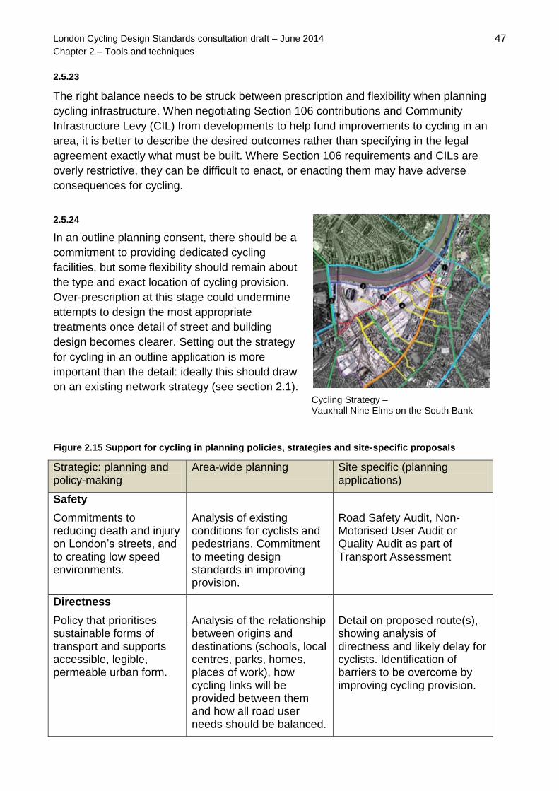
London Cycling Design Standards consultation draft – June 2014 47
Chapter 2 – Tools and techniques
2.5.23
The right balance needs to be struck between prescription and flexibility when planning
cycling infrastructure. When negotiating Section 106 contributions and Community
Infrastructure Levy (CIL) from developments to help fund improvements to cycling in an
area, it is better to describe the desired outcomes rather than specifying in the legal
agreement exactly what must be built. Where Section 106 requirements and CILs are
overly restrictive, they can be difficult to enact, or enacting them may have adverse
consequences for cycling.
2.5.24
In an outline planning consent, there should be a
commitment to providing dedicated cycling
facilities, but some flexibility should remain about
the type and exact location of cycling provision.
Over-prescription at this stage could undermine
attempts to design the most appropriate
treatments once detail of street and building
design becomes clearer. Setting out the strategy
for cycling in an outline application is more
important than the detail: ideally this should draw
on an existing network strategy (see section 2.1).
Cycling Strategy – Vauxhall Nine Elms on the South Bank
Figure 2.15 Support for cycling in planning policies, strategies and site-specific proposals
Strategic: planning and policy-making
Area-wide planning Site specific (planning applications)
Safety
Commitments to reducing death and injury on London’s streets, and to creating low speed environments.
Analysis of existing conditions for cyclists and pedestrians. Commitment to meeting design standards in improving provision.
Road Safety Audit, Non-Motorised User Audit or Quality Audit as part of Transport Assessment
Directness
Policy that prioritises sustainable forms of transport and supports accessible, legible, permeable urban form.
Analysis of the relationship between origins and destinations (schools, local centres, parks, homes, places of work), how cycling links will be provided between them and how all road user needs should be balanced.
Detail on proposed route(s), showing analysis of directness and likely delay for cyclists. Identification of barriers to be overcome by improving cycling provision.

London Cycling Design Standards consultation draft – June 2014 48
Chapter 2 – Tools and techniques
Strategic: planning and policy-making
Area-wide planning Site specific (planning applications)
Comfort
Linking air quality and environmental improvements to shifts from motorised forms of transport.
Requirements on level of service to be provided on identified routes. Evidence of responding to identified future demand for cycling.
Sufficient detail to allow analysis of effective width, gradient, deflections and capacity and surface quality. Should describe impacts on pedestrian comfort (using TfL’s Pedestrian Comfort Guidance).
Coherence
Commitment to sustainable forms of development and good integration between transport modes.
A hierarchy of streets and routes that clearly shows a joined-up, legible network for cycling.
Details of how proposals contribute to the development of a coherent network in the wider area.
Attractiveness
Recognition of the benefits of more people walking and cycling and interventions that promote better places for all. Provision of good quality, well located, secure cycle parking to help support growth in cycling.
Design guidance or code that deals with public realm quality – for example, setting out indicative street types that clearly how show good provision for cyclists will be provided. This should include indicative locations and quantity of cycle parking.
Detailed proposals for materials, cycle parking, other street furniture, signage, landscaping, management arrangements and maintenance costs.
Adaptability
Provision for measuring and monitoring strategic outcomes on cycling (eg route use, vehicle volumes and speeds) to help adapt to changing contexts.
Implementation plan that allows (re)assessment of cycling provision during and beyond the various development phases. Consideration of how improvements to cycling and walking are to be funded, for example through CIL or S106.
Proposals that set out how cycling facilities operate with other uses and kerbside activity and how provision can respond to change in demand over time.

London Cycling Design Standards consultation draft – June 2014 49
Chapter 2 – Tools and techniques
2.3 Scheme delivery
2.3.1
The network planning stage provides a framework for assessing and prioritising routes in
more detail. Once a route has been selected, the progress of a scheme involving
substantial intervention will normally follow the stages shown in figure 2.16 below.
Scheme stages
2.3.2
The full process set out here should include all necessary consultation, approvals, checks
and audits. The six design outcomes – safety, comfort, directness, coherence,
attractiveness and adaptability – should be used to frame scheme objectives, together with
recognising the intended outcomes for other modes besides cycling.
Figure 2.16 Scheme stages
Includes objectives related to design outcomes, programme-specific requirements, network strategy and route assessment.
Includes consideration of: stats and utilities, other schemes or maintenance programmes, other modes, community issues, local character, any signal modeling requirements. Stage 1 Road Safety Audit.
Traffic Management Act (TMA) notification: works location, scope, timescale. New Roads & Street Works Act Section 58 notices: coordination of works. Permits from neighbouring authorities for works on the boundary.
Internal consultation and review processes On-street notification or public consultation, as appropriate Consultation report In line with legal responsibilities, eg Highways Act 1980, CDM Regulations 2007, Road Traffic Regulation Act 1995, Traffic Management Act 2004, Disability Discrimination Act 1995.
Stage 2 Road Safety Audit.
Includes F10 Notification of Construction Project, Construction Phase Plan and any Traffic Management Orders required.
TMA works approval required from TfL.
Stage 3 Road Safety Audit once works are completed
Stage 4 Road Safety Audit one year after completion and when 3 years of collision data are available
1. Scheme brief
2. Feasibility
3. Notifications
4. Consultation
5. Detailed design
6. Pre-construction
7. Site supervision
8. Maintenance

London Cycling Design Standards consultation draft – June 2014 50
Chapter 2 – Tools and techniques
2.3.2
Figure 2.17 below shows the type of information that could be assessed in order to inform
design options in the feasibility stage. An assessment may have already been undertaken
during network planning (see section 2.2), but there may be a need to revisit this in more
detail once routes have been prioritised. Data collection needs to be done in a
proportionate manner, appropriate to the level of intervention proposed.
Figure 2.17 Current route characteristics
Place characteristics
Land uses and mix of activities Trees and other planting Materials Lighting Height, scale and massing of buildings
New developments and other schemes
Changes to physical layout New or removed generators of cycle movement
Major barriers/severance
Waterways, railways and main roads Large, contiguous landholdings
Legal aspects
Traffic Orders Land ownership Conservation areas and Listed buildings Tree Preservation Orders
Pedestrian amenity and activity
Conflicting movements at junctions and crossings Volumes of pedestrians Levels of pedestrian comfort Shared use and shared space Intersection with (off-highway) walking routes, including Strategic Walk Network
Traffic operations
Volume, speed and mix of traffic Capacity of links and junctions Heavy turning movements Main conflicting movements at junctions
Kerbside activity
Loading/unloading provision, including loading bays Parking provision, including parking bays Bus stops and stands Activities of taxis and private hire vehicles Frontage access and islands
Cycle movements and cyclists’ needs
Routes, flows and main movements Collision statistics Complaints and comments
Available widths
Highway, carriageway and footway Specific pinch-points and narrowing
24-hour access
Time-limited bus and mandatory cycle lanes Limits on access through parks and green spaces (formal and risk-based)

London Cycling Design Standards consultation draft – June 2014 51
Chapter 2 – Tools and techniques
2.3.3
If signal works are necessary then these should be programmed with TfL during the
feasibility stage. If modelling capability is not present in-house then a consultant should be
commissioned to run through the Model Auditing Process (MAP) with TfL. MAP is a
requirement for schemes that have an impact on the TLRN or Strategic Road Network,
and represents good practice for any other scheme. It has been developed to ensure that
models submitted to TfL for audit are developed, calibrated and validated to an appropriate
standard and is described fully in TfL’s Traffic Modelling Guidelines (2010). Signal design
should then be agreed with TfL during the detailed design stage – further information is
provided in chapter 4.
2.3.4
Road safety audits (RSAs) are well-established procedures, widely applied to cycling and
other traffic schemes. RSAs consider the road safety implications of all measures and their
impact on the network under all anticipated operating conditions. The effects on all classes
of road user are considered. In the hands of competent practitioners, RSAs improve the
design and safety of cycle schemes. TfL has produced guidance on its safety audit
procedures in the form of document SQA-0170, Road Safety Audit, Issue 4 (2011).
2.3.5
A balanced approach needs to be taken to RSAs in order to ensure that risk reduction
measures and restrictions are proportionate and appropriate for the street environment. It
is important that they contribute fully to the six design outcomes for cycling. Note that
RSAs are not appropriate tools for determining cycling priorities and requirements that will
support growth.
2.3.6
Changes to schemes are recommended as the audit team considers appropriate. On
receipt of the safety audit report, the scheme engineer/designer should consider its
content and amend the scheme accordingly. If the project sponsor authority does not wish
to incorporate some or all recommendations of the safety audit they are required to
prepare an ‘exception report’ stating the reason(s) why they consider the recommended
action is not appropriate.
2.3.7
During the pre-construction phase, TMA works approval should be submitted to TfL.
Works notification should happen by letter to those affected at least 2 weeks before works
begin. Notice required for parking suspensions is 17 days, bus suspensions 3 days and
signal switch-offs 3 days. If the works do not proceed then a cancellation notice should be
submitted. Works permits should be submitted a minimum of 10 days before works start.
Start notice should be submitted by 4.30pm the next working day and stop notice should
be submitted by 4.30pm the next working day following the end of the works. The CDM
coordinator should approve the construction phase plan before any works progress.

London Cycling Design Standards consultation draft – June 2014 52
Chapter 2 – Tools and techniques
Traffic Regulation Orders for cycling schemes
2.3.8
Proposed changes to regulations stand to give highway authorities greater discretion to
take decisions about procedures relevant to cycling infrastructure. This has the potential to
streamline processes that have previously added time and complexity to schemes, such
Traffic Regulation Order (TRO) requirements. Importantly, the Briefing on the
Government’s ambitions for cycling (2013) commits to removing the requirement for a
TRO for creating mandatory and contraflow cycle lanes, and for creating exemption for
cyclists from certain prohibitions for other vehicles. This includes simply adding ‘except
cycles’ to an existing ‘no entry’ restriction.
2.3.9
The Consultation on the draft Traffic Signs Regulations and General Directions 2015
(2014) confirms this intention, which will come into effect in 2015, subject to the results of
consultation. Until that time, TROs should still be prepared as set out by the Road Traffic
Regulation Act (1984) (RTRA). Should TROs no longer be required, it will still be important
for authorities to engage key stakeholders in an appropriate, timely and proportionate way
on any proposed changes to highways.
2.3.10
Traffic authorities are empowered under the RTRA to make TROs to regulate and manage
the speed, movement and parking and loading of vehicles and to regulate pedestrian
movement. The Environment Act 1995 enables Orders to be made in pursuit of national or
local air quality management strategies. The use of TROs to exempt cyclists from certain
prohibitions is an important tool in delivering coherent cycling infrastructure, particularly as
part of a ‘filtered permeability’ strategy.
Exemptions for cyclists in City of London: Fann Street and Milton Street
2.3.11
The detail of TROs is also relevant to cycling where it places prohibitions on parking and
waiting. On-street, these are shown by yellow line markings on the carriageway and the
kerb (see section 3.5 for more details). In environmentally sensitive areas, the

London Cycling Design Standards consultation draft – June 2014 53
Chapter 2 – Tools and techniques
intrusiveness of standard yellow line road-markings may be reduced by using narrower
lines and a paler shade of yellow.
2.3.12
TROs may be permanent, experimental (up to 18 months) or temporary (in most cases up
to 18 months). Temporary traffic orders are normally used for road works or emergencies.
Where they are required, specific consideration should be given to maintaining conditions
for cycling on cycle routes (see appendix B for further guidance on dealing with cyclists at
roadworks). Experimental orders may be useful where monitoring the effect of and public
reaction to an exemption, for example, may help make the case for a permanent change.
Procedures for creating cycle tracks and shared use paths
2.3.13
Scheme delivery may also need to build in the process for designating certain
infrastructure as being appropriate for cyclists. All on-highway but off-carriageway cycle
surfaces (cycle tracks, shared use paths and shared areas) must be formally approved
and have effective Notices in place. This will entail approval (by delegated authority) under
Section 65(1) of the 1980 Highway Act. For the TLRN this is carried-out by a TfL
designated officer. For roads managed by London boroughs, this is normally delegated to
a senior officer. As well as major areas of shared use and cycle track, the shared use
sections to either side of Toucan crossings will need to have effective Notices.
2.3.14
The TfL Traffic Orders Team hold copies of all Notices for existing TfL/TLRN cycle track,
shared use and adjacent/segregated use. These are recorded under HA Section 65(1), not
TROs. London boroughs normally have a similar system within their Traffic Order section.
2.3.15
Cycling is not permitted on public footpaths, unless an order has been made under Section
3 of the Cycle Tracks Act (1984) to convert the footpath to a cycle track.
Shared use path away from the highway, Queen Elizabeth Olympic Park
Footpath part-converted into cycle track, Hackney

London Cycling Design Standards consultation draft – June 2014 54
Chapter 2 – Tools and techniques
2.4 Maintenance
2.4.1
Effective maintenance for cycle routes needs to be to a higher standard than Highway Act
(1980) stipulations suggest. Minor defects can unseat a rider and rough surface quality
can increase the effort required to cycle to the extent that it deters cycle use. Cycle route
maintenance should therefore be prioritised over roads of equal degradation. Access by
maintenance vehicles to all parts of a route needs to be provided for.
2.4.2
Relevant to effective maintenance are ownership issues and the New Roads and Street
Works Act, 1991. NRSWA provides a legislative framework for street works activities by all
undertakers, with the aim of coordinating them efficiently for the benefit of all road users. In
some instances, certain responsibilities under the Highways Act and NRSWA are devolved
to contractors.
Figure 2.20 Maintenance issues for cyclists: surface quality
Surface cracking or excessive rutting
Standing water due to uneven or slack gradients, blocked gullies, rutting of surface or leaking water valves.
Road markings: worn, barely visible, missing (not replaced after repairs), proud (usually resulting from excessive remarking) or low (masked off for repeated surface overlay).
Worn/smooth manhole covers
Unsuitable road gullies: dished, with longitudinal waterway gaps or with frame set below adjacent surface.
Missing surface material or failed reinstatement/use of smooth metal plates to ‘cover’ open trenches

London Cycling Design Standards consultation draft – June 2014 55
Chapter 2 – Tools and techniques
2.4.3
Quietways and Superhighways need to be inspected regularly and resurfaced regularly as
budgets permit. Examples of the main types of defects which effect cycle routes are shown
in figure 2.20. Occurrences of any of these defects should be rectified in order to maintain
the comfort level of service rating.
2.4.4
Surface quality issues
The presence of issues set out in figure 2.20 should be assessed through regular
maintenance inspections. Addressing them should be built into the highway authority’s
operational practices. An appropriate intervention level needs to be set, defining when
action needs to be taken, and recommending repair methods as appropriate.
2.4.5
Standing water is a risk as it results in an unnecessarily slippery surface and cyclists
swerving to avoid spray from passing vehicles. It needs to be treated as a priority all year
round and not just in cold weather. Leaking water valves are the responsibility of the water
authority and NRSWA coordinator.
2.4.6
Covers sitting low or loose in frames can, for cyclists, be a source of discomfort or even a
safety risk where they need to swerve to avoid the cover. Most inspection covers (other
than gullies and other surface water chambers) are the responsibility of service providers:
electricity, water, gas, communications etc. These companies may have their own
intervention levels but these may not adequately meet the needs of cyclists. Highway
authorities may replace covers but may not be able to recover costs. Replacement covers
must be ‘badged’ identifying the owner (as set out by NRASWA, 1991).
2.4.7
Poor maintenance practices can result in the tops of gullies being set unnecessarily low,
which is not only a problem for cyclists but also results in vehicle impact loading and early
failure. To avoid this issue, contract specifications should address materials and
construction details and supervision of work is required.

London Cycling Design Standards consultation draft – June 2014 56
Chapter 2 – Tools and techniques
2.4.8
Refuse and spillages
Some maintenance issues should involve borough street cleansing and refuse collection
teams in a programme of inspection and checking, or in the identification of problem areas
such as spillages from refuse vehicles. Inspections should focus on typical problem
locations, such as the areas around bus stops and petrol stations.
Refuse bags for collection left
on edge of cycle lane
Diesel or oil spillage
Litter in cycle track
2.4.9
Vegetation
Vegetation growing over the edges of cycle lanes and tracks can reduce the effective
width of a facility, or mean that cyclists avoid it altogether. Certain overhanging trees and
hedges that may not affect pedestrians or motor vehicles could be a significant barrier for
cyclists. Inspections need to be proactive and enforcement letters to private owners under
section 154 of Highways Act 1980 issued before the problem becomes unacceptable. The
authority must have in place a procedure for checking out the works in default of a notice
and an inspection regime for their own trees. Issues around grass encroaching on cycle
tracks should be addressed to the borough street cleansing manager.
2.4.10
Lighting
Inadequate lighting of cycling facilities ideally needs to be addressed through proper
design and/or improvement schemes. Frequent inspections can help identify issues, which
should be raised with the borough Highway Engineering Manager.
2.4.11
Winter maintenance
Cycle lanes and tracks can become unusable without adequate salting or gritting.
However, excessive grit accumulating by the road, in cycling facilities, is also a problem.
Issues identified in regular inspections should be raised with the borough Winter
Maintenance Manager

London Cycling Design Standards consultation draft – June 2014 57
Chapter 2 – Tools and techniques
2.4.12
Street furniture and signage
Maintenance inspections should highlight where any street furniture close to the kerb
represents an obstruction for cyclists. This includes permanent, temporary or fly-posted
signs attached to poles and lighting columns. Any missing or damaged signs should also
be noted during inspections and reported to the borough Highway Engineering Manager.
Damaged sign
obstructing cycle track
Obstruction by street
furniture
Building materials left
on cycle track
Contractors obstructing
cycle route
2.4.13
Obstructions to cycle infrastructure
Skips, hoardings, scaffold and building materials left on cycle lanes and tracks should be
identified in inspections and reported to the borough licensing team for highway works.
Effective planning, programming and supervision of works is required to avoid contractors
and statutory and private utility companies obstructing cycle infrastructure with
compounds, machinery, plant and equipment. Obstructions caused by advertising material
or other unofficial street furniture, or by persistent parking, should be dealt with through
enforcement and reported to the borough NRSWA team.

London Cycling Design Standards consultation draft – June 2014 58
Chapter 3 – Cycle lanes and tracks
Chapter 3
Cycle lanes and tracks
3.1 Types of cycling facility 59
Understanding cyclists 60
Effective width 62
Primary and secondary riding positions 64
Definitions of cycle infrastructure types 65
Categories of cycling provision 67
Selecting the right provision for cycling 71
3.2 Segregated lanes and tracks 74
Fully segregated cycle lanes/tracks 74
Stepped cycle tracks 78
Segregation using car parking 80
Two-way cycle tracks 81
Geometry of cycle tracks 86
Transition between cycle lanes and cycle tracks 87
Cyclist slowing measures 88
3.3 Cycle lanes 90
Mandatory cycle lanes 91
Light segregation 94
Advisory cycle lanes 98
Cycle streets 100
Shared bus/cycle lanes 104
Two-way cycling in one-way streets 106
3.4 Recommended widths 109
Widths of cycling facilities 109
Traffic lane widths 111
Width considerations for high cycling flows 114
Street profiles 115
3.5 Priority of cycling facilities 121
Cycle lanes at priority junctions 121
Segregated lanes and stepped tracks at priority junctions 123
Cycle tracks across side roads 124
Cycling facilities across minor accesses 126

London Cycling Design Standards consultation draft – June 2014 59
Chapter 3 – Cycle lanes and tracks
3.1 Types of cycling facility
3.1.1
This chapter considers specific infrastructure for cyclists on links, including what may
be necessary for consistency and coherence across the network. Cycle lanes and
tracks are an important part of the overall traffic management toolkit. They can help:
give safety and comfort benefits based on the degree of separation from motor traffic provided and the quality of the cycling surface
allocate space to cycling
confirm a recommended route for cyclists
raise awareness of cycling as a serious mode of transport and thereby encourage more people to cycle
3.1.2
Quality of provision for cyclists on links is covered by the Cycling Level of Service
Assessment, as shown in figure 3.1.
Figure 3.1 Key cycle lane and track considerations in CLoS
Factor Indicator Relates in this chapter to
Safety: Collision risk
Kerbside activity or risk of collision with door
Appropriate provision by street type, width of cycle lanes next to parking/loading and floating parking/loading outside cycle tracks.
Collision alongside or from behind
Nearside lane widths and avoiding widths in the range 3.2 to 3.9m.
Safety: Feeling of safety
Separation from heavy traffic; Speed/volume of traffic; HGV interaction
Appropriate provision by street type and according to traffic conditions and composition
Directness: Journey time
Ability to maintain own speed on links
Type, width and geometry of cycle facility (including ability to overtake)
Comfort: Effective width without conflict
Allocated riding zone range. Lane allocation in each direction
Accommodating different types of cyclist, understanding effective width, setting lane and track widths.
Attractiveness: Impact on walking
Highway layout, function and road markings adjusted to minimise impact on pedestrians
Appropriate provision by street type
Attractiveness: Greening
Green infrastructure or sustainable materials incorporated into design
Appropriate provision by street type, street profiles and function of segregating strips
Adaptability: Flexibility
Facility can be expanded or layouts adopted within area constraints
Considerations of degree of separation and width in order to accommodate growth over time

London Cycling Design Standards consultation draft – June 2014 60
Chapter 3 – Cycle lanes and tracks
3.1.3
Cycle infrastructure must be fit-for-purpose for its users – so, lanes and tracks must
be safe, direct, comfortable and attractive, and planned and delivered in a way that is
coherent and adaptable. At a more detailed level, good design also depends on a
proper understanding of cyclists themselves – how much room they need, how they
behave and how diverse they are.
Understanding cyclists
3.1.4
Consideration of cyclists must be properly integrated with other aspects of highway
design and transport planning. It should never be an add-on, left until the detailed
design stage. It is a specialist area of practice and it is easy to get it wrong, even if it
is planned in at the right time. It is important that there should be an emphasis on the
experience of cycling: what will it feel like to ride on this street? There is no better
way to get a feel for this than riding the route and all those involved in design should
do this. The CLoS assessment focuses on this ‘rideability’ aspect of infrastructure.
3.1.5
The intention in London is to provide for all types of cyclist. Assumptions may be
made about how much space cyclists need, what can be provided to make them feel
safer and how they behave under certain circumstances, but it is important to
consider those who do not fit the stereotypes.
3.1.6
Cycle infrastructure should be designed in a way that is inclusive both of larger types
of bicycle such as the tandem, tricycle (trike), trailer bicycle and cargo bicycle, and
various models used by disabled people such as the handbike. Consideration also
needs to be given to the possible use of cycle infrastructure by users of wheelchairs
and mobility scooters. It is recommended that the concept of ‘the inclusive bicycle’ is
embraced – meaning a recognition that, because of the size of many non-standard
types of bicycle and the possible limitations of riders, a more forgiving environment is
required. There is no need to design a network capable of carrying thousands of
inclusive bicycles at once but it is important that infrastructure is tolerant of non-
standard users and does not exclude or disadvantage them.
3.1.7
One of the main things that sets cyclists apart from other road users is that they work
on human-generated power. This is significant because characteristics of a street
that increase the effort required to cycle might deter people from going that way as
part of a route, or may put them off cycling at all. Good design for cycling must

London Cycling Design Standards consultation draft – June 2014 61
Chapter 3 – Cycle lanes and tracks
therefore be sensitive to physical conditions that matter less for other users, such as
surface quality, surface material, ability to maintain constant speed, gradients,
deflections and undulations.
3.1.8
Network and route planning and the detailed design of cycling infrastructure should
take account of these factors. Routes that are direct and allow cyclists to maintain
their speed are the most appealing as they avoid making cyclists stop or deflect
unnecessarily. Local environmental conditions, including built form, are also
important factors. Trees, for example, can help diffuse the effects of strong winds.
3.1.9
The typical dimensions of a conventional bicycle are 1800mm long and 650mm wide.
For a solo adult cyclist, 750mm is the typical static width but extra width is needed
for moving cyclists (see 'Design speed and stability' below). A reasonable
assumption is that this amounts to a total width of 1000mm (as stated in LTN 2/08:
Cycle Infrastructure Design), although this varies according to speed and type of
bicycle. That dimension is often referred to as the 'dynamic envelope' of a cyclist.
3.1.10
People using non-standard types of bicycles should be included through design in all
cycle infrastructure. Non-standard bicycles, with indicative dimensions, include:
Cycles with trailers for children or deliveries (2200-2500mm x 750-850mm)
Tricycles, including those used by some disabled people (1400-2100mm x 750-850mm)
Tandems with two or more seats (2100-2500mm x 750mm)
Recumbent bicycles (1700-2240mm x 750mm)
Purpose-built cycles for disabled people, such as handbikes (1650-2050mm x 800-860mm)
3.1.11
Key considerations for inclusive design include the following:
Minimum turning circles for non-standard bicycles are much greater than the dimensions for a standard bicycle shown in LTN2/08 (850mm inner radius, to turn around a fixed object, and 1650mm outer radius, to complete a full turn).
A tandem needs 2250mm inner radius and 3150mm outer radius.
Barriers to deter anti-social motorcycling on off-carriageway routes are not encouraged as they can have a major impact on access for wide, non-standard cycles.
Pedicabs and other similar vehicles can be assumed to use routes designed for motor traffic.
Lifts to tunnels and bridges, or to allow access to cycle parking areas, should have minimum dimensions of 1.2m by 2.3m, with a door opening of 900mm.

London Cycling Design Standards consultation draft – June 2014 62
Chapter 3 – Cycle lanes and tracks
Vertical deflections such as speed humps should be minimised as cycles with long wheelbases, such as tandems and some recumbent models, are particularly sensitive to the effects of sudden changes in surface level.
Dropped kerbs should be provided to aid manageable transitions between levels.
Effective width
3.1.12
Effective width refers to the usable width of a cycling facility and depends on how the
space is bounded. It is important to make this distinction because the experience of
cycling depends more on effective width than actual width. A number of factors
reduce effective width, including physical objects, the width of adjacent traffic lane(s),
the speed and type of vehicles moving in the adjacent lane, the volume of
pedestrians on adjacent footways and the geometry of the cycle lane or track
(effective width is reduced on curves and bends).
3.1.13
The minimum clearance between a moving motor vehicle and the outside of the
dynamic envelope of a cyclist should ideally be 1.0m where the motor vehicle is
travelling at 20mph or less, and 1.4m at 30mph or less. Where traffic is more likely to
include buses and other large vehicles, more clearance may be needed, and any
measurement should be taken to the furthest side extremity of the vehicle.
3.1.14
When cyclists moving in the same direction and need to
overtake each other, or wish to cycle side-by-side, at
least 0.5m clearance between dynamic envelopes is
required for them to do so comfortably and safely.
Based on the dynamic envelope of 1.0m, this would
mean that an effective width of 2.5m is required to
permit safe overtaking or social cycling. A width of 2m
allows these activities with care, preferably at slower
speeds. It should be noted that, with a lane or track
width of 2.5m, many non-standard cycles cannot
overtake or cannot be overtaken without difficulty.
At least 3m width needed for
comfortable two-way cycling
Cable Street, Tower Hamlets
3.1.15
When cyclists are moving in opposing directions, there is an added risk of head-on
collisions, and at least 1.0m clearance is recommended. This gives rise to a
desirable minimum width requirement of 3.0m for two-way tracks. This would allow

London Cycling Design Standards consultation draft – June 2014 63
Chapter 3 – Cycle lanes and tracks
overtaking or social cycling only where there is a heavy tidal flow in one direction.
Again, this may be inadequate for many non-standard cycles.
3.1.16
Designers should account for ‘wobble room’ when considering effective width, so
that cyclists of all abilities feel they have the space to move comfortably. From a
standing start, or at speeds of 3mph or less, an extra 800mm should be allowed for
and, at speeds above 7mph, an extra 200mm needs to be added (LTN2/08). Where
cyclists are climbing steep gradients, they will also need additional width to maintain
balance.
3.1.17
Continuous or intermittent physical barriers around pedal or handlebar height reduce
effective width. Allowance should be made for this when designing kerbs. Objects
with a vertical profile need a wider clearance than rounded or sloping objects, so
sign posts and lamp columns reduce effective width by 750mm and walls, railings
and bridge parapets by 1000mm. Much depends on the characteristics of the object
in question and designers need to assess site specific conditions to take an informed
view on the width required. These dimensions are minima and should not be
regarded as design targets.
3.1.18
Typical ways of achieving more effective widths for cycling include:
using low or battered / splayed kerbs rather than kerbs with a vertical or near-vertical profile
restricting the height of any bounding physical object such as kerb or light segregation – usually this is a balance between making it high enough to deter encroachment by other road users but low enough for it not to be a hazard to cyclists
wider adjacent general traffic lanes, so that motorised vehicles are less likely to travel close to, or encroach on, a cycle lane
removal of the centre line on a single carriageway thereby introducing a two-way street with cycle lanes. This encourages motorists to focus on keeping a constant distance from the cycle lane rather than the centre line
removing or designing out street furniture, including mounting or hanging street lighting, signals and signs from buildings or masts or combining these on fewer poles.

London Cycling Design Standards consultation draft – June 2014 64
Chapter 3 – Cycle lanes and tracks
Primary and secondary riding positions
3.1.19
There are two main riding positions that cyclists adopt and are encouraged to adopt
by cycle trainers: primary and secondary. The primary position, in the centre of the
traffic lane, makes cyclists more visible to other traffic. The secondary position, off-
centre and towards the nearside, is used when it is safe and reasonable to allow
faster traffic to pass. The recommended secondary position is at least 1m from the
kerb or other fixed object on the nearside. Either a dedicated cycle lane on the
nearside of the road or a wide nearside lane of at least 4m wide, is required for the
secondary position to be appropriate.
Figure 3.2 Primary and secondary riding positions
3.1.20
Designing for the primary position may be appropriate in locations where:
there are parked vehicles that frequently mean cyclists have to move out into a traffic flow
there are high left-turning flows from the nearside lane
there is slow traffic such as in a 20mph speed limit
cyclists need to change lanes, particularly in slow traffic
in a nearside turning lane to facilitate cyclists access to the adjacent straight across lane
the nearside or only lane is less than 3.5m
approaches to a small or mini-roundabout
3.1.21
Designers need to be aware of these riding positions and design to them, which may
enable some good cycling and driving practice to be encouraged and bad practice
discouraged. For any cycle lane, it is assumed that cyclists will adopt the secondary
position but, in this case, effective width and cycle flows need to be taken into

London Cycling Design Standards consultation draft – June 2014 65
Chapter 3 – Cycle lanes and tracks
account, particularly where lanes are advisory or part-time. It is important to consider
what position cyclists will need to adopt, particularly as the use of a street
environment changes through the day, and to avoid situations where parked cars or
other obstructions effectively render cycle lanes useless.
Definitions of cycle infrastructure types
3.1.22
It is important to appreciate the distinction between cycle lanes, tracks and paths.
This has implications for signing and, in many cases, enforcement. In this guidance,
and in line with the Highways Act (1980), a cycle lane is defined as a part of a
carriageway marked with a formal lane marking and allocated for use by cyclists.
Mandatory cycle lanes may be reinforced by additional physical protection to deter
other vehicles from entering the lane (see section on light segregation below), but
they are still lanes.
3.1.23
Formally, a cycle track is a right of way for pedal cycles which can either be part of a
public highway adjacent to a carriageway or a separate highway in its own right, with
or without a right of way on foot. So, it may be either away from the highway
completely, substantially separated from it – by, for example, a verge or planted strip
– or simply at a different level from the carriageway. Pedestrians and cyclists may be
separated by physical barriers, by level, or by markings only. Section 65(1) of the
Highways Act (1980) allows a highway authority to convert a footway into a cycle
track by council resolution, and by use of a Section 65 Notice.
3.1.24
Where necessary, to alert different road users to the presence of a cycle track,
signing should be to TSRGD diagram 955 with associated diagram 1057 cycle
symbol markings. In the interests of more legible, attractive street environments, the
preference should be to show that a facility is for cyclists through design and through
choice of materials rather than relying on signage.
3.1.25
Kerb-segregated facilities at carriageway level usually alternate between the status
of a lane and track, being tracks on links (physically separated and without lane
markings) and breaking to become lanes through junctions. For the purposes of
classifying cycling facilities in this guidance, it is helpful to regard them functionally
as cycle lanes throughout.

London Cycling Design Standards consultation draft – June 2014 66
Chapter 3 – Cycle lanes and tracks
3.1.26
Lane markings are not always required to identify space for cycling. Examples
include segregated and light segregated types, the status of which as a ‘lane’ or
‘track’ is sometimes unclear.
Variation among facilities: a (mandatory) cycle lane and cycle track away from the carriageway
(Left) cycle tracks that break to become lanes across accesses and side roads and (right) space for
cycling delineated by objects – technically, neither a lane nor a track
3.1.27
For clarity, the term 'path' is only used in this guidance when referring to shared use
paths, covered in section 3.3, and by the Local Transport Note LTN1/12, Shared use
routes for pedestrians and cyclists. Nevertheless, there are also complications of
definition here. A footpath converted into a shared use path by an order made under
section 3 of the Cycle Tracks Act 1984, and the procedures in Cycle Tracks
Regulation 1984 (SI 1984/1431), is technically a cycle track with right of way on foot.
On conversion, the footpath becomes a highway, maintainable at public expense.
3.1.28
Various categories of Public Rights of Way exist, some of which can be used by
cyclists. Public Rights of Way are minor public highways and are described in more
detail in the Sustrans Connect 2 and Greenways Design Guide, chapter 15. Cycling

London Cycling Design Standards consultation draft – June 2014 67
Chapter 3 – Cycle lanes and tracks
is not permitted on footpaths but is allowed on the other three types of Public Rights
of Way:
bridleways, where cyclists must give way to walkers and horse riders
restricted byways, which permit horse riders and horse-drawn carriages as well as walkers and pedal cyclists
byways open to all traffic (BOAT), or simply ‘byways’, where motor vehicles are also allowed
3.1.29
Permissive rights of way also exist in some areas, where landowners (including
organisations such as the Canal and Rivers Trust, the Forestry Commission and the
National Trust) have agreed with the local authority for certain categories of access
to be permitted, usually for a fixed period. This can include access for pedal cyclists.
Categories of cycling provision
3.1.30
Drawing from these definitions, the different categories of cycling provision used in
this guidance are set out in figure 3.3 below. This uses the idea of degrees of
separation to demonstrate that there is a range of options, not just a choice of
whether or not to segregate cyclists. Using street types, a key distinction is made
here between providing for cyclists on-carriageway (separated from motorised
vehicles) and off-carriageway (separated from pedestrians). Certain street types,
generally those with a lower place function, are likely to require a greater degree of
separation from motorised vehicles, so that cycling is provided for off-carriageway.
For low movement / high place function street types, more integration of users is
likely to be appropriate. These ideas are developed further in figure 3.6.
3.1.31
Each type of lanes and track is dealt with separately in this chapter. Off-carriageway
and shared options are covered in chapter 5. The distinctions between all types are
summarised in figure 3.3. Note that the ‘maximum separation’ option would be to
separate users at the network level. This means that, in the process of planning
cycling routes, an option that offers the best level of service to cyclists may be to
dedicate different routes to them across a wider area and avoid streets where
provision may be inadequate. Network planning is covered in section 2.1.

London Cycling Design Standards consultation draft – June 2014 68
Chapter 3 – Cycle lanes and tracks
Figure 3.3 Degrees of separation
Category Cycle facility Street type In
cre
asin
g d
eg
ree o
f se
pa
ratio
n →
A. Full
separation
(from
motorised
vehicles
on links)
Cycle track (off-carriageway)
Separated path
Shared use area with
‘suggested route’ for cyclists
Shared use path
Shared use area
Off-carriageway cycling
next to:
Arterial roads Connectors High roads
Fully segregated lane/track
Stepped track
Light segregated lane
Mandatory cycle lane
Shared bus/cycle lane
Advisory cycle lane
Cycle street
B. ‘Dedicated’
cycle lanes
On-carriageway cycling:
Connectors High roads High streets City hubs City streets
C. ‘Shared’
lanes
D. Integration
of users
On-carriageway cycling:
Local streets Town squares City streets City places
Mixed traffic (optional
markings to indicate
presence of cyclists)
Shared space

London Cycling Design Standards consultation draft – June 2014 69
Chapter 3 – Cycle lanes and tracks
Figure 3.4 Degrees of separation from motorised traffic A
. F
ull
sep
ara
tion
(on lin
ks)
Fully segregated lane/track
Lane segregated by a continuous or near-
continuous physical upstand (kerbs and/or
segregating islands) along links.
Stepped tracks: Vertically separated cycle
tracks at an intermediate level between the
footway and main carriageway.
B.
‘De
dic
ate
d’ cycle
lan
es
Light segregated lane
A facility separated and protected by
intermittently placed objects. These generally
includes formal, mandatory lane markings.
Mandatory cycle lane
A marked lane for exclusive use of cyclists (with
some exceptions) during the advertised hours of
operation. It is an offence for other vehicles to
enter, unless they are exempted.
C.
‘Sh
are
d’ la
ne
s
Shared bus lane
Cyclists may use the full width of the bus lane
during and beyond its hours of operation.
Applies to nearside, with-flow bus lanes, and
should extend to contraflow and offside types.
Advisory cycle lane
An area intended for, but not legally restricted
to, cyclists’ use. Other vehicles are permitted to
enter or cross it.
Cycle street
A street where cyclists have assumed priority in
a speed restricted area, variously marked with
or without formal cycle lanes or indicative areas
for cycling. The concept is promoted by DfT in
its draft revisions to TSRGD (2014). .
D. In
teg
ration

London Cycling Design Standards consultation draft – June 2014 70
Chapter 3 – Cycle lanes and tracks
Figure 3.5 Degrees of separation from pedestrians off-carriageway A
. F
ull
sep
ara
tion
fro
m m
oto
rise
d v
eh
icle
s
Cycle track
An off-carriageway route dedicated to cyclists,
which may or may not be next to a pedestrian-
only path. Some physical separation (which can
include vertical separation) must be present if
cyclist and pedestrian routes are next to one
another.
Separated path
A path where separate areas for cyclists and
pedestrians are clearly indicated.
Suggested route through shared use area
A route for cyclists through an area closed to
motor traffic but shared with pedestrians. Subtle
changes in surface materials and wayfinding
allow some indication to pedestrians of where
cyclists are likely to move through. These may
be in locations with a high place function, but
where it is important to assert clearly the right of
cyclists to be there.
Shared use path
A path either alongside or removed from the
carriageway that is shared between cyclists and
pedestrians without any form of separation.
Examples include canal towpaths, paths through
parks and cut-throughs away from the highway.
Shared use area: Area shared between cyclists
and pedestrians, usually to allow cyclists to
make a turn, cross from one side of the street to
another, or make a transition between other
types of cycling facility.

London Cycling Design Standards consultation draft – June 2014 71
Chapter 3 – Cycle lanes and tracks
Selecting the right provision for cycling
3.1.32
Whether cyclists should mix with general traffic, have their own dedicated space on-
carriageway or be taken off carriageway depends primarily on the functional and
aesthetic characteristics of streets as places, on the movements of other modes of
traffic and on the role of a given street or route within the network. In all cases the
chosen facility should be capable of delivering all the good design outcomes:
Safety – an appropriate degree of separation based largely on the movement function of the street
Comfort – facilities that are fit-for-purpose and appeal to existing and new cyclists
Coherence – consistent, predictable provision, not constantly changing between types
Directness – a choice that promotes direct cycle movement, without unnecessary delay
Attractiveness – facilities that contribute positively to the urban realm and wider neighbourhood
Adaptability – provision for cycling that can be altered to meet changing needs over time
3.1.33
It is recommended that three tests are applied sequentially:
1. What street type has been agreed for this location?
2. What range of interventions will provide appropriate levels of service for the place
(see figure 3.6) in view of the identified street type?
3. What degree of separation from motor traffic is desirable, based on the movement
characteristics of the street/route.
Figure 3.6 Recommended on-carriageway cycle facility provision

London Cycling Design Standards consultation draft – June 2014 72
Chapter 3 – Cycle lanes and tracks
3.1.34
These tests replace the speed/volume matrix and graph from 2005 edition of LCDS.
Motorised traffic speed and volume remain important, but are considered as part of
the movement function of a street. In general, recommended options for cycle facility
type within a given street type are more flexible where speed and volume can be
calmed but decisions about degrees of separation should not be based on traffic
characteristics alone (as these are a product of other attributes of a street). Refer to
chapter 5 for methods of civilising streets.
3.1.35
Beyond these key considerations of place and movement are various other, more
site-specific issues and constraints that are likely to influence choice of type of
provision (summarised in figure 3.7).
Figure 3.7 Further considerations for choice of cycling facility
Issues/constraints Implications
Space available:
quantity, shape,
how it is bounded
A choice about appropriate cycling facility needs to be informed
by the possibilities for changing the physical conditions.
Consider the potential for:
reconfiguring the space (including opportunities and constraints arising from land ownership or future development)
reallocating space between users (see ‘street profiles’ below)
overcoming specific physical constraints such pinch points within the scope of the project
Streetscape
character: built
and natural
environment
The sensitivity of street environments to physical interventions
needs to be taken into account at a more detailed level than
street type. Where there are street trees, the default should be
to retain them and find a type of cycling provision that allows
for this. Where there are particular requirements about
materials and use of signs, road markings and colour (for
example in conservation areas), more subtle choices may need
to be made (cycle lanes and tracks may not be appropriate)
and certain more intrusive elements such as large areas of
tactile paving will need to be avoided (therefore generally
precluding options involving shared use paths).

London Cycling Design Standards consultation draft – June 2014 73
Chapter 3 – Cycle lanes and tracks
Issues/constraints Implications
Cycle and
pedestrian flows
and desire lines
Existing and future patterns of use by cyclists and pedestrians
should be informed by an understanding of where attractors
are and by the function of a street within a wider route or
network. Certain facilities (segregated tracks, shared space,
cycle streets) are unlikely to be appropriate where pedestrian
and cycle desire lines cross, and where there are high flows of
both, but could work well where those movements are more
likely to be in parallel. Adaptability should also be a key
consideration: providing for future growth in cycling.
Types of land use
and frequency of
active frontages
Frequent kerbside activity that needs to be retained in its
current location, such as loading bays for certain types of
delivery, needs to remain accessible and so requires cycling
infrastructure to be designed with some flexibility – i.e. not
preventing access to the kerbside. In environments with a mix
of uses, where pedestrians and vehicles are coming and going
from street entrances often during the day, the possibilities for
cycling infrastructure are more limited. Reducing traffic speed
and volume is likely to be the most appropriate intervention.
Changes in
conditions over
time
A choice needs to be made that allows for safe and
comfortable cycling at all times of the day and week. Particular
care needs to be taken when choosing lanes that operate part-
time, such as shared bus lanes, or paths away from the
carriageway that may feel unsafe to use after dark.

London Cycling Design Standards consultation draft – June 2014 74
Chapter 3 – Cycle lanes and tracks
3.2 Segregated lanes and tracks
3.2.1
Segregated cycle lanes and tracks can provide a high level of service for cyclists on
links, offering comfort and subjective safety in particular. Complications arise with the
integration of segregated facilities with kerbside activity and at junctions and, for that
reason, these types are likely to be most readily applicable to streets with a low
place and high movement function, such as arterial roads, connectors and high
roads.
3.2.2
Shorter stretches of segregation on these and other street types can help give
protection from specific risks, but their use needs to be balanced with the benefits
that arise from the coherence and legibility of cycling infrastructure. Bicycles are
vehicles and have the same rights to use the highway network as other vehicles
(except where specifically prohibited) so any decision to remove them from the
carriageway should be based on a clear rationale: there should be identifiable
advantage for the cyclist in taking that step.
3.2.3
Where cycle tracks or separated paths are provided away from the highway,
personal security issues need to be considered. If the route is intended for use
during the hours of darkness, an appropriate level of lighting will be required. In
secluded areas, opportunities for increased visibility to and from the cycle facility
should be considered.
Fully segregated cycle lanes/tracks
Southwark Bridge
Skinner Street, Islington
Bunhill Row, Islington (contraflow)

London Cycling Design Standards consultation draft – June 2014 75
Chapter 3 – Cycle lanes and tracks
3.2.4
Fully segregated lanes and tracks involve the use of features such as kerbs,
separating strips, islands, grass verges or lines of planting to create a continuous
physical barrier between moving motor vehicles and cyclists on links. The space
provides a high degree of separation and, if sufficiently wide, can be designed to
provide additional amenity space in the street – for cycle racks and planting, for
example.
Indicative layout 3/01: Segregated cycle tracks with verges and parking bays
3.2.5
Fully segregated lanes are one-way, in the same direction as adjacent general traffic
lanes, unless signed otherwise. Contraflow cycle lanes may be of the segregated
type, particularly if there is fast-moving one-way traffic and/or a high proportion of
larger vehicles on the main carriageway. If a facility is created as a cycle track (under
Section 65(1) of the Highways Act (1980) or under section 3 of the Cycle Tracks Act
1984 – see section 3.1 above for explanation), then it is two-way unless made one-
way by a Traffic Order.
3.2.6
Provided they are well constructed, with a smooth, preferably asphalt riding surface,
and are well maintained, fully segregated lanes/tracks can offer a high degree of
comfort. They should be provided with regular breaks, both for drainage purposes
and to allow cyclists to exit and enter as required. Even with those breaks, however,
they tend to reduce effective width and constrain capacity because they do not allow
cyclists to move out and overtake unless they are very wide, preferably at least 2.2m
one-way or 4.0m two-way. (See section 3.4 on widths, below, for more detail.)

London Cycling Design Standards consultation draft – June 2014 76
Chapter 3 – Cycle lanes and tracks
Two-way and contraflow segregated lanes/tracks: Tavistock Street (left) and Bury Place (right)
3.2.7
To maximise the effective width of kerb-separated facilities, the level of the lane/track
can be raised above that of the carriageway, reducing the height of the kerb upstand
on the cyclists’ side to around 50mm. Use of battered or splayed kerbs, sloping on
the cyclists’ side, can also help reduce loss of effective width and lower the risk of
cyclists catching a pedal on a high kerb.
Segregated lanes/tracks with low kerb upstands – in Utrecht (left) and Stockholm (right)
Skinner Street, Islington: battered kerbs and gaps to allow for uncontrolled pedestrian crossing
3.2.8
The strip or island can contribute positively to the quality of the streetscape. It is
important to have clarity about the function and future use of such areas, and to
ensure they are distinguished visually from the cycle lane or track and from the
carriageway. Making use of them for greening and, potentially, sustainable drainage

London Cycling Design Standards consultation draft – June 2014 77
Chapter 3 – Cycle lanes and tracks
could have both aesthetic and air quality benefits. If they are intended for pedestrian
use, and they resemble the footway, then this needs to be clear from the outset. This
may also indicate the need for crossing points on desire lines over the cycling facility.
If, on the other hand, they are not intended for pedestrians, they may need to be
designed to look deliberately different from the footway.
Segregating strip used for cycle parking, Utrecht
Planted segregating strip, Utrecht
Planted segregating strip in New York
Planted segregating strip in Southwark
3.2.9
The appropriate width for the segregating strip depends on: the relationship between
subjective safety of cyclists and speed and volume of adjacent motorised vehicles;
space available; integration with pedestrian facilities; signage requirements; and
other uses that might be accommodated in the space. There are no absolute
requirements, and it is recommended that a risk assessment on a site-by-site basis
should inform those decisions related to safety but, indicatively, widths should be:
0.5m or above
1.0m or above where speed limit is 40mph or above
1.8m or above where a pedestrian refuge is needed
2.0-3.0m where the strip accommodates parking or loading bays
3.2.10
Where signal poles or bollards are provided on islands and segregating strips, more
than 0.3m is needed, in order to accommodate the object itself and provide safe
clearance to moving vehicles. Guidance in Design Manual for Roads and Bridge
suggests that 450mm clearance is required on the motor traffic side, and this is good

London Cycling Design Standards consultation draft – June 2014 78
Chapter 3 – Cycle lanes and tracks
advice for crossings and junctions. However, there is no such requirement on the
cyclists’ side, and so this clearance could be much lower. In some circumstances,
the signal could also be cranked to make the best use of space.
3.2.11
Where it is considered necessary to use a bollard at the start of a segregating island
or edge strip, a blank-faced bollard should be used rather than ‘keep right’ arrow for
general traffic otherwise cyclists legally would be required to pass the lane or track
on the outside.
3.2.12
Any decision to use kerb segregation should be based on a realistic assessment of
future demand for cycling. Given that it generally involves redesign of street drainage
and excavation to build the segregation, this type of facility is expensive and difficult
to expand to suit future needs.
Stepped cycle tracks
Stepped cycle track in Copenhagen – small, clear
level difference between footway and cycleway
Contraflow cycle track at footway level in London
– distinction with cycleway is less clear
3.2.13
Stepped cycle tracks are tracks vertically separated from the footway and main
carriageway in order to provide protection, safety and comfort. Although they have
many similarities to kerb-segregated lanes, stepped tracks may be regarded as a
more subtle intervention. The level change between footway and cycleway can help
pedestrians and cyclists understand the function of different spaces.
3.2.14
Given that they present less of a barrier to cross-movement by pedestrians or to
loading than kerb-segregated lanes/tracks, stepped tracks are likely to be useful
where motor traffic conditions dictate that a high degree of separation for cyclists
would be desirable but where streets have higher pedestrian flows, more active

London Cycling Design Standards consultation draft – June 2014 79
Chapter 3 – Cycle lanes and tracks
frontages and/or more kerbside activity – for example, the high road street type.
They could be applied to Superhighways or, where a shorter stretch of segregation is
required on a main road on a longer route, to Quietways.
3.2.15
The model of stepped cycle track described here is the one that has formed the
basis for Copenhagen's cycling provision, and has been successfully employed in
Brighton and Hove. Although they are very often built up from carriageway space
and usually one-way, they are described here as tracks because they are at a
different level from the carriageway and are kerb-separated from motorised traffic, so
that they are more associated with the footway than the carriageway.
3.2.16
Kerb heights are not fixed but typical provision has level differences of around 50mm
between both nearside general traffic lane and the cycle track, and between the
cycle track and footway.
Indicative layout 3/02: Stepped tracks at priority junction
3.2.17
Stepped tracks are unlikely to require any lane marking on links. They can be a good
solution in sensitive streetscapes where other types of provision may not be
acceptable. By using raised entry treatments or even a blended footway/cycle lane

London Cycling Design Standards consultation draft – June 2014 80
Chapter 3 – Cycle lanes and tracks
(see section 5.2), they can continue seamlessly across side roads, providing a
greater sense of priority for cyclists. However, they need to become on-carriageway
lanes through junctions. See section 3.5 on priority of cycling facilities for details.
3.2.18
Stepped tracks can work well when applied consistently and over a long distance, so
that they are a recognised part of cycling infrastructure. Isolated stretches of any
cycle track tend not to fare so well: cyclists may not choose to use them if they are
required to return to carriageway a short way ahead.
3.2.19
The main drawbacks of stepped cycle tracks are the cost and complexity of
construction. Material generally needs to be imported into the carriageway space to
install them and gullies will often need relocating. If they are created from footways,
excavation is involved, and location of lighting columns can be a problem. Stepped
tracks can also require more substantial carriageway reconstruction as the crossfall
of the road can be affected.
Segregation using car parking
3.2.20
Continuous separation between cycles and
motorised vehicles can be achieved through
positioning the cycle lane/track between
parking or loading bays and the kerb. When
compared to marking lanes on the offside of
parking, this method requires little additional
space, is unlikely to lead to any overall loss of
parking and represent a higher level of service
for cyclists in terms of safety and comfort. It
could be used for any suitably wide street with
parking, but is most appropriate for street
types that justify higher levels of separation,
such as connectors and high roads.
3.2.21
Facilities such as these should be at least 2m wide wherever possible: wide enough
to allow one cyclist to overtake another comfortably, bearing in mind the impact of
parked cars on effective width. a 1.5m-wide facility may be appropriate on a
Quietway or a route with a moderate cycle flow. If possible, cyclists should run
opposite to the direction in which the car doors open, thereby reducing the severity

London Cycling Design Standards consultation draft – June 2014 81
Chapter 3 – Cycle lanes and tracks
of any collisions with car doors as they are opened. This is likely to be more difficult
to achieve with two-way tracks.
Separation using car parking in Seville (left) and Copenhagen (right)
Separation using car parking in Newham (left) and Amsterdam (right)
3.2.22
Particular consideration needs to be given to the transition in and out of a facility
such as this. The visibility of cyclists to other road users on the carriageway may well
be greatly reduced as they emerge from behind parked cars.
Two-way cycle tracks
3.2.23
Where cycle tracks are part of the highway – parallel to the carriageway – there is a
strong case from a consistency and coherence perspective to make cycle tracks on
either side of the street that match the direction of travel of motorised vehicles.
3.2.24
However, two-way tracks on one side have practical advantages for some street
types – for example, where there are many more side roads and greater levels of
kerbside activity on one side than the other. Where cycle flows are tidal (large flows
in one direction during the peak periods), they represent a more flexible use of space
than constrained one-way tracks because cyclists can move out into the 'opposing

London Cycling Design Standards consultation draft – June 2014 82
Chapter 3 – Cycle lanes and tracks
lane' within the cycle track to overtake. They are likely to require less space than
one-way tracks where cycle movements are separated in time and space from those
of other vehicles at signal controlled junctions. They can be applicable to street types
where a high degree of separation from motorised vehicles is required.
Cycle track by a major arterial road – CS3
Waterfront two-way tracks in Stockholm
Two-way track at Goodman’s Yard, City of
London
Track at Tavistock Street, Camden, forming a parallel
carriageway and simplifying movement through a four-
arm junction (but note the need for the left-turn ban).
3.2.25
Use of a centre line on two-way tracks and/or cycle symbols to TSRGD diagram
1057 in the direction of travel can remind users that the track is two-way, and will
help distinguish it from an adjacent footway. A half-width (50mm) marking has been
authorised by the DfT for Cycle Superhighway use and is recommended for general
use, with site specific authorisation. See sections 6.4 and 6.7 for more details.
3.2.26
UK and international practice shows that there are circumstances in which two-way
tracks on one side can be a choice that offers a high level of service. This suggests
that the model of using segregated two-way tracks on one side of a street ought to
be applied very selectively. These conditions include:
streets with buildings and active uses on only one side (a waterside location, for example)
streets with few side roads on one side

London Cycling Design Standards consultation draft – June 2014 83
Chapter 3 – Cycle lanes and tracks
streets with a particularly high level of kerbside activity on one side, or where kerbside activity may be reconfigured so as to take place entirely on one side
one-way systems and gyratories – where motor traffic can only turn one way, there may be advantages in providing for cyclists entirely on the opposite side
major arterial roads such wide dual carriageways with infrequent crossings, where there may be a case to allow two-way movement for cyclists on both sides of the carriageway
3.2.27
Two-way tracks may also be a good,
pragmatic choice away from the highway, or
in instances where streets are blocked to
motorised vehicles. Effectively, they
constitute the carriageway where there are
no other vehicles moving through and so it
makes sense for them to be two-way.
Track through street closed to motor
vehicles, Steatham Street, Camden
3.2.28
The main disadvantages of two-way tracks on one side of the street are:
they can be an unintuitive arrangement, particularly for pedestrians who do not expect to have to look both ways for cyclists when crossing the first part of the road
for similar reasons, there is a higher risk of collision with motor vehicles at priority junctions, especially for cyclists travelling the ‘wrong’ way (generally they can lead to confusion about priorities where tracks cross side roads)
transitional arrangements with one-way provision at the beginning and end of a two-way track can be difficult to design without using some form of signal control, which may add to delay and journey time for cyclists
connectivity for cyclists to and from the track is more difficult to manage than for one-way provision – one solution is to design in waiting spaces for cyclists seeking to enter or leave the track.
3.2.29
In each case, an appropriate balance needs to be struck between safety and cycle
priority, with additional signage or vehicle slowing measures provided as necessary.
On one hand, a cyclist riding in the opposing direction from all other traffic will
normally have good intervisibility with the driver of a motorised vehicle about to turn
left into a side road. However, a driver about to turn left from a side road into the
main dual carriageway will not be expecting a cyclist approaching from the left
unless there is clear signing that this may happen.

London Cycling Design Standards consultation draft – June 2014 84
Chapter 3 – Cycle lanes and tracks
Two-way facilities can lead to awkward transitions when joining with one-way provision (left)
Consideration needs to be avoiding pinch-points at bends where effective width is squeezed (right)
3.2.30
Since two-way tracks can be unintuitive for pedestrians, there may be advantages in
having the track at carriageway level to differentiate it from the footway. This is often
the case where tracks are created from the carriageway. However, this can make
tracks more visually intrusive in the street environment and it makes them more
difficult for pedestrians to cross.
Difficulties in highlighting to all road users that a two-way cycle track is crossing a side road –
Tavistock Place, Camden (left) and CS3,Cable Street (right). There is no standardised combination of
road marking for this, so efforts are made on a site-by-site basis to demonstrate the intended priority.
3.2.31
Tracks at footway level may integrate better with the street, but they are also likely to
invite more pedestrian/cyclist interaction with some users unsure of where they are
supposed to be or unaware of the distinction between areas. Two-way tracks at
intermediate level (similar to stepped tracks, but with a full-height kerb upstand
between track and carriageway) can be a good compromise.

London Cycling Design Standards consultation draft – June 2014 85
Chapter 3 – Cycle lanes and tracks
Figure 3.8 Level of cycle track compared to footway and carriageway
Relationship between cycle tracks, footway and
carriageway – track at carriageway level (left,
top), at footway level (left, bottom) and at
intermediate level (above).
3.2.32
International practice also shows occasional use of two-way cycle lanes/tracks in the
centre of the carriageway, often using light segregation to separate from adjacent
general traffic lanes and heavier forms of segregation at points of potential conflict.
Cyclists in both directions have space to overtake yet remain in an expected position
in the carriageway, and there is no interaction with kerbside activity to manage so it
may be a treatment suitable for bus and cycle priority routes. However, central tracks
are likely to need certain vehicle movements to be banned and more complex
signalisation than would otherwise be required.
Central two-way cycle track, Cours des 50 Otages, Nantes
(with bus-only lanes on either side)

London Cycling Design Standards consultation draft – June 2014 86
Chapter 3 – Cycle lanes and tracks
Geometry of cycle tracks
3.2.33
Basic parameters for cycle track or path design are as follows:
apply a cyclist design speed of at least 15mph on tracks and a maximum of 10mph on shared footways
avoid instantaneous changes of direction
use a minimum radius of 14m on links
use a minimum external radius of 4m at intersections where the cyclist may not need to stop
consider local widening and super-elevation (banking) on bends, particularly where cycle speeds are likely to be high
ensure that, where a track or path is two-way, the centre line takes a natural line that cyclists can comfortably follow.
3.2.34
Visibility splays at junctions should generally be provided in accordance with Manual
for Streets are summarised in figure 3.9. The 15mph speed has been included in as
an appropriate speed for cycle tracks.
Figure 3.9 Visibility splay and sight lines at junction
Speed 30mph 20mph 15mph
Y 40m 22m 15m
Notes:
1. Motorist’s eye level 1.05m minimum
2. Cyclist’s eye level age/height dependent but assume 1.00m minimum
3.2.35
The Y-distance (measured along the main route) depends on vehicle (85th
percentile) speeds on the road. For urban situations, the Manual for Streets
distances, shown in figure 3.9, should be used rather figures than DMRB. These are
based on a Stopping Sight Distance (SSD) for which a formula has been developed.

London Cycling Design Standards consultation draft – June 2014 87
Chapter 3 – Cycle lanes and tracks
3.2.36
The normal set-backs for general (motor) traffic on roads are 9m preferred, 4.5m
normal minimum, 2.4m minimum, and lesser distances in exceptional circumstances.
If sight distances are too long then vehicles may approach junctions at inappropriate
speeds as they can effectively see a clear exit. Drivers may not notice the presence
of cyclists if they are driving at inappropriate speeds and so care is required when
considering sight lines. It is therefore recommended not to exceed the preferred
distance in urban environments.
3.2.37
Note that different guidance applies where cyclists are separated from motor traffic –
see section 3.5 below, which gives details about set-back of segregation from the
mouth of a priority junction.
Transition between cycle lanes and cycle tracks
3.2.38
Occasionally it will be necessary to provide a transition from on-carriageway cycle
lanes to off-carriageway cycle tracks and vice versa. This transition should be clear,
smooth, safe and comfortable for cyclists. Minimum speed change and vertical
and/or horizontal deviation for cyclists should be the objective.
3.2.39
It is particularly important not to have a vertical step change in level along a line
running along the general direction of travel. This can happen if cyclists are directed
to cross at a shallow angle over a dropped kerb that has not been laid properly. Such
situations can de-stabilise cyclists’ steering.
Transitions between on- and off-carriageway cycling: Rye Lane, Peckham (left) and Stockholm (right)

London Cycling Design Standards consultation draft – June 2014 88
Chapter 3 – Cycle lanes and tracks
3.2.40
Road markings from TSRGD used at transitions may include the diagram 1003
‘double-dashed’ or diagram 1023 triangular give way markings. These are only
appropriate where the cycle track is required to give way to the route it is joining.
Preferably a cycle track should make a transition into a lane without having to cede
priority.
Cyclist slowing measures
3.2.41
Where, for safety reasons, it is desirable for cyclists to slow down in lanes or tracks,
it is better to give the required messages through design such as visual narrowing or
changes in surface texture, rather than additional standard signing or physical
calming features. Locations where some intervention may be required include:
Blind bends
Steep gradients
Subways and pedestrian/cycle bridges
Areas of high or specific pedestrian activity including shop entrances
Approaches to road junctions
Direct approach to rivers or canals
3.2.42
Over a very short distance, rougher surface texture, with aggregate size of about
20mm can be used for a slowing effect. Rows of granite setts are another option.
Care needs to be taken to ensure that the surfaces are safe for cycling, so setts
should be reasonably flush and not polished. Rough surfaces should only be used at
conflict points as otherwise they can require too much physical effort on the part of
cyclists and so reduce the attractiveness of the route.
Use of granite setts to slow cyclists through parks and, right, at a courtesy pedestrian crossing

London Cycling Design Standards consultation draft – June 2014 89
Chapter 3 – Cycle lanes and tracks
3.2.43
Where some deflection is desirable, horizontal is preferable to vertical, which can be
uncomfortable for both pedestrians and cyclists. Bends and curves, or the breaking-
up of straight sections into sweeping curves, can be introduced as horizontal
deflections, possibly with the addition of planting or street furniture. Staggered
barriers should only be used selectively – in situations where there is a clear safety
reason for requiring slowing such as bridges and subway ramps. The speed of
cyclists can be tuned by the stagger between barriers with a 2-3m stagger for
walking speeds and 5m in a less restrictive situation. Barriers are unlikely to be
suitable where there are high levels of cycling.
3.2.44
Vertical methods of slowing cyclists include raised rib markings or road humps or
ramps 50-75mm high, preferably with sinusoidal profiles, and with lengths of about
2m.

London Cycling Design Standards consultation draft – June 2014 90
Chapter 3 – Cycle lanes and tracks
3.3 Cycle lanes
3.3.1
Provision of cycle lanes helps to:
facilitate cycling in the carriageway and simplify movements through junctions
visibly allocate space for cycling and demonstrate investment in cycling as a serious transport mode
legitimise undertaking slow moving or stationary traffic
support motor traffic speed reduction by visually narrowing the street
3.3.2
This guidance makes a distinction between dedicated and shared cycle lanes.
Dedicated lanes, which include mandatory cycle lanes and light segregated lanes,
are kept clear of other vehicles and are available for cycling 24 hours a day. Shared
lanes, including bus/cycle lanes and advisory cycle lanes, are more flexible, allowing
for general use or occasional entry by other vehicles, and often not operating all of
the time.
There can be good, site-specific reasons for using shared lanes, covered in detail
below, but in general new cycle lanes should be mandatory lanes, properly enforced
and well maintained in order to provide a high level of service for cyclists.
3.3.3
As figure 3.6 shows, dedicated cycle lanes are usually appropriate for street types
that have a reasonably high movement function, but where speeds are not
excessive, such as high roads, connectors and city hubs.
3.3.4
Shared lanes may be more applicable to locations with lower traffic flows and/or high
levels of kerbside activity – appropriate street types include local streets and high
streets. They should not generally be used for streets with volumes above 500 motor
vehicles per peak hour without a 20mph limit. Bus/cycle lanes can give an
acceptable level of service on busier streets such as high roads and city hubs, and
may be used on Superhighway routes but are not generally appropriate for
Quietways.

London Cycling Design Standards consultation draft – June 2014 91
Chapter 3 – Cycle lanes and tracks
Mandatory cycle lanes
3.3.5
Mandatory cycle lanes, with a solid lane marking, are spaces on carriageway
dedicated to cyclists within the signed hours of operation (if this is limited).
International best practice shows that dedicated, wide, properly enforced on-
carriageway lanes such as these are a valuable option for cycling networks.
Mandatory cycle lane – CS8, Millbank
Contraflow mandatory cycle lane – Long Acre
3.3.6
Creating enforceable space for cycling on-carriageway can also be a step towards
securing more separated space, particularly if funds and/or political support are not
immediately available for more radical change in one phase. There are several
examples in New York of this staged approach to delivering cycling infrastructure.
New York: lanes can be a precursor to different forms of separation, such as stepped tracks
3.3.7
Traffic Regulation Orders are currently needed to create mandatory cycle lanes,
although it is proposed in the draft revised TSRGD that this requirement will be
removed from 2015, making mandatory lanes easier to implement. If the formal TRO
process is not undertaken, there should still be consultation with stakeholders. These
lanes are thereby enforceable by the police for violation of moving offences and by
civil enforcement officers for waiting regulations. It is usually illegal for any motor
traffic to enter them, except taxis, which are normally allowed to stop within cycle
lanes to drop-off and pick-up passengers.

London Cycling Design Standards consultation draft – June 2014 92
Chapter 3 – Cycle lanes and tracks
3.3.8
Mandatory lanes have 150mm-wide TSRGD diagram
1049 lane markings, and the associated 'with-flow
cycle lane' sign (diagram 959.1), which can be omitted
in 20mph areas. The use of the 'with-flow cycle lane
ahead' sign (diagram 958.1) is not necessary. Lanes
must start with a diagonal broken line to diagram
1009, with a recommended 1:10 taper, although this is
not required at intermediate breaks such as bus stops.
It may be appropriate to place these diagonal
markings after side-road junctions, where cycle lanes
are wider than 1.5m, to ensure that the lanes are
clearly visible and enforceable.
3.3.9
Where cycle lanes are at least 2m wide, site-specific or authority-wide authorisation
can be sought for 250mm-wide mandatory cycle lane markings in order to reinforce
the separation from general traffic lanes. This width of marking does not yet appear
in the consultation draft of TSRGD (2015).
3.3.10
Mandatory cycle lanes can be given extra protection
to discourage motorised vehicles from entering. One
method is light segregation – see below. Another is
to create a buffer between the general traffic lane
and the cycle lane by using two parallel sets of lane
markings, separated by TSRGD diagram 1041.1
‘chevron’ markings. Intermittent islands can be used
to add extra protection and assist pedestrian
crossing. In this arrangement, one lane marking
should be to diagram 1004 (dashed, advisory) and
one to diagram 1049 (solid, mandatory). Whether the
solid lane is on the cyclists’ or the motorists’ side
depends on the extent to which either road user
might be invited to enter the buffer zone.
Cycle lane with buffer and
intermittent island protection –
Baylis Road, Lambeth
3.3.11
Mandatory cycle lanes may be continued through priority and signal-controlled
junctions using a dashed diagram 1010 (or ‘variant 1010’) marking – see section 3.5
for details. As set out in the Traffic Signs Manual (chapter 5, para 16.5), they can be
continuous across certain accesses where a TRO defines the exemption. This is
typically done where crossing is unlikely to be frequent, such as access to private

London Cycling Design Standards consultation draft – June 2014 93
Chapter 3 – Cycle lanes and tracks
residential properties. For other accesses, such as the entry to petrol stations, it is
usually recommended to break mandatory cycle lanes to raise awareness of
motorised vehicles entering.
Indicative layout 3/03: Mandatory cycle lanes broken at pedestrian refuge island
3.3.12
On a site-by-site basis, a judgement by the designer is required based on a risk
assessment and recognising that breaking a mandatory lane provides a visual
message to both cyclists and motorists as to the presence of a hazard. In indicative
layout 3/03, the narrowing of the general traffic lane caused by the pedestrian refuge
island means there is a case for making the cycle lane advisory at this point to alert
all users to the likelihood of other vehicles partly entering the cycle lane. In each
case, the benefits of the continuous lane (for example, clear demonstration of priority
for cyclists and discouraging encroachment by vehicles in the adjacent traffic lane)
need to be weighted up against the disadvantages of allowing more regular crossing
by motorised vehicles.
Mandatory lane becomes dashed past side road
(lane marked away from kerb and side road)
Dashed markings used to show continuity of
lanes through junctions

London Cycling Design Standards consultation draft – June 2014 94
Chapter 3 – Cycle lanes and tracks
Light segregation
3.3.13
Light segregation is a term given to the use of physical objects intermittently placed
along the inside of a cycle lane marking to give a higher degree of separation and
protection to cyclists over motorised traffic. In effect, light segregated lanes are a
variant of mandatory cycle lanes. Consideration could be given to their use where a
mandatory cycle lane may be appropriate but greater subjective safety for cyclists is
desired – for example, on a connector or high road. There is little established
practice in on light segregation but current on-street trials around the UK will help in
ascertaining the benefits and risks of different products and types.
Light segregation with wands in Minneapolis
Use of concrete ‘lacasitas’ in Seville
3.3.14
Light segregation has many benefits over full segregation in that it is easier to install,
usually costs less, is more adaptable and does not create barriers to pedestrian
crossing movements. Generally, it will not require excavation, physical adjustments
to the structure of the carriageway or repositioning of drainage or utility covers. It
should not constrain cyclists in the same way as full segregation, although this
depends on the objects used and how they are spaced. In order to maintain an
acceptable level of protection, spaces between objects should be no less than 2.5m
and no greater than 10m on links. Tighter spacing can be considered on bends and
junction approaches.
Trialling layouts using light segregation in New York: ‘light’ reallocation of space can help to make the
case for more substantial re-engineering of the carriageway in time

London Cycling Design Standards consultation draft – June 2014 95
Chapter 3 – Cycle lanes and tracks
3.3.15
Given the low costs of installing most types of light segregation and the relative with
which it can be adjusted or removed, it can be suitable for trialling temporary
measures to reallocate carriageway space. Just as mandatory lanes may be a step
towards other, more substantial forms of separation, so light segregation could be an
interim stage to a more permanent form of segregation.
3.3.16
Light segregation should not be used where general traffic is expected to straddle it.
This will diminish the desired effect of providing a clear delineation between general
traffic and cyclists. In streets with a 20mph limit, many different objects are used for
traffic calming, streetscape improvement and local amenity, so there is more
flexibility in the type and purpose of light segregation than on streets with a 30mph or
more limit. Any objects used in the carriageway may be struck at higher speed and
the potential implications of the destabilising effects of such objects on cycle and
motorcycles moving at speed must be taken into account.
Indicative layout 3/04: Mandatory cycle lanes with light segregation at priority junction

London Cycling Design Standards consultation draft – June 2014 96
Chapter 3 – Cycle lanes and tracks
3.3.17
Types of light segregation that may be considered include:
Pre-formed objects made out of rubber, recycled plastic or concrete, including small humped separators variously known as 'armadillos', 'zebras' and 'hedgehogs'. These are placed inside (not on top of) mandatory cycle lane markings, and are easy to install and cheap to replace.
Knock-down poles or wands, which provide a strong visual indicator of separation of space, and even come with illuminated tops. However, they can look temporary and diminish the attractiveness of a street.
Planters, narrow versions of which are available and can help to delineate cycle routes. They do present a risk of causing an obstruction at a turning point. Installing them also has maintenance implications.
Whatever object is used for light segregation, it should not resemble an existing road
marking or obstruct a road marking in a way that might make it unidentifiable.
3.3.18
Interim results from off-street trials show that, in comparison to lane markings only,
users felt safer when light segregation was placed next to the marking. Cyclists stay
further from lower objects, such as armadillos and zebras, but are more comfortable
riding nearer to moving motor vehicles where they are separated by high objects
such as wands. This is an important consideration for the effective width of the cycle
lane, and the potential for overtaking within the lane.
3.3.19
Where lower types of light segregation are used, consideration may be given to
providing a more visible object – such as a wand, planter or island – at the beginning
of a run. This should keep vehicles out of the cycle lane until the point where they
need to turn and send a clearer message that a transition is taking place at that
point. For streets with a speed limit of 30mph or more, this treatment is
recommended.
Light segregation using planters and ‘zebras’ – Royal College Street, Camden

London Cycling Design Standards consultation draft – June 2014 97
Chapter 3 – Cycle lanes and tracks
3.3.20
Although this has yet to be tested fully, it is reasonable to assume that advice in
section 3.5 below on how to begin and end kerb segregation (including how far
ahead of a priority junction should it be ended) might also apply to light segregation.
Indicative layout 3/05: Light segregation at priority junction on 30mph street
3.3.21
Access to the kerbside will often need to be maintained to allow for drainage, road
sweeping and general maintenance. Where wider lanes are provided, emergency
vehicles should also gain kerbside access if required.
3.3.22
Light segregation can be provided without road markings where there is no
ambiguity for road users about the route for cyclists. This can work very well in
20mph areas, since there is less emphasis on communicating important messages
to fast moving motorised traffic that have to be processed quickly. However, the
areas set aside for cyclists cannot legally be enforced for cyclists' use. Good will
between road users is required to ensure they are used as intended. For this reason,
parking and loading restrictions are very often important to keep the 'lanes' clear of
motorised vehicles.

London Cycling Design Standards consultation draft – June 2014 98
Chapter 3 – Cycle lanes and tracks
Advisory cycle lanes
3.3.22
Advisory cycle lanes indicate an area of the carriageway that is intended for the use
of cyclists and should indicate a recommended (but never required) line of travel for
cyclists. They instruct other vehicles not to enter unless it is safe to do so. They are
indicated by broken white line (diagram 1004) and associated sign (diagram 967). To
minimise street clutter, the sign should only be used in locations where interpretation
of the road markings is not otherwise clear; it is unlikely to be necessary in areas
with a 20mph limit.
Indicative layout 3/06: Advisory cycle lanes at priority junction
3.3.23
Advisory lanes are a practical option where flexibility is required, often where motor
vehicles frequently need to enter or cross the lane in places where there is a high
degree of kerbside activity such as high streets or city hubs. Unless that requirement
for exists, mandatory cycle lanes should be the default provision. Advisory lanes
used in this way, on street types with a medium-to-high movement function are
unlikely to be suitable for Quietways. However, advisory lanes may be useful on
some quieter local streets where some sharing of limited space at low speed may be
acceptable and preferably some parking controls are in place or parking provided in
marked bays. This treatment could work for Quietways, offering good continuity for a
route, provided the level of motor vehicle activity is very low. In these instances, a
cycle streets approach may be preferable (see below).

London Cycling Design Standards consultation draft – June 2014 99
Chapter 3 – Cycle lanes and tracks
Advisory lanes used for a visible cycling
facility where carriageway width is limited
Advisory lanes used where kerbside activity is
high; lanes are marked outside parking bays
Indicative layout 3/07: Advisory lane markings past splitter island at side road
3.3.24
Advisory cycle lanes can be used next to narrow general traffic lanes where it is
inevitable that some encroachment will occur – for example, 2.5 to 3m lanes that
some larger vehicles may need to straddle, particularly on bends. As this suggests,
there is a significant risk that they may offer a compromised level of service for
cyclists, relative to other types of cycle lane.

London Cycling Design Standards consultation draft – June 2014 100
Chapter 3 – Cycle lanes and tracks
3.3.25
A major drawback of advisory cycle lanes between junctions is that at times of day
when parking and loading are permitted, the lane becomes unusable as cyclists
have to pull out round parked vehicles. Time-limited mandatory lanes are often
preferable to advisory lanes, for this reason.
Indicative layout 3/08: Advisory cycle lanes and diagram 1057 markings around parking bays
Top shows cycle lane continued past parking; bottom shows continuity through cycle symbols only
3.3.26
To deal with kerbside activity, the preference for a cycle route would be to relocate
parking and loading wherever possible, or to ‘float’ parking and loading on the offside
of the cycling facility. The next-best alternative is inset parking and loading bays (see
section 5.5). A further option is to mark an advisory cycle lane around the parking,
with a buffer zone of at least 0.5m, or use TSRGD diagram 1057 cycle symbols.
3.3.27
Advisory cycle lanes may be continued through priority and signal-controlled
junctions using a dashed diagram 1010 (or ‘variant 1010’) marking – see section 3.5
for details.
Cycle streets
3.3.28
Using advisory cycle lanes and removing the centre line in narrow carriageways on
quiet local streets can be a good way of flexibly providing a cycling facility and a high
level of service for cyclists. This is a treatment that could be suitable for Quietways.

London Cycling Design Standards consultation draft – June 2014 101
Chapter 3 – Cycle lanes and tracks
3.3.29
A cycle street treatment may be appropriate for a street:
that cyclists already use in large numbers
where motor traffic volumes and speeds are already very low
where it is possible to use traffic management across the wider area to bring down speed and volume of motor vehicles, or
where the street is access-only for motor vehicles.
As a rule of thumb, according to Dutch guidance, cycle streets should have (or have
the potential for) flows of at least 1,000 cyclists a day. Cyclists should generally
outnumber other vehicles by 2 to 1 during peak hours.
3.3.30
Using UK road markings in this way, together with other features to reduce motor
traffic speed and volume (see chapter 5), is a method of approximating the ‘cycle
streets’ approach used in several countries, including the Netherlands and Germany.
In a cycle street, motor vehicles have access and there is a conventional footway,
but the carriageway is dominated by cyclists in a manner indicated by the design of
the street.
Example cycle street types in Utrecht, with standard ‘cars are guests’ signage

London Cycling Design Standards consultation draft – June 2014 102
Chapter 3 – Cycle lanes and tracks
3.3.31
Dutch guidance (CROW, Design manual for bicycle traffic in The Netherlands, 2006)
shows three types of cycle street, which have in common narrow carriageways, low
speeds and low motorised traffic volumes, but which differ in several key
characteristics:
Cycle street with mixed traffic (above, top left and bottom left). These tend to have few road markings and, throughout the whole carriageway, have the same coloured surfacing as cycle tracks or a distinctive surfacing that marks them out from a conventional carriageway.
Cycle street with cyclists in the middle (above, top right). Cyclists ride on the central, often coloured lane. Border strips, often in black or grey, allow for cars to move through, The central strip should be no more than 3m wide, with around 0.75m for the border strips.
Cycle street with cyclists at the side. Cyclists ride on wide advisory cycle lanes (recommended 2m wide) either side of a single, narrow general traffic lane, without centre line (no more than 3.5m on a two-way street). Motorists can only pass a cyclist if there are no oncoming cyclists by straddling into the opposing cycle lane.
3.3.32
The last of these is likely to be the most achievable in the UK as an extension of
existing practice, created by removing the centre line and introducing wide advisory
cycle lanes, either side of a narrow general traffic lane. However, the consultation
draft of the revised traffic signs regulations, TSRGD (2014) proposes a formal cycle
street designation for the UK in which a speed limit of 15mph would apply and where
motorised vehicles would not be permitted to overtake.
Cycle streets in the UK? Benwell Street, Islington (left) and Loughborough Road, Lambeth (right)

London Cycling Design Standards consultation draft – June 2014 103
Chapter 3 – Cycle lanes and tracks
Indicative layout 3/09: Street with advisory cycle lanes and centre line removed
Indicative layout 3/10: Cycle street concept
3.3.33
Consideration of cycle streets in 20mph zones may be a practical first step to
introducing and refining the concept. In this case, the base plate below the 20mph
sign may be adapted to convey a message about the special status of the street,
such as a safety campaign logo.
3.3.34
For coherence, cyclists should have priority at any junction with the cycle street itself,
and the difference in street environment should be visible and obvious from any side
street. Parking and loading should be incorporated in bays rather than freely allowed.
Kerbside activity needs to be carefully considered as the design is developed, taking
account of use throughout the day.

London Cycling Design Standards consultation draft – June 2014 104
Chapter 3 – Cycle lanes and tracks
Shared bus/cycle lanes
3.3.35
Bus lanes provide a high level of continuity and priority – benefits that can easily be
transferred to cycling – and they represent an existing means of controlling kerbside
activity. Combined bus and cycle lanes are therefore a useful tool in the provision of
facilities for cyclists, particularly on street types with a medium to high movement
function, such as high roads and connectors.
3.3.36
Designers of bus schemes should consider the needs of cyclists, and include
provision for them unless there are exceptional reasons not to do so. Provision for
cyclists can add to the justification and business case for the scheme. Bus lanes
should be available for cycle use for their full hours of operation (as well as outside
those hours). Where there is clear demand for cycling on a bus route, operation
hours should be considered for extended times.
With-flow bus lane (left) and contraflow lane with ‘bus and cycle’ marking (right)
3.3.37
The TSRGD diagram 1057 cycle symbol is not permitted within bus lanes, although
can be used as part of a ‘Bus and Cycle Lane’ marking in contraflow lanes.
3.3.38
To highlight a Superhighway route, the default
treatment option in bus lanes is the use of the
project symbol as a route continuity indicator
within the lane. This has been authorised by
DfT for the Cycle Superhighways only, but
needs agreement with the relevant highway
authority. The only caveat is that it does not
interfere with or form any part of the usual bus
lane-specific markings.
Cycle Superhighway project symbol

London Cycling Design Standards consultation draft – June 2014 105
Chapter 3 – Cycle lanes and tracks
3.3.39
Parking and loading is often permitted outside of the operational hours of a bus lane.
In such instances, it is preferable if the lane is at least 4.0m wide and if marked bays
are provided, to encourage parking closer to the kerb – that way the lane remains
usable for cycling. Alternatively, parking and loading could be provided in inset bays,
in adjacent side roads or permitted in the bus lane in one direction only during peak
times (i.e. the direction opposite the main tidal flow).
Mandatory cycle lane inside bus lane – Blackfriars Bridge (left), Waterloo Bridge (right)
Indicative layout 3/11: Mandatory cycle lane within bus lane

London Cycling Design Standards consultation draft – June 2014 106
Chapter 3 – Cycle lanes and tracks
3.3.40
For bus lanes of 4.5m or above, a mandatory cycle lane of at least 1.5m width may
be included on the nearside. Since such a lane will be interrupted by bus stops and
side roads, there is only likely to be benefit in providing one over a substantial
distance or where it would provide a fit-for-purpose cycle facility outside the
operational hours. The advantage it will confer, and the level of subjective safety it
may offer, will also tend to diminish with higher flows of cyclists.
3.3.41
Bicycles should be allowed in contraflow bus lanes wherever possible, and sufficient
room provided to enable cyclists to overtake comfortably at bus stops. Lane widths
less than 4.0m should therefore be avoided. When bicycles are not permitted in
contraflow bus lanes, the managing highway authority must take on responsibility for
the safety and other issues relating to alternative routes that cyclists must use.
3.3.42
Bus gates and other bus priority signals should be carefully designed to ensure that
appropriate priority benefits are also given to cyclists. A push-button for cyclists or
reliable cycle detection at signals should be provided where a long wait time for
cyclists would result if signals were only linked to bus detection. Joint bus and cycle
gates can provide bus priority and advanced release for cyclists and so should be
considered for these multiple benefits. In some cases, where space allows, a cycle
by-pass to bus priority signals may be desirable and, where feasible, this should be
provided.
Two-way cycling in one-way streets
3.3.43
Cycle lanes to enable two-way cycling in one-way streets are an established
measure, described in TAL 6/98, Contraflow Cycling. Mandatory cycle lanes are the
most common way of providing for this where there are moderate and high traffic
flows or speeds. They should be at least 1.5m (preferably 2.0m) wide, delineated by
the solid line diagram 1049 marking and with diagram 960.1 contraflow cycle lane
sign. Particular attention should be given to the design of entry and exit points, side
roads, accesses and parking bays to ensure that all road users have adequate
warning of priority and each others' movements. Physical separation by traffic
islands can be provided as necessary – there is generally a greater need for
segregation at the exit point.

London Cycling Design Standards consultation draft – June 2014 107
Chapter 3 – Cycle lanes and tracks
3.3.44
The arrangement and placement of cycle symbols, arrows and protection should
effectively 'speak for itself' in slow moving environments without the need for
additional vertical signage. A flexible, minimal approach to signage should, in
particular, be applied to areas with 20mph limits.
Advisory contraflow cycle lane
– Paul Street, Hackney
Contraflow with island separators, and
showing the diagram 960.1 sign
3.3.44
Where motor traffic speeds and flows are low then an advisory lane marking may be
used. The effective carriageway width may be as little as 4m for an advisory lane to
work.
Indicative layout 3/12: a) Mandatory (left) and b) advisory (right) contraflow cycle lanes

London Cycling Design Standards consultation draft – June 2014 108
Chapter 3 – Cycle lanes and tracks
3.3.45
A further option for contraflow is to omit lane
markings altogether, or provide two TSRGD
diagram 1004 advisory lane markings on
entrance and exit. This was made possible
by amendments to TSRGD in 2011 and the
creation of a new sign, diagram 960.2, to
signify this arrangement. Diagram 1057
cycle symbols with optional arrows may be
used to add clarity to the layout.
3.3.46
The standard signing arrangement at the
entrance should be a ‘no entry’ sign
(TSRGD diagram 616) with ‘except cyclists’
plate underneath. Where additional
protection is required due to tracking
movements of larger vehicles then a
protective island can be introduced with a
sign to diagram 955 (route for use by pedal
cycles only) on a bollard.
Indicative layout 3/13: Contraflow by
exemption only
No motor vehicles, cyclists permitted
– Frazier Street, Lambeth
No entry with ‘except cycles’ plates, and
raised table entry
Contraflow cycling in City of London using the diagram 960.2 sign: advisory contraflow at
Aldermanbury Street (left) and at Noble Street (right) using advisory lane markings only at the junction

London Cycling Design Standards consultation draft – June 2014 109
Chapter 3 – Cycle lanes and tracks
3.4 Recommended widths
3.4.1
Advice on widths in the section should not be read as fixed dimensions, but as a
guide to help in ensuring that a cycling facility is fit for purpose. Site-specific factors,
traffic conditions and anticipated levels of cycling will tend to dictate what is
necessary. The 'minimum' width in each case should be seen as the lower limit for a
single cyclist to ride in safety and comfort. The ‘recommended’ width is designed to
be more flexible and allow for substantial growth in cycling.
Widths of cycling facilities
3.4.2
Figure 3.10 summarises the minimum and recommended absolute widths, which are
described in more detail below. In all cases, consideration should be given to the
impact of site-specific conditions on effective width, as described above, and the
need to accommodate higher cycle flows over time.
Figure 3.10 Summary of guidance on widths
Absolute minimum Preferred minimum
cycle lanes (inc contraflow lanes) **
1.5m 2.0m
lead-in lanes to ASLs (see section 4.3)
1.2m 2.0m
bus/cycle lanes * 4.0m 4.5m
1-way cycle track ** (including segregated lanes)
1.5m (low flow)
2.2m (medium flow)
2.5m+ (high flow)
2-way cycle track ** 2.0m (low flow)
3.0m (medium flow)
4.0m+ (high flow)
shared use – separated (two-way)
1.5m each for cyclists and pedestrians (low flow)
3.0m each for cyclists and pedestrians (high flow)
shared use – fully shared (two-way)
2.0m (low flow)
3.0m (medium flow)

London Cycling Design Standards consultation draft – June 2014 110
Chapter 3 – Cycle lanes and tracks
* A ‘narrow bus lane’ of 3.0m to 3.2m is
possible where space does not allow for a
lane wider than 4m (except for contraflow
and offside bus lanes – see below for more
detail). 3.2m to 3.9m should be avoided as it
generates situations where unacceptable
risks may be taken.
** More width is needed for cycling facilities
where separate cycle movements are taking
place, particularly at signals. Consideration
needs to be given to space for waiting.
Cyclists using the crossing to turn left
are directed to wait on the right,
allowing others to continue ahead
unhindered
Figure 3.11 Flow categories for cyclists
Peak hour 6am – 8pm 24-hour
Low <200 <1,000 <1,600
Medium 200-800 1,000-4,000 1,600-5,500
High 800+ 4,000+ 5,500+
3.4.3
Note that the above minimum dimensions are based on the width of standard
bicycles. In order to allow comfortable use by those using trailers and cycles/tricycles
used by disabled people, lanes and tracks should normally be 2m wide one-way, but
wider where space permits.
3.4.4
On streets that are frequently congested, a narrower lane may be useful to allow
cyclists to pass slow or stationary motor vehicles on the approach to junctions. A
1.5m-wide lane may be acceptable in these situations. See ‘traffic lane widths’ below
for more details.
3.4.5
The value given for shared bus lanes allows cyclists space to pass a stopped bus
safely and comfortably within the shared lane or for a bus to pass a cyclist with
maximum clearance. Widths between 3.2m and 3.9m are generally to be avoided
because they create uncertainty about whether enough space is available to
overtake but generally do not allow enough space for overtaking. Given that wider
bus types are being developed, the preference from a cycling perspective is for
shared bus lanes to be 4.5m wide or more wherever possible.

London Cycling Design Standards consultation draft – June 2014 111
Chapter 3 – Cycle lanes and tracks
3.4.6
Narrow bus lanes of 3.0-3.2m, where overtaking is clearly not possible, may also be
used where bus frequency and cycle flows are both low (up to 20 buses/hour or 100
buses+taxis/hour). Narrow bus lanes should be avoided where there is a significant
uphill gradient or where there are high levels of infringement by unauthorised
vehicles.
3.4.7
Where bus lanes are on the offside of other lanes or running in contraflow, they
ought not to be of the narrow type if cyclists are also permitted to use them – a risk
assessment should take place on a site-by-site basis to inform any decision about
narrow shared bus lanes of this kind.
3.4.8
Where a bus lane is at least 4.5m wide, it may have a 1.5- to 2m-wide cycle lane
marked within it. This could have benefits for cyclists where there are long gaps
between bus stops, where a lane becomes a track as a bus stop bypass and/or
where the bus lane is time-limited.
3.4.9
For contra-flow bus lanes, widths of 4.5m are desirable where possible but widths
down to 3.0m are often adequate, except possibly on longer uphill sections (greater
than around 500m).
Traffic lane widths
3.4.10
The introduction of a cycle lane will not
necessarily require removal of an existing
general traffic lane or result in a negative
effect on the overall capacity of a link. In many
situations, reducing the width of general traffic
lanes can create the space required for a
cycle lane, although some caution should be
applied where there are high numbers of
buses and HGVs. Manual for Streets 2 (2010)
states that narrower lanes are easier for
pedestrians to cross and can encourage lower
traffic speeds without causing a significant
loss of traffic capacity. (p53, para 8.6.2)
Traffic lanes narrowed to incorporate
nearside feeder to an ASL – Aldersgate
Street, City of London

London Cycling Design Standards consultation draft – June 2014 112
Chapter 3 – Cycle lanes and tracks
3.4.11
The golden rule is to avoid situations where motorised vehicles and cyclists are
expected to move together through a width between 3.2m and 3.9m.
Comfortable overtaking is possible above 3.9m. Below 3.2m it is clear to all parties
that overtaking cannot be done safely. Between those widths, however, lies an area
of uncertainty where road users might estimate they could overtake each other but
where the clearance they would be able to give is inadequate, putting the more
vulnerable road user at risk. This includes the typical lane width adopted in much UK
practice of 3.65m. Use of this lane width should be avoided.
3.4.12
Where there is no cycle lane, the nearside lane width should therefore either be
below 3.2m or at least 3.9m. Where there is a lane, the combined width of the cycle
lane and adjacent (nearside) traffic lane should not be between 3.2m and 3.9m.
3.4.13
Where mandatory cycle lanes are provided (and parking is not permitted), the
adjacent general traffic lane should be at least 3.0m wide, meaning that the half-road
width should be at least 4.5m for a 1.5m cycle lane or 5.0m for a 2.0m cycle lane.
The minimum carriageway width that could accommodate mandatory cycle lanes on
both sides is therefore 9m, based on a half-road width of 4.5m divided between a 3m
general traffic lane and a 1.5m cycle lane.
3.4.14
If the proportion of HGV and public service vehicle traffic is less than 10 per cent
then, subject to the carriageway geometry and speed and volume of traffic, motor
traffic lane widths may be reduced to between 2.5 and 2.9m, including those
adjacent to advisory cycle lanes. Note that deflection due to road geometry needs to
be taken into account: a narrow lane may not be appropriate on a bend and may be
particularly problematic adjacent to a nearside advisory cycle lane. If the proportion
of larger vehicles is above 10 per cent, then general traffic lanes next to advisory
cycle lanes should be no less than 3m wide.
3.4.15
Where advisory cycle lanes are used, and the lanes can be over-run by motor
vehicles, then an 8m wide carriageway could accommodate 1.5m-wide cycle lanes
and 2.5m-wide general traffic lanes on each side. If the centre line of the road is
removed, the carriageway could be narrower still: a 7m-wide carriageway could be
divided into 1.5m advisory lanes either side of a 4m two-way general traffic lane.

London Cycling Design Standards consultation draft – June 2014 113
Chapter 3 – Cycle lanes and tracks
3.4.16
Where parking is permitted, at least another 2.3m needs to be added to the width
(and more still for loading bays and disabled parking bays). This comprises at least
1.8m for the bay (less if the bay is half on, half off the carriageway) and a 0.5m gap
between the bay and the adjacent cycle lane. A street with bays on one side could
therefore be as narrow as 10.3m and still accommodate advisory cycle lanes on both
sides and a centre line for general traffic. At 12.6m wide, bays could be provided on
both sides. At 9.3m, bays could be provided on one side of a street with advisory
cycle lanes either side of a 4m two-way general traffic lane.
3.4.17
Mandatory cycle lanes of 2m or above can be mistaken for a general traffic lane, in
which case enforcement becomes an issue. Use of the TSRGD diagram 1057 cycle
symbol and/or surface colour can help to clarify where dedicated areas for cycling
exist.
3.4.18
Additional protection of cycle lanes from motorised traffic on the rest of the
carriageway by physical features has the potential for increasing cyclists’ subjective
safety and encouraging use. Protection to cycle lanes can be provided by the
following methods:
Hatched road markings outside the cycle lane
Intermittent traffic islands (which should not reduce the cycle lane width)
Reflective road-studs (authorised for advisory but not mandatory lanes)
Cycle lane buffered by hatched markings in Beech Street, City of London
3.4.19
Where bus lanes are provided, 3m should be added to the width calculations for a
‘narrow’ type of bus lane (where overtaking is not possible) and 4.5m for a ‘wide’
type. Traffic lanes next to narrow bus lanes should ideally not be less than 3m wide.

London Cycling Design Standards consultation draft – June 2014 114
Chapter 3 – Cycle lanes and tracks
3.4.20
Note that, in relation to all of the above, lane widths are measured from kerb face to
centreline of markings, and vehicle lane widths below 2.5m are seldom acceptable
except on roads with very low speeds and flows.
Width considerations for high cycling flows
3.4.21
The above guidance gives some indicative, mostly minimum, figures for cycle lane
and track widths, largely based on the dimensions of a single cyclist. On routes
where cycle flows could be high, more detailed consideration is needed as the width
implemented should ensure the facility does not quickly become congested and lose
its appeal for many types of cyclist.
3.4.22
Factors to take into account when considering the appropriate width of a cycle lane
or track include:
Physical constraints
This includes the highway width, mature trees, parking and loading facilities and the
location of services.
Pedestrian flows and footway widths
Unless the footway is very wide for the pedestrian flows it accommodates, space for
cycling should not generally be taken at the expense of pedestrians. Minimum
footway widths of 1.8m should be retained, and improved upon where possible.
Predicted cycle flows
(particularly peak flow anticipated and the tidal nature of flows)
Flows of less than 1,000 per day are low; high may be regarded as any flow above
2,000 per day. Some parts of central London already experience the equivalent of
5,000 per day at peak times. Balanced flow assessments should be conducted to
identify realistic cycle flows.
Land use and activity levels
The frequency of crossing movements, and the influence that uses on either side of
the street may exert on pedestrian movement, may impact on the demand for space
and the decision about degree of separation.
Degree of separation
In general, the higher the degree of separation, the greater the width required for the
cycling facility (which may reduce the effective width of the facility).

London Cycling Design Standards consultation draft – June 2014 115
Chapter 3 – Cycle lanes and tracks
Design speed
Designing bends to accommodate higher bicycle speeds along links is vital and will
ensure that all cyclists can travel with an extra level of comfort. Speeds of 18mph
(30km/hr) may be regarded as high, and anything below 12mph (20km/hr) low.
User type
The kinematic envelope of a cyclist depends on their speed and the degree to which
they ‘wobble’ when riding (as described in section 3.1), meaning that there is a
difference between the width requirements of commuter cyclists and those of more
casual cyclists or groups of cyclists. An assessment of potential users may therefore
be needed before determining degree (and therefore width) of separation
3.4.23
Other situations not included in the above are key routes such as the Thames
bridges where traffic is often congested during peak hours. Here, cycle lanes or
tracks should be provided to enable cyclists to overtake on the inside legally, to
minimise exposure to vehicle emissions and to maintain momentum on the uphill
side of the bridge. Drivers generally respect these lanes, and in these circumstances
the provision of a lane can also help to reduce footway cycling.
Street profiles
3.4.24
This section demonstrates how the above guidance on cycle facility types, street
types and width can be brought together to derive options for a range of
circumstances. The profiles show that, for a given carriageway width, different
configurations are possible through adjustment of various parameters:
type of cycling provision (degree of separation from motorised traffic)
width of cycle lanes/tracks
one- or two-way working of general traffic in the street
number and width of general traffic lanes and bus lanes
parking on one or both sides of the street

London Cycling Design Standards consultation draft – June 2014 116
Chapter 3 – Cycle lanes and tracks
3.4.25
9m-wide carriageway
Local street / Connector / City street
Wide, dedicated cycle lanes can be accommodated on both sides. Remaining space
for general traffic is 5m, so advisory cycle lanes and/or centre line removal may be
advisable to allow passage of all vehicles.
It is difficult to retain parking, unless the street is made one-way to general traffic. If
so, the opportunity exists to ‘float’ the parking on one side and give protection to the
cycle lane/track.
In the options in this section, a higher degree of separation could be achieved by
adding light segregation to cycle lanes.

London Cycling Design Standards consultation draft – June 2014 117
Chapter 3 – Cycle lanes and tracks
3.4.26
10m-wide carriageway
Connector / High street / City street
Wide, mandatory cycle lanes can be accommodated without parking and with
sufficient space for two-way general traffic in 3m-wide lanes.
Fuller forms of segregation may require one-way working to allow room for a 2m-
wide buffer.
The buffer space could also accommodate
parking and loading, or be substituted for
‘floating’ parking.

London Cycling Design Standards consultation draft – June 2014 118
Chapter 3 – Cycle lanes and tracks
3.4.27
10m-wide carriageway
Local street
An alternative for a local street where parking is needed on both sides could be a
‘cycle streets’ approach with advisory cycle lanes. This would permit two-way access
to all vehicles but at slow speeds, with cyclists having effective priority.
3.4.28
12m-wide carriageway
Connector / High street
Wide cycle lanes can be accommodated, together with parking on one side, leaving
6m for two-way general traffic.

London Cycling Design Standards consultation draft – June 2014 119
Chapter 3 – Cycle lanes and tracks
The parking could also be ‘floated’
without losing any space.
For a street with a higher movement
function, full segregation could be
provided on one side instead of a
continuous bay – parking/loading could
sit within the segregation.
3.4.29
12m-wide carriageway
Connector / High road
Where cycling numbers are very high, parking could be relocated to accommodate
cycle lanes as wide as 3m. This still allows two-way working for general traffic. This
is only likely to be appropriate where there is very little kerbside activity.

London Cycling Design Standards consultation draft – June 2014 120
Chapter 3 – Cycle lanes and tracks
3.4.30
12m-wide carriageway
High road / City hub
A further variant on this approach could be a bus/cycle priority street, where cyclists
are segregated either side of a dedicated, one-way bus lane. A similar approach
could be applied to a street open to one-way general traffic.
3.4.31
12m+ carriageways
Arterial roads / High roads / City hubs
Wider carriageways offer more possibilities for accommodating cycling on links.
Where kerbside activity is concentrated on one side of the road, two-way cycle
tracks are an option and could fit within the profile as shown below.

London Cycling Design Standards consultation draft – June 2014 121
Chapter 3 – Cycle lanes and tracks
3.5 Priority of cycling facilities
3.5.1
Cycle lanes and tracks should enjoy priority over turning traffic. This is essential not
just for directness and continuity, but also safety. A high proportion of collisions
involving cyclists arise from motor vehicles turning across cyclists, either through
failing to see a cyclist or failing to observe good practice on road user behaviour and
priority as set out in the Highway Code (rule 183): ‘When turning, give way to any
vehicles using a bus lane, cycle lane or tramway from either direction’.
3.5.2
This section covers design that unambiguously gives priority through road markings
and design that can help achieve a stronger ‘visual’ priority. Methods for giving
unambiguous priority provided by UK regulations are limited in scope and so
‘suggested’ priority through design is an important tool.
3.5.3
Some different considerations apply to cycle lanes and tracks respectively. Where
cyclists are in lanes, they are generally more visible and are understood by other
road users to be on carriageway. Where cyclists are using tracks, separated from the
carriageway, there is more ambiguity about their status and they may be more
difficult for other road users to see.
3.5.4
The UK lacks a completely supportive legal framework for giving vulnerable road
users priority, meaning that physical design and road markings that meet regulations
can only achieve so much. Some countries with high levels of urban cycling, such as
Denmark and the Netherlands, legally require turning traffic to give way to cyclists
and pedestrians on their nearside. People who visit cities such as Copenhagen often
report feeling more comfortable and less vulnerable than in London – the experience
of motor vehicles giving way to cyclists at junctions is a major part of building that
sense of reassurance.
Cycle lanes at priority junctions
3.5.4
Nearside mandatory cycle lanes need to be broken at priority junctions to allow
turning movements. For advisory cycle lanes, it is also helpful to highlight visibly the
change in the lane’s status to prompt a change in behaviour at a location of potential
conflict and secure effective priority for cyclists.

London Cycling Design Standards consultation draft – June 2014 122
Chapter 3 – Cycle lanes and tracks
3.5.5
Several different strategies are available to highlight to other road users the ahead
movement of cyclists, and the need to give way to ahead movement in the nearside
lane (as the Highway Code recommends). These are based on typical road user
behaviour: experienced cyclists will tend to move out from the nearside as they
approach side roads, both to reduce the potential for being overtaken by a turning
vehicle and to enhance their visibility to other road users. Options include:
widening the lane
providing a buffer space (of 0.5m) between the the give way (TSRGD diagram 1003) markings at the side road and the cycle lane
continuing the lane marking across the side road using a short, dashed diagram 1010 marking (these are edge-of-carriageway markings and so do not mean ‘give way’ but are recognised as lines that should not be crossed without due care – see chapter 6 for further information)
using surface colour to highlight the potential conflict (which is common practice in Copenhagen)
using diagram 1057 markings to highlight the cycling facility
minimising corner radii and providing side road entry treatments to slow turning vehicles (see section 5.2 for more detail on these methods)
Buffer between lane and give
way markings, and use of colour
Side road entry treatment and
use of colour
Dashed markings and coloured
surfacing used for cycle lane
3.5.6
All of the above are visual cues to encourage motorists to slow and/or be more
aware of the presence of cyclists before turning. No single measure or combination
of measures completely removes the potential conflict but all of them can help
improve road user understanding of where cyclists are likely to be. Side road entry
treatments and changes to kerblines can have significant benefits for pedestrians –
shorter crossings on desire lines, for example – but are more substantial and more
expensive interventions that will usually need to be justified as part of a wider traffic
management approach rather than a stand-alone measure.

London Cycling Design Standards consultation draft – June 2014 123
Chapter 3 – Cycle lanes and tracks
Segregated lanes and stepped tracks at priority junctions
3.5.7
Some different considerations apply when lanes or tracks are physically segregated.
In all cases, raising awareness of the presence of cyclists moving past the side road
is important.
3.5.8
Segregated and light segregated lanes/tracks must be broken and converted into
lanes at priority junctions in order to reintegrate cyclists briefly with general traffic,
enhancing their visibility. The distance between the transition point, where the
segregation ends, and the mouth of the junction is an important factor in this process
of reintegration. Based on interim findings from off-street trials, there are two
recommended options:
5m or less – where motorised vehicle speeds are low (less than 30mph) and street geometry tight
20m or above – in all other cases
Diagrams showing segregation setback distances trialled off-street
3.5.9
The options set out above for treatment of cycle lanes at priority junctions may then
be followed. Lanes should be marked as mandatory (with TSRGD diagram 1049
marking) from the point where the segregation ends and then marked across the
side road itself with diagram 1010 markings, as described above.
3.5.10
The range of setback distance to be avoided is 5m to 20m as this constrains cyclists
but does not have a significant reduction effect on the speed of turning motor
vehicles. Greater setback distances may be required where allowance needs to be
made for cyclists moving into general traffic lanes to turn right.

London Cycling Design Standards consultation draft – June 2014 124
Chapter 3 – Cycle lanes and tracks
3.5.11
This treatment can also be applied to stepped tracks: they can return to carriageway
level as lanes through priority junctions. An alternative is to maintain the track at the
same level by use of a raised table and apply corner radii that are as tight as
possible. The side road should be required to give way to the track at the table, but
the provision of markings on the offside of the track should be subject to a site-
specific risk assessment. Continuous footway / cycleway treatments could also be
applied to reinforce the visual priority in this case (as is observed on major cycle
routes in many cities in Sweden and Denmark). See section 5.2 for further details.
Cycle tracks across side roads
3.5.12
Where cycle tracks are more distant from the carriageway – for example, where they
are separated by verges or floating parking – then reintegration is, again, a design
option. This involves ‘bending in’ the cycle track (diverting it close to the
carriageway), returning it to carriageway level some way before the side road and
converting it to a lane. This may only be done for one-way tracks, never two-way.
3.5.13
The second option is ‘bending out’, which is the only way of giving unambiguous
priority under UK regulations to cyclists as it allows the space for the recommended
‘give way’ markings on either side of the track: both the TSRGD diagram 1003
(double-dash) and diagram 1023 (triangle) markings. With this method, the cycle
track continues across the side road on a road hump, raised above carriageway
level, but set back of at least 5m from the carriageway. This allows one car to turn
into the side road and have enough space to stop to give way to a cyclist on a hump
before proceeding. It is an option for one- or two-way tracks.
Bent-out cycle tracks with unambiguous priority over a side road junction at Waterden Road,
Hackney. In this instance, the bending is less apparent because the tracks are already set well back
from the carriageway.

London Cycling Design Standards consultation draft – June 2014 125
Chapter 3 – Cycle lanes and tracks
3.5.14
Cyclists can be given priority over a side road without using a 5m set-back where the
side road is one-way leading to the main road (as there is no need to accommodate
vehicles turning in). Appropriate set-back, if any, should be determined by visibility
considerations for vehicles exiting the side road, bearing in mind the need to give
way to the cycle track.
3.5.15
The Traffic Signs Manual (para 3.25) sets specific requirements for road humps used
for bent-out cycle tracks on streets with speed limits of 30mph or less:
the road hump should be of the flat-topped type and marked with diagram 1062 (the solid triangles showing the sloping part of the hump)
give way triangle markings (diagram 1023) should be provided on each approach, placed on the carriageway of the road, not on any part of the hump
longitudinal warning lines to diagram 1004 on each approach (1010 markings could also be used)
However, these conditions are likely to be superseded by the revised TSRGD in
2015 as it is proposed in the consultation draft to remove the requirement for a road
hump to allow cycle track priority over a side road.
3.5.16
The above options require deviation of the cycle track – unless the track is already
set back 5m from the carriageway on the link – and therefore compromise the
directness of the cycle facility. Local conditions, such as low motor traffic flow and
speed, low proportion of larger vehicles or high cycle flow, may dictate that a surface
treatment, such as a continuous footway and cycle lane/track, is sufficient to give
clear visual priority that turning motor vehicles must give way when turning in or out
of a side road. A risk assessment should be undertaken on a site-by-site basis.
3.5.17
Where a cycle track is being considered but there are a significant number of side
roads, it may be feasible for some of them to be closed or converted to one-way
operation by point closure thereby enabling a track to be provided with fewer
interruptions.

London Cycling Design Standards consultation draft – June 2014 126
Chapter 3 – Cycle lanes and tracks
Cycling facilities across minor accesses
3.5.18
Priority should be given to cyclists at access crossovers, which should be narrowed
and raised where feasible. For larger accesses, a give way triangle (TSRGD diagram
1023) may be used to provide further warning to drivers leaving the access that they
must give way to cyclists. At wide accesses, such as those at petrol filling stations,
alternative measures to slow down vehicles should be considered.
3.5.19
At access crossovers, it is important to retain good visibility of the cyclists for drivers
of vehicles intending to turn left across the cycle track. This means keeping the
kerbside clear of street furniture and parked vehicles. It is also necessary for drivers
leaving the access to have adequate visibility of approaching cyclists.
Track with suggested priority over minor side road entry

London Cycling Design Standards consultation draft – June 2014 127
Chapter 4 – Junctions and crossings
Chapter 4
Junctions and crossings
4.1 Junction design issues 128
Junction design considerations 131
Junction geometry and corner radii 132
4.2 Crossings 135
Selecting the crossing type 136
Crossings at signal-controlled junctions 137
Stand-alone signal-controlled crossing 139
Parallel priority crossings 140
Priority (zebra) crossing 141
Uncontrolled crossings 143
Pedestrian crossing of cycle tracks 144
4.3 Priority junctions 146
Refuge islands 147
Entry treatments, raised tables and footway build-outs 150
Road markings through junctions 154
4.4 Signal-controlled junctions 156
Procedures for traffic signals 158
Separate signalling for cyclists 159
Managing conflict with left-turning traffic 162
Support for cyclists making right turns 165
Banning selected vehicle movements 167
Lanes marked through junctions 168
Advanced Stop Lines 169
Bus lanes at signal controlled junctions 176
4.5 Roundabouts and gyratories 177
Normal and signalised roundabouts 178
Mini-Roundabouts 180
Compact and continental roundabouts 180
Roundabouts with annular cycle lanes 182
'Dutch style' roundabouts with segregated cycle lanes 183
Informal roundabouts 184
Gyratories and one-way systems 185

London Cycling Design Standards consultation draft – June 2014 128
Chapter 4 – Junctions and crossings
4.1 Junction design issues
4.1.1
This chapter provides design guidance on the use and adaptation of junctions and
crossings to form safer, coherent and comfortable cycling provision, while maintaining
optimum accessibility for pedestrians. It is organised according to four categories:
crossings, priority junctions (where vehicles on one route have priority over an intersecting
route), signal controlled junctions, and roundabouts (including gyratories).
4.1.2
The six design outcomes may be applied as prompts when considering what
improvements could be made to enable cyclists to move through junctions or cross other
routes more easily:
safety – are there specific issues that need to be resolved, or specific problem locations,
based on the collision record of the junction? how can subjective safety for cyclists be
enhanced?
directness – are cyclists asked to deviate from their desire lines? could exemptions be
made for cyclists from banned movements or even from certain signals?
comfort – can conflicting movements be managed so that all cyclists can feel confident in
negotiating the junction? what constraints does capacity impose?
coherence – is the junction legible and intuitive for cyclists – it is clear how a given move
should be made and what position should be taken to do it? is junction treatment
consistent along a route?
attractiveness – are there opportunities to create usable, attractive public space as part
of junction redesign? what is the balance that should be struck between traffic
management infrastructure, and the potential for reducing street clutter, and the overall
appearance of the area?
adaptability – how might the use of the junction vary through the day, week or year, and
over time (might we expect to find a demand for cycling at particular times of day, and
growing over time?) is there a role for trialling new layouts?
4.1.3
Quality of provision for cyclists at junctions and crossings is covered by the Cycling Level
of Service Assessment, as shown in figure 4.1.

London Cycling Design Standards consultation draft – June 2014 129
Chapter 4 – Junctions and crossings
Figure 4.1 Key junction considerations in CLoS
Factor Indicator Relates in this chapter to...
Safety: Collision risk
Feeling of safety
Left/right hook at junctions
Other vehicle fails to give way or disobeys signals
Separation from heavy traffic
Junction design: separation of cyclists in space and/or time, use of traffic signals, ASLs.
Directness: Journey time
Delay to cyclists at junction
Balancing separation of cyclists from other vehicles with appropriate priority for cyclists (ensuring that branded cycle routes have reasonable priority). Long delays at signals will deter cycling and reduce compliance.
Directness: Value of time
Value of time
Coherence: Connections
Ability to join/leave route safely and easily
Use of crossings, appropriate provision at priority junctions and cycle infrastructure at signal-controlled junctions to ensure all desired cycle movements are accommodated.
Attractiveness: Minimise street clutter
Signage and road markings required to support scheme layout
Avoiding over-complication in junction design, so that cycling infrastructure is consistent and intuitive.
4.1.4
Figure 4.2 summarises the content of this chapter by showing potential intervention types
for each category of junction for both Superhighways and Quietways. Within each
category, more substantial types of intervention are on the left, moving left-to-right through
to lighter-touch interventions. This is not to be taken as exclusive of any given approach,
but to demonstrate that more decisive changes, likely to have a greater network impact,
maybe more appropriate for high capacity Superhighways, while a combination of lighter-
touch measures is more likely to be practical for Quietways.
Figure 4.2 Potential junction and crossing interventions for Superhighways and Quietways

London Cycling Design Standards consultation draft – June 2014 130
Chapter 4 – Junctions and crossings
4.1.5
Figure 4.3 below matches junction type with different traffic flow levels, to show indicatively
how types may vary with flow. Appropriate design for cycling depends on street type and
the site-specific conditions set out in the Cycling Level of Service Assessment.
Figure 4.3 Summary of junction types
Junction Type Vehicle flows/24 hour
main road side road cumulative
Priority – without refuge <5,000 <2,000 5,000
Priority – with central refuge in
main road 5,000-10,000 <3,000 10,000
Priority – with controlled cycle
crossing 5,000+ 1,000+ 6,000+
Signal controlled 5,000-20,000 3,000-15,000 30,000
Normal roundabout, with 2-lane
entry * 5,000-10,000 3,000-8,000 16,000
Mini- or compact roundabout * Up to 6,000 1,000-6,000 8,000
Signal controlled roundabout 8,000-15,000 5,000-10,000 20,000
* DMRB TD16/07 defines these roundabout types. See section 4.5 for more details.
4.1.6
Providing for cyclists at junctions is an area where trialling and learning from international
practice have had, and will continue to have, a strong influence on design practice.
Improvements made by TfL and the London boroughs at junctions and crossings
represent an evolving body of practice, and ongoing monitoring and research carried out
on such infrastructure schemes will continue to aid understanding of impacts and benefits,
and inform future guidance.
4.1.7
From 2012, TfL began working with DfT and other key stakeholders, including borough
representatives, on a series of off-street trials at the Transport Research Laboratory test
track. Some interim findings from this research have fed into this document but some
conclusions may not be available until later in 2014, and so will be incorporated into
guidance at a later stage. Wherever possible, innovations in the trial stage have been
highlighted in this chapter in anticipation of their eventual full inclusion in LCDS, subject to
trial results.

London Cycling Design Standards consultation draft – June 2014 131
Chapter 4 – Junctions and crossings
Junction design considerations
4.1.8
It is important for any junction improvement to be based on a comprehensive
understanding of the place and movement functions of the location. Sources of information
on this include:
collision history, showing locations, severity of injury and details of the
circumstances
area-wide analysis: relationship between the junction in question and cycling
routes, location of public transport stops, information about bus routes, the strategic
importance of the streets, kerbside activity, motor traffic speeds
traffic flow data (including cycling), broken down by time of day and by mode, and
traffic modelling
pedestrian flows, including trip generators and variation by time of day – this should
include where crossings currently exist and show pedestrian desire lines
4.1.9
The Junction Assessment Tool, or similar method of analysis, should be applied to any
planned intervention, firstly to establish conflicts and cycling movements that are difficult or
uncomfortable to make, and then to assess the extent to which a proposal addresses
those issues. It is important, however, to keep in mind all desired outcomes: tackling a
specific conflict issue could compromise another key outcome, such as directness
(avoidance of delay) and may result in poor compliance and more risk taking.
4.1.10
Key conclusions that can be drawn from past research and from analysis of collisions
include the following:
‘some of the most significant benefits come from reducing motor vehicle speeds
through reducing traffic lane widths, taking out slip lanes and reducing corner radii’
(TRL, Infrastructure and Cyclist Safety PPR 580, 2011)
‘behavioural factors are prominent, with the two most common contributory factors
being “failed to look properly” and “failed to judge other person’s path or speed” –
this indicates that infrastructure that influences road user behaviour generally may
be more significant than interventions that seek to target specific safety issues’ (TfL,
Pedal cyclist collisions and casualties in Greater London, 2011)
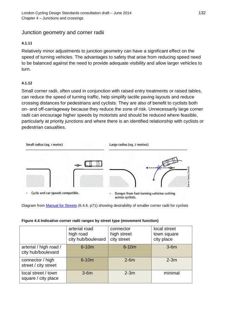
London Cycling Design Standards consultation draft – June 2014 132
Chapter 4 – Junctions and crossings
Junction geometry and corner radii
4.1.11
Relatively minor adjustments to junction geometry can have a significant effect on the
speed of turning vehicles. The advantages to safety that arise from reducing speed need
to be balanced against the need to provide adequate visibility and allow larger vehicles to
turn.
4.1.12
Small corner radii, often used in conjunction with raised entry treatments or raised tables,
can reduce the speed of turning traffic, help simplify tactile paving layouts and reduce
crossing distances for pedestrians and cyclists. They are also of benefit to cyclists both
on- and off-carriageway because they reduce the zone of risk. Unnecessarily large corner
radii can encourage higher speeds by motorists and should be reduced where feasible,
particularly at priority junctions and where there is an identified relationship with cyclists or
pedestrian casualties.
Diagram from Manual for Streets (6.4.6, p71) showing desirability of smaller corner radii for cyclists
Figure 4.4 Indicative corner radii ranges by street type (movement function)
arterial road high road city hub/boulevard
connector high street city street
local street town square city place
arterial / high road / city hub/boulevard
6-10m 6-10m 3-6m
connector / high street / city street
6-10m 2-6m 2-3m
local street / town square / city place
3-6m 2-3m minimal

London Cycling Design Standards consultation draft – June 2014 133
Chapter 4 – Junctions and crossings
4.1.13
Many existing streets operate in a satisfactory way with minimal corner radii, even a kerb
quadrant only. Designers should start from the assumption that corner radii should be
minimised to benefit vulnerable road users, and then test whether this raises any issues.
Figure 4.4 shows, indicatively, how corner radii might vary according to the two types of
street meeting at a junction, based on the movement function of the street type. For types
with a higher place function, the lower end of the range should be used.
4.1.14
Street types are not the only site-specific factor to take into account when making
decisions about corner radii. Other variables that may justify selecting radii towards the
lower end of the ranges in figure 4.4 include:
lower speeds (ideally with a 20mph limit), either on the individual streets or on an
area-wide basis
few large vehicles needing to turn
wider carriageways and lanes
more than one lane (turning vehicles may straddle lanes to turn where there is more
than one)
central islands and ASLs
uphill or level gradients (on the basis that rear-end shunts could be an issue
downhill where turning vehicles may decelerate abruptly to turn)
4.1.15
As part of the design process, swept path
analysis should be used to track the paths of
larger vehicles around corners. (Manual for
Streets, 6.3.13) It is usually acceptable for large
vehicles to enter the opposing general traffic
lane or adjacent with-flow lane in order to turn,
provided there are no physical constraints to
them doing so. There may need to be some
local strengthening of the footway to allow for
larger vehicles occasionally overrunning the
corner, and it may be necessary to move back a
pedestrian crossing, stop line or ASL in order to
accommodate turning movements.
Swept path analysis
4.1.16
It is important not to design geometry solely based on infrequent use by large vehicles,
such as refuse or removal trucks but, in all instances, the designer needs to take account
of the individual site characteristics when choosing the appropriate corner radii. Provided

London Cycling Design Standards consultation draft – June 2014 134
Chapter 4 – Junctions and crossings
drivers can make the turn within the overall road space available, it is rarely necessary to
design so that they can do so while remaining in a single nearside lane.
4.1.17
In most circumstances, the safety benefits to cyclists of tighter geometry and the slowing
of motorised vehicle turning movements outweigh risks to cyclists that exist in relation to
larger vehicles moving out to the centre of the carriageway to make a left turn. Turning
vehicles should, according to Highway Code rule 183, give way to a nearside cycle lane,
while cyclists should not seek to undertake at priority junctions where any possibility exists
that a vehicle may be turning left.
4.1.18
Any change to junction geometry should
also take into account the impact on
sight-lines, which are needed to ensure
adequate visibility at junctions.
Conformity with Manual for Streets
guidance is recommended:
for side roads, the minimum 2.4m
‘X’ distance should be used –
allowing full visibility for the driver
of an emerging vehicle without
needing to cross the give way
markings
Diagram from Manual for Streets showing x- and y-
distances are defined.
in low flow situations, 2.0m may be acceptable, although it is likely to require some
protrusion into the main carriageway.
for cycle tracks crossing other routes or footpaths, the minimum ‘Y’ distance should
be 20m (based on a cycling speed of 12mph)
4.1.19
Reducing visibility should not compromise cycle safety at priority junctions and a risk
assessment should be undertaken to check whether reduced ‘Y’ distances and tighter
geometry generally are acceptable from a cycling perspective. There may, for example, be
occasions where horizontal deviations to improve cyclists’ sight lines or speed humps
should be added on the approach to a crossing, junction or shared-use area.
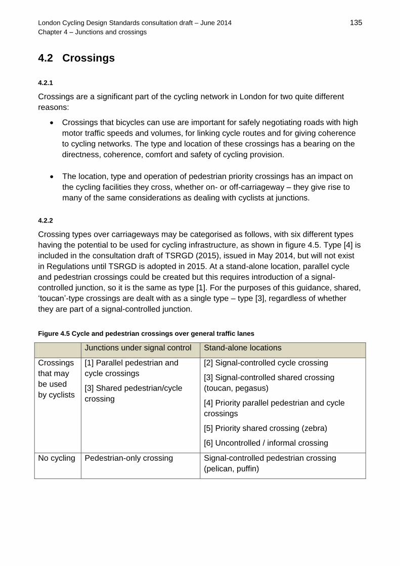
London Cycling Design Standards consultation draft – June 2014 135
Chapter 4 – Junctions and crossings
4.2 Crossings
4.2.1
Crossings are a significant part of the cycling network in London for two quite different
reasons:
Crossings that bicycles can use are important for safely negotiating roads with high
motor traffic speeds and volumes, for linking cycle routes and for giving coherence
to cycling networks. The type and location of these crossings has a bearing on the
directness, coherence, comfort and safety of cycling provision.
The location, type and operation of pedestrian priority crossings has an impact on
the cycling facilities they cross, whether on- or off-carriageway – they give rise to
many of the same considerations as dealing with cyclists at junctions.
4.2.2
Crossing types over carriageways may be categorised as follows, with six different types
having the potential to be used for cycling infrastructure, as shown in figure 4.5. Type [4] is
included in the consultation draft of TSRGD (2015), issued in May 2014, but will not exist
in Regulations until TSRGD is adopted in 2015. At a stand-alone location, parallel cycle
and pedestrian crossings could be created but this requires introduction of a signal-
controlled junction, so it is the same as type [1]. For the purposes of this guidance, shared,
‘toucan’-type crossings are dealt with as a single type – type [3], regardless of whether
they are part of a signal-controlled junction.
Figure 4.5 Cycle and pedestrian crossings over general traffic lanes
Junctions under signal control Stand-alone locations
Crossings
that may
be used
by cyclists
[1] Parallel pedestrian and
cycle crossings
[3] Shared pedestrian/cycle
crossing
[2] Signal-controlled cycle crossing
[3] Signal-controlled shared crossing
(toucan, pegasus)
[4] Priority parallel pedestrian and cycle
crossings
[5] Priority shared crossing (zebra)
[6] Uncontrolled / informal crossing
No cycling Pedestrian-only crossing Signal-controlled pedestrian crossing
(pelican, puffin)

London Cycling Design Standards consultation draft – June 2014 136
Chapter 4 – Junctions and crossings
4.2.3
The regulatory framework on crossings is described in the Zebra, Pelican and Puffin
Pedestrian Crossings Regulations and General Directions (1997) until this is superseded
by the revised TSRGD in 2015. Advice and guidance is provided by DfT in LTN1/95,
Assessment of Pedestrian Crossings, LTN 2/95, Design of Pedestrian Crossings, TAL5/05
Pedestrian facilities at signal-controlled junctions (2005) and Signing The Way (2011).
4.2.4
Reference should also be made to Guidance on the use of tactile paving surfaces, which
describes requirements for accessible crossings. All crossings should be step-free, which
can be achieved either through dropped kerbs or by placing crossings on a raised table or
entry treatment. There may also be advantages for partially sighted people in using a
surface material for the crossing that has a colour contrast with the carriageway. Relevant
streetscape and local design guidance should be consulted for advice about materials.
Crossing on a raised table and with contrasting
surface treatment, Waterden Road, Hackney
Wide crossing, consisting of two parallel stand-alone,
signal-controlled crossings, with contrasting surface
treatment, St Paul’s Churchyard, City of London
Selecting the crossing type
4.2.5
For a cycle route crossing a road, the most appropriate crossing choice generally depends
on the traffic conditions of the road in question – indicative flows by crossing type are
shown in figure 4.6. Since signals are expensive to install, operate and maintain and tend
to have a negative impact on the street environment, signalisation should be a last resort.
For that reason, types [4] to [6] are generally recommended for the lower-intervention
Quietways, although new signals may be needed in some locations. Use of zebras and
uncontrolled crossings is unlikely to be adequate for high-capacity Superhighways.
4.2.6
At a site-specific level, the appropriate crossing option for a given location also depends
on the character of the place in question and considerations of street clutter and
accessibility. Where a pedestrian or cycle desire line has been identified, type [6], an

London Cycling Design Standards consultation draft – June 2014 137
Chapter 4 – Junctions and crossings
uncontrolled crossing, should be considered first, as the ‘lowest intervention’ form. This is
likely to be suitable for locations with relatively low levels of use by those crossing and
where traffic speeds and volumes are low enough to allow safe opportunities for crossing.
Figure 4.6 Cycle crossing options
Type of crossing Flows (24hr)
All vehicles
(carriageway)
Bicycles
(crossing)
Pedestrians
(crossing)
SU
PE
RH
IGH
WA
YS
1. Parallel signal-controlled
pedestrian & cycle crossing
> 8,000 Medium-
High
Medium-
High
2. Signal-controlled cycle-only
crossing
> 8,000 Medium-
High
None
Q
UIE
TW
AY
S
3. Shared pedestrian/cycle crossing
(Toucan / Pegasus)
> 8,000 Low-
Medium
Low-
Medium
4. Parallel priority pedestrian/cycle
priority crossing 3,000-8,000 Medium
Low-
Medium
5. Shared pedestrian/cycle priority
crossing (Zebra)
3,000-8,000 Low to
Medium
Medium
6. Uncontrolled (central refuge) 3,000-8,000 Low Low
Crossings at signal-controlled junctions
4.2.7
Cycle tracks or shared use paths/areas may be joined across one arm of a junction under
signal control by using either a shared or separate, parallel pedestrian and crossings or by
using type [3], a shared crossing. Parallel crossings, type [1], are a good option where
there is high demand by both cyclists and pedestrians, thus reducing potential conflicts
between the two modes on the crossing. They may be particularly useful where cyclists
are approaching from a different direction from pedestrians. This is often the case when
one route is a side street closed to motor traffic. Type [2] is a variant where there is no
parallel pedestrian crossing facility. For this type, reliable cycle detection, or a push-button,
should be used so that demand can be prioritised and delay minimised. Where the cycle
crossing cannot align with the cycle route in a way that allows cyclists to remain on
carriageway, a shared use area will be required to allow access to the crossing.

London Cycling Design Standards consultation draft – June 2014 138
Chapter 4 – Junctions and crossings
Type [1]: parallel crossings at Westferry and West India Dock Road.
Ladder and tramline tactile paving are used for transition from track to
shared area.
Type [2]: stand-alone cycle
crossing at Goswell Road
4.2.8
Square elephant’s footprints markings are recommended for both type [1] and [2]
crossings, although pedestrian crossing studs are also sometimes used for this purpose.
The consultation draft of TSRGD (2015) proposes a general authorisation for elephants’
footprints to mark a parallel cycle route at a crossing under signal control, where
previously site-specific authorisation was required. This should add consistency and will
bring the UK into line with other parts of Europe on use of a square-format marking for
cycle crossings.
Signal-controlled cycle crossings, using elephant’s footprint markings through the junction
4.2.9
In some cases, providing cycle gaps through islands may more be appropriate than
marking elephant’s footprints across the carriageway. It may be necessary to use ‘Keep
Clear’ markings so that queuing traffic on the carriageway does not block the crossing.

London Cycling Design Standards consultation draft – June 2014 139
Chapter 4 – Junctions and crossings
Cycle gaps – in the example on the right, the crossing area is created by using ‘Keep Clear’ markings
Stand-alone signal-controlled crossing
4.2.10
Shared crossings at stand-alone signals are
known either as toucan or pegasus crossings, the
latter being a special type that also allows horse-
riders to cross. As part of signal-controlled
junctions, they are generally not known by these
names but the design issues are similar. In a
toucan crossing, the surface of the crossing and
footway areas immediately on either side are
shared, although there may be some separation
up to that point.
Pegasus crossing
Variants to the standard toucan layout are possible for locations such as side-road
junctions that can enable more direct crossings. The DfT provides guidance in TAL 10/93,
Toucan: an unsegregated crossing for pedestrians and cyclists and in TAL 4/98, Toucan
crossing development.
Typical toucan crossing arrangements, with shared use and tracks on either side (colour optional)

London Cycling Design Standards consultation draft – June 2014 140
Chapter 4 – Junctions and crossings
Toucan crossings are often used to carry off-
carriageway tracks through or around junctions
Toucan crossing used to connect streets for cyclists
across a main road, Featherstone Street/Leonard
Street
Parallel priority crossings
4.2.12
The consultation draft of the revised TSRGD (2015)
proposes a new crossing type that would allow for
parallel pedestrian and cycle crossings without the need
to install signal controls. This priority crossing is similar
in appearance to a zebra crossing but with a parallel
route for cyclists, marked with elephants’ footprints
within the controlled area of the crossing. This type will
be available to use when the new regulations are
adopted in 2015 and will bring the UK more into line
with international best practice. Details are yet to be
established, including whether two sets of elephants’
footprints markings are possible on one crossing and
whether diagram 1057 cycle symbols may be used on
the crossing area.
Draft revised TSRGD,
table 69, item 51
The case for parallel priority crossings. In the UK (left), regulations have not previously allowed for a parallel
cycle route at a priority crossing – cyclists are asked to give way twice. A much simpler approach exists in
Stockholm, right, where cycle crossings with elephants’ footprints are provided within the controlled area of
the ‘zebra-type’ priority crossing.

London Cycling Design Standards consultation draft – June 2014 141
Chapter 4 – Junctions and crossings
Indicative layout 4/01: Parallel crossing transfers cycle track to the opposite side of a carriageway
4.2.13
The parallel priority crossing could be used to connect off-carriageway tracks across a
main road, to allow crossing from and to streets closed to motorised traffic and to shift two-
way cycle tracks from one side of the road to the other.
Priority (zebra) crossing
4.2.14
Wherever possible, separate parallel crossings should be provided for pedestrians and
cyclists. However, a low-intervention option may be to use a zebra crossing to take a cycle
route over a main road. This option is likely to work best where there are low flows of both
pedestrians and cyclists, and could be a pragmatic choice where there are existing shared
use footways on either side of the carriageway – for example, in a ‘high road’ location near
a school.
Conventional zebra crossing (left), with buff blister tactiles. Shared area on either side of the zebra (right) to
legitimise cycle use of the crossing.

London Cycling Design Standards consultation draft – June 2014 142
Chapter 4 – Junctions and crossings
4.2.15
DfT's Signing The Way (2011) invited highway authorities to permit, at trial locations, cycle
use of zebra crossings where they join off-carriageway cycle routes. TfL's position,
drawing on conclusions from TRL's Shared Zebra Crossing Study (2006), is that cyclists
can legally ride across zebra crossings in this scenario. A risk assessment of any proposal
for cyclists to use zebras is important: although it is not illegal for cyclists to ride over zebra
crossings in these instances, they do not formally have the same priority as pedestrians
over traffic using the carriageway.
4.2.16
Special design considerations for priority crossings that cyclists may use include: geometry
designed to accommodate both pedestrian and cycle flows; design to force cyclists to slow
or stop and to give them adequate visibility before crossing; and signing and road marking
to make other users aware of the likely presence of cyclists on the crossing.
4.2.17
Where a zebra crossing is marked across a street with a cycle lane, the lane markings
may not be continued through the zig-zag markings that show the controlled area of the
crossing. However, the consultation draft of TSRGD (2014) allows for the zig-zags to be
moved away from the kerbside to align with the cycle lane markings and allow for greater
visual continuity of the cycle facility.
Indicative layout 4/02: Continuity of cycle lane at priority crossing
4.2.18
Note that the number of zig-zag markings may be reduced to from eight to two, depending
on site-specific conditions such as visibility and the existence of other parking controls.
Where the number of zig-zags is reduced, it may be advisable to widen the crossing,
especially where the approach is not straight.
For carriageway widths of 6m or less, the central set of zig-zags may be omitted.

London Cycling Design Standards consultation draft – June 2014 143
Chapter 4 – Junctions and crossings
Indicative layout 4/03: Two zig-zag markings at zebra crossing
Uncontrolled crossings
4.2.19
Uncontrolled crossing points for pedestrians and cyclists generally consist of dropped
kerbs on either side of the carriageway, with an 800m strip of blister tactile paving across
the width of the crossing area, to the dropped kerb. A 2m-deep central island to provide
protected waiting space can be beneficial along with road narrowing, provided this does
not create pinch points for cyclists using the carriageway. Some speed reduction
measures on the carriageway may also be appropriate.
Uncontrolled crossing, Sidmouth Street, Camden
Dropped kerbs for uncontrolled crossing,
College Street, City of London
4.2.20
These ‘courtesy’ crossings do not give priority over vehicles on the carriageway. However,
introduction of give-way signs and markings for motorists with a raised table would give
formal priority to crossing pedestrians or cyclists without the need for a zebra crossing.

London Cycling Design Standards consultation draft – June 2014 144
Chapter 4 – Junctions and crossings
4.2.21
A variant of the uncontrolled crossing is to use materials and streetscape features to
‘suggest’ that a crossing facility exists, encouraging drivers to slow down through the
space and give way as necessary to anyone wanting to cross. These facilities can include
informal crossing areas that are striped in the manner of a zebra crossing but do not
otherwise meet regulatory requirements (therefore they do not confer any formal priority
on the crosser). These kinds of approaches are often used in shared space schemes.
‘Suggested’ crossing places in high street environments in Bexleyheath (left) and Hornchurch (right), using
streetscape features such as raised tables, median strips, planting and a distinctive palette of materials to
help break down dominance of the environment by motorised vehicles.
Pedestrian crossing of cycle tracks
4.2.22
For segregated lanes/tracks and light segregated lanes, crossings should ideally extend
from footway to footway. In that way, the cycling facility is included within the controlled
area of the crossing. This also avoids the need to design a separate way for pedestrians to
cross a cycle track.
Signalised and priority (zebra) crossings extending over both carriageway and cycle track
4.2.23
Where there is not a crossing facility that can extend across both carriageway and
segregated cycle lane/track, then uncontrolled and suggested crossings are likely to be

London Cycling Design Standards consultation draft – June 2014 145
Chapter 4 – Junctions and crossings
the most practical options, given that signalisation or installing a fully compliant zebra
crossing would be too heavy handed and expensive for a short crossing only involving
cyclists and pedestrians. Many other countries have a small, uncomplicated crossing type
that gives crossing pedestrians priority over the cycle track.
4.2.24
In some instances, it may be appropriate to use an uncontrolled crossing to allow
pedestrians to cross a cycle track next to the carriageway to an island and then a zebra or
pelican crossing over the main part of the carriageway. In this case, the crossings should
be staggered so it is clear that the two sections have a different status.
‘Mini zebra crossing’ over a cycle track, Stockholm
Pedestrian crossing over a cycle track
in Seville, with extra warning for cyclists

London Cycling Design Standards consultation draft – June 2014 146
Chapter 4 – Junctions and crossings
4.3 Priority junctions
4.3.1
The majority of highway junctions are of the ‘priority’ type – crossroads and T-junctions –
where vehicle priority is given to traffic on the major road. The priority is usually indicated
by give-way or stop-lines and associated signs, or suggested by pedestrian refuges and
traffic islands. In some cases no road markings may be considered to be necessary where
vehicle speeds and flows are low.
Figure 4.7 Summary of options for cycle-friendly interventions at priority junctions
QU
IET
WA
YS
1. Introduce
refuge island(s)
Recommended to support cycle and pedestrian crossing,
and cycle right turns, but only where avoiding the creation
of pinch-points with unacceptable widths.
SU
PE
RH
IGH
WA
YS
2. Reduce speed
on turning (entry
treatments and
raised tables)
Speed reduction generally is beneficial (see chapter 5). On
cycle routes, selective use of entry treatments and raised
tables can address common risks on turning and suggest
visual priority for cyclists and pedestrians. Other changes
to geometry that can support speed reduction include: kerb
realignment, reduced corner radii, reduced width of junction
mouth and footway build-outs. Preventing or restricting
parking and loading close to the junction is an important
supporting measure in most cases, helping to maintain
good visibility.
3. Road markings
through junction
Visual priority can be supported by a combination of: use of
TSRGD diagram 1057 cycle symbols, dashed diagram
1010 markings across the mouth of the junction and
coloured surfacing. These interventions raise road user
awareness of the presence and legitimacy of cycling and
specific cycle movements.
4. Introduce new
crossing
Crossings on a main road can help cycle movements in
and out of a side road. For streets with a higher movement
function, consideration could be given to allowing cycle left
and right turns by diverting cyclists onto shared areas of
footway and parallel or toucan crossings. See section 4.2.
5. Change or
reverse priority /
Ban specific
movements
These changes can help address specific conflicts between
turning motorised vehicles and cyclists and enhance the
directness, safety and comfort of a cycle route.
Interventions such as these need to be part of a wider
traffic management approach.
6. Convert to
signalised junction
A last resort, justification for which would need to be made
on multiple grounds, according to TfL’s Design standards
for signal schemes, SQA064 (2014). See section 4.4.

London Cycling Design Standards consultation draft – June 2014 147
Chapter 4 – Junctions and crossings
4.3.2
For cyclists, key issues relate to the safety and comfort of moving ahead through a priority
junction while motorised traffic seeks to turn in or out, and the safety, comfort and
directness of cycle turns into and out of junctions. Priority for ahead cyclists is covered in
section 3.5. Any turn for cyclists that involves moving across more than one lane of
motorised traffic in one step is likely to be uncomfortable for most users. This section
focuses on methods of addressing this issue – its scope is summarised in figure 4.7.
Refuge islands
4.3.3
For cycling infrastructure, two separate issues need to be considered with the use of
refuge islands:
where islands are provided to assist pedestrians crossing the road or for driver
guidance, they must avoid creating pinch-points for cyclists; and
the potential for assisting cyclists by allowing them to make difficult turns under the
‘shadow’ of a protecting island.
Indicative layout 4/04: Cycle lanes at pedestrian refuge island / uncontrolled crossing
4.3.4
Guidance on widths in figure 4.8 should be followed so as to avoid intimidating close
passes of cyclists by motorised vehicles at refuge islands. Driver awareness can be
increased by continuing a cycle lane through the area (which usually requires conversion
from mandatory to advisory in order to allow for some possible encroachment by
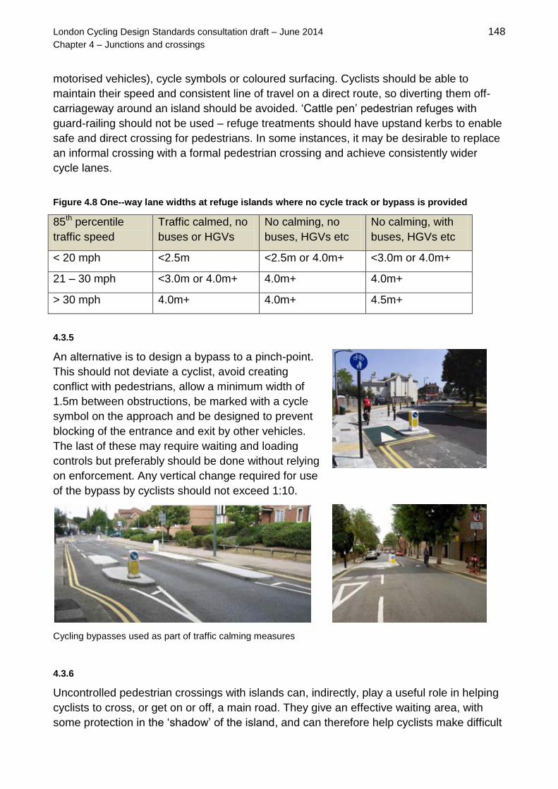
London Cycling Design Standards consultation draft – June 2014 148
Chapter 4 – Junctions and crossings
motorised vehicles), cycle symbols or coloured surfacing. Cyclists should be able to
maintain their speed and consistent line of travel on a direct route, so diverting them off-
carriageway around an island should be avoided. ‘Cattle pen’ pedestrian refuges with
guard-railing should not be used – refuge treatments should have upstand kerbs to enable
safe and direct crossing for pedestrians. In some instances, it may be desirable to replace
an informal crossing with a formal pedestrian crossing and achieve consistently wider
cycle lanes.
Figure 4.8 One--way lane widths at refuge islands where no cycle track or bypass is provided
85th percentile
traffic speed
Traffic calmed, no
buses or HGVs
No calming, no
buses, HGVs etc
No calming, with
buses, HGVs etc
< 20 mph <2.5m <2.5m or 4.0m+ <3.0m or 4.0m+
21 – 30 mph <3.0m or 4.0m+ 4.0m+ 4.0m+
> 30 mph 4.0m+ 4.0m+ 4.5m+
4.3.5
An alternative is to design a bypass to a pinch-point.
This should not deviate a cyclist, avoid creating
conflict with pedestrians, allow a minimum width of
1.5m between obstructions, be marked with a cycle
symbol on the approach and be designed to prevent
blocking of the entrance and exit by other vehicles.
The last of these may require waiting and loading
controls but preferably should be done without relying
on enforcement. Any vertical change required for use
of the bypass by cyclists should not exceed 1:10.
Cycling bypasses used as part of traffic calming measures
4.3.6
Uncontrolled pedestrian crossings with islands can, indirectly, play a useful role in helping
cyclists to cross, or get on or off, a main road. They give an effective waiting area, with
some protection in the ‘shadow’ of the island, and can therefore help cyclists make difficult

London Cycling Design Standards consultation draft – June 2014 149
Chapter 4 – Junctions and crossings
or uncomfortable manoeuvres in more than one step. This can be particularly useful where
a (minor) cycle route crosses a busier road. Islands either side of a priority junction can
provide a even more protected space to make two-stage cycle movements. This
arrangement may require banning of right turns by motorised vehicles.
Pedestrian refuge island assists cycle
right turn
Illustrative layout 4/05: Island-protected cycle right-turn into side road
4.3.7
Islands may be useful for protecting cyclists in other circumstances, such as the continuity
and safety of contraflow cycling facilities run through a priority junction, or protecting cycle
lanes from motor vehicle incursion just before priority junctions.
Island protecting contraflow cyclists at priority
junction, Paul Street, Hackney
Hatched area and island protection before side
road access, Baylis Road, Lambeth

London Cycling Design Standards consultation draft – June 2014 150
Chapter 4 – Junctions and crossings
Entry treatments, raised tables and footway build-outs
4.3.8
Research has shown that side-road entry-treatments have significant safety benefits for
cyclists, particularly where provided in conjunction with other street enhancements, such
as tree planting. A reduction of around 30 per cent in cycle collisions was found at over
1,000 sites in London. (TfL, Effect of Side Raised Entry Treatments on Road Safety in
London - London Road Safety Unit Research Summary No 9, 2007.) Entry treatments to
side roads adjacent to a main road are therefore recommended for a cycle route on the
main road. However, all vertical forms of traffic calming, even well designed examples, add
some discomfort for cyclists riding over them. They may therefore be appropriate on other
roads that are traversed by a cycle route or have cycle usage, but a balanced view needs
to be taken of the benefits they offer relative to the downsides.
Entry treatment with asphalt table, Gray’s Inn
Road / Heathcote Street, Camden
Block-paved entry treatment with tight corner
radii – Walworth Road, Southwark
Typical entry treatments in the City of London, with visual contrast with carriageway: at a narrow street with
cycle contraflow (Cloak Lane, left) and at a two-way street (Trump Street, right)
4.3.9
To provide the best conditions for cyclists, and to encourage motorists to make careful
turning movements into and out of side roads, entry treatments should:
narrow the side-road carriageway to between 5.0m and 6.5m, depending on the
type of traffic using the road (greater widths are likely be required on access routes
used by buses, emergency response vehicles, HGVs and refuse collection trucks)
use a corner radius of kerb-line below 6.0m – see section 4.1 for further guidance

London Cycling Design Standards consultation draft – June 2014 151
Chapter 4 – Junctions and crossings
raise the carriageway by 50-100mm, up to the same level as the adjacent footway
use materials that have a visual contrast with the carriageway surface to raise
awareness (bearing in mind guidance in chapter 7 of this document and in other
streetscape and local design guides on appropriate surface materials, particularly
from a maintenance perspective)
use approach sinusoidal ramps, with 1:10 gradient (shallower gradients may be
needed on bus and emergency-service routes)
be constructed using asphalt ramps or other non-skid material
provide flat pedestrian crossing areas of at least 3m width with blister tactile-paving
(off carriage/cycleway) to indicate crossing location
avoid upstands of more than 6mm where pedestrians cross (as this is likely to
interfere with the movement of people in wheelchairs)
provide cycle stands on footway space created by the entry treatment where
demand for them is reasonably anticipated – allowing for considerations of visibility,
these and other forms of street furniture can fulfil a similar function to bollards to
prevent vehicle over-run of the footway area.
Illustrative layout 4/06: Raised entry treatment
Ramp up to entry treatment, Gresham Street,
City of London
4.3.10
Raised tables extend the logic of raised entry treatments
across all arms of a junction or crossing area, which can
be effective in slowing turning movements but, again,
puts in place a vertical shift for cyclists moving through a
junction. Where assessment of the junction indicates
that there would be a net benefit from a safety and
comfort perspective in constructing a raised junction
table, these are recommended cycle routes, provided
they are constructed in accordance with the above
advice. Like entry treatments, junction tables convey to
motorists not to expect to have priority over other road
users, and to turn with appropriate caution.
Raised table, Mercer Street,
Westminster

London Cycling Design Standards consultation draft – June 2014 152
Chapter 4 – Junctions and crossings
4.3.11
Entry treatments and raised tables do not require Traffic Orders but are covered by the
Highways (Road Humps) Regulations 1999. These state that the highest point on a flat-
topped road hump must be within 25 and 100mm of the carriageway surface. In order to
construct a raised entry treatment flush with the footway on either side where kerb heights
are greater than 100mm, some raising of the carriageway surface in the area leading up to
the entry treatment will be necessary to meet the 100mm requirement.
4.3.12
It may be beneficial to continue footway and cycleway treatments across the mouth of the
side road to convey further necessary priority for pedestrians and cyclists. Turning
vehicles will need to negotiate a change in level, and they must enter and pass through a
zone that looks and feels different and where they should clearly cede priority to other
users. This is not practised often in the UK but has been applied in key cycling routes in
cities such as Copenhagen and Stockholm.
Continuous footway treatments in Stockholm
Continuous footways in Copenhagen – with footway materials continued through (left) and varied (right)

London Cycling Design Standards consultation draft – June 2014 153
Chapter 4 – Junctions and crossings
4.3.13
An alternative method employed in Copenhagen is to run a stepped cycle track with a
continuous treatment past a side road and continue the footway through but in a different
material from the rest of footway. In the UK, a treatment of this kind could be a good
method of demonstrating to pedestrians that they have reached a side road, without
requiring addition of tactile paving.
Illustrative layout 4/07: Continuous footway treatment
Continuous footways in Lambeth – Coldharbour Lane, Clapham Old Town

London Cycling Design Standards consultation draft – June 2014 154
Chapter 4 – Junctions and crossings
4.3.14
Footway build-outs at priority junctions may be used in conjunction with side-road entry
treatments to enhance some of the vehicle-slowing aspects of the design and also create
either additional footway space or an opportunity for tree planting and greening of the
street. Build-outs provide pedestrians with shorter crossing widths and additional visibility
when crossing the road at junctions and island sites. However, it is essential from both a
road safety and movement perspective that build-outs do not cause pinch-points, forcing
cyclists to deviate into the path of vehicles, or restricting cycle flows.
4.3.15
For any proposed build-out, remaining one-
way widths should be consistent with the
guidance on pinch-points provided in figure
4.7 – namely that, in most instances at least
4.0m one-way width will need to remain
after the build-out on most street types,
even if there are no large vehicles turning.
For local streets and others in 20mph
zones, there can be more flexibility and
build-outs can be used that reduce the
remaining (two-way) carriageway width to
5.5-6.0m.
Footway build-out incorporating cycle parking
Road markings through junctions
4.3.16
As shown in the illustrative layouts throughout this section, marking cycle lanes through
priority junctions in the direction of the cycle route is recommended as a method of
increasing subjective safety with regard to the potential of other vehicles turning across
cyclists. The lane markings raise the awareness of drivers of the likely presence of cyclists
in a nearside lane and help give visual continuity to a cycling facility.
Dashed lane markings continued past side roads with and without entry treatments.

London Cycling Design Standards consultation draft – June 2014 155
Chapter 4 – Junctions and crossings
4.3.17
As presented in the consultation draft of TSRGD (2015), the diagram 1010 marking, a
shorter dash than the advisory cycle lane marking (1000mm rather than 4000mm), should
be used for lanes through junctions in order to give a visual indication to all road users of a
change in hazard associated with the junction. Until the revised TSRGD comes into
operation, DfT has authorised for TfL the a short-dash ‘variant 1010’ marking (850mm
wide with an 1150mm gap rather than a 1000mm dash and 1000mm gap) for this purpose
and could do the same for other highway authorities. See section 6.3 for further details.
4.3.18
DfT’s Signing the Way (2011) cites qualitative research with cyclists to support the
desirability of using lane markings through junctions from a cycle safety perspective.
(AECOM, Traffic Signs Policy Review: Research Project into the Awareness of the
Meaning of Traffic Signs Project PPRO 04/16/24, 2011) The TRL report for DfT
Infrastructure and Cyclist Safety (PPR 580, 2011) is also supportive of cycle lanes
continued through junctions.
4.3.19
On streets without cycle lanes, then TSRGD diagram 1057 cycle symbols may be used
across junctions and accesses. These are usually positioned at the points where a cyclist
should enter and exit from the side road and, in that way, help to guide appropriate cyclist
positioning as well as alerting other road users to the presence of cyclists. They remove
any need for other warning signs to diagrams 962.1 or 963.1 except for situations where
contra-flow cycling is permitted. At side roads with restricted access or less than 5m wide,
kerb-to-kerb, one rather than two diagram 1057 markings may be used. On Cycle
Superhighways, the CS project symbols (diagram 1057 marking with route number on a
coloured patch) may be used to mark continuity of a cycle facility through a priority
junction. See section 6.3 for further details on use of road markings for these purposes.
4.3.20
In all instances, analysis of cyclist
movements through the junction should be
undertaken prior to any decision about
placement of lane markings or symbols.
Care should be taken not to direct cyclists
into taking inappropriate riding positions
through the junction. Where there is
insufficient space through a junction for a
large vehicle to overtake a cyclist, for
example, a marked lane should not be
provided as cyclists should be discouraged
from adopting a secondary riding position.
TSRGD diagram 1057 symbols positioned so as to
mark a cycle route through a junction

London Cycling Design Standards consultation draft – June 2014 156
Chapter 4 – Junctions and crossings
4.4 Signal-controlled junctions
4.4.1
Various improvements to cycle safety and comfort, and to the directness and coherence of
cycle routes may be achieved through remodelling or introducing signal control at
junctions, particularly where signal timings can be changed to reallocate time between
road users and generate time saving benefits for cyclists. Intervention types covered in
this section are summarised in figure 4.9.
Figure 4.9 Summary of options for cycle-friendly interventions at signal-controlled junctions
SU
PE
RH
IGH
WA
YS
1. Separate signals
for cyclists
Complete separation at junctions involves signalling
cyclists separately to remove all conflicting movements
with other users.
2. Managing or
removing conflict
with left-turning
vehicles
This may be done by separately signalling left-turners
(removing the conflict) or seeking to move the point of
conflict away from the junction itself (managing the
conflict), usually through lane markings.
QU
IET
WA
YS
3. Support for cycle
right turn
As part of a segregated cycling system or a wider strategy
on a route or a series of junctions to keep cyclists in a
predictable position on the nearside, cyclists could be
assisted with right turns by staying on the nearside and
making the turn in two stages.
4. Cycle bypass of
signals
In some instances, particularly through signalised T-
junctions, cyclists making certain movements may be
permitted a bypass of the signal control.
5. Using ASLs and
feeder lanes
ASLs can help cyclists take a safer, more advantageous
position at a signal-controlled junction during certain
signal phases and so, selectively, can assist cycle
movements through a junction.
6. Banning selected
motorised vehicle
movements
Generally in conjunction with other measures listed here,
certain vehicle movements could be banned to improve
cycle safety and directness. This should be done as part
of a wider traffic management approach rather than on a
case-by-case basis.
7. Convert to a
priority junction
Signal removal can have some beneficial effects where
the volume and mix of traffic and nature of conflicting
movements does not necessarily justify the existence of a
signal-controlled junction. See section 4.3.
8. Remove all
priority and
declutter
As part of an integrated, area-wide approach, designers
may explore the potential benefits of removing signal
control and priority altogether in order to promote more
consensual road user behaviour generally. See chapter 3
on cycle-friendly street design.

London Cycling Design Standards consultation draft – June 2014 157
Chapter 4 – Junctions and crossings
4.4.2
Introducing new signal control or major re-engineering of existing signal-controlled
junctions should be considered primarily as a tool for application to high-capacity
Superhighways, on streets with a higher movement function. On Quietways, new or
substantially changed traffic signals are less likely to feature, with greater emphasis on
simplification of layouts and decluttering. TfL’s Design standards for signal schemes,
SQA064 (2014) should be consulted for guidance on procedures involving traffic signals.
4.4.3
The primary purpose of traffic control by light signals is to separate conflicting traffic by the
division of time, within the available road space, in a safe, efficient and equitable manner.
(Traffic Advisory Leaflet 1/06, General principles of traffic control by light signals, 2006,
Part 1) Detection technology is widely used to optimise the operation of traffic signals. This
allows for sequence flexibility if no users are detected and for green signal optimisation
during busy periods.
4.4.4
Benefits arising from being able to control movements of road users at traffic signals need
to be weighed up against the potential disadvantages to cyclists. Minimising delay is a
primary objective in achieving a level of service that attracts new cyclists: few advantages
are to be gained from signals for cyclists that require them to wait a long time at signals.
Delays to cyclists of over 120 seconds due to signals are to be avoided.
4.4.5
Decluttering by minimising use of, or removing, traffic signals is positive for more attractive
streets. Although it offers some adaptability through the ability to manage signal timings,
junction remodelling with substantial changes to traffic signal infrastructure, may also
place limits on the growth of cycling on a given route and necessitate further re-
engineering in the near future.
Care should be taken to avoid introducing signal control where it is not justified. This can
result in increased journey times for all users and is costly to install and maintain. Over-
complicated signal staging and operation can lead to excessive waiting times for cyclists
and an increase in non-compliance.
4.4.6
In seeking to improve cycle safety, comfort and directness at junctions, the timing of
signals should generally be reviewed and optimised to minimise delay for cyclists, taking
account of the needs of all traffic and of pedestrians. When calculating inter-green timings
allowance must be made for cycle movements to ensure cyclists can safely clear the
junction. This is particularly important where cycle speeds are likely to be lower due to
gradients.

London Cycling Design Standards consultation draft – June 2014 158
Chapter 4 – Junctions and crossings
Procedures for traffic signals
4.4.7
TfL Traffic Infrastructure, within the Asset Management Directorate, is the Signals
Authority for London, responsible for the design, installation, commissioning, maintenance
and decommissioning of traffic signals and associated equipment. TfL Network
Performance, within the Road Space Management Directorate, is responsible for the
management and operation of London’s traffic signals and their accompanying systems,
technologies and equipment.
4.4.8
The Traffic Management Act 2004 places a Network Management Duty on all local traffic
authorities (LTAs) in England. The Duty requires the LTA to ‘ensure the expeditious
movement of traffic on its own road network, and facilitate the expeditious movement of
traffic on the networks of others’. ‘Expeditious movement’ and ‘congestion’ are subjective
terms. TfL Network Performance therefore uses journey time reliability as a more practical
measure to help clarify the legal responsibility. Modelling is the tool used to measure
scheme impact on the network and effects on journey time reliability. The way this is
applied across London is described in the Traffic modelling guidelines (version 3), issued
in September 2010.
4.4.9
For any scheme involving traffic signals, authorities are required to comply with
procedures set out in Design standards for signal schemes, SQA064 (2014) and any
subsequent document updates.
4.4.10
Criteria in SQA064 are based on the collision rate at the junction, and on flows of traffic,
pedestrians and turning traffic. For a new development, modelling evidence is required as
a justification for a signal scheme. TfL can work with any client to determine if these
criteria are likely to be met.
4.4.11
In practice, initial concept, feasibility and preliminary design is usually carried out by the
organisation promoting any scheme involving traffic signals. When requested, TfL provides
comments on these preliminary designs for signals and should always be consulted about
the method of control to be used.
4.4.12
TfL usually (but not always) carries out the subsequent detailed design work for signals.
TfL must also check and approve the completed design before procurement and again
after installation, but before commissioning.

London Cycling Design Standards consultation draft – June 2014 159
Chapter 4 – Junctions and crossings
4.4.13
The client for the scheme is responsible for obtaining any traffic orders required and for
the design and management of civil engineering works, such as ducting, dropped kerbs
and tactile paving. This will normally be in advance of any signal works. Scheme
installation and maintenance work on site is usually carried out by contractors appointed
by competitive tendering or by term contractors.
4.4.14
Where traffic signals are installed on roads for which a London borough is the highway
authority, TfL consults with that authority before making major changes to the signal
timings and permits reasonable requests for modifications to existing traffic signals and the
provision of new signals.
Separate signalling for cyclists
4.4.15
The options covered in this section are generally trial measures that are being developed
to enable separation of cyclists’ movements through junctions. They all have the potential
to become important parts of the toolkit for cycling infrastructure in the UK. Tried-and-
tested designs and layouts are likely to emerge in time are yet to be developed but In
order to develop agreed, standardised approaches, it would be constructive if any
proposals to trial any of these measures were to be discussed with TfL or DfT from an
early stage.
4.4.16
Red cycle aspect on standard traffic signal head
A standard traffic signal head can be used to control
traffic consisting solely of pedal cycles. This signal
includes green and amber cycle logos and a high-
level red cycle aspect. Off-street trials
commissioned by TfL have confirmed that a red
cycle aspect on a standard traffic signal head is
equally well understood and complied with by
cyclists when compared with a full red aspect.
The consultation draft of TSRGD (2015) proposes a
general authorisation for the use of a red cycle
aspect on cycle-only traffic signals. Until the new
regulations are adopted, the red cycle aspects
remains subject to site-specific authorisation.
Diagram from TSRGD consultation draft
(2015), Table 69, Item 3, showing the
option of a red cycle aspect.

London Cycling Design Standards consultation draft – June 2014 160
Chapter 4 – Junctions and crossings
Standard signal heads with green
cycle aspects
Detail of low-level cycle
signal
High-level red cycle aspect (with low-level
cycle signal used as repeater) at Bow
roundabout
4.4.17
Low-level cycle signals
A further stage of the trials has seen testing of a
smaller signal head, mounted at cyclists’ eye level
on existing signal poles. On-street trials currently
see these low-level cycle signals operate as
repeaters to the main signals. However, they have
the potential to be used in the future to signal
separate cycle movements, including in many of
the methods set out below. The consultation draft
of TSRGD (2015) includes these as alternatives to
the above high-level, full-size signal head,
specifying a minimum mounting height of 1200mm
(to the underside of the signal head).
TfL Traffic Infrastructure is developing further
guidance (SQA0651 Design for low-level cycle
signals) that will bring together TRL off-street trial
research, on-street trial results, information about
equipment and generic design considerations.
Diagram from TSRGD consultation draft
(2015), Table 69, Item 4
4.4.18
Cycle early release
Cycle early release signals allow cyclists to move away ahead of general traffic at a
signalised junction. The signal affords them preference in the junction, with timings to be
determined by the junction dimensions and the details of signal control for the junction as
a whole.

London Cycling Design Standards consultation draft – June 2014 161
Chapter 4 – Junctions and crossings
4.4.19
The most likely signal ahead arrangement for this
method, as trialled at a site in Cambridge, is a fourth
aspect on a standard signal head with a green cycle
symbol. However, low-level cycle signals could
open up different configurations of infrastructure to
manage the early release. The consultation draft of
TSRGD (2015) proposes a general authorisation for
‘cycle filter signals’ of this kind.
Cycle early release at Hills Road,
Cambridge
4.4.20
‘Hold the left turn’ signal arrangement
TfL is planning to trial an arrangement that involves
separately signalling cyclists and left-turning
vehicles. This requires some segregation of lanes, a
dedicated left-turning lane for general traffic, space
for inclusion of islands for signal infrastructure, and
provision for right-turning cyclists. It has potential for
locations where there is a moderate volume of left-
turning traffic and a large cycle flow ahead and/or
left. Some separation at the stop line may also be
needed of left-turning and ahead cyclists, with
potential for left-turners to bypass the signals or run
with the left-turning general traffic.
TfL visualisation showing ‘hold the left turn’
4.4.21
Cycle gate
Not to be confused with early start, a ‘cycle gate’ is an alternative method of separating
cycle and motorised traffic movements and signals. It could be applied where there is a
large number of left-turning motorised vehicle movements, or ‘scissor movement’ conflicts,
although it requires a substantial amount of space in terms of road width and depth of
reservoir.
4.4.22
The cycle gate relies on there being two sets of signals and two stop lines for cyclists – the
first acts as a ‘gate’ to allow cyclists into a ‘cycle reservoir’ ahead of general traffic to await
a green light at the second stop line. The reservoir should not be marked in such a way as
to make it appear like an ASL – for example, it should not have coloured surfacing or be
marked with cycle symbols. Consideration for pedestrian waiting and crossing times also
needs to be made, particularly in areas of high pedestrian flow.
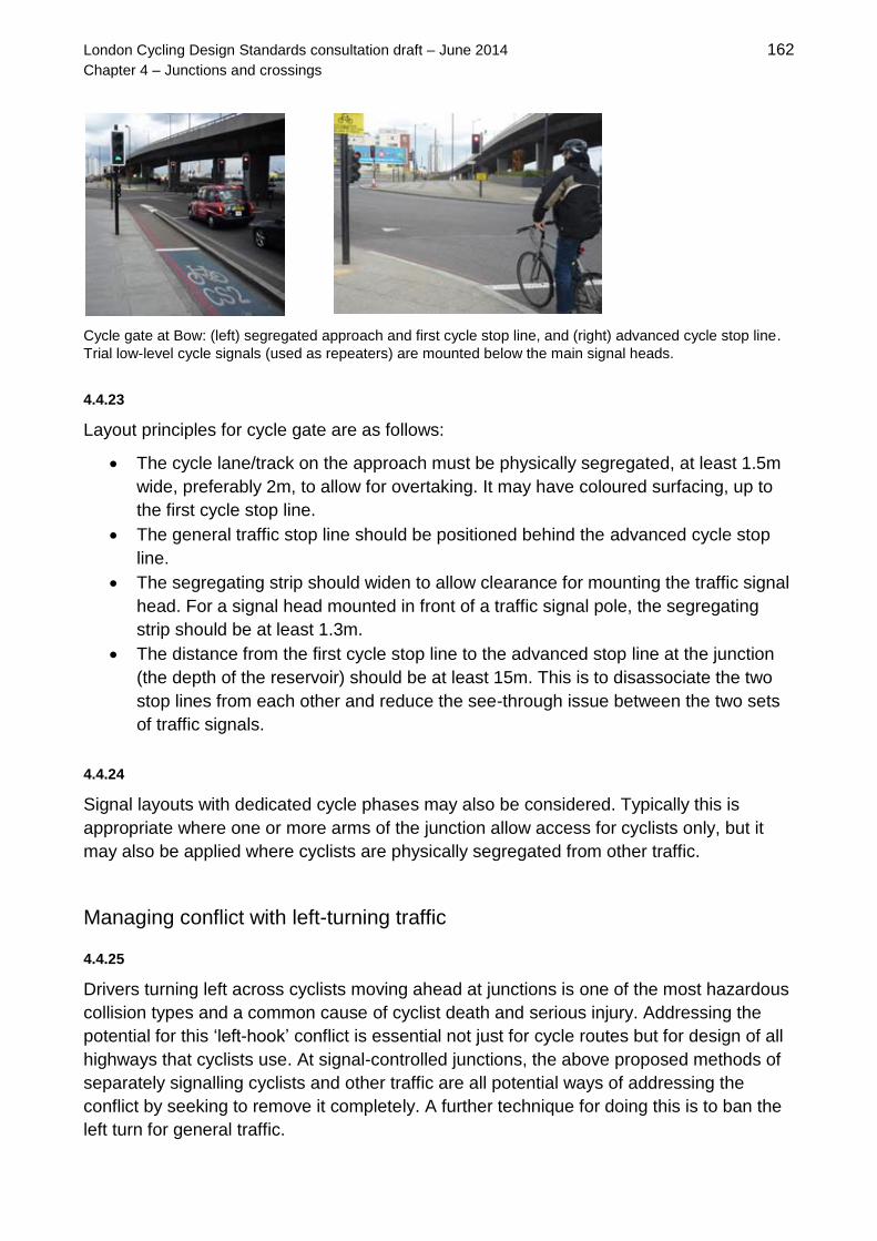
London Cycling Design Standards consultation draft – June 2014 162
Chapter 4 – Junctions and crossings
Cycle gate at Bow: (left) segregated approach and first cycle stop line, and (right) advanced cycle stop line.
Trial low-level cycle signals (used as repeaters) are mounted below the main signal heads.
4.4.23
Layout principles for cycle gate are as follows:
The cycle lane/track on the approach must be physically segregated, at least 1.5m
wide, preferably 2m, to allow for overtaking. It may have coloured surfacing, up to
the first cycle stop line.
The general traffic stop line should be positioned behind the advanced cycle stop
line.
The segregating strip should widen to allow clearance for mounting the traffic signal
head. For a signal head mounted in front of a traffic signal pole, the segregating
strip should be at least 1.3m.
The distance from the first cycle stop line to the advanced stop line at the junction
(the depth of the reservoir) should be at least 15m. This is to disassociate the two
stop lines from each other and reduce the see-through issue between the two sets
of traffic signals.
4.4.24
Signal layouts with dedicated cycle phases may also be considered. Typically this is
appropriate where one or more arms of the junction allow access for cyclists only, but it
may also be applied where cyclists are physically segregated from other traffic.
Managing conflict with left-turning traffic
4.4.25
Drivers turning left across cyclists moving ahead at junctions is one of the most hazardous
collision types and a common cause of cyclist death and serious injury. Addressing the
potential for this ‘left-hook’ conflict is essential not just for cycle routes but for design of all
highways that cyclists use. At signal-controlled junctions, the above proposed methods of
separately signalling cyclists and other traffic are all potential ways of addressing the
conflict by seeking to remove it completely. A further technique for doing this is to ban the
left turn for general traffic.

London Cycling Design Standards consultation draft – June 2014 163
Chapter 4 – Junctions and crossings
4.4.26
It is possible to reduce the risk to cyclists substantially at signal-controlled junctions by
managing the conflict rather than by completely removing it. The best method is to calm
traffic movement through the junction. In many cases, particularly on local streets, city
streets, town square and city places, or in 20mph zones, improvements focused on
controlling traffic speeds such as tightening of junction geometry and use of junction tables
can allow cyclists and slow-moving motor vehicles to move through junctions comfortably
and with reduced risk of conflict. In low-volume and low-speed traffic conditions, ASLs and
feeder lanes can be of clear benefit to cyclists, allowing them the advantage of an
advanced position at the junction itself.
4.4.27
Other scenarios, particularly those on street types with a higher movement function, will
require more substantial intervention. A particular is posed by left-turn general traffic lanes
and free-flowing entry and exit slip lanes for left turning vehicles. Reduction in vehicle
speeds, particularly on the turning movements, may help, but it is also advisable to seek to
reduce the distance where cyclists are vulnerable and move the point of potential conflict
away from the junction itself.
4.4.28
The ideal solution is the removal of slip lanes by reconfiguring the junction, which can also
release significant space for pedestrian and urban realm enhancements. Where removal
of the slip lane is not feasible, measures to reduce vehicle speeds are recommended. If
they must remain, the length of slip lanes could be minimised by reducing the taper to 1 in
3 for 30mph roads and 1 in 5 for 40mph roads.
4.4.29
Where it is not practical to reduce the taper adequately, then continuing the ahead cycle
lane past the left-turn slip lane will require left-turning vehicles to cross the cycling facility.
This can help deter vehicles from changing lanes at lower speeds and generally raise
awareness of other road users, particularly if the cycle lane is marked prominently.
Guidance set out in the section below on central feeders to ASLs should be followed.
However, it is not an ideal solution and it is advisable to apply it only with caution, and
where traffic volumes and speeds are not high.
4.4.30
Appropriate measures for managing the conflict at the point of crossover will depend on
site-specific conditions such as available width, motor vehicle speeds and flows and mix of
vehicles. Interventions that may be considered include ways of encouraging all road users
to make an early and clear lane choice, avoiding last-minute manoeuvres. This may
involve moving the point of conflict back from the junction. Use of smaller dashed
markings (TSRGD diagram 1010), cycle symbols and coloured surfacing can all help to
highlight the need for cycle priority at that point of conflict.

London Cycling Design Standards consultation draft – June 2014 164
Chapter 4 – Junctions and crossings
Use of dashed lane markings and surface colour to highlight a cycle lane
to motorists seeking to enter a left-turn lane
4.4.31
Where a slip road joins a main road, the cycle lane on the main road should, again, be
continued through the conflict area and highlighted for other road users. Diagram 1003
give-way markings should be used on the nearside of the cycle lane, to require vehicles
joining the main road to give way to cyclists and other vehicles on that road, while diagram
1010 markings should be used on the outside of the cycle lane, with diagram 1057 cycle
symbols at 5m intervals. Coloured surfacing can also help to highlight the conflict area.
4.4.32
Light or island segregation (on the inside of the lane markings on the offside of the cycle
lane, or replacing the lane marking) may be considered as a way of focusing the point of
crossover, encouraging motorists to keep their distance from the cycle lane and adding to
the subjective safety of cyclists.
Concept sketch for a junction redesign involving island protection

London Cycling Design Standards consultation draft – June 2014 165
Chapter 4 – Junctions and crossings
4.4.33
Generally, island separation can be used to manage conflicts with left-turning vehicles,
and could be applied to bespoke junction redesign in order to give protection to cyclists.
Separation of this kind is likely to form the basis for future experimental layouts, in
conjunction with innovative use of traffic signals. Any proposal using these methods
should be regarded as a trial, and an important contribution to developing local and
national standards and best practice for safer junction design.
Support for cyclists making right turns
4.4.34
Many of the above measures are focused on managing conflicts between ahead cyclists
and left-turning motor vehicles. However, making right turns on a bicycle can be even
more challenging. Crossing multiple lanes of traffic, in the same and the opposing
direction, requires assertiveness. It would be of benefit to many cyclists if they could
undertake right turns in a different, more comfortable way.
4.4.35
ASLs can help, by allowing a cyclist to position themselves in an appropriate turning
position ahead of the traffic, but only if the cyclist arrives during a red phase. Where cycle
lanes are segregated, consideration needs to be given to how cyclists can take up an
appropriate position to turn right at a junction. Unless another mechanism for turning right
is provided at the junction itself, then the segregation will need to end ahead of the ASL to
allow cyclists to move into an appropriate position to make the turn.
4.4.36
When faced with a difficult right turn, many cyclists choose to make the turn in two stages
on carriageway. This is an informal manoeuvre and not yet specifically encouraged by
regulations, signage and lane markings, or the Highway Code. However, current off- and
on-street trials in the UK are exploring how it could be used more formally, and supported
through regulations.
Two-stage left-turn marking at junction in Stockholm (left); and cyclists in different streams in Copenhagen
(right) – left turners are heading to the waiting area to the right

London Cycling Design Standards consultation draft – June 2014 166
Chapter 4 – Junctions and crossings
4.4.37
In a informal two-stage turn at
a crossroads, a cyclist crosses
one arm of the junction in an
ahead movement, pulls into
the left and stops next to the
pedestrian crossing studs on
the arm adjacent where they
started.
They then turn through 90
degrees to face their exit arm
and wait for the traffic signals
to allow them a second ahead
movement. In this way, they
can stay on the nearside and
avoid having to move across
lanes of traffic in order to turn
right.
Lanes marked through
junctions can assist cyclists
making two-stage right turns
informally by giving them lines
to wait behind in between the
two stages of their turn.
Informal two-stage right turn from the right-hand arm to top arm
4.4.38
This manoeuvre has a more formal status in some other countries, being the prescribed
way to turn right at larger junctions in Denmark, for example. Road markings and surface
colour are often used to mark waiting areas or lines to assist making the second stage of
the turn – these are seen as supporting measures. Depending on the context, on junction
geometry and on the visibility of signal heads from potential waiting areas, existing UK
road markings could be adapted for this purpose. TfL is planning to trial a specific junction
design that would enable a ‘formal’ two-stage right-turn.
4.4.39
One other option for turning right in two steps, as illustrated in LTN2/08, page 64, is the G-
turn or ‘jug handle’ layout. It may be applied either at a signalised junction – in which case
it tends to be designed with dropped kerbs, shared areas and toucan crossings to allow
cyclists to make part of their right turn off-carriageway – or to make a right-turn off a main
road at a priority junction by moving left into an inset waiting and turning area, or up onto a
shared area.

London Cycling Design Standards consultation draft – June 2014 167
Chapter 4 – Junctions and crossings
Cycle bypass
4.4.40
In some locations, it may be possible to allow cyclists to bypass signals for general traffic
(or to bypass other locations where motor vehicles have to stop). Typically this condition
arises at T-junctions where an ahead cycle movement around a red light for general traffic
does not give rise to any conflicting movements. Some physical segregation through the
junction is advisable in this case. Care must be taken to manage pedestrian/cyclist
interaction.
Contraflow cycle lane bypassing traffic signals
Cycle bypass of motor vehicle security checkpoint
Bypass to traffic signals for left-turning cyclists, Hills Road / Cherry Hinton Road, Cambridge
Banning selected vehicle movements
4.4.41
One option for dealing with conflicts that cannot be resolved in other ways is to ban turns
for motorised vehicles. This can help in design of signal operation at the junction as well
as removing a potential source of conflicting movements. Such a decision, however,
should be taken in the light of a wider strategy for the road network around the junction in
question. Banning a movement in one place could transfer that movement, and a risk to
cyclist safety, to another location. The design should support the ban and be self-
enforcing.

London Cycling Design Standards consultation draft – June 2014 168
Chapter 4 – Junctions and crossings
Lanes marked through junctions
4.4.42
As set out in section 4.3, marking cycle lanes
through junctions in the direction of the cycle
route can be beneficial to cyclists from the
perspectives of directness, coherence and
subjective safety. Depending on the
arrangement of lanes and method of signal
control, it is recommended that TSRGD
diagram 1010 markings (or variant as
necessary) should be considered at signal-
controlled junctions. Although cyclists are not
required to stay within the lane, this method
is mostly likely to be of benefit where it is
acceptable for cyclists to remain on the
nearside for ahead as well as left-turning
movements.
Cycle lane marked through signalised junction
Lane markings and surface colour continued through junctions on Cycle Superhighways – short-dashed
TSRGD diagram 1010 markings are shown in the image on the right and are recommended for use as lanes
through junctions.
Use of coloured surfacing for cycling through junctions
in Copenhagen
Coloured surfacing (without lane markings) used
through a junction on a Cycle Superhighway

London Cycling Design Standards consultation draft – June 2014 169
Chapter 4 – Junctions and crossings
4.4.43
Danish practice includes marking a cycle route through a junction using coloured surfacing
but without lane markings. Strips and patches of coloured surfacing through junctions have
been employed on Cycle Superhighways in London. (Future use of this technique is
subject to completion of a research study and a wayfinding strategy to support
infrastructure delivered through the Mayor’s Vision for Cycling.)
Advanced Stop Lines
4.4.44
Where provision for cyclists is on-carriageway, signalised junctions should incorporate an
advanced stop line (ASL) unless there are over-riding safety or operational reasons not to.
ASLs and associated facilities can be used to give cyclists a degree of priority, and help to
raise driver awareness of cyclists. Research has shown that ASLs have a zero or very low
effect on junction capacity. All ASLs and their access need careful consideration at the
design stage, taking into account the junction layout, traffic flows and movements.
Important considerations include ASL capacity...
...and the practicality and comfort of making right-
turn manoeuvres using the ASL.
4.4.45
ASLs help cyclists to: position themselves in drivers’ line of sight, avoid conflict with left-
turning vehicles (when arriving on a red light), wait away from direct exhaust fumes, and
enjoy a head start over motorised traffic. General design considerations for ASLs are
summarised in figure 4.10.
Figure 4.10 General design considerations for standard ASLs
ASL depth Recommended minimum 5.0m. The consultation draft of TSRGD (2015)
proposes increasing the maximum to 7.5m. Authorisation from DfT may
be sought for 5.0- to 7.5m-deep ASLs in the meantime (TfL has
authorisation for this for TLRN and Cycle Superhighways). 7.5m ASLs
are recommended for higher cycle flows.
Coloured
surfacing
While it is recommended that colour is used in locations of potential
conflict, there is no legal requirement. Use of colour for the ASL box or
lead-in lane depends on the policy of the relevant highway authority.

London Cycling Design Standards consultation draft – June 2014 170
Chapter 4 – Junctions and crossings
Set-back from
pedestrian
crossing
1.7m to 3.0m between advanced stop line and pedestrian crossing
studs. 1.7m is recommended for cycle routes as it has been shown: to
improve compliance by motorised vehicles (except motorcycles), to lead
to cyclists waiting in safer and more visible locations ahead of stationary
traffic, to result in better ASL use and operation generally, and to allow
for tighter geometry at the junction.
Swept path analysis must inform the choice: a greater set-back distance
may be required to avoid encroachment from the swept path of large
vehicles where there are no splitter islands. Alternatively, a part-width
ASL may be appropriate.
Entry to ASL Lead-in lane is recommended,
although gate entry is also possible.
The consultation draft of TSRGD
(2015) proposes a change in
regulations to permit cyclists to cross
the first stop line at any point, meaning
that lead-in lanes and gate entries will
be optional from 2015.
The lead-in lane should be at least
1.5m, although 1.2m is preferable to no
lead-in, depending on the likely level of
encroachment by motorised vehicles.
Lead-in lanes may benefit from colour
and TSRGD diagram 1057 cycle
symbols to discourage encroachment.
Diagram from TSRGD consultation
draft (2015), Table 69, Item 47,
showing ASL without lead-in or gate
entry.
Lead-in lane
type
Can be mandatory or advisory, depending on:
adjacent general traffic lane width – if below 3.0m, encroachment
by motorised vehicles is likely and lead-in lane needs to be advisory
flows of cyclists, motor vehicles and wider vehicles – higher cycle
flows may be used to justify a wide, mandatory cycle lane, while
high flows of wider vehicles mean that wider general traffic lanes
are likely to be needed
the need for consistency of provision on a given cycle route
Lead-in lane
length
Ideally as long as the maximum general traffic queue length during peak
periods. Some protection (for example light segregation) may be
warranted for lead-in lanes.
Adjacent
general traffic
lane width
Minimum 2.5m, and no less than 3.0m where buses and HGVs use the
lane. For high frequency bus routes, combined width of the lead-in lane
and adjacent general traffic lane should be at least 4.5m. Consideration
should be given to lane width reallocation to achieve a lead-in lane.
Longitudinal
lines (edges of
ASL box)
The solid longitudinal lines that bound the ASL box on either side must
be provided, unless that part of the carriageway is delineated by a
raised kerb. In practice, this is usually the case for the nearside and
relates to the offside where there is an island.
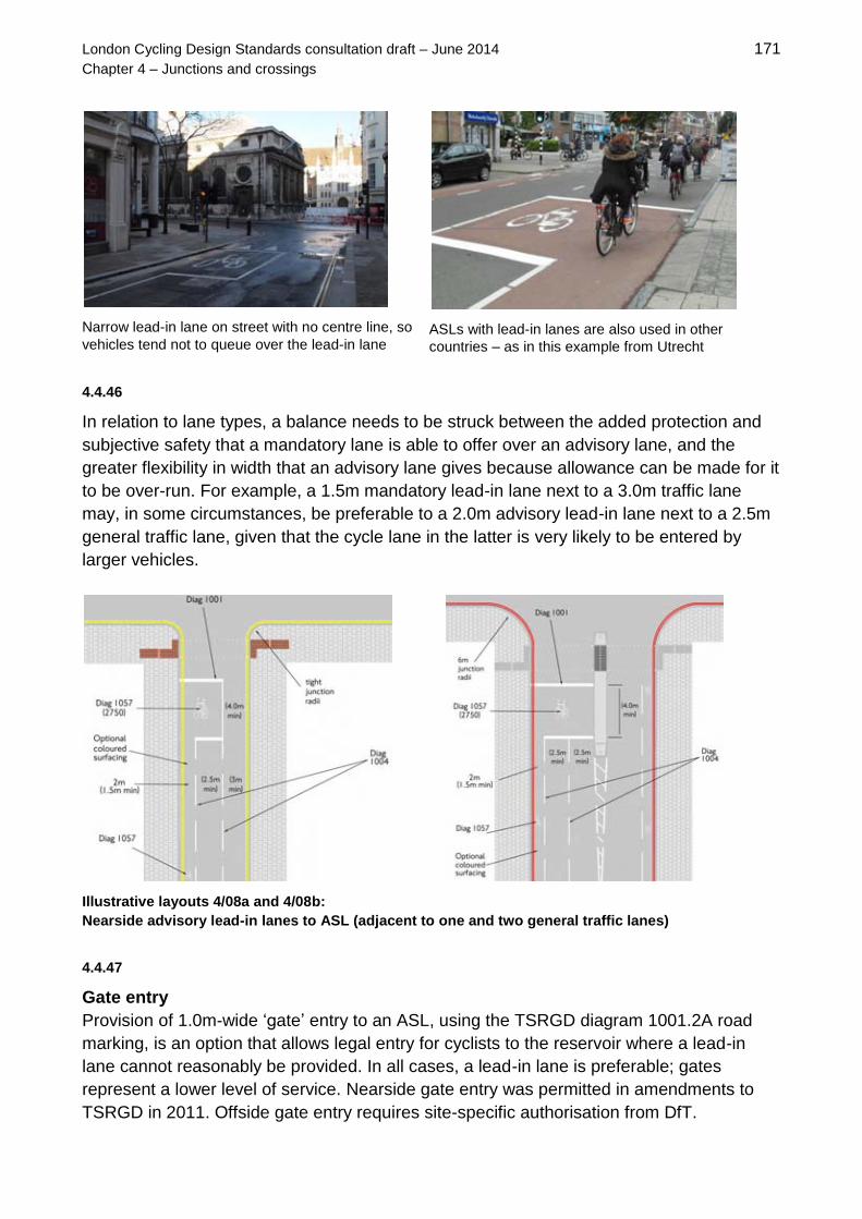
London Cycling Design Standards consultation draft – June 2014 171
Chapter 4 – Junctions and crossings
Narrow lead-in lane on street with no centre line, so
vehicles tend not to queue over the lead-in lane
ASLs with lead-in lanes are also used in other
countries – as in this example from Utrecht
4.4.46
In relation to lane types, a balance needs to be struck between the added protection and
subjective safety that a mandatory lane is able to offer over an advisory lane, and the
greater flexibility in width that an advisory lane gives because allowance can be made for it
to be over-run. For example, a 1.5m mandatory lead-in lane next to a 3.0m traffic lane
may, in some circumstances, be preferable to a 2.0m advisory lead-in lane next to a 2.5m
general traffic lane, given that the cycle lane in the latter is very likely to be entered by
larger vehicles.
Illustrative layouts 4/08a and 4/08b:
Nearside advisory lead-in lanes to ASL (adjacent to one and two general traffic lanes)
4.4.47
Gate entry
Provision of 1.0m-wide ‘gate’ entry to an ASL, using the TSRGD diagram 1001.2A road
marking, is an option that allows legal entry for cyclists to the reservoir where a lead-in
lane cannot reasonably be provided. In all cases, a lead-in lane is preferable; gates
represent a lower level of service. Nearside gate entry was permitted in amendments to
TSRGD in 2011. Offside gate entry requires site-specific authorisation from DfT.

London Cycling Design Standards consultation draft – June 2014 172
Chapter 4 – Junctions and crossings
Illustrative layout 4/09: Gate entry to ASL
Gate entry
4.4.48
Shared nearside lane with gate entry
Where there is left-turning motor traffic and a
gate entry instead of a lead-in lane, cyclists
should be encouraged to adopt a primary
cycling position for the ahead movement. On
Cycle Superhighways, one option to help
promote this is to use full-width coloured
surfacing in the nearside lane, giving an
indication to motor vehicle drivers that they
are entering a space intended for cycling
when they make their left turn.
Shared nearside lane
4.4.49
On Cycle Superhighway pilot routes, use of this method showed no negative effect on
conflicts and an increase in the separation distance between motor vehicles and cyclists,
compared with a non-treated equivalent. This option may be particularly useful where
straight ahead movements from the nearside lane are restricted (eg to buses and/or
cyclists only) and there are high proportions of left-turning motor vehicles. In this situation,
signing to Diagram 877 (see Chapter 6) should be provided to permit specified road users
to proceed ahead at the junction.

London Cycling Design Standards consultation draft – June 2014 173
Chapter 4 – Junctions and crossings
4.4.50
Central or offside lead-in lane
Another option to reduce the risk from left-
turning motor vehicles is a centrally located
or offside ASL lead-in lane. Central feed-in
lanes should be at least 2.0m in width.
Where traffic is expected to be fast-moving,
cyclists will need a safe way of reaching the
cycle lane in the middle of the road, ideally
via continuation of a cycle lane projected
from the start of a left turn flare. The lane
should not be so long between two general
traffic lanes that cyclists are encouraged to
join them where other traffic is fast-moving,
accelerating and/or weaving. One option may
be to use mandatory lane markings for this
lead-in lane with a short section of broken
lane in advance of the junction, thereby
encouraging drivers to cross in a predictable
location.
Illustrative layout 4/10:
Central lead-in lane to ASL
Central lead-in at signalised junction (left). Long central lead-in to allow for left-turn flare, positioned to
facilitate overtaking stopped buses (right).
Offside protection on central lead-in (left). Offside lead-in lane (right)

London Cycling Design Standards consultation draft – June 2014 174
Chapter 4 – Junctions and crossings
4.4.51
Consideration may also be given to protecting cyclists from other traffic changing lanes, or
from the tendency for other traffic not to remain within lane markings around a bend. Small
sections of segregating strips (preferably with battered kerb upstands) may, for example,
be introduced on the off-side of a cycle lane.
4.4.52
Part-width ASLs
In some situations, part-width ASL
reservoirs, not covering the full width of
all the approach lanes, may be
appropriate. They tend to be better
observed by motorists than full-width
ASLs. This includes junctions where:
right turns are not permitted (for
cyclists or all vehicles)
there are multiple right-turning
lanes
tracking of vehicle movements into
the arm of the junction shows that
they would encroach on the ASL
reservoir if it were full-width
a nearside lane is controlled with a
left-turn filter signal
Illustrative layout 4/12: Part-width ASL
4.4.53
General authorisation for part-width ASLs, raised in Signing The Way (2011), has been
proposed in the consultation draft of TSRGD (2015).
Part-width ASL used where right-turning vehicles
would over-run a full-width ASL – Ruckholt Road,
Waltham Forest
ASL across two lanes only from one-way street
(offside lane is a bus lane) – Gower Street,
Camden

London Cycling Design Standards consultation draft – June 2014 175
Chapter 4 – Junctions and crossings
4.4.54
Split ASLs are possible on a single junction arm where movements are separately
signalled and where lanes are physically separated by an island.
Split ASLs with island, Curtain Road, Hackney
Use of a, irregularly shaped ASL reservoir where an
island separates movements
4.4.55
Where there are multiple traffic lanes,
there may be a case for marking
recommended positioning for different
cyclist movements through use of a
split ASL with a dividing line and
direction arrows for cyclists.
A good example would be where there
is a left filter movement for general
traffic that precedes the ahead
movement, and where it would
appropriate to indicate specific suitable
places to wait for cyclists undertaking
different movements. Site-specific or
authority-wide authorisation may be
sought for this technique.
Illustrative layout 4/11: Split ASL
4.4.56
The consultation draft of TSRGD (2015) proposes that ASLs will be prescribed for use at
stand-alone signalised crossings as well as signalised junctions. Until the regulations
come into force, site-specific authorisation will continue to be required for this use.
4.4.57
At junctions with ASLs, blind-spot safety mirrors mounted on signal poles can help give
motorists a better view of cyclists in a lead-in lane on their nearside and in the ASL box.
Blanket authorisation for their use was notified by DfT to local authorities in England in
February 2012 and is confirmed in the consultation draft of TSRGD (2015).

London Cycling Design Standards consultation draft – June 2014 176
Chapter 4 – Junctions and crossings
4.4.58
However, there is currently little evidence
of the safety benefits of blind spot safety
mirrors and trials of their effectiveness
have been inconclusive. There is,
therefore, no general requirement for
safety mirrors on every signal-controlled
junction with an ASL but they should be
considered on a case-by-case basis.
Blind-spot safety mirror showing view of nearside
lead-in lane
4.4.59
Any decision to include blind-spot safety mirrors should be taken by the highway authority,
as they are regarded as signage rather than traffic signal equipment. However, since they
are mounted on signal poles, their installation will need to be considered and assessed by
TfL Asset Management Directorate in a similar way to any other signal equipment – see
section 2.5 for guidance on these procedures. A risk assessment approach should also be
made, with mirrors being most appropriate at junctions with both ahead and left-turn
movements and where there are high cycle and HGV flows.
4.4.60
To achieve the optimum position, and reduce the risk of tampering and vandalism, mirrors
will usually be mounted on the nearside primary signal pole, between 2.4 and 2.5m
clearance above footway level. Ongoing maintenance costs must be considered by the
scheme sponsor.
Bus lanes at signal controlled junctions
4.4.60
Some benefits for cyclists can be achieved by continuing bus lanes up to the stop line at a
junction. This can only be done where there is no left turn for general traffic (unless the
bus lane is separately signalled). This is subject to traffic and safety considerations,
including impacts arising from ahead traffic moving left to pass vehicles waiting to turn
right within the junction.
4.4.61
There may be situations with a bus lane on the approach where an ASL is not desirable,
such as at an intermediate stop line in a multi-junction layout. On the exit from a junction, a
bus lane can re-commence immediately by providing diagram 1010 markings rather than a
taper to give cyclists more protection and deter ‘squeezing’ by merging of non-bus lane
traffic. (Traffic Signs Manual figure 17-1 refers).

London Cycling Design Standards consultation draft – June 2014 177
Chapter 4 – Junctions and crossings
4.5 Roundabouts and gyratories
4.5.1
Roundabouts and gyratories are rarely comfortable facilities for cyclists to use. It is
essential to understand cyclists’ desire lines and manoeuvres in order to provide for their
safety. At many roundabouts, the geometry creates difficulties for cyclists by not
sufficiently reducing motor vehicle speeds. On the other hand, however, the ability to keep
moving through the junction with no loss of momentum makes some types of roundabout,
when well designed, potentially more appealing to cyclists under some circumstances than
signal-controlled junctions.
4.5.2
The ranges of roundabout types, their locations and usage are wide in the UK, and will
have varying effects on cycling. The size of a roundabout, and the volumes and speeds of
motorised traffic they accommodate, has an impact on the subjective safety of vulnerable
road users. Pedestrians also suffer where they are required to undertake circuitous and
often hazardous routes to negotiate a large roundabout. Types are defined in DMRB
TD16/07 (2007), as follows:
Normal – a roundabout with a kerbed central island at least 4m in diameter, usually with
flared entries and exits. Small versions have a single-lane circulatory carriageway. Larger
versions can have multiple lanes, or enough width on the circulatory carriageway and on
the arms to accommodate two or three vehicles alongside one another.
Compact – a roundabout having a central island, with single-lane entries and exits, and
with a circulatory carriageway that does not allow two cars to pass one another.
Mini – a type that has a domed or flush circular solid white road marking of between 1m
and 4m in diameter instead of a central island.
Signalised – a roundabout having traffic signals on one or more of the approaches and at
the corresponding point on the circulatory carriageway itself. Design guidance for
signalised roundabouts is provided in DMRB TD50/04 (2004).
Double – a junction comprising two roundabouts (normal, compact or mini) connected by
a short link and designed as a single system rather than two separate roundabouts.
As a rule, the larger the roundabout, the greater the problems for cyclists. On cycle
routes, large roundabouts should be considered for conversion to a signalised junction or
to a more cycle-friendly roundabout type: a compact or a protected roundabout.

London Cycling Design Standards consultation draft – June 2014 178
Chapter 4 – Junctions and crossings
4.5.3
Most accidents involving cyclists arise from vehicles entering the roundabout and colliding
with cyclists who are on the circulatory carriageway. Interventions that can reduce risks to
cyclists include:
controlling entry, circulatory and exit speeds
reallocating unused carriageway space, such as reducing approach lanes, ideally to
one
providing an alternative route or by-pass for cyclists that does not result in
additional delay
raising driver awareness of cyclists
giving cyclists clear, unobstructed passage up to, through, and leaving the
roundabout
managing traffic and conflicting manoeuvres through the use of signals
reducing motorised traffic volumes
reducing excessive visibility
Normal and signalised roundabouts
4.5.4
Normal roundabouts with single approach lanes and low flows will normally be satisfactory
for cyclists as long as the geometry is ‘tight’. Large conventional roundabouts pose greater
problems for cyclists.
4.5.5
One intervention that has been shown to have safety benefits is to signalise the
roundabout. A study of before and after collision data of 28 roundabouts that had signals
installed found a statistically significant decrease in the number of collisions involving
cyclists (J. Kennedy and B. Sexton, Literature review of road safety at traffic signals and
signalised crossings, TRL, PPR 436, 2009). This report also cites a TfL study from 2003 of
ten at-grade and ten grade-separated junctions, finding significant safety benefits for
cyclists from signalisation for the at-grade types (F. Martin, An analysis of accidents at
roundabouts ‘before’ and ‘after’ signal implementation, London Accident Analysis Unit,
2003).
4.5.6
It is likely, however, that the effect of large roundabouts in deterring most cyclists
outweighs the benefits that signalisation provides. Where roundabouts are signalised,
ASLs can be introduced at signals on the entry lanes and even on the circulatory
carriageway. Cycle early start or cycle gates could also be considered.

London Cycling Design Standards consultation draft – June 2014 179
Chapter 4 – Junctions and crossings
4.5.7
The greatest degree of separation that could be
implemented would be to remove cyclists from
the circulatory lane of the roundabout altogether,
which may be appropriate if the total junction
flows exceed about 25,000 vehicles per day. This
could be done by separating cyclists on each
entry arm, leading them off-carriageway to cross
other arms on parallel pedestrian/cycle or toucan
crossings. In this instance, the impact on
directness and coherence of cycling facilities and
on the potential for pedestrian-cyclist conflict
needs to be balanced with the safety benefits of
removing cyclists from the carriageway.
Off-carriageway cycling at roundabout in
Nantes – motorists give way to crossing
cyclists
4.5.8
Other ways to reduce the risks to cyclists include:
Minimise the number and width of entry and circulatory lanes. More than one entry
lane greatly increases the number of potential conflicts involving cyclists at the
roundabout .Single lane approach and exit widths of between 4.0m and 5.0m, and
single lane circulatory carriageways of between 5.0m and 7.0m are desirable.
Reduce circulatory speeds by introducing over-run strips around the central island
of the roundabout, thereby reducing the width of the circulating carriageway.
Minimise entry and exit flares (between 20º and 60º). Generally, aim to provide
arms that are perpendicular, rather than tangential to the roundabout.
Provide entry deflection to the left on entering the roundabout.
Provide islands to segregate cyclists at entry/exit and greater deflection for
motorised vehicles.
Remove unused carriageway space and increase size of deflector islands while
ensuring pinch-points for cyclists are not created
Provide spiral lane markings for general traffic to improve lane discipline.
Put the whole junction on a speed table, which can help reduce speed on entry and
exit, but is unlikely to make a difference to speed on the circulatory carriageway
4.5.9
As described in DMRB TD50/04, signalised roundabouts vary significantly: some or all of
the arms may be signalised; the signals may be on the external approaches only, or on
both external approaches and on the circulatory carriageway; and the signals may operate
full-time or part-time. Taken together with differences in numbers of arms and lanes, there
are therefore many permutations governing how they operate. Whether they provide good
facilities for cyclists tends to depend on the detail of how potential conflicts have been
managed.

London Cycling Design Standards consultation draft – June 2014 180
Chapter 4 – Junctions and crossings
Mini-Roundabouts
4.5.10
Mini-roundabouts are not recommended for inclusion on cycle routes. The main problems
they raise are failure of vehicles to observe give way due to their geometry and failure to
reduce speed through the junction. Where they exist, they should be considered for
replacement where they have more than one entry lane and/or where there is an angle
approaching 180 degrees between the entry and exit arms (and therefore little horizontal
deflection).
4.5.11
Interventions that could improve existing mini-roundabouts for cycling include:
minimising entry and circulatory widths and speeds
altering geometry to create greater deflection angles
making it impossible for vehicles to overtake within the roundabout circulatory area
reducing single lane carriageway to a maximum width of 5m
raising the central island to 4m diameter to slow general traffic
incorporating a speed table to reduce speeds on entry and exit
incorporating additional deflector islands for motor traffic (and considering omission
of ‘keep left’ bollards from those islands wherever possible, as these can impair the
visibility of turning motor vehicles and their indicator lights – such a proposal should
be subject to a risk assessment).
Compact and continental roundabouts
4.5.12
These two types of roundabout are described, respectively, in DMRB TD16/07 (2007) and
in TAL 9/97, Cyclists at roundabouts: continental design geometry (1997). They can be
useful in addressing cycle and pedestrian safety issues because they reduce motor
vehicle speeds significantly and they prevent weaving and overtaking on the circulatory
carriageway, making it easier for cyclists to adopt the primary riding position around the
roundabout.
Compact roundabout in UK with overrun strip
‘Continental’ roundabout in Lund, Sweden

London Cycling Design Standards consultation draft – June 2014 181
Chapter 4 – Junctions and crossings
4.5.13
As outlined in TAL 9/97, 'continental' roundabouts, which may be suitable for flows of
between 5,000 and 20,000 vehicles per day, are likely to have a positive impact on
cyclists' safety and comfort because:
their tighter geometries encourage all vehicles to take the junction more slowly
they provide only one lane on entry and exit on every arm
the central island is larger relative to the overall size of the junction when compared
to a 'conventional' roundabout, meaning that the entry path curvature of circulating
vehicles is increased (they are deviated more and therefore cannot take the
roundabout at higher speeds)
they are recommended for use in lower speed, lower traffic volume contexts.
They are also advantageous for pedestrians because the tighter geometry allows for
pedestrian crossings on desire lines much closer to the entry to the roundabout than would
be the case for conventional roundabouts.
4.5.14
International best practice shows that
roundabouts of this type may also be
appropriate in situations where cycle flows
are heavy (cyclists comprising a very high
proportion of all traffic). This has been seen
to be reinforced in some instances by
prominent use of the cycle symbol on the
circulatory carriageway.
Roundabout in Nantes, France
4.5.15
Compact roundabouts, as described in DMRB, are similar to 'continental' types, having
single-lane entries and exits, but are tighter still. They are described as being suitable for
roads of 40mph or below, with up to 8,000 vehicles per day. Importantly, the width of the
circulatory carriageway is such that motor vehicles cannot overtake each other. Entries
and exits should be tight, without flares, and the central island may need an overrun area
to account for the movements of larger vehicles. The Irish National Cycle Manual shows a
similar model, the ‘Shared Roundabout’, with cycle symbols on the circulatory
carriageway, but suggests that the maximum traffic flow for such a facility ought to be
6,000 vehicles per day. Roundabout types and attributed are summarised in figure 4.10.

London Cycling Design Standards consultation draft – June 2014 182
Chapter 4 – Junctions and crossings
Figure 4.10 Comparison of roundabout types
Roundabout type
Design feature Normal Continental (TAL 9/97)
Compact (TD16/07)
Mini
Approach arms
Ideally perpendicular but can be skewed
Perpendicular Perpendicular
Preferably perpendicular but can be skewed
Entry width Add one lane to entries
One lane, usually 4m
One lane, usually 4m
Variable
Entry radius 20m, 6m minimum
Not specified but about 10m
Not specified but about 10m
Not specified
Entry angle Preferably 20º to 60º
Approx 30º to 45º
Preferably 20º to 60º
Deflection desirable
Entry path curvature
Not to exceed 100m
Not to exceed 100m
Not to exceed 70m
Exit arms Easy exits Tight perpendicular exits
Tight perpendicular exits
Not specified
Exit radius 40m desirable, 20m minimum
Approx 10m Approx 10m Not specified/max 5m
Exit width Add extra lane Single lane 4-5m
Single lane 4-5m
Not specified
External diameter ICD
28-100m 25-35m 28-36m Dependent on movements
Island diameter Min 4m 16-25m 4-18m (including overrun area)
1-4m
Circulatory carriageway
1-1.2 times entry width
Single lane 5-7m
Single lane < 6m
5-7m
Roundabouts with annular cycle lanes
4.5.16
Cycle lanes around the periphery of roundabouts
have been used in both the UK and other
European countries. They work well where
drivers are accustomed to giving way when
turning, but are more challenging to design in
countries without that cycling culture. They may
generate more problems for cyclists unless the
lanes are particularly wide and the main
problems of vehicle speed and flow are tackled.
Roundabout with annular cycle lane in Utrecht
(sharks’ teeth markings mean ‘give way’)

London Cycling Design Standards consultation draft – June 2014 183
Chapter 4 – Junctions and crossings
4.5.17
Instructing all vehicles to give way on entry to cyclists in the annular lane in the UK could
be achieved through diagram 1003 and diagram 1023 ‘give way’ road markings but this
still requires good driver behaviour.
4.5.18
Motorists are not accustomed to giving way on exit to others on circulatory lanes. Use of
intermittent segregating islands at key points of conflict can help protect circulating cyclists
from collision with motor vehicles seeking to exit.
4.5.19
Increasing the degree of separation of cyclists on roundabouts could be achieved through
the use of more infrastructure, effectively creating segregated lanes around the
roundabout itself. This leaves the problem of circulating cyclist priority over vehicles
entering and exiting from the arms of the roundabout – a similar problem to the generic
issue of lane or track priority across side roads (see section 3.5). Marking parallel cycle
and pedestrian crossings across each arm in such a way that the cycle crossing aligns
with the annular cycle lane is one way of addressing this issue. This will be available when
the revised TSRGD comes into operation in 2015 (see section 4.2).
'Dutch style' roundabouts with segregated cycle lanes
4.5.20
Distinct from the UK definition of ‘continental’ roundabout geometry, this roundabout is a
type where cyclists are segregated from other road users with orbital cycle tracks. 'Dutch
style' roundabouts of this sort typically have one general traffic lane with parallel cycle and
pedestrian crossings on each arm, close to the roundabout itself, to minimise deviation of
pedestrians from desire lines. Where these roundabouts are used in urban areas in the
Netherlands, motor vehicles entering or exiting the roundabout are required to give way to
both pedestrians and cyclists. The geometry is arranged such that motor vehicles leaving
the roundabout approach the crossings at close to 90 degrees to maximise inter-visibility.
4.5.21
A 'Dutch style' roundabout is being trialled off-street by TfL, with results available later in
2014. The focus of the trial is on functionality and safety – ensuring that all users
understand and use the roundabout in the way that is intended, particularly the various
requirements to give way.

London Cycling Design Standards consultation draft – June 2014 184
Chapter 4 – Junctions and crossings
Dutch-style roundabout at TRL test track
Roundabout with off-carriageway tracks in
Amsterdam
Informal roundabouts
4.5.21
Traffic management or speed reduction features that look like roundabouts but without
formal road markings or signage are occasionally used where there is a benefit in
encouraging vehicles to act as if there were a roundabout present. These are a flexible
alternative to priority junctions and are sometimes used as part of a wider shared space-
type approach. There are no set dimensions for such a feature, and they allow for more
creative uses of materials and colour.
4.5.22
Where there is little traffic present, vehicles can progress through the 'roundabout' as they
would at any priority junction. Where traffic is slightly heavier, vehicles are encouraged by
the appearance of the feature to act as if it were a roundabout and give way to the right.
4.5.23
Informal roundabouts can be advantageous to cyclists, allowing them to progress through
a junction without having to stop and start, and generally encouraging lower speeds.
Informal roundabouts at Moor Lane, City of London (left) and Bexleyheath town centre (right), both of which
have a ‘roundabout-like’ feature in the carriageway

London Cycling Design Standards consultation draft – June 2014 185
Chapter 4 – Junctions and crossings
Gyratories and one-way systems
4.5.24
Gyratories in London vary from area-wide one-way systems to large, ‘roundabout-type’
junctions. This variation in types means that each needs looking at on its own merits, as
part of a wider network management approach. It is essential that an area-wide analysis
takes place and that all opportunities for improvements of the local area and for better
pedestrian accessibility are taken into account. The Junction Assessment Tool (see
chapter 2) can assist in analysing cycle movements through various junctions that may
form part of a gyratory.
4.5.25
For cycling, the issues that gyratories and one-way systems present generally include the
following:
motor traffic speed and volume, and close proximity to fast-moving traffic and/or
large vehicles
lack of directness
lack of legibility
the need to move across lanes of moving traffic to get into the appropriate road
position (the confidence to take the primary road position as necessary)
4.5.26
Gyratory removal and a return to two-way working is an option that can help address the
above issues. It is more intuitive, likely to be lower speed, almost always leads to more
direct journeys and can enliven and 'humanise' streets that previously were blighted by
fast-moving bursts of one-way traffic, helping to foster a more diverse range of active
street and land uses. However, gyratory removal should not be an end in itself. The focus
of any gyratory redesign should be on enabling more direct journeys with less delay,
particularly for pedestrians and cyclists, and on allowing more ‘conventional’ approaches
to be taken to cycling provision and to management of motor traffic speed and volume.
This may only entail part-removal or partial remodelling of a gyratory or one-way system.
4.5.27
Other selected interventions can also be made to improve conditions for cyclists. Taking a
filtered permeability approach and allowing cyclists to make movements that are banned
for other vehicles, together with opening up one-way sections to contraflow cycling, are of
obvious benefit for cyclists from a coherence and directness perspective. However, care
needs to be taken to avoid putting cyclists into conflict with fast-moving opposing traffic. A
higher degree of separation, such as use of full or light segregation, might be appropriate
in such cases.

London Cycling Design Standards consultation draft – June 2014 186
Chapter 4 – Junctions and crossings
4.5.28
Where one-way systems are likely to remain,
and where space is available, an opportunity
exists to run cyclists in contraflow around much
of the system. This can constitute a high level of
service, provided each junction within the
system is designed so as to minimise conflicts
and delays for cyclists. It can help in avoiding
issues related to integration with bus
infrastructure.
General traffic lane converted to off-carriageway
tracks at Wandsworth Gyratory

London Cycling Design Standards consultation draft – June 2014 187 Chapter 5 – Street design
Chapter 5
Cycle-friendly street design
5.1 Better places for everyone 188
Good design outcomes for streets 189
Interventions to support cycle-friendly streets 191
5.2 Area-wide improvements for cycling 194
Targeted traffic volume reduction 194
Filtered permeability for cycling 195
5.3 Civilising streets through speed reduction 197
20mph speed limits 197
Homezones and Play Streets 198
Psychological traffic calming 199
5.4 Physical traffic calming 202
Ramps and speed humps 203
Speed cushions 203
Materials for vertical traffic calming 204
5.5 Decluttering and simpler streets 206
Methods of decluttering 206
Removing priorities and sharing space 208
Level surface treatments 210
5.6 Sharing with pedestrians 212
Understanding pedestrian needs 212
Good design outcomes for pedestrian/cycle interaction 214
Degrees of separation 215
Partial separation of users 217
Shared use paths 221
Shared use areas and suggested routes 222
5.7 Integration with bus infrastructure 225
Designing for cyclists at bus stops 225
5.8 Integration with kerbside activity 231
Techniques for integrating cycling with parking and loading 232
Management of on-carriageway loading 234
Loading and parking bays 236
Integration with cycle lanes and tracks 238
Integration with taxis and private hire vehicles 240

London Cycling Design Standards consultation draft – June 2014 188 Chapter 5 – Street design
5.1 Better places for everyone
5.1.1
This section is about creating the conditions for better streets – streets for people, not
streets dominated by motorised vehicles. It covers aspects of good street design that
will benefit pedestrians and cyclists and add economic, social and environmental value
to a neighbourhood. Good cycling infrastructure is not only about designating routes
and putting in cycle lanes and tracks. Many of the best streets for cycling and walking
are those that are calmer, more relaxing places to be.
5.1.2
The sensitivity of many of London’s historic street environments needs to be respected
in designing facilities for cycling that are appropriate to their context. The quality of the
street environment matters as much as its functions, particularly to those on foot and
bicycle. Streets play vital roles in community interaction, commerce and social life and
it is essential they are dealt with by highway engineers and transport planners as
places as well as conduits for movement. As described in chapter 1, street types are a
good way of integrating this place-focused approach into planning of changes to
highways.
5.1.3
Cycle-friendly street design is covered by the Cycling Level of Service Assessment, as
shown in figure 5.1.
Figure 5.1 Key street design considerations in CLoS
Factor Indicator Relates in this chapter to...
Safety:
Collision risk
Kerbside activity or risk of
collision with door
Integration with parking, loading
facilities, bus infrastructure and taxis
and private hire
Safety:
Social safety
Risk/fear of crime
Lighting
Isolation
Impact of highway design
on behaviour
The benefits of making better places
for everyone by designing more
civilised street environments
Comfort:
Deflections
Pinch-points caused by
horizontal deflections
Filtered permeability for cycling,
application and design of physical
traffic calming and other speed
reduction measures Comfort:
Undulations
Vertical deflections
Attractiveness:
Impact on
walking
Highway layout, function
and road markings
adjusted to minimise
impact on pedestrians
Separation from or sharing with
pedestrians

London Cycling Design Standards consultation draft – June 2014 189 Chapter 5 – Street design
Attractiveness:
Greening
Green infrastructure or
sustainable materials
incorporated into design
Area-wide improvements for cycling
and methods of civilising street
environments
Attractiveness:
Minimise
street clutter
Signage and road
markings required to
support scheme layout
Minimising street clutter, particularly in
20mph areas
Good design outcomes for streets
5.1.3
The place characteristics of streets are often seen as the concern of urban designers
and landscape architects but they should also be a core priority for transport planners
and design engineers.
Safety
Design should promote the safe movement of people and goods, and do so in ways
that minimise conflict between road users and contribute to a healthier and more
sustainable environment. Local streets should be designed to provide as safe an
environment as possible for walking, cycling, play and other recreational activities.
Comfort
Street design should accommodate all users, with particular sensitivity to all mobility
and access requirements and with priority for the most energy- and space-efficient
modes. Opportunities should be identified and taken to reallocate under-used
carriageway space to increase space for pedestrians and/or cyclists.
Coherence
Street design should respond to the context, to the character of the local built
environment. Good street environments are legible and can be used intuitively,
irrespective of mobility, by use of appropriate materials and avoiding the need for
excessive signage.
Directness
Wider route opportunities should be provided for modes that require more effort. This
means permeability and flexibility for walking and cycling, minimising journey time for
those modes. Priority should first be given to direct pedestrian access to and from
destinations, and then to cycle access.
Attractiveness
Many aspects of the wider environment contribute to more attractive streets – trees and
other planting, a sense of space and light, good visibility, harmonious use of materials,
historic buildings, land uses that support appropriate levels of activity through the day.
They are essential to a feeling of enjoyment, security and safety as well as aesthetic
integrity, and they make up the sense of place or character that a street is able to offer.
Adaptability
Good street design should deliver value for money, and should take into account life-

London Cycling Design Standards consultation draft – June 2014 190 Chapter 5 – Street design
cycle costs and benefits. Streets should be able to cope with changing functions or
patterns of use without the need for re-engineering. This includes planning for a
changing climate. Permeable surfaces, stormwater source controls and maximising
tree canopy cover can all contribute to resilience to climate change.
Greening at modal filter – Leytonstone
Greening in De Beauvoir Town, Hackney
Trees provide shade on CS3, Cable Street
Public realm improvements – Canning Town
5.1.4
One way in which adaptability, attractiveness and coherence may be supported is by
ensuring that existing materials are retained, restored and reused wherever possible,
particularly in heritage settings such as conservation areas, world heritage sites and in
the vicinity of listed buildings. This may relate to high quality traditional paving (such as
York stone paving) and to granite kerbs, or to street furniture and historic signage.
5.1.5
Streets with a high place function have more active uses, a more diverse range of
demands on space and therefore a greater need to have a more flexible, integrated
approach between different users. Those with a high movement function are more
likely to see separation. The Roads Task Force recommendations also emphasise the
multi-faceted roles that streets play in the lives of Londoners:
as fully accessible public places, a focus for the city's economic, cultural and
social activity

London Cycling Design Standards consultation draft – June 2014 191 Chapter 5 – Street design
as safe places that can help reduce social isolation by supporting the
participation of more vulnerable people in social opportunities
as a major part of the look, feel and reputation of London
providing green and open spaces that support biodiversity and resilience to
climate change
Interventions to support cycle-friendly streets
5.1.6
This chapter covers street improvements relevant to cycling in London and its scope is
summarised in figure 5.2. As covered in chapters 3 and 4, design options for cyclists at
links and junctions depend on the character of streets and on traffic conditions – for
lower speed, more ‘civilised’ streets, wider design options are available. This chapter
also deals with designing for cycling without using cycle lanes, tracks or forms of
separation at junctions. Lower-key forms of intervention are appropriate for large
stretches of the Quietway network as well as being methods of improving quality of
place generally and creating more cycle-friendly streets beyond the network of branded
routes.
Figure 5.2 Summary of cycle-friendly street interventions
Intervention Recommendation Apply to:
Area-wide
improvements
Use of streets with restricted access as part of
the cycle network is recommended to avoid less
adaptable forms of physical infratructure on
mixed streets. Permeability (through-movement)
should be maximised for cycling and walking and
managed for motorised traffic as part of an wider
approach to managing traffic volumes.
Connectors /
High streets / City
streets
Local streets /
Town squares /
City places
Quietways and
Superhighways
away from main
roads
Civilising
streets
through
speed
reduction
Traffic calming offers benefits for vulnerable road
users. The preference is for strategies that use
visual aspects of street design to influence
behaviour and reduce motorised traffic
dominance rather than harder physical
measures.
Physical
traffic calming
In some streets, physical measures are justified
to reduce motorised traffic speeds. These need
to be planned and designed in a balanced way to
reflect the reduction in comfort for cyclists that
they often represent.
Local streets
Quietways and
Superhighways
away from main
roads

London Cycling Design Standards consultation draft – June 2014 192 Chapter 5 – Street design
Decluttering
and simpler
streets
When well designed, interactions between road
users may be improved by removing traffic
management infrastructure such as signals,
traffic signs and road markings. This encourages
road users to negotiate the environment more
carefully, with greater awareness of others and at
lower speeds.
High streets / City
streets / Local
streets / Town
squares / City
places
Quietways
Sharing with
pedestrians
The preference is for dedicated cycling
infrastructure but there will be areas where some
sharing is the most pragmatic choice for the
place. This needs to be done in a way that
minimises potential conflict and is legible and
coherent for all users.
City hubs / City
streets / City
places
Quietways and
Superhighways,
only as a last
resort
Integration
with bus
infrastructure
Since bus routes and bus stops exist on many
streets in London, strategies are needed to
integrate cycling in ways that support the priority
of both modes.
High roads /
connectors
Superhighways
Integration
with kerbside
activity
At route planning and detailed design scales, a
balanced approach is needed towards parking
and loading. In some places, kerbside activity
may need reconfiguring. On streets where
parking and loading remain in their existing form,
specific design strategies for cycling are needed.
All street types
Quietways and
Superhighways
5.1.7
Design of street environments should take into account other national and local design
guidance, including TfL's Streetscape Guidance and borough design guidance at the
local level, and Manual for Streets, Manual for Streets 2, the Design Manual for Roads
and Bridges (DMRB) and the Traffic Signs, Regulations and General Directions
(TSRGD) at national level.
5.1.8
Advice set out in Manual for Streets should inform decisions around the options for
street interventions set out in figure 5.2. Manual for Streets advocates a more
integrated, collaborative process: figure 5.3 sets out key considerations for stages in
the street design process.

London Cycling Design Standards consultation draft – June 2014 193 Chapter 5 – Street design
Figure 5.3 Key considerations in street design process (based on Manual for Streets)
1. Policy review 2. Context
appraisal
3. Detailed design
issues
4. Implementation
and ongoing
management
Planning policy
and area-based
strategy
Community
priorities
Existing or
proposed design
guidance or
codes
Identified road
safety issues
Bicycle, bus,
HGV and
emergency
service vehicle
routes
Street network
Demand and
usage patterns
(including trip
generators)
Accessibility
Street character
types / form, scale,
pattern and
character of
streets
Environmental and
public space
conditions
Land uses and
types of user
Balance of local
versus through
traffic
Access
management (side
streets and private
accesses)
Target and design
speeds
Alignments and
widths
One- / two-way
operation
Horizontal and
vertical geometric
elements
Public space
Materials
Gradients and
drainage
Utilities, lighting and
street furniture
Trees and other
vegetation
Stormwater controls
Speed limit
Traffic controls
Road safety
Enforcement
Access controls
Regulation of
parking and loading
Maintenance and
cleaning
Inspection regimes
Other short-term
operational
improvements

London Cycling Design Standards consultation draft – June 2014 194 Chapter 5 – Street design
5.2 Area-wide improvements for cycling
5.2.1
Design and quality of place influence the ways people choose to travel. Routes that are
lightly trafficked or free from use by motorised vehicles are very attractive for cyclists as
well as pedestrians. Delivering these conditions depends on taking area-wide approach
to traffic management in order to achieve targeted traffic volume reduction on certain
routes and streets. As part of this approach, local interventions such as selective street
closures can be applied to make streets more permeable (easy to move through) for
non-motorised modes but restricted to motorised traffic.
5.2.2
Area-wide traffic management and targeted traffic volume reduction is recommended
for Quietways, where routes are likely to pass through areas that could see wider
benefits from greater management of through-traffic. These approaches are less
relevant for Superhighways although some routes may run away from main roads and
through quieter areas.
Targeted traffic volume reduction
5.2.3
Area-wide approaches taken at the planning stage are covered in chapter 2. This
section deals with the detailed interventions that contribute to larger scale traffic
management. Street types that are more likely to be amenable to targeted traffic
volume reduction and cycle permeability measures are those with lower movement
functions and higher place functions, such as: local streets, town squares, city places
and city streets.
Cyclist exemption from ‘no through road’
Contraflow cycling in one-way street
5.2.4
In urban areas where there is a dense grid of streets, adaptations can be made to
dedicate or restrict through-routes to selected users. Options for more permeability are

London Cycling Design Standards consultation draft – June 2014 195 Chapter 5 – Street design
more limited in other urban scenarios – for example, strategic routes with few side
streets, areas where major land holdings, rivers and infrastructure such as railway lines
cause severance, and one-way traffic systems. The ways in which targeted traffic
volume reduction may be used in support of cycling are summarised in figure 5.4.
Figure 5.4 Summary of methods for targeted traffic volume reduction
Point closure
to through-
traffic
A Traffic Regulation Order (TRO) is required. Point closures are
used to close streets to general traffic, usually maintaining motor
vehicle access to properties, while keeping them open for cyclists.
(See ‘Filtered permeability’ below)
Making two-
way streets
one-way to
general traffic
A TRO is required. Streets should remain two-way for cycling using
contraflow facilities (see section 3.3). A new one-way street may
need additional traffic calming measures as one-way traffic speeds
can be higher than two-way.
Bans and
turning
restrictions
A TRO is required. Where selected movements are banned at
junctions, cyclists should be exempted. Additional local measures
may need to be taken to ensure the cycle movement can be made
safely.
Height, width
and weight
restrictions for
HGVs
Subject to considering the need for freight access and deliveries,
these can be used to limit the number of HGVs on a given street.
They are most likely to be more effective when supported by
physical restrictions. Cycle by-passes to width restrictions may be
appropriate and these should provide a minimum of 1.5m clear
width for cyclists. However, the need for freight access for deliveries
should always be considered.
Signing
strategies
Signs can be used to direct motorised traffic along suitable roads
and away from unsuitable ones such as residential or narrow
streets. It is likely to need complementary traffic calming.
Localised
traffic calming
See section 5.4.
Filtered permeability for cycling
5.2.5
As set out in chapter 2, an ideal network would be one that maximises permeability for
walking and cycling, but exerts tighter controls on through-movement and access for
motorised vehicular traffic. When applied to cycling, this approach is often known as
‘filtered permeability’. This conventionally involves selective point closures to motor
vehicles (or ‘modal filters’), contraflow working for one-way streets, and the use of
linking off-highway paths and routes through green spaces.

London Cycling Design Standards consultation draft – June 2014 196 Chapter 5 – Street design
‘Modal filters’: ways of providing cycle access through places with limited or no motor vehicle access
5.2.6
The minimum clear width (eg kerb-to-kerb or kerb-to-bollard) for cycle access through a
point closure should be 1.5m although a greater width is desirable for two-way cycle
gaps, particularly where cycle flows are high. Consideration needs to be given to
maintaining access for all types of bicycle and tricycle: these types are likely to be
excluded by gaps below 1.5m. Where a larger gap is provided, supplementary
measures to prevent unauthorised use by motorised vehicles should be considered.
5.2.7
Dropped kerbs are needed to maintain level and comfortable access through a point
closure, and are essential for those who need step-free access or for whom pushing a
cycle up a kerb is not an option. Access to dropped kerbs should be at least 1.5m wide,
and proportionally wider when the approach creates an oblique angle.
5.2.8
Safety and security for pedestrians and cyclists need
to be carefully considered where routes are closed to
motorised vehicles. Provided they are well-lit with
natural surveillance, which relies on levels of use and
depends on the wider urban context, they can feel safe
and be safe. Underpasses, alleyways and tunnels can
also provide a good, safe environment for pedestrians
and cyclists when designed with good lighting, clear
sightlines, no dead ends and ideally a degree of
overlooking, or possibly CCTV.
Cycle access through pedestrian-
dominated street

London Cycling Design Standards consultation draft – June 2014 197 Chapter 5 – Street design
5.3 Civilising streets through speed reduction
5.3.1
Traffic speeds impact directly on the risk of serious collisions and the comfort and
attractiveness of cycle routes. Even where cyclists are separated from motorised traffic
lanes, reducing motor vehicle speed limits helps to increase the comfort and
attractiveness of cycling on an adjacent lane or track, particularly if general traffic is
close by.
20mph speed limits
5.3.2
Wherever possible, 20mph should be the maximum speed limit on roads forming part
of designated cycling routes off main roads, including local streets, town squares and
city places. Locations where 20mph limits may be appropriate should be identified and
assessed through the route assessment process (see chapter 2).
5.3.3
Speed limits can be set for individual streets or across zones. Zonal treatments require
measures to ensure general compliance, such as signage and, where appropriate,
physical traffic calming. However, in its guidance Circular 01/2013, Setting local speed
limits (2013), DfT advises that ‘general compliance needs to be achievable without an
excessive reliance on enforcement.’ This is likely to require measures to promote
‘psychological traffic calming’ – see below.
20mph zone in mixed town centre environment
20mph zone signage, Golden Lane, Islington

London Cycling Design Standards consultation draft – June 2014 198 Chapter 5 – Street design
Homezones and Play Streets
5.3.4
Options for traffic calming on local streets include special designations such as
Homezones and Play Streets. While not intended for cycling, these can contribute to
speed reduction generally and to a better balance between road users.
5.3.5
Home Zones give added focus to the non-motorised traffic functions of streets by
redesign of the street environment, often omitting conventional road markings and
using materials that contrast with the wider area to show the street has a different
status. A 10mph speed limit normally applies, which means many cyclists may need to
moderate their speed. DfT provides guidance on Home Zones via two Traffic Advisory
Leaflets: TAL 10/01 Home Zones: planning and design (2001) and TAL 08/02 Home
Zones: public participation (2002).
Homezones in the UK (left) and Germany (right)
5.3.6
Play Streets are temporary closures to through-motorised traffic for a single or
recurring event, allowing people to occupy the carriageway space for activities such as
children’s play. They do not allow cycling during the closure, but they can change
perceptions about the use of the street and, in time, lead to calls for more permanent
redesign of the street environment.
5.3.7
Both Play Streets and Home Zones have a recognised regulatory sign – diagram
numbers 618 and 881 respectively in TSRGD (see chapter 6 for more details on
signage). This formal status allows other road users to recognise the special nature of
the street even, in the case of a Play Street, where there may be no other visual
indication for most of the time that it is different from any other residential street. This
may give rise to more considerate behaviour towards others, particularly vulnerable
road users, and to lower speeds.

London Cycling Design Standards consultation draft – June 2014 199 Chapter 5 – Street design
Psychological traffic calming
5.3.8
The character of the street has a subtle effect on traffic speeds: the street width, lane
widths, the amount of greenery, the sense of enclosure given by the buildings, the
levels of activity and the uses that the street supports. If motorists perceive that they
have unbridled priority and that the street has been designed primarily for through-
traffic, then they will drive accordingly.
5.3.9
A study by TRL, 'Psychological' traffic calming (2005), compared different design
techniques for traffic calming, together with more conventional speed reduction
methods. Uncertainty was observed to be very effective in reducing speed, particularly
‘tree build-outs’. The greatest impacts were achieved using combinations of
psychological and physical measures. Geometry is a key factor: when motorists are in
more doubt about whether the space exists to make a passing manoeuvre, they are
likely to overtake more slowly and more carefully (if at all).
5.3.10
Features that may support this psychological calming effect include:
the appearance of road narrowing and reduction of forward visibility
removal of road markings that give motorists more security than is appropriate,
resulting in excessive speed (typically centre lines on local roads)
use of different materials, colours, street furniture and planting to make the
street environment less ‘road-like’ – this can include, for example, changes in
surface material that give the impression that a raised table exists without the
need for construction of a table
frequent active frontages, with high levels of pedestrian activity
frequent formal and informal crossing by pedestrians
use of the carriageway by large numbers of cyclists
Visual narrowing by use of contrasting materials
for market stall areas – Whitecross Street
Median strip used for visual narrowing and to
enable informal crossing – Hornchurch

London Cycling Design Standards consultation draft – June 2014 200 Chapter 5 – Street design
Illustrative layouts 5/01a and b: Changes in carriageway materials to support visual narrowing
5.3.11
Centre line removal is a simple and effective way of achieving a traffic calming effect
and is recommended for any street with only one general traffic lane in either direction.
Motorists often drive to the centre line and, where advisory cycle lanes are marked on
narrower streets, are more likely to encroach into the cycle lane than the opposing
traffic lane. Removing the centre line encourages them to drive to the advisory cycle
lane marking instead, and tends to have a speed reducing effect because motorists are
more wary of traffic in the opposing direction.
Many calm, two-way residential streets have no centre lines and little width between parking bays

London Cycling Design Standards consultation draft – June 2014 201 Chapter 5 – Street design
Illustrative layout 5/02: Centre line removal to support visual narrowing

London Cycling Design Standards consultation draft – June 2014 202 Chapter 5 – Street design
5.4 Physical traffic calming
5.4.1
Speed reduction through subtle, ‘psychological’ measures are preferred for most
circumstances – particularly Quietway routes. However, there may also be a need for
physical speed control measures as part of area-wide road safety treatments in order
to enforce a speed limit, helping road users to stay comfortably within it.
5.4.2
Cyclists are particularly susceptible to being destabilised by abrupt changes in road
surface level or being made to deviate sharply from their course. For those reasons,
methods of traffic calming designed for motorised vehicles that are a problem for
cyclists include: rumble-strips, steep humps with upstands, sharply angled footway
build-outs, pinch points and ramps with bumpy or slippery surfacing. These should be
avoided on cycle routes, unless the intention is to slow cyclists (see section 3.2, ‘Cyclist
slowing measures’).
5.4.3
Physical traffic calming measures include horizontal and vertical forms. Section 4.3
covers some vertical methods, including junction tables and entry treatments, and
horizontal methods such as chicanes, footway build-outs and refuge islands. Central
hatching, often used to protect traffic islands, should only be used as a speed control
measure where absolutely necessary.
Horizontal calming can be effective, and avoids the comfort issues raised by vertical
calming. However, it must comply with the guidance set out in figure 4.6 of LCDS, to
avoid creating pinch-points for cyclists.
Central hatching used to protect island
– Bathurst Gardens, Brent
Footway build out on street with contraflow
cycling

London Cycling Design Standards consultation draft – June 2014 203 Chapter 5 – Street design
Ramps and speed humps
5.4.4
Speed humps can be very effective at reducing vehicle speeds but need to be carefully
designed so that their presence does not deter cyclists from using the road. Sinusoidal
humps and sinusoidal ramps to tables and entry treatments should always be used on
cycle routes as they allow cyclists to maintain speed and they generate lower levels of
vibration than flat-topped humps. For a level change of 50mm or less, a sinusoidal
profile is not required for the ramp.
Sinusoidal-profile humps
Flat-topped hump
5.4.5
Linear ramp gradients should normally be between 1 in 10 and 1 in 20, although the
legal maximum is 1 in 6. It is recommended that the new surface of the ramps is
continued 500mm beyond the ramp into the existing surface to produce a smoother
profile. Steeper gradients and higher tables will provide greater speed reductions, and
may be suitable for less trafficked roads, but will be more of an inconvenience to
cyclists as well as motorists. Where there are higher flows, then flatter gradients and
lower tables, or sinusoidal ramps may be more appropriate. The TfL note BP2/05,
Traffic calming measures for bus routes (2005) provides further advice in this area.
5.4.6
On routes used by buses, only sinusoidal or shallow-ramped flat-topped varieties of
hump may be used. Humps may not be acceptable on any route used by emergency
service vehicles.
Speed cushions
5.4.7
Speed cushions are often introduced in preference to humps on routes used by buses
and emergency vehicles. They need to be carefully positioned to allow the cyclists to
continue on a line that is at least 0.5m from parked cars and their door-opening space.
The route for cyclists and P2Ws should be clear and direct, avoiding the need for either
to deviate from a direct line, thus causing conflict. This may require parking controls for

London Cycling Design Standards consultation draft – June 2014 204 Chapter 5 – Street design
a short distance either side of the cushion. The nearside gap should normally be clear
of gulleys and 1.2 to 1.5m wide (greater than the 0.7m specified by road humps
guidance). Where frequent parking adjacent to the cushions cannot be avoided, gaps
should fit cyclists’ normal alignment.
Gaps between speed cushions are in line for
cyclists, reinforced by cycle symbol positioning
Gaps force cyclists to deviate from their line and
into the door-opening space of parked cars
5.4.8
The safety and comfort of cycle trailers and non-standard cycles (including tricycles
and handbikes) must be considered when specifying cushions. Unless a nearside gap
of at least 1.5m is provided, then the width of the cushion needs to be sufficient to allow
users of cycle trailers and tricycles to ride over the top of the cushion.
Materials for vertical traffic calming
5.4.9
For low-flow locations, bituminous materials are inexpensive and quick to construct. In
other locations, block-paving tables will give a clearer pedestrian route. If block paving
is used on ramps steeper than 1 in 20 then potentially hazardous deformation is likely
to occur. Contrasting colour or texture will make the feature more visible and have a
greater slowing effect.
5.4.10
Ramps constructed of granite setts can be effective at slowing motor vehicles because
of the rumble effect, although they can be manufactured and laid smooth. The surface
must be smooth enough to be comfortable for cyclists, particularly the (edge) section
most used by them. However, in higher usage situations granite can polish, becoming
slippery and creating stability problems for cyclists and other two wheeled vehicles.
Granite setts are also not likely to be a durable choice of material when frequently over-
run by larger vehicles.

London Cycling Design Standards consultation draft – June 2014 205 Chapter 5 – Street design
5.4.11
Sinusoidal ramps can be constructed with asphalt, block paving or imprint pattern. Pre-
cast concrete units are available but are of a shorter and steeper profile and so should
only be used with caution. Good skid-resistance is important particularly where there
are turning movements.
Sinusoidal ramp in block paving

London Cycling Design Standards consultation draft – June 2014 206 Chapter 5 – Street design
5.5 Decluttering and simpler streets
5.5.1
On most cycle routes, particularly Quietways, it is likely to be beneficial to simplify the
street environment. Not only is this consistent with the idea of psychological traffic
calming – removing features that give the impression of motor traffic domination – but it
also helps in meeting the Mayor’s Vision for Cycling requirement of ‘better places for
everyone’ by making streets more attractive, aesthetically pleasing places to be.
Methods of decluttering
5.5.2
Minimising street clutter is one way of simplifying the street environment, and should be
applied in line with relevant street design guidance, such as TfL’s Streetscape
Guidance. It is particularly important for those street types with a high place function,
such as city hubs, city streets and city places, where the aesthetic integrity of streets
and the need to accommodate multiple functions are a high priority.
5.5.3
Interventions to support decluttering include:
removing and consolidating existing signage whenever feasible
using existing poles, posts, columns, walls and railings along the route for
signage (the net number of signage posts should be the same or less than
previously existed)
using agreed street furniture options and palette of materials to ensure that all
the various elements are in keeping with their surroundings
keeping the variety of materials to a minimum – employing, for example,
changes in colour and surface texture only where it serves both a practical and
aesthetic purpose
co-locating signal heads and lighting on the same column
ensuring that litter bins, control cabinets, other street furniture and trees are
located in the furniture zone adjacent to the carriageway, leaving at least 2m
clear width for walking
removing pedestrian guardrail, unless it is absolutely necessary
attaching street lighting to buildings
removing any inconsistent or unnecessary road markings

London Cycling Design Standards consultation draft – June 2014 207 Chapter 5 – Street design
Minimal use of road markings – Bunhill Row
Decluttered street environment – Liverpool Street
5.5.4
Cycling infrastructure can add extra complications, particularly when it comes to
physical separation or additional demands for signage, signals and surface markings.
To help minimise infrastructure and signage clutter whenever there is a decision that a
higher degree of separation is required:
Consider lighter and intermittent forms of segregation. These are invariably
cheaper and more flexible than continuous forms.
Ensure the street is as legible as it can be. Ideally, people should be able to tell
where motor vehicles, cyclists and pedestrians are supposed to be without the
need for conventional signage to explain the environment. This can often be
done in subtle ways, through changes of material or embedding signage within
surface materials.
Make the street environment intuitive, avoiding wherever possible scenarios
where road users are put into an unfamiliar relationship with one another. Where
the context calls for a more 'unintuitive' layout – such as contraflow cycling or
cyclists and pedestrians sharing space – signage, markings and tactile paving
has to be used to inform road users of how the space operates, and this is likely
to undermine efforts to declutter.
Be consistent with cycling infrastructure. Keep cyclists either in a one-way or
two-way system of tracks for as long as possible without unnecessarily switching
between the two, unless this serves a deliberate strategy of returning cyclists to
the carriageway at junctions and side roads, as is common in Danish practice.
Use only the amount of regulatory signage that is strictly necessary.
5.5.5
Decluttering is consistent with local and national policy. The Mayor’s Better Streets
initiative focuses on practical steps to achieve high quality streets, and advocates a
staged approach. The five stages it describes represent increasing levels of
intervention, with decluttering and merging functions being at ‘easy’ end of the scale.
Manual for Streets takes the view that designers should use ‘the minimum of highway

London Cycling Design Standards consultation draft – June 2014 208 Chapter 5 – Street design
design features necessary to make the streets work properly’ (para 1.1.6, p13). This is
an approach supported by the Department for Transport in Signing the Way, explained
further in TAL 01/13, Reducing Sign Clutter and reinforced in the consultation draft of
the traffic signs regulations, TSRGD (2014).
Removing priorities and sharing space
5.5.6
Stripping back signs, markings and formal traffic management means relying more on
good behaviour, negotiation of movements and sharing. This contrasts with
approaches that warn, instruct, separate and control different movements and, often,
different modes.
5.5.7
Given that it is challenging to integrate new infrastructure and signage with the existing
sense of place and local distinctiveness, it is advisable to start with decluttering in
mind. In some instances, for example on streets with a mix of uses and functions, such
as high streets, city streets and city hubs, design objectives related to changing the
balance between users could be better served not only by seeking to minimise clutter
but also by removing priority between users and promoting more sharing of space. This
is not an approach that is likely appropriate for branded cycle routes, but could form a
linking part of the cycle network through a town centre, for example.
Van Gogh Walk, Lambeth
Byng Place, Camden
5.5.8
In shared spaces, all users negotiate their right of way cooperatively rather than relying
on traffic controls. The street environment can therefore be used more flexibly
throughout the day or for special events, and can support a more diverse range of
uses. Ideally, those active land uses can spread into the surrounding street network,
fostering a vibrant public realm. Comfortable, attractive environments encourage
‘staying’ activities such as relaxing, shopping, eating, socialising and playing.

London Cycling Design Standards consultation draft – June 2014 209 Chapter 5 – Street design
Seven Dials, Covent Garden
New Road, Brighton
5.5.9
The principal sources of guidance on shared space in the UK are Manual for Streets
(2007) and DfT’s Local Transport Note 1/11, Shared Space (October 2011). LTN1/11
stresses that bicycles are vehicles and that the emphasis is on pedestrians not having
to defer to vehicles. It advises that an indicator of sharing is ‘drivers and cyclists giving
way to one another’.
5.5.10
Typical features of shared space include:
removal of traffic management related street furniture, eg. traffic signals and
guardrailing
opportunities for tree planting and/or other soft landscaping
minimal use of signage
indications of priority at minor junctions omitted
low flows of motorised vehicles
low vehicle speeds (LTN1/11 recommends a design speed of 15mph or less)
use of courtesy crossings at surface level instead of controlled crossings
a ‘ladder-grid’ movement pattern – encouraging pedestrian crossing at certain
points, at regular intervals, through subtle variations to the width of the footway
or comfort space
dedicated, carefully designed parking/loading bays
generous amounts of seating
well designed lighting
street trees, street art, cycle parking or other items of street furniture in
‘unconventional’ positions
5.5.11
More vulnerable road users may feel uncomfortable trusting considerate behaviour by
others, particularly those who present a high risk of injury in the event of a collision.
People with visual and physical impairments may feel that they have a much reduced

London Cycling Design Standards consultation draft – June 2014 210 Chapter 5 – Street design
level of subjective safety if they are being asked to share with other road users. How
these types of areas are navigated, particularly by blind and partially sighted people,
needs to be considered carefully as part of the scheme design.
5.5.12
Application of shared space approaches can be an opportunity to promote greening
and use of sustainable drainage. Permeable surfacing should be used wherever
possible and care needs to be taken around the impact on street drainage of any level
changes or changes to surface materials. More detail on this is provided in the section
on shared surfaces, below.
5.5.13
It is important that the transitions to shared space are well designed, so that drivers
enter the space at an appropriate speed. Gateway features, raised tables or continuing
the footway and cycleway across the entrance to the street are all ways that this might
be achieved. Other alternatives include a reduction in road width, visual narrowing, a
change in surface material or, simply, signs and markings.
5.5.14
Design of parking and loading in shared space is important, due to the risk that
stationary vehicles may obstruct movement, although parking can be used
constructively to help frame the pedestrian space and create horizontal deflections that
assist in controlling vehicle speeds. There may be a desire to discourage regular
vehicle movements, so short-term parking bays should be avoided, as should parking
that reduces the width of the pedestrian space.
Level surface treatments
5.5.15
Simplification of the street environment, in support of a
better balance between road users and slower speeds,
may also be served by the use of level surface treatments,
where there is no level difference between footway and
carriageway. Level surfaces usually form part of a wider
shared space approach, but can be applied as a separate
measure, in order to remove a physical and psychological
barrier to pedestrian movement and increase drivers'
awareness of possible pedestrian movement into the
carriageway. They are also often an efficient use of limited
carriageway space.
Level surface on a quiet street

London Cycling Design Standards consultation draft – June 2014 211 Chapter 5 – Street design
Level surface treatment, Coventry
Venn Street, Lambeth
5.3.16
DfT reports in LTN1/11 that level surfaces are appreciated by many people with
mobility, hearing and learning impairments. However, others with mobility and visual
impairments may be disadvantaged by the removal of the obvious physical edge-of-
carriageway delineator that a kerb normally provides. Mitigating measures in such
circumstances will need to include an alternative form of delineation so that the edge of
the footway or comfort space can be perceived. In some places, corduroy tactile paving
is used instead of a kerb (see section 7.3 for further details). Colour and strong tonal
contrast are also important, particularly for visually impaired people. Complicated
surface patterns can be confusing and disorientating.
5.3.17
One alternative option, to achieve many
of the traffic calming and decluttering
effects without the stipulation of a strictly
level surface, is to include a minimal kerb
upstand, usually around 50mm.
Minimal kerb upstands – Church Lane,
Leytonstone

London Cycling Design Standards consultation draft – June 2014 212 Chapter 5 – Street design
5.6 Sharing with pedestrians
5.6.1
This section concerns interactions between cyclists and pedestrians off-carriageway,
particularly the question of whether they can or should be separated or whether they
are asked to share space.
As this guidance makes clear, bicycles are vehicles and the highest levels of service
for cyclists come with dedicated facilities, not areas shared with pedestrians.
5.6.2
International best practice shows that cities with good quality, joined-up cycling
networks do not generally rely on footways shared between pedestrians and cyclists in
inner urban areas. That is not to say that shared facilities might not have their place in
certain circumstances, particularly alongside major arterial roads, but to stress that they
are an option offering a level of provision that ought to be explored only when options
that provide separated space have been exhausted.
5.6.3
In general, it is not desirable to take space from pedestrians to provide for cycling, nor
to create cycling facilities that resemble the footway. However, there may be examples
of very wide or little used footways that may be suitable for reallocation or shared use.
Understanding pedestrian needs
5.6.4
Pedestrians' needs are described in Manual for Streets and Manual for Streets 2. The
key factors that affect pedestrian safety, comfort and behaviour are speed and volume
of other traffic. Various Local Transport Notes have been published by DfT that touch
on these issues, particularly LTN 1/12 Shared use routes for pedestrians and cyclists.
Other key references are the TRL report, Cycling in Motor Vehicle Restricted Areas
(TRL582, 2003) and Phil Jones Associates for Sustrans, The merits of segregated and
non-segregated traffic-free paths: a literature-based review, 2011.)
5.6.5
TfL’s Pedestrian Comfort Guidance for London (2010) is a comprehensive tool to
assess the level of service of footways for pedestrians, based on pedestrian volumes: it
should be consulted in the planning stage of schemes.

London Cycling Design Standards consultation draft – June 2014 213 Chapter 5 – Street design
5.6.6
Any change to the street environment, including those intended to make streets safer
and more attractive for cyclists, must take into account the accessibility needs of all
kinds of users. It is a legal requirement for local authorities to consider the impact of
changes to the built environment on different people. Key sources on this area include
Manual for Streets and DfT, Inclusive mobility – a guide to best practice on access to
pedestrian and transport infrastructure (2002).
5.6.7
Four separate types of disability need to be taken into account in every instance:
Mobility impairment
This describes the use of some form of aid for moving, including wheelchairs, walking
frames and sticks
Visual impairment
This includes blind and partially sighted people, some of whom also use some form of
mobility aid. Visually impaired people tend to use the building line and kerbs as their
main form of navigation
Hearing impairment
This group of people, which includes around 10 per cent who are profoundly deaf, can
have difficulties with balance and so gradients and surface treatments are of particular
significance to them
Cognitive impairment
This refers to people with learning difficulties, which includes age-related impairment.
Some may experience difficulties knowing where they are. Legibility is therefore an
important component of street design for this group
5.6.8
Inclusive design does not stop at dealing with the accessibility needs of people with
these kinds of impairments. Consideration also needs to be given to other typical users
of street environments who may be adversely affected by such things as physical
segregation for cyclists. This includes families with small children, people using push-
chairs and buggies and even people with bulky luggage, which is an important factor at
public transport interchanges.

London Cycling Design Standards consultation draft – June 2014 214 Chapter 5 – Street design
Good design outcomes for pedestrian/cycle interaction
5.6.9
In designing cycling infrastructure, the default should be to separate pedestrians and
cyclists, providing fit-for-purpose, safe and comfortable infrastructure for both. Shared
provision may be appropriate in some circumstances, but only after other options have
been properly explored.
5.6.10
Safety and comfort
Street types and local traffic conditions may justify
a decision to accommodate cyclists on or next to
the footway rather than on the carriageway – for
example on an arterial road or high road.
Pedestrians should always have priority on shared
paths and cyclists should be encouraged to
exercise care and courtesy. Pedestrian-dominated
areas should look different from the carriageway or
dedicated cycle infrastructure, to encourage
cyclists to behave in a way that minimises conflict.
5.6.11
Directness: the role of shared paths in cycling
and walking networks
Where shared use paths are the only practicable
option due to land or funding constraints, it is
usually better to have them to support pedestrian
and cycle movement rather than provide no facility
at all and for them to be designed to be fit-for-
purpose for both users. Failure to complete a key
connection will devalue the remainder of the link
and the cycling and walking networks as a whole.
Shared use path – Hampton Court
Road
Shared use path in Regent’s Park
5.6.12
Coherence (legibility and consistency)
The design of any infrastructure shared between pedestrians and cyclists should be
legible to all users as a priority. Two of the best ways to deliver this are: to avoid
confusing users by switching cycling facilities back and forth from carriageway to
shared use areas, and to minimise use of tactile paving and signage. If large amounts
of tactile paving appear to be warranted, then it is likely that the design is not
sufficiently coherent or legible.

London Cycling Design Standards consultation draft – June 2014 215 Chapter 5 – Street design
5.6.13
Attractiveness
Better conditions for cycling can help to civilise the interaction between cyclists and
pedestrians, removing points of obvious conflict, promoting courteous behaviour on
both sides and alleviating the stressful on-carriageway conditions that lead to some
cyclists acting too assertively when they make sudden shifts into shared areas.
5.6.14
Adaptability: planning for how a space may be used in future
It is essential to base any proposal for changing the physical environment and/or
shifting the balance between users on a comprehensive understanding of how people
currently use the space. This needs attitudinal surveys and views from residents,
retailers, town centre managers, community safety officers, local access groups and
mobility officers as well as data related to flows of different users.
Degrees of separation
5.6.15
As figure 5.6 shows, various degrees of separation between cyclists and pedestrians
are possible. While separating pedestrians and cyclists is desirable in most cases, this
is not an order of preference. Circumstances often dictate that more sharing is a better
option than partial forms of separation, particularly where flows are low, for example on
arterial roads and high roads. Note that design guidance on complete separation is
covered in section 3.3 on cycle tracks and paths.
5.6.16
Pedestrian flows, cyclist flows and speeds, and the desire lines of different users are
important considerations. Indicative flow ranges for cyclists and pedestrians are
provided in figure 5.5 below.
Figure 5.5 Flow categories for shared routes
Level of flow Pedestrians per hour Cyclists per hour
Very low 0 - 120 0 - 10
Low 120-200 10 - 50
Medium 200 – 450 50 - 150
High 450 – 900 150 - 450
Very high 900 + 450 +

London Cycling Design Standards consultation draft – June 2014 216 Chapter 5 – Street design
Figure 5.6 Degrees of separation between cyclists and pedestrians
↑ More
formal
separation
1. Complete separation of users
There are formal, clearly separated
tracks for cyclists, using contrasting
materials (generally asphalt-surfaced)
and/or vertical separation. Pedestrian
movement over the tracks is managed
by formal crossings. It is always clear
who has priority where.
2. Partial separation of users
Physical and visual separation is less
obvious and tends not to last for long
stretches. It is clear who should be
where for the most part but there may
be places where sharing is necessary.
LTN1/12 refers to this type of provision
as ‘segregated shared use’.
3. Shared use with suggested routes
for cyclists
Pedestrians have priority but a cycle
route through a space is ‘suggested’
through material choice and signs
and/or markings. In this way, the right of
cyclists to use the space is asserted.
↓ More
sharing
4. Fully shared use paths and areas
Pedestrians have priority. Cyclists are
allowed to ride, but there is no indication
which part of the space they are likely to
use. Signs are sometimes used to
remind cyclists to ride considerately.
Shared use may be found on the
highway or on links such as railway
paths, riversides, towpaths and routes
through parks.
5. Shared space
No one user has priority. Users
negotiate their way through the space
cooperatively.

London Cycling Design Standards consultation draft – June 2014 217 Chapter 5 – Street design
5.6.17
In most instances where cyclists are permitted to ride through pedestrian priority areas,
much relies on courteous behaviour: cyclists should ride more slowly than they would
in instances where they have priority. Signage telling cyclists that pedestrians have
priority can be helpful, and can bring about more considerate behaviour, but the
preference should be that the environment gives the right cues about behaviour without
the need to impose codes of conduct through additional signage.
5.6.18
Steps should be taken to establish comfortable cycling speeds in shared environments
that is lower than cycling speeds on-carriageway or on off-carriageway tracks. Taking
steps to communicate to pedestrians the legitimate right of cyclists to be in a given
space, and to indicate exactly where those cyclists are more likely to be, can help
reduce the potential for conflict.
Pedestrian priority signage (away from the highway)
Partial separation of users
5.6.19
Partial separation usually takes the form of a line separating an area of footway or
public space between cyclists and pedestrians. A low, raised separator to diagram
1049.1 of TSRGD may be used, between 12mm and 20mm in height, often away from
the highway, through parks for example. Next to the carriageway, where it will usually
have been created by dividing the footway, partial separation is generally only possible
on links, reverting to fully shared areas at crossings and junctions.
5.6.20
Space will tend to dictate whether separating users is feasible. For low flows of both
pedestrians and cyclists (see figure 5.5 for definitions), at least 3m width should be
available, which allows for 1.5m for each user. For high flows, 3m is desirable – so, for
high flows of both users, 6m would be required. If sufficient width is not available,
shared use may be a better option.

London Cycling Design Standards consultation draft – June 2014 218 Chapter 5 – Street design
(Left) Raised delineator and tramline paving indicate the beginning of a cycle track on a partially
separated footway. The symbol in the foreground shows a shared area. (Right) Corduroy paving is used
to bound a shared area at a crossing, with footway for pedestrians only beyond this.
Separated pedestrian/cycle path in
London Fields
High flows of both users in Hyde Park, and a good case
for separation on wide paths
5.6.21
Flows change throughout the day and week, and peaks may not necessarily coincide
with peak flows on the road network. The proximity of schools, residential
accommodation for older people, hospitals, health centres and facilities for disabled
people, for example, can have a significant influence on pedestrian and cycle flows.
Separation on an off-highway route with few
pedestrians. The high wall reduces effective width,
and the cyclist is cycling on the ‘wrong’ side.
There is insufficient width to allocate sides of
this cut-through to different users, so shared
use makes more sense

London Cycling Design Standards consultation draft – June 2014 219 Chapter 5 – Street design
5.6.22
The next question is whether separation is justified. Even if the width is available, there
may be other reasons why shared use might be a better choice. Research shows that
there is little difference in terms of reported pedestrian/cycle conflict between separated
and fully shared paths. Separation is only positive for all users if it actually works: it
would be unwise to assume that all users will notice and comply with more subtle forms
of separation. Non-compliance is quite common, and where and when it occurs, it may
lead to increased potential for user conflicts.
more pedestrians walk on the cycle side when cycle flows are lower
compliance with separation by both users is better during peak commuting times
at other times, when cycle flows are lower and when there is a higher proportion
of larger pedestrian groups using the route, compliance with separation will be
lower
conflict may arise from cyclists seeking to overtake on the pedestrian side when
pedestrians are walking in the cycling side
cyclists ride marginally faster when separated
Some of the pros and cons of shared and separated routes are set out in figure 5.7.
Little distinction between walking and cycling
provision – same level, same surface treatment
Strong visual contrast between adjacent spaces
for cycling and walking (Utrecht).
5.6.23
Appearance is also important. Regardless of how it is designated and signed,
infrastructure that looks like the footway will tend to be used by pedestrians. The
clearest and best understood convention is that paving slabs constitute the footway
and an asphalt surface shows space for cycling. Where that distinction is blurred, then
more confusion is likely. A variety of contrasting surface treatments may be possible:
consistency should be sought within the framework provided by documents such as

London Cycling Design Standards consultation draft – June 2014 220 Chapter 5 – Street design
TfL’s Streetscape Guidance and design guides produced by individual boroughs.
Design approaches that can help reduce confusion include:
use of a separating strip, often a grass verge or other planted strip
difference of level between cycleway and footway
use of contrasting materials
maintaining the separation for as long as possible
Figure 5.7 Comparison of fully shared and separated types of shared use
Fully shared Separated (or partially separated)
Public
satisfaction
and
perceptions
User consultation and public
engagement should emphasise
the opportunities as well as site-
specific challenges
Giving information about detailed
path designs can help build
consensus
User satisfaction tends to
decrease with user age
User consultation and public
engagement should emphasise
the opportunities as well as site-
specific challenges
Public perceptions may favour
separated shared use
Activity and
behaviour
More considerate behaviour
among all users, especially with
code of conduct and coherent
design
Lower cycling speeds at all times
More interactions between users
Could be less potential for actual
conflict and severe collisions
Pedestrians may walk in cycle
track, especially during periods of
low cycle activity
Cyclists tend to comply with
separation unless pedestrians are
in cycle track
Non-compliance with separation
can increase potential for severe
collisions
May be preferred where cyclist
flows are heavier
Priority,
Codes of
Conduct and
Signing
Clear, coherent and consistent
code of conduct may encourage
considerate use, but would need
conveying to other user groups
Supports more effective
management of network
May require greater number of
signs in order to give information
along route
May be less suitable if frequently
intersected by formal and informal
cross-routes, where priority may
not be consistent with path design

London Cycling Design Standards consultation draft – June 2014 221 Chapter 5 – Street design
Physical
design
Efficient use of width
Could enable more sympathetic
design and sense of place
May require more width for a
given level of activity to support
adequate levels of separation at
peak periods
May require more significant
levels of infrastructure
Maintenance Maintenance regime taking into
account seasonal planting growth
and surface degradation
May require more maintenance if
surface is unbound
May require stricter and more
costly maintenance regime to
support suitable separation
Impact of seasonal planting
growth and surface degradation
can adversely affect compliance
with separation
Cost Potentially lower implementation
and management costs
Potentially more costly to
implement and manage
Shared use paths
5.6.24
As a general rule, shared use paths are rarely capable of offering a high level of
service for cycling and should be confined to locations where cycle and pedestrian
flows are low, where space dictates that no better alternative is available or where, as
the above section shows, partial separation might give rise to other potential
drawbacks, such as confusion about who belongs where, lack of consistency or the
use of large amounts of signage and tactile paving.
5.6.25
The main application of shared use paths is on off-carriageway routes such as
Greenways. Sustrans’ Connect 2 Greenways Guide (2009) provides comprehensive
guidance on this kind of facility. Shared use paths alongside the carriageway can also
serve as useful parts of the cycling network, particularly where on-carriageway traffic
conditions preclude good quality, safe provision, as on arterial roads.
5.6.26
Where there are few pedestrians, shared use paths can be attractive for people of all
abilities and are an important way of providing access to facilities for use by people
living locally. In some circumstances, shared use paths may be the only viable option
for completing the network, in which case, the value that they represent in making
traffic-free connections for pedestrians and cyclists usually outweighs any
disadvantages arising from perceptions of conflict.

London Cycling Design Standards consultation draft – June 2014 222 Chapter 5 – Street design
Shared use on a canal towpath
Shared use ‘greenway’ in Stockholm
5.6.27
Consideration of the needs and potential vulnerability of all users of any shared use
path is vital for informing the planning and design process, so that the facility is safe
and comfortable for all. This may include mobility and sensory impaired users,
equestrians, joggers, anglers, maintenance officers (who may also require vehicular
access) and cyclists.
5.6.28
Where investment in cycling improvements results in provision of any new shared use
path, it can be an opportunity to improve pedestrian facilities through better surface
quality and better lighting. The needs of wheelchair users could, for example, be better
accommodated by upgrading an existing footway to be suitable, either in part or as a
whole, for use by cyclists.
Shared use areas and suggested routes
5.6.29
In streets such as city streets, city places and town squares, shared use facilities may
also consist of limited, shared areas of public space, where cyclists are catered for in
areas otherwise dedicated to pedestrians. These can provide important links between
areas dedicated to cycling but need careful design in order to avoid compromising the
safety and comfort of both users.
5.6.30
Typical downsides to this kind of provision include breaking route continuity for cyclists
and having to shift confusingly between areas where different priorities apply.
Pedestrian comfort is also compromised. Shared use areas are therefore at the low
end of the level of service for cyclists. Alternatives may include:
exploring all ways to accommodate cyclists on-carriageway
redesigning an area more comprehensively using shared space principles

London Cycling Design Standards consultation draft – June 2014 223 Chapter 5 – Street design
creating a dedicated cycle track, with some form of physical segregation or
change in level to separate cyclists from pedestrians
using subtle variations in materials to suggest a dedicated cycle route (without
formally creating a cycle track) through what is technically a shared use area
Suggested routes through pedestrian areas: Sutton town centre, Trinity Street, Southwark; Spa Fields,
Islington.
5.6.31
The last of the above options could be applied either to the case of allowing cycling
through ‘pedestrianised’ areas or for shared-use treatments at junctions and crossings.
International best practice shows that this kind of approach is often used to soften the
impact of cycling routes through sensitive areas, either by application of bespoke studs
or cycle symbols, or through variations in surface materials that suggest this is a space
that does not have the same characteristics as the rest of the footway.
5.6.32
Illuminated studs are also used in some places. These have the advantage that they
can be controlled so as to be illuminated at times when more cyclists may be using the
facility. Flexible application of lighting and other markings that help to manage conflict
in shared use areas during certain parts of the day or week could be a good way of
addressing many of the concerns that arise from all sides about these type of cycling
facilities.
Subtle indications that cycling is permitted in a shared area: Munich (left), Stockholm (right)

London Cycling Design Standards consultation draft – June 2014 224 Chapter 5 – Street design
5.6.33
Where it is appropriate to slow cyclists – if, for example, space is limited and cyclists
and pedestrians may be moving in close proximity – surface materials could be used
that have a deliberate slowing effect, such as block paving.
5.6.34
Note that pedestrians continue to have priority in such areas and courteous behaviour
from cyclists is essential if they are to work well, without conflict. Care should therefore
be taken to avoid indicating that cyclists have any priority over pedestrians. Subtly
demarcated routes through shared use areas should stop short of the carriageway at
crossings, so as to encourage cyclists to give way to ‘normal’ pedestrian movement to
continue along the footway.
5.6.35
This should not mean using give way markings. In general, any ‘road-type’ markings on
the footway should be avoided. No matter what the formal meaning of such markings
may be, they tend to give the impression that the rules of the carriageway apply on the
footway. Where necessary, signage may be used sparingly to clarify pedestrian priority.

London Cycling Design Standards consultation draft – June 2014 225 Chapter 5 – Street design
5.7 Integration with bus infrastructure
5.7.1
The needs of buses and bicycles often coincide and there may well be a desire to
encourage and prioritise both on the same street, particularly for street types that are
commonly used for bus routes, such as connectors, high streets and high roads.
Combining provision allows for interventions that benefit two priority road users,
offering directness and coherence to cycling infrastructure, mainly for Superhighways.
Sharing with buses is not likely to be a treatment appropriate for Quietways, although
advice in this section on bus stops is relevant to situations where cycling is provided for
off-carriageway. Guidance on shared bus/cycle lanes may be found in 3.3.
5.7.2
Appropriate provision depends on: carriageway
width, number of traffic lanes, cycle route type,
bus frequency and infrastructure, and other
permitted vehicle types. In suggested order of
preference for cyclists, the following possibilities
exist for integrating buses and cyclists effectively:
segregated cycle lane/track and dedicated
bus lane
segregated cycle lane/track and general
traffic lane (no bus lane)
nearside cycle lane within wide shared bus/cycle lane
cycle lane and general traffic lane (no bus lane)
wide shared bus/cycle lane
narrow shared bus/cycle lane
Designing for cyclists at bus stops
5.7.3
Liaison with TfL is required when developing changes to bus infrastructure. Accessible
Bus Stop Design Guidance (2014) assists highway authorities in the development of
practical and affordable measures to improve accessibility at bus stops. It provides
designers with a wide range of issues that need to be considered when reviewing
individual bus stops and their immediate surroundings.
5.7.4
Options to provide for cyclists at bus stops are largely dependent on the nature of the
general provision for cycling on the corridor, which in turn is influenced by the bus
infrastructure and operation. Factors to be taken into account include:

London Cycling Design Standards consultation draft – June 2014 226 Chapter 5 – Street design
cycle flows, and flow variation during the day and week
general motorised traffic volumes
volume and frequency of buses stopping (including the frequency with which
more than one bus is likely to use the stop at any one time)
the number of bus passengers using the stop at different times
the pedestrian routes to and from the bus stop
access for wheelchair users
5.7.5
In most cases where cyclists are being provided for on-carriageway, they should be
kept on carriageway through the bus stop area, to maintain the consistency and
predictability of cycling infrastructure. The main objective should be to minimise risks
when the bus stop is occupied, while maintaining a reasonable continuity of route. The
continuity of a cycle route can be maintained by marking TSRGD diagram 1057 cycle
symbols around the bus stop cage. This raises the awareness of other road users to
the possibility of cyclists moving out to overtake a stationary bus at the stop.
Space for cyclist to pass bus at bus stop
Cycle lane continued around bus stop cage
Illustrative layout 5/03: Advisory cycle lanes at bus stop

London Cycling Design Standards consultation draft – June 2014 227 Chapter 5 – Street design
5.7.6
In terms of provision, a suggested order of preference by degree of cyclist comfort and
‘protection’ is:
1. bus stop within a ‘wide’, 4.5m+ bus lane
2. bus stop within a ‘wide’, 4m bus lane – widen bus lane if feasible, and provide
appropriate symbols on carriageway at bus stop
3. bus stop within a wide nearside general traffic lane (4m or greater) – provide
appropriate symbols on carriageway at bus stop
4. bus stop within narrow (c.3m) bus lane or narrow nearside lane – undertake a
risk assessment for cyclists based on factors such as geometry, peak period bus
usage, traffic flows, gradient (this can provide a high, medium or low risk for
cycling and will give an indication of the amount of effort and cost that is
appropriate at the location – see below for options)
5. where the bus stop is within a 3.2-3.9m wide bus lane, widen the bus lane to 4m
or greater and provide appropriate symbols on the carriageway at the bus stop
6. if widening is not viable for a 3.2-3.9m lane, consider reducing the bus lane
width and treating as category 4 above
5.7.7
For stops within a narrow (c.3m) bus lane or narrow nearside lane, options to improve
comfort and minimise risk to cyclists include:
adjust the lane width markings so that the stops fits into categories 1-3 (bus lane
or nearside lane is 4m or wider)
widen carriageway to enable a partially inset bus stop so that cyclists can
comfortably pass a stationary bus within the bus lane or nearside lane (with
appropriate on-carriageway symbol)
adjust lane width markings for a wider bus lane / nearside lane, providing
sufficient width to enable a cycle lane or coloured surfacing around the bus stop
– this could be aligned to suit kerbside parking / loading
shorten the bus stop in length if it is longer than standard, subject to an
assessment of the bus stop usage (only likely to be an option if there has been a
reduction in the number of buses serving the stop)
relocate the stop – adjust the position so that it becomes a category 1-3 stop or
relocate into nearby side road if viable
remove the stop altogether – either it is not justified or it can be consolidated
with another nearby stop

London Cycling Design Standards consultation draft – June 2014 228 Chapter 5 – Street design
The last two options are only likely to be viable in exceptional situations. Scheme
designers or promoters should liaise with TfL Bus Network Development and
Infrastructure at the earliest stage if this is being considered as an option. An
evaluation of bus passenger disbenefits will need to be provided in any such
circumstance.
Bus stop bypass at Stratford High Street, showing pedestrian crossing over cycle track in detail
5.7.8
Drawing on successful examples of similar infrastructure in other cities in Europe, the
concept of the bus stop bypass is being developed in the UK as a trial measure. In a
bus stop bypass, a cycle track passes through the bus stop area behind the shelter,
thereby creating an island for passengers boarding and alighting the bus. Layouts of
this solution are currently being assessed and optimised through off- and on-street
trials, with a particular focus on the interaction between cyclists and bus passengers.
5.7.9
The size of the island should be adequate for the number and frequency of bus
services and for current and predicted future pedestrian flows – island capacity is being
tested in off-street trials and further guidance will be provided on this when available.
The priority is to ensure good visibility between cyclists and pedestrians, and between
cyclists and other vehicles when cyclists make a transition from carriageway to cycle
tracks. This is largely dependent on careful siting of the bus stop shelter and by
avoiding obstructive advertising/information panels.
5.7.10
All pedestrians should be confident that they can cross the cycle track safely. The basic
layout trialled off- and on-street includes one central, uncontrolled crossing point. In
some instances, two crossing-points may be warranted to serve pedestrian desire
lines, although it is likely that pedestrians will choose the shortest path available

London Cycling Design Standards consultation draft – June 2014 229 Chapter 5 – Street design
regardless of whether or not a designated crossing point is available. Whether the
crossing needs to have pedestrian priority indicated (ie. give way markings on the cycle
track) in some instances is another variable subject to further trialling.
Examples of bus stop bypasses – clockwise from top left: Stockholm, Seville, Brighton & Hove,
Copenhagen
Illustrative layout 5/04: Bus stop bypass where cycling provision is on-carriageway

London Cycling Design Standards consultation draft – June 2014 230 Chapter 5 – Street design
5.7.11
To help visually impaired users to distinguish between the footway, the track and the
bus waiting area, it is likely to be helpful to use visually contrasting surface materials
and a minimum kerb height for the cycle track of 25mm high. However, kerbs with a
vertical profile can represent a trip hazard for pedestrians or could unseat cyclists if
struck, and they reduce the effective width of the cycling facility. Battered or splayed
kerbs could help to mitigate this problem.

London Cycling Design Standards consultation draft – June 2014 231 Chapter 5 – Street design
5.8 Integration with kerbside activity
5.8.1
Interactions of cycling infrastructure with kerbside activity need to be designed and
managed in such a way as to minimise risks to cyclists while maintaining all necessary
access. This includes design for loading and unloading activity to take place as
efficiently as possible, which is important for street types such as high streets, town
squares, city streets and city hubs which have a diverse mix of land uses, intensive use
of kerbside space and the need for flexibility during the day and week.
Design that successfully integrates cycling, parking and loading needs an appropriate
balance between physical measures and the management of kerbside activity.
Enforcement of measures put in place to deal with competing demands is essential.
5.8.2
Kerbside activity also includes the activities of taxis and private hire vehicles, bus and
coach stops and the provision of appropriate facilities for blue badge holders. Detailed
analysis of existing and likely future needs for all these types of kerbside activity, and
the extent to which they are tied to a fixed location or can be accommodated more
flexibly, should be undertaken during the route assessment and prioritisation stage
(see section 2.3), involving dialogue with those affected.
5.8.3
Considerations for parking and loading are, broadly, as follows:
Creation of dedicated, enforceable kerbside space for
loading or parking requires a Traffic Regulation Order.
In many areas, loading and parking take place on the
carriageway, as indicated by appropriate road markings
and signage showing timings and restrictions.
Single and double yellow lines (or red lines for TLRN)
indicate waiting restrictions, including parking. Waiting is
not permitted at any time on a double yellow line. Single
yellow lines indicate a waiting restriction, operated
according to timings given on adjacent signs.
Signs showing time-limited
loading
Loading restrictions are indicated by yellow or red ‘blips’ marked on the kerb next to a
double line. A double-blip marking means no loading at any time. A single blip indicates
a time-limited loading restriction, which is explained by accompanying signage.
Typically this restricts loading to short 20- or 40-minute periods.
Dispensations may be granted by the highway authority for specific vehicles or for
deliveries for certain premises to take place in spite of advertised restrictions. The
dispensation is usually displayed in the vehicle’s window or incorporated into the local
enforcement regime. These are exceptional and design should limit the need for them.

London Cycling Design Standards consultation draft – June 2014 232 Chapter 5 – Street design
5.8.4
As a basic principle, taking space from the footway is sometimes justifiable for loading,
as part of a flexible approach to using space on a busy street, but should generally be
avoided for parking. At least 2m width must remain clear for pedestrian movement,
depending on existing levels of comfort for pedestrians (DfT, Inclusive Mobility
Guidelines, 2002) while 2.5m is recommended in front of shops (TfL, Streetscape
Guidance, 2009).
Techniques for integrating cycling with parking and loading
5.8.5
Figure 5.8 summarises types of intervention that could be applied to rethinking parking
and loading on a cycle route. In terms of cycle safety and comfort, floating parking and
loading is the option that is likely to provide the highest level of service, followed by
inset bays. Area-wide approaches can be more appropriate in many instances,
particularly when it comes to creation of Quietways. They can be a good way of
simplifying the street environment, enhancing its overall attractiveness. It is important
to understand the detail of local parking, loading and access requirements and to
ensure that the free and safe movement of all users, including cyclists, pedestrians and
powered two-wheelers, is maintained. In general, the default should be to seek to
retain any existing dedicated loading bays.
Figure 5.8 Summary of interventions for parking and loading on cycle routes
Separating
cycling from
kerbside
activity at
network level
Where integrating uses cannot be resolved on a given street, it may
be possible to rationalise parking and loading across an area to
focus it on particular streets, leaving others free of most kerbside
activity. This is likely require rethinking cycle route options at the
route assessment stage.
Mechanisms
for area-wide
management
of parking and
loading
Urban clearways
In these zones, there is no stopping on the carriageway for parking
or loading – they can be time-limited, with hours of operation
provided on signs.
Controlled parking zones (CPZs) prohibit waiting throughout a
defined area. Signs at entry-points to the CPZ show times of
operation and can include ‘no loading’. Other variants include:
resident permit holders only, meter payment or pay-and-display
only, voucher parking or waiting restrictions for goods vehicles.
Restricted parking zones (see below) avoid the need for painted
lines at the kerbside by allowing parking and loading subject to
restrictions shown by signs.

London Cycling Design Standards consultation draft – June 2014 233 Chapter 5 – Street design
Relocation of
parking and
loading locally
For cycle routes, it can be beneficial to move parking and loading
away from main routes and onto side streets. Certain types of
loading activity are more amenable to being moved than others,
while the extent to which parking can be relocated depends on
consultation with businesses and residents whose needs are
served by that parking. (See ‘Management of on-carriageway
loading’ below)
Floating
parking and
loading
Where segregated or light segregated cycle lanes/tracks are used,
parking and loading could be included in bays ‘floated’ away from
the cycle track (potentially inset into segregating islands). Where
cyclists are accommodated between the footway and
parking/loading facilities, allowance needs to be made for the
‘dooring zone’ and the kerb height and profiles, all of which of which
may reduce the effective width for cycling. (See section 3.2,
‘Segregation using car parking’)
On-
carriageway
loading/parking
bays
Kerbside activity may be rationalised by creating dedicated bays
rather than allowing parking and loading generally on a street. This
allows kerbside activity to be focused at particular locations and for
cycling infrastructure to be designed around it. Bays may be
defined by built-outs, planting or other streetscape features. (See
‘Loading and parking bays’ below) This may also require re-marking
of cycle facilities around existing parking/loading areas, changes to
the timing of restrictions or minor reallocation of carriageway space.
(See ‘Integration with lanes and tracks’ below).
Inset loading/
parking bays
Although likely to require a more extensive redesign of the highway,
this is a good option for cycling, and can be one that invites a more
flexible use of space, with inset bays effectively forming part of the
footway when not in use. However, they may not be suitable for all
types of delivery. (See ‘Loading and parking bays’ below)
5.8.6
Restricted parking zones, which require a TRO, can be
applied where a restriction is uniform and where
exceptions can be captured easily in signage. They avoid
the need for yellow or red line markings or kerb markings,
and so they can contribute positively to more attractive,
less cluttered streets. The balance to be struck is whether
this justifies the extra signage that needs to be put up at
each entrance to the zone. Many types of restriction are
possible but the recommended way of using restricted
parking zones in support of cycle infrastructure is to
permit parking and/or loading in designated bays only.

London Cycling Design Standards consultation draft – June 2014 234 Chapter 5 – Street design
Management of on-carriageway loading
5.8.7
Any decision about changing loading arrangements should go through a robust
process to allow for different stakeholders to have an input, and for considerations such
as the availability and suitability of alternative facilities to be taken into account. This is
described fully in TfL’s Kerbside Loading Guidance (2009), which describes a hierarchy
of considerations for making changes to loading. The Freight Environment Review
System is a useful tool for scoping levels of risk associated with freight activity.
5.8.8
Existing loading practices should be assessed to see where scope for change exists,
including where deliveries cannot be catered for within present facilities. Options for
rethinking loading include:
A Delivery Point Assessment, which may be undertaken to encourage operators
to make best use of the available facilities.
Delivery and Servicing Plans can be implemented, in order to coordinate and
manage deliveries and make better use of limited delivery space. These plans
are owned and managed by the premises where the deliveries are being made.
Loading restrictions and timings may be reconsidered and revised as necessary,
recognising that land use and delivery activity change over time. The need for
change might be informed by looking at the time and location of freight-related
penalty charge notices, indicating where there is an existing mis-match between
loading provision and demand.
Deliveries to multiple premises could be consolidated in one location.
Better enforcement of existing arrangements can be sought.
Facilities shared with other street users, such as taxis and coaches, could be a
more efficient use of space.
To avoid peak demand and more congested periods, deliveries could be
‘retimed’ to out-of-hours slots. Social impacts need to be considered with this
option, which are often already accounted for through noise abatement notices
or planning conditions (see DfT/Freight Transport Association, Delivering the
Goods: a toolkit for improving night-time deliveries). Note that the London Lorry
Control Scheme limits noise pollution in residential areas at night by restricting
the movement of HGVs overnight and at weekends. The scheme is enforced by
London Councils and applies to vehicles weighing more than 18 tonnes.
5.8.9
The size and location of loading facilities needs to be taken into account in considering
these options. Loading activities can cause congestion by blocking the flow of traffic,
including cyclists. The time, frequency and volume of the activities taking place, and

London Cycling Design Standards consultation draft – June 2014 235 Chapter 5 – Street design
the physical location where loading is permitted, all have an impact. Consideration
needs to be given to access to loading facilities and the potential for reversing vehicles
to impede the flow of traffic and increase the risk of conflict.
5.8.10
The potential for moving, consolidating or redesigning loading bays depends on the
goods being transported. For example:
Cash-in-transit requires vehicles to stop as close as possible to the delivery
point and for the driver to have a clear line of sight to the delivery point, for
reasons of safety and security. Where fit-for-purpose facilities are not provided,
drivers are likely to choose to stop in any location that they deem to be safest,
regardless of any dedicated loading provision that exists in the area.
Deliveries made by the brewery trade require that vehicles may stop at 90
degrees to and a minimal distance from the cellar door, so as to avoid moving
heavy barrels over a long distance. Where vehicles are side-opening, as is the
case with drays used by the brewery trade, the adjacent kerbside also needs to
be free of any street furniture that would obstruct the path of the delivery.
Manoeuvring heavy items can damage the surface of the carriageway or cycle
track, thereby increasing the maintenance requirement.
Goods in roll-cages will require dropped kerbs to allow access over kerb-
segregated or stepped tracks.
5.8.11
Loading can only be expected to take place on a side road where there are no width,
height or weight restrictions that would prevent it and where any resulting reversing
movements can be managed in such a way as not to constitute a hazard to other road
others. At side roads, large vehicles will also need an adequate turning radius to
manoeuvre without over-running the footway. This requirement needs to be balanced
with safety and the advantages to pedestrian and cycle movement and quality of public
realm that arise from tightening corner radii. Where occasional incursion of large
vehicles into other vehicle lanes for the purposes of turning can be accommodated
without undue risk to the safety of other road users, this is preferable to increasing the
corner radii at the side road.
5.8.12
The use of bollards is not recommended and should be avoided where bays are shared
use or where they obstruct loading to /unloading from side-opening vehicles. In
exceptional circumstances where bollards are used they must not become obstacles
for pedestrians: consideration needs to be given to people with visual impairments.
Where used, bollards should be aligned with existing street furniture to provide a
pedestrian ‘channel’.

London Cycling Design Standards consultation draft – June 2014 236 Chapter 5 – Street design
5.8.13
Segregated cycle lanes/tracks will generally preclude all loading activity, unless it takes
place in marked bays on the offside of the cycle tracks and involves goods that can be
delivered across the tracks. Much depends on the type and width of cycling facility and
on the goods being delivered. Where there are wide, stepped tracks, for example, off-
peak loading of lighter items could take place half on the cycle track – this is observed
in many leading cycling cities.
Loading across stepped tracks with low step up from the carriageway – Utrecht (left), Copenhagen (right)
Loading and parking bays
5.8.14
Dedicated parking and loading bays can be useful for managing and localising kerbside
activity. They may be marked on-carriageway, fully inset into a footway, verge or
segregating island, or half-in / half-out. The choice depends to a large extent on
available carriageway width and the likely impact on the general traffic flow.
5.8.15
Parking bays for cars, taxis and motorcycles are a minimum of 1.8m wide. Loading
bays require a minimum of 2.4m, while the minimum dimensions of a bay for blue
badge holders is 6.6m by 2.7m.
5.8.16
The location and size of bays also varies for certain goods and certain vehicles.
Vehicles with a rear tail-lift will require more clear space at the rear than curtain-sided
vehicles, but the latter may require more footway space to the side. Further information
on space requirements is provided in TfL’s Kerbside Loading Guidance (2009).

London Cycling Design Standards consultation draft – June 2014 237 Chapter 5 – Street design
5.8.17
On-carriageway bays are indicated by a broken line around the boundary of the bay
and marked on the carriageway side, for example with ‘LOADING ONLY’. White lines
indicate that loading can take place for an unlimited length of time during the
designated hours, while red or yellow lines indicate a restriction on the duration of
loading. Variations include bays that allow for mixed uses at different times of day,
such as taxis, police and ambulances, as well as waiting and loading. In these cases,
broken yellow lines are used, and restrictions must be explained by signage.
5.8.18
Fully inset bays have the advantage of keeping the carriageway clear and can help in
accommodating multiple uses on the same street, particularly within the high street, city
street and city hub typologies. They can generally be operated with fewer restrictions
than bays marked in the carriageway and, when not in use, they can act as part of the
footway, depending on levels and surface treatment. Control over the hours of
operation can allow for a single bay to be used for loading for part of the day and short-
term parking at other times. It needs to be made clear in the parking enforcement plan
that it is acceptable for vehicles to stop with a wheel on the footway, as this behaviour
otherwise can result in a penalty charge notice.
Inset bay, Wallis Road, Hackney
Loading bay inside advisory cycle lane
Inset loading facilities to support an office
building – Milton Street, City of London
Fully inset loading bays to support retail premises –
Long Acre, Covent Garden

London Cycling Design Standards consultation draft – June 2014 238 Chapter 5 – Street design
5.8.19
Inset bays may be at carriageway or footway level. Where fully inset and at footway
level, they should be within the street furniture zone and accessed over a kerb upstand
of at least 25mm. A minimum nearside lane width of 3.0 metres is required alongside
any inset bay to maintain safe traffic flow.
5.8.20
Where footway width does not allow fully inset bays, half-on, half-off facilities can be a
good compromise. In these bays, vehicles are allowed to stop with their nearside
wheels on the raised footway. They should not be used where they narrow the
remaining width of the nearside lane to between 3.2 and 3.9 metres.
Inset parking bays. Left to right: Montague Street bay; Monmouth Street bay; Russell Square footway-
level bay.
Integration with cycle lanes and tracks
5.8.21
To maintain the safety, comfort, coherence and directness of cycling infrastructure,
loading and parking should, wherever possible, not be permitted in cycle lanes and
shared bus/cycle lanes during their hours of operation. Advisory cycle lanes that are
regularly blocked by vehicles are a poor quality facility and very often worse than no
dedicated cycling facilities at all. Mandatory cycle lanes where parking and loading
restrictions are not enforced are equally unacceptable.
5.8.22
Operating hours need to be determined with reference to anticipated demand and to
the conditions that cyclists may experience outside of the times of operation. 24-hour
mandatory lanes are preferred, although there may be substantial benefit in simply
adjusting hours of operation. Cycling peaks have been observed to begin earlier and
end later than peaks for other modes of transport: indicatively, 6am to 10am and 4pm
to 8pm. Lane operation until 8pm, either through extending the hours of bus lanes
and/or extending parking restrictions for a further hour, could therefore constitute a
much more effective facility for both cyclists and buses during the evening peak.

London Cycling Design Standards consultation draft – June 2014 239 Chapter 5 – Street design
5.8.23
Traffic lane widths are important when it comes to cycling provision outside parking or
loading bays, particularly where those lanes are narrow and larger vehicles are likely to
encroach on (advisory) cycle lanes. Where cyclists are required to move out and
around an obstruction such as a parked car or a delivery vehicle, the principal
considerations should be that they have time and space to make that adjustment, and
that they are not put into conflict with other moving vehicles in doing so.
5.8.24
Where there are no marked cycle lanes, bays should be designed and located so that
at least 3.9 metres width is still available, allowing moving vehicles to overtake cyclists
moving past a bay at a safe distance. Traffic speed calming measures may be
appropriate in such circumstances. If this width is not available, then traffic lanes
should not be in the range 3.2 to 3.9m. Where there are narrow (less than 3.2m-wide)
lanes, use of TSRGD diagram 1057 cycle symbols, centrally placed on the carriageway
ahead of a bay, can help in encouraging cyclists to move out from the kerb well before
the bay itself and take the primary position, and in raising the awareness among
motorists of cyclists needing to move out from the kerbside.
Indicative layout 5/05: Options for marking cycle lanes around on-carriageway parking bays
5.8.25
Cycle lanes marked on the outside of on-carriageway or half-inset loading or parking
bays will usually need to be advisory so that they can be crossed, and at least 1.5m
wide. A buffer zone of 0.5-1.0m should be provided to protect cyclists from the risk of
‘dooring’. This arrangement should not be used if it narrows the usable carriageway in
such a way as to mean that motorists frequently encroach on the advisory cycle lane:
diagram 1057 cycle symbols should be used around the bay instead.

London Cycling Design Standards consultation draft – June 2014 240 Chapter 5 – Street design
5.8.26
In design of cycling facilities adjacent to parking and loading, consideration should be
given to the blind spot areas immediately in front of and to the side of larger vehicles.
Drivers rely on indirect vision aids (ie. mirrors) but some older vehicles are exempt from
the requirement for class IV and V mirrors, which improve vision at the front and
nearside of the vehicle. Note that the Safer Lorry Scheme is aimed at addressing this
issue.
5.8.27
Where there are short gaps between parking or loading bays, including at junctions,
then a cycle lane should maintain its position in the road rather than zig-zag back to the
kerb-line. Cycle lanes should only return to the kerbside when the gap between bays is
30m or more. This is based on an assumption of 1:5 exit tapers and 1:10 entry tapers,
although as this will depend on cyclists’ individual speeds, gradients and other
conditions that may need to be assessed on a site-by-site basis. (See figure 5.9.)
Figure 5.9 Cyclists keep a constant line past short breaks between parking/loading areas
Integration with taxis and private hire vehicles
5.8.28
Taxis and private hire vehicles (PHVs) play a key role in London’s transport system
and so it is important to consider their needs early in any proposed redesign of street
space. TfL is responsible for the licensing of taxi (black cab) and private hire services in
London. Private hire includes minicabs but also covers a wide range of other services
such as limousines, chauffeur services, tour guide vehicles and some school run and
community transport services.
5.8.29
As users of many of the same streets as cyclists and even of the same space on
individual streets, particularly where shared bus lanes are concerned, taxis and PHVs
should be considered in any scheme to improve cycling. It should be noted that taxis
can be hailed on street or at designated taxi ranks, while PHVs have to be booked with
a TfL-licensed operator.

London Cycling Design Standards consultation draft – June 2014 241 Chapter 5 – Street design
5.8.30
Relevant representatives need be consulted with and engaged at an early stage in the
design process in order to understand the ways that taxi and PHV services currently
operate in different locations. TfL can assist with this process and ensure that the most
appropriate representatives are involved. When design options for cycle infrastructure
are being considered, it is essential to understand if the area has a high number of
taxis or PHVs stopping to pick up and drop off passengers, and to check when during
the day this activity takes place.
5.8.31
Taxis and PHVs play an important role in providing a door-to-door service for disabled
passengers. Allowing step-free, level access between the kerb and taxi/PHV, with all
obstacles removed where possible, is one of the key factors to consider, as is the
potential use of wheelchair ramps across cycle facilities. Gaps in physical segregation,
use of light segregation or frequent raised pedestrian crossings of the cycle facility can
help alleviate some of these concerns.
5.8.32
Where physically segregated cycle facilities are introduced, it is recommended that
monitoring of taxi and PHV activity takes place, to check on potential conflict issues. It
may be worth considering the need for a dedicated drop-off bay at a suitable, nearby
location. These tend to be used only at stations but could potentially be suitable in
other locations.
5.8.33
Where there are dedicated taxi ranks, many of the
same considerations covered in the section on
parking and loading also apply. Taxi ranks provide
space for taxis to stop and wait to be hired, which
helps to reduce vehicle emissions by reducing the
need for taxis to be continuously driving around.
Any proposals to build dedicated cycling
infrastructure near a taxi rank should be discussed
with TfL at the earliest possible stage so as full
consideration can be give to how these facilities
can be integrated, whether changes can be made
to the taxi rank, if multi-use or shared facilities are
an option and if alternative locations could be
possible.
Advisory cycle lane marked around a
taxi rank

London Cycling Design Standards consultation draft – June 2014 242 Chapter 5 – Street design
5.8.34
The most significant interactions with cyclists take place as a result of taxis’ use of bus
lanes and by their dropping off and picking up activities at the kerbside. Taxis cannot
use mandatory cycle lanes as running lanes but they can stop to drop-off and pick-up
passengers in them, unless the kerbside markings prevent them from stopping. Taxis
are generally only excluded from bus lanes when there will be an operational impact on
buses but are permitted to travel in the vast majority of bus lanes in London.
5.8.35
PHVs are not permitted to travel in bus lanes when the lane is in operation, but they
can enter most bus lanes to pick-up and drop-off passengers. Consideration therefore
needs to be given as to how frequently this may be happening in locations where a bus
lane provides part of a cycle route. This may be an issue where there are particular
uses nearby – for example late-night taxi and PHV activity to serve pubs, bars and
clubs.
5.8.36
Potential PHV activity also needs to be taken into account in the vicinity of PHV
operating centres, which are often on high roads, high streets, town squares/streets, or
in or near city hubs, streets, bus and underground stations and other places. This can
mean that there are high volumes of passengers entering and leaving the centres and
many PHVs turning in or pulling out near or in front of the centre.

London Cycling Design Standards consultation draft – June 2014 243
Chapter 6 – Signs and markings
Chapter 6
Signs and markings
6.1 Sign requirements 244
Regulatory requirements 245
Signs requiring enforcement 246
Warning signs 248
Signs for pedestrian zones 249
Signs to minimise or avoid 250
6.2 Sign design 251
Minimising sign clutter 251
Sign installation and mounting 254
Fixing and illumination 255
6.3 Surface Markings 256
Lane markings 256
Give way markings 258
Additional markings for cycle tracks and paths 259
Cycle symbols 260
Surface colour 263
6.4 Direction signing 264
Wayfinding signage 264
Signing strategies 266
Types of direction signs 267
Sign design principles 269
Destinations for signing 270
Branded road markings on Superhighways 270
6.5 Schedule of signs 273

London Cycling Design Standards consultation draft – June 2014 244
Chapter 6 – Signs and markings
6.1 Sign requirements
6.1.1
This section gives an overview of requirements on signage and marking to support
cycling, both for dedicated cycling infrastructure and for cyclists’ general use of the
highway. It includes some specific information on additional requirements for signage
for the established Cycle Superhighways.
New signage and wayfinding for the Quietways is currently in development and a full
strategy will be added to this guidance when available.
6.1.2
Signage requirements for cycle routes is covered by the Cycling Level of Service
Assessment, as shown in figure 6.1.
Figure 6.1 Key signage considerations in CLoS
Factor Indicator Relates in this chapter to
Coherence:
Connections
Ability to join/leave route
safely and easily
Fit-for-purpose direction signing
Coherence:
Wayfinding
Signing Wayfinding strategy
Attractiveness:
Minimise
street clutter
Signage and road
markings required to
support scheme layout
Minimising the need for signage
6.1.3
Road signs and markings (both regarded as ‘signs’ in this guidance) have three main
functions:
Regulatory – traffic management signing that is enforceable
Warning and informatory – traffic management signing that warn of hazards and
guide vehicle positioning
Wayfinding – location and direction signing
The same sign may combine more than one function and some signs for cyclists fall
into this category. It is important to understand these multiple roles, particularly where
one is regulatory and requires enforcement.
6.1.4
Regulatory signs are important for the role they play in enforcing the provision of safer,
more comfortable cycling infrastructure. Signs and markings for warning, information
and route guidance should be applied sparingly in order not to add unnecessarily to
street clutter. It is almost always better to convey this information through informal cues
in the environment rather than through formal signs, for example cycling facilities that
look like cycling facilities, rather than shared infrastructure with pedestrians.

London Cycling Design Standards consultation draft – June 2014 245
Chapter 6 – Signs and markings
Regulatory requirements
6.1.5
Regulatory signs must conform to the Traffic Sign Regulations and General Directions
(2002), referred to throughout this document as TSRGD. When on the public highway,
signs and road markings used for warning, information or wayfinding should also
conform to TSRGD, although there are some exceptions.
TSRGD revision, 2014-15
The Department for Transport (DfT) is undertaking a full revision of TSRGD and
published its Consultation on the draft Traffic Signs Regulations and General
Directions 2015 in May 2014. The proposed changes this brings about are referred to
throughout LCDS, but this will not be applicable until the consultation has completed
and it is finalised in mid-2015.
6.1.6
TSRGD revision follows a national traffic signs’ policy review and the publication of the
policy paper, Signing The Way (2011). Key themes from this review, intended to set a
direction that TSRGD will follow, include:
providing greater discretion for local authorities to design and deliver traffic signs
that meet local needs
greater emphasis on the role and responsibility of traffic engineers and sign
designers
reduction in the need for central approval of non-standard signing
improved signs and signals that will promote cycling and walking
reducing the environmental impact of signs
welcoming innovation and trialling
The 2011 TSRGD amendments made it
possible to add an ‘Except cycles’ plate to a
‘no entry’ sign to permit contraflow cycling.
Flexibility in sign use: small version
of the ‘shared-use path’ sign as part
of context-sensitive design

London Cycling Design Standards consultation draft – June 2014 246
Chapter 6 – Signs and markings 6.1.7
On the highway, local authorities may use any of these prescribed signs or markings
from TSRGD, provided they meet the conditions for application. Any variation from
those conditions, or any sign or marking not included in TSRGD will require further
authorisation from DfT. This usually takes the form of a site-specific authorisation, but
DfT may also authorise the limited use of a sign or marking by a single authority on any
of its highways. This can be particularly useful for the purposes of conducting on-street
trials of non-prescribed signs. Requests for sign authorisation should be directed to:
DfT Signing Section
Head of Traffic Signs Policy Branch
Zone 3/21, Great Minster House
76 Marsham Street
London SW1P 4DR
Email: [email protected] / Tel: 0300 330 3000
6.1.8
DfT occasionally issues formal amendments to TSRGD. There have been several such
examples that have been beneficial for cycling in recent years, including some changes
in October 2011 that gave local authorities more flexibility to allow contraflow cycling in
one-way streets, and to permit use of blind-spot safety mirrors at signalised junctions in
February 2012. These amendments are summarised in Traffic Advisory Leaflet 1/12.
The up-to-date list of authorisations may be found here:
http://www.legislation.gov.uk/uksi/2011/3041/introduction/made
6.1.9
The ‘Schedule of signs’ (section 6.5) summarises most of the signs used for cycling
infrastructure in the UK, over and above those that form part of the general traffic
signing regime. This references the current TSRGD diagram numbers, although these
may be subject to change in the revised TSRGD. Supplementary advice on the correct
application of signs and road markings can be found in the Traffic Signs Manual (HMSO/Stationery Office).
Signs requiring enforcement
6.1.10
Traffic Regulation Orders (TROs) made by the traffic authority require regulatory signs
and markings to give them effect, so that they can be enforced. These orders are
particularly relevant to on-carriageway restrictions, common examples of which are bus
lanes, one-way working, no entry, waiting and loading restrictions, width and weight
restrictions, speed restrictions and banned turns. TROs are not normally needed for
off-carriageway cycling unless those facilities operate one-way.

London Cycling Design Standards consultation draft – June 2014 247
Chapter 6 – Signs and markings
6.1.11
As is set out in section 2.3, the requirement for a TRO for certain cycle-friendly
measures is set to be removed under proposals in the consultation draft of TSRGD
(2015). This includes cyclist exemption to general traffic restrictions, which is important
for maximising the permeability of cycle routes. It is usually applied through the
diagram 954.4 ‘except cycles’ plate, which can be used on the following signs.
diagram 606
– proceed
left/right
609 – turn
left/right
612 – no right
turn for vehic-
ular traffic
613 – no left
turn for
vehicular traffic
616 – no entry
for vehicular
traffic
816 – no
through route for
vehicular traffic
6.1.12
Similar provision can be made in many cases at traffic signals, but different diagram
numbers apply and a process applies – see section 4.4 for procedures for schemes
involving traffic signals.
Cycle exemptions to general traffic restrictions
6.1.13
Under TSRGD, site-specific approval may be
sought for variants of diagram 877 that allow
for ‘Except buses and cycles’ or ‘Except
cycles’ to be added to lanes dedicated to left-
turning general traffic but also used by buses
and bicycles. This and similar signs should
only be used where road markings do not
provide sufficient clarity.
Diagram 877 variant

London Cycling Design Standards consultation draft – June 2014 248
Chapter 6 – Signs and markings
6.1.14
Other markings such as yellow ‘box junction’ markings to diagram 1043 and 1044 can
be provided at junctions where cyclists’ movements would otherwise be obstructed.
This can be particularly useful at a cycle-only crossing of another road where queuing
traffic is common. There are strict requirements as to the shape and extent of these
junctions, as set out in TSRGD and the Traffic Signs Manual.
Warning signs
6.1.15
Sign 963.1, warning pedestrians of a cycle track, may occasionally be necessary, but a
carefully positioned diagram 1057 cycle symbol may be a suitable alternative. On cycle
tracks a diagram 955 sign (Route for Pedal Cycles only) can serve a dual purpose by
removing the need for a 963.1 sign.
diagram 963.1 diagram 955 diagram 950
6.1.16
Where there is a high risk of conflict between cyclists and motor vehicles and where
the conflict cannot be eliminated by design, diagram 950 signs can be used to raise
motorists’ awareness of the likely presence of cyclists ahead. To maximise the impact
of this sign it should not be used frequently.
6.1.17
Where it is necessary to warn cyclists of a hazard such as a low bridge or other
obstruction giving a vertical clearance of less than 2.3m, then a warning of the specific
hazard, eg ‘Cyclists beware – low headroom’, should be used together with a height
warning sign stating the actual headroom available. Non-standard signs will require
authorisation from DfT.

London Cycling Design Standards consultation draft – June 2014 249
Chapter 6 – Signs and markings
Signs for pedestrian zones
6.1.18
Town centre pedestrian priority zones are
usually created under Section 249 of the
Town and Country Planning Act and
should be marked with an appropriate
combination of signs to diagram numbers
618.2, 618.3, 619, 620 or 620.1 to show
what restrictions are in place and when
they apply. Diagram 619, ‘no motor
vehicles’, means that cycling is permitted,
while diagram 617, ‘no vehicles’, means
that it is not.
This can lead to some ambiguity about
the status of cycling. Cycle symbol paving
slabs and other inset symbols have been
used in some areas to clarify that cycling
is permitted, although these do not have
any legal status and TSRGD indicates
that vertical signing is required.
The consultation draft of TSRGD (2015)
proposes that pedestrian zones can be
referred to as ‘Pedestrian and Cycle
Zones’ to help clarify the status of cycling.
Diagram 618.2, ‘Entry to
pedestrian zone
restricted’, with diagram
620.1, ‘Exemption for
loading/ unloading’.
Cycling would not be
permitted here. Diagram
619, ‘No motor vehicles’
can be substituted for
diagram 617 ‘No
vehicles’.
Proposed new signage
for Pedestrian and Cycle
Zone in TSRGD (2015)
Diagram 620 plate can be used
instead of diagram 620.1.
Non-prescribed uses of the cycle symbol, to show that cycling is
permitted
6.1.19
For all cycle routes serving town centres and other pedestrian priority areas, a
management and enforcement plan is desirable. This should detail proposals for
reducing the obstruction and risk to cyclists and pedestrians from unlawful and
inconsiderate driving/riding and car parking.

London Cycling Design Standards consultation draft – June 2014 250
Chapter 6 – Signs and markings
Signs to minimise or avoid
6.1.20
There are a number of signs that were featured in TSRGD 2002 for use in conjunction
with cycle facilities, but are confusing, unnecessary, or in some way compromise wider
objectives of promoting safety, comfort, coherence and directness in cycling. This
category includes:
958.1 (sign) Advanced warning sign for with-flow cycle lane ahead
962.1 (sign) Cycle lane on road at junction ahead
965 (sign) End of lane, route or track
966 (sign) Cyclists dismount
1058 (marking) END
A cycling route should never disappear abruptly
‘End’ signing and ‘Cyclists Dismount’ signs are unacceptable because they show that
consideration for cyclists has simply ended. Where an off-carriageway track ends,
signed provision must continue on the carriageway – therefore the diagram 966 sign
‘Cyclists Rejoin Carriageway’ should be used instead of ‘Cyclists Dismount’, as set out
in the 2011 amendments to TSRGD.

London Cycling Design Standards consultation draft – June 2014 251
Chapter 6 – Signs and markings
6.2 Sign design
6.2.1
Designers should, wherever appropriate, help guide cycle positioning and direction by
using surface markings. Posts are very often unsightly and obstructive and should be
kept to a minimum, unless used as a short-term measure to support legibility on a new
route.
Where it is essential to use signs on streets, then lighting columns, existing sign-posts,
walls, railings and bollards should be considered as a sign fixing point in the first
instance – subject to a wind loading assessment as appropriate.
6.2.2
On all cycle routes inappropriately placed cycling signage and signage in a poor state
of repair or inadequately illuminated should be rectified, removed or replaced.
Minimising sign clutter
6.2.3
Signs should not create more visual impact than is necessary to convey the right
information to those who need to see it. The signs in figure 6.2 below, usually seen as
300mm-diameter signs, can be used at smaller sizes (down to 150mm on unlit bollards
for diagram 956 and 957), which may be particularly useful for environmentally
sensitive areas as well a general contribution to decluttering. When used as
intermediate signs, they may be fixed to bollards where practicable, rather than posts.
Figure 6.2 Signs that may be used at a smaller size
TSRGD diagram no. and name
[951]
‘Riding of pedal cycles prohibited’
[955]
‘Route for use by pedal cycles only’
[956]
‘Route for use by pedal cycles and pedestrians only’ (i.e.
shared use)
[957]
‘Route comprising two ways... for use by pedal cycles
only and by pedestrians only’ (i.e. a separated path)

London Cycling Design Standards consultation draft – June 2014 252
Chapter 6 – Signs and markings 6.2.4
For other signs the smallest practicable plate size should be considered, taking into
account the prescribed options in TSRGD. See ‘Schedule of signs’ (section 6.5) for
further details.
6.2.5
To minimise plate sizes on direction signs for cyclists, 25mm x-height text (the smallest
permitted size, in mm) should normally be used. In TSRGD, x-heights of between
30mm and 60mm are allowable (usually 30, 35, 37.5 or 50mm). An x-height of 25mm
has been authorised for use on Cycle Superhighways, appears in Signing The Way
and is included in the consultation draft of TSRGD (2015). It is seldom necessary to
use the larger size texts, except where the viewing distance is large (in excess of 30m).
6.2.6
The Traffic Advisory Leaflet TAL 1/13, Reducing sign clutter gives guidance on
reducing the environmental impact of signs. TfL Streetscape Guidance (2009) gives
further recommendation on methods of avoiding clutter, based on ‘Better Streets’
principles. See figure 6.3 for a summary of options for minimising clutter.
The consultation draft of TSRGD (2015) proposes that the change to regulatory
requirements will explicitly support the aims set out in TAL1/13, Reducing sign clutter.
While TSRGD will continue to prescribe signs, decisions on how to use them to sign
restrictions and manage traffic and on where and how to place signs are for local
authorities to take.
Figure 6.3 Summary of methods for minimising signage clutter
Option Notes and justification
Combine existing signs and
incorporate cycle signs into general
direction signage.
See TSRGD (2002) diagrams 2005.1, 2105.1
and 2106.1 for guidance on combined signs.
For branded routes, consolidate
existing signage wherever possible
and use existing poles and columns
along the route.
Show existing and proposed posts and signs
on scheme drawings to allow for review and
rationalisation as necessary.
Omit vertical signage in favour of road
markings, which avoids the need for
sign posts and can be more
convenient for cyclists and
pedestrians, given their field of view.
This should be a site-specific consideration,
bearing in mind visibility in the dark,
maintenance, the impact of more surface
markings on all two-wheelers and the
possibility of markings being covered or
obscured by other vehicles.

London Cycling Design Standards consultation draft – June 2014 253
Chapter 6 – Signs and markings
Use restricted parking zones and
‘permit holders only past this point’
area-wide parking controls (avoiding
the need for road markings to indicate
waiting restrictions and parking bays).
Local authorities in England may remove
yellow lines from pedestrian zones where
appropriate repeater signs are placed,
according to the 2011 amendments to
TSRGD.
Consider omitting yellow or red ‘no
waiting’ lines and kerb ‘no loading’
marks where mandatory cycle lanes
are provided.
These are not legally required, but are often
provide to facilitate enforcement of stationary
vehicle and parking and loading offences.
For 20mph and 30mph roads, reduce
the width of red or yellow line
markings to 50mm (for higher speeds
retain 100mm markings).
This is recommended by TfL for TLRN in
Streetscape Guidance (2009, page 7.13). It
helps to minimise visual clutter and incursion
of markings into nearside cycling space.
Authorities should determine their own
approach, bearing in mind the need for
consistency.
For streets with a carriageway width of
less than 5.0m, omit one regulatory
sign (two are normally provided at the
street entrance).
TSRGD allows for this – e.g. one diagram 616
‘no entry’ sign. Note that, for all signs other
than speed limit signs, the centre of the single
sign should be within 2.0m of the edge of the
carriageway.
In conjunction with signal heads, use
small diameter restrictive signs (eg ‘no
left/right turn’).
These are permitted by TSRGD only where all
of the movements on that aspect are
controlled.
For off-highway routes, use smaller
sign sizes, as they only need to be
visible to cyclists and pedestrians.
Also consider reducing frequency of
repeater signs.
The 2011 TSRGD amendments specify a
minimum of one repeater sign, in place of the
earlier need to provide them at ‘regular
intervals’, thus giving designers the flexibility
to place only those signs they deem
necessary.
6.2.7
Legibility, attractiveness and visibility in the dark and when wet and in snow, all need to
be taken into account when designing signs and road markings. It is difficult for a sign
to compensate for poor lighting or for a road layout that is not easily legible. The design
of the street, and detailing such as borders, paving or surface colour, can also used to
assist to cyclists and others, to complement and reinforce signage and, in some cases
(but not where the signs have a regulatory function), to supersede the need for signs
and markings.

London Cycling Design Standards consultation draft – June 2014 254
Chapter 6 – Signs and markings
Sign installation and mounting
6.2.8
Signs should ideally be mounted at the eye level of the intended user. However, where
their placement might be a hazard for other users – typically when they are on the
footway – minimum clearance will be needed. The possibility of parked or moving
vehicles or pedestrians obscuring the sign may also have a bearing on the chosen
mounting height.
In general, any sign likely to be a hazard to pedestrians should be mounted at a
minimum height of 2.1m to the underside. A minimum of 2.3m is required where
cyclists can cycle beneath them. For wall or bollard mounting, heights of between 0.5m
and 1.5m are preferred.
6.2.9
Signs may be mounted at lower heights where they do not represent a hazard to
pedestrians, cyclists and motor vehicles, such as on grass verges and in parks. Note
that, away from the footway, the normal mounting height, measured to the lower edge
of a sign, its backing board or any supplementary plate, is between 900mm and
1500mm above carriageway level. (Traffic Signs Manual, chapter 3, para 1.21)
6.2.10
For signs and posts, guidance on recommended dimensions for lateral clearance is as
follows:
signs should be sited no more than 1.0m away from the relevant surface, to
avoid confusion
where moving motorised vehicles are passing to the side, posts and signs
should normally have a minimum of 450mm lateral clearance (or more if the
crossfall of the carriageway is greater than 2.5 per cent) – this is in order to
prevent damage by vehicles having a lateral overhang, bearing in mind their
likely swept paths
less than 450mm clearance is needed on any side where cyclists are the only
vehicles passing (it is recommended that the appropriate clearance be
determined by a risk assessment on a site-by-site basis)
posts and signs should not encroach into travel envelope of cyclists
6.2.11
Signs that indicate the existence of off-carriageway cycling facilities should be sited no
more than 10m from the start and end of the facility. Ideal spacing for intermediate
signs can vary between 20m and 200m, depending on the level of footway activity (the
need to warn pedestrians about the presence of cyclists) and the frequency of
interruptions such as side roads and bus stops.

London Cycling Design Standards consultation draft – June 2014 255
Chapter 6 – Signs and markings
Fixing and illumination
6.2.12
Where there is a risk that signs could be rotated (e.g. by wind or vandalism), anti-
rotational fixings should be used, particularly on finger-post type direction signs. These
are clamp-type fittings sometimes with set-screws, rather than banding. Dealing with
rotation of finger post signs should be a key part of maintenance regimes.
6.2.13
The consultation draft of TSRGD (2015) proposes that illumination requirements for
certain categories of signs will be removed – in other words left for local authorities to
determine on a site-by-site basis. This includes lighting requirements for regulatory
cycle signs and warning signs. Illumination requirements remain only for safety critical
signs, such as give way, no entry, banned manoeuvres and vehicle size restrictions.
6.2.14
Since illumination requirements will only be changed once TSRGD (2015) comes into
force, requirements of Schedule 17 of TSRGD 2002 are summarised in section 6.5
below.
6.2.15
In most instances, if street lighting is adequate, signs for off-carriageway facilities do
not require illumination. For example, there is seldom any need to illuminate terminal
signs to diagram 955, 956 and 957. One exception may be diagram 955 signs
indicating cycle gaps on-carriageway, which are likely to continue to need illuminating.
In all instances the site characteristics need to be considered to identify where
illumination is appropriate.
6.2.16
Cycle-specific signs should have reflective, anti-graffiti coating. Single- or double-faced
signs can be used, as appropriate to the location.

London Cycling Design Standards consultation draft – June 2014 256
Chapter 6 – Signs and markings
6.3 Surface Markings
6.3.1
Surface markings are generally the best way to communicate traffic management and
directional information to cyclists, and should be used wherever practicable and legal.
All markings are classified as traffic signs and are covered by TSRGD. The markings
set out below should all be provided in retroreflective material.
6.3.2
It is essential to check the condition of surface markings on a regular basis, particularly
in areas also used by motor vehicles, and to take swift remedial action when needed.
This checking should form part of regular maintenance regimes – see section 7.2 for
more details.
Lane markings
[1049]
Mandatory
cycle lane
marking
also division of
a route
between pedal
cycles and for
pedestrians
[1004]
Advisory
cycle lane
marking
(when used in
conjunction
with diagram
967)
[WBM 294]
‘Elephants
footprints’
to define cycle
routes across a
carriageway
[1009]
Entry taper to
cycle lane
recommended
1:10 taper
where cycle
lane begins
[1010]
Lane through
junction
or edge of
carriageway
marking in
TSRGD
150mm wide or
250mm where
lanes are 2m+
wide
100 or 150mm
wide
4000mm dash
2000mm gap
square, with gap
equal to length
of one side,
anywhere in
range 250-
400mm (as
proposed in
TSRGD 2015)
150mm wide
600mm dash
300mm gap
150mm wide
1000mm long
1000mm gap
(or 850 long,
1150 gap
variant)

London Cycling Design Standards consultation draft – June 2014 257
Chapter 6 – Signs and markings 6.3.3
The entry taper, diagram 1009, is more important for mandatory cycle lanes. An angle
of 30 or even 45 degrees may be adequate for advisory cycle lanes because it is not
so essential to deflect vehicles in advance of it. (Traffic Signs Manual, chapter 5, para
16.10) The taper is not necessary where a cycle lane ends before and recommences
after either a junction, bus stop cage or crossing zig-zag marking.
6.3.4
A longer dashed advisory cycle lane marking exists (diagram 1004.1, 6000mm dashes
with 3000mm gap) but its use is not recommended because it is for roads of 40mph or
more, where an advisory cycle lane is unlikely to be appropriate.
6.3.5
TfL has authorisation to use the 250mm-wide diagram 1049 marking on its network
and on Cycle Superhighways but authority-wide or site-specific authorisation need to
be sought for its use elsewhere. Wider cycle lane markings are proposed for general
authorisation in the consultation draft of TSRGD (2015) but the 250mm-wide
mandatory cycle lane marking does not yet appear in the schedules.
6.3.6
The use of 1010 markings for the continuation of cycle lanes across junctions is,
however, proposed in the consultation draft of TSRGD (2015). Until the regulations
come into effect, DfT has authorised TfL to use a ‘variant 1010’ marking, with 850mm
dashes and 1150mm gaps, on its network. Other authorities may seek similar
authorisation.
6.3.7
‘Elephants’ footprint’ markings can
be used to delineate a cycleway
when it crosses a carriageway
where the route may not otherwise
be clear to cyclists, generally under
the protection of traffic signals. The
consultation draft of TSRGD
extends a general authorisation to
this use of elephants’ footprints and
allows for flexibility in the size of the
square markings between 250 and
400mm (where previously 400x400
was the convention).
‘A route for vehicular traffic consisting solely of pedal
cyclists’, in draft TSRGD (2015), table 69, item 55

London Cycling Design Standards consultation draft – June 2014 258
Chapter 6 – Signs and markings 6.3.8
These markings may be used to delineate a cycle crossing parallel to a signal-
controlled pedestrian crossing (providing a separated alternative to the toucan
crossing). The consultation draft of TSRGD also proposes that they may be used for a
new type of parallel priority crossing (see section 4.5).
WBM294 Elephants’ footprints markings at Royal
College Street / Crowndale Road junction,
Camden
Elephants’ footprints markings and surface colour
used to highlight conflict point as cycle route
crosses the carriageway (Copenhagen)
6.3.9
International practice shows extensive use of square markings similar to elephants’
footprint markings to show continuity of cycle routes crossing the carriageway, marking
them a widely recognised aspect of cycling infrastructure, particularly in Europe. They
are used not only at signal-controlled junctions and crossings but also to help give
priority at side roads and roundabouts.
Give way markings
6.3.11
Single-dash give way markings
are proposed in the consultation
draft TSRGD (2015) for zebra
and parallel pedestrian/cycle
crossings (see section 4.5).
Give way markings should not
be used at linear transitions
between cycle tracks and cycle
lanes.
[1003]
Give way
double-dashes
[1023]
Give way
triangle
Give way
single-dashes
300mm dashes
1500mm gaps
300mm gap
3750x1250
full-size but
1875x625
recommended
for cycle use
200mm wide
500mm
dashes
500mm gaps

London Cycling Design Standards consultation draft – June 2014 259
Chapter 6 – Signs and markings
6.3.12
‘Keep Clear’ (diagram 1026), hatching and chevron road markings may also be useful
for warn drivers to give priority to cyclists crossing or moving in the same direction.
They remind drivers to give cyclists a wide berth. ‘Keep Clear’, often employed for
safeguarding access for emergency vehicles, can also be used to ensure that cycle
gaps are unobstructed by parked vehicles.
Chevron markings used in conjunction
with islands
Keep clear markings allow space foe
cyclists to cross
6.3.13
In countries such as the Netherlands and Denmark, a further ‘give way’ option is to use
small, ‘sharks’ teeth’ triangular give way markings. These are often used in conjunction
with elephants’ footprints but confer formal priority on the cyclist in a way that
elephants’ footprints alone do not.
Additional markings for cycle tracks and paths
6.3.14
For two-way cycle tracks, centre line markings should consist of 50mm-wide diagram
1008 markings generally, with two sets of the longer diagram 1004 markings used
where the track adjoins an intersection or shared use area (where more conflicting
movements are likely). Where centre lines are omitted – for example, where flows are
expected to be tidal and designers wish to suggest there is more flexibility in use of
width – an alternative may be the use of pairs of diagram 1057 cycle symbols in
opposing directions.

London Cycling Design Standards consultation draft – June 2014 260
Chapter 6 – Signs and markings
[1008]
Centre-line
marking for two-
way cycle tracks
(A carriageway
centre line
marking)
[1004]
Centre-line
marking for use
at intersections
(Same as
advisory cycle
lane marking)
[1049.1]
Raised marking to
divide a route
between pedal
cycles and
pedestrians
[1009]
Edge of
carriageway on
cycle track
(Same marking as
entry taper to cycle
lane)
50mm wide when
used as centre line
2000mm dash
4000mm gap
50mm wide when
used as centre
line
4000mm dash
2000mm gap
150mm wide, with
50mm top face
12-20mm high
May need 20mm
gaps at 3m intervals
for drainage
100mm wide
300mm dashes
150mm gaps
Cycle symbols
6.3.15
Diagram 1057 cycle symbol markings
are used, orientated in the direction of
travel for cyclists, in three distinct and
well recognised ways:
for wayfinding: indicating a route,
particularly at a decision point
suggesting a recommended path
for cyclists across a junction
alerting motorists to expect the
presence of cyclists
Diagram 1059 markings should be
used in conjunction with the 1057
marking or a bespoke number patch
for a branded route (see section 6.4).
They should not be used in
conventional, with-flow cycle lanes.
[1057]
Cycle symbol
marking
[1059]
Route direction
arrows
750x1215,
1100x1780 or
1700x2750mm
Select according to
width available:
normally small for
cycle tracks, medium
for cycle lanes and
large for ASL boxes.
1000 or 2000mm
Select size
according to space
available

London Cycling Design Standards consultation draft – June 2014 261
Chapter 6 – Signs and markings 6.3.16
Detailed design and
dimensions of the cycle
symbol when used as a road
marking (right, above) and on
a sign (below). On the sign,
dimensions are given in grid
divisions, which normally
correspond to ¼ of the x-
height used on the sign.
6.3.16
The diagram 967 sign should
only be used with the
diagram 1057 road marking
where there is an additional
need to alert other road users
to the presence of a cycle
route. This is consistent with
advice in Traffic Advisory
Leaflet 1/13, Reducing Sign
Clutter), on interpreting
TSRGD (2002) guidance
flexibly.
6.3.17
Cycle symbols marked at the entry to and exit
from side roads joining a cycle route are an
effective way of warning motorists and
pedestrians of the presence of cyclists. They
remove any need for warning signs to
diagrams 962.1 or 963.1 except for situations
where contra-flow cycling is permitted. At side
roads with restricted access or less than 5m
wide, kerb-to-kerb, one rather than two
diagram 1057 markings may be used.
6.3.18
Symbols should never be placed so as to encourage a riding position closer than 0.5m
away from a kerb, side road or obstruction. Where conditions are appropriate for
primary position riding symbols should be placed in the centre of running lanes.

London Cycling Design Standards consultation draft – June 2014 262
Chapter 6 – Signs and markings 6.3.19
It is good practice to provide cycle symbols to diagram 1057 on cycle lanes and cycle
tracks at the start of each lane or track, and immediately after each decision point
thereafter (including just after a side road has joined the route). On long sections of
route, optional repeater symbols may be provided, to give a maximum interval between
symbols of 200m. Where practical, cycle symbols should be placed close to street
lights, to maximise visibility after dark. Further uses of cycle symbols for route
continuity are summarised in figure 6.4.
Diagram 1057 symbols showing continuation of cycle route and recommended road position
Figure 6.4 Examples of use of diagram 1057 markings for route continuity
Location Spacing/layout
Cycle route on quiet roads (no lanes) 50-200m
Main road route (no lanes) 10-30m
Cycle lanes on-carriageway (normal) 20-50m
Cycle lanes (high stress) 10-20m
Cycle feeder lane to ASL 10-20m
Off-carriageway cycle track (surfaced) 50-200m
6.3.20
It is important to use the cycle symbol in ways that reinforce its multiple functions. Care
should be taken when using them for route continuity, so that they are not placed in a
manner that puts cyclists in a vulnerable position, particularly past parking and loading
bays. If cyclists are accustomed to following them as a suggested route then they will
expect this to be the case whenever they see the symbols.
6.3.21
Cycle symbols may also be used as a substitute for lane markings through junctions
(see section 4.3). This may be most appropriate where a route is signified by diagram
1057 symbols only before and after the junction, as it provides continuity.

London Cycling Design Standards consultation draft – June 2014 263
Chapter 6 – Signs and markings
Well-placed cycle symbols through a junction to show a recommended route for ahead cyclists (left).
Poorly placed cycle symbol on a bend (right).
Surface colour
6.3.22
Colouring surfacing is optional for cycle lanes and tracks. The colour has no legal
meaning and is used for wayfinding/branding purposes or for specific safety reasons,
or both. If it is provided, the designer should be clear about the purpose for its use and
consistent in its application for any given area, route or street.
6.3.23
There may also be benefits in using coloured surfacing to raise awareness at the
following locations:
across the mouth of side road junctions / past priority junctions (see section 4.2)
alongside on-street car parking
feeder lanes and reservoirs used in conjunction with advanced stop lines (see
section 4.3)
through signal-controlled junctions (see section 4.3)
through zig-zag markings at crossings (see section 4.5)
at the entry to and exit from roundabouts
where there is ‘crossover’ between cycle lanes and on/off slip lanes (see section
4.3)
6.3.24
Any decision about use of colour in these circumstances needs to be balanced with
use of other signs and markings and any location-specific requirements, and needs to
be in line with an overall strategy about the meaning of coloured surfacing. Diagram
1057 cycle symbols can perform a similar function in many of the locations cited above.

London Cycling Design Standards consultation draft – June 2014 264
Chapter 6 – Signs and markings
6.4 Direction signing
6.4.1
To help cyclists find their way, clear direction signing and wayfinding principles should
be developed and applied consistently, within the framework of a London-wide strategy
for cycle wayfinding. That strategy is still in development, with customer research
ongoing. The first part of this section therefore sets out some interim principles
emerging from the research, pending the finalisation of a complete strategy to support
delivery of the Vision for Cycling.
6.4.2
It is important to note that direction signing has
several purposes; it is not only to help cyclists
find their way and assess the physical and
mental effort needed to complete their journey.
It also highlights the presence of cyclists for
other road users, asserting their right to travel
along a particular street or path.
Cycle Superhighways patch, showing the
cycle symbol and route number on a blue
background
Wayfinding signage
6.4.3
TfL has commissioned customer testing of proposals for a new wayfinding system for
cycling in London: a Tube Network for the Bike. This involves exploring both the
network and route naming strategy and the detail of the design and application of signs
and road markings. It focuses on Quietways, and the objective of gaining the
confidence of people who may currently be deterred from cycling. The intention is that
it should lead to the development of a coherent signage and wayfinding strategy for all
cycle infrastructure in London.
6.4.4
Feedback has been received from qualitative focus groups and some on-street testing
of sign concepts. Further phases of research include a quantitative online survey. It
was clear from the focus groups that, for a wayfinding system to be effective, it needs
to build from people’s intuitive wayfinding thought-processes.
6.4.5
Other key recommendations emerging from this research are that wayfinding for
Quietways should:
build on and reference the current mental map of London
create routes by linking together landmarks from our mental maps

London Cycling Design Standards consultation draft – June 2014 265
Chapter 6 – Signs and markings
help people find ‘safe and efficient’ routes
include a range of tools, not just on-street signage
adopt distinctive branding
include signage that is easy for cyclists to read at a glance
both indicate (give directional information) and reassure
include an ‘iconic’ cycle map
Mental maps, built around memorable places, help to make the city legible for people
6.4.6
When asked about signs and road markings, some clear
patterns emerged in the focus groups. Cyclists said they
mainly use pole-mounted signage for information on direction,
and found it most useful ahead of major decision-points (at the
junction, they have many more demands on their attention). In
contrast, on-carriageway signage, in the form of road
markings, has a different function, being primarily understood
as reassurance and ideally placed after major decision-points.
Quietways logo, for use
on signage
6.4.7
Drawing on those findings, TfL is working with DfT to develop and refine signage that
meets these aspirations and emerging regulatory requirements. A new type of sign for
branded routes such as Quietways has been allowed for in the consultation draft of
TSRGD (2015). In London, this will include the Quietways logo to meet the desire for
distinctive, recognisable route branding.

London Cycling Design Standards consultation draft – June 2014 266
Chapter 6 – Signs and markings 6.4.8
It is also clear from the research conducted to date that cyclists use a variety of
wayfinding tools to navigate, combining pre-journey planning with support from
information provided on-route. Given the growing sophistication of mapping tools
accessible through smartphone technology, pre-journey planning and personalised on-
route wayfinding are likely to become ever more important over time.
Signing strategies
6.4.9
A direction signing strategy should be prepared for each whole Superhighway or
Quietway route, to ensure that signing is coherent, consistent and easy-to-follow. This
should take account of and maintain appropriate continuity with existing signing of
cycle routes along and crossing the route. Although signing for off-highway sections do
not, strictly, need to conform to TSRGD requirements, it is recommended that they are
consistent with on-highway signs for the route wherever possible.
6.4.10
The strategy needs to recognise existing cycling provision and networks and links in
the vicinity. It is an opportunity to identify and where appropriate and feasible enable
cycle movements that are currently banned, such as contraflow provision or exceptions
to banned turns. It should include a schematic diagram of the route with adjoining
routes and destinations for agreement among stakeholders to ensure a joined-up
approach to planned signage and infrastructure changes on the network.
6.4.11
Preparation of the signing strategy should ideally be part of the route planning and
scheme design process. A base plan should be prepared, taking account of:
crossing- points with other routes or other unbranded cyclist desire lines, identified
from route rides and using TfL Cycle Guide maps
potential strategic and local destinations
existing cycle and vehicle signing – signs recorded photographically
locations for proposed direction signing – preferably existing posts or lamp
columns
A draft schematic (‘spider’) diagram should hen be prepared, showing the route
considered and the destinations proposed. The aim is to facilitate the safe and
convenient movement of cyclists onto, along and off a given route

London Cycling Design Standards consultation draft – June 2014 267
Chapter 6 – Signs and markings
Types of direction signs
6.4.12
The ways in which route information may be communicated via the various basic types
of direction sign are set out below. The sign concept for Quietways will be developed to
include these different types.
Flag-type or finger post signs
[TSRGD diagram 2602.1, 2601.1]
These signs should be placed at the junction or
decision-point itself and point in the appropriate
direction using a chevron-type arrow.
TSRGD diagram 2601.1 (above), 2602.1 (left)
Route confirmatory signs and repeaters
[diagram 2602.2, 2602.3]
Repeater signs may be needed on long sections of
cycle routes between nodes to confirm to users
that they have not left the route inadvertently, and
to keep drivers conscious of the use of the route
by cyclists. These should be provided a least every
half mile, as well as after each decision point
(normally the far side of every junction). Route
numbers can also be used as confirmatory signs,
preferably on existing posts or lamp columns.
Advance direction signs [diagram 2601.1]
For more complex scenarios, usually prior to
junctions on main roads, advance signs may be
used in order to give warning of the junction and to
enable initial manoeuvring to take place. These
may be appropriate in advance of a right-turn or
where there is a downhill gradient.
The main sub-types are:
Stack signs, where different junction destinations
are listed above each other in tabular form.
Map-type signs, which include a pictorial
representation of the junction. Alternatively, a map
type sign to TSRGD diagram 2601.2 can show a
precise route through a junction, distinguishing
between on- and off-carriageway provision, and
showing priorities and crossings.
Stack sign
Map-type sign
TSRGD diagram
2601.2

London Cycling Design Standards consultation draft – June 2014 268
Chapter 6 – Signs and markings 6.4.13
Direction signs should only used where they meet a purpose not already served by
road markings, existing road signage or other types of cycle signage. For example, the
cycle route sign to diagram 967 may serve as a confirmatory sign.
6.4.14
Branded route information, such as the Quietway logo, can be incorporated into the
sign types above. TSRGD provides for a addition of a coloured panel with route
number on the blue-background signs. Route symbols may also be included, with DfT
authorisation, as is the case with Cycle Superhighway signage. This uses the route
name, number and branding on a rubine red-coloured panel on the blue cycle signage.
TSRGD diagram 2106.1
Route branding patch on a finger-post sign
6.4.15
Signing information for cyclists may also be added to other direction signs by using the
method shown in diagram 2106.1 in TSRGD: cycle route information on a blue
background as part of a ‘conventional’ direction sign for all road users.

London Cycling Design Standards consultation draft – June 2014 269
Chapter 6 – Signs and markings
Sign design principles
6.4.16
Detailed sign design requires specialist traffic engineer input, reference to the Traffic
Signs Manual and TSRGD and use of appropriate computer software. Overall, the size
of signs should be kept as small as possible while clearly conveying the necessary
information.
6.4.17
Closest destinations should be listed at the top of the sign, with more distant and
strategic destinations below. Where distances are provided, they should be in imperial
measurements: the smallest fraction of a mile allowed is 1/4 mile, and yards must be to
the nearest 50.
6.4.18
For Superhighways and Quietways, time to destination in minutes should be used,
followed by ‘mins’. Signing to other destinations, off the branded routes, should use
distance and be on a separate diagram, though may be on the same backing plate.
Journey times should be rounded up to the nearest five minutes, except where a
journey is expected to last less than 15 minutes. Minutes ending in 1, 2, 6 and 7 are
rounded down to the nearest five minutes and minutes ending 3, 4, 8 and 9 rounded
up. Journeys under 15 minutes should be rounded to the nearest minute if there is
benefit to users. Timings should be calculated using an average cycling speed of
16kph (as used in the TfL Journey Planner) and confirmed by riding the route at
different times and conditions so that a realistic and accurate average time is provided.
6.4.19
‘Via’ and other wording can be introduced on signs to clarify a route, eg via park,
common, towpath, bridle-way, subway, bridge, shopping centre etc. The size of this
lettering should be 80 per cent of the normal size, ie 25 x-height where 30 is the normal
size.
6.4.20
Dimensions and other details for branded signs for Cycle Superhighways approved by
DfT in 2010, are:
flag-type route destination signs – sign face 845mm wide and 255mm high,
including a ‘header patch’ (‘Cycle Superhighways’, the symbol and the route name)
on rubine red, and destinations and timings in white on blue background.
route confirmatory signs – sign face 720x255mm, containing the same information
as the flag-type sign, but without indicating a direction.

London Cycling Design Standards consultation draft – June 2014 270
Chapter 6 – Signs and markings
stack-type signs – sign face 645x425mm, showing destinations and timings in
multiple directions, together with a route name (on rubine red patch) but without
using the full header patch
repeater signs – sign face 165mm wide and 230mm high, including the route name
and Superhighways symbol only, on rubine red patches.
In all cases, x-height is 25mm.
Destinations for signing
6.4.21
Signs may be required to:
mark a route, and provide route confirmation
direct cyclists to join the route at intermediate places
direct cyclists to destinations at intermediate places along the route, or at the end
6.4.22
Guidance on destinations for signing for programmes delivered as part of the Mayor’s
Vision for Cycling is in preparation as part of the wayfinding strategy.
Branded road markings on Superhighways
6.4.23
For Cycle Superhighways, the diagram 1057 cycle symbol road marking should appear
as part of the ‘Cycle Superhighway project symbol’. This consists of diagram 1057
centred above the route number, based on TSRGD diagram 1058. Two sizes are
available:
small (1215mm high cycle symbol, 350mm gap, 705mm high text) – usually in
cycle lanes and tracks and within cycling facilities (which may have blue surfacing)
up to 2.5m wide
medium (1780mm high cycle symbol, 530mm gap, 1035mm high text) – the default
size for stand-alone Superhighways markings, and usually within cycling facilities
(which may have blue surfacing) greater than 2.5m wide
A blue background may be applied underneath a CS project symbol. The size of the
patch should be 2570x950mm for the small version and 3845x1500mm for the
medium.

London Cycling Design Standards consultation draft – June 2014 271
Chapter 6 – Signs and markings
6.4.24
Within cycle lanes, narrow bus lanes (up to 3.1m) and blue surfacing, CS project
symbols should be positioned centrally between any parking-related markings (red or
yellow lines) and the relevant lane marking or coloured surfacing. Alignment across
junctions should be based on projected parking markings (the outside of any parking
bay up to and after the junction) and cycle lane markings / surfacing so that a smooth,
continuous alignment for cyclists is maintained.
6.4.25
For stand-alone markings and wide bus lanes (4m or greater), the centre of the CS
project symbol is to be positioned one third of a lane’s width from the left side of the
lane. It is important that markings are not positioned such that a general traffic lane
could be interpreted to be a cycle lane when it is not.
6.4.26
Before and after bus stop/stand cages and
parking or loading bays, CS project symbols
cannot be placed within the cage or bay and
so should usually be positioned one third of a
lane’s width inside the right side of the lane.
A bespoke layout may be necessary where
bus stands are located in very wide nearside
lanes.
6.4.27
CS project symbols should be positioned with visual continuity in mind so that there are
not unexpected lateral steps between consecutive markings. Between junctions, they
should be positioned as follows:
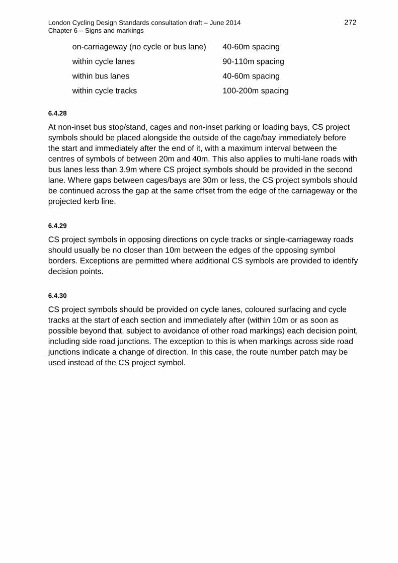
London Cycling Design Standards consultation draft – June 2014 272
Chapter 6 – Signs and markings
on-carriageway (no cycle or bus lane) 40-60m spacing
within cycle lanes 90-110m spacing
within bus lanes 40-60m spacing
within cycle tracks 100-200m spacing
6.4.28
At non-inset bus stop/stand, cages and non-inset parking or loading bays, CS project
symbols should be placed alongside the outside of the cage/bay immediately before
the start and immediately after the end of it, with a maximum interval between the
centres of symbols of between 20m and 40m. This also applies to multi-lane roads with
bus lanes less than 3.9m where CS project symbols should be provided in the second
lane. Where gaps between cages/bays are 30m or less, the CS project symbols should
be continued across the gap at the same offset from the edge of the carriageway or the
projected kerb line.
6.4.29
CS project symbols in opposing directions on cycle tracks or single-carriageway roads
should usually be no closer than 10m between the edges of the opposing symbol
borders. Exceptions are permitted where additional CS symbols are provided to identify
decision points.
6.4.30
CS project symbols should be provided on cycle lanes, coloured surfacing and cycle
tracks at the start of each section and immediately after (within 10m or as soon as
possible beyond that, subject to avoidance of other road markings) each decision point,
including side road junctions. The exception to this is when markings across side road
junctions indicate a change of direction. In this case, the route number patch may be
used instead of the CS project symbol.

London Cycling Design Standards consultation draft – June 2014 273
Chapter 6 – Signs and markings
6.5 Schedule of signs
This table is for general reference only and contains requirements current in TSRGD
(2002) rather than changes proposed in the consultation draft of TSRGD (2015), which
are described in sections 6.1-6.4 above. Please refer to TSRGD and the Traffic Signs
Manual for further details of sign application.
[612] No right turn for vehicular traffic
Normally 600mm diameter
To be illuminated
Can be used with [954.3] ‘except buses and cycles’ or [954.4]
‘except cycles’ plates (or with equivalent signs in a signal head
at 270mm diameter).
[616] No entry for vehicular traffic
Can be used with [954.4] ‘except cycles’ exemption plate
Normally 600 or 750mm diameter
To be illuminated
300mm variant (non-illuminated) can show no-entry for cycles at
one-way off-carriageway cycle tracks, but this requires site-
specific authorisation.
Authorisation of use of [954.4] ‘except cyclists’ plate was made
through the Traffic Signs (Amendment) (No.2) Regulations and
General Directions 2011 (SI 2011 No. 3041), and included in
Signing The Way (2011)
Use of [616] with [954.3] ‘except buses and cycles’ plate is
anticipated in the revised TSRGD but in the meantime requires
DfT authorisation.
[617] All vehicles are prohibited except non-
mechanically propelled vehicles being pushed by
pedestrians
Normal size 600mm
To be illuminated
Not be used on cycle routes as it would exclude
cycles.
[618] Play Street exemption plate prohibits all
vehicles from the street during the period indicated,
except for access.

London Cycling Design Standards consultation draft – June 2014 274
Chapter 6 – Signs and markings
[619] No motor vehicles (i.e. cycles permitted)
Normal size 600mm (also 450, 750, 900 and 1200mm)
To be illuminated
Can have exemption plates [620] ‘Except for access’ and [620.1]
‘Except for loading by goods vehicles’ attached.
For other permitted variants see TSRGD Direction 21 (1). A [967]
cycle route sign can be used with this sign to emphasise cycle
only access.
[877 - variation] Appropriate traffic lanes for different
movements at a junction ahead
(Extension of permitted variants to include ‘Except cycles’ or
‘Except buses and cycles’)
Normal size 900mm height (also 1200, 1500 and 1800mm)
To be illuminated
Approved for TLRN and Cycle Superhighways only. All other
uses subject to site-specific authorisation.
[881] Start of Homezone / [882] End of designated Homezone
Normal size 540mm width (also 675mm)
To be illuminated
The plate on [881] contains the name of the Homezone. This may
occupy two lines.
[950] Cycle route ahead
Can be used with [950.1] exemption plate stating ‘Cycles
crossing’, ‘Cycle event’, ‘Child cycle tests’ or ‘Child cycle training’
Normal size 600mm (also 750, 900, 1200 and 1500mm)
Direct illumination not normally required unless the sign is on a
principal or trunk road (See Schedule 17 of TSRGD) in which
case the sign should be illuminated if placed within 50m of a
system of street lighting.
[572] ‘Distance ahead to hazard’ plate or [573] ‘Distance and
direction to hazard’ may be used with this sign.
[951] Riding of pedal cycles prohibited
Normal size 270, 300mm (450 and 600mm not recommended)
Means of illumination: retroflecting material
Indicates the effect of a statutory prohibition and is placed at the
beginning of the restriction. Could be supplemented with a ‘No
cycling’ plate for which DfT authorisation is required.

London Cycling Design Standards consultation draft – June 2014 275
Chapter 6 – Signs and markings
[953] Route for use by buses and pedal cycles only
Normal size 600mm (also 450, 750 and 900mm)
Means of illumination: this sign shall have direct illumination if placed
within 50m of a lamp forming part of a system of street lighting.
Indicates the effect of a statutory prohibition and is placed at the
beginning of the restriction. Can be used in conjunction with [953.2]
‘Only’ to reinforce the meaning.
[954.3] Except buses and cycles (954.6 where used within traffic
signals)
[954.4] Except cycles
An x-height approximately one tenth of the main sign height is normally
appropriate from the prescribed options: 37.5, 50, 62.5, 75 and 100mm
37.5 is recommended for ‘Except cycles’
Means of illumination must be the same as the sign which it is placed
in combination with, unless the illumination for the sign adequately
illuminates the plate. Where either plate is used in association with
traffic light signals it must be internally/externally illuminated.
The plates indicate the effect of a statutory prohibition. They may be
used in combination with [606] or [609], ‘vehicular traffic must proceed
in the direction indicated by the arrow’. And they may be used with
[612] or [613], ‘no right/left turn for vehicular traffic’ but when such a
turn is into a contra-flow bus lane or bus/cycle only street, protected by
a [616] ‘no entry’ sign, an alternative is to use [953] ‘route for use by
buses and pedal cycles only’ or [960] ‘contra-flow bus and cycle lane’
to overcome restrictions on plates with ‘No entry’ signs.
However, [954] ‘except cycles’ may be used with [616] ‘no entry’ and
[816] ‘no through road for vehicular traffic’.
[955] Route for use by pedal cycle only
Sizes: 150mm (recommended for bollards), 270mm (recommended for
illuminated bollards), 300mm (recommended for sign posts), 450mm
(recommended for illuminated use), and 600mm (not normally
necessary)
Normally class 1 reflective material is sufficient unless the specific
location warrants direct illumination
On-carriageway, this sign indicates a Traffic Order defining a route
where only cyclists are permitted. Off-carriageway, it indicates the
effect of a statutory prohibition (erected by a Council Resolution under
the Highways Act) and is placed at the beginning of the defined
section. The 2011 TSRGD amendments changed the minimum
requirement for repeater signs to one.

London Cycling Design Standards consultation draft – June 2014 276
Chapter 6 – Signs and markings
[956] Route for use by pedal cycles and pedestrians only (i.e.
shared use)
[957] Route comprising two ways, separated by the marking
shown in diagram 1049 or 1049.1 or by physical means, for use
by pedal cycles only and by pedestrians only (separated path)
Normal size 300mm on posts. 100 and 150 may be used on
bollards and 270mm on illuminated bollards. 450mm may be
appropriate for a terminal sign that is otherwise difficult to see, eg.
against a cluttered background. 600mm is rarely warranted.
Normally class 1 reflective material is sufficient unless the specific
location warrants direct illumination. See section 7.4.
These signs indicate the effect of a statutory order (a Council
Resolution, not a Traffic Order) and are placed at the beginning of
the defined section and along a route. The 2011 TSRGD
amendments changed the minimum requirement for repeater signs
to one. For [957] symbols may be reversed in a mirror image to
represent the arrangement on the ground.
[958] With-flow bus lane ahead that bicycles, powered two-
wheelers and taxis may also use
Two sizes 800x825mm recommended (also 960x990mm)
Means of illumination is optional – internal/external lighting or
retroflecting material.
This sign indicates the effect of a statutory order. The word ‘taxi’
may be omitted and ‘local’ may be included on the bus if appropriate
(as shown below on [959] ). Permitted vehicles and times of
operations may be varied as necessary.
Use of [958.1], ‘With-flow cycle lane ahead’ is not recommended,
although there may be a case for it in situations where general
traffic is moving at 30mph or more and/or where the number of
general traffic lanes has been reduced to fit in a cycle lane.
[959] With-flow bus lane that pedal cycles may also use
Two sizes 450x825mm recommended (and 540x990mm but not
normally recommended unless speed limit is 40mph or greater)
Class 1 reflective material is normally appropriate.
This sign indicates the effect of a statutory prohibition and is placed
at intervals along the route. The word ‘taxi’ in white letters may be
added alongside the cycle symbol, and ‘local’ may be added to the
bus symbol. A powered two-wheeler may be included, as shown in
[958] above.

London Cycling Design Standards consultation draft – June 2014 277
Chapter 6 – Signs and markings
[959.1 ] With-flow cycle lane
Two sizes 375x825mm recommended (and 450x990mm)
Class 1 reflective material is normally appropriate
This sign is for mandatory lanes and is placed at intervals
along the route. Reverse may be used for offside lanes but
requires site specific authorisation
[960.1] Contra-flow (mandatory) cycle lane
Two sizes 475x825mm (recommended) and 570x990mm.
Class 1 reflective material is normally appropriate
This plate indicates the effect of a statutory prohibition, and is
placed at intervals along the route. The number of arrows
showing vehicle lanes may be varied depending on number
of lanes, normally one.
[960.2] One-way traffic with contraflow pedal cycles
Two sizes 475x650mm (recommended) and 570x780mm.
Class 1 reflective material is normally appropriate
Should be used with an advisory contraflow cycle lane, or no
lane marking.
This sign was authorised by the Traffic Signs (Amendment)
(No.2) Regulations and General Directions 2011 (SI 2011 No.
3041), having been included in Signing The Way (2011)
[961] Times of operation of a bus or cycle lane
Two sizes prescribed, 825 and 990mm
‘x-heights’ 50 and 60mm to match the size of sign used.
Method of illumination for this plate must be the same as the
sign which it is placed in combination with, unless the
illumination for the sign adequately illuminates the plate.
This sign is for mandatory lanes and is placed at intervals
along the lane, in combin-ation with [958], [958.1] or [959].
Time of day and day of the week may be varied.

London Cycling Design Standards consultation draft – June 2014 278
Chapter 6 – Signs and markings
[962.1] Cycle lane on the road at junction ahead or cycle
track crossing the road
50mm ‘x-height’ recommended
Class 1 reflective material is normally appropriate
Unlikely to be necessary and should only be used where
specific problems are encountered. [1057] cycle symbols
positioned on the cycle lane on main roads are preferred as a
method of warning emerging drivers of the likely presence of
cyclists.
Lane may be varied to track, and the cycle symbol and arrow
may be reversed for a contra-flow. If a sign is needed, and
there are lanes in both directions, the arrow should be
omitted and ‘lane’ varied to ‘lanes’. Reference to the times of
operation of the lane may be added if appropriate.
[963.1] Cycle lane with traffic proceeding from right (sign
for pedestrians)
Two sizes 40mm ‘x-height’ recommended (and 50mm)
Class 1 reflective material is recommended
This sign should not be routinely used. It is sometimes helpful
to warn pedestrians when cyclists travel from an unexpected
direction e.g. on a two-way cycle track. It will often be
sufficient to place the cycle marking to diagram 1057 in the
lane or track at the point where pedestrians cross.
‘RIGHT’ may be varied to ‘LEFT’ or ‘BOTH WAYS’, symbols
may be reversed, and ‘LANE’ may be varied to ‘TRACK’.
[966] Cyclists Rejoin Carriageway
Two sizes 40mm ‘x-height’ recommended if used (and
50mm)
Retroreflecting material is recommended
Sign has no statutory meaning. It replaced ‘Cyclists
Dismount’ as the recommended wording on this sign through
the 2011 amendments to TSRGD.

London Cycling Design Standards consultation draft – June 2014 279
Chapter 6 – Signs and markings
[967] Route recommended for pedal cycles
Two sizes 300x440mm recommended (and 375x550mm)
Retroreflecting material is recommended
The sign is for advisory cycle lanes and cycle routes on
carriageways.
959.1 should be used in conjunction with mandatory lanes.
[968/968.1] Cycle parking
170x170mm + 250x170mm recommended
(250x250mm + 420x250mm not recommended)
Retroreflective material is recommended but not a
requirement of TSRGD
This sign is usually unnecessary. It may be used in
conjunction with signing denoting a combined cycle/
motorcycle parking facility

London Cycling Design Standards consultation draft – June 2014 280
Chapter 7 – Construction
Chapter 7
Construction, including surfacing
7.1 Introduction and general issues 281
Basic construction requirements 282
Drainage 284
Construction of kerbs and segregating islands 286
7.2 Surfacing 288
Surfacing material options 288
Asphalt surfacing 291
Coloured surfacing 292
Comparison of surface materials 293
Road marking materials 294
7.3 Footways and tactile paving 296
Principles for application of tactile paving 296
Corduroy tactile paving 297
Tactiles for shared use: ladder and tramline 298
Blister tactile paving 301
Pedestrian guardrailing 301
7.4 Maintenance and asset management 302
Landscape growth 302
Surface defects 303
Maintenance of signs and markings 303
Maintenance regimes 304
7.5 Structures 305
Bridges and ramps 305
Tunnels and subways 307

London Cycling Design Standards consultation draft – June 2014 281
Chapter 7 – Construction
7.1 Introduction and general issues
7.1.1
Close attention must be paid to construction standards and details to ensure that
routes are: safe and comfortable for cyclists, attractive, legally acceptable, easy to
maintain and durable.
7.1.2
Quality of construction for cycle infrastructure is covered by the Cycling Level of
Service assessment, as shown in figure 7.1.
Figure 7.1 Key construction considerations in CLoS
Factor Indicator Relates in this chapter to...
Directness:
Directness
Deviation of route Major infrastructure such as bridges
and tunnels to make direct
connections.
Comfort:
Surface
quality
Defects: non cycle friendly
ironworks, raised/sunken
covers and gullies
Surfacing material options, drainage
design and road marking materials.
Coherence:
Wayfinding
Construction: asphalt
concrete, HRA or
blocks/bricks/setts
Attractiveness:
Greening
Green infrastructure or
sustainable materials
incorporated into design
Use of permeable surfaces as
appropriate.
7.1.3
Streetscape issues need to be considered in all aspects of design. Cycle schemes
should seek to reinforce the distinctive character of places and neighbourhoods and
wherever practical improve environmental quality by lessening the predominance of
motor traffic and traffic related street furniture. Street designers are directed to chapter
5 of this document and to the TfL Streetscape Guidance (2009) as well as other
national and individual borough’s streetscape guidance documents and streetscape-
related supplementary planning documents.
7.1.4
The sections below set out general advice to inform design development. In all cases,
the highway authority and its standard details for carriageway and footway construction
should be consulted. This is particularly important wherever the authority is expected to
adopt the facility: non-compliance with the relevant standards could lead to rejection.

London Cycling Design Standards consultation draft – June 2014 282
Chapter 7 – Construction
7.1.5
Similarly, the highway authority’s lighting unit will need to be consulted on all lighting
proposals. An appropriate level of lighting is important for all cycle routes. This may
entail upgrading existing lighting or the provision of new lighting in open spaces,
particularly where there are concerns for personal security. For aesthetic and
conservation reasons, lighting may not be acceptable through parks and other green
corridor areas. If adequate lighting is not feasible on routes away from the highway
then alternative night-time routes should be provided.
7.1.6
In some areas lighting units may be targeted and damaged by vandals, so this will
need to be taken into account in the provision. It is now possible to obtain solar
powered equipment for some installations, although this is only likely be suitable for
low-power uses.
Basic construction requirements
7.1.7
Practicalities such as cost, consideration of future maintenance and availability of
materials have a significant bearing on decisions about construction of paths, tracks
and cycle lanes. However, it is essential to remember that, from the perspective of the
user, the riding quality and reliability of the surface are the most important construction
considerations (see section 7.2 below).
7.1.8
A standard carriageway construction is appropriate for all cycling infrastructure on
carriageway. Some modifications to the surface may be required to incorporate cycle
lanes, advanced stop lines, or traffic speed control measures (traffic calming).
Dimensional tolerances should follow normal highway standards, and when a new
cycle route is installed a check should be carried out to confirm that this is the case.
7.1.9
Off-carriageway, cycle tracks and shared paths will generally have a similar
construction to footways or footpaths. Factors to consider include occasional use by
motor vehicles (eg. maintenance) and ground conditions.

London Cycling Design Standards consultation draft – June 2014 283
Chapter 7 – Construction
Typical off-carriageway facility
Diagram from Mineral Products Association, Asphalt
applications: construction and surfacing of footways and
cycleways using asphalt (2009)
7.1.10
For all types of construction, the surface is in built up in a number of layers – typically
surface course, binder course, base and sub-base. The binder, base and sub-base
should be chosen and applied in accordance with the local authority’s highway design
standards, and in a manner appropriate to the context. When considering what depth
of construction to adopt, it should be borne in mind that one of the most common
reasons why some cyclists use the main carriageway in preference to a cycle track
alongside the road is that the riding quality of the main road carriageway is better. The
riding quality of any cycle track should be at least as good as that of the adjacent road.
Further detail is provided in the guidance referred to above.
7.1.11
The depth of each layer will depend on the materials and local ground conditions –
indicatively for a cycle track, a surface course may be around 25mm, the binder and
base course may be another 50mm and the sub-base 125-225mm.
7.1.12
In all cases, consideration should also be given to:
the impact of construction and the choice of materials on drainage
responsible sourcing and re-use of construction products (bearing in mind that
certain types and colours of aggregate, for example, may not be local and will
need to be transported over a long distance)
local character, and selection of materials appropriate to the context, which may
be covered in local design or streetscape guidance
The porosity of surface, binder and base materials should be a consideration for any
integrated approach to sustainable drainage.
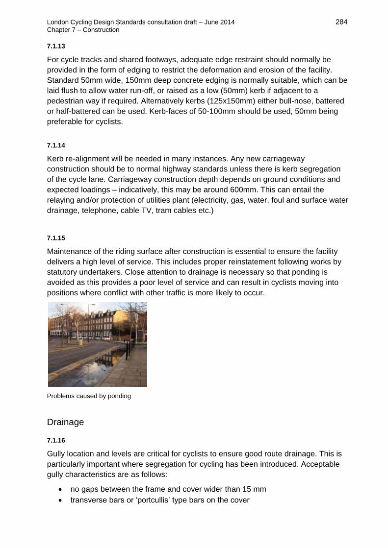
London Cycling Design Standards consultation draft – June 2014 284
Chapter 7 – Construction
7.1.13
For cycle tracks and shared footways, adequate edge restraint should normally be
provided in the form of edging to restrict the deformation and erosion of the facility.
Standard 50mm wide, 150mm deep concrete edging is normally suitable, which can be
laid flush to allow water run-off, or raised as a low (50mm) kerb if adjacent to a
pedestrian way if required. Alternatively kerbs (125x150mm) either bull-nose, battered
or half-battered can be used. Kerb-faces of 50-100mm should be used, 50mm being
preferable for cyclists.
7.1.14
Kerb re-alignment will be needed in many instances. Any new carriageway
construction should be to normal highway standards unless there is kerb segregation
of the cycle lane. Carriageway construction depth depends on ground conditions and
expected loadings – indicatively, this may be around 600mm. This can entail the
relaying and/or protection of utilities plant (electricity, gas, water, foul and surface water
drainage, telephone, cable TV, tram cables etc.)
7.1.15
Maintenance of the riding surface after construction is essential to ensure the facility
delivers a high level of service. This includes proper reinstatement following works by
statutory undertakers. Close attention to drainage is necessary so that ponding is
avoided as this provides a poor level of service and can result in cyclists moving into
positions where conflict with other traffic is more likely to occur.
Problems caused by ponding
Drainage
7.1.16
Gully location and levels are critical for cyclists to ensure good route drainage. This is
particularly important where segregation for cycling has been introduced. Acceptable
gully characteristics are as follows:
no gaps between the frame and cover wider than 15 mm
transverse bars or ‘portcullis’ type bars on the cover

London Cycling Design Standards consultation draft – June 2014 285
Chapter 7 – Construction
recessed gully frames raised to be flush (tolerance +/- 5mm) with the surface
suitable for their location to take public highway loadings
open in a manner suitable to be cleansed by a normal gulley cleansing or jetting
machine under the relevant highway authority contract
7.1.17
Dished and other gratings unsuitable for cycling across should be replaced. Side-entry
gullies or perforated kerb type gullies (such as Beany Blocks) may be suitable in some
circumstances, particularly where there is restricted width and where cyclists will be
close to the kerb. Drainage on cycle lanes and tracks may need additional gullies as
well as appropriate falls to facilitate run-off. A minimum grating size of 300 x 300mm is
recommended, as the smaller size gully gratings that are sometimes used in off-
carriageway situations tend to get blocked.
Perforated kerb gullies, as used in a cycle track
Grates should be perpendicular to direction of
travel
7.1.18
In any location where there is a possibility that cycle wheels will cross gullies, the grate
slots should be at right angles to the direction of travel. Alternatively, non-slot
‘pedestrian style’ gratings should be provided.
7.1.19
Falls of at least 1:40 cross-fall and 1:200 longitudinally are preferred. With non-
machine laid surfaces steeper longitudinal falls will be required. Falls on roads
(including ‘summit and valleying’) have often been reduced or removed during re-
surfacing, and so may need to be corrected. Any areas of ponding on a cycle route that
will have an adverse effect on cyclists should be addressed, including where splashing
from a carriageway onto an adjacent cycleway occurs.

London Cycling Design Standards consultation draft – June 2014 286
Chapter 7 – Construction
Construction of kerbs and segregating islands
7.1.20
Low kerbs (50-100mm high face) may be appropriate between cycling and pedestrian
surfaces. These can allow better use of restricted space by maximising effective width
– allowing cyclists to travel closer to them without risk of catching pedals on the kerb.
Bullnose, battered (45º faces) or half-battered kerbs can be used to help increase
effective width in this way. Red-brick and block-battered units are also available. Kerbs,
blocks and edging will normally be laid on a 150mm deep bed and haunchings in lean
concrete – refer to local authority’s standard details for construction.
7.1.21
Where they are necessary, dropped kerbs should be specified as flush, within a
tolerance of +/-6mm of the adjacent surfaces, to provide a comfortable surface for
cyclists. Where appropriate, minor upstands can be beneficial as a speed control
measure for cyclists. Particular care is needed with channel levels to ensure that
ponding does not occur at crossing points.
Typical kerb profiles
Battered kerbs as used in London, left and the Netherlands, right
7.1.22
The edges of cycle tracks and segregated lanes need to be detailed so as to provide
clear but safe delineation between carriageways and footways. Depending on width
and on context (particularly in conservation areas), suitable materials for the edge strip
or segregating island may include: paving slabs, block paving, granite setts, or
coloured surfacing.
London Cycling Design Standards consultation draft – June 2014 287
Chapter 7 – Construction
7.1.23
A strip or island installed to create segregated cycling facilities may also incorporate
parking bays, lighting columns and other street furniture. Features such as low walls
and planting may be appropriate to either protect the cycling area or improve the
ambience. Guard railing and crash-barriers can create dangerous squeeze points,
particularly where heavy goods vehicles turn, so they should be used only with caution,
and with consideration for impact on cycling provision on-carriageway.
7.1.24
The segregating strip should be visually differentiated from the cycle lane or track by
using a contrasting material. Paved strips with granite kerbs may be appropriate in
more central urban settings but grass verges may also be suitable. They are relatively
easy to maintain and provide suitable space in which to take avoiding action in case of
an emergency. Any planting should be designed with consideration of safe and
effective operation of the cycling facility. Plant height and growth, for example, should
not affect forward visibility, and thorny bushes should be avoided adjacent to the edge
of the cycling facility.

London Cycling Design Standards consultation draft – June 2014 288
Chapter 7 – Construction
7.2 Surfacing
7.2.1
Good surface riding quality is essential for cyclist safety and comfort. This is the case
whether cycling is on- or off-carriageway. Cyclists need a smooth riding surface, which
should not be undulating and should have skid resistance appropriate to the location.
The surface should be laid on adequate, well compacted base materials so that
subsequent settlement does not occur.
Sudden changes of level or ‘steps’ should be avoided, and inspection covers
and transitions between on and off-carriageway should be flush.
Potholes, rutting and other surface defects should be rectified.
Patching or re-surfacing, and deeper trench reinstatements should be carried
out as necessary.
Where anti-skid surfacing is used, it should continue over ironwork particularly
where cyclists are likely to be changing direction.
Bituminous surfaces should be well laid, usually by machine, with a finish to highway
standards and including vertical tolerances no less stringent than applicable to
carriageways.
Surfacing material options
7.2.2
This section sets out the most common materials that are used to create a good quality
surface for cycling, whether on carriageway, on a dedicated track or on a shared use
path – see figure 7.2 below.
Figure 7.2 Surface construction options
Surfacing material
Asphalt surfacing: asphalt concrete,
hot-rolled asphalt, or thin surface
course system
Generally recommended for cycling – see
section below.
Concrete Historically used on estate roads, good for
cycling if the joints and slabs are in good
condition, but surface markings are not clearly
visible.
Brick or block paving Acceptable for cycling on, but skid resistance
can be low on some brick paving types. Can be
beneficial where high cycling speeds are not
appropriate.

London Cycling Design Standards consultation draft – June 2014 289
Chapter 7 – Construction
Natural stone blocks May be suitable if bedded on mortar/concrete
and surface is not uneven or smooth, and has
good skid resistance.
Granite setts Too rough for some bikes, but if laid flush can be
acceptable in limited areas. Can polish with use
and be slippery when wet.
Surface-applied treatments
Self-binding surfaces, e.g.
limestone fines to dust, Coxwell
gravel (which has a reddish colour)
and hoggin (a well-graded mixture
of sand, gravel and clay)
Often used for rural paths, but poor skid
resistance and not very durable. Requires a
100mm aggregate base. It remains loose-ish
and dusty and is suitable only for lightly
trafficked, environmentally sensitive areas or
anywhere where a bound surface would not be
acceptable.
High-friction surfacing (anti-skid),
cold applied
Normally acceptable for cycling but laying
methods resulting in ridges should be avoided
(ie. lay in longitudinal rips rather than
transversely)
Coloured veneer coat Specialist coloured surfaces in blue, green, red
etc. laid on to wearing courses, normally anti-
skid
Resin-bonded or tar spray and chip
dressing
Often used to change the colour or grip of an
existing asphalt surface. Has the appearance of
loose gravel but the aggregate held firmly in
place. It only works on surfaces that are already
well constructed and in good condition. Loose
aggregate must be swept from the path before
use.
Surface dressing – resin-bound pea
shingle (6-8mm stone)
A cheap maintenance layer, suitable for
rural/park situations, lower skid resistance,
traditionally used on country roads.
Surface dressing – granite stone A cheap maintenance layer, acceptable for
cycling if the stone size is not too large (10-
14mm).
Slurry sealing A cheap maintenance layer, suitable for
temporary cycling use only
7.2.3
Types to be avoided for general cycling use include:
paving slabs/flags – lower wet skid resistance and risks of trips and rocking
cobbles (pebbles in concrete). – uncomfortable surface with poor skid resistance

London Cycling Design Standards consultation draft – June 2014 290
Chapter 7 – Construction
ungraded aggregate such as shingle, ballast or scalping – poorly graded
materials will be too rough and bike wheels will sink in.
Pea shingle paths in Kingston: Skerne Walk (left) and Thames Path (right)
7.2.4
Self-binding surfaces and surface dressings can be used in some circumstances,
generally away from the highway, but sealed surfaces (using bitumen or other polymer-
bound materials) should normally be chosen for cycling infrastructure. Sealed surfaces
tend to more expensive to construct but last longer, so the level of service is
significantly better and whole-life costs are usually much lower. See Sustrans, Cycle
path surface options, technical information note no.8 (2012).
.
7.2.5
For routes across parks or commons, bitumen or polymer-bound materials are
preferred, such as pea shingle surface dressing, to ensure that a smooth and durable
surface is provided. In these conditions it may be appropriate to omit formal concrete or
timber edging and allow the edge to gradually deteriorate and become overgrown by
grass. This will result in a loss of edge width of up to 300mm. Alternatively, treated
timber edge restraints may help maintain the durability of the path and sub-base but
still be sympathetic to the environment.
7.2.6
Unbound surfacing such as gravel or hoggin is only recommended for lower usage
recreational routes, due to problems with deterioration of the surface caused by
weather and use by traffic. These surfaces will also result in more road grime on
cycles. Routes likely to be used by commuters and utility cyclists should always be
hard surfaced.

London Cycling Design Standards consultation draft – June 2014 291
Chapter 7 – Construction
Asphalt surfacing
7.2.7
The typical choice for the carriageway, and for many footways, is an asphalt surface.
Asphalt used for roads and paths contain bitumens and aggregates which give a
durable, joint-free surface that is relatively straightforward to construct and maintain.
Different products are available, each with their own properties. The main variables are
the aggregate size, aggregate content, binder content and binder grade, which have an
effect on stiffness, resistance to cracking and other physical properties of the asphalt.
The smoothness of the riding surface tends to be dictated by the texture depth of the
asphalt – the higher the texture depth, the rougher the surface and vice-versa.
7.2.8
Asphalt surface treatments for carriageways, cycle tracks and footways generally come
in one of three forms:
Asphalt concrete (also known as bitmac or dense bitumen macadam)
A close-graded, 6mm asphalt concrete is typically used on footways and cycle tracks
as it gives a consistent and smooth surface finish. Designers should also consider
porous asphalt concretes where sustainable urban drainage is of benefit to the area.
HRA, hot-rolled asphalt, (with or without pre-coated chippings)
This was the UK surface material of choice before the 2000s. Its use has been in
decline especially in urban areas due to the positive textured nature of this material,
which means it generates more noise than some other treatments. For HRA with pre-
coated chippings, hard-stone (often granite) chippings are rolled into the asphalt
surface course while it is still hot. They add texture to the surface and therefore
increase its skid-resistance properties. The chippings are pre-coated with a binder,
which can contain coloured pigment if necessary. They must be hard-wearing but with
a high polished stone value (PSV), so that they are durable and do not polish over
time. A typical choice for carriageway surfaces would be HRA 35/14 but other
carriageway and footway grades exist.
TSCS, a thin surface coarse system
This is often applied to carriageway rather than footway surfaces. It typically uses a
10mm or 14mm aggregate. The advantage of using TSCS is that these materials come
in a variety of texture depths and also colours. The use of clear bitumens and coloured
aggregates allows these materials to be used as decorative asphalts. Use of such
decorative asphalts is not recommended in areas of load unless assurances are
sought from material suppliers. Note that proprietary types of TSCS have replaced
generic stone mastic asphalt (SMA).
7.2.9
The use of all these materials is described in the European Standard Specification
EN13108 and thicknesses should be specified using the British Standard BS594987:

London Cycling Design Standards consultation draft – June 2014 292
Chapter 7 – Construction
2010, Asphalts for roads and other paved areas – specification for transport, laying
compaction and type testing protocols, in conjunction with the local highway authority’s
design and construction standards. Full guidance on using the British Standards is
provided in PD 6691 Guidance on the use of BS EN 13108 Bituminous Mixtures -
material specifications (BSI, 2010).
7.2.10
In selecting a suitable type of asphalt for a given location, consideration should be
given to the wider approach to sustainable drainage – specifically the extent to which
the surface material may contribute to run-off into gullies and drains, or may be
capable of holding water in situ during a rainfall event and allowing it to permeate
slowly into the ground or on highway drainage systems. Open-graded asphalt concrete
(where finer particles are eliminated from the aggregate mix) is more porous, and may
therefore be more suitable as part of a SUDS-led approach, but its ability to hold water
reduces after application because of accumulation of dust and other particles. It can be
cleaned using a high-pressure washing, but it is difficult to reinstate its original
appearance. Any porous surface material can be laid on a porous base or installed as
part of the highway drainage.
Coloured surfacing
7.2.11
In most situations black bituminous surfacing in conjunction with cycle symbols and
appropriate lane markings is satisfactory. This should be the norm except in locations
of potential conflict where colour may be considered, such as ASL boxes and feeder
lanes (see sections 4.3 and 6.4). For some shared use facilities a different surface
treatment may also be beneficial in distinguishing these areas from dedicated cycle
facilities though this is usually best achieved by using different materials.
7.2.12
The colour of asphalt surfaces depends largely on the colour of the aggregate used.
This can be emphasised by using a clear binder – often a synthetic or vegetable-based
binder. Coloured pigment can also be added but the colour of the aggregate endures
much longer than any added colour, which tends to fade over time as the bitumen is
worn from the riding surface. Coloured aggregate may cost up to twice as much as the
standard shades of black/grey.
7.2.13
In conservation or other sensitive areas, natural stone-coloured chippings on HRA or
natural stone-coloured asphalt concrete can be used. These colours can have longer
life and better colour retention than other colours, but are often less visible.

London Cycling Design Standards consultation draft – June 2014 293
Chapter 7 – Construction
7.2.14
In London it is generally agreed that where colour is used for marking cycling facilities,
it should be Deep Chrome Green (No 267 BS381C: 1988) or blue on Cycle
Superhighways (RAL5075).
Comparison of surface materials
7.2.15
Among the most important considerations in choosing an appropriate surface material
are cost (and variation by colour), durability and skid resistance. Polished stone value
(PSV) gives a measure of skid resistance. A PSV of 55 is normally acceptable for road
skid resistance. Figure 7.3 below shows, indicatively, a comparison of different surface
materials and treatments according to these criteria. Only materials costs are included
here. Laying costs can vary considerably depending on the area (m2) and the required
traffic management arrangements – difficult and restricted access, in particular, are
likely to increase costs. The cost per square metre will also be higher for smaller areas.
In each case, more accurate figures should be obtained from suppliers.
Figure 7.3 Surface treatments and indicative costs
Surface Material Life
(years)
Skid
resistance
(PSV)
Indicative cost per square metre
(£)
Normal Red Blue/Green
6mm asphalt concrete 20 60+ 8 12 25
Coloured TSCS, 30-50mm
thick 20 55+ - 25+ 25+
Block paving 20 55 20-30 20-30 -
Brick paving 20 - - 20-40 -
Concrete paving flags 10 - 20-30 - -
Tactile paving 10 - 30-40 - -
York stone flags 20 - 160 - -
Granite paving flags 20 - 100 - -
Thermoplastic High-Friction
Surfacing 4-6 70+ 13 16 16
Resin High-Friction
Surfacing 8-10 70+ 15 18 18
Cycle Track Veneer
(thermoplastic slurry) 5 55+ 8 8 8

London Cycling Design Standards consultation draft – June 2014 294
Chapter 7 – Construction
Surface Material Life
(years)
Skid
resistance
(PSV)
Indicative cost per square metre
(£)
Normal Red Blue/Green
Cycle Lane Veneer
(polymer binder) 10 55+ 10 12 12
Slurry Seal
(poor colour and life) 5 55
Surface Dressing – Granite
Stone
(bituminous binder)
20 60+
Surface Dressing – Granite
Stone
(clear binder colour
enhance)
20 60+
Surface Dressing – Pea
Shingle Stone 20 50
Road marking materials
7.2.16
A consistent standard of road markings is required, as described in TSRGD and the
Traffic Signs Manual, chapter 5. For cycle symbols to diagram 1057, pre-formed
markings are preferred.
7.2.17
Re-surfacing works can be an opportunity to review and address various aspects of
construction quality (falls to prevent or address ponding, gulley positions, grating types,
chamber covers) and provision for cyclists (lane widths, pinch-points, corner radii, road
markings).
7.2.18
Depending on the policy of individual highways authorities, resurfacing may be an
opportunity to re-mark red and yellow lines in the minimum width, as recommended in
the Traffic Signs Manual, chapter 5. This needs to take into account enforcement
requirements, maintenance and the need for consistency between boroughs and
across London. Narrower line markings reduce visual intrusion, save on materials, can
help to visually accentuate the width of cycle lanes or coloured surfacing, and can
reduce the risk of two-wheelers skidding on road markings in the wet.

London Cycling Design Standards consultation draft – June 2014 295
Chapter 7 – Construction
7.2.19
The possible application of raised rib markings to cycle lane markings is a measure
currently under trial. The idea would be to give an audible and vibratory warning to
motor vehicles that they have encroached into a cycling facility. TSRGD (Schedule 6,
Diagrams 1012.2 and 1012.3) describes two types of ribbed marking, used for the
edge of carriageways, one with a maximum 11mm upstand, used for motorways, and
the other with an 8mm upstand. TSRGD does not recommend applying either to a
cycle lane marking: approval would need to be sought from DfT for any proposal to do
so.
7.2.20
Road studs, or cat’s eyes, are an authorised marking, primarily a means of illuminating
other road markings. These must comply with the requirements of TSRGD (Direction
57 / 58) and may only be used in conjunction with those markings stipulated in
direction 31(5). This does not currently include diagram 1049 mandatory cycle lane
marking. Any proposal to use them on cycle lane markings would need to be raised
with DfT and trialled.

London Cycling Design Standards consultation draft – June 2014 296
Chapter 7 – Construction
7.3 Footways and tactile paving
7.3.1
The needs of pedestrians must be considered in the design of cycle facilities, in
particular the needs of mobility and visually impaired people and people with learning
difficulties. The layout of pedestrian facilities should be as simple and logical as
possible and be consistent along a route.
7.3.2
Advice on tactile paving – provision of surface textures to assist blind and partially
sighted pedestrians – can be found in DfT’s Guidance on the use of Tactile Paving
Surfaces (2007). The following documents also provide useful guidance on general
issues and those specifically related to integration with cycling facilities.
CABE, Sight Line (2010)
RNIB, Building Sight (1995)
Joint Committee on Mobility of Blind and Partially Sighted People (JCMBPS), Adjacent
Facilities for Pedestrians and Cyclists (2004)
DfT, TAL 4/90 Tactile markings for segregated shared use by cyclists and pedestrians
(1990)
7.3.3
Types of tactile paving likely to be used in the construction of cycle facilities and
covered in this section include:
‘corduroy’ paving to warn pedestrians of hazards, such as shared surfaces
longitudinal ribbed ‘tramline’ paving to show cycle only surfaces adjacent to
paths
transverse ribbed ‘ladder’ paving to show pedestrian only areas
12-20mm high raised tactile marking (diagram 1049.1) to delineate cycling from
walking surfaces
blister paving adjacent to areas where pedestrians cross at controlled and
uncontrolled crossings
Principles for application of tactile paving
7.3.4
It should be noted that there is variation in practice between highway authorities, so
specific authority practice agreements will need to be taken into account. However, in
principle, consideration for users should be paramount and this means that guidance
should not be applied in an overly rigid manner.

London Cycling Design Standards consultation draft – June 2014 297
Chapter 7 – Construction
Design should be as supportive as it can be for all users, while avoiding over-
complication, illegibility or confusion. National guidance on tactile paving needs to be
interpreted in an intelligent and balanced way, informed by a good understanding of the
purpose of all the elements in any context and of the messages that need to be
conveyed to different users.
7.3.5
Signage and tactile paving can never redeem poor design. In all cases, consideration
needs to be given to the message they communicate to the intended user. In urban
areas where junctions are numerous and movements are complex, it is important to
understand what the main pedestrian and cyclist desire lines are and to use tactile
paving to clearly alert mobility and visually impaired people to the greater risk.
7.3.6
Tactile paving should be provided so that all users can detect it and therefore needs to
be no deeper than the length of the longest likely stride. Research undertaken in 2010
by University College London concluded that ‘the blister profile is readily detectable
when it is 800mm wide’, leading TfL to make a recommendation (in Streetscape
Guidance design best practice note D4, 2012) that the minimum width for longitudinal
blister tactile paving on TLRN should be reduced from the 1200mm recommended in
national guidance to 800mm.
7.3.7
On the basis that the same principle applies to other types of tactile paving, it is
reasonable to assume where tactile paving is intended to be understood only by
pedestrians, the minimum depth should be 800mm, ie. two rows of 400x400mm flags.
7.3.8
Seeking to rationalise the amount of tactile paving used in a scheme makes sense
from the perspective of legibility and comfort. Moving across certain types of tactile
paving can be uncomfortable for both pedestrians and cyclists and therefore they
should, ideally, be used sparingly.
Corduroy tactile paving
7.3.9
According to Guidance on the use of Tactile Paving Surfaces, ‘The purpose of the
corduroy surface is to warn visually impaired people of the presence of specific
hazards: steps, level crossings or the approach to on-street light rapid transit (LRT)
platforms. It is also used where a footway joins a shared route. It conveys the message
“hazard, proceed with caution”.’

London Cycling Design Standards consultation draft – June 2014 298
Chapter 7 – Construction
7.3.10
This national guidance should be consulted for
details of how and where corduroy tactile paving
should be used. In most instances where cycling
and pedestrian facilities at footway level are
separated, ladder and tramline tactile should be
used to show a transition between separated
facilities and a shared use area. Corduroy tactile is
only likely to be necessary where another footpath
(pedestrian use only) joins a shared area.
7.3.11
Corduroy tactile paving material has ribs that are rounded at the top and spaced closer
together (50mm apart) than ladder and tramline tactile paving. It should be
accompanied by a shared use sign to diagram 956. Buff, grey or charcoal colour tactile
paving is available to match the footway. The depth of 1200mm recommended in
Guidance on the use of Tactile Paving Surfaces may be reduced to 800mm in most
instances for reasons described above.
7.3.12
Corduroy tactile paving material has also developed a
‘variant’ use (ie one not described in DfT guidance) as
substituting for a kerb edge in schemes where a level
surface treatment has been applied. This is in order
help blind and partially sighted pedestrians find the
edge and is intended particularly to assist cane users.
Whether this treatment is appropriate will depend on
the overall design for a street. It should not be applied
without broader consideration of the needs of all
users as part of a scheme and without assurances
from user groups that it will convey the intended
message.
Corduroy paving used instead of a
kerb edge at Bexleyheath
Tactiles for shared use: ladder and tramline
7.3.13
Guidance on the use of Tactile Paving Surfaces and Traffic Advisory Leaflet TAL 4/90
recommend that corduroy and ladder-and-tramline tactile paving should be applied to
shared use areas to allow people, particularly visually impaired users, to detect a
transition between a shared area and separate spaces for pedestrian and cycle
movement. On the cycling side, the ‘tramline’ tactile is aligned with the direction of
movement. On the pedestrian side, it is laid transversely in a ‘ladder pattern’ – that is

London Cycling Design Standards consultation draft – June 2014 299
Chapter 7 – Construction
across the direction of movement. Raised profiled delineator markings (TSRGD
diagram 1049.1) are used to divide the surface.
7.3.14
Ladder and tramline tactile paving material ribs are wider and flat across the top, and
they are spaced further apart (70mm) than on corduroy type tactile paving. The profiled
slabs are available in the normal modular paving size of 400 x 400mm in various
colours. These include light or dark grey, buff, or green, so that a consistent colour
background can be achieved and also to allow painted markings such as give way or
cycle logos to be more visible.
7.3.15
It is possible to use tramline tactile paving on its own at the start of a cycle track and
accompanied by cycle track sign TSRGD diagram 955, or at the start of a segregated
path with sign diagram 957. However, it is preferable that other visual cues should be
used to identify a facility as a track or path for cyclists before resorting to tactile paving.
7.3.16
A proportionate approach needs to be taken to applying these tactiles, bearing in mind
the message that needs to be conveyed. For example, where ladder-and-tramline
tactile paving indicates a transition from separated to shared provision, then the key
recipients of the message are cyclists. Entering a shared area means, for them, that
they are more likely to encounter pedestrians and that there is a much greater
obligation to act with courtesy and give way to pedestrians, modifying their speed as
necessary.
7.3.17
For pedestrians, understanding the message about the shared area, or knowing that
they have passed from a dedicated pedestrian space into a shared area, is less crucial
because a change in behaviour is not necessarily required from them. It is important,
however, that they understand when they are stepping into an area for cycling, so this
should be distinguished from the footway using a raised delineator strip and tramline
tactile paving.
7.3.18
Certain other difficulties arise in instances where guidance suggests that tactile paving
is required in order to sign a transition from separated to shared space.
It is more or less impossible to account for every direction or angle of possible
pedestrian movement – this makes it difficult to provide tactile paving that is fit-
for-purpose.

London Cycling Design Standards consultation draft – June 2014 300
Chapter 7 – Construction
Cyclists can slip on tramline tactile paving, particularly in wet or freezing
conditions – their wheels can become deflected by the longitudinal grooves.
It is recommended that all other alternatives should be explored before relying
on tactile paving to distinguish between different areas. Preferably, this should
include clear physical and/or visual dinstinction between an area for cycling and
a shared area.
7.3.19
Rather than the depth of 2400mm stipulated in Guidance on the use of Tactile Paving
Surfaces, it is recommended that 1200mm should be the minimum depth for ladder
and tramline tactiles at the beginning of and end of a separated facility and that 800mm
should be required at more minor, repeated transitions along the way. In some cases
the ‘ladder’ paving on the pedestrian side could be omitted to avoid confusion, where
there are extensive areas of different tactile paving types.
Where appropriate, 2400mm depth of ladder and tramline may be reduced to 1200mm.
7.3.20
Where guidance indicates that both blister and ribbed tactiles are required, the ribbed
paving will normally need to be set back from the kerb-line by 2-3m to avoid confusing
blind people when they have crossed a carriageway. This will allow them to reach the
comparative safety of a (shared) footway before having to determine on which side of
the shared surface to proceed.
7.3.21
Where a cycling scheme appears to require a large amount of corduroy and ladder-
and-tramline, this usually indicates that the design solution is not fit-for-purpose and it
should prompt a re-design.
If cyclists cannot be accommodated in safety and comfort on the carriageway, or
vertically separated from pedestrians off-carriageway, then fully shared use may very
often preferable to short, ‘stop-start’ sections of separated use at footway level.
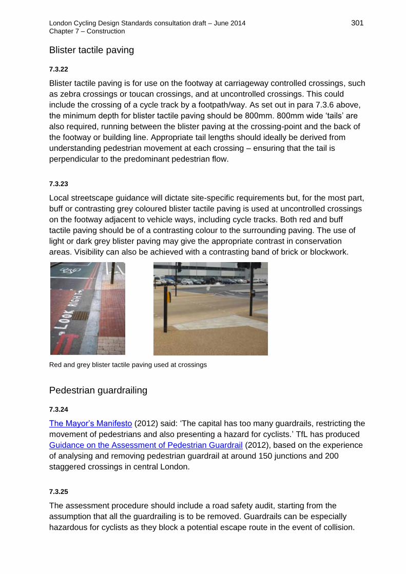
London Cycling Design Standards consultation draft – June 2014 301
Chapter 7 – Construction
Blister tactile paving
7.3.22
Blister tactile paving is for use on the footway at carriageway controlled crossings, such
as zebra crossings or toucan crossings, and at uncontrolled crossings. This could
include the crossing of a cycle track by a footpath/way. As set out in para 7.3.6 above,
the minimum depth for blister tactile paving should be 800mm. 800mm wide ‘tails’ are
also required, running between the blister paving at the crossing-point and the back of
the footway or building line. Appropriate tail lengths should ideally be derived from
understanding pedestrian movement at each crossing – ensuring that the tail is
perpendicular to the predominant pedestrian flow.
7.3.23
Local streetscape guidance will dictate site-specific requirements but, for the most part,
buff or contrasting grey coloured blister tactile paving is used at uncontrolled crossings
on the footway adjacent to vehicle ways, including cycle tracks. Both red and buff
tactile paving should be of a contrasting colour to the surrounding paving. The use of
light or dark grey blister paving may give the appropriate contrast in conservation
areas. Visibility can also be achieved with a contrasting band of brick or blockwork.
Red and grey blister tactile paving used at crossings
Pedestrian guardrailing
7.3.24
The Mayor’s Manifesto (2012) said: ‘The capital has too many guardrails, restricting the
movement of pedestrians and also presenting a hazard for cyclists.’ TfL has produced
Guidance on the Assessment of Pedestrian Guardrail (2012), based on the experience
of analysing and removing pedestrian guardrail at around 150 junctions and 200
staggered crossings in central London.
7.3.25
The assessment procedure should include a road safety audit, starting from the
assumption that all the guardrailing is to be removed. Guardrails can be especially
hazardous for cyclists as they block a potential escape route in the event of collision.

London Cycling Design Standards consultation draft – June 2014 302
Chapter 7 – Construction
7.4 Maintenance and asset management
7.4.1
The maintenance of cycle routes and cycle facilities is essential if they are to
encourage cycle use. Most of the conditions covered in this section have a greater
negative impact on cyclists as compared to motorists, and frequently result in severe
hazards for cyclists. Cycle route infrastructure design should include access for the use
of maintenance vehicles where appropriate, particularly where the route is off-
carriageway.
Sweeping
7.4.2
Appropriate frequencies for sweeping are important and these may only become
apparent after a route has opened. Broken glass or other debris often blown across by
motor traffic is the most frequent problem. This can cause danger to cyclists trying to
avoid it, or inconvenience to detour via an alternative route, or to mend a puncture.
7.4.3
Debris can be a particular problem when cycle lanes are introduced so that debris
ceases to be deflected by the normal flow of vehicles. Any changes to the cleansing
contractor’s schedule will need to be notified and agreed, and should be recorded in
case cleansing problems arise.
Landscape growth
7.4.4
Cycle tracks, adjacent paths and shared paths
frequently suffer from problems from the growth of
adjacent planting. This can seriously reduce the
available width of a path, and reduce sight lines to
create blind spots, sometimes giving rise to social
safety issues. Cyclists can find it harder than
pedestrians to avoid branches due to their speed, and
their height off the ground, especially when on a
bicycle.
Consider proximity of trees and
bushes when planning and
maintaining signs
7.4.5
Trimmed-back thorn bushes need to be thoroughly removed after cutting to ensure that
punctures do not result. Preferably separate cycle tracks from thorn bushes.

London Cycling Design Standards consultation draft – June 2014 303
Chapter 7 – Construction
7.4.6
In summer, many cyclists, especially children, will be wearing shorts. Stinging nettles
and brambles can grow quickly so frequent maintenance is required.
Surface defects
7.4.7
Uneven surfaces can affect the balance and stability of bikes, or generate swerving
manoeuvres, and can cause the rider discomfort. Potholes, bumps, ridges, and sunken
gully and inspection cover gratings are frequent problems that should be addressed.
Steps in excess of 10mm or deformation in excess of 10mm over a 1m straight edge
length should be rectified.
7.4.8
Ironwork such as manhole covers should be checked during routine inspections so that
skid resistance is compatible with that of the surrounding road surface, particularly
where surface coatings have been applied.
7.4.9
Blocked drainage gullies or inadequate drainage are frequent problems on cycle
routes, and should be identified and rectified during normal maintenance routines. Any
additional drainage will need to be included within the drainage maintenance schedule
in conjunction with other asset management.
Maintenance of signs and markings
7.4.10
Clear signs and markings are important both for safety reasons and the legibility and
coherence of routes. Signs can be rotated, removed unofficially, not replaced after
collision damage, and can be made illegible with graffiti. Problems such as these can
give the impression of a route with problems of social safety as well as indicating lack
of importance given to cycling by the managing authority.
Anti-rotational brackets should be fitted to appropriate signs, particularly ‘finger’
direction signposts – see section 6.3.
Surface markings are likely to become worn, and may be removed by trench
digging or by resurfacing. These defects should be rectified as soon as they
become illegible.
7.4.11
Where significant lengths of re-surfacing requires the removal of existing red or yellow
line markings, highways authorities should consider providing replacement lines at the
minimum permitted width. In addition to reducing visual intrusion and saving on

London Cycling Design Standards consultation draft – June 2014 304
Chapter 7 – Construction
materials, this can help to visually accentuate the width of cycle lanes or coloured
surfacing and reduce the risk of cyclists skidding on road markings in the wet. The
Traffic Signs Manual, chapter 5 allows for this. 50mm line width is technically
acceptable for design speeds of up to 30mph, and 100mm above this. Design teams
should take account both of enforcement requirements and reasonable consistency of
appearance.
Maintenance regimes
7.4.12
Cyclists’ needs should be taken into account in risk registers and maintenance
regimes. On carriageway, defects in certain locations may not cause problems for
motor vehicles, but could cause significant risks for cyclists. Off carriageway, there is
often a poor understanding of cyclists’ needs on cycle tracks and shared use footways.
7.4.13
The quality, comfort and popularity of designated cycle routes depend on the surface
continuing to be of consistently high quality. A regime is required to ensure that defects
are picked up and acted on as soon as possible. Visual inspection by bicycle and on
foot are the simplest ways to do this but cycle or motor vehicle mounted equipment can
be a useful additional tool in measuring surface quality on a regular basis.
7.4.14
TfL has developed the following simply hierarchy based on cycle flows and the relative
importance of designated routes:
Prestige
Policy priority route, with very high flows (>2500 cyclists/day) and/or part of the Cycle
Superhighway network.
Primary
High flows (1000 to 2500 cyclists/day) and/or sites that are part of designated cycling
routes.
Secondary
Medium / low flows (≤1000 cyclists/day) and/or local access and links, as shown on the
TfL cycle guide maps.
Cyclists excluded
Any section of Highway at which cyclists are legally excluded.

London Cycling Design Standards consultation draft – June 2014 305
Chapter 7 – Construction
7.5 Structures
7.5.1
Making difficult connections can often only be done by taking cycling facilities over or
under other features such as highways, railways and waterways. Because these
require cyclists to deal with gradients, and because they are likely to be costly, a strong
case will need to be made for their construction: comparison with other reasonable
options and a strong benefit-to-cost ratio, for example. However, bridges and subways
can play an important role in cycling networks, and they can offer a high degree of
safety and directness.
7.5.2
Advice on structures in this section is generally to be found in the Design Manual for
Roads and Bridges (DMRB). Individual sections are referenced in the text below.
Bridges and ramps
White House Lane bridge, Hackney – before and after. Conversion to a fit-for-purpose cycling link.
7.5.3
New bridges should allow for comfortable and direct cycle and pedestrian movement
and, wherever practicable, some separation should be provided. Consideration should
be given to the probable growth in both cyclist and pedestrian numbers from making a
new link. New pedestrian/cycle bridges in urban areas should be built with at least 4m
clear width.
7.5.4
Bridges for cyclists’ use should be designed so as not to require cyclists to dismount
and use steps. Access ramps are the best ways of meeting cyclists’ needs. Ramps
should preferably avoid 90- or 180-degree turns, and have a gradient shallow enough
to allow most cyclists to continue to ride up the slope. This should be no greater than
1:20, although as steep as 1:12 may be acceptable in some circumstances.

London Cycling Design Standards consultation draft – June 2014 306
Chapter 7 – Construction
Bridges with separate pedestrian and cycling facilities in Stockholm (left) and Minneapolis (right)
Ravensbury Park shared use bridge, Merton
Access ramp, Richmond
7.5.5
Where steps are unavoidable at bridges and subways, or as a short term low cost
measure pending replacement, concrete or steel-section wheeling ramps should be
installed. They should be at least 100mm and 50mm deep and can be on one or both
sides, at least 0.2m away from the wall and/or banister. Retrofitting wheeling ramps
should be considered whenever bridges, railway stations and underpasses are
refurbished. Care needs to be taken to avoid compromising the accessibility needs of
pedestrians, particularly young children, the elderly and mobility impaired users,
through installing such a ramp. Where this is an issue, a ramp on one side only may be
the best solution.
Wheeling ramps

London Cycling Design Standards consultation draft – June 2014 307
Chapter 7 – Construction
7.5.6
The minimum vertical headroom provided for cyclists should be 2.3m (as opposed to
2.1m for pedestrians) to allow for cyclists’ higher position when riding. This will also
apply to all signs that may obstruct cyclists.
7.5.7
On footbridges intended for shared pedestrian and
cycle use the minimum parapet height stipulated by
DMRB, section BD 29/04 is 1.4m. Where
pedestrian and cycle use is separated, this
requirement only applies to the cycle side. On other
structures and situations it is recommended that a
risk assessment be carried out to inform design
options. The Sustrans guide, Parapet heights on
cycle routes: Technical information note no. 30
(2012), includes guidance on undertaking such a
risk assessment.
High bridge parapets
Tunnels and subways
7.5.8
A dedicated cycle tunnel or subway, or one shared with pedestrians, may be a viable
option as part of an urban cycling network. It can help:
avoid circuituous, possibly motor traffic-dominated routes
give protection from weather and, provided it is not used by other vehicles, a
good riding surface
offer consistent provision where the tracks join off-carriageway facilities on
either side
7.5.9
A well designed tunnel or subway could become an attractive, distinctive and
memorable part of any cycling route. However, this will require good lighting, high
standards of maintenance and comfortable ways of getting on an off the facility (ie.
ramps), so construction and maintenance costs are likely to be high.
7.5.10
DMRB section BD 78/99 sets out tunnel design requirements for vehicular traffic, much
of which also applies to tunnels for cycle and/or pedestrian use only. The DMRB
definition of a road tunnel is ‘a subsurface highway structure enclosed for a length of
150m, or more’. Most of the basic design and management requirements set out in
DMRB are assumed to apply to tunnels largely dedicated to cycling.

London Cycling Design Standards consultation draft – June 2014 308
Chapter 7 – Construction
7.5.11
Headroom through subways should be a minimum of 2.4m (DMRB, section TD 36/93).
If this cannot be achieved because of structural constraints, then the reduced
headroom should be highlighted using an explanatory sign with the text ‘Cyclists
beware – low headroom’, and stating the actual height available.
7.5.12
Sustrans’ Technical Information Note No.29, Lighting of cycle paths (2012) provides
further information on design considerations for tunnels, underpasses, subways and
bridges.

London Cycling Design Standards: consultation draft – June 2014 Chapter 8 – Cycle parking
309
Chapter 8
Cycle parking
8.1 Why cycle parking is important 310
Policy context 311
8.2 Procedures 313
Assessing demand for cycle parking 313
Fit-for-purpose cycle parking 315
Well located cycle parking 316
Secure, well overlooked cycle parking 317
8.3 Types of cycle parking 319
Tubular stands 319
Two-tier stands 321
Cycle lockers 322
Secure shelters and compounds 323
Parking for larger bicycles 324
8.4 Cycle parking in the public realm 325
Standard practice in layout of stands 325
Integration with streetscape design 327
8.5 Cycle parking to support different uses 329
Public transport interchanges 329
Cycle parking hubs 332
Housing 333
Shops and places of work 336
Cycle parking at schools 338
Large, multi-access sites 339

London Cycling Design Standards: consultation draft – June 2014 Chapter 8 – Cycle parking
310
8.1 Why cycle parking is important
8.1.1
Provision of cycle parking and its security are essential for supporting the development
of cycling as a practical transport choice. A lack of appropriate cycle parking facilities is
often cited as a barrier to cycling and bicycle ownership.
The number and the quality of cycle parking spaces available must not only keep pace
with the growing use of bicycles in London, but also needs to allow for the substantial
future growth set out in the Mayor’s Vision for Cycling.
8.1.2
Opportunities to provide more and better cycle parking should not have to come
exclusively through programmes and projects aimed at promoting cycling. Various
streetscape and highway improvements offer the possibility of raising the quality of
cycle parking provision in the public realm.
8.1.3
Cycle parking also needs to be a key consideration for any new development that
people are expected to travel to and from – just as journeys on foot, by public transport
and by private car are planned for. Through the planning process, high quality cycle
parking should be regarded as an integral part of a scheme, an essential part of the
attraction of a development – never just an add-on to meet minimum policy
requirements.
8.1.4
This chapter focuses primarily on the quality of cycle parking and the process for
planning and implementing it. Key principles underpinning this guidance are that cycle
parking should be:
Fit-for-purpose – meeting identified current
and future demand, with an appropriate balance
of short-stay and longer-stay provision.
Well-located – convenient, accessible and as
close as possible to the destination.
Secure, visible and well-overlooked – stands
that allow for secure locking in places that are
well lit and with high levels of natural
surveillance.
Cycle parking in Covent Garden

London Cycling Design Standards: consultation draft – June 2014 Chapter 8 – Cycle parking
311
Policy context
8.1.5
Local authorities and developers are expected to make appropriate provision for cycle
parking to support ambitious targets for cycling in the Mayor’s Transport Strategy
(2010). In order to fulfil that role effectively, the quality of cycle parking will be as
important as the quantity. A number of key issues around the quality of cycle parking
were raised in the London Assembly report, Stand and Deliver: Cycle Parking in
London (2009).
8.1.6
TfL’s Cycle Security Plan (2010) aims to
tackle the issue of cycle theft by
improving the cycle parking
environment. This includes actions to
increase the number of fit-for-purpose
cycle parking spaces and to provide
advice on locating cycle parking. It also
advocates more detailed design
guidance on secure cycle parking.
8.1.7
‘We will deliver 80,000 additional cycle parking spaces in residential locations, stations,
workplaces and other trip destinations by 2016. We will put them where people most
need them, above all in central London.’ The Mayor’s Vision for Cycling, 2013, p24.
The Vision promises more cycle parking at central London termini and suburban
stations, enabling better integration between transport modes and embedding types of
travel behaviour that support trip chaining. The Vision also introduces the idea of cycle
hubs and superhubs, which will provide extensive and secure parking and are located
where cycle routes intersect. Hubs should incorporate cycle hire and other associated
facilities such as cycle repair.
8.1.8
The London Plan requires better cycle parking through planning. In the Further
Alterations to the London Plan (2014) new cycle parking standards are proposed for
new or re-development in London by use class, including specific requirements for both
long and short-stay parking. While these standards establish minima for cycle parking
provision, clients, designers and planners should seek to identify and meet identified
future demand, which will invariably lead to a higher level of provision than the
minimum standards.

London Cycling Design Standards: consultation draft – June 2014 Chapter 8 – Cycle parking
312 8.1.9
Long-stay cycle parking serving particular buildings or sites is primarily for residents or
staff, and should be provided in secure, covered facilities with controlled, step-free
access. Short-stay parking may be for visitors, customers or other short-stay needs
and should be highly visible, accessible, convenient and as close to the main site or
building entrance as possible. The guidance in this document should be used to inform
the location, type and design of the parking agreed and delivered.
8.1.10
Assessment of cycle parking provision should take into account current demand and
predicted trends for cycling across London. This should be allied with advice in this
document on achieving the best quality of provision, in terms of location, design and
type. This is important in order to:
ensure that adequate facilities are available for those who already cycle
reduce cycle theft through appropriate facilities to lock and store bikes
encourage more people to choose cycling as a mode of transport
reduce obstruction and other nuisance caused by ad-hoc ‘fly parking’
relocate any under-used cycle parking
help more children to cycle
8.1.11
In summary, the planning process should be used to help deliver better cycle parking
for London through:
applying London Plan and Local Plan policies and standards on cycle parking to
new development
ensuring that development and transport plans include proposals for addressing
existing gaps in provision
using planning obligations and conditions to help deliver additional high quality
cycle parking facilities to meet those identified gaps

London Cycling Design Standards: consultation draft – June 2014 Chapter 8 – Cycle parking
313
8.2 Procedures
8.2.1
Providing the right cycle parking for a place requires an understanding of the dynamics
of current and likely future cycle use in an area, and ideally should be planned in an
integrated way with cycle routes. Qualitative criteria are just as important as the
quantity of cycle parking provided. The section below on design principles for cycle
parking sets out key requirements.
Assessing demand for cycle parking
8.2.2
Cycle parking should be provided where there is evidence of demand and/or the
potential to attract use. Consideration should be given to the probable need for cycle
parking to serve a demand that is currently suppressed. For any strategy that aims to
increase cycling substantially in an area, increase in demand for cycle parking over and
above that suggested by analysis of trip generators should be planned for.
The right amount of cycle parking for a site or area would be at a level that:
meets existing baseline demand
meets the potential demand generated by the existing and proposed land
uses in the area
ensures there is allowance for spare capacity (ideally, at least 20 per cent)
8.2.3
All destinations should be served by cycle parking that can accommodate employees,
customers, residents and visitors. Key destinations include:
residential areas
shopping centres and high streets
workplaces
services, e.g. hospitals, health centres, council buildings
education establishments including schools, colleges and universities.
community facilities and services e.g. libraries
entertainment and leisure venues
public transport interchanges and National Rail, Docklands Light Railway and
London Underground and Overground stations

London Cycling Design Standards: consultation draft – June 2014 Chapter 8 – Cycle parking
314 8.2.4
Methods of assessing potential demand include:
surveys of existing patterns of cycle parking, taking into account formal and
informal parking areas, existing cycle stands in public and private areas, and
‘fly parking’ to street furniture and guard railing
undertaking surveys at different times of the day, week and year – cycle
parking demand in winter tends to be approximately 60-80 per cent of the
demand in summer, while identifying variations by time of day and day of
week can reveal peaks and give indications of trip purpose
making a broader assessment of where trip generators are, and where and
when people are likely to – or could – travel there by bicycle. This includes
identifying where and when new developments are proposed locally.
trialling temporary stands
Cycle parking serving destinations
Gauge demand for cycle parking
8.2.5
Provision of new or increased cycle parking should also be informed by consultation
with cyclists, pedestrians, retailers and local residents, many of whom will be able to
give a more rounded view about variation of cycle parking demand through the day,
week and year. This should be proportionate to the level of investment and the likely
impact on other users.
8.2.6
If the target London-wide mode share of around 5 per cent by 2026 is to be achieved,
certain more accessible locations will need to deliver mode shares substantially higher
than this. As TfL’s cycle census of April 2013 showed, many locations see a cycling
mode share above 20 per cent during peak hours. (TfL, Central London Cycle Census:
technical note, October 2013). Levels of cycling in central and many parts of inner
London are likely to continue to see higher-than-average increases, with investment in
better routes through the Mayor’s Vision for Cycling programme. Those significant
changes need taking into account when estimates of future mode share are made.

London Cycling Design Standards: consultation draft – June 2014 Chapter 8 – Cycle parking
315 8.2.7
For new development, applicants should consult the latest version of the London Plan
to verify minimum requirements, and should check with the local planning authority,
which may have its own minimum standards in its Local Plan. Developers and planners
should seek greater provision than the minimum wherever possible, particularly in
locations where trips by bicycle could grow substantially. The quantity and quality of
cycle parking is likely to become an ever more important factor in attracting potential
buyers, occupiers and customers.
8.2.8
The feasibility of providing cycle parking in a given location needs to be considered
alongside assessing demand. Footway space and underground utilities or structures
will determine whether locations are suitable. Clarity about these constraints is
important before consulting on any options for new cycle parking.
8.2.9
A Traffic Regulation Order (TRO) is necessary for on-carriageway cycle parking, but
not for off-carriageway (ie. on the footway), although this may be an effective form of
consultation in some sensitive areas. Obtaining a TRO involves several stages:
consultation on initial layout / design: obtaining the view of local councillors,
emergency services and other relevant institutions
advertisement of the TRO, via public notices, for at least 21 days
making the TRO
implementing the TRO
8.2.10
Alternatively, a temporary TRO may be secured more quickly for a temporary use of
part of the carriageway for cycle parking, for up to 18 months.
Fit-for-purpose cycle parking
8.2.11
In planning cycle parking, it is important to ensure that provision is appropriate for the
purpose of the trip and the length of stay. Peaks and the spread of demand across the
day need to be considered.
8.2.12
In workplaces, the demand for spaces will be at similar times during the working day.
Spaces may be assumed to be used frequently with a low turnover in the number of
people using a space in one day. In these instances the cycle parking will not

London Cycling Design Standards: consultation draft – June 2014 Chapter 8 – Cycle parking
316
necessarily need to be as visible as parking in a shopping area would need to be,
though a higher level of ‘access only’ security will be required.
8.2.13
In contrast, a Sheffield stand located in a busy shopping area is likely to offer a
convenient facility, suitable for short stays, and should be located in a highly visible
area with good natural surveillance. This parking is also likely to have a higher daily
turnover of use.
Bespoke cycle stands, Windrush Square, Brixton
Cycle stands for DLR stations
8.2.14
A fit-for-purpose stand is also one that is appropriate for its context, and alternative
types may be needed for sensitive areas. By using bespoke types, cycle parking can
also serve a place-making function as part of an integrated approach to public realm
improvement.
Well located cycle parking
8.2.15
Proximity to a destination influences a cyclist’s choice of where to park, so cycle
parking should be convenient and well located. As a general rule, cycle parking should
be provided:
as close as possible to the final destination
within 15m for short-stay parking serving a single destination
within 25m for short-stay parking serving multiple sites
within 50m for longer-stay parking
in convenient locations for entrances to and exits from the destination
where there is easy access – eg. through use of dropped kerbs, cycle routes
and crossings

London Cycling Design Standards: consultation draft – June 2014 Chapter 8 – Cycle parking
317 8.2.16
Where cycle parking is inside a building, it should located so as to avoid the need to
negotiate obstacles such as stairs, tight corners, multiple doors and narrow doorways.
Lifts should be provided to any basement cycle parking and accessing the parking area
should involve passing through no more than two sets of doors.
8.2.17
The strategy for signage and wayfinding in an area should ensure
cycle parking is easy to find, and also help cyclists continue their
journey from the parking area. TSRGD contains a standard sign,
diagram 968, for this purpose. Wherever it is necessary, any such
sign should be mounted so as to avoid creating additional sign
clutter in the public realm.
Secure, well overlooked cycle parking
8.2.18
Wherever it is located, cycle parking must be secure, visible and well overlooked.
Users need to feel both that their bicycle will be safe where it is parked, and that they
will be safe accessing and using the parking. Cycle parking should be:
sited in locations that are clearly visible and well overlooked with high levels of
natural surveillance, and CCTV where necessary
designed with consideration of sight lines into and out of the cycle storage area
– this is particularly important when cycle cages, compounds or secure stores
are provided
adequately lit and overlooked, particularly at night time or where the parking is
indoors/under cover
8.2.19
A wide range of cycle parking products is available, but the cycle parking design
chosen, and the location of the cycle parking should as far as possible:
allow the frame and both wheels of the bicycle to be secured
provide support for any type of bicycle without damaging it
ensure that, whether in use or not, the stand is not causing an obstruction or
danger to pedestrian movements, or causing the user to be in danger or a
danger to vehicles on the carriageway

London Cycling Design Standards: consultation draft – June 2014 Chapter 8 – Cycle parking
318 8.2.20
In order to allow for securing the bicycle by the
frame and both wheels, locking points should
be approximately 600mm apart and 500mm
above ground. The stand shape should provide
locking within 100mm of these points to
facilitate the use of two ‘D’ locks, i.e. range of
400-800mm in width and 400-600mm above
ground. It should be noted that stands thicker
than 75mm will stop the use of a ‘D’ lock.
Recommended double locking
practice
8.2.21
Damaged or vandalised bicycles left in public often signal the insecurity of cycle
parking and, in some areas, cycle parking facilities are unlawfully occupied by
motorcycles and scooters, sending a similar negative message.

London Cycling Design Standards: consultation draft – June 2014 Chapter 8 – Cycle parking
319
8.3 Types of cycle parking
8.3.1
The three design principles for cycle parking – fit-for-purpose, well located and secure
– should apply to the choice of cycle stand. Response to context should be addressed
through conforming to relevant street design guidance.
8.3.2
Space available is always likely to be a constraint, although the choice of cycle parking
type should not be dictated by space alone. Indicatively, types such as the Sheffield
stand offer around one space per 1.4 sq m (if implemented according to the guidance
in section 8.4 below), meaning that 1,000 spaces requires 1,400 sq m. High density
facilities, such as the two-tier stand, offer around one space per 0.7 sq m, or 1,000
spaces in 700 sq m.
Tubular stands
Sheffield stand, with
visibility bands and
tapping rail
M-profile stand
Alternative type of tubular stand
8.3.3
Sheffield stands are the most common type of tubular stand. They offer a simple,
robust and cost effective cycle parking solution: two bikes can be parked on one stand
and a range of locking positions are possible.
8.3.4
It is recommended that the finish of stands on the highway should be either stainless
steel or galvanised with a black nylon coating that is hard-wearing and does not scratch
the bicycle’s paintwork. Stands located off-highway in compounds may be plain
galvanised steel.

London Cycling Design Standards: consultation draft – June 2014 Chapter 8 – Cycle parking
320 8.3.5
Visibility bands must be used on Sheffield stands to assist partially sighted street users
to identify areas of cycle parking, and should be identifiable by using agreed
contrasting colours. For example, a black visibility band should be used on a stand with
a stainless steel finish. A tapping rail is usually required on cycle stands, or on the end
unit when stands are grouped together, so that an empty stand can be identified by a
pedestrian using a white cane.
8.3.6
An alternative to the Sheffield stand is the M-profile stand, which has been designed
specifically to facilitate double locking.
8.3.7
Other tubular cycle parking designs are available on the market, and may be suitable in
many locations. While it is important to take a flexible approach to the design of cycle
parking stands, they should always fulfil the main function of allowing for two-point
frame and wheel locking.

London Cycling Design Standards: consultation draft – June 2014 Chapter 8 – Cycle parking
321
Standard details and dimensions for Sheffield stand (above) and M-profile stand (below)
Two-tier stands
8.3.8
Two tier cycle racks are an innovative solution tackling the issues of space constraints
and high demand for cycle parking. The racking system stores bicycles above each
other, increasing the capacity of cycle parking sites. Racking systems are best
provided in locations where instructions for use can be given to ensure that cyclists use
the facilities safely.
Two-tiered, high capacity cycle parking at Liverpool Street station (left) and Euston station (right)

London Cycling Design Standards: consultation draft – June 2014 Chapter 8 – Cycle parking
322 8.3.9
A minimum aisle width of 2500mm beyond the lowered frame is required to allow
bicycles to be turned and loaded. An overall aisle width of 3500mm should be provided
in areas of two-way movements and racks on either side of aisles, though this may limit
the density advantages of two tier stands. The minimum height requirement is
2600mm.
8.3.10
Careful consideration should be given to:
the location of stands, minimising conflict with pedestrians using the surrounding
area
the level of natural surveillance surrounding the stands to ensure users feel
confident to lock their bicycles using the stand
the design of the chosen stand, to ensure bicycles can be locked by securing at
least one wheel and the frame – it is possible to specify two-tier racks with an
additional security bar, to enable both wheels and the frame to be secured
Cycle lockers
8.3.11
Cycle lockers can offer secure and dry
parking, and other storage facilities for
longer stays. However they require more
management than other cycle parking
solutions.
8.3.12
Consideration should be given to:
the design of the locker, particularly any moving parts, which are particularly
vulnerable to vandalism or leverage by thieves
the space available and cycle parking demand – some cycle lockers have a
large footprint
whether the locker is suitable for all sizes of bicycle (a typical adult bicycle is
approximately 1800mm long and 1200mm tall)
the level of supervision of locker sites, ensuring they do not suffer from
vandalism or misuse
the location of lockers within a site, to ensure the facility is convenient and
accessible

London Cycling Design Standards: consultation draft – June 2014 Chapter 8 – Cycle parking
323
the operation and management system of lockers when installed and
sustainability of any system in the future, allowing access to anyone who wants
to use it
a management system, which may be provided by the supplier or planned
separately
liability for securing contents, which may need to be clearer than with open
parking
the ability to open and search lockers for security reasons
Secure shelters and compounds
8.3.13
Secure shelters, compounds and cages can be used in to provide additional security
for longer stays. This can include public transport interchange points, workplaces or
high density residential developments. Access can be enabled by a key or swipe card
operated by a registered user. Some products, like the 'bike hangar' or Fietshangar are
designed for use in the street environment, making more efficient use of space
previously dedicated to car parking. They are particularly useful in areas of terraced
housing where space for bicycle storage is often in short supply.
8.3.14
For any secure shelter or compound, careful consideration should be given to:
administration of the access system and responsibility for keys/access cards,
including a deposit system for cards and whether a charge is levied
who is given access to the facility, to ensure spaces are available to registered
users
type of cycle parking racks, allowing bicycles to be secured within the compound
personal security of those accessing the compound, including lighting, CCTV,
visibility in the compound
Fietshangars in car parking spaces on residential streets in Lambeth (left) and Hackney (right)

London Cycling Design Standards: consultation draft – June 2014 Chapter 8 – Cycle parking
324
Parking for larger bicycles
8.3.15
Tricycles, recumbent bicycles, cargo bicycles and disability bicycles have other specific
cycle parking requirements. They are self-supporting when stationary, but still require a
stand to which they can be locked. Sheffield stands allow for all known cycles to be
secured, so these types of bicycles can be best accommodated by the use of end
stands at a group of cycle stands.
Space at the end of a run of stands in Copenhagen
8.3.16
Larger lockers, bike hangars and secure cages may all be suitable for secure storage
of larger types of bicycle but care needs to be taken to include sufficient space beyond
the last stand, and to ensure that entrances are wide enough for all models of bicycle.
8.3.17
Where there may be a particular demand for parking of non-standard bicycles,
appropriate signage could be provided for ‘trailer/tricycle/disability cycles parking only’
at the end of bays. A kerb-free access from such spaces to the carriageway will be
required, so a suitably positioned section of dropped kerb may need to be provided.

London Cycling Design Standards: consultation draft – June 2014 Chapter 8 – Cycle parking
325
8.4 Cycle parking in the public realm
8.4.1
A good location for on street cycle parking is essential so that facilities will be well used
and integrated with other street functions as appropriate.
Parking should be located in close proximity to user destinations and accessible to
local services. Ideally, cycle parking should be no more than 15m from the destination,
and provided in clusters of stands.
8.4.2
In public areas, careful consideration should be given to the layout and positioning of
cycle stands, which should not:
obstruct pedestrian desire lines and movement
obstruct access and deliveries to shops and other premises
prevent car doors from opening
obstruct access to street utilities
obstruct the view of drivers at junctions or near pedestrian crossings
obstruct access or egress onto buses (where cycle stands are proposed in the
vicinity of bus stops, consideration should be given to the amount of buses
expected to use the stop)
Standard practice in layout of stands
8.4.3
On-street cycle parking should be highly visible, well-lit and clear of pedestrian and
vehicle sight lines. Recommended practice for design of layouts is provided by TfL's
Streetscape Guidance (2009), chapter 8 'Technical guidance: street furniture', and this
must be followed on TLRN. Separate guidance on cycle parking may be provided by
individual boroughs and will apply to borough roads. TfL’s recommendations are as
follows:
Sheffield-type cycle stands on the footway should be placed 600mm from and
parallel to the kerb, not at the back of the footway.
where footways have sufficient width, cycle stands should be set at either 45 or
90 degrees to the kerb – in this arrangement they occupy a smaller area of
footway for a greater number of stands
when cycle stands are grouped together, a minimum spacing of 1000mm should
be provided between stands to allow access – 1200mm is preferred

London Cycling Design Standards: consultation draft – June 2014 Chapter 8 – Cycle parking
326
the visual impact of cycle stands can be reduced if they are placed between
other items of street furniture, especially tree planting within an organised street
furniture zone
the guidance also advises that de-mountable stands might be considered to aid
maintenance at locations where cycles and stands are subject to vandalism
8.4.4
While the advice on layout given in TfL and borough represents is good practice,
innovative approaches to overcoming space constraints are often required and should
be considered on a case-by-case basis.
Parallel and echelon cycling parking stand layouts

London Cycling Design Standards: consultation draft – June 2014 Chapter 8 – Cycle parking
327
Integration with streetscape design
8.4.5
Cycle parking should be considered as an integral part of streetscape design. Where
an area has particular characteristics that are reinforced by street furniture, cycle
parking should complement the approach adopted.
8.4.6
Cycle parking located poorly on narrow sections of footway not only creates hazards
for pedestrians but also contributes to the cluttering of the street. In situations where
footway space is limited, under-used areas of carriageway on the edges of squares as
well as the conversion of car parking spaces may offer better opportunities for cycle
parking.
Informal, moveable cycle parking can add to the qualities of an area, provide facilities while works are
taking place and serve local businesses
On-street cycle parking in Hackney and Kensington & Chelsea
8.4.7
Informal tactile paving or the use of contrasting surfaces could be used to define
areas of cycle parking and assist people, particularly visually impaired pedestrians,
navigate away from potential conflicts. For example, a row of granite setts are

London Cycling Design Standards: consultation draft – June 2014 Chapter 8 – Cycle parking
328
sometimes used around cycle parking stands grouped together on the footway.
Kensington High Street – stands on central
median
Granite setts provide contrasting surface
treatment for cycle parking areas
8.4.8
Stands in the middle of the carriageway on median strips or adjoining traffic light and
pedestrian crossing facilities can work well as part of an overall streetscape design.
Care should be taken when proposing this kind of solution. While centrally located
stands have advantages in being able to serve destinations on both sides of a street, if
traffic conditions make it difficult to cross or to leave or re-enter the carriageway from
the cycle parking area, or the distance to destinations is too great, then they may not
be well used and ‘fly parking’ will continue to take place.

London Cycling Design Standards: consultation draft – June 2014 Chapter 8 – Cycle parking
329
8.5 Cycle parking to support different uses
8.5.1
Consideration needs to be given to the appropriate balance between long- and short-
stay cycle parking. Long-stay is for residents, employees and others who may be
leaving their bicycle over a night or more, and normally has limited, controlled access.
Short-stay is for visitors, customers and other, more flexible uses, and tends to be in
the public realm with open access.
8.5.2
Long-stay cycle parking is best located in a building, for example in a basement
parking area. Where this is not possible, bespoke shelters and lockers are an option,
but consideration needs to be given to planning requirements.
8.5.3
Where cycle parking is located in a building, access needs to be considered carefully,
including for those using non-standard bicycles and tricycles. Parking areas accessible
only by stairs are not acceptable. Typically, lifts need to provided for basement cycle
parking areas. They should have minimum dimensions of 1.2m width, 2.3m length and
a door opening of 900mm in order to accommodate all types of cycle.
Public transport interchanges
8.5.4
The type and location of cycle parking at stations varies greatly across London. Space
constraints at stations in central London are often addressed through use of freely
available, high capacity stands, while outer London stations more often feature stands
in covered, secure locations. Cycle hire also plays an increasingly important role in
facilitating choice in access to and onward journeys from a transport interchange.
8.5.5
There is increasing evidence of the link between cycling and rail use, and increasing
demand for cycle parking at stations in London. Generous cycle parking provision at
stations, including secure, longer-stay parking, is essential to allow stations to act as
hubs for interchange and to cope with the projected increase in numbers of cyclists
resulting from investment in cycling infrastructure.

London Cycling Design Standards: consultation draft – June 2014 Chapter 8 – Cycle parking
330
Covered cycle parking at Shoreditch High Street station (left) and Finsbury Park station (right)
8.5.6
At larger stations, the projected demand for cycle parking is likely to be so high that it
will be difficult to accommodate stands in the public realm or in existing buildings. In
many cities in continental Europe, good quality cycle parking has been provided in
bespoke new buildings, or in underground facilities.
Entrance to underground cycle parking at
s’Hertogenbosch station, Netherlands
Cycle parking at Malmo station, Sweden
Cycle parking at Houten station, Netherlands
Bus stop cycle parking, Nantes, France

London Cycling Design Standards: consultation draft – June 2014 Chapter 8 – Cycle parking
331 8.5.7
A study of existing cycle parking at London railway stations by Mott MacDonald on
behalf of TfL (Cycle Parking Standards at Rail Stations Report, 2010) found that
demand either exceeded supply or cycle parking was close to capacity at central
London termini, zone 1 and strategic interchanges. With the increase in cycling since
this report was produced, pressures will have grown further.
8.5.8
Commercial relationships between train operating companies and third parties may
complicate the installation of cycle parking facilities at some stations. In these
instances local authorities should work in partnership with train operating companies to
make the case for cycle parking. They should demonstrate what the future is likely to
hold in terms of an increasing mode share for cycling and rising demand for cycle
parking, which will in turn have a role to play in supporting the various transport-related
and commercial activities of the interchange.
8.5.9
The right balance needs to be struck between serving the demand for cycle hire, short-
term / freely available cycle parking and secure, long-stay facilities. Where secure
facilities are provided, consideration needs to be given to how access will be operated
and whether there will be a charge or deposit requirement. The parking stands within a
secure facility need to be capable of allowing the frame and at least one wheel to be
secured. Parking stands outside of secure areas need to allow for the frame and both
wheels to be secured.
8.5.10
Basic principles for all types of cycle parking at stations and public transport
interchanges are as follows:
located within footprint of the station, with convenient access to all entrances
and exits
well managed and maintained
overlooked, with high levels of natural surveillance and CCTV coverage
not obstructing pedestrians
clearly signed, and shown on station maps
meeting security standards for National Rail (eg Transec compliant)
included in travel information provided to passengers
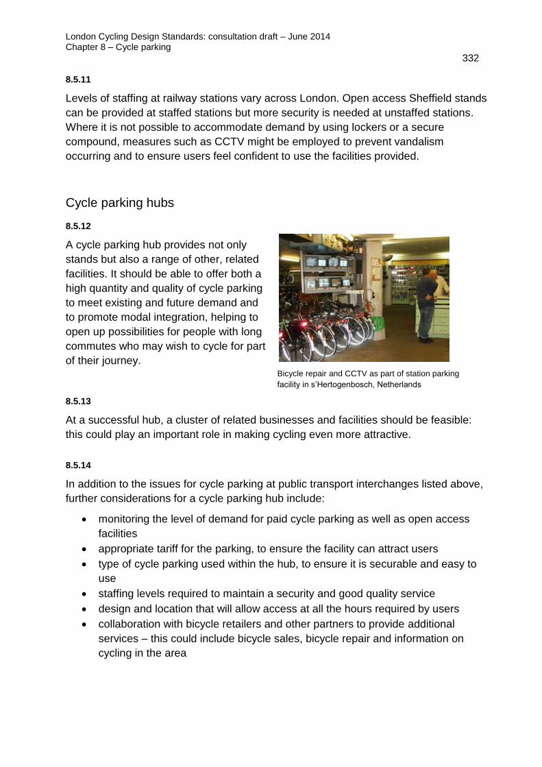
London Cycling Design Standards: consultation draft – June 2014 Chapter 8 – Cycle parking
332 8.5.11
Levels of staffing at railway stations vary across London. Open access Sheffield stands
can be provided at staffed stations but more security is needed at unstaffed stations.
Where it is not possible to accommodate demand by using lockers or a secure
compound, measures such as CCTV might be employed to prevent vandalism
occurring and to ensure users feel confident to use the facilities provided.
Cycle parking hubs
8.5.12
A cycle parking hub provides not only
stands but also a range of other, related
facilities. It should be able to offer both a
high quantity and quality of cycle parking
to meet existing and future demand and
to promote modal integration, helping to
open up possibilities for people with long
commutes who may wish to cycle for part
of their journey.
Bicycle repair and CCTV as part of station parking
facility in s’Hertogenbosch, Netherlands
8.5.13
At a successful hub, a cluster of related businesses and facilities should be feasible:
this could play an important role in making cycling even more attractive.
8.5.14
In addition to the issues for cycle parking at public transport interchanges listed above,
further considerations for a cycle parking hub include:
monitoring the level of demand for paid cycle parking as well as open access
facilities
appropriate tariff for the parking, to ensure the facility can attract users
type of cycle parking used within the hub, to ensure it is securable and easy to
use
staffing levels required to maintain a security and good quality service
design and location that will allow access at all the hours required by users
collaboration with bicycle retailers and other partners to provide additional
services – this could include bicycle sales, bicycle repair and information on
cycling in the area

London Cycling Design Standards: consultation draft – June 2014 Chapter 8 – Cycle parking
333
Housing
8.5.15
New residential developments should take every opportunity to overcome barriers to
cycling for their prospective residents and for visitors. Good quality cycle parking is a
selling-point. As a bare minimum, London Plan requirements must be met – preferably
a level of cycle parking should be provided that meets projected future demand, plus
20 per cent. Planning obligations should be used not only to require enough cycle
parking, but also to ensure that it is of high quality: well located, secure, visible, well
overlooked and fit for purpose. Developers have much to gain from making cycling an
integral part of their transport strategy should be encouraged to approach the issue
positively.
8.5.16
Additional guidance on providing cycle storage in new residential development is given
in the London Housing Supplementary Planning Guidance, adopted in November 2012.
This states that:
‘Individual or communal cycle storage outside the home should be secure, sheltered
and adequately lit, with convenient access to the street. Where cycle storage is
provided within the home, it should be in addition to the minimum GIA [gross internal
floor area] and minimum storage and circulation space requirements. Cycle storage
identified in habitable rooms or on balconies will not be considered acceptable.’
8.5.17
Residents' parking in new developments should be designed to be:
secure, with access for residents only, and with stands/racks allowing both the
frame and at least one wheel to be secured
well located: close to the entrance of the property and avoiding obstacles such
as stairs, multiple doors, narrow doorways and tight corners
covered
managed, in order for access to be administered and to provide ongoing
maintenance
Where cycle parking is provided within buildings, guidance in section 8.2 above should
be followed. This includes providing level access, avoiding multiple and narrow
doorways.
8.5.18
Options for long-stay, secure facilities for residents may include cycle compounds,
shared garages or other indoor facilities and cycle lockers. Requirements for visitors'
parking are different, but it also needs to be convenient and secure. Visitor cycle

London Cycling Design Standards: consultation draft – June 2014 Chapter 8 – Cycle parking
334
parking is usually provided in the public realm, and must be convenient and visible,
overlooked and close to the building entrance. It must be sufficient to meet visitor
demand and stands/racks must allow for the frame and both wheels to be secured.
Sheffield stands are usually fit for purpose for this use.
8.5.19
Retrofitting cycle parking into existing housing areas is more challenging than
negotiating cycle parking in new developments. A lack of cycle parking in residential
areas was identified by the London Assembly in its report Stand and deliver: cycle
parking in London (2009) as a significant factor discouraging people from taking up
cycling as a mode of transport.
8.5.20
Constraints on space and the security often lead to cycle parking being neglected.
Residents have to resort to ‘fly parking’ bicycles or storing them within their homes,
which can create security and safety hazards such as blocking sharing hallways and
staircases.
8.5.21
Much depends on housing type and tenure. Space for cycle parking for privately owned
housing usually needs to be found by individual owners within their properties, although
possibilities exist for groups of neighbours or formal residents' groups to negotiate
collective solutions. Careful management of access to facilities such as these is
needed, as well as a means for all those involved to contribute financially, as required.
8.5.22
The use of bike hangars on-street is a good example of how this can work in practice,
and local authorities should endeavour to give support and advice to ideas such as
these whenever possible, include help with TRO procedures as necessary.
8.5.23
One issue may be determining which households should be prioritised for access to
secure bicycle storage, and it may take local authority leadership to determine this
even if residents intend to manage the facility themselves. Criteria could include
whether residents could use private outdoor or indoor space, whether they would have
to negotiate stairs, how frequently they cycle and the number of cyclists in the
household.

London Cycling Design Standards: consultation draft – June 2014 Chapter 8 – Cycle parking
335 8.5.24
Housing estates may offer more opportunities for developing good quality, secure and
well-used communal cycle parking. Under-used internal spaces, such as garages, bin
stores and pram sheds, can make good cycle parking facilities with relatively simple
adjustments. In other instances, lockers and cages may be more suitable. In these
instances, cyclists typically prefer using facilities that provide access to a small number
of users.
Cycle lockers in Hackney
Cycle parking at Old Gascoyne Estate, Hackney
8.5.25
When promoting the retrofitting of cycle parking into estates, local authorities should
also engage with other key stakeholders who may provide support or need
‘convincing’. This includes:
registered social landlords / housing associations
health and well-being boards, who may support cycle parking as a contribution
to improving public health
police, who have a duty to provide crime prevention advice to residents and
boroughs
local neighbourhood teams, responsible for management of streets, who role is
also likely to include maintaining cycle parking facilities on estates
residents' associations, who may be able to apply for funding and gain local
support for new facilities
local cycling organisations
8.5.26
TfL is preparing Residential Cycle Parking Guidance, which focuses on retrofitting
cycle parking in areas of existing housing.

London Cycling Design Standards: consultation draft – June 2014 Chapter 8 – Cycle parking
336
Shops and places of work
8.5.27
Businesses operating from central London offices often struggle to provide enough
secure cycle parking for staff and visitors. If more people are encouraged to cycle
through investment provided by the Mayor's Vision for Cycling programme, then this
will place further pressure on employers to find ways of meeting demand. Commuters
often need to use on-street facilities that were designed for short-stay parking. Not only
is this less secure than formal workplace cycle parking, but it removes capacity for
short-term parking to support other uses in the area.
8.5.28
Similar issues apply to retailers. Staff should be offered good quality, long-stay cycle
parking without having to use short-stay parking on-street.
8.5.29
According to TfL's Travel in London survey 3 (2010), which included survey information
from new users of Barclays Cycle Superhighways 3 and 7, a significant number of
people who began cycling to work on the Superhighways cited improved cycle parking
facilities at work as a contributory factor – 18 per cent for users of CS3.
8.5.30
Cycle parking at workplaces is often an outcome of development control obligations or
Workplace Travel Plans that help promote sustainable transport for staff. Investment in
workplace cycle parking helps promote a mode of transport that has health and
productivity benefits as well as reducing the strain on the local transport infrastructure.
TfL's Workplace Cycle Parking Guide (2006) provides more information on initiatives
such as these.
8.5.31
In order for secure cycle parking facilities to be well used, employers will need to
engage with employees to identify the level of demand for cycle parking as well as
employee’s needs and expectations.
8.5.32
Consideration should be given to storage within buildings, cycle compounds, storage in
areas with controlled access and cycle lockers, in order to help serve the need for long-
term cycle parking from staff. There may be opportunities within many buildings to
convert part of under-used areas, such as basements and car parks, into cycle parking.
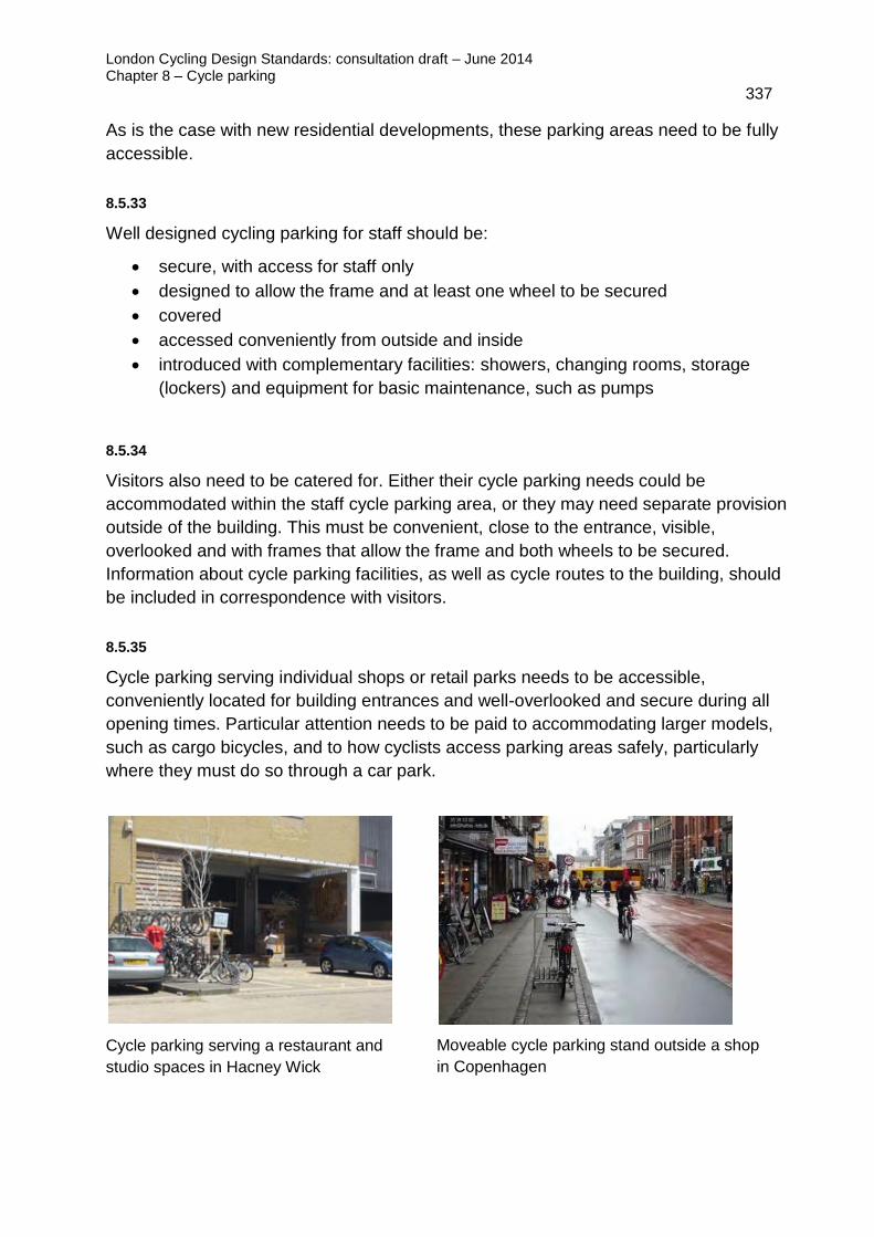
London Cycling Design Standards: consultation draft – June 2014 Chapter 8 – Cycle parking
337
As is the case with new residential developments, these parking areas need to be fully
accessible.
8.5.33
Well designed cycling parking for staff should be:
secure, with access for staff only
designed to allow the frame and at least one wheel to be secured
covered
accessed conveniently from outside and inside
introduced with complementary facilities: showers, changing rooms, storage
(lockers) and equipment for basic maintenance, such as pumps
8.5.34
Visitors also need to be catered for. Either their cycle parking needs could be
accommodated within the staff cycle parking area, or they may need separate provision
outside of the building. This must be convenient, close to the entrance, visible,
overlooked and with frames that allow the frame and both wheels to be secured.
Information about cycle parking facilities, as well as cycle routes to the building, should
be included in correspondence with visitors.
8.5.35
Cycle parking serving individual shops or retail parks needs to be accessible,
conveniently located for building entrances and well-overlooked and secure during all
opening times. Particular attention needs to be paid to accommodating larger models,
such as cargo bicycles, and to how cyclists access parking areas safely, particularly
where they must do so through a car park.
Cycle parking serving a restaurant and
studio spaces in Hacney Wick
Moveable cycle parking stand outside a shop
in Copenhagen

London Cycling Design Standards: consultation draft – June 2014 Chapter 8 – Cycle parking
338 8.5.36
In many cities with high levels of cycling, retailers often provide their own temporary
cycle parking for customers during opening hours, moving the stands back inside
overnight. This is based on understanding that convenient cycle parking is vital for their
businesses.
Cycle parking at schools
8.5.37
Good quality cycle parking facilities at schools plays an important role in influencing the
travel choices of young people. The right provision will depend on the age group of the
children, and the range in sizes of bikes to be parked, as well as the cycle parking
needs of staff.
8.5.38
Good quality cycle parking at schools should be:
located within footprint of the facility
easily accessible – clustered close to entrances/exits
visible, open and overlooked – to serve staff, students and visitors
covered
8.5.39
It is important that cycle parking is not located in areas where conflict is likely with
motor vehicle access to and from car parks. Similarly, it should not be located near
drop-off points.
8.5.40
Schools are generally fenced and gated, are open only during certain hours, are staffed
and are on private land. It may therefore be that existing security in the school grounds
is adequate and that a secured compound is not required. It may be advisable,
however, to operate a system where staff lock and unlock facilities at the beginning and
end of the school day so as to protect any bicycles left overnight.

London Cycling Design Standards: consultation draft – June 2014 Chapter 8 – Cycle parking
339
Large, multi-access sites
8.5.41
Large multi access sites such as hospitals, universities and colleges tend to have
large numbers of people both working and visiting the sites. Cycle parking provision
at such land uses are likely to cater for both long stay demand for staff and or
students, but also for short to medium stays, given that they have a high daily
turnover of students, staff and visitors.
8.5.42
Such sites often have a number of entrances and exits. Cycle parking therefore needs
to be carefully planned in clusters, convenient for users, and located near to the
entrances and exits that have higher levels of natural surveillance and footfall.
8.5.43
At sites where access may be permitted for 24 hours or beyond the normal working
day, particular consideration is required of lighting and levels of surveillance after dark,
and how safe the user feels accessing the parking.

London Cycling Design Standards consultation draft – June 2014 i
Appendix – Cyclists at Roadworks Guidance
Appendix
Cyclists at roadworks
This appendix provides guidance for those planning, designing and operating
temporary traffic management associated with construction activities on the highway to
ensure that the convenience and safety of cyclists is fully considered alongside the
needs of all other road users, as well as those undertaking the works.
It is important for temporary traffic management designers to examine and assess
each and every site individually and not just apply standard layouts. Each option
should be carefully considered and risk assessed to ensure that the most appropriate
option is taken forward.
It is essential that temporary works are observed, maintained and monitored, with any
risks and issues continuously addressed.
The guidance was developed jointly by a group of contributing organisations: AECOM,
Amey, EnterpriseMouchel, Ringway Jacobs and Transport for London. It was written
primarily for works undertaken on the Transport for London Road Network but it can
also be applied to similar urban roads.
Background
Documents such as chapter 8 of the Traffic Signs Manual and Safety at Street Works &
Road Works, a Code of Practice (the ‘Red Book’, 2013) refer to the need to consider
cyclists when designing temporary traffic management. This appendix provides further
detail on those considerations and takes forward ideas outlined in the Traffic Advisory
Leaflet TAL 15/99 Cyclists at Roadworks (1999).
The Mayor’s Vision sets out a pro-active approach to improving provision for cyclists
through temporary layouts, stating that: ‘We will monitor roadworks and building
schemes to avoid unnecessary disruption to cycle routes. Following the standard set
by Crossrail works at Farringdon, we will try to ensure that even when a road is closed
to motor traffic, passage is still provided for bikes.’
Traffic lane widths in the range of 3.2 to 3.9m where there is no dedicated cycle lane.
These provide pinch points and a level of uncertainty about whether safe overtaking is
possible between cyclists and drivers. (Note that TAL15/99 suggests that lane widths
of 3.25m and above are adequate for cars to overtake cyclists, but goes on to
demonstrate that around 4m is needed for larger vehicles to overtake safely.)

London Cycling Design Standards consultation draft – June 2014 ii
Appendix – Cyclists at Roadworks Guidance
Issues for consideration
There are a number of potential hazards or impacts that must be considered when
designing ‘cycle friendly’ temporary traffic management. These include:
pinch points that ‘squeeze’ cyclists
removal or obstruction of existing cycle lanes or tracks
unacceptably long diversion routes
inappropriate use of temporary ‘cyclists dismount’ signs: where a clear route has
been maintained, cyclists should still be able to use the carriageway
poor temporary road surfaces, including raised ironworks
raised cable protectors, hoses or road plates
road closures (without cyclist exemption)
one-way working (without cyclist exemption)
cyclists entering the work site
measures to avoid conflicts between cyclists and other vulnerable road users
Consideration of these issues should be made from the outset of every project,
whether it is a major scheme or minor maintenance.
The issues that should be considered when developing the detailed temporary
management proposals are as follows.
Temporary speed limits
Where road widths are limited but sufficient volumes
of cycle traffic exists, consideration should be given to
lowering the speed limit or a temporary maximum
speed recommendation to encourage motorised
vehicles to either safely overtake or follow cyclists.
This will require a Traffic Order.
A temporary speed limit may also be required or
desirable for other reasons such as to reduce risk to
site operatives. Changes to speed limits could be
either mandatory or advisory, depending on the
duration of the works.
Temporary speed limit sign

London Cycling Design Standards consultation draft – June 2014 iii
Appendix – Cyclists at Roadworks Guidance
Lane widths
Temporary lane widths through road works should be designed for cyclists comfort as
well as safety. The key initial considerations are whether cyclists are predominantly on
or off the carriageway and, if on carriageway, what the volume, speed and composition
of motor traffic is. Transitions to and from areas with traffic management layouts are
also important and consideration needs to be given to ways of preventing cyclists being
‘squeezed’ by manoeuvring vehicles at the lead-in taper.
Where cyclists are on-carriageway and the speed limit is 30mph or 20mph, it is usually
desirable to keep them on carriageway through the roadworks. In this case, a wide
lane (minimum width of 4m) enables drivers of all motor vehicles to overtake cyclists
with an acceptable clearance.
If a 4m lane width cannot be achieved then, according to advice given in TAL 15/99
Cyclists at Roadworks (1999), a ‘narrow’ lane width of up to 3.25m to 3.50m will enable
car drivers to overtake comfortably and will generally deter drivers of larger vehicles
from trying to pass at all. If even 3.25m cannot be provided, then a ‘narrow’ lane width
of up to 3.25m and a speed limit of 20mph should be considered with signs stating
‘narrow lane(s): do not overtake cyclists’.
Lane widths between 3.50m and 4m should normally be avoided as drivers of large
vehicles may attempt to overtake cyclists without adequate clearance.
On higher speed roads (40mph), there will often be off-carriageway provision for
cyclists which they should be encouraged to use through signing, though cyclists will
usually also be permitted to use the carriageway. In these cases, a minimum lane
width of 4.25m should be used through the roadworks to enable comfortable overtaking
of cyclists. Where this cannot be achieved, a speed limit of 30mph should be
considered in conjunction with a 3.25m to 3.50m or 4m lane width, or a 20mph speed
limit and ‘narrow’ lane as described above. Consideration should be given to the need
for extra width at bends and turns in traffic management layouts.
On roads with speed limits of 50mph or more, scheme specific measures appropriate
to the existing provision and use by cyclists should be provided.
On prestige cycle routes, including Cycle Superhighways, or routes with high peak time
cycle flows (> 10 per cent of vehicles), consideration should be given to arranging the
works layout such that temporary cycle lanes can be provided. Where it is not feasible
to maintain two-way traffic and where there are significant cycle flows, consideration
should be given to providing a cycle contra-flow facility. This will be particularly
beneficial where a diversionary route would satisfy one or more of these conditions:
be in place for a long period
involve significantly greater effort owing to distance and gradients
put cyclists at greater risk due to the road layout and traffic conditions

London Cycling Design Standards consultation draft – June 2014 iv
Appendix – Cyclists at Roadworks Guidance
Contraflow cycle facilities should be a minimum of 1.2m wide (recommended 1.5m)
and may require some physical segregation from opposing traffic, based on site-
specific risk assessment.
It should be noted the minimum lane width recommended in the DfT code of practice,
Safety at Street Works and Road Works (2013), to enable the passage of buses and
HGVs is 3m.
Summary of recommended lane widths at roadworks
<3.25m Consider 20mph speed limit and ‘Narrow lane: do not overtake
cyclists’ sign
3.25 to 3.5m Too narrow for drivers of large vehicles to overtake but cars
can pass cyclists
3.5 to 4.0m To be avoided
4.0m+ Wide enough for all vehicles to overtake on lower speed roads
(20mph)
4.25m+ Wide enough for all vehicles to overtake on higher speed roads
Note that these are different from the recommended widths in LCDS section 4.4,
because they take into account effective width for cyclists in scenarios where there is a
physical barrier on both sides of the lane.
Traffic signal timings
Temporary traffic signals should give cyclists sufficient opportunity to pass safely
through road works (appropriate intergreen times should be used, see also ‘Lengths of
road works’ below), particularly where oncoming motor vehicles cannot pass without
conflict. When specifying the most appropriate arrangements, consideration should be
given to clearance times for cyclists, particularly on steep hills.
Length of road works
Cyclists are generally more at risk through road works, so limiting the length of the site
should be considered. For example, if a scheme is to be constructed over 100m and a
cycle facility or wide traffic lanes (4m+) cannot be provided, then it should, where
possible, be completed in shorter sections to reduce the exposure of cyclists travelling
through pinch points. If the length of the work site cannot be adapted, and there is
significant cycle demand, then an alternative off road cycling facility or other measures
such as a general traffic diversion should be considered.

London Cycling Design Standards consultation draft – June 2014 v
Appendix – Cyclists at Roadworks Guidance
Maintaining access
Wherever possible, access should be maintained for cyclists in both directions
throughout the period of road works, avoiding more hazardous diversions. Cyclists are
unlikely to accept lengthy detours or long delays. In such conditions some cyclists will
be tempted to ride contra-flow or use footways. This can be avoided by, for instance,
providing a temporary segregated cycle lane, shared path or route away from the
carriageway. This kind of provision will be most desirable on dual carriageways.
Temporary route signing
Temporary routes and other facilities for the exclusive use of cyclists (and pedestrians)
should be clearly signed well in advance of the road works. The examples shown
below are sign face template examples. Other temporary signs such as ‘Cyclists use
ramp onto footway’ may also be useful.
It should be noted that signs marked ** below do not have specific Department for
Transport approval. However Regulation 53.(1).(e).(i) of TSRGD (2002) states ‘in this
regulation ‘temporary sign’ means a sign placed on or near a road for the purpose of
conveying to traffic warnings about, or information on how to avoid, any temporary
hazards caused by works being executed on or near a road’. It is for highway
authorities to define what constitutes a specific ‘hazard’ in any given location, but there
is a strong case for regarding narrow lanes as such a hazard for cyclists.

London Cycling Design Standards consultation draft – June 2014 vi
Appendix – Cyclists at Roadworks Guidance
Note that narrow lanes may not be the only reason why there may be a design to
instruct drivers not to overtake cyclists. Greater risk at bends and corners may also
justify a ‘do not overtake’ sign.
Road surface
It should be borne in mind that cyclists are particularly vulnerable to uneven, slippery or
excessively rough surfaces. Therefore, consideration should be given to phasing of
works to avoid temporary surfaces or raised ironwork.
If cyclists are to be signed via a diversion route, then the surfacing on this alternative
alignment should be checked and corrected if necessary before the diversion is
introduced. Where raised iron work is unavoidable, in addition to warning signs,
consideration should be given to marking it in a contrasting colour to improve visibility,
in addition to warning signs.
Barriers
It has been identified that cyclists will often pass through a line of cones and enter the
works safety zone, and even the works area on occasion. This could be minimised by
the use of a solid barrier and closely spaced cones in the taper and the first metre, then
normal cone spacing along the remaining length, whilst also providing barriers
alongside the linear safety zone. This would provide a clearer obstruction to cyclists, to
discourage encroachment into the working and safety zones.
Road Safety Audit
A Road Safety Audit may be required for temporary traffic management schemes. TfL
policy is that such schemes will not generally require auditing unless they remain in
operation for a period of six months or more. Consideration should be given to auditing
temporary traffic management schemes that are to remain in operation for a period of
less than six months if a significant impact on the highway network is anticipated.
Temporary traffic management layouts
Some schematic drawings adopting the general principles detailed in section 3 have
been developed in order to assist with the design of temporary traffic management to
cater for cyclists more adequately.
In developing the most appropriate solution, reference should also be made to the
‘Cyclists and temporary traffic management design checklist’ below.

London Cycling Design Standards consultation draft – June 2014 vii
Appendix – Cyclists at Roadworks Guidance
The overall risk to cyclists should be considered on a case-by-case basis, taking into
account, firstly, the number of cyclists and the effect that the proposed works and
resultant temporary traffic management will have on their journey. The assessment
should include an estimation of the relative cycle and non-cycle flows. If a significant
number of cyclists will be affected by road works, then they should be provided for
specifically in the design of temporary traffic management. If an existing facility exists,
every effort should be made to maintain it.
There are a number of actual and hypothetical scenarios in the ‘worked examples’
section below, providing further commentary and drawings relating to measures for
cyclists at road works.
‘Cyclists dismount’ signs
Simply placing a ‘cyclists dismount’ sign at each of the works is not acceptable and is
only to be used where there is no vehicular access of any kind through the works. It
should be noted that in cases such as option 2 below, the presence of a
shared/segregated footway avoids the need for ‘cyclists dismount’ signs. The use of
this sign has not been covered in this guidance because there is invariably a more
suitable solution.

London Cycling Design Standards consultation draft – June 2014 viii
Appendix – Cyclists at Roadworks Guidance
Cyclists and temporary traffic management design checklist
Project name:
Location:
Road number: TLRN / SRN / borough?
AADT (two-way):
Peak hour cycle flow (two-
way):
Per cent of commercial
vehicles
Existing cycle facilities Proposed temporary cycle facilities
Direction 1: Direction 1:
Direction 2: Direction 2:
Junction 1: Junction 1:
Junction 2: Junction 2:
Existing speed limit (mph): Proposed speed limit
(mph):
Existing no. of lanes: Proposed no. of lanes:
Existing nearside lane
width (m) if no cycle lane:
Proposed nearside lane
width (m) if no cycle lane:
Y, N or n/a
Existing cycle facilities maintained? If not, see below.
Lane widths appropriate for cyclists?
Alternative off-carriageway cycle facility necessary?
Temporary off carriageway cycle facility signed and TTRO?
Intergreen timings at temporary signals suitable for cyclists?

London Cycling Design Standards consultation draft – June 2014 ix
Appendix – Cyclists at Roadworks Guidance
Intergreen timings suitable for cyclists on steep gradients?
Temporary signal cables in existing ducts or use wireless
portable traffic signals?
Temporary ASL provided if temp signals layout over 30 days?
Barriers / closely spaced cones to deter cycle encroachment?
Cycle ‘escape areas’ provided, where continuous barriers?
Length and number of pinch points minimised?
All access maintained for cyclists?
Off line cycle diversion required?
Cycle safety, and surface checked on diversion?
Cyclists at Road Works – Guidance Document 15
Cyclists dismount signs provided? Only if all alternatives have been
rejected?
Cycling prohibited signs provided, if no suitable alternative?
If narrow lanes, ‘do not overtake cyclists’ signs specified?
Offside merge provided on two lane carriageways?
Bus stops suspended in works area?
Is a Road Safety Audit required as per TfL SQA0170?

London Cycling Design Standards consultation draft – June 2014 x
Appendix – Cyclists at Roadworks Guidance
Traffic management option 1 – Temporary cycle lane on carriageway
If an existing cycle facility exists either on a wide single lane carriageway or on a dual
carriageway, the priority should be to maintain the facility ‘on-line’ using temporary
signs, cones / barriers and road markings as required. The costs and disruption
associated with the application (and subsequent removal) of new line markings should
be balanced against a temporary facility provided by a line of cones. As such, line
marking a temporary cycle facility is unlikely to be practical for layouts in place for less
than 30 days. (See Traffic Management Layouts A, B and C)
Traffic management option 2 – Temporary shared path on footway
Should it not be practicable to maintain an ‘on-carriageway’ facility and where an
adjacent footway of at least 3m is available, consideration could be given to temporarily
diverting the cyclists on to the footway. There may be some locations where a slightly
narrower footway could be considered (2m absolute minimum) if there is no street
furniture obstructing the footway and the timing of the works is such that pedestrian
and cycle flows are low. The most convenient diversion requiring the least movement
away from the cyclists’ desire line should be used.
Should the footway be wide enough and have no trips or hazards a temporary
dedicated cycle track could be considered, though shared use would be simpler and
easier to implement, depending on the site specific details, the pedestrian and cycle
flows and whether it is 1 or 2-way. Dropped kerbs for access to and egress from the
footway will be necessary or a secure temporary ramp could be provided.
The need for a buffer/safety zone for cyclists on the footway from any adjacent traffic
should also be considered for safety reasons. The use of this option will require a
Temporary Traffic Management Order or Notice of the temporary cycle facility,
appropriate signing and involve consultation / advertising periods (of up to 6 weeks).
(See Traffic Management Layout D)
Traffic management option 3 – Temporary speed limit on carriageway
A temporary reduced speed limit is an option if a high volume of cycle traffic exists and
if it is desirable to keep cyclists on the carriageway. A lower speed limit allows cyclists
to be followed or overtaken by cars at reduced clearances, useful in situations where
lane widths are limited. The temporary speed limit could be either advisory or
mandatory.
Where works are due to be completed within 60 days it is suggested that an advisory
lower speed limit is signed (see sign face template examples above). Where works are
due to last longer than 60 days, a mandatory lower speed limit should be considered.

London Cycling Design Standards consultation draft – June 2014 xi
Appendix – Cyclists at Roadworks Guidance
Where narrow lanes are provided, such that it is not wide enough for motor vehicles to
safely overtake cyclists, an advisory speed limit of 20mph should be considered
through the road works. (See Traffic Management Layouts E and F)
Traffic management option 4 – Reduced available lane widths
Where no on-line or reasonable off-line facility can be provided, reducing the available
lane widths to discourage overtaking movements should be considered. (See Traffic
Management layouts G and H) This would also have an effect of reducing vehicle
speeds. Practically, a restriction of this nature would not be enforceable but can be
signed using a temporary sign warning of the hazard caused by works being carried
out on or near the road.
Recent observations of a temporary one way traffic management layout suggest that
the reduction of a lane to 3.0m will strongly deter large vehicles from attempting to
overtake cyclists. Alternatively consider making the works and working area narrower
to enable provision of a cycle lane within the remaining carriageway width.
Traffic Management Layout 5 – Motorist diversion
Practitioners should be aware that cyclists should not be unreasonably disadvantaged
compared to motor traffic and may not use a long or poor quality diversion. A risk
assessment should be undertaken to establish whether motorised traffic should be
diverted whilst allowing cycle traffic to continue adjacent to the works area. (See Traffic
Management layout I)
Depending on the length of the closure you may need to consider a no through road
option for service vehicles with a gateway / point closure beyond which only cycles
may pass in accordance with ‘no entry except cycles’ signage (authorised by DfT in
November 2011). Note the use of ‘road ahead closed except cycles’ signage is
currently being discussed with DfT in terms of authorisation.
Traffic management option 6 – Off-line cyclist diversion
Should it not be practicable to maintain acceptable provision for cycling through the
road works, the most convenient off-line diversion should be sought. This option could
be appropriate where a full road closure is intended and a shorter/alternative diversion
for cyclists than for motorists is possible (see Worked Example 2).
This option may also be useful where the road works are closing an off carriageway
cycle facility and it is not appropriate to simply direct cyclists adjacent to the works via
the carriageway.

London Cycling Design Standards consultation draft – June 2014 xii
Appendix – Cyclists at Roadworks Guidance
Where a diversion is proposed, provision and maintenance of appropriate signing is
vital (see example signs above). Assessment should be undertaken of the diversion
route to ensure that it is suitable for cyclists, including: surface condition, suspension of
prohibitions, right turn movements designed out / or cyclists routed via signals so right
turn movements can take place under signal control. (See Traffic Management Layout
J)
When designing the cycle diversion care should be taken to avoid the potential issue of
motorists following the cycle diversion signs. This can sometimes be the case with
black on yellow signage, therefore the need to make the cycle route as clear as
possible to both general traffic and cyclists is paramount. This could be achieved by
using versions of the signs with special symbols ie. black on yellow with text such as
‘Cyclists follow [diamond symbol]’ or similar.