
Manual Revision: 12/19/2013
For the most up-to-date information, please visit: www.startech.com
DE: Bedienungsanleitung - de.startech.comFR: Guide de l'utilisateur - fr.startech.comES: Guía del usuario - es.startech.comIT: Guida per l'uso - it.startech.comNL: Gebruiksaanwijzing - nl.startech.comPT: Guia do usuário - pt.startech.com
25SAT22MSAT
Dual mSATA SSD to 2.5in SATA SSD Converter w/ RAID
*actual product may vary from photos
Instruction Manual
FCC Compliance StatementThis equipment has been tested and found to comply with the limits for a Class B digital device, pursuant to part 15 of the FCC Rules. These limits are designed to provide reasonable protection against harmful interference in a residential installation. This equipment generates, uses and can radiate radio frequency energy and, if not installed and used in accordance with the instructions, may cause harmful interference to radio communications. However, there is no guarantee that interference will not occur in a particular installation. If this equipment does cause harmful interference to radio or television reception, which can be determined by turning the equipment off and on, the user is encouraged to try to correct the interference by one or more of the following measures:
• Reorient or relocate the receiving antenna.
• Increase the separation between the equipment and receiver.
• Connect the equipment into an outlet on a circuit different from that to which the receiver is connected.
• Consult the dealer or an experienced radio/TV technician for help.
Use of Trademarks, Registered Trademarks, and other Protected Names and SymbolsThis manual may make reference to trademarks, registered trademarks, and other protected names and/or symbols of third-party companies not related in any way to StarTech.com. Where they occur these references are for illustrative purposes only and do not represent an endorsement of a product or service by StarTech.com, or an endorsement of the product(s) to which this manual applies by the third-party company in question. Regardless of any direct acknowledgement elsewhere in the body of this document, StarTech.com hereby acknowledges that all trademarks, registered trademarks, service marks, and other protected names and/or symbols contained in this manual and related documents are the property of their respective holders.
Instruction Manuali
Table of ContentsProduct Diagram ....................................................................................1
Front View .................................................................................................................................................... 1
Back View ..................................................................................................................................................... 2
Introduction ............................................................................................2Packaging Contents ................................................................................................................................. 2
System Requirements .............................................................................................................................. 2
mSATA SSD Installation .........................................................................3
Configure RAID .......................................................................................5RAID Lock/Unlock Jumper Pins ............................................................................................................ 5
RAID Mode Setting Jumper Pins .......................................................................................................... 5
Set RAID Configuration ........................................................................................................................... 6
Hard Drive Initialization ........................................................................6
LED Activity and Drive Failure Indicators ...........................................8
Technical Support ..................................................................................9
Warranty Information ............................................................................9
Instruction Manual1
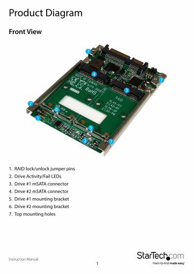
Product Diagram
Front View
1. RAID lock/unlock jumper pins
2. Drive Activity/Fail LEDs
3. Drive #1 mSATA connector
4. Drive #2 mSATA connector
5. Drive #1 mounting bracket
6. Drive #2 mounting bracket
7. Top mounting holes
Instruction Manual2
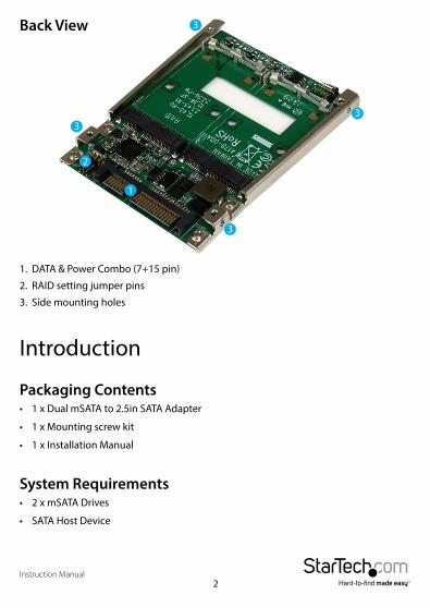
Back View
Introduction
Packaging Contents• 1 x Dual mSATA to 2.5in SATA Adapter
• 1 x Mounting screw kit
• 1 x Installation Manual
System Requirements• 2 x mSATA Drives
• SATA Host Device
1. DATA & Power Combo (7+15 pin)
2. RAID setting jumper pins
3. Side mounting holes
Instruction Manual3
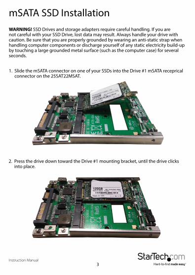
mSATA SSD InstallationWARNING! SSD Drives and storage adapters require careful handling. If you are not careful with your SSD Drive, lost data may result. Always handle your drive with caution. Be sure that you are properly grounded by wearing an anti-static strap when handling computer components or discharge yourself of any static electricity build-up by touching a large grounded metal surface (such as the computer case) for several seconds.
1. Slide the mSATA connector on one of your SSDs into the Drive #1 mSATA receprical connector on the 25SAT22MSAT.
2. Press the drive down toward the Drive #1 mounting bracket, until the drive clicks into place.
Instruction Manual4
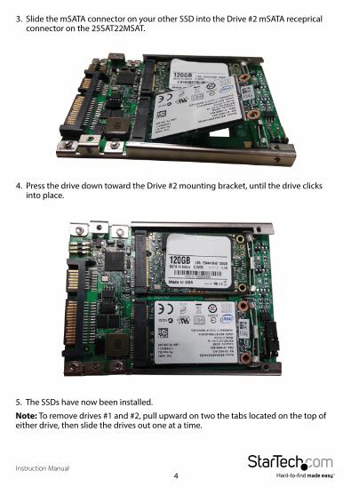
3. Slide the mSATA connector on your other SSD into the Drive #2 mSATA receprical connector on the 25SAT22MSAT.
4. Press the drive down toward the Drive #2 mounting bracket, until the drive clicks into place.
5. The SSDs have now been installed.
Note: To remove drives #1 and #2, pull upward on two the tabs located on the top of either drive, then slide the drives out one at a time.
Instruction Manual5
Configure RAIDWARNING! Setting or changing your RAID modes will erase the data or metadata on your existing SSD drives.
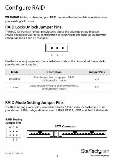
RAID Lock/Unlock Jumper PinsThe RAID lock/unlock jumper pins, located above the drive mounting brackets enable you to lock your RAID configuration so it cannot be changed. Or unlock your configuration so it can be changed.
Use the included jumper and the table below, to short the pins and set the mode for your desired configuration.
Mode Description Jumper Pins
Unlocked Enables you to change your RAID configuration mode. 2-3
Locked Does not allow you to change your RAID configuration mode. 1-2
123
RAID Mode Setting Jumper PinsThe RAID setting jumper pins, located next to the SATA connector enable you to set your desired RAID configuration between RAID 0, RAID 1, JBOD, and RAID initial Mode.
4 5 6
1 2 3
RAID Setting Jumper Pins
SATA Connector
Instruction Manual6
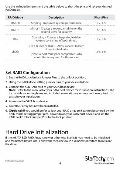
Use the included jumpers and the table below, to short the pins and set your desired RAID mode.
RAID Mode Description Short Pins
RAID 0 Striping - Improves system performance 1-2, 4-5
RAID 1 Mirror – Creates a redundant drive on the second drive for security 2-3, 4-5
BIG Spanning – Creates a large single drive volume consisting of both drives. 1-2, 5-6
JBOD
Just a Bunch of Disks – Allows access to both drives individually
(Note: A port multiplier compatible SATA controller is required for this mode)
2-3, 5-6
Set RAID Configuration1. Set the RAID Lock/Unlock Jumper Pins to the unlock position.
2. Using the RAID Mode setting jumper pins to your desired Mode.
3. Connect the SSD RAID card to your SATA host device. Note: Refer to the manual for your SATA host device for installation instructions. The top or side mounting holes and included screw kit may, or may not be required to assist in your installation.
4. Power on the SATA host device.
5. Your RAID array has now been installed.
6. (Optional) If you would prefer to lock your RAID array so it cannot be altered by the RAID mode setting jumper pins, power down your SATA host device, and set the RAID Lock/Unlock Jumper Pins to the lock position.
Hard Drive InitializationIf the mSATA SSD RAID Array is new or otherwise blank, it may need to be initialized and formatted before use. Follow the steps below in a Windows interface to initialize the drive.
Instruction Manual7
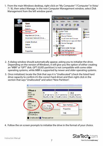
1. From the main Windows desktop, right-click on “My Computer” (“Computer” in Vista/ 7 / 8), then select Manage. In the new Computer Management window, select Disk Management from the left window panel.
2. A dialog window should automatically appear, asking you to initialize the drive.Depending on the version of Windows, it will give you the option of either creating an “MBR” or “GPT” disk. GPT (GUID partition) is not compatible with some older operating systems, while MBR is supported by newer and older operating systems.
3. Once initialized, locate the Disk that says it is “Unallocated” (check the listed hard drive capacity to confirm it’s the correct hard drive) and then right-click in the section that says “Unallocated” and select “New Partition”.
4. Follow the on screen prompts to initialize the drive in the format of your choice.
Instruction Manual8
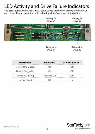
LED Activity and Drive Failure IndicatorsThe 25SAT225MSAT includes an LED panel to visually monitor activity and failure of each drive. Please review the table below for a list of each specific indication.
Activity for Drive #1
Activity for Drive #2
Failure for Drive #1
Failure for Drive #2
Description Activity LED Drive Failure LED
Device Unplugged Off Off
Device Plugged in On Off
Device Accessing Flashing On Off
Device Failed Off On
Instruction Manual9
Technical SupportStarTech.com’s lifetime technical support is an integral part of our commitment to provide industry-leading solutions. If you ever need help with your product, visit www.startech.com/support and access our comprehensive selection of online tools, documentation, and downloads.For the latest drivers/software, please visit www.startech.com/downloads
Warranty InformationThis product is backed by a two year warranty. In addition, StarTech.com warrants its products against defects in materials and workmanship for the periods noted, following the initial date of purchase. During this period, the products may be returned for repair, or replacement with equivalent products at our discretion. The warranty covers parts and labor costs only. StarTech.com does not warrant its products from defects or damages arising from misuse, abuse, alteration, or normal wear and tear.
Limitation of LiabilityIn no event shall the liability of StarTech.com Ltd. and StarTech.com USA LLP (or their officers, directors, employees or agents) for any damages (whether direct or indirect, special, punitive, incidental, consequential, or otherwise), loss of profits, loss of business, or any pecuniary loss, arising out of or related to the use of the product exceed the actual price paid for the product. Some states do not allow the exclusion or limitation of incidental or consequential damages. If such laws apply, the limitations or exclusions contained in this statement may not apply to you.

Hard-to-find made easy. At StarTech.com, that isn’t a slogan. It’s a promise.
StarTech.com is your one-stop source for every connectivity part you need. From the latest technology to legacy products — and all the parts that bridge the old and new — we can help you find the parts that connect your solutions.
We make it easy to locate the parts, and we quickly deliver them wherever they need to go. Just talk to one of our tech advisors or visit our website. You’ll be connected to the products you need in no time.
Visit www.startech.com for complete information on all StarTech.com products and to access exclusive resources and time-saving tools.
StarTech.com is an ISO 9001 Registered manufacturer of connectivity and technology parts. StarTech.com was founded in 1985 and has operations in the United States, Canada, the United Kingdom and Taiwan servicing a worldwide market.


