
Dually Operated Control Cupola Furnace with Maintaining Constant Air Blast for Improving Production Gain of Iron
International Journal of Mechatronics and Applied Mechanics, 2020, Issue 8, Vol. II 165
DUALLY OPERATED CONTROL CUPOLA FURNACE WITH MAINTAINING CONSTANT AIR BLAST FOR IMPROVING
PRODUCTION GAIN OF IRON
Huzifa A. Fidvi1, Dr. Akash M. Langde1
1Anjuman College of Engineering and Technology, Mangalwari Bazaar Road, Sadar, Nagpur-440001, India Email: [email protected]
Abstract - Cupola furnace is the most commonly used for the melting of ferrous metals and alloys. The key challenge in this paper is variation of air blast which lead to productivity loss and moreover affects the small scale industries. In order to overcome the above key challenge our work has proposed a Dually Operated Control Cupola Furnace which states that constant air blast can be obtained by controlling manually as well as automatic. Manual operation is obtained by maintaining constant Motor-Torque-Speed-Ratio using inverter driven blower along with space vector pulse width modulation. Automatic operation inhabits a feedback control system using nonlinear model predictive controller which is operated on control valve driven blower. Automatic operated cupola furnace obtains a prediction value for obtaining the productivity gain based on number of experimental observations and overall gives the required constant air blast by considering blast volume, blast temperature and oxygen enrichment. Thus our model enhances the system performance by achieving productivity gain in terms of melting rate and super heating temperature. Keyword: Bridge Rectifier, Inverter, Vector Space Pulse Width Modulation, Parameterized NMPC, Microcontroller, Oxygen, and Temperature Sensor, Control Valve, Pressure Gauge.
1. Introduction Cupola is a furnace that is used to melt metal scrap, cast iron scrap and cast iron alloys. It is one of the oldest methods of cast iron production and, due to its simplicity and low fuel cost, it remains the dominant method [1]. The main source of energy is coal coke. The size of cupolas ranges from 18 inches to 13 feet in diameter and can produce cast iron up to 100 tons per hour [2].
There are several unique features of the cupola furnace that are responsible for its widespread use. The cupola is one of the only melting methods in its process that is continuous [3]. High rates of melting.
The operating costs are relatively low. Facility to run. While cupola melting has a long history, because the process was poorly understood, automatic control was elusive. Most foundries rely on experienced operators ' intuition to make control decisions [4].
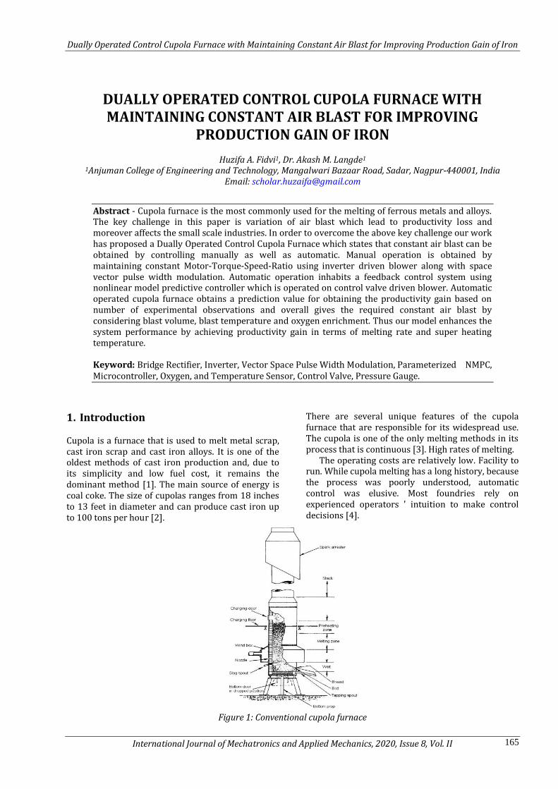
Figure 1: Conventional cupola furnace
Dually Operated Control Cupola Furnace with Maintaining Constant Air Blast for Improving Production Gain of Iron
International Journal of Mechatronics and Applied Mechanics, 2020, Issue 8, Vol. II 166
Originally, the process of the cupola furnace consists of steel, alloy materials, calcareous and coal coke for fuel and carbonization (8-16% of the metal load), which is fed in alternating layers through the cylinder opening [5]. Air enters the bottom through tuyers that extend a short distance into the cylinder's interior. The air intake also includes increased levels of oxygen [6]. Coke is drunk. Through the trigger, the hot exhaust gas increases, preheating it. This enhances the furnace's energy efficiency [7]. The load is falling and melted. Because air is fed into the furnace, it is a reduction in the atmosphere. Under reduced conditions, coke burning raises the carbon content of the metal charge to the casting specifications [8].
A thermodynamic reaction occurs in the blast air between the fuel and the oxygen during the melting process.
Combustion Zone: The coke's carbon combines with air oxygen to
form heat releasing carbon dioxide. Heat also develops as a result of silicon oxidation [9].
heatcooc 22 (1)
heatsioosi 22 (2)
heatMnooMn 22 22 (3)
Reducing Zone: The carbon dioxide continues to burn to form
low-heat carbon monoxide.
heatcocokeCco 2)(2 (4)
Some of the carbon is picked up by the dropping
droplets of molten metal, which may last a few hours, a day, weeks or even months to raise the carbon content of the iron A production run, called a' cupola project.' Molten iron additives such as ferromanganese, ferrosilicon, silicon carbide and other alloying agents are used to modify the molten iron to meet the needs of the castings at hand [10].
Melting zone: The first layer of pig iron above the first coke bed
is included. In this zone, the pig iron is melted. There is the following reaction [11].
2323 CoCFeCoFe (5)
Preheating area Contains all layers of cupola charges placed at the top of the last charge above the melting region. Charging layers are heated by the exhaust gases. The zone temperature may be as high as 1050 ° C [12].
Stack: This is the area beyond the pre-heating zone
where the warm gasses go into the atmosphere. Cupola furnace undergoes many benefits as it is
easy and economical to operate; a Cupola can
accommodate a wide range of materials without reducing the quality of melting [13]. Dirty, oily scrap and a wide range of steel and iron can be melted. [14]. This is because they extract energy directly from coke rather than electricity which needs to be produced first, the continuous rather than batch process complies with the specifications of a repetition foundry, Cupolas can be used to recycle foundry by-products and to remove other contaminants such as VOC from the core production area, high melting levels, ease of use, adequate temperature control, chemical c[15]. The formation of slag starts in the melt zone where the metal pieces begin to melt due to heat.
The naturally formed slag (without the slag-forming additives) is made up of SiO2 and Al2O3, as well as iron, manganese, magnesium, phosphorus and sulphides oxides. Spontaneously shaped slag has a high viscosity that hinders the process of melting. Slag-forming additives are applied to reduce the melting temperature of the slag in order to improve the slag properties. [16-19]
Cupola furnace used to melt pig iron or scrap metal into cast iron. Utilization of cast iron is In order to overcome all the challenges mentioned above our work has introduced a novel model, which has the capability to face the challenges Therefore the upcoming sections will give an overall clear view of the model, section 2 states with Related Works, section 3 states with our Proposed Work Methodology, and section 4 discuss with Result Analysis along with Result Comparisons, section 5 concludes with our proposed model work.
2. Literature Survey A. Jopkiewicza et al [20] shows that using the hot wind or the wind enriched with oxygen, the divided blast system, using the additional gaseous fuel or even total elimination of coke from cupolas are discussed. The cupola was described with partial gas recycling and the use of plasma burners. Opportunities to use pulsating gas flows as well as environmental concerns and concepts of dynamic regulation of cupola processes were also suggested.
Charles F. Codrington et al [21] invention relates to improvements in centrifugal blowers used for supplying the air necessary for combustion of the fuel in metal melting cupolas. It provide a control system for centrifugal blowers in which air inlet control means are controlled by air weight responsive means for controlling the weight of air discharged from the blower regardless of the discharge pressure.
Lee Robert S et al [22] invention relates to an improved tuyer having provisions for controlling the blast of air so as to increase the production and quality of the iron produced.
Another object is to provide an improved efficient and simplified control for directing air which is precise and easily operable.
Dually Operated Control Cupola Furnace with Maintaining Constant Air Blast for Improving Production Gain of Iron
International Journal of Mechatronics and Applied Mechanics, 2020, Issue 8, Vol. II 167
H. A. REECE [23] Patent aims to provide a novel construction and method of operation for a furnace of the cupola type. The attainment of uniform condition, the velocity, and volume of air which slag accumulations will form on the tuyers are very important factors. Mechanically actuated shutter means is employed for pausing the temporary` sequential interrupting or restricting the air flow to the- tuyers.
WILLIAM A; O'BRIEN [24] this invention relates to the methods of controlling the output of cupola furnaces. This present invention contemplates the provision of an electrical measuring system whereby the temperature of the molten metal in the furnace can be measured continuously and can be determined with reasonable accuracy before beginning a pour. The temperature, quantity of the moltenmetal in-side the cupola furnace is determined.
Sidney R. Lewis et al [25] this invention relates to the operation of cupola furnaces by providing a simple arrangement for utilization of an accurately proportioned weight of combustion air. Control means actuated by the differential measuring mechanism to operate said valve so that a constant weight of air is advanced through said blast pipe to the cupola per unit of time.
E Sidney R. Lewis et al [26] illustrates the importance of using weight of air instead of volume has been emphasized. This invention relates to the operation of cupola furnaces and the object is to provide a simple arrangement whereby a cupola may be operated under conditions involving the utilization of an accurately proportioned weight of combustion air.
Kevin L. Moore et al[27] show that the final results of a research project focus on automatic control of the operation of cupola iron furnaces to improve the operating efficiency and performance of the cupola furnace. Experimental data is used to calibrate the model, which with time delay is taken as a multivariable first-order system. The resulting controller pairs blast volume melt speed, oxygen-added iron temperature, and metal-to-coke carbon composition. Experimental results demonstrate the feasibility of using automatic control in the foundry cupola to regulate primary process variables.
Abdelrahman, M.A. et al [28] This explains the implementation of automatic control of the operation of iron cupola furnaces to increase the operating efficiency and performance of the cupola furnace. There are three pieces of the unit. To decouple the design into delayed and undelayed dynamics, a feed forward controller is used.
From the above papers it shows that [20] the divided blast system, using the additional gaseous fuel or even total elimination of coke from cupolas is discussed, [21]relates to improvements in centrifugal blowers used for supplying the air necessary for combustion of the fuel in metal melting cupolas, [22] relates to an improved tuyer having provisions for
controlling the blast of air so as to increase the production and quality of the iron produced, [23] aims to provide a novel construction and method of operation for a furnace of the cupola type, [24] relates to the methods of controlling the output of cupola furnaces, [25] relates to the operation of cupola furnaces by providing a simple arrangement for utilization of an accurately proportioned weight of combustion air, [26] illustrates the importance of using weight of air instead of volume has been emphasized, [27] In order to improve the operating efficiency and performance of the cupola furnace[28], the implementation of automatic control of cupola iron furnaces to improve the operating efficiency and performance of the cupola furnace is illustrated. A furnace needs to be developed to reduce air blast variations.
3. Dually Operated Control Furnace Model
The cupola is a foundry furnace that is commonly used to melt ferrous metals and alloys. It is also sometimes used to melt non-ferrous alloys and metals. Cupola furnace is the cheapest process by which pig iron or scrap metal can be turned into gray steel. It has many advantageous properties but faces a major challenge in decreasing the productivity loss caused by variation in air blast. To overcome the above challenge our work has proposed a model named Dually Operated Control Furnace Model Which can be controlled manually as well as automatic that has being presented in further Para.
Initially air blast intake in cupola furnace is mainly supplied by blower which is driven by 3 phase induction motor. Our aim is to produce a constant air flow to the furnace so as to control the parameters like blast volume, blast temperature, and oxygen content of the blast etc. Hence controlling this parameter constant we can adhere decreased productivity losses mainly due to melting rate as well as superheating temperature. As our model are Dually Operated Control Furnace, Manual Controlling, as well as Automatic. Manual Controlling is done by maintaining the Motor–Torque-Speed-Ratio Constant through which we can control the blower to produce a constant air blast to furnace. This is mainly done by Inverter Driven Blower.
For this process the ac source is converted into dc source Using Bridge Rectifier and the output is given to inverter, hence by controlling the voltage as well as current by using Space Vector Pulse Width Modulation through a feedback control of an inverter we can adhere the constant motor–torque-speed-ratio which can be operated manually using regulator circuit. Automatic controlling model consist of control valve which is fitted in the input of blower this control valve positioning is controlled by Microcontroller by sending electrical signal.
Dually Operated Control Cupola Furnace with Maintaining Constant Air Blast for Improving Production Gain of Iron
International Journal of Mechatronics and Applied Mechanics, 2020, Issue 8, Vol. II 168
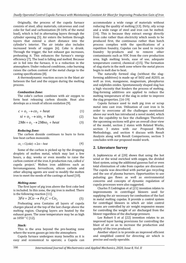
Positioning of the control valve is obtained based on the feedback given by Nonlinear Model Parameterized Predictive Controller to the microcontroller by comparing the reference value with the obtained value so as to reduce the complexity of microcontroller and give an accurate.
Figure 2: Dually Operated Control furnace
Model
The air blast allowed initially to furnace is monitored using oxygen and temperature sensor and the monitored value is compared with reference value and then according to that positioning of valve is controlled for maintaining constant air blast for adhering required oxygen content and to obtain a constant blast volume as well as blast temperature. Hence constant value of all this parameters will lead to give a stable melting rate and superheating rate. Further this melting rate and superheating rate is being feed backed to nonlinear controller so based on that our controller provides a predictions value to maintain stable melting rate and superheating rate by maintaining input air blast constant.
3.1. Cupola furnace
The cupola is a very complex dynamical system.
Unfortunately, a complete first-principle cupola model is not available to date. Accurate process modeling requires careful consideration of the principles of chemical and physics. Nevertheless, over forty coupled nonlinear differential equations (in space) as well as numerous algebraic relations describing stoichiometric and other relationships are the most detailed model available. The key points in this paper are the air blast inlet control for cupola furnace for their productivity gain. The results and future aspects can be fetched after the following details so far. Air blast inlet control for cupola furnace in our work illustrates two methods:
1) Manually operated 2) Automatic operated
3.1.1. Manually operated Manually Operated Mechanism states with an
effective method to control the air flow rate of an inverter driven blower.
Assuming the friction losses of a centrifugal blower andthe duct work connecting to it are negligible, and the blower is driven directly by a motor, then the relationship between the motor
shaft torque and the blower cage speed under different loading conditions, but with the same air flow rate, can be derived from the basic laws for fan and blower as follows:
2
2
1
1
TT
, (6)
Above equation is known as control law where T is motor shaft torque, ω is the speed of the motor.
Above Equation which states that by maintaining the motor-torque-to-speed ratio constant we can obtain a constant air flow rate at the blower outlet. Note that the control law can be obtained by several methods such as space vector pulse width modulation or brushless dc drives.
3.1.2 Space vector pulse width modulation
Space Vector Pulse Width Modulation (SVPWM) is a modulation that converts the controller's peripheral phase voltage relationship of Pulse Width Modulation (PWM) into time / duty cycles. SVPWM refers to a special sequence of the upper three power switches of a three-phase inverter.
It is a type of technique of modulation used by the reference vector to adjust the width of the pulse. In this technique, in a two-dimensional voltage domain, all possible switching states are represented as vectors, obtained by transforming three phase-dependent vectors into three phase-independent vectors. Ideally, the sampling frequency should be infinity, but the frequency of sampling is limited by the device's turn-on and turn-off times. The maximum sampling frequency for minimum total harmonic distortion is therefore selected.
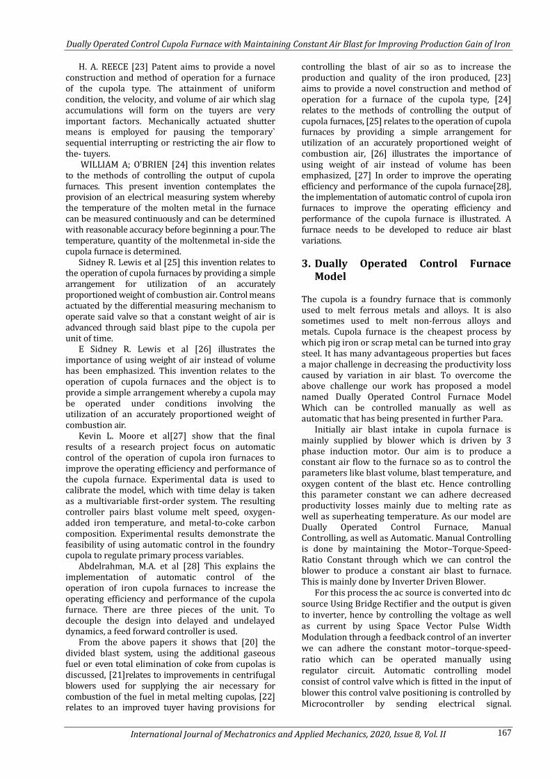
3.1.2.1 Principle of SVPWM Figure shows the circuit of a typical three-phase
voltage source inverter. This is made up of, A three phase supply (L1, L2, and L3) and a
three-phased diode rectifier (D1to D6). A DC-link capacitor (C) for energy storage and
voltage stabilization An inverter bridge with six transistors (T1 to T6) Three output terminals and a star-connected
(ungrounded) induction machine equivalent (U, V, W).
Figure 3: Three Phases Voltage Source PWM Inverter
First, it is possible to simplify the voltage of the
DC-link so that it is constant. It normally varies with load, but not so much during the time frames set out
Dually Operated Control Cupola Furnace with Maintaining Constant Air Blast for Improving Production Gain of Iron
International Journal of Mechatronics and Applied Mechanics, 2020, Issue 8, Vol. II 169
in this article. The source and diode rectifier for the remainder of the article will therefore not be shown.
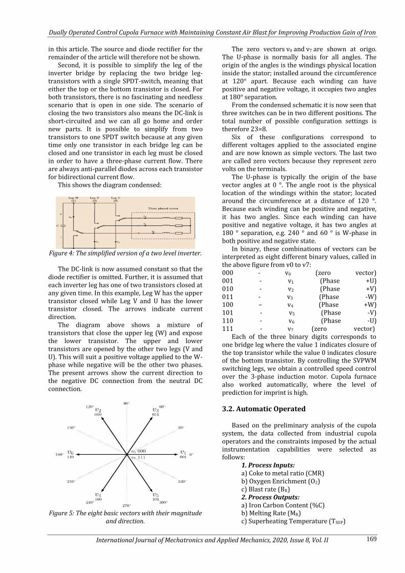
Second, it is possible to simplify the leg of the inverter bridge by replacing the two bridge leg-transistors with a single SPDT-switch, meaning that either the top or the bottom transistor is closed. For both transistors, there is no fascinating and needless scenario that is open in one side. The scenario of closing the two transistors also means the DC-link is short-circuited and we can all go home and order new parts. It is possible to simplify from two transistors to one SPDT switch because at any given time only one transistor in each bridge leg can be closed and one transistor in each leg must be closed in order to have a three-phase current flow. There are always anti-parallel diodes across each transistor for bidirectional current flow.
This shows the diagram condensed:
Figure 4: The simplified version of a two level inverter.
The DC-link is now assumed constant so that the
diode rectifier is omitted. Further, it is assumed that each inverter leg has one of two transistors closed at any given time. In this example, Leg W has the upper transistor closed while Leg V and U has the lower transistor closed. The arrows indicate current direction.
The diagram above shows a mixture of transistors that close the upper leg (W) and expose the lower transistor. The upper and lower transistors are opened by the other two legs (V and U). This will suit a positive voltage applied to the W-phase while negative will be the other two phases. The present arrows show the current direction to the negative DC connection from the neutral DC connection.
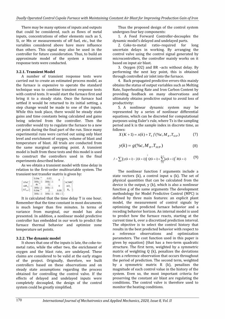
Figure 5: The eight basic vectors with their magnitude
and direction.
The zero vectors v0 and v7 are shown at origo. The U-phase is normally basis for all angles. The origin of the angles is the windings physical location inside the stator; installed around the circumference at 120° apart. Because each winding can have positive and negative voltage, it occupies two angles at 180° separation.
From the condensed schematic it is now seen that three switches can be in two different positions. The total number of possible configuration settings is therefore 23=8.
Six of these configurations correspond to different voltages applied to the associated engine and are now known as simple vectors. The last two are called zero vectors because they represent zero volts on the terminals.
The U-phase is typically the origin of the base vector angles at 0 °. The angle root is the physical location of the windings within the stator; located around the circumference at a distance of 120 °. Because each winding can be positive and negative, it has two angles. Since each winding can have positive and negative voltage, it has two angles at 180 ° separation, e.g. 240 ° and 60 ° is W-phase in both positive and negative state.
In binary, these combinations of vectors can be interpreted as eight different binary values, called in the above figure from v0 to v7: 000 - v0 (zero vector) 001 - v1 (Phase +U) 010 - v2 (Phase +V) 011 - v3 (Phase -W) 100 – v4 (Phase +W) 101 - v5 (Phase -V) 110 - v6 (Phase -U) 111 - v7 (zero vector)
Each of the three binary digits corresponds to one bridge leg where the value 1 indicates closure of the top transistor while the value 0 indicates closure of the bottom transistor. By controlling the SVPWM switching legs, we obtain a controlled speed control over the 3-phase induction motor. Cupola furnace also worked automatically, where the level of prediction for imprint is high.
3.2. Automatic Operated
Based on the preliminary analysis of the cupola
system, the data collected from industrial cupola operators and the constraints imposed by the actual instrumentation capabilities were selected as follows:
1. Process Inputs: a) Coke to metal ratio (CMR) b) Oxygen Enrichment (O2) c) Blast rate (BR) 2. Process Outputs: a) Iron Carbon Content (%C) b) Melting Rate (MR) c) Superheating Temperature (TSUP)
Dually Operated Control Cupola Furnace with Maintaining Constant Air Blast for Improving Production Gain of Iron
International Journal of Mechatronics and Applied Mechanics, 2020, Issue 8, Vol. II 170
There may be many options of inputs and outputs that could be considered, such as flows of metal inputs, concentrations of other elements such as S, Si, or Mn or measurements of off fuel, etc., but the variables considered above have more influence than others. This signal may also be used in the controller for future consideration. Thus, to build an approximate model of the system a transient response tests were conducted.
3.2.1. Transient Model
A number of transient response tests were carried out to create an estimated process model, as the furnace is expensive to operate the standard technique was to combine transient response tests with control tests. It would start the furnace first and bring it to a steady state. Once the furnace had settled it would be returned to its initial setting, a step change would be made to one of the inputs. While this took place, there would be steady state gains and time constants being calculated and gains being selected from the controller. Then the controller would try to regulate the furnace to a new set point during the final part of the run. Since many experimental runs were carried out using only blast level and enrichment of oxygen, volume of blast and temperature of blast. All trials are conducted from the same marginal operating point. A transient model is built from these tests and this model is used to construct the controllers used in the final experiments described below.
As we obtain a transient model with time delay in relation to the first-order multivariable system. The transient test transfer matrix is given by:
RTs
Ts
Ts
SUP
R
B
O
CMR
sss
ess
ess
e
T
M
C
2
160
08.0
1300
2
1300
04.0
01300
12
1300
4
01300
03.0
1300
04.0
%
It is calculated that the time delay T is one hour. Remember that the time constant in most documents is much longer than five minutes. In terms of variance from marginal, our model has also presented. In addition, a nonlinear model predictive controller has embedded in our work to predict the furnace thermal behavior and optimize zone temperature set points.
3.2.2. The dynamic model
It shows that one of the inputs is late, the coke-to-metal ratio, while the other two, the enrichment of oxygen and the blast rate, are undelayed. These claims are considered to be valid at the early stages of the project. Originally, therefore, we built controllers based on these observations and on steady state assumptions regarding the process obtained for controlling the control valve. If the effects of delayed and undelayed inputs were completely decoupled, the design of the control system could be greatly simplified.
Thus the proposed design of the control system undergoes four key components:
1. A Feed Forward Controller-decouples the dynamic model's delayed and undelayed parts.
2. Coke-to-metal ratio–required for long uncertain delays in working. By arranging the control valve using the control signal generated by microcontrollers, the controller mainly works on it based on input air blast.
3. Oxygen (O2) and BR –acts without delay. By performing the next key point, this is obtained through controlled air inlet into the furnace.
4. Back propagated predictive errors-this mainly obtains the status of output variables such as Melting Rate, Superheating Rate and Iron Carbon Content by providing feedback on many observations and ultimately obtains predictive output to avoid loss of productivity:
5. A nonlinear dynamic system may be represented by a series of nonlinear differential equations, which can be discreted for computational purposes using Euler's rule, where Ts is the sampling period and k is the sample index in discrete time, as follows:
),,(%)()1( SUPRS TMcfTkxKX (7)
),,(%)( SUPR TMcgky (8)
1
0
2
2
)()()())()((m
i
ikRikuikQikyikyJ (9)
The nonlinear function f arguments include a state vectorx (k), a control input u (k). The set of physical quantities that can be calculated from the device is the output, y (k), which is also a nonlinear function g of the same arguments The development methodology for Model Predictive Control (MPC) is defined by three main features: an explicit plant model, the measurement of control signals by optimizing the predicted furnace behavior and a receding behavior horizon. An internal model is used to predict how the furnace reacts, starting at the current time k, over a discretized prediction interval. The objective is to select the control history that results in the best predicted behavior with respect to a reference observations and optimization parameters. The cost function used in this paper is given by equation) (that has a two-term quadratic structure. The first term, weighted by a symmetric matrix of weighting Q (k), penalizes the deviations from a reference observation that occurs throughout the period of prediction. The second term, weighted by a symmetric matrix R (k), penalizes the magnitude of each control value in the history of the system. Even so, the most important criteria for preserving the constant air blast are regulating the conditions. The control valve is therefore used to monitor the heating conditions.
Dually Operated Control Cupola Furnace with Maintaining Constant Air Blast for Improving Production Gain of Iron
International Journal of Mechatronics and Applied Mechanics, 2020, Issue 8, Vol. II 171
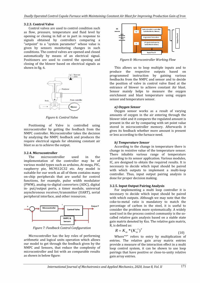
3.2.3. Control Valve Control valves are used to control condition such
as flow, pressure, temperature and fluid level by opening or closing in full or in part in response to signals obtained by controllers comparing a "setpoint" to a "system parameter" whose value is given by sensors monitoring changes in such conditions. The control valves are opened and closed automatically by means of an electrical signal. Positioners are used to control the opening and closing of the blower based on electrical signals as shown in fig. 6.
Figure 6: Control Valve
Positioning of Valve is controlled using
microcontroller by getting the feedback from the NMPC controller. Microcontroller takes the decision by analyzing the NMPC feedback and produces the require electrical signals for obtaining constant air blast so as to achieve the output.
3.2.4. Microcontroller
The microcontroller used in the implementation of the controller may be of various model types such as arduino, At mega, PIC, raspberry pie, MC9S12C32 etc. Any model is suitable for our work as all of them contains many on-chip peripherals that are useful for control functions, for example, pulse width modulator (PWM), analog-to-digital converters (ADC), digital in- put/output ports, a timer module, universal asynchronous receiver/transmitter (UART), serial peripheral interface, and other resources.
Figure 7: Feedback Control Configuration
Microcontroller has the key roles of performing
arithmetic and logical units operation which allows our model to get through the feedback given by the NMPC and Sensors, that reduce the complexity of microcontroller and list with an comparable results as shown in below figure:
Figure 8: Microcontroller Working Flow
This allows us to loop multiple inputs and to
produce the respective outputs based on programmed instruction by gaining various feedbacks from the NMPC and sensor and to decide the position of valve in control valve fixed at the entrance of blower to achieve constant Air blast. Sensor mainly helps to measure the oxygen enrichment and blast temperature using oxygen sensor and temperature sensor.
a) Oxygen Sensor Oxygen sensor works as a result of varying
amounts of oxygen in the air entering through the blower inlet and it compares the regulated amount is present in the air by comparing with set point value stored in microcontroller memory. Afterwards it gives its feedback whether more amount is present or less according to the furnace need.
b) Temperature Sensor According to the change in temperature there is
change in resistive value of the temperature sensor. There inhabits various range of temperature according to its sensor application. Various modules, IC, are designed to obtain the required results. It is necessary to decide which input should be paired with which outputs to implement a multi-loop controller. Thus, input output pairing analysis is done for proper decision making.
3.2.5. Input Output Pairing Analysis
For implementing a multi loop controller it is necessary to decide which input should be paired with which outputs. Although we may note that the coke-to-metal ratio is mandatory to match the percentage of carbon in the steel, it is useful to consider the problem more systematically. A widely used tool in the process control community is the so-called relative gain analysis based on a stable state gain matrix denoted by Kss. The relative gain matrix, R, is defined as:
T
ssss KKR )(* 1 (10)
Where"*" refers to entry by multiplication of entries. The relative gain array matrix entries provide a measure of the interaction effect in a multi loop control system, it can be shown to use loop pairings that have positive or close-to-unity relative gain array entries.
Dually Operated Control Cupola Furnace with Maintaining Constant Air Blast for Improving Production Gain of Iron
International Journal of Mechatronics and Applied Mechanics, 2020, Issue 8, Vol. II 172
Steady state gain matrix for cupola furnace is defined by:
RSUP
R
B
O
CMR
T
M
C
2
08.022
0124
003.004.0%
From this we can compute the relative gain array matrix:
122
03.13.
03.3.1
R
This matrix makes it clear that, from the perspective of loop gain interactions, the following loop pairings are used and implemented by controller.
1. Iron Carbon Content (%C) 2. Melting Rate (MR) 3. Superheating Temperature (TSUP)
3.3 Controller Implementation
Four points should be noted: 1. In addition, the control system is a cascade
controller, where the controllers mentioned here are actually used to drive the set points for the controllers at the instrument stage. The only exception to this is the proportion of coke to iron. This loop was implemented as follows in a semi-automatic mode. These changes were shown on the monitor and then relayed to peroneal charging of the cupola via two-way radio.
2. Due to hardware and data acquisition constraints there were a number of different sampling times in the actual implementation.
3. AH of the key output signals suffered from noise problems. As a result, it was necessary to use various filters in the control system. For “/Carbon and temperature the filters were simple averaging filters. For temperature we averaged and also applied hard limiters and standard deviation filters to reject measurements that were too far out of range to be true. This was necessary because we were using an unreliable pyrometer to measure the temperature of the molten iron. Getting a good melt rate measurement was a more challenging problem. This was because the only available measurement was the actually weight of iron.
Thus it was necessary to differentiate the measurement of weight to get melt rate (weight per unit time). The technique used to do this was to calculate to a fixed number of weight readings a minimum square fit of a line. The melt rate is the slope of this line, which has also been passed through hard limiters and standard deviation filters. The final version of the paper will include a more complete description of the different signal filters.
4. Actual gains from the controller were selected through simulation. This was done using standard root locus-based design and then checked via simulation. Closed-loop poles were selected so that in the simulated experiments there was no overshoot in any signals. The resulting controller had the form:
=
where E denotes the error signal. Thus, above discussion shows that the cupola
furnace for producing iron can operate either manually and automatic for high predictive analysis. Therefore, our proposed method obtains high productivity gain for producing iron by maintaining constant air blast.
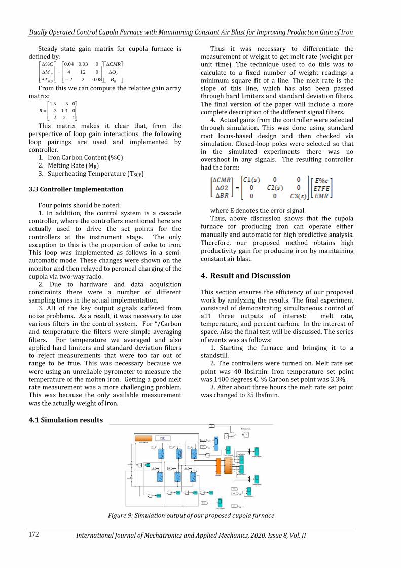
4. Result and Discussion This section ensures the efficiency of our proposed work by analyzing the results. The final experiment consisted of demonstrating simultaneous control of a11 three outputs of interest: melt rate, temperature, and percent carbon. In the interest of space. Also the final test will be discussed. The series of events was as follows:
1. Starting the furnace and bringing it to a standstill.
2. The controllers were turned on. Melt rate set point was 40 Ibslrnin. Iron temperature set point was 1400 degrees C. % Carbon set point was 3.3%.
3. After about three hours the melt rate set point was changed to 35 Ibsfmin.
4.1 Simulation results
Figure 9: Simulation output of our proposed cupola furnace
Dually Operated Control Cupola Furnace with Maintaining Constant Air Blast for Improving Production Gain of Iron
International Journal of Mechatronics and Applied Mechanics, 2020, Issue 8, Vol. II 173
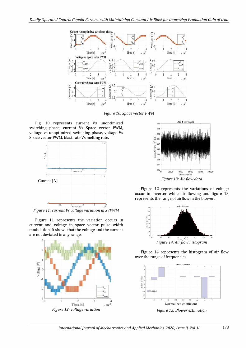
Figure 10: Space vector PWM
Fig. 10 represents current Vs unoptimized
switching phase, current Vs Space vector PWM, voltage vs unoptimized switching phase, voltage Vs Space vector PWM, blast rate Vs melting rate.
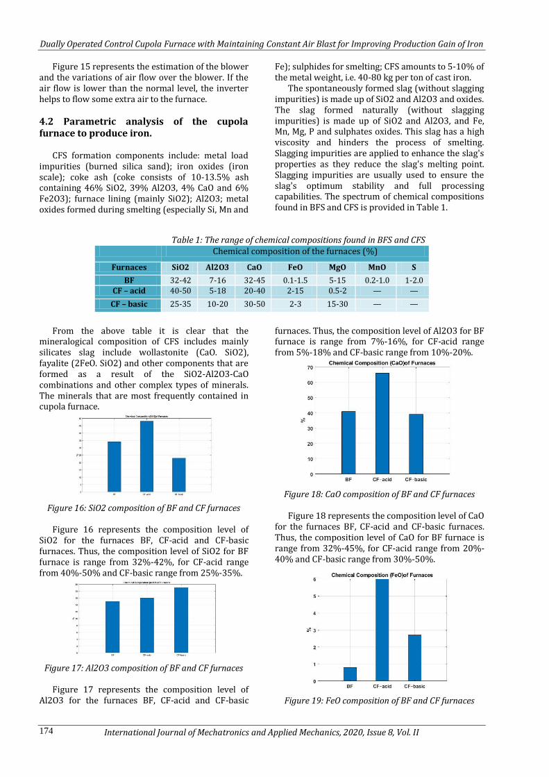
Figure 11: current Vs voltage variation in SVPWM
Figure 11 represents the variation occurs in
current and voltage in space vector pulse width modulation. It shows that the voltage and the current are not deviated in any range.
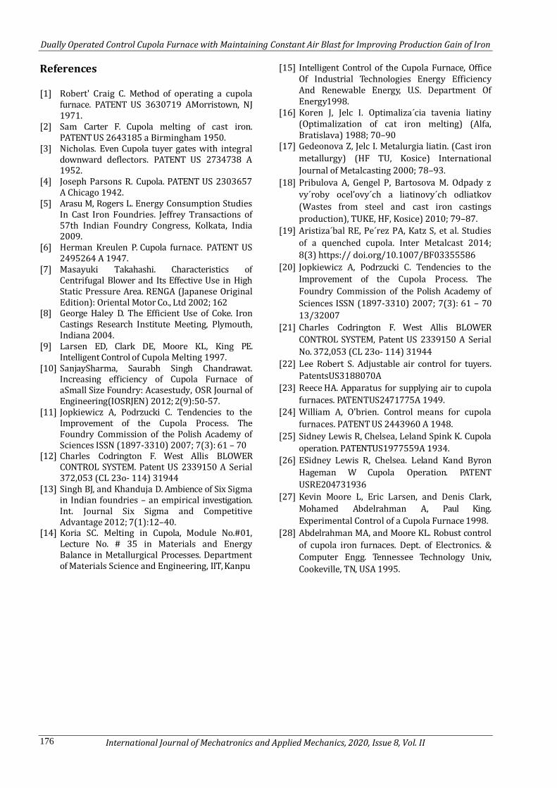
Figure 12: voltage variation
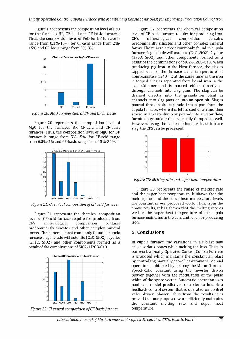
Figure 13: Air flow data
Figure 12 represents the variations of voltage
occur in inverter while air flowing and figure 13 represents the range of airflow in the blower.
Figure 14: Air flow histogram
Figure 14 represents the histogram of air flow
over the range of frequencies
Figure 15: Blower estimation
Normalized coefficient
Current [A]
Dually Operated Control Cupola Furnace with Maintaining Constant Air Blast for Improving Production Gain of Iron
International Journal of Mechatronics and Applied Mechanics, 2020, Issue 8, Vol. II 174
Figure 15 represents the estimation of the blower and the variations of air flow over the blower. If the air flow is lower than the normal level, the inverter helps to flow some extra air to the furnace.
4.2 Parametric analysis of the cupola furnace to produce iron.
CFS formation components include: metal load
impurities (burned silica sand); iron oxides (iron scale); coke ash (coke consists of 10-13.5% ash containing 46% SiO2, 39% Al2O3, 4% CaO and 6% Fe2O3); furnace lining (mainly SiO2); Al2O3; metal oxides formed during smelting (especially Si, Mn and
Fe); sulphides for smelting; CFS amounts to 5-10% of the metal weight, i.e. 40-80 kg per ton of cast iron.
The spontaneously formed slag (without slagging impurities) is made up of SiO2 and Al2O3 and oxides. The slag formed naturally (without slagging impurities) is made up of SiO2 and Al2O3, and Fe, Mn, Mg, P and sulphates oxides. This slag has a high viscosity and hinders the process of smelting. Slagging impurities are applied to enhance the slag's properties as they reduce the slag's melting point. Slagging impurities are usually used to ensure the slag's optimum stability and full processing capabilities. The spectrum of chemical compositions found in BFS and CFS is provided in Table 1.
Table 1: The range of chemical compositions found in BFS and CFS Chemical composition of the furnaces (%)
Furnaces SiO2 Al2O3 CaO FeO MgO MnO S
BF 32-42 7-16 32-45 0.1-1.5 5-15 0.2-1.0 1-2.0 CF – acid 40-50 5-18 20-40 2-15 0.5-2 — —
CF – basic 25-35 10-20 30-50 2-3 15-30 — —
From the above table it is clear that the
mineralogical composition of CFS includes mainly silicates slag include wollastonite (CaO. SiO2), fayalite (2FeO. SiO2) and other components that are formed as a result of the SiO2-Al2O3-CaO combinations and other complex types of minerals. The minerals that are most frequently contained in cupola furnace.
Figure 16: SiO2 composition of BF and CF furnaces
Figure 16 represents the composition level of
SiO2 for the furnaces BF, CF-acid and CF-basic furnaces. Thus, the composition level of SiO2 for BF furnace is range from 32%-42%, for CF-acid range from 40%-50% and CF-basic range from 25%-35%.
Figure 17: Al2O3 composition of BF and CF furnaces
Figure 17 represents the composition level of
Al2O3 for the furnaces BF, CF-acid and CF-basic
furnaces. Thus, the composition level of Al2O3 for BF furnace is range from 7%-16%, for CF-acid range from 5%-18% and CF-basic range from 10%-20%.
Figure 18: CaO composition of BF and CF furnaces
Figure 18 represents the composition level of CaO
for the furnaces BF, CF-acid and CF-basic furnaces. Thus, the composition level of CaO for BF furnace is range from 32%-45%, for CF-acid range from 20%-40% and CF-basic range from 30%-50%.
Figure 19: FeO composition of BF and CF furnaces
Dually Operated Control Cupola Furnace with Maintaining Constant Air Blast for Improving Production Gain of Iron
International Journal of Mechatronics and Applied Mechanics, 2020, Issue 8, Vol. II 175
Figure 19 represents the composition level of FeO for the furnaces BF, CF-acid and CF-basic furnaces. Thus, the composition level of FeO for BF furnace is range from 0.1%-15%, for CF-acid range from 2%-15% and CF-basic range from 2%-3%.
Figure 20: MgO composition of BF and CF furnaces
Figure 20 represents the composition level of
MgO for the furnaces BF, CF-acid and CF-basic furnaces. Thus, the composition level of MgO for BF furnace is range from 5%-15%, for CF-acid range from 0.5%-2% and CF-basic range from 15%-30%.
Figure 21: Chemical composition of CF-acid furnace
Figure 21 represents the chemical composition
level of CF-acid furnace require for producing iron. CF's mineralogical composition contains predominantly silicates and other complex mineral forms. The minerals most commonly found in cupola furnace slag include will astonite (CaO. SiO2), fayalite (2FeO. SiO2) and other components formed as a result of the combinations of SiO2-Al2O3-CaO.
Figure 22: Chemical composition of CF-basic furnace
Figure 22 represents the chemical composition level of CF-basic furnace require for producing iron. CF's mineralogical composition contains predominantly silicates and other complex mineral forms. The minerals most commonly found in cupola furnace slag include will astonite (CaO. SiO2), fayalite (2FeO. SiO2) and other components formed as a result of the combinations of SiO2-Al2O3-CaO. When producing pig iron in the blast furnace, the slag is tapped out of the furnace at a temperature of approximately 1540 ° C at the same time as the iron is tapped. Slag is separated from liquid iron in the slag skimmer and is poured either directly or through channels into slag pans. The slag can be drained directly into the granulation plant in channels, into slag pans or into an open pit. Slag is poured through the tap hole into a pan from the cupola furnace, where it is left to cool down and then stored in a waste dump or poured into a water flow, forming a granulate that is usually dumped as well. However, using the same methods as blast furnace slag, the CFS can be processed.
Figure 23: Melting rate and super heat temperature
Figure 23 represents the range of melting rate
and the super heat temperature. It shows that the melting rate and the super heat temperature levels are constant in our proposed work. Thus, from the above results, it has shown that the melting rate as well as the super heat temperature of the cupola furnace maintains in the constant level for producing iron.
5. Conclusions In cupola furnace, the variations in air blast may cause serious issues while melting the iron. Thus, in our work a Dually Operated Control Cupola Furnace is proposed which maintains the constant air blast by controlling manually as well as automatic. Manual operation is obtained by keeping the Motor-Torque-Speed-Ratio constant using the inverter driven blower together with the modulation of the pulse width of the space vector. Automatic operation uses nonlinear model predictive controller to inhabit a feedback control system that is operated on control valve driven blower. Thus from the results it is proved that our proposed work efficiently maintains the constant melting rate and super heat temperature.
Dually Operated Control Cupola Furnace with Maintaining Constant Air Blast for Improving Production Gain of Iron
International Journal of Mechatronics and Applied Mechanics, 2020, Issue 8, Vol. II 176
References [1] Robert' Craig C. Method of operating a cupola
furnace. PATENT US 3630719 AMorristown, NJ 1971.
[2] Sam Carter F. Cupola melting of cast iron. PATENT US 2643185 a Birmingham 1950.
[3] Nicholas. Even Cupola tuyer gates with integral downward deflectors. PATENT US 2734738 A 1952.
[4] Joseph Parsons R. Cupola. PATENT US 2303657 A Chicago 1942.
[5] Arasu M, Rogers L. Energy Consumption Studies In Cast Iron Foundries. Jeffrey Transactions of 57th Indian Foundry Congress, Kolkata, India 2009.
[6] Herman Kreulen P. Cupola furnace. PATENT US 2495264 A 1947.
[7] Masayuki Takahashi. Characteristics of Centrifugal Blower and Its Effective Use in High Static Pressure Area. RENGA (Japanese Original Edition): Oriental Motor Co., Ltd 2002; 162
[8] George Haley D. The Efficient Use of Coke. Iron Castings Research Institute Meeting, Plymouth, Indiana 2004.
[9] Larsen ED, Clark DE, Moore KL, King PE. Intelligent Control of Cupola Melting 1997.
[10] SanjaySharma, Saurabh Singh Chandrawat. Increasing efficiency of Cupola Furnace of aSmall Size Foundry: Acasestudy, OSR Journal of Engineering(IOSRJEN) 2012; 2(9):50-57.
[11] Jopkiewicz A, Podrzucki C. Tendencies to the Improvement of the Cupola Process. The Foundry Commission of the Polish Academy of Sciences ISSN (1897-3310) 2007; 7(3): 61 – 70
[12] Charles Codrington F. West Allis BLOWER CONTROL SYSTEM. Patent US 2339150 A Serial 372,053 (CL 23o- 114) 31944
[13] Singh BJ, and Khanduja D. Ambience of Six Sigma in Indian foundries – an empirical investigation. Int. Journal Six Sigma and Competitive Advantage 2012; 7(1):12–40.
[14] Koria SC. Melting in Cupola, Module No.#01, Lecture No. # 35 in Materials and Energy Balance in Metallurgical Processes. Department of Materials Science and Engineering, IIT, Kanpu
[15] Intelligent Control of the Cupola Furnace, Office Of Industrial Technologies Energy Efficiency And Renewable Energy, U.S. Department Of Energy 1998.
[16] Koren J, Jelc I. Optimaliza´cia tavenia liatiny (Optimalization of cat iron melting) (Alfa, Bratislava) 1988; 70–90
[17] Gedeonova Z, Jelc I. Metalurgia liatin. (Cast iron
metallurgy) (HF TU, Kosice) International
Journal of Metalcasting 2000; 78–93.
[18] Pribulova A, Gengel P, Bartosova M. Odpady z
vy´roby ocel’ovy´ch a liatinovy´ch odliatkov
(Wastes from steel and cast iron castings
production), TUKE, HF, Kosice) 2010; 79–87.
[19] Aristiza´bal RE, Pe´rez PA, Katz S, et al. Studies
of a quenched cupola. Inter Metalcast 2014;
8(3) https:// doi.org/10.1007/BF03355586
[20] Jopkiewicz A, Podrzucki C. Tendencies to the
Improvement of the Cupola Process. The
Foundry Commission of the Polish Academy of
Sciences ISSN (1897-3310) 2007; 7(3): 61 – 70
13/32007
[21] Charles Codrington F. West Allis BLOWER
CONTROL SYSTEM, Patent US 2339150 A Serial
No. 372,053 (CL 23o- 114) 31944
[22] Lee Robert S. Adjustable air control for tuyers.
PatentsUS3188070A
[23] Reece HA. Apparatus for supplying air to cupola
furnaces. PATENTUS2471775A 1949.
[24] William A, O'brien. Control means for cupola
furnaces. PATENT US 2443960 A 1948.
[25] Sidney Lewis R, Chelsea, Leland Spink K. Cupola
operation. PATENTUS1977559A 1934.
[26] ESidney Lewis R, Chelsea. Leland Kand Byron
Hageman W Cupola Operation. PATENT
USRE204731936
[27] Kevin Moore L, Eric Larsen, and Denis Clark,
Mohamed Abdelrahman A, Paul King.
Experimental Control of a Cupola Furnace 1998.
[28] Abdelrahman MA, and Moore KL. Robust control
of cupola iron furnaces. Dept. of Electronics. &
Computer Engg. Tennessee Technology Univ.,
Cookeville, TN, USA 1995.


