Westpoint Building 2 | De Brauwweg 60 | 3125 AE Schiedam | The Netherlands | www.kci.nl | [email protected]
Dubai-I “Voor en Door Staalconstructeurs”
23-11-2016 ir. R. van der Geer & ir. S. Maljaars

KCI Company profile
• Founded in 1987 • Main markets are
– Oil & Gas – Renewables – Equipment – Wheels
• ISO 9001 certified • FPAL registered no. 10049367 • Part of Oceanteam group
“It’s our drive to create the best solutions for our customers assets”
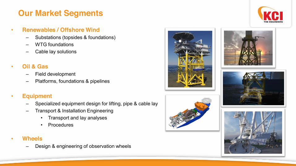
Our Market Segments
• Renewables / Offshore Wind – Substations (topsides & foundations) – WTG foundations – Cable lay solutions
• Oil & Gas
– Field development – Platforms, foundations & pipelines
• Equipment
– Specialized equipment design for lifting, pipe & cable lay – Transport & Installation Engineering
• Transport and lay analyses • Procedures
• Wheels
– Design & engineering of observation wheels

General Project Info – Introduction
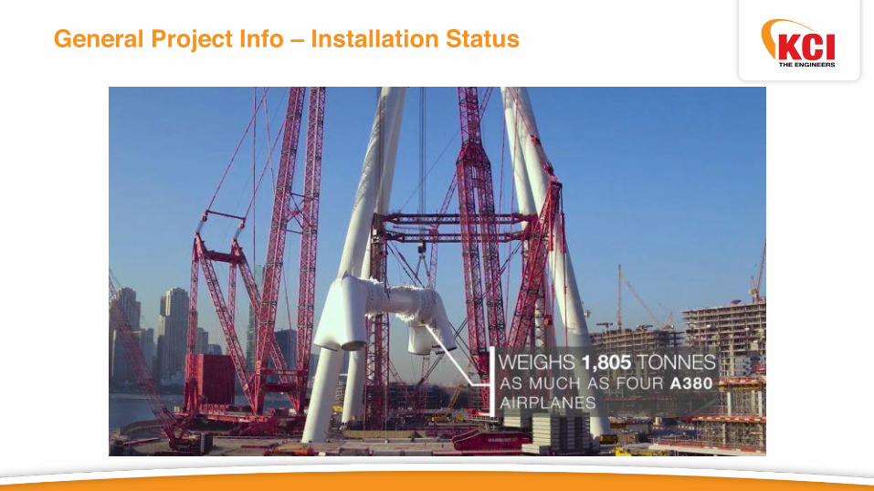
Key Figures: • Approx. 250m Top Elevation • 137.5m Spindle Elevation • 238m Rim Diameter • 48 Capsules (40p. Capacity Each) • 192 Spoke Cables • 4 Towers with Drive & Guide Units • Total Mass approx. 11,000mton

General Project Info – Project Location
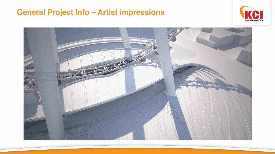
General Project Info – Artist impressions
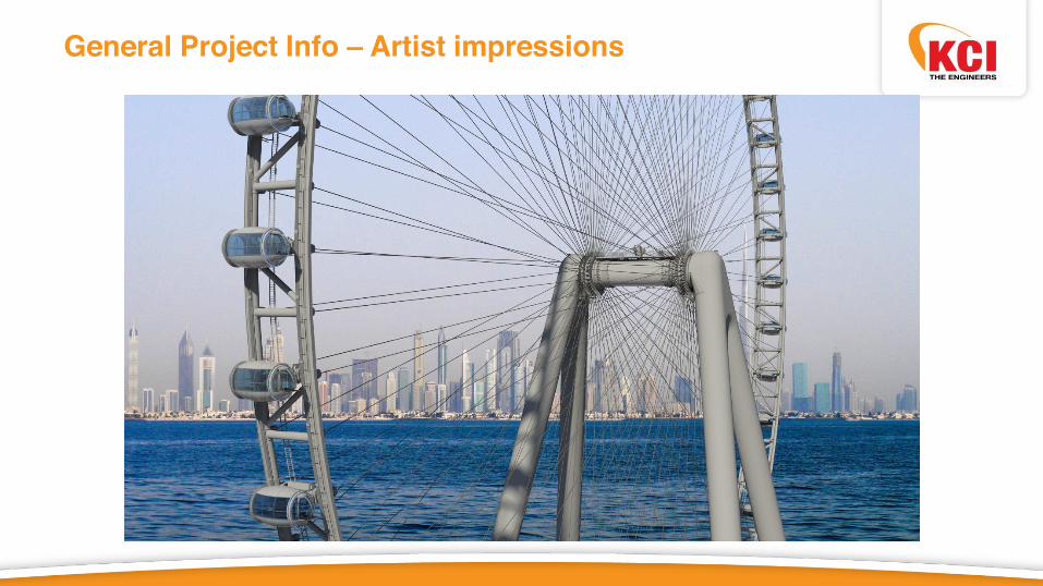
General Project Info – Artist impressions
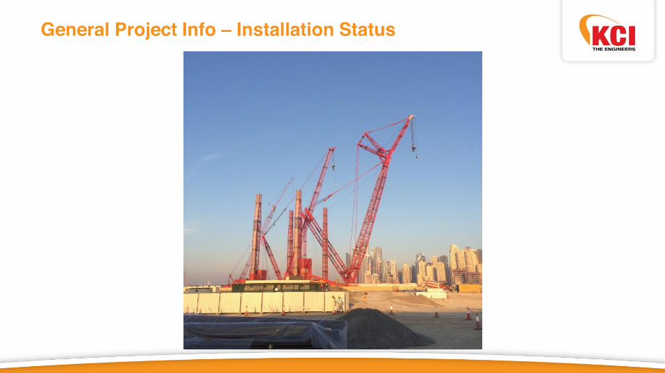
General Project Info – Installation Status
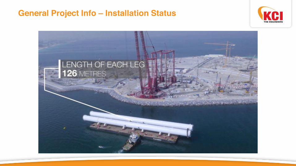
General Project Info – Installation Status

General Project Info – Installation Status

General Project Info – Installation Status

General Project Info – Installation Status
General Project Info – Installation Status

General Project Info – Installation Status

General Project Info – Installation Status

General Project Info – Installation Status

Specific Engineering & Design Topics
• Static Analyses - Wind Load • Dynamic Wind Response • ANSYS Post-Processing Routines • Static Wind Tunnel Tests • Dynamic Wind Tunnel Tests • Spectral Seismic Analyses • Seismic Time-History Analyses • Various Fatigue Analyses • Various Detailed Analyses • SCF Calculations • Capsule Design • Evacuation Strategy • Guide/Drive Unit Design • Storm Lock Design • Collector Gear Design • Temperature Effects • Rim Pushover Analyses • A-Frame Pushover Analyses • A-Frame Footing Design • Imperfections
• Installation Analyses • Bearing Design • Spoke Cable Design • Cable Socket Design • Bent Limiter Design • Cable Damper Design • Vortex Induced Vibrations • Tuned Mass Dampers • Bearing Replacement • Bearing Pad Exchange • Bearing Tests • Foundation Stiffness Variation • Various Sensitivity Studies • Restraint Tower Stiffness • Hub-Drive Design • Boarding Platform Gap Analyses • Cable Replacement Analyses • Accidental Spoke Cable Snap • ... Many More

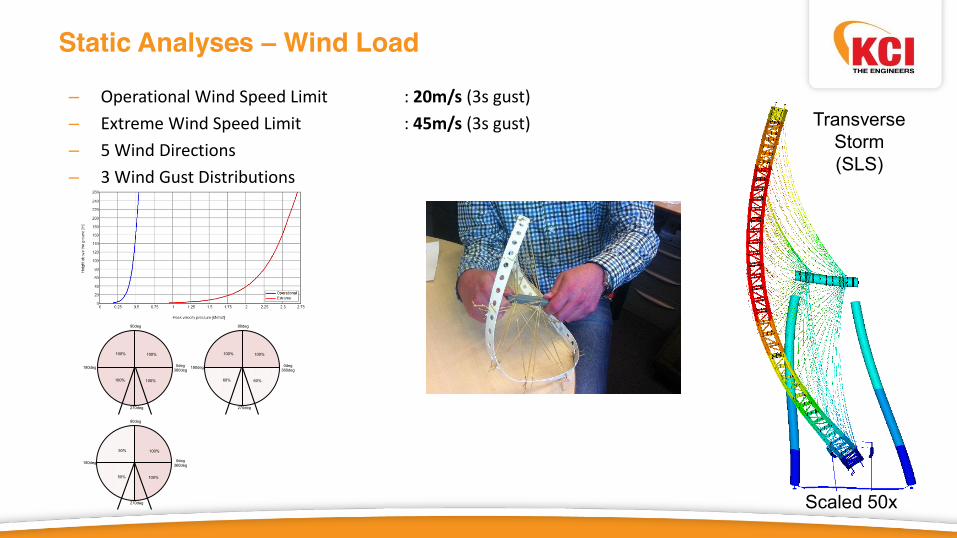
Static Analyses – Wind Load – Operational Wind Speed Limit : 20m/s (3s gust) – Extreme Wind Speed Limit : 45m/s (3s gust) – 5 Wind Directions – 3 Wind Gust Distributions
270deg
180deg
90deg
0deg 360deg
270deg
180deg
90deg
0deg 360deg
100% 100%
60% 60%
270deg
180deg
90deg
0deg 360deg
100% 100%
100% 100%
50% 100%
50% 100%
Transverse Storm (SLS)
Scaled 50x

Static Analyses – Monitored Parameters
Monitored Results with User-Defined ANSYS routines: • Cable Forces • Member UC’s • Tubular Joint UC’s • Bearing Loads • A-Frame Support Reactions • Drive & Guide Forces • Deflections
• Spindle • A-Frame Foundations • Rim • Capsules at Boarding Platform

Dynamic Wind Response
• Wind Response • Time History Analysis • DAF-factor • Human Comfort

Fatigue Analyses - Introduction
• Applied codes • Fatigue loadings • Applied methods • Calculation examples • Conclusions

Fatigue Analyses – Applied codes • Eurocode 3 - BS EN 1993-1-9:2005 • International Institute of Welding IIW - document IIW-1823-07 • DG-8-CIDECT - Design guide for circular and rectangular hollow sections welded joints under
fatigue loading • Several papers

Fatigue Analyses – Fatigue loadings
• Wheel rotation (gravitational force)
• Interaction between rim drive box
and drive and restraint system • Wind effect • Temperature effects • Seismic acitivity
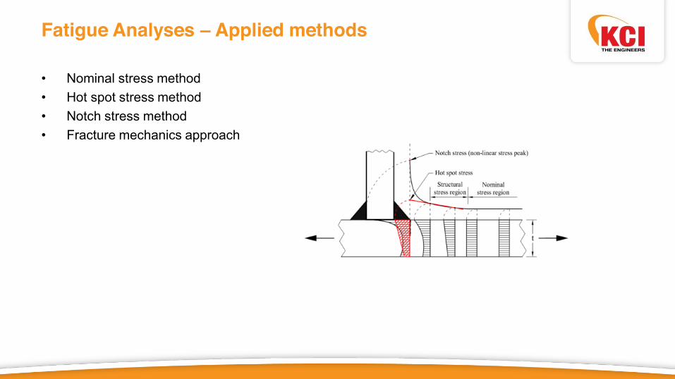
Fatigue Analyses – Applied methods • Nominal stress method • Hot spot stress method • Notch stress method • Fracture mechanics approach
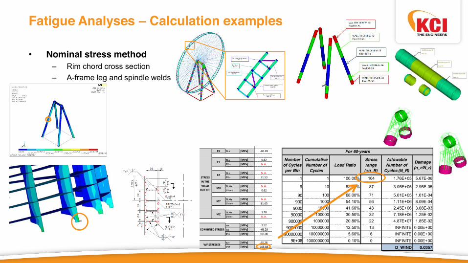
Fatigue Analyses – Calculation examples • Nominal stress method
– Rim chord cross section – A-frame leg and spindle welds
• Hot spot stress method – Rim chord tubular joints (CIDECT) – Local details in rim – Local details in A-frame and Brace – All welds in the Hubs
• Notch stress method – Conical spoke to rim joint – Weld details in rotating hubs
• Fracture mechanics approach
1(weld 3)
Steel type [-] 355Steel class [-] J2
t1 [mm] 25L1 [mm] 200.00a1 [mm] 7.07w1 [mm] 25
fu [MPa] 469
βw [-] 0.9γm2 [-] 1.25
Fx [N] -1.85E+05Fy [N] 2.33E+03Fz [N] 6.09E+04Mx [Nm] -2.18E+01My [Nm] -7.70E+03Mz [Nm] 1.60E+02
fw.u.d1 [MPa] 416.89fw.u.d2 [MPa] 337.68
FX τ1.x [MPa] -65.28
τ2.y [MPa] 0.82σ2.y [MPa] N.A.
τ2.z [MPa] N.A.σ2.z [MPa] 21.53
τ2.Mx [MPa] N.A.σ2.Mx [MPa] 0.62
τ2.My [MPa] N.A.σ2.My [MPa] 81.65
τ2.Mz [MPa] 1.70σ2.Mz [MPa] N.A.
τv1 [MPa] 2.52τv2 [MPa] -65.28σv1 [MPa] 103.80
τwf [MPa] 65.28σwf [MPa] 103.83
WF STRESSES
STRESS IN THE WELD
DUE TO:
FY
FZ
MX
MY
MZ
LOADS
VARIABLES
ALLOWABLE STRESS
COMBINED STRESS
WELD NUMBER
1 1 100.00% 104 1.76E+05 5.67E-06
9 10 83.30% 87 3.05E+05 2.95E-05
90 100 68.00% 71 5.61E+05 1.61E-04900 1000 54.10% 56 1.11E+06 8.09E-04
9000 10000 41.60% 43 2.45E+06 3.68E-0390000 100000 30.50% 32 7.18E+06 1.25E-02
900000 1000000 20.80% 22 4.87E+07 1.85E-029000000 10000000 12.50% 13 INFINITE 0.00E+00
90000000 100000000 5.60% 6 INFINITE 0.00E+009E+08 1000000000 0.10% 0 INFINITE 0.00E+00
D_WIND 0.0357
WIND FATIGUE DUE TO NORMAL STRESSFor 60-years
Number of Cycles per Bin
Cumulative Number of
CyclesLoad Ratio
Stress range (∆σ_R)
Allowable Number of
Cycles (N_R)
Damage (n_r/N_r)

Fatigue Analyses – Calculation examples • Nominal stress method
– Rim chord cross section – A-frame leg and spindle welds – Secondary steel attachments
• Hot spot stress method – Rim chord tubular joints (CIDECT) – Local details in rim – Local details in A-frame and Brace – All welds in the Hubs
• Notch stress method – Conical spoke to rim joint – Weld details in rotating hubs
• Fracture mechanics approach

Fatigue Analyses – Calculation examples • Nominal stress method
– Rim chord cross section – A-frame leg and spindle welds – Secondary steel attachments
• Hot spot stress method – Rim chord tubular joints (SCF functions
CIDECT) – Rim chord tubular joints (hot spot stress
according to CIDECT) – Local details in rim (hot spot stress
according IIW) – Weld details in A-frame and Brace – All welds in the Hubs
• Notch stress method – Conical spoke to rim joint – Weld details in rotating hubs
y(tangential)
x(radial)
z(axial)
y(tangential)
x(radial) z(axial)
Local Cylindrical CS w.r.t. Horizontal Brace
Local Cylindrical CS (CSYS 21) W.r.t. Diagonal Brace
0°
90°
180°
-90°
0°
90°
180°
-90°
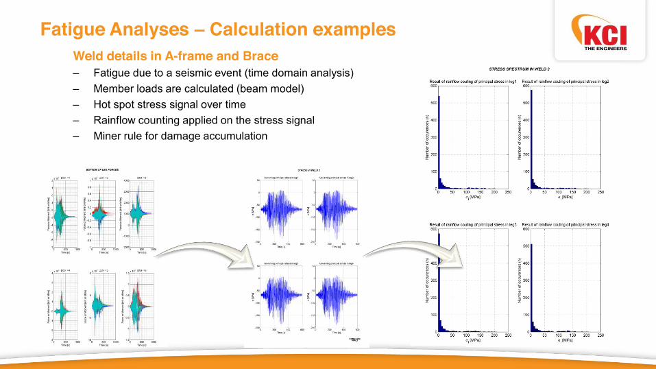
Fatigue Analyses – Calculation examples
Weld details in A-frame and Brace – Fatigue due to a seismic event (time domain analysis) – Member loads are calculated (beam model) – Hot spot stress signal over time – Rainflow counting applied on the stress signal – Miner rule for damage accumulation
• Hot spot stress method – Rim chord tubular joints (CIDECT) – Local details in rim – Local details in A-frame and Brace – All welds in the Hubs
• Notch stress method

Fatigue Analyses – Calculation examples • Nominal stress method
– Rim chord cross section – A-frame leg and spindle welds – Secondary steel attachments
• Hot spot stress method – Rim chord tubular joints (SCF functions
CIDECT) – Rim chord tubular joints (hot spot stress
according to CIDECT) – Local details in rim (hot spot stress
according IIW) – Weld details in A-frame and Brace – All welds in the rotating hubs
• Notch stress method – Conical spoke to rim joint – Weld details in rotating hubs

Fatigue Analyses – Calculation examples • Nominal stress method
– Rim chord cross section – A-frame leg and spindle welds – Secondary steel attachments
• Hot spot stress method – Rim chord tubular joints (SCF functions
CIDECT) – Rim chord tubular joints (hot spot stress
according to CIDECT) – Local details in rim (hot spot stress
according IIW) – Weld details in A-frame and Brace – All welds in the rotating hubsnubs
• Notch stress method – Conical spoke to rim joint

Fatigue Analyses – Calculation examples
Conical spoke to rim joint 1. Beam/shell model

Fatigue Analyses – Calculation examples
Conical spoke to rim joint 2. Solid sub-model
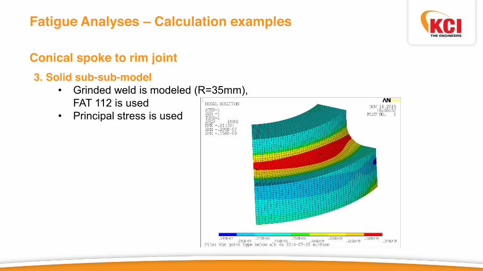
Fatigue Analyses – Calculation examples
Conical spoke to rim joint 3. Solid sub-sub-model • Grinded weld is modeled (R=35mm),
FAT 112 is used • Principal stress is used

Fatigue Analyses – Calculation examples • Nominal stress method
– Rim chord cross section – A-frame leg and spindle welds – Secondary steel attachments
• Hot spot stress method – Rim chord tubular joints (SCF functions
CIDECT) – Rim chord tubular joints (hot spot stress
according to CIDECT) – Local details in rim (hot spot stress
according IIW) – Weld details in A-frame and Brace – All welds in the rotating hubsnubs
• Notch stress method – Conical spoke to rim joint – Weld details in rotating hubs

Fatigue Analyses – Calculation examples
Weld details in rotating hubs 1. Shell model

Fatigue Analyses – Calculation examples
Weld details in rotating hubs 2. Solid sub-model

Fatigue Analyses – Calculation examples
Weld details in rotating hubs 3. Solid sub-sub-model
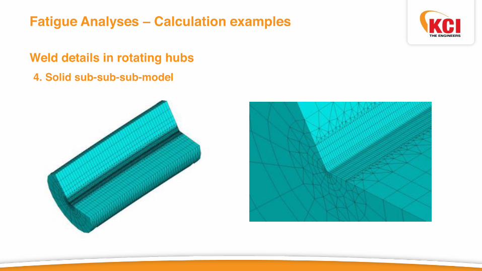
Fatigue Analyses – Calculation examples
Weld details in rotating hubs 4. Solid sub-sub-sub-model
Fatigue Analyses – Calculation examples
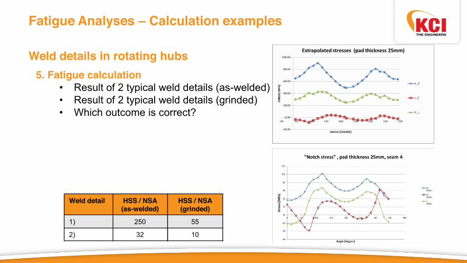
Weld details in rotating hubs 5. Fatigue calculation
• Result of 2 typical weld details (as-welded) • Result of 2 typical weld details (grinded) • Which outcome is correct?
Weld detail HSS / NSA (as-welded)
1) 250
2) 32
HSS / NSA (grinded)
55
10

Fatigue Analyses – Calculation examples • Nominal stress method
– Rim chord cross section – A-frame leg and spindle welds – Secondary steel attachments
• Hot spot stress method – Rim chord tubular joints (SCF functions
CIDECT) – Rim chord tubular joints (hot spot stress
according to CIDECT) – Local details in rim (hot spot stress
according IIW) – Weld details in A-frame and Brace – All welds in the rotating hub
• Notch stress method – Conical spoke to rim joint – Weld details in rotating hubs
• Fracture mechanics approach – Currently under consideration

Fatigue Analyses – Conclusions
• Nominal stress approach – Easy to use in beam/tubular structures – Relative quick lifetime estimation for standard weld
details
• Hot spot stress approach – Predict fatigue in geometric complex structures – Fatigue predictions in (relative) thin walled
structures – Be carrefull while using this method in very thick
walled structures
• Notch stress approach – Can be used at machined weld details – Can be used for non-categorized weld details

Thank you for your attention!