
Tokyo Institute of TechnologyMobile Communications Research Group
Dynamic Fractional CoMP
for Advanced Cellular Networks
Kei Sakaguchi
Tokyo Institute of Technology

Advanced Cellular Networks
Oct. 21, 2010 2
• Spatial spectrum sharing via Multi-User MIMO and Femto Cell
Multi-User MIMO
Femto cell
Relay
Base Station Cooperation
• Pathloss compensation via Relay
• Interference Management via Base Station Cooperation
Cell throughput improvement
User throughput improvement

Cell-edge Problem
Oct. 21, 2010 3
1H 2H
• Worst SINR due to high pathloss and strong interference from adjacent BS
• Reduced MIMO multiplexing gain due to low SINR
• Further degradation due to higher spatial correlation at BSs
Single Cell Single User MIMO
Spectral efficiency
BS1 BS2UE1 UE2

Base Station Cooperation
Oct. 21, 2010 4
Cooperation between adjacent BSs for interference management
Coordinated Scheduling / Beamforming Base Station Cooperation
BS2BS1 UE1
UE2
BS1 BS2UE1
UE2
• without data sharing
• with data sharing
→ Coordinated Scheduling / Beamforming
→ Base Station Cooperation MIMO (CoMP JT)
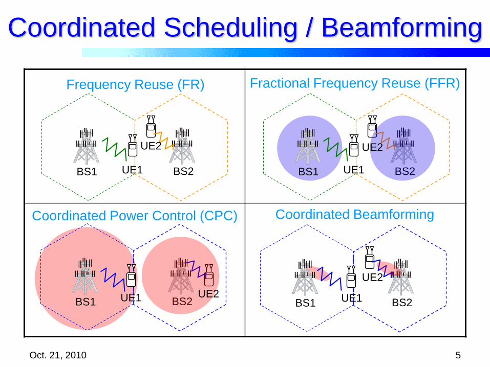
Coordinated Scheduling / Beamforming
Oct. 21, 2010 5
Frequency Reuse (FR) Fractional Frequency Reuse (FFR)
Coordinated Power Control (CPC) Coordinated Beamforming
BS2BS1 UE1
UE2
BS2BS1 UE1
UE2
BS2BS1 UE1
UE2
BS2BS1 UE1 UE2
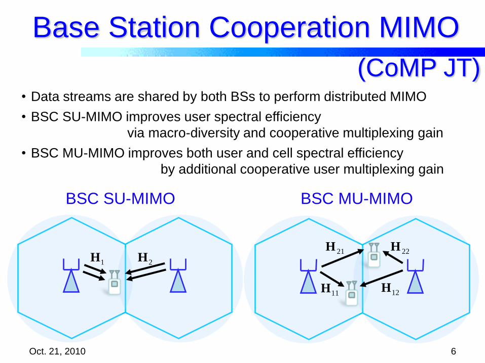
Base Station Cooperation MIMO
Oct. 21, 2010 6
11H
21H 22H
12H
BSC MU-MIMO
1H 2H
BSC SU-MIMO
(CoMP JT)• Data streams are shared by both BSs to perform distributed MIMO
• BSC SU-MIMO improves user spectral efficiency
via macro-diversity and cooperative multiplexing gain
• BSC MU-MIMO improves both user and cell spectral efficiency
by additional cooperative user multiplexing gain

Open Problem in BSC
• ClusteringCooperative BS set selection to
perform effective BSC MIMO
(static clustering or dynamic clustering)
• Backhaul architectureSmart backhaul architecture to share data streams with low latency
by using X2 interface and/or Remote Radio Head (RRH)
• Cell planning schemeInnovation from non-overlapped to overlapped cell planning by
controlling Inter Site Distance (ISD) or BS antenna down tilting
• Feedback schemeCodebook based digital precoding is not enough for BSC MU-MIMO
and additional feedback is needed (digital or analog)
Oct. 21, 2010 7
ISD
BSC cluster

Cooperation Region
Oct. 21, 2010 8
• Cell-inner (non-cooperative region)
• BSC MIMO is not effective due to unbalanced pathloss (high SIR)
• Single-cell MIMO is efficient at cell-inner
• Cell-edge (cooperative region)
• BSC MIMO is effective at cell-edge due to balanced pathloss (low SIR)

100 200 300 400 500 600 7000
2
4
6
8
10
12
14
Distance from BS to user [m]
Use
r sp
ectr
al
eff
icie
ncy
[b
ps/
Hz]
SC-SU transmission
BSC-MU transmission
Fractional CoMP
Oct. 21, 2010 9
Turning point
Cooperation regionNon-cooperation
region
• Non-cooperation region
– Single Cell Single User (SC-SU) MIMO transmission from local BS
is efficient
: Local BS : Neighbor BS
: Strong signal
: Weak interference

100 200 300 400 500 600 7000
2
4
6
8
10
12
14
Distance from BS to user [m]
Use
r sp
ectr
al
eff
icie
ncy
[b
ps/
Hz]
SC-SU transmission
BSC-MU transmission
Fractional CoMP
Oct. 21, 2010 10
Turing point
Cooperation regionNon-cooperation
region
• Cooperation region
– BSC Multi-User (BSC-MU) MIMO by local and cooperative BSs
is effective
: Local BS : Cooperative BS
: Non-cooperative BS
: Strong signal : Weak
interference
Fractional CoMP
11
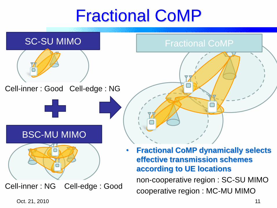
SC-SU MIMO Fractional CoMP
Cell-inner : Good Cell-edge : NG
Cell-inner : NG Cell-edge : Good
BSC-MU MIMO
Oct. 21, 2010
• Fractional CoMP dynamically selects
effective transmission schemes
according to UE locations
non-cooperative region : SC-SU MIMO
cooperative region : MC-MU MIMO
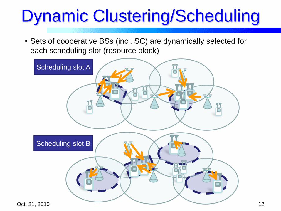
Dynamic Clustering/Scheduling
Oct. 21, 2010 12
Scheduling slot A
Scheduling slot B
• Sets of cooperative BSs (incl. SC) are dynamically selected for
each scheduling slot (resource block)

Distributed Clustering
User selection
Decision on
CoMP
Cooperation
user selection
Cooperation
request
Judgment of
CoMP
Response OK
Data sharing
CoMP starts
Master cell Cooperation cell
: Master cell : Cooperation cell
Oct. 21, 2010 13
• Dynamic clustering algorithm by using distributed cooperative controller

Distributed Clustering
User selection
Decision on
CoMP
Cooperation
user selection
Cooperation
request
Judgment of
CoMP
Response OK
Data sharing
CoMP starts
Master cell
: Master cell
Oct. 21, 2010 14
• Dynamic clustering algorithm by using distributed cooperative controller
Cooperation cell
: Cooperation cell

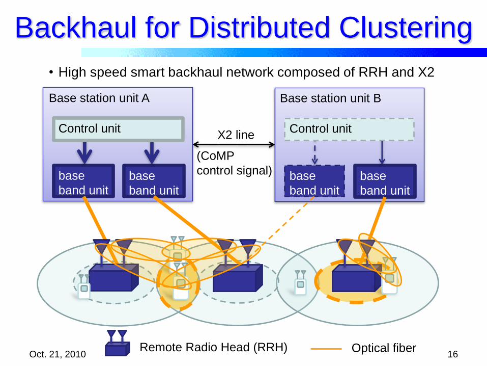
Backhaul for Distributed Clustering
Oct. 21, 2010 15
Base station unit A Base station unit B
base
band unit
base
band unit
base
band unit
base
band unit
Control unit Control unitX2 line
Optical fiberRemote Radio Head (RRH)
• High speed smart backhaul network composed of RRH and X2
(CoMP
control signal)
Backhaul for Distributed Clustering
Oct. 21, 2010 16
Base station unit A Base station unit B
base
band unit
base
band unit
base
band unit
base
band unit
Control unit Control unitX2 line
Optical fiberRemote Radio Head (RRH)
(CoMP
control signal)
• High speed smart backhaul network composed of RRH and X2
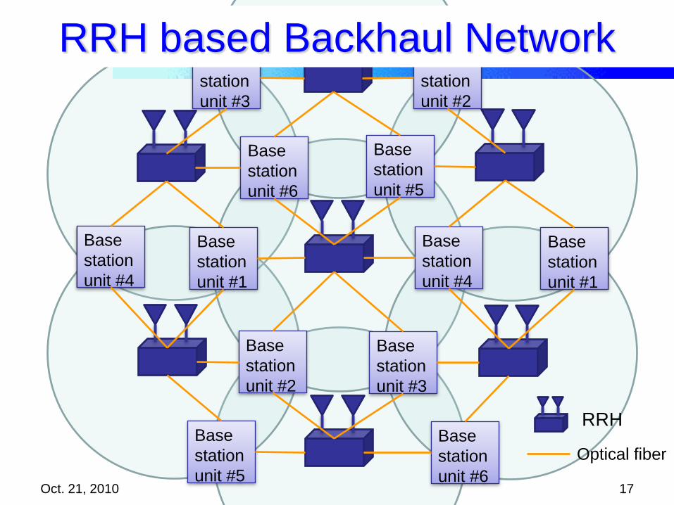
Oct. 21, 2010 17
Optical fiber
Base
station
unit #1
Base
station
unit #2
Base
station
unit #3
Base
station
unit #4
Base
station
unit #5
Base
station
unit #6
Base
station
unit #4
Base
station
unit #1
Base
station
unit #5
Base
station
unit #6
Base
station
unit #3
Base
station
unit #2
RRH based Backhaul Network
RRH
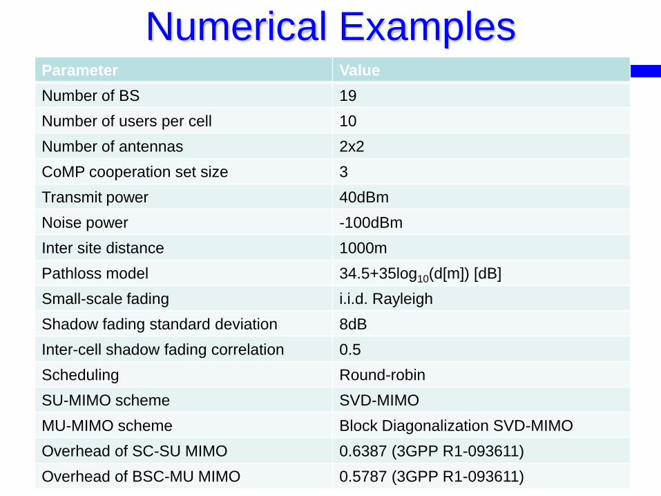
Numerical Examples
Oct. 21, 2010 18
Parameter Value
Number of BS 19
Number of users per cell 10
Number of antennas 2x2
CoMP cooperation set size 3
Transmit power 40dBm
Noise power -100dBm
Inter site distance 1000m
Pathloss model 34.5+35log10(d[m]) [dB]
Small-scale fading i.i.d. Rayleigh
Shadow fading standard deviation 8dB
Inter-cell shadow fading correlation 0.5
Scheduling Round-robin
SU-MIMO scheme SVD-MIMO
MU-MIMO scheme Block Diagonalization SVD-MIMO
Overhead of SC-SU MIMO 0.6387 (3GPP R1-093611)
Overhead of BSC-MU MIMO 0.5787 (3GPP R1-093611)
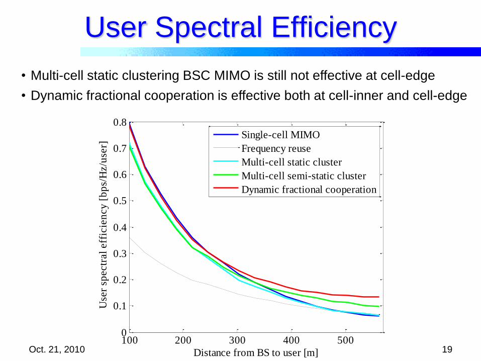
User Spectral Efficiency
Oct. 21, 2010 19
• Multi-cell static clustering BSC MIMO is still not effective at cell-edge
• Dynamic fractional cooperation is effective both at cell-inner and cell-edge
100 200 300 400 5000
0.1
0.2
0.3
0.4
0.5
0.6
0.7
0.8
Distance from BS to user [m]
Use
r sp
ectr
al
eff
icie
ncy
[b
ps/
Hz/u
ser]
Single-cell MIMO
Frequency reuse
Multi-cell static cluster
Multi-cell semi-static cluster
Dynamic fractional cooperation

CDF of User Spectral Efficiency
Oct. 21, 2010 20
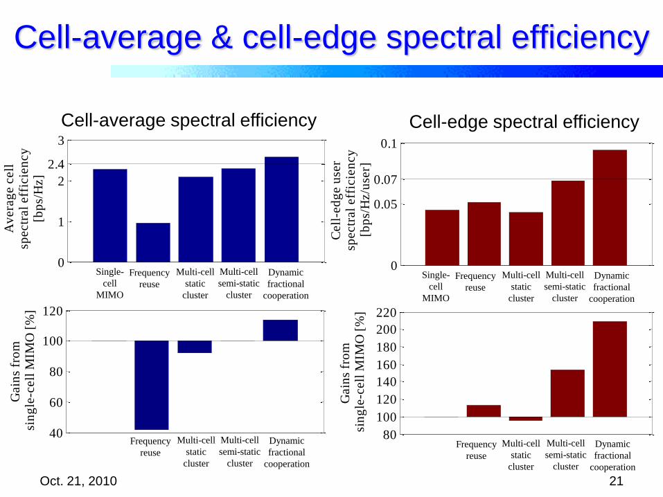
• Both cell-average and 5% cell-edge user spectral efficiency are improved
0 0.1 0.2 0.3 0.4 0.50
0.2
0.4
0.6
0.8
1
0.05
User spectral efficiency [bps/Hz/user]
CD
F
Single-cell MIMO
Frequency reuse
Multi-cell static cluster
Multi-cell semi-static cluster
Dynamic fractional cooperation
40
60
80
100
120
Gain
s fr
om
sin
gle
-cell
MIM
O [
%]
0
1
2
3
2.4
Av
era
ge c
ell
spectr
al
eff
icie
ncy
[bp
s/H
z]
0
0.05
0.1
0.07
Cell
-ed
ge u
ser
spectr
al
eff
icie
ncy
[bp
s/H
z/u
ser]
80
100
120
140
160
180
200
220
Gain
s fr
om
sin
gle
-cell
MIM
O [
%]
Cell-average & cell-edge spectral efficiency
Oct. 21, 2010 21
Single-
cell
MIMO
Multi-cell
static
cluster
Dynamic
fractional
cooperation
Cell-average spectral efficiency Cell-edge spectral efficiency
Frequency
reuse
Multi-cell
semi-static
cluster
Multi-cell
static
cluster
Dynamic
fractional
cooperation
Frequency
reuse
Multi-cell
semi-static
cluster
Single-
cell
MIMO
Multi-cell
static
cluster
Dynamic
fractional
cooperation
Frequency
reuse
Multi-cell
semi-static
cluster
Multi-cell
static
cluster
Dynamic
fractional
cooperation
Frequency
reuse
Multi-cell
semi-static
cluster

Cell Planning for BSC
Oct. 21, 2010 22
Form Cluster?
Cooperative BS
Uncooperative BS
Desired Signal
Interfering Signal
Desired for JT CoMP or
Interfering for CS/CB
Non-BSC Cell Planning BSC Cell Planning
Typical Cell Planning Design
• Inter-site distance? BS Locations?
• Tx powers? Antenna parameters?
BSC Cell Planning Design
• Typical Cell Planning Design
+• Cell Partitioning? (Cooperation regions)
• BSC Cluster Partitioning?
Other Cells
are treated as
interferers so
coverage
overlap is
avoided
Cooperate
here?
*optimum ISD estimate results in
optimum network cost estimate
ISD?Intersite distance (ISD)

Dynamic Fractional CoMP
BSC Cluster TypesHigh-speed
backboneInter site CoMP
intracluster
cell-edge
(yellow)cell-inner
(grey)
intercluster
cell-edge
(blue)
site-edge
(light blue)
Intra site CoMP
Antennas of one transmission point of the same CoMP
cooperating set. Antenna directivity () is indicated by
the curves .
intracluster
cell-edge
(yellow)cell-inner
(grey) site-edge
(light blue)
High-speed
backboneHybrid site CoMP
Oct. 21, 2010 23
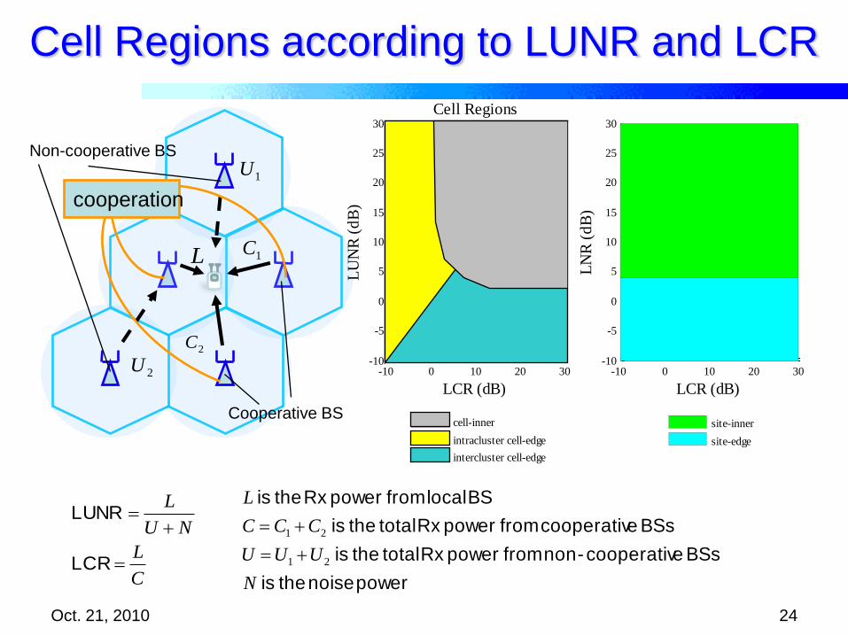
Cell Regions according to LUNR and LCR
Oct. 21, 2010 24
L 1C
2C
1U
2U
cooperation
Cooperative BS
Non-cooperative BS
power noise the is
BSs ecooperativ-non from powerRx total the is
BSs ecooperativ from powerRx total the is
BS local from powerRx the is
N
UUU
CCC
L
21
21
C
L
NU
L
LCR
LUNR
-10 0 10 20 30-10
-5
0
5
10
15
20
25
30
LCR (dB)
LN
R (
dB
)
site-inner
site-edge
-10 0 10 20 30-10
-5
0
5
10
15
20
25
30
LCR (dB)
LU
NR
(d
B)
Cell Regions
cell-inner
intracluster cell-edge
intercluster cell-edge

Cooperation Region according to LUNR and LCR
L 1C
1U
Non-cooperative SVD
(NC-SVD)
L 1C
1U
BSC Block Diagonalization
SVD (BD-SVD)
Cooperation
Region
Non-
cooperation
Region
Oct. 21, 2010 25

Cooperation Regions of BSC Clusters
Smallest
cooperation
region area
Oct. 21, 2010 26
Non-cooperation
region
Cooperation
region

Cooperative Region and Cluster Cells of
Dynamic Fractional CoMP
1
2
5
6
7
9
10
11
12
13
14
15
16
17
18
19
20
21
25
26
27
28
29
30
31
32
33
34
37
38
39
40
43
44
45
46
47
48
49
50
51
55
56
57
58
59
60
61
62
63
64
65
66
67
68
69
70
71
72
73
74
75
76
77
78
79
80
81
Grid Location (m)
Gri
d L
ocati
on
(m
)
48
3
-400 -200 0 200 400 600
-400
-200
0
200
400
600 Non-cooperation
Region (cyan)
Cooperation
Region (pink)
Boundary of Cluster Cell (3,4,8)
Boundary of
Cluster Cell (3,8,19)
Boundary of
Cluster Cell (2,3,19)
Boundaries of Cluster Cell
(1,2,3)
Boundary of
Cluster Cell (1,3,8)
cluster cell is the area at which its associated BSC Cluster performs CoMP to the UEs inside the area
Largest
cooperation
region area
Oct. 21, 2010 27

ISD Dependency
Oct. 21, 2010 28
Saturation due to
intercluster
interferenceFloor due to noise
• Inter site distance can be optimized via coverage of cooperation region
Dynamic fractional
Inter site dynamic
Inter site static
Hybrid static
Intra site static

Cell Planning for CoMP Conclusion
• Our Contribution: A framework
for cell planning of CoMP
networks based on receive
signal strength ratios
– Cluster Types
– LUNR and LCR
– Cell regions
– Cooperation regions
– Cluster cells
– Spectral Efficiency of CoMP
– ISD Dependency
– Cluster Selection Optimization
Form Cluster?
Cooperative BS
Uncooperative BS
BSC Cell Planning
BSC Cell Planning Design
• Typical Cell Planning Design
+• Cell Partitioning? (Cooperation regions)
• BS Cluster Partitioning?
Cooperate
here?
ISD?
I. Garcia, N. Kusashima, K. Sakaguchi, K. Araki, S.
Kaneko, Y. Kishi, “Impact of Base Station
Cooperation on Cell Planning,” EURASIP J.
Wireless Commun. and Networking,
Vol. 2010, Article ID 406749, Aug. 2010.
Oct. 21, 2010 29
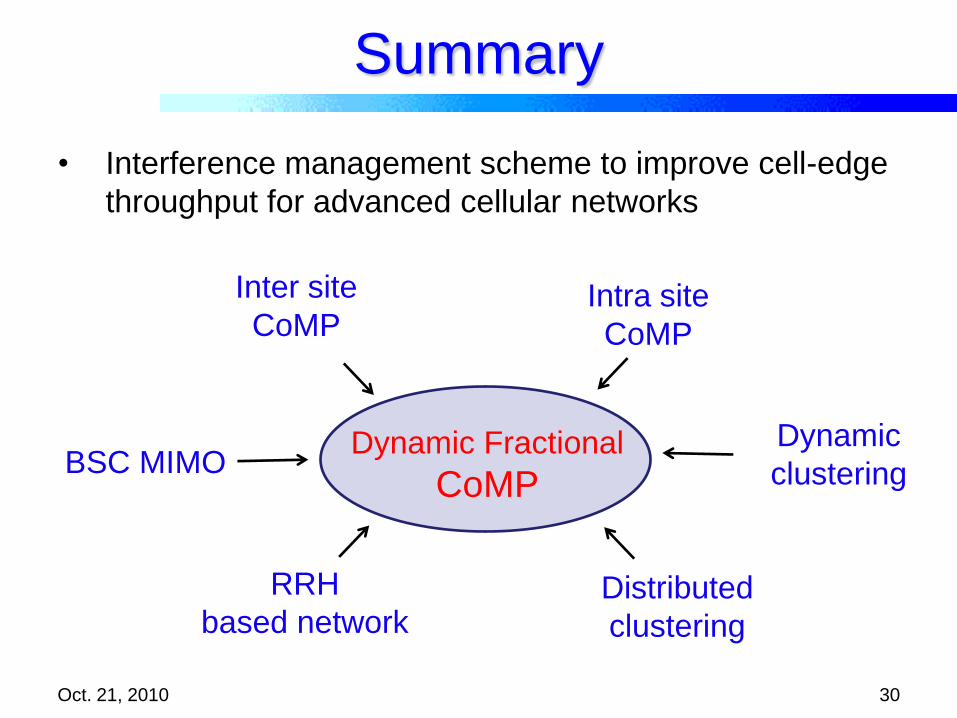
Summary
Oct. 21, 2010 30
• Interference management scheme to improve cell-edge
throughput for advanced cellular networks
Dynamic Fractional
CoMPBSC MIMO
Inter site
CoMPIntra site
CoMP
Dynamic
clustering
Distributed
clustering
RRH
based network

Future Perspective
Oct. 21, 2010 31
• CoMP MIMO transmission scheme using non-linear algorithm
such as dirty paper coding or convex optimization
• CoMP between BSs with different cell size and backhaul
architecture (heterogeneous network)
• Standardization of Dynamic Fractional CoMP for
LTE-Advanced (Release 11) and amendment of 16m

Co-scheduling
• Average receive SNR
of 1st user
Oct. 21, 2010 32
d1 [m]
d2 [
m]
0 100 200 300 400 500 600 7000
100
200
300
400
500
600
700
-5
-4
-3
-2
-1
0
2
2221
211222111
P
gg
gggg
The n
orm
aliz
ed S
NR
of
1stuser
Co-schedulingThe BSs select users with the same SINR
• d1 = d2
• SNR is maximized
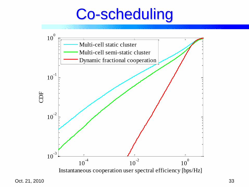
Co-scheduling
Oct. 21, 2010 33
10-4
10-2
100
10-3
10-2
10-1
100
Instantaneous cooperation user spectral efficiency [bps/Hz]
CD
F
Multi-cell static cluster
Multi-cell semi-static cluster
Dynamic fractional cooperation
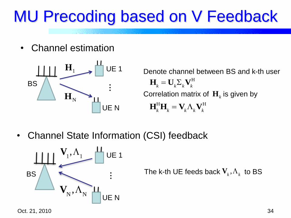
MU Precoding based on V Feedback
Oct. 21, 2010 34
UE N
UE 1
V
N,
N
…
V
1,
1
• Channel State Information (CSI) feedback
The k-th UE feeds back to BS V
k,
kBS
BS
UE N
UE 11H
NH
…
• Channel estimation
H
k U
k
kV
k
H
Denote channel between BS and k-th user
H
k
HH
k V
k
kV
k
H
Correlation matrix of is given bykH

MU Precoding based on V Feedback
Oct. 21, 2010 35
• Precoding calculation
The k-th user’s precoding matrix is obtained by
\k k k
W V V
%Hk
H %Hk V
\k
H
Hk
HH
kV
\k
V\k
V
k
k
HU
k
HU
k
kV
k
HV
\k
V\k
H
Vk
kV
k
HV
\k
H
kkk
H
kk
H
kk
H
kkk
H
k
H
kkk
H
k
VΛV
VΣΣV
VΣUUΣVHH
~~~
~~~~
~~~~~~~~
Correlation matrix of block diagonalized channel matrix is represented askH
This equation can be expressed in another way using ED of as
Denote (Block diagonalized channel)
%H
k H
kV
\k
%Uk%
k%V
k
H
kH
V\k
H V1
L Vk1
Vk1
L VK
V\k
HV
\k
O
H
k kH HIt can be calculated by using reconstructed
Finally can be obtained
H
k kH H
H
kV
k,V
k
\k
V
is given by k-th user’s feedback
can be calculated by other user’s feedback
Finally can be reconstructedH
k kH H
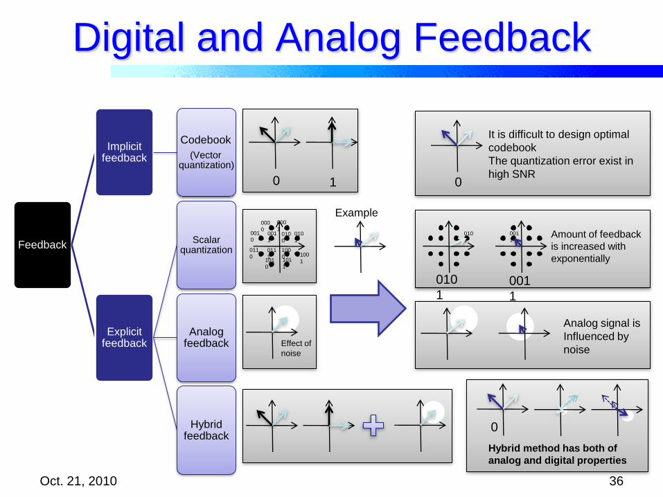
Digital and Analog Feedback
Oct. 21, 2010 36
0 1
000
1000
0001
0001
1010
0
010
1
011
0
011
1
100
0 100
1101
0
101
1
Effect of
noise
0
010
1
001
1
010
1001
1
Example
0
It is difficult to design optimal
codebook
The quantization error exist in
high SNR
Amount of feedback
is increased with
exponentially
Analog signal is
Influenced by
noise
Hybrid method has both of
analog and digital properties
Feedback
Implicit feedback
Codebook
(Vector quantization)
Explicit feedback
Scalar quantization
Analog feedback
Hybrid feedback
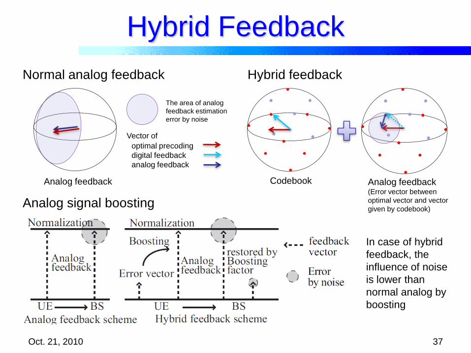
Hybrid Feedback
37
optimal precoding
digital feedback
analog feedback
The area of analog
feedback estimation
error by noise
Codebook Analog feedback(Error vector between
optimal vector and vector
given by codebook)
Analog feedback
Normal analog feedback Hybrid feedback
Analog signal boosting
Vector of
In case of hybrid
feedback, the
influence of noise
is lower than
normal analog by
boosting
Oct. 21, 2010

Numerical Examples
Oct. 21, 2010 38
parameter Value
Channel model AWGN
Channel
estimation errorLTE
Codebook LTE Rel.8
DL/UL SNR Same
MIMO system 4X1 SU-MISO
Feedback
method
Digital
Feedback(fixed)
Additional
feedback
Codebook 4 bits Nothing
Analog 4 bits 4 symbols
Hybrid 4 bits 4 symbols
H H
1 2 1 1 2 2F
1,
2d V V V V V V
Chordal distance
Metric of distance between two matrices
The hybrid feedback method gives
accurate channel state information
Numerical Examples
Oct. 21, 2010 39
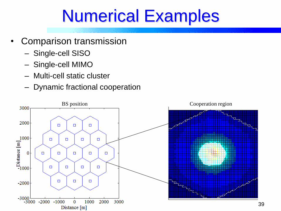
• Comparison transmission
– Single-cell SISO
– Single-cell MIMO
– Multi-cell static cluster
– Dynamic fractional cooperation
BS position Cooperation region


![Fractional Cascading Fractional Cascading I: A Data Structuring Technique Fractional Cascading II: Applications [Chazaelle & Guibas 1986] Dynamic Fractional.](https://static.documents.pub/doc/80x56/56649ea25503460f94ba64dd/fractional-cascading-fractional-cascading-i-a-data-structuring-technique-fractional.jpg)


