

N 7 3 33831
DYNAMICS AND CONTROL OF DETUMBLING A DISABLED
SPACECRAFT DURING RESCUE OPERATIONS
(Summary Final Report on NASA Grant NCR 39-009-̂ 210)
by
Marshall H. Kaplan
Associate Professor of Aerospace Engineering
Astronautics Research Report
No. 73-10
Department of Aerospace Engineering
The Pennsylvania State University
University Park, Pennsylvania
September 1973
https://ntrs.nasa.gov/search.jsp?R=19730025098 2020-03-14T23:43:49+00:00Z
ABSTRACT
i
Results of a two-year research effort at The Pennsylvania
State University (NASA NCR 39-009-210) on dynamics and control of
detumbling a disabled spacecraft during rescue operations are
summarized. Answers to several basic questions about associated
techniques and hardware requirements were obtained. Specifically,
efforts have included development of operational procedures, conceptual
design of remotely controlled modules, feasibility of internal
moving mass for stabilization, and optimal techniques for minimum-
time detumbling. Results have been documented in several reports
and publications.
ii
TABLE OF CONTENTS
page
ABSTRACT ii
1. INTRODUCTION . 1
2. SUMMARY OF TECHNICAL ACHIEVEMENTS 2
2.1 The Nature of Tumbling 32.2 Examples of Tumbling Situations 62.3 Operational Considerations 92.4 Automated External Detumbling Module 122.5 Optimal Detumbling with Thrusters 162.6 Automated Internal Stabilizing Devices 17
3. PUBLICATIONS AND REPORTS RESULTING FROM THIS STUDY . . 24
4. CONCLUSIONS AND RECOMMENDATIONS 25
iii

1. INTRODUCTION
NASA Grant NCR 39-009-210 was awarded on June 1, 1971 for the
purpose of studying dynamics and control aspects of detumbling a
disabled spacecraft during rescue operations. The grant expired
on July 31, 1973. Answers to several basic questions related to
external and internal detumbling were obtained. Specific problem
areas were identified, and mission requirements and constraints were
formulated for the purpose of developing operational sequences and
conceptual hardware designs. Work has been well documented, and
associated publications are listed in Section 3. For detailed technical
discussions refer to these documents.
The primary objective of the study was to develop technology
related to detumbling a large passive spacecraft for the purpose of
rescuing the crew. Efforts have included development of operational
procedures, conceptual design of remotely controlled modules,
feasibility of internal moving mass for stabilization, and optimal
techniques for minimum-time detumbling. Although emphasis has changed
since the original statement of work was written, the most critical
and timely aspects have been considered.
A preliminary design of an unmanned module for automatic dock
and detumble (MADD) has been carried out. Extensive analyses on
dynamics and controls problems has been completed. These include
synthesis of a continuously throttable position control system and
an initial design of an attitude control system. A movable mass
control system to convert tumbling motion of a spacecraft into simple
spin has been devised. The equations of motion of a rigid spacecraft

with attached control mass have been formulated. Such a control
system may increase or decrease the system energy to its maximum
or minimum state. In the latter case stability and a low spin rate
result. A control law relating mass motions to vehicle motions was
selected based on Lyapunov stability theory. For a selected space-
craft and realistic initial conditions, it was shown that a movable
mass device is capable of decreasing the kinetic energy of the system
and establishing a simple spin state about the axis of maximum inertia
within a short time interval, thus, demonstrating feasibility of the
concept. In addition, optimization techniques have been employed to
generate displacement profiles for the general problem of a tumbling
asymmetrical body.
Several graduate students have participated in this work. To
date, one master of science thesis and one Ph.D. dissertation have
been written on the study problems and solutions. One other thesis
in this area is still being completed.
2. SUMMARY OF TECHNICAL ACHIEVEMENTS
In the operation of future manned space vehicles there is always
a finite probability that an accident will occur which results in
uncontrolled tumbling of a spacecraft. The process of detumbling such
a vehicle may represent a major part of the rescue operation if crewmen
cannot evacuate while tumbling. Hard docking by a manned rescue
craft is not possible because of complex maneuvers which would
probably require excessive accelerations and fuel usage. In addition,
the rescue crew would be exposed to an extremely hazardous environment
since the tumbling vehicle may be larger than the rescue craft.

Therefore, elimination of tumbling motion presents a very difficult
problem which must be resolved to fulfill a complete space rescue
capability.
The most general type of passive attitude motion is referred to
as "tumbling". All three orthogonal components of angular velocity
may be large, and ther.e is no preferred axis of rotation. Since no
spacecraft is absolutely rigid, tumbling motion will tend toward
steady spin due to energy dissipation. However, large bodies such as
manned space bases have relatively low dissipation rates and may
require many days or weeks to passively stabilize at a constant spin
rate about a single axis. If this state were reached, despinning is
somewhat easier than detumbling. Two philosophies were employed to
consider promising methods of implementing attitude control; torque
application from outside and built-in autonomous devices. The first
category includes the use of fluid jets from.a shuttle orbiter and
a small automated thruster package to track and dock with the tumbling
craft. Internal devices include self-contained, acceleration-
activated mechanisms which may vary the moments of inertia or apply
thrust with time in order to stabilize motion to steady spin or
eliminate all angular momentum.
2.1 The Nature of Tumbling
Angular momentum states have been classified according to motion
and missions in which such states are likely to occur. Simple spin
is angular motion about a single body axis and is usually associated
with passive attitude stabilization and the steady state of initially
perturbed or tumbling bodies. Tumbling occurs immediately after a
significant attitude perturbation, but eventually decays into simple

spin. The nature of general torque-free tumbling motion of rigid
bodies has been well established and may be described analytically»
or geometrically. For an unsymmetrical body the equations of motion
are non-linear and cannot be solved without difficulty. A geometrical
interpretation has been formulated by Poinsot. The "Poinsot ellipsoid"
illustrated in Figure 1 represents the locus of all possible values
of angular velocity of the body which satisfy the constant kinetic
energy condition. This imaginary ellipsoid is fixed to the body and
moves with it, as shown. Attitude motion can then be described as
the Poinsot ellipsoid rolling without slip on an inertially fixed
plane with its center at a fixed distance from this plane. If the body
is symmetric, the geometric interpretation is simpler and is illustrated
in Figure 2. A "body cone" whose apex is at the center of mass and
is fixed to the body rolls on an inertially fixed "space cone" whose
axis coincides with .the angular momentum vector. The common cone
element coincides with the angular velocity vector.
Tumbling is the immediate result of a significant attitude per-
turbation to an uncontrolled vehicle with little or no initial spin.
This situation is coupled with continuous angular motion of all three
principal body axes, i.e., no inertially oriented axis exists. Crew-
men trapped inside such a vehicle could not easily escape and may not
even be able to move about due to the changing nature and magnitudes
of accelerations. This kind of attitude motion makes rescue very
difficult. In general, elimination of angular motion of a large body
is a complicated process, because it must be done either from a non-
tumbling frame outside the body or by a possibly massive internal
device which may only stabilize the motion to steady spin. (Publication 3)

-5-
INERTIA ELLIPSOID
INVARIABLE
PLANE
BODYFIXED
AXES
POLHODE
HERPOLHODE
Figure 1. Geometric Interpretation of General Attitude Motion
BODY CONE
BODY FIXED AXES
SPACE CONE
Figure 2. Geometric Interpretation of Axial Body Motion

2.2 Examples of Tumbling Situations
In order to determine the requirements for a device or concept
to detumble a large spacecraft some assumptions must be adopted about
the causes of tumbling and calculations made to determine resulting
maximum rates of tumble. An analysis of realistically determined
situations was made with selected spacecraft which are thought to
represent future mission hardware. Primary expected causes of
tumbling associated with loss of control are vehicle-vehicle collisions,
escaping atmosphere, pressure vessel rupture, runaway attitude thruster,
and hard-over gimbal during a main engine firing.
Four configurations were selected based on a recent North
American Rockwell study. These are the modular space station, small
space vehicle, Mark II orbiter, and generation 1 orbiter. Configurations
are shown in Figure 3. Mass and moments of inertia were calculated for
each vehicle and are listed in Table 1. Collisions between all
combinations of these vehicles were considered, except Mark II-
generation 1 orbiter encounters. Such mishaps were assumed to occur
during docking operations with a relative velocity of 1.5 m/sec with
misalignment of 4 deg in angle and 0.61 m in displacement in addition
to an angular vehicle rotation rate of 0.1 deg/sec. Impact parameter
values were assumed and energy methods of analysis were used to
determine resulting tumbling rates. The escaping atmosphere situation
was assumed for the modular space station and small space vehicle.
Pressure wall perforation could result from meteorite penetration,
internal explosion, etc. The effect on attitude is similar to that
of a reaction jet as the inside atmosphere escapes into space. Worst
cases were assumed with respect to puncture location and thrust produced.

TANKS
4.6m
TYPICAL QUADEXHAUSTD I R E C T I O N S
* 11 m
— I
DOCKINGPORT
Modular Space Station Small Space Vehicle
53 m
/734 m
Mark II Orbiter Generation 1 Orbiter
Figure 3. Configurations Considered in Tumbling Analysis

Escape of fluids from tanks into space will have similar results to
those of an escaping atmosphere. A single tank was assumed ruptured
for each configuration studied. Worst case conditions prevailed, e.g.,
contents escaped in one direction producing thrust with a large moment
arm about the center of mass. Since only the two orbiter configurations
have steerable main rockets, the hard over gimbal situation applied to
them exclusively. Two thrusters on each vehicle were assumed fixed at
maximum gimbal angle and fired for 15 sec. The final tumble-producing
situation is concerned with a malfunctioning attitude thruster which is
assumed to thrust for one minute. (Publication 1)
Table 1 Mass Properties of Configurations Considered
Mass (Kg)
Moments of Jnertia Ixx
*YY
Izz
Products of Inertia I „(kg-m )
^"V7A£
^"V7
ModularSpace
Station
100,000
0.636xl07
0. 664x10 7
0.515xl07
0.19xl06
0.785xl04
0.176xl04
SmallSpace
Vehicle
11,400
0.298xl05
1.34xl05
1.34xl05
0
0
0
Mark IIOrbiter
138,000
3.4xl06
24.8xl06
28.3xl06
-1.22xlOA
3.59xl05
0.271xl04
Generation 1Orbiter
81,000
0.993xl06
8.14xl06
8.50xl06
0
0
0

Results of worst case situations are summarized in Table 2. It
must be stressed that the values of angular rates appearing in this
Table represent only the initial motion at the end of application of
perturbing torque. Since the X, Y, and Z axes do not generally coin-
cide with the principal body axes (motion about the maximum and mini-
mum principal axes is stable for a rigid body) these spin modes will
become tumbling modes within a few revolutions of the vehicle. Some
of the results are given as ranges of angular rates because of parame-
ter uncertainties in the analysis. In general, one could conclude
that angular rates could be expected up to about 9.0 RPM for the large
vehicles and up to about 14.7 RPM for the small space vehicle. The
escaping atmosphere situation for this last vehicle is considered a
catastrophic one, because a spin rate of 52 RPM would probably result
in massive structural failure. Therefore, rescue from this spacecraft
"would be~neither possible nor necessary. A few cases could not be
analyzed due to a lack of data on configuration dimensions and layout
details. However, all cases in which rescue is possible appear to be
limited to initial angular rates of less than 10 RPM or 60 deg/sec for
large vehicles and less than 15 RPM or 90 deg/sec for the small
vehicle.
2.3 Operational Considerations
In general orbital rescue missions may be divided into three phases:
rescue alert and rendezvous with the disabled vehicle, rescue operations
proper, and return of the rescue vehicle. The second phase is of primary
concern here, since a major part of this phase involves detumbling a
large, manned vehicle before evacuation and repairs can take place.

10
O H•H <1)•U 4-1tfl -HH ,00) MG O
M0)•urt
00c
H
i-(OJ
M 0)4J
J<5 T-l
S-fia o
•9H
u<d <uCXrHM O
•Ht-l X!t-l 0)
CO
a)oCOP. C
CO O
to corH 4J3 co
T3oa
Q
m•
oII
P.O.
co<uoQ
a&o
I«0
N
SJ
3O
I<•
4JO
S3co<UOQ
coOco
%oo <ae xiH O.(X COCO Oo 0CO WM <
00C
•H CO(XTJtO -HO 3CO rHM Pf
M
$a rH
tO -Hac o
ooc•Hco
O (UC w3 M
11
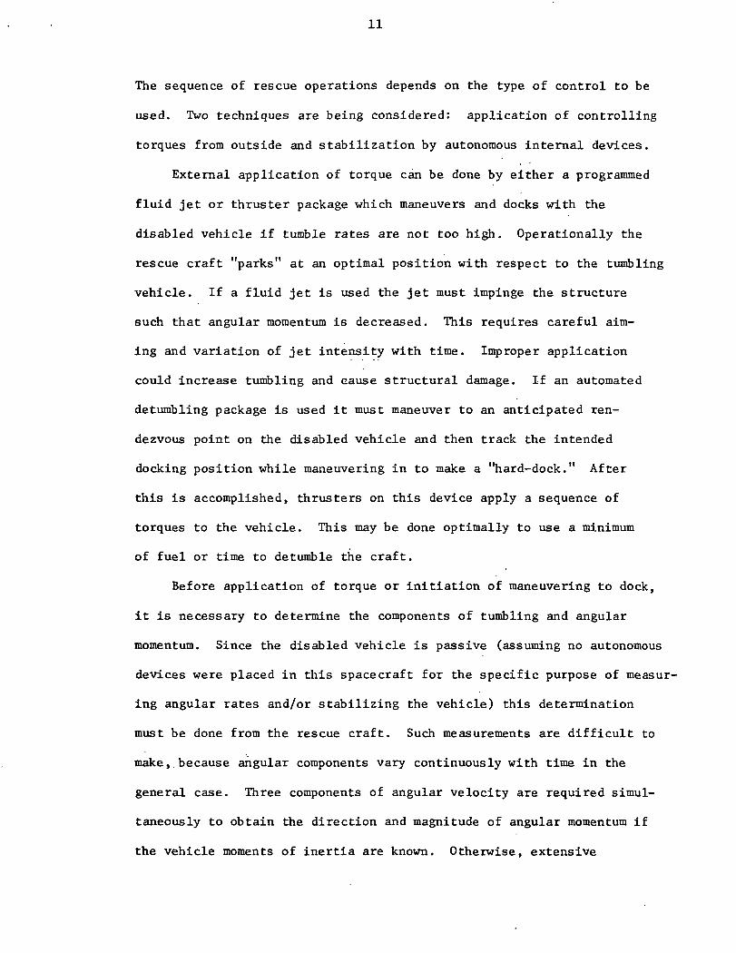
The sequence of rescue operations depends on the type of control to be
used. Two techniques are being considered: application of controlling
torques from outside and stabilization by autonomous internal devices.
External application of torque can be done by either a programmed
fluid jet or thruster package which maneuvers and docks with the
disabled vehicle if tumble rates are not too high. Operationally the
rescue craft "parks" at an optimal position with respect to the tumbling
vehicle. If a fluid jet is used the jet must impinge the structure
such that angular momentum is decreased. This requires careful aim-
ing and variation of jet intensity with time. Improper application
could increase tumbling and cause structural damage. If an automated
detumbling package is used it must maneuver to an anticipated ren-
dezvous point on the disabled vehicle and then track the intended
docking position while maneuvering in to make a "hard-dock." After
this is accomplished, thrusters on this device apply a sequence of
torques to the vehicle. This may be done optimally to use a minimum
of fuel or time to detumble the craft.
Before application of torque or initiation of maneuvering to dock,
it is necessary to determine the components of tumbling and angular
momentum. Since the disabled vehicle is passive (assuming no autonomous
devices were placed in this spacecraft for the specific purpose of measur-
ing angular rates and/or stabilizing the vehicle) this determination
must be done from the rescue craft. Such measurements are difficult to
make, because angular components vary continuously with time in the
general case. Three components of angular velocity are required simul-
taneously to obtain the direction and magnitude of angular momentum if
the vehicle moments of inertia are known. Otherwise, extensive

12
measurements are required. This latter situation is very likely to be
the case if an explosion or loss of propellant has taken place. Tech-
niques which employ visual observations, radar scanning, and laser
reflectors in conjunction with onboard computers are likely candidates
for these measurements. Special passive reflectors may be required on
the disabled vehicle, but these are small, simple devices which can be
mounted before launching all manned vehicles. (Publication 3)
2.4 Automated External Detumbling Module
Since the expected tumbling rates for large vehicles are relatively
low, a small maneuverable thruster package deployed from the rescue
craft could rendezvous and dock with the disabled vehicle while tumbling.
A Module for Automatic Dock and Detumble (MADD) could perform an orbital
transfer from the shuttle in order to track and dock at a preselected
point on the distressed craft. Once docked MADD could apply torques by
firing its thrusters to detumble the passive vehicle. This could be
done in a minimum time or fuel sequence.
Design of a MADD type spacecraft is influenced by mission objec-
tives and systems constraints. It must maneuver to, dock with, and
detumble a large vehicle with limited fuel, and it must be adaptable to
varying situations. Size is constrained by cargo bay dimensions of the
rescue craft and to some extent geometry of the disabled vehicle. A
preliminary configuration for MADD is shown in Figure 4. This version
is designed to use an existing docking port on the disabled vehicle,
although, there are some situations in which this is not possible or
desirable. Other types of attachment devices may be adapted for those
cases. All subsystems are contained within the octagonal structure and

-13-
C O M P A T A B L E
D O C K I N G
S Y S T E M
Figure 4. Details of MADD Configuration

14
include control electronics, attitude control gyros, command and tele-
metry, propulsion, power, and various sensors.
The control system has three basic operating modes: transfer,
dock, and detumble. During transfer from the rescue craft this system
maintains attitude and reorients MADD just before entering the docking
mode in which tumble tracking and attachment take place. As soon as
hard docking is accomplished the detumble mode is initiated. During
this last phase gyro controllers are locked and rate gyros are used for
attitude reference. A single propulsion system will satisfy the require-
ments for transfer, detumble, and momentum dumping. Thrust profiles
during tracking and detumbling phases are computed by an onboard computer
based on measurements from sensors and those taken immediately upon com-
pletion of docking. Optimal sequences are generated in order to detumble
in minimum time with limited thrust when time is a critical factor.
The operational procedure for the use of MADD consists of deploy-
ing the module, transfer to a rendezvous point, tracking a docking port,
hard docking, and detumbling. Before initiating this sequence, the
rescue craft crew must determine the angular momentum and physical state
of the disabled vehicle. An optimum parking position is selected for
the rescue craft based on visual observation advantage, propellant
requirements for maintaining this position, and possible transfer paths
for MADD. Figure 5 shows a situation requiring a minimum propellant
requirement for the rescue craft. Both vehicles share the same orbit
but remain separated along the flight path. Once a stand-off situation
is established, MADD is deployed from the cargo bay and the transfer
phase begins. A general transfer profile .is illustrated in Figure 6.
Direct observation of MADD is possible from the rescue craft during the

-15-
R E S C U EC R A F T
E A R T H
Figure 5. Example of Stand-Off Situation
RENDEZVOUSPOINT
ITRACKING
PHASE
DOCKINGPOINT
TRANSFER PHASE J DISABLEDVEHICLE \
CENTER OF MASS \
Figure 6. Typical Transfer Trajectory for MADD
16
transfer phase. However, during tracking and docking radio and visual
contact may be lost intermittently due to occultation. The rendezvous
point can be selected such that the velocity of MADD at this point will
coincide with the velocity of the disabled vehicle reference point.
This will eliminate the need for a terminal maneuver by MADD before the
tracking phase begins. The rendezvous point should typically be about
3 meters from the docking port. MADD thrusters begin firing to maintain
and then reduce its distance to this port. Passive docking aids may be
required around the port for sensing relative position, orientation,
and velocity. This permits proper alignment during closure and docking.
The process is continued until capture latches are secured. After
detumbling crew evacuation takes place. (Publications 3 and 5)
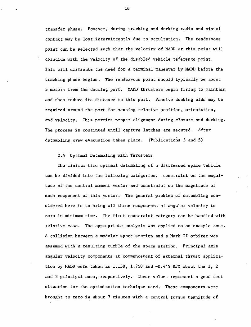
2.5 Optimal Detumbling with Thrusters
The minimum time optimal detumbling of a distressed space vehicle
can be divided into the following categories: constraint on the magni-
tude of the control moment vector and constraint on the magnitude of
each component of this vector. The general problem of detumbling con-
sidered here is to bring all three components of angular velocity to
zero in minimum time. The first constraint category can be handled with
relative ease. The appropriate analysis was applied to an example case.
A collision between a modular space station and a Mark II orbiter was
assumed with a resulting tumble of the space station. Principal axis
angular velocity components at commencement of external thrust applica-
tion by MADD were taken as 1.150, 1.750 and -0.445 RPM about the 1, 2
and 3 principal axes, respectively. These values represent a good test
situation for the optimization technique used. These components were
brought to zero in about 7 minutes with a control torque magnitude of

17
3,390 N-m. Figure 7 shows a time history of the principal axis angular
velocities during application of the optimum control moment. Figure 8
gives a time history of the body fixed thrusts required at point X =
3.9m, Y = 0.89m and Z = 18.3m to give the necessary 3,390 N-m moment
directed opposite to the angular momentum vector. (Publications 2, 3,
and 5)
The second type of constraint presents more difficulty in determin-
ing the optimum minimum time control moment sequence. In this case, the
analysis is not as easily accomplished, and the control moment vector
is not simply directed opposite to the angular momentum vector.
2.6 Automated Internal Stabilizing Devices
A movable-mass control device, which is activated upon initiation
of tumble and is autonomous, can convert tumbling motion into simple spin.
Such a device would greatly facilitate crew evacuation and final despin-
ning by external means. There have been several other suggestions for
using internal devices. Mass expulsion devices require onboard storage
of propellants over long periods. Several thrusters would have to be
dedicated to this type of system. Thus, such schemes could be complex
and massive. Momentum exchange devices could quickly saturate and are
difficult to start in a tumbling situation. Passive energy dissipation
mechanisms are reliable and simple, but they require long periods of
time to reduce kinetic energy if initial rates are low. Of particular
concern here is an internal moving mass system which is programmed to
quickly stabilize motion about the major principal axis.
The complete equations of motion of a rigid spacecraft with attached
control mass have been formulated making no assumptions regarding vehicle
symmetry or magnitude of the transverse angular rates. A control law

2 4
1 - •
o.QC
0
-1 -•
-2 -•
-18-
TIME (SECONDS)
Figure 7. Principal Angular Velocities During Detumbling
200 --
100 -•
0
-100 -
-200
150 -̂SCKL 250
TIME (SECONDS)
350
Figure 8. Body Fixed Thrust Component Profiles During Detumbling

19
relating control mass motions to vehicle motions was selected based on
Liapunov stability theory. A method of determining control system para-
meter values, based on an estimate of the worst case tumble state has
also been developed. For the MSS under previously stated conditions, a
movable mass control system is capable of quickly decreasing the kinetic
energy of the system to its minimum state, establishing a simple spin
about the maximum inertia axis.
It is the function of the control law to relate motion of this mass
to measurable vehicle parameters such that kinetic energy decreases. A
satisfactory control law should not be unnecessarily complicated and
should not have excessive power or sensor requirements. It should how-
ever, require determination of only measurable vehicle parameters, pro-
duce stable responses, and result in a final state of simple spin about
the axis of maximum inertia. For the work considered here, the vehicle
is assumed to have three distinct principal moments of inertia (asym-
metric vehicle). Since initial tumble rates may be large about all three
axes, the equations of motion could not be simplified by linearization.
However, a limited number of simple cases were identified which permitted
development of a suitable control law. Linear mass motion parallel to
the axis of maximum inertia was selected. Simulations indicate that the
MSS can be brought to stable spin with a 1% movable mass in 2 hours using
a displacement amplitude of about 3 meters. Figure 9 illustrates time
histories of angular velocity component magnitudes under the influence
of this control mass. _ _ . .
Observations concerning the use of such a device included:
1. The mass track should be placed as far as possible from the
vehicle center of mass and oriented parallel to the maximum
inertia axis.

-20-
mCo
u03o4Je0)coI-oo
oo
0)rH
60
CD01(Xo
(33S/QVH) A1I0013A

21
2. The control mass size should be as large as possible, while
being consistent with peak force and power limitations.
3. The performance of the control system may be improved through
larger mass amplitudes.
Optimizing the control law can bring further improvement in
stabilization time with the same control mass and initial conditions.
A first-order gradient technique has been used to minimize angular
velocity components along the intermediate and minimum inertia axes.
This open-loop method permits a wide range of initial guesses for mass
position history. Motion of the control mass was assumed to be along a
linear track as discussed above. The control variable is taken as mass
acceleration with respect to body coordinates. Motion was limited to
defined quantities and a penalty function used to insure a given range
of positions. Numerical solutions of the optimization equations verify
that minimum time detumbling is achieved with the largest permissible
movable mass, length of linear track, and positions of the mass on the
two coordinates perpendicular to the linear motion. Also, the mass should
oscillate, about the zero point, on an axis parallel to the major prin-
cipal axis. A minimum mass solution was obtained by fixing the time at
the largest feasible value. The optimal method permits detumbling in
about one-fourth the time when compared to the force control law formula-
tion discussed above. Time histories of angular velocity component
magnitudes for this case are shown in Figure 10. Since stabilization may
require hours, this reduction in time is very significant. In regard
to minimum mass, optimization permits the use of a much smaller mass for
detumbling in the same time. This mass reduction is quite substantial
since very large masses are required. Use of this control system for

-22-
0)03a)
4Jcxo
oU-l
mCo
0)t-i
atoo4JC0)goo
aoiH01
3W)
O
(0ucx,oiH
8!
orH
sMl
'/ I
( 3 3 S / a V « ) A 1 I 0 0 1 3 A

23
actual operations in space is feasible since the velocity and accelera-
tion of the mass, and the power requirement, are low. (Publications 4,
6, 7, and 9)

24
3. PUBLICATIONS AND RESEARCH REPORTS RESULTING FROM THIS RESEARCH
1. , "First Semi-Annual Progress Report on Dynamics and Controlof Escape and Rescue from a Tumbling Spacecraft," NASA Grant NCR39-009-210, December 1971.
2. , "Second Semi-Annual Progress Report on Dynamics and Controlof Escape and Rescue from a Tumbling Spacecraft," NASA Grant NCR39-009-210, June 1972.
3. Kaplan, M. H., "Despinning and Detumbling Satellites in RescueOperations," presented at the 5th Space Rescue Symposium, at the23rd Congress of the International Astronautical Federation,October 1972. Also to appear in Proceedings of the 5th SpaceRescue Symposium. 1973.
4. , "Third Semi-Annual Progress Report on Dynamics and Control ofEscape and Rescue from a Tumbling Spacecraft," NASA Grant NCR39-009-210, December 1972.
5. Snow, W. R., Kunciw, B. G., and Kaplan, M. H., "A Module for Auto-matic Dock and Detumble (MADD) for Orbital Rescue Operations,"Astronautics Research Report No. 73-3, Pennsylvania State University,Dept. of Aerospace Engineering, April 1973.
6. Edwards, T. L., "A Movable Mass Control System to Detumble a Dis-abled Space Vehicle," M.S. Thesis, The Pennsylvania State University,June 1973. Also Astronautics Research Report No. 73-5.
7. Kunciw, B. G., "Optimal Detumbling of a Large Manned SpacecraftUsing an Internal Moving Mass," Ph.D. Thesis, The Pennsylvania StateUniversity, June 1973. Also Astronautics Research Report No. 73-8.
8. Edwards, T. L. and Kaplan, M. H., "Automatic Spacecraft Detumblingby Internal Mass Motion," submitted to the AIAA Journal, 1973.
9. Kaplan, M. H., "Techniques for Detumbling a Disabled Space Base,"to be presented at the 6th Space Rescue and Safety Studies Symposium,Baku, U.S.S.R., October 1973.
10. Kaplan, M. H. and Kunciw, B. G., "Optimal Detumbling of a Large MannedSpacecraft Using an Internal Moving Mass," to be presented at the6th IFAC Symposium on Automatic Control in Space, Tsakhkadzor, Armenia,August 1974.

25
4. CONCLUSIONS AND RECOMMENDATIONS
Results of a two-year study of detumbling techniques related to
orbital rescue missions indicate that several devices may be candidates
for use in future space rescue systems. Both internal and external
devices show promise and may be best applied in combinations. Work
should be continued to completely formulate automatic control logic
associated with tracking and docking of MADD during tumble maneuvers.
Optimum combinations of mass motion and external devices for varying
situations should be sought. Built-in rescue aids should be developed
in conjunction with future space stations. Specific recommendations
with regard to future manned spacecraft designs include:
1) Reflectors designed for tumble state determination should be
placed strategically about the outside of each vehicle.
2) Each new spacecraft design should be examined for possible
inclusion of moving mass and/or passive dissipative devices.
3) Passive sensors for MADD docking alignment should be installed
around all docking ports.
4) Realistic tumble rates are expected to be low, permitting the
use of small thruster modules such as MADD.
5) Internal autonomous devices are desirable but cannot be
expected to completely detumble the vehicle unless they are
massive. Thus, outside torque application should be antici-
pated for future rescue missions.
Future studies should include:
1) Development of MADD units should be considered in depth. New
technology will be required for at least the automatic control
system and sensors.
26
2) Hardware components should be developed for use in determin-
ing tumbling rates through outside observations.
3) An extensive investigation of the properties of fluid jets into
vacuum should be made to determine feasibility and application
with respect to applying detumbling torques.
4) Simple and lightweight mechanisms should be sought for use as
internal controlling elements to aid in detumbling.


