
For internal circulation of BSNL only
E4E4--E5 CIVIL E5 CIVIL
(TECHNICAL)(TECHNICAL)
Structural Design of RCC Bldg Structural Design of RCC Bldg ComponentsComponents(Session (Session –– 2) 2)
WELCOME
• This is a presentation for the E4-E5 Civil Technical
Module for the Topic: Structural Design of RCC Bldg
Components (Session 2)
• Eligibility: Those officers of civil wing who have got the
Up-gradation from E4 to E5.
• This presentation is last updated on 21-4-2011.
• You can also visit the Digital library of BSNL to see this
topic.
For internal circulation of BSNL only
For internal circulation of BSNL only
AGENDA
Design of Various Structural Components
Column Design
Design of Slab
Beam Design
Isolated Footing Design – Imp. Considerations.
Development Length
DESIGN OF RCC STRUCTURE
Design of Various Structural Components –
• After load calculation & analysis for vertical & horizontal
loads, design & of various structural components e.g. –
– Columns,
– Foundations,
– Beams,
– Slabs & staircase etc
are carried out as per various clauses of IS codes with
help from charts & tables given in BIS handbooks.
For internal circulation of BSNL only
Design of Columns
Design of Columns
• After obtaining (i) Vertical load, (ii) Moments due to
horizontal loads on either axis & (iii) Moments due to
vertical loads on either axis, acting on each column, at
all floor levels of the building,
• Columns are designed by charts of SP-16(Design
Aids).
• Design of each column is carried out from the top of
foundation to the roof, varying the amount of steel
reinforcement for suitable groups for ease in design.
Slenderness effects in each storey are also considered
for each column group.
For internal circulation of BSNL only
Design of Columns
Column
A compression member, the effective length > three times
the least lateral dimension.
Short and Slender Compression Members
When both slenderness ratios lex/D and ley/b are <12
• Column is a short column
• If more than 12, then it is long or slender column.
• Slender Columns are designed for Additional Moments
as per Clause 39.7 of IS456
Effective height of column:-
• For effective column height refer table 28 (Annexure E)
of IS:456-2000.
For internal circulation of BSNL only
Design of Columns
Design Of Columns – Important Considerations
(ii) Unsupported Length –
In beam-slab construction, it is the clear distance between the floor &
under side of shallower beam framing into columns in each direction at
next higher floor level.
(iii) Slenderness limits for columns –
The unsupported length between end restraints shall not exceed 60
times the least lateral dimension of a column.
(iv) Minimum Eccentricity – All columns shall be designed for
emin ≥ l/500+ D/30 ≥ 20 mm
Where l= Unsupported length of column in mm. D= Lateral dimension
of column in the direction under consideration in mm.
For internal circulation of BSNL only
Design of Columns
Design Of Columns – Design Approach
• The design of column is complex as it is subjected to axial
loads & moments which may very independently.
Column design requires –
– Determination of the cross sectional dimension.
– The area of longitudinal steel & its distribution.
– Transverse steel.
• The maximum axial load & moments acting along the
length of column are considered for design of the column
section.
• The transverse reinforcement is provided to impart effective
lateral support against buckling to every longitudinal bar.
For internal circulation of BSNL only
Design of Columns
Design Of Columns – Reinforcement Provisions as per
IS:456-
A. Longitudinal reinforcement
• Area of longitudinal reinforcement shall be not less than
0.8% nor more than 6% of cross sectional area of the
column.
• However maximum area of steel should not exceed 4% to
avoid practical difficulties in placing & compacting concrete.
• In pedestals, in which the longitudinal reinf. is not taken into
account in strength calculations, nominal reinforcement
should be not be less than 0.15% of cross sectional area.
• Minimum dia of longitudinal bar should be 12 mm
For internal circulation of BSNL only
Design of Columns
Design Of Columns – Reinforcement Provisions as per
IS:456
A. Longitudinal reinforcement
• Spacing between bars < 300mm along periphery of column
• The minimum number of bars shall be four in rectangular
columns & six in circular columns.
B. Transverse reinforcement (STIRRUPS)
• Diameter of lateral ties should not be less than 1/4th of dia of the
largest longitudinal bar & in no case should be less than 6 mm.
• Spacing of lateral ties should not > least of the following:-
–Least lateral dimension of the column.
–16 times the smallest diameter of longitudinal bars to be tied.
–300 mm.For internal circulation of BSNL only
SLAB DESIGN
TYPES OF SLABS
Based on Ratio of long span to short span –
• One way slab – Long span (ly)/Short span (lx ) > 2
• Two way slab – Long span (ly)/Short span (lx ) < 2
Based on Edge Conditions
• Simply supported
• Restrained – Edge Conditions of supporting edge
• Cantilever
For internal circulation of BSNL only
SLAB DESIGN
• The design of floor slab is carried out as per –
�Clause 24.4 &
�Clause 37.1.2 & Annexure D of IS:456-2000 .
� The Bending moment coefficients are taken from
�Table- 26 or
�Table – 27 of BIS code
• depending on support conditions
• Bending moment is calculated & reinforcement
steel is obtained from charts given in SP-16.
For internal circulation of BSNL only
BIS 456 EXTRACT
Clause 22.2 Effective Span –
• Effective Span of slab or beam to be considered in
design is based on support condition- simply supported,
continuous, cantilever etc. & width of support.
• For RCC frame construction, generally centre to centre
distance is considered.
For internal circulation of BSNL only
BIS 456 EXTRACT
EFFECTIVE DEPTH Clause 23.0
• Effective depth of beam or slab =
distance between centroid
of area of tension reinf.
& maximum comp. fiber,
• Excluding thickness of finishing material not placed
monolithically with member and the thickness of any
concrete provided to allow for wear.
For internal circulation of BSNL only
BIS 456 EXTRACT
Clause 23.2 CONTROL OF DEFLECTION
The deflection shall generally be limited to following:
• Final deflection < span/250
(Due to all loads & measured from as-cast level of
supports of floors, roofs and all other horizontal
members.)
• Final deflection < span/350 or 20mm whichever
is less
(Including effects of temperature, creep & shrinkage
occurring after erection of partitions & application of
finishes.).
For internal circulation of BSNL only
BIS 456 EXTRACT
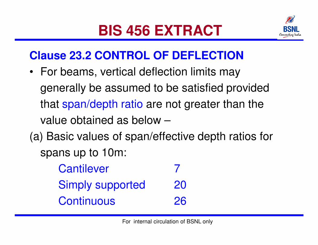
Clause 23.2 CONTROL OF DEFLECTION
• For beams, vertical deflection limits may
generally be assumed to be satisfied provided
that span/depth ratio are not greater than the
value obtained as below –
(a) Basic values of span/effective depth ratios for
spans up to 10m:
Cantilever 7
Simply supported 20
Continuous 26
For internal circulation of BSNL only
BIS 456 EXTRACT
Clause 23.2 CONTROL OF DEFLECTION
• For spans >10m, values in (a) may be multiplied by
10/span in meters,
Modification Factors are applied –
• Based on area & type of steel for tension
reinforcement (As per Fig. 4 of IS456)
• Based on area of compression reinforcement (As per
Fig. 5 of IS456)
• For flanged beams (As per Fig. 6 of IS456)
For internal circulation of BSNL only
BIS 456 EXTRACT
Clause 24.1 SLABS –Control of Deflection
• The provisions of 23.2 for beams apply to slabs also.
• For slabs spanning in two directions shorter of the two
spans to be used for span/effective depth ratios.
• For two-way slabs of shorter spans (≤3.5 m) with mild
steel reinf., span/depth ratios given below may
generally be assumed to satisfy vertical deflection limits
for loading class up to 3 kN/m2.
Simply supported slabs 35
Continuous slabs 40
For HYSD bars grade Fe 415 & Fe500, values given
above to be multiplied by 0.8.
For internal circulation of BSNL only
BIS 456 EXTRACT
26.5.2 Requirement of Reinforcement – SLABS
26.5.2.1 Minimum reinforcement
• Mild steel reinf. in either direction in slabs ≥ 0.15 %
of total cross sectional area.
• For high strength deformed bars ≥ 0.12 % of total
(Fe415/Fe500 bars) cross sectional area.
26.5.2.2 Maximum diameter
• The dia of reinforcing bars < 1/8th of total thickness
of slab
For internal circulation of BSNL only
BIS 456 EXTRACT
Requirement of Reinforcement – SLABS
26.3.3 Maximum distance between bars
�The horizontal distance between parallel main
reinforcement bars ≤ 3d or 300 mm
�The horizontal distance between parallel
reinforcement bars provided against shrinkage
and temperature ≤ 5d or 300 mm whichever is
smaller.
For internal circulation of BSNL only
SLAB DESIGN
Steps for Design of Slabs –
• Step 1: Selection of preliminary depth of slab
• Step 2: Calculate design loads, bending moments
• Step 3: Determination/checking of the effective and
total depths of slabs
• Step 4: Determination of areas of steel
• Step 5: Selection of diameter & spacing of
reinforcing bars
For internal circulation of BSNL only
BIS 456 EXTRACT
• Torsion reinforcement is provided at any corner
where the slab is simply supported on both edges
meeting at that corner.
• It consist of top and bottom reinforcement, each with
layers of bars placed parallel to sides of slab &
extending from edges a minimum distance of one-
fifth of the shorter span.
• Area of reinf. in each of these four layers is three-
quarters of the area required for maximum mid-span
moment in slab
For internal circulation of BSNL only
BEAM DESIGN
26.5.1.1 Tension reinforcement
a) Minimum reinforcement -
As = 0.85
bd fy
where
AS =minimum area of tension reinforcement
b =breadth of beam or the breadth of the web
d =effective depth of T-beam
fy =characteristic strength of reinforcement in N/mm2 &
b) Maximum reinforcement - The maximum area of
tension reinforcement not to exceed 0.04 bD.
For internal circulation of BSNL only
BEAM DESIGN
• Compression reinforcement
• The maximum area of compression reinforcement not to
exceed 0.04 bD
• Side face reinforcement
•Where depth of web in a beam >750 mm, side face reinf is
to be provided along the two faces.
•The total area of such reinf. should not < 0.1 percent of
web area and
•It shall be distributed equally on two faces at a spacing not
> 300 mm or web thickness whichever is less.
•Also to be provided in beams having torsion & with width or
depth >450mmFor internal circulation of BSNL only
BEAM DESIGN
Minimum shear reinforcement (Clause 26.5.1.6)
• Minimum shear reinforcement in the form of stirrups shall
be provided such that:
Asv = 0.4
bsv 0.87fy
Maximum spacing of shear reinforcement (Clause 26.5.1.5)
• The maximum spacing of shear reinforcement measured
along axis of member shall be < 0.75 d for vertical
stirrups and d for inclined stirrups at 45 degrees.
• In no case shall the spacing to be >300 mm.
For internal circulation of BSNL only
BEAM DESIGN
Steps for Design of beams–
• Step 1: Selection of preliminary cross sectional
dimension of beam
• Step 2: Calculate design loads, bending moments &
shear force
• Step 3: Determination/checking of the effective and
total depths of beam/ Revise if necessary.
• Step 4: Determination of areas of steel for flexure
• Step 5: Determination of shear reinforcement
• Step 6: Detailing as per IS 456 & IS13920
provisions
For internal circulation of BSNL only
FOUNDATION DESIGN
Design of Foundations – Important Considerations
• Foundations transfer loads from the building or individual
columns to earth. Foundations must be designed to
prevent –
• Structural Failure
• Shear failure of soil
• Excessive settlement &
• To minimize differential settlement
• Depth of footing is determined from the consideration of –
(a) Bending Moment
(b) One way shear
(c)Two way shear
For internal circulation of BSNL only
FOUNDATION DESIGN
Design of Foundations – Important Considerations
• To determine area required for proper transfer of total
load on the soil, the total load (the combination of dead,
live and any other load without multiplying it with any load
factor) need to be considered.
Total Load including Self Weight of footing
Plan Area of footing = -----------------------------------------------
Allowable bearing capacity of soil
Thickness of the edge of footing –
The thickness at the edge shall not be less than 15 cm for
footing on soils.
For internal circulation of BSNL only
FOUNDATION DESIGN
Design of Foundations – Important Considerations
Bending Moment (Reference Clauses- 34.2.3.1 & 34.2.3.2)
• The critical section for bending Moment is considered
at the face of column, Pedestal or wall.
Shear (Reference Clause 33.2.4.1)
• The critical section for one way shear is at the vertical
section located at a distance equal to the effective
depth (d) from the face of the column, pedestal or wall
of the footing in case of footings on soils.
For internal circulation of BSNL only
FOUNDATION DESIGN
Design of Foundations – Important Considerations
For one way action
For one way shear action, the nominal shear stress is
calculated as follows:-
Vuτv = -------
b.d
Where
τv = Shear stress, Vu = Factored vertical shear force
b = Breadth of critical section, d = Effective depth
τv < τc ( τc = Design Shear Strength of concrete based on % of
longitudinal tensile reinforcement refer Table 61 of SP-16)
For internal circulation of BSNL only
FOUNDATION DESIGN
Design of Foundations – Important Considerations
For Two Way Action (Punching shear )
Critical section for punching shear is at d/2 from the face of
column or pedastal
For two way shear action, the nominal shear stress is calculatedin accordance with clause 31.6.2 of the code as follows:-
Vuτv = ----------
b0.d
Where b0 = Periphery of the critical section
For internal circulation of BSNL only
FOUNDATION DESIGN
Design of Foundations – Important Considerations
Development Length (Reference Clause 34.2.4.3)
• The critical section for checking the development length in a
footing shall be assumed at the same planes as those
described for bending moment in clause 34.2.3 of code and
also at all other vertical planes where abrupt changes of
section occur.
Reinforcement –
� Minimum % of steel in footing slab should be 0.12% &
� Maximum spacing should not be more than 3 times
effective depth or 300mm which ever is less.
For internal circulation of BSNL only
DETAILING
• Reinforcing steel of same type and grade shall be
used as main reinforcement in a structural member.
• Simultaneous use of two different types or grades of
steel for main and secondary reinforcement is
permissible.
• The calculated tension or compression in any bar at
any section shall be developed on each side of the
section by an appropriate development length or end
anchorage or by a combination thereof.
For internal circulation of BSNL only
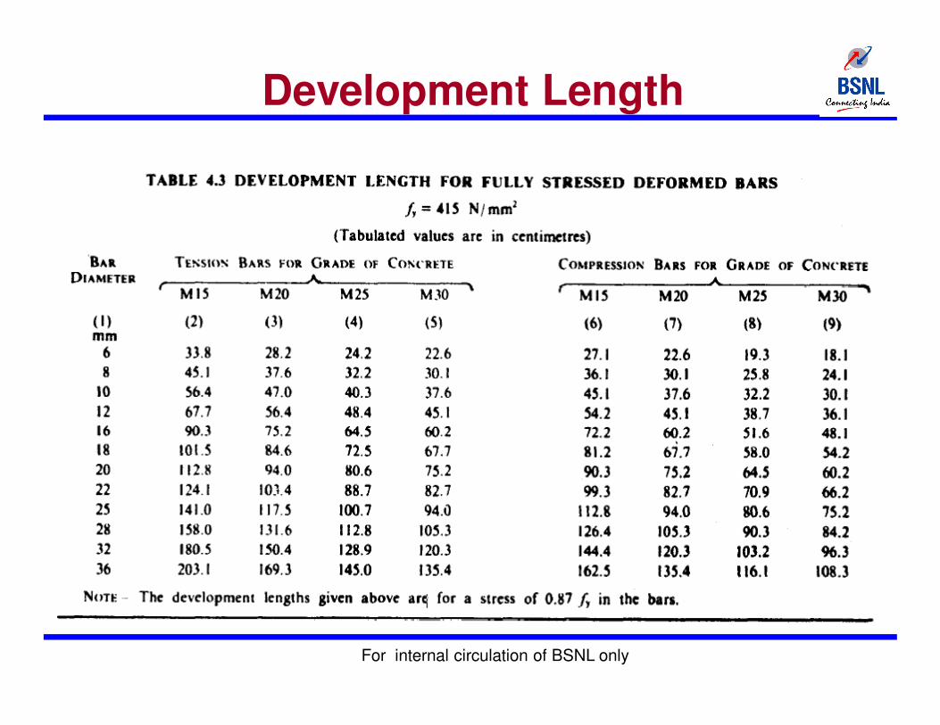
Development Length
Development Length of Bars
Ld = φσst /4τbd,
φ = nominal diameter of bar, τbd = design bond stress
σst = stress in bar at the section considered at design load
• Design bond stress in limit state method for plain bars in
tension is given in clause 26.2.1.1
• For deformed bars conforming to IS 1786 these values
are to be increased by 60 %.
• For bars in compression, the values of bond stress for
bars in tension is to be increased by 25 percent
For internal circulation of BSNL only
Development Length
For internal circulation of BSNL only
For internal circulation of BSNL only


