

ISIJ Internatlonal Vol 39 (1999) No. 1, pp. 1-9
Electromagnetic
tO Melt FlowConfinement Including the Dynamic Effect Due
Xu-RanZHU.Richard A. HARDING1)and John CAMPBELL2)Formerly AMRATechnologies Inc. Nowat MAYAHeat Transfer Technologies Ltd.. Montreal, auebec, CanadaH3ZIT3.E-mail: xuran,zhuCa: mayahtt,com 1) l.R.C, in Materials for High PerformanceApplications, TheUniversity of Birmingham,Birmingham, B152TT, UK. E-mail: R.A.Harding~v.bham.ac,uk
. , . ._. . .
2) l.R.C, in Materials for High Performance Applicationsand School of Metallurgy and Materials, The University of Birmingham, Birmingham. B152TT, UK.E-mail: J,Campbell.Met~L,bham,ac.uk
(Received on July 21. 1998.• accepted in final form on September11. 1998)
A 2 dimensional model has been developed to predict the free surface shape of liquid metal in anelectromagnetic field, in which the field calculations have been coupled with the free surface shape changeand the dynamic effect of the liquid metal flow. This has allowed the interactive phenomenain a corelessinduction furnace to be simulated comprehensively and resulted in satisfactory agreement between thepredicted and the measuredmeniscus shapes. Studies of the recirculating flow in molten aluminium haveshowninteractions of the meniscus shape with the flow field and therefore demonstrated the importanceof having detailed knowledge of the free surface shape in the electromagnetic processing of materials. Inaddition, the influence of the electrical conductivity and the skin effect in the induction coil on theelectromagnetic confinement and the melt flow have been analysed.
KEYWORDS:electromagnetic field; electromagnetic stirring; magnetic confinement; electromagneticprocessing of materials; coreless induction furnace; free surface shape; skin effect; sensitivity analysis;simulation.
l. Introduction
The electromagnetic (e,m.) processing of materials(EPM) utilises an e.m. field to generate eddy currents(and hence Joule heating in the metal charge) and toproduce Lorentz forces as a consequenceof the interac-tion between the induced eddy currents and the net e.m.field. EPMis widely used in molten metal processing andinvolves three basic phenomena:induction melting, in-
duction stirrlng due to the rotational part of the Lorentzforce and e,m. pressure due to the irrotational part ofthe Lorentz force. These effects results in coupling be-
tween the magnetic field, the e.m. stirring and the free
surface shape of liquid metals. Fortunately, in normalmetallurgical application~, the e,m, stirring does notinfluence the transport of the e,m, field since the mag-netic Reynolds numberis very small and hence diffusiondominates the convection; this decoup]es the e,m, field
from the flow fieid. Furthermore, the Lorentz forces arecomposedof a time-averaged part and a pulsating partchanging with time at twice the supply frequency. Hence,the situation can be further slmplified since it is wellknowni '2) that only the time-averaged part of the Lorentzforce contributes to the e.m. stirring because the inertia
of molten metal prevents it from reacting with thepulsating part of the Lorentz force. Nevertheless, theinteractive nature of the problem requires that all as-pects are considered since changes in one will result inalterations in the other two. This Is the case in many
1
practical metallurgical applications of EPMsuch aslevitation melting3) and semi-levitation melting.4) Insuch situations, the melt shape must be under controlwhich is determined by the coil configuration and theoperatlng parameters. As a consequence of the freesurface on the liquid metal which is subject to anequilibrium boundary condition, the focus of the inter-action is on the free surface shape since it determinesthe e,m. and stirring fields for a given coil and operat-ing parameters. Hencemuchattention has been paid5)
to the effect of the e.m. pressure.
2. Previous Investigations
Sneydand Moffatt3) developed a 'global' method forcalculating the free surface shape in e.m. Ievitation byconverting the equilibrium boundary condition (with-
out hydrodynamic pressure) into a variational energyprinciple with the constraint of melt volume conserva-tion. Most equilibrium shape calculations in levitationmelting have been undertaken with this method,6~10)coupled with e.m, field calculation using the mutualInductance method.11) However, only the surface elec-
trical currents along the melt boundary were usuallyinvolved, and few studies have comparedmeasuredandcalculated shapes due to the difficulty in measuring theshape of a levitated globule. In contrast to the globalmethod. Onishi and Etayl2) and Gagnoudet a!.8)
attempted to solve the problem using a local method
@1999 ISIJ

ISIJ International, Vol.
with constant segments, where the e.m, field was cal-
culated by taking the skin depth equal to zero. In this
approach, a fictitious irrotational velocity was intro-
duced together with its potential ~and the free surfaces
were iocally displaced during time with respect to the
normal velocity. Thefree surface shapewasso]ved using aGreen's function-Integral methodtechnique.
Evans and colleaguesl3'14) simulated the meniscusshapein e.m. casting using the mutual inductance methodto calculate the e.m, field, The peripheral surface ele-
mentswere movedradially inwards or outwards accord-ing to the pressure imbalance until equilibrium wasreached on the boundary. Following the work in twodimensions, the model was extended to three dimen-sionsls,16) to investlgate a rectangular cross sectlonbiilet. This methodmight only be suitable whenthe shapechange is minor, as in e.m, casting. It would be difficult
to predlct the meniscus at the top of a melt if it were to
change significantly from an initial cylindrical shape.
Lavers and his co-workersl7 ~ 19) were the first to use the
boundary element technique to calculate the meniscusshape in melting and casting by seeking equilibriumbetweenthe e,m. and hydrostatic pressures. Bhamidlpatiand El-Kaddah20) tackled the free surface shape in the
semi-levitation induction me]ting process by adjusting
the boundary horizontally. This assumed that the
magnetic field changed mainly in the radial direction
owing to the very thin skin depth. The predicted meltshapes showeda deformed peripheral surface and a flat
top surface with a sharp corner at their junction. Fugateand Huburg21) and Roy and co-workers22,23) used a'free movementmethod' to predict the free surface shapeof droplets andcolumnsof liquid sodium. Local pressures
on the free surface were comparedduring the search for
an equilibrium shape and the line segmentmethodwasused to discretize the geometry of the liquid domain.The e.m, field was calculated separately using a two-dimensional commercial packagebut the skin depth wasassumedto be zero and therefore no liquid flow couldhave resulted. Kawaseet al.24) developed a methodofmodelling the meniscus in a coreless induction furnaceby adjusting the meniscus contour according to an ex-perimentally-derived equation. This technique was thenused25) to calculate the free surface shape and e.m.field in a three-dimensional situation (induction skull
melting in a cold crucible).
It has been recognised3) that it is difficult to take the
dynamic pressure into account if the free surface is to
be calculated even when the fluid flow is laminar. Inthe above studies, the hydrodynamic pressure was usu-ally considered to be of only second order importanceand could therefore be neglected, so that only the
coupling between the e.m. field and free surface shapeand/or surface tension was involved. Very rarely, the
models have coupled the free surface shape with boththe e.m. field and melt motion. Another approach hasbeen to treat the free surface shape as a free boundaryof the fiow domain.26~28) In such cases, a pressureboundary condition at the surface was imposed and anIterative procedure was used to obtain the equilibrium
on the surface by coupling the free surface changewith
C 1999 ISIJ 2
39 (1999), No. 1
c~~D
Define initial shapeofmetal charge and coil
parameters Newcoordinates ofmolten metal surface
Calculate e.m. field,
Lorentz force andmagnetic pressure
Predict melt flow andobtain hydrodynamic
pressure
Fig, l
Are
pressures Noon the free surface
in balance?
Modify free surfaceshape
Yes
End
The flow chart of the model used to simulate the
electromagnetic confinement.
both the e.m, and flow fields. Rappazand Touzani26)treated the meniscus shape in an e.m. casting mould byassuming that it satisfied the Laplace-Young equation,in which the equilibrium must be reached between the
surface tension, the normal traction calculated from the
Navier-Stokes equations and an unknownconstant. InHenneberger's study of a coreless induction furnace,27)
the pressure boundary observed the Bernoulli equationand the finite difference method was used due to thesimple geometry of the crucible. Fukumoto et al.28)
discretlzed the transport equation of the free surface in
a laboratory scale crucible furnace using a first orderfinite difference upwind schemeto stabilise oscillations
on the free surface. Theeffect of melt flow on the meniscusprofile wasshownclearly by comparison with predictedmeniscus shapes without considering hydrodynamicpressures which produced apparently flatter meniscusshapes. This demonstrated that the melt flow must beconsidered in the meniscus shape calculation if accurateshapes are to be predicted.
In the present study, an earlier mode]29) to predictthe free surface shape of liquid metal in an e.m, field hasbeen further developed by considering the effect of the
melt flow in order to improve the representation of thefree surface shape. The ultimate aim was to develop amodel of the semi-levitation induction melting processto enable it to be used for melting reactive alloys, such
as titanium aluminides.30) Figure I showsthe flow chartof an iterative model which was developed to integratethe calculations of the e.m, field, the flow field and the
free surface shape of the liquid metal. Since the in-
teractions between these also occur in a coreless induc-tion melting furnace, a small furnace was used to studynumerically the e.m, confinement coupled with both the
e.m, and melt flow fields. The skin effect was con-sidered in all of the conductors, which differed fromprevious models in which the current was assumedto

ISIJ International. Vol.
be uniformly distributed in the ho]low coil (see for
example Sakaneet a!,13)). The model was validated bycomparing the measuredand computedmeniscusshapesand the flow field was then modelled to study its
relationship with the melt shape. Furthermore, a sen-sitivity analysis has been madeof the effect of theelectrical conductivity and current distribution in theinduction coil on the e.m, confinement and melt flow.
3. Mathematical Modelling
3.1. Assumptions
The mathematlcal modelling was based on thefollowing assumptions: (1) the e,m. field was harmonicand steady state; (2) the material characteristics wereconstant; (3) the electric field induced by the motion ofthe molten metal was negligible; (4) the displacementcurrent could be ignored; (5) the temperature distribu-tion in the molten metal wasuniform due to the strongstirring31)' and (6) the geometry of the calculation wastwo-dimensional and axisymmetrical.
3.2. Electromagnetic Field
The general equation describing the e.m. field (B) in
terms of the vector potential A(B=Vx A) is as follows:
aAVxVxA+pl(T
at=~J ..........(1)
in which ,t is the magnetic permeability, cr is the electrical
conductlvity, t is the time andJs the source (or impressed)current density. In two dimensional axisymmetrical cases,there is only one componentof A involved, namely Ao,and the Coulomb gauge (V • A=O) is automaticallyimposed. The governing differential equation of the
vector potential for skin effect problems can be thereforewritten as follows:
aAVA-ktcr
at = -ptJ ..........(2)
Slnce the current varies sinusoidaliy in any e,m, meltingsystem, the vector potential maybe conveniently rep-resented in phasor notation and separated into twoparts and written as follows:
A=Aej~t ..........(3)
with Abeing a complex variable amplitude having onlyspatial dependence, j=J- I and co the angular fre-
quency. Thecorresponding physical, time varying field is
then given by the real part of the complex. As a result,
Eq. (2) maybe expressed by the root meansquare value(A =A/•) and maytake the following form:
V2A-fa)~aA=-~J~.......
..........(4)
and an extra equation32) must be solved associated withEq. (4) to take into consideration the eddy current effect
in the induction coil tubing:
- -I~= (J,-,fcoaA)•ds......
..........(5)
where integration is over the cross section s of the coil
tubing and I~ is the measurable net coil current. The
3
39 (1999), No. 1
boundary conditions for the finite element model are avector potential of zero on the axis of symmetry andzero derivatives of the vector potential in the normaldirections of the far field boundary. Thus, the magneticflux density can be obtained from Eq. (3) and the rela-tionship B=VxA. In the case of linear magneticmaterials, the Lorentz force density f resulting from theinteraction of the induced currents and the applied (andinduced) magnetic field is:
f= -V I B2)+1(B•V)B.............,..(6)
2,l kt
It is well knownthat the first expression on the right ofEq. (6) is the irrotational part (conservative component)of f acting as the lifting force on the molten pool andthus creating the free surface (meniscus), and can beregarded as the gradient of the magnetic pressure, P~:
1P~=-B2..............(7)
2~
where Btakes the root meansquare value in the steadystate. The time-averaged Lorentz force density whichcauses the e.m. stirring in the melt is as follows, whereB* denotes the conjugate of Band Retakes the real partof the complex:
ft= I Re(JXB) ..........(8)
23.3. Electromagnetic Stirring
Analysis of the electromagnetically driven liquid metalflow basically involves the formulation and examinationof the following equations:
(i) the governing equations of the e,m, field;
(ii) the equation of continuity:
V•u=0 ................(9)
where u is the velocity;(iii) the incompressible time-averaged turbulent
Navier-Stokes equation embodyingthe effect of the e.m.and other forces on the motion:
pu'Vu= -Vp+v'(n.ffVu)+ft+pg ........,(10)
in which p is the pressure, g the acceleration due togravity, p is the mass density and n*rr the effectiveviscosity. The latter is introduced to include the influenceof fiuctuating terms in the time-averaging process and is
defined as:
n*rr =n~+n ..........(1 l)
wherethe first term on the right handside is the molecular(i,e. Iaminar) viscosity and the second term is the eddyviscoslty causedby the turbulent nature of the fluid flow.
There are a numberof ways to calculate the turbulentflow, amongwhich the ke turbulence model33) has beenmost frequently used, where k is the turbulent energyand 8 its dissipation rate. Theboundaryconditions whichwere required to complete the statement of the problemwere zero velocity at the melt/solid interface, zero shearat the free surface and the existence of symmetryaboutthe centreline.
@1999 ISIJ

ISIJ Internationai, Vol. 39
3.4. Free Surface ShapeCalculation
In principle, two constraints govern the melt shapechange. The first is the equilibrium condition of the free
boundary, which can be approximated by taking the
Bernoulli equation along a stream line5,34):
pgh=P~+ pu2+Ky+C.....
..........(12)
where h is the height of the point under considerationmeasuredfrom the top of the molten volume, K is the
sumof the principal curvatures of the free surface, y is
the surface tension and C is the integration constant,normally assumed to be zero. The other restriction
governing the shape change is the conservation of the
melt volume (Q):
6Q=0 ................(13)
Anymovementof a surface point from the equilibriumstate results in a local pressure imbalance, 9~, given by:
9t=P~+K~y+ p(u~)2-pgh ...........(14)
where P~. K- and u~ are the values at the imbalancingpoint of the surface. By substituting Eq. (12), this
becomes:
1p[(u~)2-u2] ....(15)9?= (P~ - P~)+ (K~y- Ky) +-2It was assumedthat the surface tension and dynamicpressure remainedconstant during eachpair of sequentialiterations where the shape change was very small. Thepressure imbalance wastherefore solely due to the changeof magnetic pressure, so that Eq. (15) could be reduced to :
~t*=P~ -P~ ..............(16)
WhenEq. (12) cannot be satisfied at any given pointalong the free surface as a result of a local imbalance,~?, between the metallostatic pressure, surface tension,
hydrodynamic and magnetic pressures, there will be ahorizontal displacement of the free surface from its equili-
brium position. This occurs becausethe vertical gradientof the e.m. field along the free surface is muchsmallerthan that in the radial direction due to the very low skin
~~Z~~:depth, 8 (= 2/klco(T), resulting from a high frequencycoil current and a metal charge of high electrical con-ductivity. By expanding P~, it can be expressed in
terms of the equilibrium pressure P~20):
ap~Ar
.................(17)P~ P~+
ar
where A,' is the radial displacement and ap~/ar is the
pressure gradient on the surface. So the radial dis-
placement can be calculated from the following equa-tion:
Ar~7
..........(18)
ap*la,'
while
(1999), No. 1
Probe mountedon aX-Y table
Meniscus
""**
122 ~,
*-~
@1999 ISIJ 4
~~~1 f~~~1~~~ ~~~l~~i~ ~~~I~~~1 ~~~~~ ~~~]f~~I [~~1~~~ ~~~I 160c94~~~ ~~~l\\~~~! E~~l
~P~)~~~~ • ~~:~~~I ~~~l,~~~~] ~~~l~~~ ~~~1
13turn copper Non-conductingMolteninduction coil crucible
aluminium
Fig. 2. The experimental apparatus for measuring the
meniscus shapes. (dimensions in mm)
Table l. Physical properties of materials used in the
modelling.
Property Electrical Massdensity Viscosityconductivity p(kg/m3) Thn (kg/ms)
Material (~o (S/m)
Aluminium 4.03 x l06 2370 l 325 x 10-4
(7000C)
Copper(600C)
5.08 x 107
=- *._
zapm I aB I aB eB
B B +B .
(19)
~ *ar p ar ar er
By replacing 9?* in Eq. (18) with ~~ in Eq. (14), all aspects
were therefore included in determining the local pressureimbalance which leads to the free surface displacement,Ar, in Eq. (18). Themethodof surface discretisation andshape modification has been detailed by the authorselsewhere.29)
4. ComputerModelling
An iterative procedure, as shown in Fig. l, wasdeveloped for repeatedly calculating the e.m, field, meltflow and modifying the free surface shape in the furnaceshown in Fig. 2. The physical properties used in thecalculations are listed in Table 1. AUNlXshell script
was created to run two commercial software packages(OPERA-2dfrom Vector Fields Ltd, Oxford, UKfor
e.m. field calculations and CFX-3dfrom AEATechnol-
ogy, Harweil, UKfor fluid flow calculations) outsidetheir graphic environment, to link the packageswith the
program for the free surface shapecalculation developedin the present work, and to control the entire iterative
process. The surface tension was not considered in Eq.

ISIJ Internationa[, Vol. 39 (1999). No. 1
~~Nl:~
O
O~~~O'~
~
20
10
o
-lO
-20
Current,
AMeasured
shapeCalculatedwithout Pu
Calculatedwith Pu
177 e255 Cl
368 A
A
e
,Initial shape 1 't
*e
1
\
~~N!::O
e,)
O::~~~O.~,1)
>
20
lO
o
-10
-20
Current,
A225283375
Calculated Calculatedwlthout Pu with PL*
O IO 20 3O 40 50 O IO 403020
Radial position, r (mm) Radlal posltion, r (mm)
(a) Melt weight I . I kg. (b) Melt weight I.5 kg.
Fig. 3. Comparisonbetweencalculated and measuredmenisci in a coreless induction furnace.
50
(12) in the present calculations due to its trivial
contribution to the pressure imbalance.29) At the start
of the calculation, it wasassumedthat the metal charge
wasmolten and that it had an initially cylindrical form.The e.m, field was firstly calculated for this initial
charge shape. This led to calculations of the magneticpressures and the turbu]ent fiow in the melt. Themoltenmetal shapewasthen modified according to the pressureimbalance on the surface. This provided a set of newco-ordinates for the next calculations. The equilibrium
wasconsidered to have been effectively reached and thecalculation to be complete whenthe pressure imbalanceat every point along the free surface was less than I olo
of the hydrostatic pressure of the original melt height,ho, i.e. when:
l9~ 1~(pgho)/lOO......................,
(20)
The calculations were carried out using a Silicon
Graphics workstation and about 30 iterations werenecessary to obtain an equilibrium shape of the moltenpool from the initial shape.
5. Validation
The calculations of the e.m, field and melt fiow werevalidated using published data for a coreless inductionfurnace.35) In order to validate the free surface shapecalculations, measurementswere madeof the meniscusof molten aluminium in asmall coreles sinduction furnacewith a frequency of lOkHz, Fig. 2. A probe wasmadefrom two closely spaced O.3 mmdiameter Ni-Cr wires
and connected to a circuit containing a battery and bulbwhich wascompleted whenthe probe touched the moltenmetal surface. Theprobe wasmountedon a carrier whichenabled it to be movedvertically and horizontally bymeasurable distances so that the meniscus shape could
be obtained. The initial load level of the metal charge in
the furnace was obtained by measuring the surfaceposition immediately after cutting the power supply tothe furnace. Coil currents were measuredby encirclingthe furnace coil leads with acurrent waveformtransducer(a Rogowski coil) connected to an oscilloscope. Themeasurementerrors were estimated to be +0.5 mmforthe menisci and +2o/o for the coil current. Themeniscusshape wasmeasuredfor different coil currents and meltweights. Whencarrying out the meniscusmeasurements,only very small oscillations were observed on the free
surface which supports the commentof Garnier andMoreau2) that mediumfrequency magnetic fields canlead to stationary free surfaces.
6. Results and Discussion
6.1. Meniscus ShapesFigures 3(a) and 3(b) compare the calculated and
measuredmeniscusshapesfor two melt weights and threeapplied currents for each weight. It can be seen thatsatisfactory agreement was obtained, particularly whenthe effect of hydrodynamic pressure was taken into
account. At worst, the discrepancy was within - 2mmwhich was similar to the measurementerror. It is clearthat with the samemelt weight, the meniscus heightincreased with increasing coil current and, at the sametime, the junction betweenthe melt, crucible and air was10wered. The inclusion of the hydrodynamic pressure,P~, resulted in the lower part of the meniscus beingpushed radially inwards and the meniscus height in-
creasing at the centre of the crucible. Fukumoto etal.28) haveshowna similar changewhenP~wasincluded.
Figures 4(a) and 4(b) comparethe melt heights calcu-
lated with and without the contribution of the hydro-dynamic pressure, in which dh is the increase in melt
5 rc+).c: 1999 ISIJ

IS[J International, Vol. 39 (1999), No. 1
50
40
~~_30
~i,eJO*
e)J::
~,~) 20l:~
q,~{
10
o
[] dh' measured-- +-- dh' without flow
--h dh' With flow lo-e---dh
'Without flow
[ot /- o- -dh
'With flow I "'
tol
/ 'li~L:::::il:0256
// I~
/ /C2 o,o00256 '
\ / '/~(lo./" C2 o,o00205
/'// "/'/
.
p"l'
. Idd'r~
150
~~~::~)
'e)
~~
::,
L)
r:~
~)~:
50
40
30
20
10
o
c] dh' measured--+-- dh' Without flow
'-~ dh' With flow
-e--dh 'Without flow f)
/- o- -dh
'with flow J'
10L / '
//./"
/1.1~~
/c/'~/h'
~::ii:~::::l "// "' C2 OOO0146'o. /l 'e
'i':/ *__1F/'// '
_'r' ~
Fig. 4.
200 150 250 300 350200250 300 400350Coil current, I (A) Coil current, I (A)
(a) Mass= I I kg (b) Mass= 1.5 kg
Changein the meniscusheight with coil current and approaches to calculating the meniscus shapes.fitted to d/7*.*= C1 • I+ c2 ' P.
400
Curves
height comparedwith the initlal load level and dht.t is
the total free surface height from the top of the meltto the contact point between the crucible and the melt.
Thehydrodynamicpressure contributed to the meniscusheight which generally resulted in a closer matchbetweenthe measuredand calculated heights. Figure 4demon-strates that it wasmorecrucial to consider P~as the coil
current increased. The total free surface height, dht.t'
shows a similar change but the effect of P* was evenmoremarkedwith increasing coil current. With the samecrucible position, Fig. 4showsthat there wasa tendencyto obtain moresignificant menisci in a I . I kg molten poolwith lower currents than in a I.5 kg molten pool withhigher currents. This indicates that there is a stronginteraction between the e,m. forces and the melt shapesand implies that electromagnetic confinement would beeasier for a smaller amount of metal. The followingequation of best fit wasobtained for the curves in Figs.
4(a) and 4(b).
dh*ot=CI x I+C2 X 12... .........
(21)
where C1 and C2are coefficients having the values givenin Fig. 4. The relationship between the coil current andthe levitated meniscus height can usually be effectively
estimatedl3,35) by the meniscus height being propor-tional to the square of the coll current as observed byFukumotoet a!.28) Nevertheless, a linear term wasaddedin Eq. (21) to improve the fitting as it wasenvisaged thatthe coil configuration, crucible shape, Ioad level, relative
positions of coil andcrucible andhydrodynamicpressurewould all affect the confinement.
6.2. Flow Field
Figures 5(a)5(f) illustrate the time-averaged fiow fields
(calculated using a 20 x 30 finite difference mesh) withdifferent meniscus shapes. In half of the meridian planeof the furnace, the classical two opposite flow loops werewell developed with higher currents, but the upper loop
wasquite small and the meniscus wassmaller whenthe
@1999 ISIJ 6
current was low, Flgs. 5(a) and 5(d). This demonstratesthe influence of the meniscus on the flow field. Taberletand Fautrelle31) observed that variations in the coil
current did not influence the flow pattern in inductionfurnaces, whereas the amplitudes of the meanvelocities
were proportional to the magnitude of the coil current.These observations appear to agree well with the pre-dictions of the flow in the present coreless inductionfurnace, as shown in Fig. 5. It is interesting to note,nevertheless, that a higher coil current which resultedIn a blgger meniscus (see Fig. 3) increased the dimen-sions of the upper recirculating loop, as shownin Figs.5(a)-5(f). This demonstrates howthe melt shape affects
the melt flow. It follows logically that, in order to modelthe flow correctly, the meniscusshapemust be accuratelyrepresented.
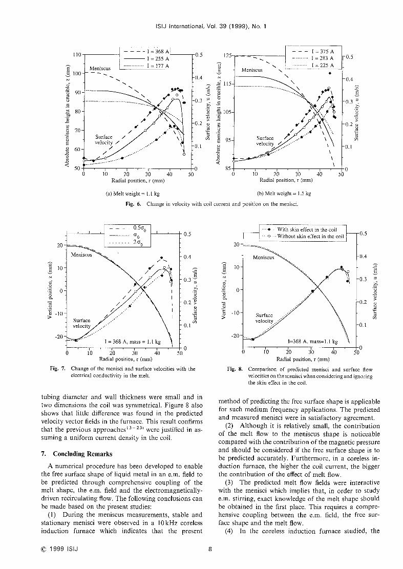
The magnetic pressure was much larger than thedynamlcpressure due to the flow and there wasthereforequite a big difference in their contribution to the meniscusheight, as can be seen in Fig. 4. Figures 6(a) and 6(b)illustrate the predicted menisci with different currentsand the surface velocities on these menisci and showthathigher coil currents usually produced taller melt domesand higher surface velocities. This explains why the hy-drodynamic pressure contributed more to the meniscusheight as the current increased, as shownin Fig. 4.
6.3. Electrical Conductivity
Since the model required data on the electrical con-ductivity of the materials in the liquid state but onlylimited data of uncertain reliability were available, thesensitivity of the e.m. confinement and melt fiow on theelectrical conductivity of the melt charge wasanalysed.
Figure 7showsthat the meniscusshapesdid not changesignificantly with the electrical conductivity, a. With achange from O.5cro to 2cro (where (TO is the generally
accepted value for liquid aluminium at 700'C, see Tablel), the resulting free surface shapes could hardly bedistinguished from each other. However, Fig. 7 also

ISIJ International, Vol. 39 (1999), No. 1
:\:\\\~ \' ////!~ }!
1////////:-~~'~'~\\1
!i///////-~ \ i11J////-\\iii///'1ittlllldllll IL\ ' ///\\ \ \ ~//
~\\ \ \~'~/:'~/~P
l\\ \\\\~/'~~:/'~
\~\ \\~'~\ \ \\\~lr1 \ \~~-
! / //-f I / f ////~
11\\\\\\\\\, ,
' +'\\\\\\~~~_ \' '''
i//j//~i~i/j4;:////"/r-~ 1lf
J1 ii! f/ ' 'll71Ji
}\\);~'/~tt tt\\~4\
\\\\~~~\\\\-___,~.
~~\\\~ "
~~+~~
/ llf!!//'-Ifl(1(1!(/j/{-~;
l\\\\\\\\\~]\\~
///~~;
1/{(!(ii(~;Li:r: !/1it 1!_i /=~L--//
~\\lA\\
~\\\\h\ \\~'-~
(a) Maximumvelocity: 0.22 ms-1 (b) Maximumvelocity: 0.35 ms-l (c) Maximumvelocity: 0.47 ms-l
t ' / / ////=11]Iff!f!f"i\l I \ ~\\\\~=1/r/
+ * +~~ =/// '
" "///////' ~ ' I
I I ///////" ' + 11htl
ll//j/////-~\~iii!!1!flll'~\\iIIlill!!11'~~jl
llllltltt\\~'~ ~-ll {11~\\\\\~
l i t \ \\\\+_-/~
I ~h\ \\+~~"L ~ \++*
I j / //'-TI i ! ! f ////li~il\11\11'.\
* +~\\\\\\~~~=/// l'
_\ii / / /////-~-~
i!!i /////'-~
!IlllIIII'~;li'
I
}1 }\ (\ (\ i\::~i://;~~
I t \ \ \\+**'1~++++~-
i f //-f!f////-IiIi!////lllJfJf!//~~_,~~~
iI\\\\\\\\\_~:=;!l~\\\\\\\~~-
~\ \!f///////-\\ l!!i///////~_\ \
Itt'~I~
\\\J\\\\\\-~,~"'.
It~\\\\=I \ +++~~
(d) Maximumvelocity: 0.22 ms-1 (e) Maximumvelocity: 0.29 ms-1 (D Maximumvelocity: 0.43 ms-l
Frg. 5. The velocity fields of the molten aluminium in a coreless induction furnace: (a) I= 177A, mass=1,1 kg;
(b) I=255A, mass=1.lkg; (c) I=368A, mass=1,lkg; (d) [=225A, mass=1.5kg; (e) I=283A,mass= 1.5 kg; (D I=375A, mass= I.5 kg.
The dimensions of the molten pools are shownin Figs. 3(a)3 (D-
shows that, as a was increased, the location of the
maximumve]ocity on the menisci movedoutwards as aresult of the decreased skin depth. A Iower (r generally
produced a higher surface velocity at all points on the
meniscus, but the difference was relatively small. Thisimplies that the uncertainty in cr doesnot greatly influence
the accuracy of the prediction. For example, commer-cially pure aluminium or even aluminium alloys can betreated as chemically pure aluminium In the simulation.
The significance of this from the engineering viewpointis that e,m. confinement can be satisfactorily modelledfor novel materials such as titanium aluminides, for
which the exact value of (T is unknown.
6.4. Skin Effect in the Coil
As reviewed above, the skin effect in the induction coil
7
has been neglected in previous simulations by assuming
a constant current density (J~) in the coil tubing crosssection (Eq. (4) nowhas only one unknownvariable A).
It wasenvisaged that this maycause someerrors in the
modelling and therefore the skin effect was consideredin all the present calculations by applying the measurablenet coil current in Eq. (5) and solving Eqs. (4) and (5)
together as nowJ~ is also unknown.However, as shownin Fig. 8, the present work has shownlittle difference in
the predicted menisci in the coreless induction furnace
when the skin effect In the induction coil was replaced
by a constant current density. Certainly, the currentdistribution in the coil differed in that a non-uniformcurrent density distribution wasproduceddue to the skin
effect, but the resulting e,m. field in the melt remained
very similar. The reason for this maybe that the coil
@1999 ISIJ
ISIJ International, Vol. 39 (1999), No. 1
E8N4)
!)~~o~~
~:~QO~::
~l::
o~oi:;
O~:)
llO
1OO
90
80
70
60
50
II = 368 A~
o
Surfacevelocity /
//
/
lO 20 30Radial position, r (mm)
(a) Melt weight = 1.1 kg
Fig. 6.
40 50
05
0.4
~0.3 ::~
~:;
oot)
>02 Q)
~~
O, l
l25
~ENc~) I15
~:)
o:s
oc:
~::~o 105O~:
;s
vl::
e'n~ y5cL)
~I~;
"~:3
85
\ \Meniscus
Surfacevelocity
l'
d ,...,.,.
\
- - I=375AI = 283 AI = 225 A
0.5
/
\
l'
\\
/
IF
,J
l~
// .\/
,,*\
1'.'
\\\
\~
\
~
\
0.4
~0.3 :'
>:;
vo~5>0.2 ,L)
vc:~
:sCl)
O. 1
o IO 20 4030Radial position, r (mm)
(b) Melt weight = I.5 kg
Changein velocity with coil current and posltion on the menisci.
50o
~~Nl:~
Q
ot~~~o~>
20
10
o
-10
-20
_ _0.5(;o
ao2ao
Meniscus
Surf acevelocity
~~~~
b/
//
,/
/ ,
.,r
/ /
1" '
e/'~
o .\.
..
(p'IL
1:
illl
I 368 A mass= 1.1 kg
o lO 20 4030Radial position, r (mm)
5
0.5
0.4
~~0.3
:s
~~
vo0.2 ~
(D
vc~
~'cl)
O. l
o
~~r~l
C:~
O
Ol~~~Oe)
>
20
lo
o
-10
-20
•dF-•- With skin effect in the coil
•-e-- Without skin effect in the coil:iLi
Meniscus "'
Surfacevelocity...
I=368 A, mass=1.1kg
Fig. 7.
o
o,o
6
o 1O 20 30Radial position, r (mm)
Comparison of predicted menisci
the skin effect in the coil.
40 5o
0.5
0.4
~03 :s
~:;
~)
oG)
0.2 8L~~a5
~::Cl)
O, l
Changeof the menisci and surface velocities with theelectrical conductivity in the melt.
tubing diameter and wall thickness were small and in
two dimensions the coil wassymmetrical. Figure 8also
shows that little difference was found in the predictedvelocity vector fields in the furnace. This result confirmsthat the previous approachesl3~23) were justified in as-suming a uniform current density in the coil.
7. Concluding Remarks
A numerical procedure has been developed to enablethe free surface shape of liquid metal in an e.m. field tobe predicted through comprehensive coupling of themelt shape, the e.m, field and the electromagnetically-driven recirculating flow. The following conclusions canbe madebased on the present studies:
(1) During the meniscus measurements, stable andstationary menisci were observed in a lOkHz coreless
induction furnace which indicates that the present
Fig. 8.
o
and surface flowvelocities on the menisci whenconsidering and ignoring
methodof predicting the free surface shape is applicablefor such mediumfrequency applications. The predictedand measuredmenisci were in satisfactory agreement.
(2) Although it is relatively small, the contributionof the melt flow to the meniscus shape is noticeablecomparedwith the contribution of the magnetic pressureand should be considered if the free surface shape is tobe predicted accurately. Furthermore, in a coreless in-
duction furnace, the higher the coil current, the blggerthe contribution of the effect of melt flow.
(3) The predicted melt flow fields were interactive
with the menisci which implies that, in order to study
e.m. stirring, exact knowledgeof the melt shape shouldbe obtained in the first place. This requires a compre-hensive coupling between the e.m. fieid, the free sur-face shape and the melt fiow.
(4) In the coreless induction furnace studied, the
O1999 ISIJ 8

ISIJ International, Vol. 39 (1999), No. 1
meniscus height had a second order polynomial rela-
tionship with the applied coil current.(5) Although the electrical conductivity of the melt
charge infiuenced the flow velocity slightly, It had almost
no impact on the e.m, confinement. Thusexact data for
the electrica] conductivity or its temperature dependenceare not necessary whenmodelling e.m. confinement.
(6) In a coreless induction furnace, the skin effect
in the induction coil tubing had negligible effect on the
e,m, confinement and melt flow.
Acknowledgements
Oneof the authors (XRZ) would like to express his
gratitude to the Sir Y. K. PaoFoundation (HongKong),the State Education Commissionof China and the British
Council for provision of the financial support by theSino-British Friendship Scholarship Scheme(SBFSS).Theauthors would like to thank Professors M. H. Lorettoand I. R. Harris for the provision of experimental andcomputing facilities and the staff at Vector Fields Ltd.for invaluab]e discussions.
l)
2)
3)
4)
5)
6)
7)
8)
9)
1O)
l l)
l2)
REFERENCESD. J. Mooreand J. C. R. Hunt: Metallurgical Applications ofMagnetohydrodynamics, ed, by H. K. Moffatt and M. R. E.
Proctor, The Metals Society. London, (1984), 93.
M. Garnier and R. Moreau: J. F!uicl Mech., 127 (1983), 21 l.
A. D. Sneydand H. K. Moffatt: J. Fhiid Mecll., I17 (1982), 45.
N. El-Kaddah, T. S. Piwonka and J. T. Berry: USPatent No.5033948, (1991).J. D. Lavers: ISIJ In/., 29 (1989), 993.
A. Gagnoudand I. Leclercq: IEEET,'ans. Mag,1., 24 (1988), 256.
A. Gagnoudand I. Leclercq: IEEET,'ans. Mag,1., 24 (1988), 573.
A. Gagnoud,J. Etay and M. Garnier: T,'ans. I,'0,7 Slee/ h7s!. Jpn.,
28 (1988), 36.
A. Gagnoudand J. P. Brancher: IEEETra,Is. Mag,1.MAG-21
(1985), 2424.
N. El-Kaddah and F. A. Acosta-Gonzalez: Casting of Near NTet
ShapeProducts, ed, by Y. Sahai el a!.. TheMetallurgical Society,
(1988), 423.
R. F. Dudley and P. E. Burke: IEEET,'ans. Indusl. ApP!.. IA-8(1972), 565.
A. Onishi and J. Etay: Eng. Ana/. Bou,7d. Ele,77,, 10 (1992), 225.
13)
l4)
15)
l6)
17)
18)
19)
20)
21)
22)
23)
24)
25)
26)
27)
28)
29)
30)
31)
32)
33)
34)
35)
J Sakane. B. Q. Li and J. W.Evans: Metal!. T,'a,7s B, 19B(1988),397.
B. Q. Li and J. W. Evans: IEEET,'ans. Magn., 25 (1989), 4443,B. Q. Li and J. W. Evans: Casting of Near Net ShapeProducts,ed, by Y. Sahai et a/.. The Metallurgical Society, (1989), 41 l.
D. P. Cook. S. Nishioka and J. W. Evans: Me!cl!!. Maler. Trclns.
B, 26B (1995), 1271.J. D. Lavers and M. R. Ahmed:Casting of Near Net ShapeProducts, ed. by Y. Sahai et a!.. TheMetallurgical Society, (1988),
395.J. D. Lavers and M. R. Ahmed:IEEET,'ans. Mag,1
,24 (1988),
2521,
J. D. Lavers and P. P. Biringer: IEEET,'ans. I,rdust,y App/., 25(1989), 495.J. R. Bhamidipati and N. El-Kaddah: Magnetohydrodynamicsin Process Metallurgy, ed. by J, Szekely et a!.. The Minerals.Metals &Materials Society, (1991), 69D. W.Fugateand J. F. Hoburg: Meta!!. T,'clns. B, 24B(1 993), 171.
S. S. Roy, A. W.Cramband J. F. Hoburg: Meta!!. Mate,'. T,'ans.
B, 26B (1995), I i91.
S. S. Roy. A. W. Crumb. J. F. Hoburg and B. Lally: Meta!!.
Mater. Trans. B, 26B (1995), 1183.
Y. Kawase. Y. Murai and N Hayashi: T,'c,ns. IEICE J!'n.,
J72-D-II (1989), 271.
Y Kawaseand T. Yamaguchi: IEEETrans. Mclgn., 29 (1993),
l554.J. Rappazand R, Tou7~ani: Light Metals 1992, ed, by E. R.Cutshall. TheMinerals. Metals &Materials Society. (1991), 1269.
G. Henneberger. Ph. K. Sattler, D. Shenand W. Hadrys: IEEETrans. Magn., 29 (1993), 1589.
H. Fukumoto, Y. Hosokawa, K. Ayata and M. Morishita:Magnetohydrodynamicsin Process Metallurgy, ed, by J. Szekelye! cl!.. The Minerals, Metals & Materials Society, (1991). 21
.
X. R. Zhu. R. A. Harding and J. Campbell: AJ;1;!. Mat/1. Moc!e!.,
21 (1997), 207.
R. A. Harding and X. R. Zhu: Electromagnetic Processing ofMaterials. Proc, of Int. Cong.. Paris. May, (1997), l, 165.
E. Taberlet and Y. Fautrelle: J. F!uic! Mec'/7., 159 (1985), 409.
A. Konrad: IEEET,'ans. Mclgn.. MAG-21(1985), 1805.
B. E Launderand D. B. Spalding: C0,1lput. Metlloc!s App!. Mec'h.
Eng., 3(1974), 269,
A. J. Mestel: Metallurgical Applicatlons of Magnetohydrody-namics, ed, by H. K. Moffatt and M. R. E Proctor, The MetalsSociety. London. (1984), 197.
X. R. Zhu: PllD Dissertation. The University of Birmingham,UK. (1997).
9 C 1999 ISIJ


