

Electronic Over Current Relays
Electronic Over current Relays
Electronic Under current Relays
Electronic Voltage Relays
Other Protection & Monitoring Devices
Current Transformers

UL
CE
ABS
SEV
KR
CCS
TÜV
CSA
RINARegistroItalianoNavale
CanadianStandardsAssociation
TÜVGermany
ChinaClassificationSociety
KoreanRegister ofShipping
AssociationSuisse DesElectriciens
AmericanBureau ofShipping
CommunityEuropean
UnderwritersLaboratoriesInc
1981 SAMWHA Engineering Co., Ltd incorporated1988 SAMWHA R&D Center established1990 The 2nd factory completed in Iksan, Korea1990 Recognized as the Advanced Technology Small& Medium
Sized Company by the Korean Ministry of Trade and Industry1993 SAMWHA Electric(Tianjin)Co., Ltd.
established in Tianjin, China1994 SAMWHA Electronics (Beijing)Co., Ltd.
established in Beijing, China1995 SAMWHA R&D Center building completed in Eumsung, Korea1996 SAMWHA Engineering (Vietnam) Co., Ltd.
established in HCMC, Vietnam1997 Reach to 5millions of EOCR production1997 ASIC(Application Specific Intergrated Circuit) Chip Developed1997 Registered to KOSDAQ(Registered No. 507)1999 Approved to New Technology by Korean Government for
ASIC Chip Applicable EOCR-3D&FD Series Product(Registered No. 5)
2001 Recognized Export Leading Company by Korean Government2002 SAMWHA EOCR Ltd. Established
Approved by BM TRADA(U.K)Approved Date 1995. 8. 30
ISO 9001 Certificate
ISO 9001 Certificate
General Information
EOCRSS
EOCRSP
EOCRDS
EOCR3D
EOCRFD
EOCRPMZ
EOCRPFZ EVRApproved
Company History
1985 The Presidential Prize of 85 National Invention Awards1986 The Ministerial Prize of National Invention Promotion Awards
The KYUNGHYANG Energy PrizeThe Ministerial Prize of Korea Electronics ExhibitionThe Golden Prize of 86 National Invention Awards
1989 The Order of Industrial Service MeritThe Grand Prix of 89 National Invention Awards
1990 The Bronze Prize of 91 National Invention Awards1991 The Venture Company of 19911994 The Electric Industry Development Prize of KOMA
The Order of Industry Service Merit1995 The Tower of Export1998 UN WIPO Prize1999 The Order of Industrial Service Merit
Domestic Awards
1989 The Silver Medal of INPEX Pittsburgh1990 The Silver Medal of Geneva International Invention Award1992 The Golden Medal of De L Invention De Paris1993 The Bronze Medal of Beijing International Award1998 The Golden Medal of IENA98. Germany
International Awards
Worldwide Service Network
TQCS Quality System
Reliability & Safety
Register Applied for No Register Applied for No
29 6 35 5 0 5 40
20 7 27 0 0 0 27
25 0 25 0 0 0 25
34 11 45 14 3 17 62
108 24 132 19 3 22 154
Patent
Utility Model
Design
Trade Mark
Total
Domestic OverseasTotalItem
Intellectual Property
TotalQualityCustomer’sSatisfaction

EOCR Setting Patlem / Motor Running Current (3DD & FD Series)
0560
100:05200:05300:05400:05500:05600:05
0.5 ~ 65.0 ~ 6010 ~ 12020 ~ 24030 ~ 36040 ~ 48050 ~ 60060 ~ 720
kW0.755.522375595110150
HP1
7.5305075125150200
4.82693160230360440570
kW1.5223775132190220300
HP23050100175250300400
4.2 / 3.649 / 4684 / 73
163 / 141263 / 227376 / 325423 / 390602 / 520
3.55.5~14
38100250325400500
2867130240430495565625
Cable SizeThickness
( )AllowableCurrent(A)
Current(A)
Current(A)
Current Setting Range (Adjustable)
(A)TYPEAC380/440(V)AC220(V) Remark
Assemblewith
External CT
Built-in CT(Standard type)
Capacity of 3 Phase Motor (kW/HP)
EOCR Type Table for 3phase Motor
Option-1. Looping (Protect smaller current by looping option)Some motor size may require one-third or one-fourth of particular EOCR current range. Theseinstallations can be accommodated by looping the motor wire 2 or 3 times through the integral currenttransformers of the EOCR. This reduces the number and type of relays inventoried for spare purposes.Each additional loop will increase the current measured as indicated by the following chart.
05 Type
Looping Option
Current SettingRange(A)
0.5 ~ 6 0.25 ~ 300.17 ~ 200.12 ~ 1.500.10 ~ 1.20
Time of Passing (#)12345
No. of Loops(#)
0 Fig 1 1 Fig 2
234
Fig 1 Fig 2looping Option ( 2-Loop )Straight-through-Wiring
05 Type60 Type
Ext. CT Option
0.5 ~ 6005.0 ~ 60010 ~ 12015 ~ 18020 ~ 24030 ~ 360
Current SettingRange(A)
NILNIL
100 : 5150 : 5200 : 5300 : 5
Current Ratio of Ext. CT
External 3CT Option External SR-CT Option
Option-2. External Current Transformer Option (Ext. CT option protect bigger current)Ordering option - 05 type of each model fitted to an external current transformer can achieve higher ampere ranges.
1
Over Current Relay

NVR(No Volt Release)/On(N Type)Fail-safe
D-TIME(Delay Time): When starting the motor, it s current is increasing 5 to 8 times of rated current and its starting time
is different according to the load of motors. D-Time knob(Mode) has a function to delay
the trip during starting period even if starting current exceeds over preset over-current value.
O-TIME (Operating Delay Time): When EOCR senses over-current which exceeds over preset over-current range.
O-Time knob(Mode) delays trip until EOCR trips after detecting over-current during running period.
In case of Definite type, Over-current protection is provided by the relay tripping when motor
operating current(In) exceeds EOCR current setting(Is) for a period greater than preset trip time(O-Time),
while Inverse type shows that Over-current protection is provided by the relay tripping according to
the Time-Current Characteristic Curve.
RESETDepressing the RESET button or interrupting power supply resets the relay immediately.
Depress the RESET button on the facia for manual reset. Electrical Reset can be achieved by
interrupting power supply in remote area. Auto Reset can be achieved automatically
according to R-Time setting. Auto reset function is selectable by using mode switch.
EOCR with fixed auto reset time or adjustable auto reset time is applicable.
TESTIt has function to check and confirm the status of the motor by depressing the TEST button on the facia.
To keep depressing the TEST button makes relay trip after the elapse of D-Time and/or O-Time.
Once TEST is done, then reset the relay by depressing RESET button.
The test function of Digital EOCR with 7 Segment Display cannot be performed during motor running,
but possible when motor is stopped.
Overview
Caution) NVR function is designed to offer more accurate protection for motor. The motor can not start in case there is no power supply to EOCR or the span of life of motor is gone through. It is able to find the problem in its process in advance.
N Type ( Fail-safe Mode / No Volt Release )
The output of relay is normally energized with control power applied.It is called NVR (No Volt Release) function and recommended to useoutput mode for safe protection.It is selectable by DIP switch or FS Mode
NVR(No Volt Release)/Off (R Type)Non-Fail-safe
Caution) In case of Non-Fail-Safe mode, periodical checking is required in case there is abnormal power supply to EOCR or the span of life of motor is gone through.
R type ( Non-Fail-Safe Mode )
In all case, the failure of the control voltage may not interrupt the process. It is selectable by DIP switch or FS Mode
2
Over Current Relay

Wire-through
Terminal
Flush Mounting
Panel Mounting
Undercurrent
Phase Loss
Phase Reversal
Phase Unbalance
Ground Fault
Short Circuit
MCReOvUnTim
- 0.5UC
OFFDig
/ TriTriMaThFit Re
Panel Mounting / Flush Mounting makes it easier for use. - Digital Ammeter is installed at the front cover of panel door in Flush Mounting type. It makes possible to check sensing current and finding the cause of trip with tripped current easily, to set current and O-time by simple button selection without removing unit from panel.
- Panel Mounting type with Digital Ammeter is installed inside the MCC panel and Just Operator is Possible to adjust it.
Following conditions should be considered in case of installing EOCR. - Overcurrent & Phase Loss must be included as basic protective function in the point of view for its law and regulation. - Earth leakage current protection must be added against moisture and humidity conditions. - In case you need to sense the overload increasing, Alert function must be added. - If you need to confirm the current of many motors in one place , Current signal output transducer function (4~20mA) must be added.- Short Circuit protection must be added if you protect line damage caused by Short Circuit. - EOCR with 3CT is recommended to not only 3 3w, but also 3 4w condition.
Window / Terminal makes it easier for installation. - Wire is passing through CT without cutting, that is much easier for installation. It has also more convenient application to external CTs. - As for Terminal type, display part is Flush Mounting type but Converter is Panel Mounting type with its application less than 60Amp.
The same diameter of Digital Ammeter to conventional Analogue Ammeter makes it easier for installation. - Ammeter Selector S/W is not necessary as 3 phase current is displayed L1, L2, L3 in order every 5 seconds. - It is easy to install Ammeter by using cap cover and it saves install time.
Alert Output Mode- A ( Ampere Relay ) : Energized when sensing current - F ( Flicker ) : Flicker - H (Holding ) : ON-OFF output mode - U ( Under Current Mode ) : AL oupput is transferred to UC (3DD/FD vesion E )
-
-
05: 05~10A, 60: 5~70A
-
-
A/F/H
-
-
-
05: 05~10A, 60: 5~70A
A:0.03~2.5A, B:0.2~10A
-
-
-
-
-
05: 05~10A, 6
-
-
-
4~20m
-
-
05: 05~10A, 20: 5~20A
-
0.05sec
-
-
-
O.L:2-SPST(1a1b)
AL:1-SPST(1a)
-
O.L:2-SPST(1a1b)
S.C:1-SPST(1a)
Zero Phase Current
O.L:1-SPST(1a)
GR:1-SPST(1a)
-
O.L:2-SPST
-
1~960A(10:5~800:5)
0.5~less than preset O.C / OFF
1~10sec
Within 0.5sec after D-Time
Within 3sec
0.1sec
Within 8sec
Last 1 Trip Cause
5-Digit 7segment
-
-
A:0.02~3A, B:0.2~10A
-
-
-
-
-
-
-
-
-
A/F/H/U
-
-
-
0.5~60A
1~960A(10:5~800:5)
0.5~less than preset O.C / OFF
0.5, 1~10sec
Within 0.5sec after D-Time
Within 3sec
0.1~0.3sec
Within 8sec
Last 3 Trip Cause
4-Digit 7segment
3DE
-
O.L:2-SPST(1a1b)
AL:1-SPST(1a)
3A/250VAC, Resistive
24VAC/DC, 220VAC 15%, 110VAC 15%
3A/250VAC, Resistive
24VAC/DC, 85~250VAC/DC
Zero Phase Current
O.L:1-SPST(1a)
GR:1-SPST(1a)
3EZ 3DM 3MZ3MS 3M42
Model
Model
EOCR-3DE Series EOCR-3M SeriesClassfication
Alert Output
Trip Cause Memory
Trip Cause Display
Display
Running Time Memory & Setting
Bar-Graph
Current Signal Output
Setting SW. Type
Ground Fault Current Sensing
Control Voltage (50/60Hz)
Button SW. Rotary SW & Button SW.
Protection
OvercurrentBasic Type
Use external CT
Running
StartingLockedRotor
Wiring
Mount
EO
ModeContacts
RatingRating
Digital EOCR
3

CU Based eal Time Processing / Higher Precision vercurrent Protection Range: 0.5~60A, Wide Range Protection (Use with external CT from 11 to 960A, Direct application without CT up to 60A) ndercurrent Protection Range: 0.5~59A / OFF (Use with external CT less than 960A) me Characteristic for Overcurrent5~10A : Definite / Inverse Selectable, Over 11A : Definite(Use with external CT in case using Inverse time)
UC output is used as common to OC output. When choosing U in ALo mode, AL mode becomes F(--) and AL output ( 07-08 ) is transferred into Undercurrent (UC) output mode automatically. gital display / 3 Phase Current Display: Digital Ammeter (Every 5 seconds) ipped Cause Digital Display: Easy Troubleshooting ip Cause Memory: Last 3 trip check function. Possible to check with tripped trip cause and currentanual / Electrical Reset he tripping relay is normally energized with control power supply. (Selectable) t to a variety of environment as Terminal & Window type. esistive Strengthened against variable freguency device such as inverter : 20~400Hz.
-
-
60: 5~70A
mA
T(1a1b)
05~60A
1~3600A(10:5~300
0.5~less than preset O.
OFF/0.1~10sec/Adju
Within 0.5sec after D
Within 3sec
0.1~0.3sec
Within 8sec
Definite: 0.03~10A, Invers
0.03~0.05sec
Last 3 Trip Caus
5-Digit
4~20mA
3A/250VAC, Resistive
24VAC/DC, 220VAC 15%, 110VAC 15%
3A/250VAC, Resistive
24VAC/DC, 85~250VAC/DC
Button SW.
Zero Phase Curre
OL/SH : 2-SPST(1a
GR : 1-SPST(1a
3A/250VAC, Resis
24VAC/DC, 85~250VA
FDE FEZ PMZFDM FMS FMZ20 FM420
EOCR-FDE Series EOCR-FM Series EOCR-P Seri
A:0.02~3A, B:0.2~10A
-
-
-
-
-
-
A/F/H/U
-
-
0.5~60A
1~960A(10:5~800:5)
0.5~less than preset O.C / OFF
0.5, 1~10sec
Within 0.5sec after D-Time
Within 3sec
0.1~0.3sec
Within 8sec
Last 3 Trip Cause
4-Digit 7segment
-
O.L:2-SPST(1a1b)
AL:1-SPST(1a)
Zero Phase Current
O.L:1-SPST(1a1b)
GR:1-SPST(1a)
Button SW.
05: 05~10A, 60: 5~70A
-
-
A/F/H
-
05: 05~10A, 60: 5~70A
A:0.03~2.5A, B:0.5~10A
-
-
-
05: 05~10A, 20: 5~20A
-
0.05sec
-
-
05: 05~10A, 60: 5~70A
-
-
-
4~20mA
-
O.L:2-SPST(1a1b)
AL:1-SPST(1a)
-
O.L:2-SPST(1a)
SC:1-SPST(1a)
Zero Phase Current
O.L:1-SPST(1a)
GR:1-SPST(1a)
-
O.L:2-SPST(1a1b)
-
1~960A(10:5~800:5)
0.5~less than preset O.C / OFF
1~10sec
Within 0.5sec after D-Time
Within 3sec
0.1sec
Within 8sec
Last 1 Trip Cause
5-Digit
Rotary SW. & Button SW.
OCR-3DE/FDE
(Display)
(Converter)
(Display)
(Converter)
(Display)
(Converter)
(Display)
(Converter)
(Display)
(Converter)
(Display)
(Converter)
Terminal Terminal
Solid State Overlo
4

0.5 ~ 6A
3 ~ 30A
10 ~ 60A
1 ~ 30sec
0.5, 1 ~ 10sec
Manual / Electrical
Definite
I<1A : 0.05A, I 1A : 5%
t 3S : 0.2s, t>3s : 5%
-20 ~60
-30 ~80
30~85% RH non-condensing
110 : 110VAC 15%, 50/60Hz
220 : 220VAC 15%, 50/60Hz
440 : 440VAC 15%, 50/60Hz
24 : 240VAC DC
3A / 250VAC , Resistive
Over 10 , DC500V
2000VAC 60Hz, 1min
1000VAC 60Hz, 1min
2000VAC 60Hz, 1min
35mm Din Rail or Panel Mounting
-
A
5~3000:5)
set O.C / OFF
/Adjustable
fter D-Time
sec
sec
sec
nverse: 0.03~1A
5sec
Cause
t
mA
SW.
Current
ST(1a1b)
ST(1a)
Resistive
250VAC/DC
PFZ
Series
(Display)
(Converter)
erload Relay
Over-current Setting
Reset
Operating t-c characteristic
Tolerance
Environment
Control Power
Contact Rating
Insulation
Dielectric Strenghth
Installation
Current
Starting delay time
Trip time
Temperature
Humidity
Between casing and circuit
Between casing and circuit
Between open contacts
between circuit
05
30
60
D-Time
O-Time
Over-current
Current
Time
Operation
Store
2-SPST
EOCR-SSD Digtal Over-Current Relay
MCU(Micro Controller Unit) based / 2-CT Type
Real Time Processing / Higher Preceision
Current Setting Renge - 05Type : 0.5 ~ 6A / 30Type : 3 ~ 30A / 60Type : 10 ~ 60A
Digital display : trip cause / easy troubleshooting
Reset : Manual (instantaneous) / Electrical (remote)
Load selection by DIP switch : Single phase(1P) / Three phase(3P)
Fail safe(N) / Non-fail safe(R)
Trip TimeO-Time
3sec0.5sec after elapse dt
Protective ItemOver-currentPhase Loss
Locked Rotor
DescriptionIs In
[(MAX - MIN) / MAX] 100 903times OC setting value
Specification
Protection
5

Current Ratio of Ext. CT-
100:5200:5300:5400:5500:5600:5
Ext. CT Option
Current Setting Range0.5 - 6A
10 - 120A20 - 240A30 - 360A40 - 480A50 - 600A60 - 720A
Type05100200300400500600
No. of Loops01234
05 Type
LoopingOption
Current Set. Range(A)0.50 - 6.0A0.25 - 3.0A0.17 - 2.0A0.12 - 1.5A0.10 - 1.2A
Time of Passing12345
Electronic Overload Relays
Wide Adjustment RangeEOCR has a wide current adjustment range of over 10:1. It enables three type models to cover a wide range from 0.1A up to 600A thus reducing the number and type of relays that must be inventoried for spare purposes.
Looping Option Some motor size may require only one-third or one-fourth of particular EOCR current range. These installations can be accommodated by looping the motor wire 2 or 3 timesthrough the integral current transformers of the EOCR. This reduces the number and type of relays inventoried forspare purposes. Each additional loop will increase the current measured as indicated by the following chart.
FeaturesCompact DesignMultiple Protection FunctionsWide Current Adjustment Range (10:1)Ammeter FunctionTrip Indication LEDHigh AccuracyManual Instantaneous Reset Electrical Remote ResetTest FunctionAmbient InsensitiveLow Energy ConsumptionFail-safe Operation (No Volt Release)
Over-current ProtectionOver-current protection is provided by tripping the relay when motor operating current (In) exceeds over-current setting (Is) of EOCR for a period greater than the preset operating time(O-Time).
Straight-through-Wiring Looping Option(1-Loop)
External CT Option
2 Integral Current TransformersElectronic Shear-pin FunctionIndependently Adjustable Starting TripDelay (D-Time) & Operating Time(O-TIME)
EOCR-SS
Protective ItemOver-currentPhase LossLocked Rotor
Operating (Trip) TimeO-TIMEO-TIMEO-TIME + D-TIME
Protection
Range0.5 - 6A3 - 30A5 - 60A
Ext. CT Option0.2 - 30 sec0.2 - 10 sec24VAC/DC
90 - 260VAC320 - 480VAC1-SPDT(1C)
3A/250VAC ResistiveNormally Energized
Definite2-LED
35mm Din-rail / Panel
Current Setting Type053060100~ (over 60A)
Time Start D-TIMESetting Trip O-TIMEControl Voltage 24 (50/60Hz) 220
440Contact Rating Mode
RatingStatus
Time-Current CharacteristicOperating (Trip) IndicationMount
Specification
Typical Wiring
External Current Transformer OptionOrdering option - 05 type of each model fitted toan external current transformer can achieve higher ampere ranges. (Ext. CT Option)
Manual Instantaneous ResetPushing RESET button on the dial plate orinterrupting power supply provides a manualinstantaneous reset. Electrical remote reset is also provided by thepanel-mounted RESET button.
Low Energy ConsumptionEOCR-SS uses only 250mA of power, muchless than thermal bimetallic overload relays.The result is significant cost savings over thelife of relays (over 20 times cost saving).
Ammeter Function & Trip IndicationIndication LED on the dial plate provides tripindication and ammeter functions. The LED starts to flash at the point wheremotor current is equal to current setting level(Is), so user can verify motor current by readingthe LOAD adjustment scale on the dial plate.This also provides an accurate current setting.The LED is illuminated when motor currentexceeds current setting (Overload Status). After tripping has occurred, the LED stays on until the relay is reset. The trip indication is also an important featureof a multiple relay & contactor (starter)installation.
Phase Loss ProtectionDuring a phase loss, the motor winding currentmay increase by 150% or more. As the motor winding current increases, thewinding temperature may also increase andpossibly damage the winding insulation. The quick trip time on EOCR helps to preventover-current damage to the windings.
6

2 Integral Current TransformersFit Directly into IEC or NEMA Contactor
EOCR-AR EOCR-DS EOCR-SP
3 Integral Current TransformersElectronic Shear-pin FunctionIndependently Adjustable Starting TripDelay (D-Time) & Trip Time (O-TIME)EOCR-DS + Power Terminal Kit EOCR-DST
Typical Wiring Typical Wiring
2 Integral Current TransformersAutomatic Reset and Adjustable Reset Timer
Typical Wiring
Solid State Over-Current Relay
7
Protective ItemOver-currentPhase LossLocked Rotor
Operating (Trip) TimeO-TIMEO-TIMEO-TIME
Protection
Range0.5 - 6A3 - 30A5 - 60A
Ext. CT Option0.2 - 30 sec0.2 - 120 sec24VAC/DC
90 - 260VAC320 - 480VAC1-SPDT(1C)
3A/250VAC ResistiveNormally Energized
DefiniteLED
35mm Din-rail / Panel
Current Setting Type053060100~ (over 60A)
Time Start D-TIMESetting Trip O-TIMEControl Voltage 24 (50/60Hz) 220
440Contact Rating Mode
RatingStatus
Time-Current CharacteristicOperating (Trip) IndicationMount
Specification
Protective ItemOver-currentPhase LossLocked Rotor
Operating (Trip) TimeO-TIMEO-TIMEO-TIME + D-TIME
Protection
Range0.5 - 6A3 - 30A5 - 60A
Ext. CT Option0.2 - 30 sec0.2 - 10 sec24VAC/DC
90 - 260VAC320 - 480VAC
2-SPST3A/250VAC ResistiveNormally Energized
Definite2-LED
35mm Din-rail / Panel
Current Setting Type053060100~ (over 60A)
Time Start D-TIMESetting Trip O-TIMEControl Voltage 24 (50/60Hz) 220
440Contact Rating Mode
RatingStatus
Time-Current CharacteristicOperating (Trip) IndicationMount
Specification
Protective ItemOver-currentPhase LossLocked Rotor
Operating (Trip) TimeO-TIMEO-TIMEO-TIME + D-TIME
Protection
Range0.3 - 2A1 - 12A5 - 25A
0.5 - 15 sec24VAC/DC
90 - 260VAC320 - 480VAC1-SPDT(1C)
3A/250VAC ResistiveNormally Energized
Definite2-LED
Contactor Mounted
Current Setting Type011020
Trip Time Setting O-TIMEControl Voltage 24 (50/60Hz) 220
440Contact Rating Mode
RatingStatus
Time-Current CharacteristicOperating (Trip) IndicationMount
Specification

Run Monitor & Troubleshooting with 2-LED’s2 LED Lamps on the dial plate provide easy troubleshooting and run-monitor functions
EOCR-SS1 / SS2
2 Integral Current TransformersIndependently Adjustable Starting Trip Delay & Trip Time
SS1O-TIME(curve)
4 secD-TIMEInverse
SS2O-TIME4 sec
D-TIMEDefinite
Over-currentPhase LossLocked RotorTime Characteristic
Protective ItemEOCR Operating (Trip) Time
Protection
SS1 SS20.5 - 6A 0.5 - 6A3 - 30A 3 - 30A
- 5 - 60AExternal CT Option
0 - 50 sec 1 - 50 sec1 - 10 0.2 - 10 sec
24VAC/DC85 - 150VAC180 - 260VAC
1-SPST, 3A/250VAC ResistiveNormally Energized
1-SPDT, 3A/250VAC ResistiveNormally De-energized
Inverse Definite2-LED
35mm Din-rail
EOCRCurrent Setting 05
3060100~ (over 60A)
Time Start D-TIMESetting Trip O-TIMEControl Voltage 24 (50/60Hz) 110
220Contact Rating X1 Mode & Rating
StatusX2 Mode & Rating
StatusTime-Current CharacteristicTrip & Trip Cause IndicationMount
Specification
Typical Wiring
Time-Current Characteristic Curve
Definite Time Characteristic of EOCR-SP2/SS2/DS2(T)/DS3(T)
Inverse Time Characteristic of EOCR-SS1/DS1(T)Inverse Time Characteristic of EOCR-SP1
FeaturesCompact DesignMCU BasedMultiple Protection FunctionsWide Current Adjustment Range (10:1)Ammeter Function & Trip Indication Easy Troubleshooting & Run MonitorManual Instantaneous / Electrical Remote ResetTest FunctionAmbient InsensitiveFail-safe Operation
88
EOCR-SS / SP / DS Series

EOCR-SP1 / SP2
2 Integral Current TransformersFits Directly into IEC or NEMA Contactor
SP1O-TIME(curve)
4 secO-TIME+10 sec
Inverse
SP25 sec4 sec
D-TIMEDefinite
Over-currentPhase LossLocked RotorTime Characteristic
Protective Item EOCR Operating (Trip) Time
Protection
SP1 SP20.3 - 1.2A 03 - 1.2A1 - 12A 1 - 12A5 - 25A 5 - 25A
10 sec(Fixed) 1 - 50 sec1 - 10 5 sec(Fixed)
24VAC/DC85 - 150VAC180 - 260VAC
2-SPST3A/250VAC ResistiveNormally Energized
Inverse Definite2-LED
Contactor Mounted
EOCRCurrent Setting 01
1020
Time Start D-TIMESetting Trip O-TIMEControl Voltage 24(50/60Hz) 110
220Contact Rating Mode
RatingStatus
Time-Current CharacteristicTrip & Trip Cause IndicationMount
Specification
Typical Wiring
EOCR-DS1 / DS2 / DS3
3 Integral Current TransformersIndependently Adjustable Starting Trip Delay & Trip TimeEOCR-DS1/2/3 + Power Terminal Kit = EOCR-DS1T/2T/3T
DS1(T)O-TIME(curve)
4 secD-TIME
-Inverse
DS2(T)O-TIME4 sec
D-TIME-
Definite
DS3(T)O-TIME4 sec
D-TIME0.1secDefinite
Over-currentPhase LossLocked RotorPhase ReversalTime Characteristic
Protective ItemEOCR Operating (Trip) Time
Protection
DS1(T) DS2(T) DS3(T)0.5 - 6A 0.5 - 6A3 - 30A 3 - 30A
- 5 - 60AExternal CT Option
0 - 50 sec 1 - 50 sec1 - 10 0.2 - 10 sec
24VAC/DC85 - 150VAC180 - 260VAC
2-SPST3A/250VAC ResistiveNormally Energized
Inverse Definite Definite2-LED
35mm Din-rail
EOCRCurrent Setting 05
3060100~ (over 60A)
Time Start D-TIMESetting Trip O-TIMEControl Voltage 24(50/60Hz) 110
220Contact Rating Mode
RatingStatus
Time-Current CharacteristicTrip & Trip Cause IndicationMount
Specification
Typical Wiring
9
MCU Based Over-Current Relay

3EZ / FEZ
--
3DE / FDE
-
EOCRProtection Over - current
Under - currentPhase LossPhase UnbalancePhase ReverseLocked RotorGround Fault
Run Monitor & Load Alert FunctionSelectable Alerting Pulse
0.5 Type
LoopingOption
No of Loops Current Ratioof Ext. CT
Current SettingRange (A)
01234
12345
0.5 - 60.25 - 30.17 - 2
0.12 - 1.50.1 - 1.2
Alert FunctionWhen motor operating current (In) exceeds the alert setting (As), thealert relay outputs three kind of signal. The output can be used to warncustomers/operators of possible overloading and avoid unnecessary motor shutdown. The type of output signal is decided by the selection in the “Alo” mode“A”(Ampere relay): energized whenever CT senses a current“F”(Flickering): character“A” and current value flashs frequently“H”(Holding): ON-OFF“U”(Undercurrent mode): the “AL” output(07 08) is transferred into“Uc” output
2 sec
In = Motor Operating Current / Is = EOCR Over-current Setting / As = Alert Setting
Looping OptionSmaller ampere ranges than particular EOCR current range can becovered by looping the motor wire 2 or 3 times as under described.
Type Value in“CT” mode
Current SettingRange (A)
wide Range10 : 515 : 5
800 : 5
OFF(--)1015
800
0.5 ~ 60A1 ~ 12A
1.5 ~ 18A
80 ~ 960A
External CT OptionHigher ampere ranges can be achieved by setting in “CT” mode fitted to an external current transformer, and the actual motor current displayis possible in any case
Looping Option (1-Loop)
EOCR-3DE+External CT
FeaturesCompact Design3DE/3EZ : Panel Mounting TypeFDE/FEZ : Panel Flush Mounting TypeMCU(Microprocessor Control Unit) Based 3 Integral Current TransformersMultiple Protection FunctionsDigital AmmeterTroubleshooting / Trip Cause Memory, DisplayAdjustable Operating Features by Mode switchWide Current Adjustment RangeSelectable Time-Current Characteristics (Inverse / Definite)Manual (Instantaneous) / Electrical (Remote) ResetTest FunctionAmbient InsensitiveSelectable Fail-safe and Non-fail-safe Operation Modes
Comparison Table of Model
Protection Feature
LockedRotor
Stall
Over-current
Under-current
Phase Loss
PhaseUnbalance
PhaseReversal
GroundFault
Function
tc
dE(Definite
T-C)
DefiniteT-C
On
5~50%
On
Off(--)
0.03~3A
2~10Times
OC
1.5~5Times
OC
In(Inverse
T-C)
Uc
PL
Ub
RP
Ec
Lc
Sc
T-C : Time-Current Characteristic
mode DescriptionThis is provided by the relay tripping when motoroperating current(In) exceeds current setting value in“oc” mode for a period greater than the preset triptime(O-Time in “ot” mode)(Curve-2)
This is provided by the relay tripping when motoroperating current(In) exceeds current setting value in“oc” mode according to the Time-current CharacteristicCurve(Curve-1)
This is provided by the relay tripping when motoroperating current(In) is lower than current setting value in “uc” mode for a perid greater than the preset triptime(Time in “ut” mode)
The relay will be operated within 3 sec.When the phase failure occurs
This is provided by the relay tripping in phase unbalancegreater than setting % difference in terms of maximumphase current : [(MAX-MIN)/MAX] 100[%]
In the event of phase reversal, the relay trips in 0.1sec
Phase reversal protection function is disabled : thisallows the relay to be used for reversing application
Ground fault protection is provided by the relay trippingaccoding to zero sequence current sensed by ZCT
This is a protection for locked rotor in starting state.The variable setting range is 2~10 times oc settingvalue, but maximum setting value is limited in case“oc” setting value is greater than 10A. The maximum setting value is calculated by [100/oc setting value]
This is a protection for locked rotor while motor isworking. The variable setting range is 1.5~5 times oc setting value, but the maximum setting value is limited in case “oc” setting value is greater than 20A, The maximun setting value is calculated by[100/oc seting value]
10
Fail-safe & Non-fail-safeThe tripping relay can be operatcd in a fail-safe or non-fail-safe mode
Application of the Fail-safe (Electrically Held) ConnectionFaie safe setting in”FS” mode : ONThe tripping relay is normally energized with control power supply
Application of the Non-fail-safe ConnectionFail safe setting in “FS” mode: OFF(--)In all cases, the failure of the control voltage may not interrupt the process.
Setting“ALo”
Running state
Flicker“F”
Hole“H”
Aux“A”
Normal More thenpreset(%) of Alert Trip
EOCR-3DE/FDE Series
Ralay TripControl power on
FS:ON(Fail safe)
FS--(OFF)
(Non-Fail safe)
95 96
97 98
95 96
97 98

IEC 947-4
(Trip Class)
10A
10
20
30
O-T Setting
(Curve)
1-5
6-10
11-20
21-30
Digital Ammeter3 phase motor currents (In) / Ground fault current are displayed in sequence on the LED display.
3DE/FDE
3EZ/FEZ
Rotation display of Phase currentInstead of automatic rotation, manual display rotation is possible as depressing once SET/Store button during an operation. If manual is selected, the information of phase current L1 is displayed firstly andnext information is displayed continuously like a manner of L1 L2
L3 (GR) L1 whenever depress SET/Strore button evey once
Digital Trip Cause Indication / Easy Troubleshooting- Enter into “trip” mode by depressing once Set/store button, then last trip cause is showed
- Each phase current is displayed in order whenever depress UP/DN button in every once under trip mode
- The 2nd trip cause is showed after displaying 3phase current of last trip- The 3rd trip can be checked by same manner
TestThis is the self-test of this product. If the relay enters into this mode, itbegins to count down preset value of O-time after waitng 3sec andbecomes trip state as showing “END” message that means this relay isready to work. - “END” message of this test is also stored in “Fault” mode as last trip.- Not permitted to test this function during the operation to prevent unnecessary trip
ResetDepressing the RESET button or interrupting control power resets therelay immediately. Electrical remote reset is also available through thepanel mounted reset switch.
LED Display
Curve-1 Inverse (SW3-INV/On position)
Curve-2 Definite (SW3-DEF/Off position)
Over-current TripRelay displays a trip, caused by over-current.which has been detected from phase L1(R/T1).
Under-current TripRelay displays a trip, caused by under-current.which has been detected from phase L2(S/T2).
Phase Loss TripRelay displays a trip, caused by phase loss(Phase Failure) on Phase L2(S/T2)
Phase Reversal TripRelay displays a trip, caused by phase reversal.
Phase Unbalance TripRelay displays a trip, caused by phase unbalance. in phase L1(R/T1).
Ground fault Trip : EOCR-3DZ/FDZ OnlyRelay displays a trip, caused by groundfault current
Locked Rotor TripRelay displays a trip, caused by locked rotor.during starting state
Locked Rotor TripRelay displays a trip, caused by locked rotor.while motor is working
Examples of Trip Cause Indication
Time-Current Characteristic Curve
11
Digital Over Current Relay

EOCR-3DE EOCR-3EZRefer Table #1
- A: 0.02 ~ 3A / B: 0.2~10A50 ~ 100% / OFF -
1 ~ 200 sec1 ~ 30
0.2 ~ 30 sec24VAC/DC, 110VAC 15%, 220VAC 15%
2-SPST 1-SPSTAL Relay Ground Fault Relay
3A/250VAC ResistiveInverse (See Curve-1)Definite (See Curve-2)
LED Display (SSD+LED)3-CT
35mm Din-rail
EOCR-3DE / 3EZ
EOCR-3DEProtective Item Trip TimeOver-current O-TIMEUnder-current 0.5~30 secPhase Loss 3 secPhase Unbalance 8 secPhase Reversal 0.1~0.3 secLocked Rotor D-TIME
- -
EOCR-3EZProtective Item Trip TimeOver-current O-TIMEUnder-current 0.5~30 secPhase Loss 3 secPhase Unbalance 8 secPhase Reversal 0.1~0.3 secLocked Rotor D-TIMEGround Fault 0.05~10 sec
Protection
ModelOver Current Setting RangeGround Fault Current SettingAlert SettingStart Delay Time Setting (D-TIME)Trip Delay Time Setting (O-TIME) INV
DEFControl VoltageContact Rating OL
AL/GRRating
Time Characteristic In/”tc”modedE/”tc”mode
Troubleshooting / Trip IndicationCurrent SensingMounting
Current Setting Range(Amps) Extermal CT RatioNumber of Conductors
thru CT windows Setting of CT Ratio Remark
Specification
0.5 ~ 60A0.25 ~ 3.0A0.1 ~ 1.2A1 ~ 12A
1.5 ~ 18A2.0 ~ 24A2.5 ~ 30A3.0 ~ 36A4.0 ~ 48A5 ~ 60A6 ~ 72A
7.5 ~ 90A10 ~ 120A12 ~ 144A15 ~ 180A20 ~ 240A25 ~ 300A30 ~ 360A40 ~ 480A50 ~ 600A60 ~ 720A75 ~ 900A80 ~ 960A
12511111111111111111111
---
10 : 515 : 520 : 525 : 530 : 540 : 550 : 560 : 575 : 5100 : 5120 : 5150 : 5200 : 5250 : 5300 : 5400 : 5500 : 5600 : 5750 : 5800 : 5
OFF(Mode : --)2t5t101520253040506075100120150200250300400500600750800
Wide Range
0.05s Within 0.05st 3s : 0.2St>3s : 5%
I<1A : 0.05AI 1A : 5%
Time
Current
Table #1. Current Range
MCU Based3 Integral Current TransformersOver-current, Under-Current, Phase Loss, PhaseUnbalance, Phase Reversal, Locked Rotor ProtectionDigital Ammeter & Trip cause indicationSelectable Trip Time-Current CharacteristicsIndependently Adjustable Starting Trip Delay andOperating Trip Time+ Load Alerting Function EOCR-3DE+ Ground Fault Protection EOCR-3EZ
EOCR-3EZ
Tolerance(3DD/ 3DZ / FD / FDZ / PMZ / SSD)
EOCR-3DE
Typical Wiring
12
EOCR-3DE/3EZ
CautionThe extermal CT should be used in case Inverse curve(toln setting) is applied over 10Amps.

DN UP
DN UP
SETstore
RESET
SETstore
EOCR-FDE / FEZ
MCU Based3 Integral Current TransformersOver-current, Under-Current, Phase Loss, PhaseUnbalance, Phase Reversal, Locked Rotor ProtectionDigital Ammeter & Trip cause indicationSelectable Trip Time CharacteristicsIndependently Adjustable Starting Trip Delay and Trip Time+ Load Alerting Function EOCR-FDE+ Ground Fault Protection EOCR-FEZ
EOCR-FDE EOCR-FEZRefer Table #1
- : 0.02 ~ 3A / B: 0.2~10A50 ~ 100% / OFF -
1 ~ 200 sec1 ~ 30
0.2 ~ 30 sec24VAC/DC, 110VAC 15%, 220VAC 15%
2-SPST 1-SPSTAL Relay Ground Fault Relay
3A/250VAC ResistiveInverse (See Curve-1)Definite (See Curve-2)
LED Display (SSD+LED)3-CT
35mm Din-rail
EOCR-FDEProtective Item Trip TimeOver-current O-TIMEUnder-current 0.5~30 secPhase Loss 3 secPhase Unbalancal 8 secPhase Reverse 0.1~0.3 secLocked Rotor D-TIME
- -
EOCR-FEZProtective Item Trip TimeOver-current O-TIMEUnder-current 0.5~30Phase Loss 3 secPhase Unbalancal 8 secPhase Reverse 0.1~0.3 secLocked Rotor D-TIMEGround Fault 0.05~10 sec
Protection
ModelOver Current SettingGround Fault Current SettingAlert SettingStart Time Setting (D-TIME)Trip Time Setting (O-TIME) INV
DEFControl VoltageContact Rating OL
AL/GRRating
Time Characteristic In/”tc”modedE/”tc”mode
Troubleshooting / Trip IndicationCurrent SensingMounting
Mode
Set
Adjust
Store
Reset
Specification
Search a mode to be adjusted by depressing UP/DN mode switch.
Selected mode and setting value start flickering which means to be ready to acceptsetting as pressing once Set/store button
Select a required setting value and/or characters by pressing continuously UP/DN mode switch until reaching what want to do.
Store a selected value and/or characters by pressing once Set/store button lnstantaneously the flickering is stopped.
After completing above procedure, make a reset to be ready to operate.lf not made reset, it will be reset automatically after an elapse of 30sec.
How to set
EOCR-FEZ
EOCR-FDE
Typical Wiring
13
EOCR-FDE/FEZ Digital Over Current Relay
Caution The extermal CT should be used in case Inverse curve(tc ln setting) is applied over 10Amps.

3MZ / FMZ
--
3DM / FDM
-
EOCRProtection Over - current
Under - currentPhase LossPhase UnbalancePhase ReverseLocked RotorGround Fault
Run Monitor & Load Alert FunctionSelectable Alerting Pulse
Alert Function : 3DM & FDMWhen motor operating current (In) exceeds the alert setting (As), thealert relay outputs three kind of signal. The output can be used to warncustomers/operators of possible overloading and avoid unnecessarymotor shutdown. The type of output signal is decided by the selection in the “Alo” mode “A”(Ampere relay): energized whenever CT senses a current“F”(Flickering): character“A” and current value flash frequently“H”(Holding): ON-OFF
3sec
In = Motor Operating Current / Is = EOCR Over-current Setting / As = Alert Setting
Looping & External CT Option Refer to page 10
FeaturesCompact Design3DM : Panel Mounting TypeFDM : Flush Mounting TypeMCU(Microprocessor Control Unit) & ASIC Based 3 Integral Current TransformersMultiple Protection FunctionsDigital AmmeterTroubleshooting / Trip Cause Memory, DisplayAdjustable Operating Features by Pulse Rotary switchWide Current Adjustment RangeSelectable Time-Current Characteristics (Inverse / Definite)Manual Instantaneous / Electrical Remote Auto ResetTest FunctionAmbient InsensitiveSelectable Fail-safe and Non-fail-safe Operation Modes
Comparison Table of Model
Protection Feature
Overcurrent
Function
DEFsw#3 on
Undercurrent
PhaseLoss
PhaseUnbalance
PhaseReversal
GroundFault
LockedRotor
Stall
INVsw#3 off
on : enableoff : disable
A Type:0.03-2.5A
B Type : 0.5-10A
Definitetime
charateristic
DIP Switch DescriptionWhen motor operating current(In) exceeds preset “oc”setting, relay will trip after preset O-Time in “ot”setting.The amperage of In(operating current) does not effct on relay trip time.
The tripping time of relay depends on the amperage of In(operatingcurrent) according to time-current charateristics
This is for idle/dry running protectionThe relay operates when the operating current is less than preset “uc” current after preset “ut” time elapses.
The relay will be operated within 3sec. when the phasefailure occurs This function works during D-Time.
The relay operates within 8sec. when the current diffenence among 3 phases is greater than 50%The calculation formula is(Max-Min)/Max current 100 50%
In the event of wrong phase sequence, relay will be operated in 0.1sec.Phase reversal protection function can be disabled by DIP selection.
Ground fault protection is provided by the relay tripping sensed by Zero Phase Current Transformer(Core Balanced Current Transformer)The relay shows the leakage current during operation(3MZ & FMZ)
The setting range is 2-10 times of oc setting.If the starting current exceeds more than setting value after presetD-Time elapses, the relay will be energized within 0.5sec.This function is available on definite time characteristic.
The setting range is 1-10sec.If the operating current exceeds more than 180% of preset “oc” setting the relay will be energized after preset “st” time elapses.
14
Fail-safe & Non-fail-safeThe tripping relay can be operatcd in a fail-safe or non-fail-safe mode
Application of the Fail-safe (Electrically Held) ConnectionFaie safe setting in NVR mode : ONThe tripping relay is normally energized with control power supply
Application of the Non-fail-safe ConnectionFail safe setting in NVR mode: OFFIn all cases, the failure of the control voltage may not interrupt the process.
Setting“ALo”
Running state
Flicker“F”
Hole“H”
Aux“A”
Normal(operation)
More thenpreset(%) of Alert Trip
EOCR-3DM/FDM Series Digital Over Current Relay
Ralay TripControl power on
FS:ON(Fail safe)
FS--(OFF)
(Non-Fail safe)
95 96
97 98
95 96
97 98
0.05s Within 0.05st<1s : 0.1st 1s : 5%
I<1A : 0.1AI 1A : 5%
Time
Current
Tolerance (3DM/ FDM / EVR Series)

Digital Trip Cause Indication / Easy Troubleshooting- Enter into “FAULT” mode with mode switch by depressing once Set/store button, then last trip cause is shown
- Each phase current is displayed in order whenever turn modeswitch right or left
TestThis is the self-test of this product. If the relay enters into this mode,it begins its count down preset value of O-time of “Ot” mode after waiting 3sec and becomes trip state as showing “END” messagethat means this relay is ready to work. - “END” message of a result of this test is also stored in “Fault” mode as last trip.
- Not permitted to test this function during the operation to prevent unnecessary trip
ResetPushing the RESET button or interrupting power resets the relayimmediately. Electrical remote reset is also available through thepanel mounted reset switch. The relay cannot be reset by controlpower interruption when the hand reset (H-r) selected in mode.In this case, it is possible to press the reset button on the relay facia.Automatic reset is also available if enter into reset mode (rt:A-r) and reset delay time is adjustable from 0.3sec to 20min
Over-current TripRelay displays a trip, caused by maximun over-current.10.7A which has been detected from phase L3(T/T3)
Under-current TripRelay displays a trip, caused by minimum Under-current.1.14A which has been detected from pfase L2(S/T3)
Phase Unbalance TripRelay displays a trip, caused by Phase unbalance and maximum current 2.78A which has been detected from phase L1(R/T1)
Locked Rotor TripRelay displays a trip, caused by locked rotor and maximum current. 26.9A which has been detected from pfase L1(R/T1)
Locked Rotor TripRelay displays a trip, caused by locked rotor while motor is working
Phase Loss TripRelay displays a trip, caused by phase loss which has been detected from phase L1(R/T1)
Phase Loss TripRelay displays a trip, caused by phase loss which has been detected from phase L2(S/T2)
Phase Loss TripRelay displays a trip, caused by phase loss which has been detected from phase L3(T/T3)
Ground Fault TripRelay displays a trip, caused by ground fault current 0.6A which has been detected from ZCT
Phase reversal TripRelay displays a trip, caused by phase reversal
Examples of Trip Cause Indication
15
Digital Ammeter3 phase motor currents (In) are displayed in sequence on the LED display.
3DM/FDM
3MZ/FMZ
LED Display
EOCR-3DM/FDM Series
Time-Current Characteristic CurveRefer to Curve-1 and Curve-2 on page 11
Select the mode to adjust with turning the MODE/Adjust swith CW or CCW.
Depress the SET/store button once to start the setting
Adjust the required amount with MODE/Adjust switch
Depress the SET/store button once to memorize the setting
MODE
Set
Adjust
Store
Setting Step of 3DM & FDM
Digital Over Current Relay

EOCR-3DM / 3MS / 3MZ / 3M420
Protective Item 3DM 3MS 3MZ 3M420Over-current DEF: 0.2 ~ 30sec, INV: 1 ~ 30 DEF: 0.2 ~ 30sec, INV: 1 ~ 30 DEF: 0.2 ~ 30sec, INV: 1 ~ 30 DEF: 0.2 ~ 30sec, INV: 1 ~ 30Under-Current 0.5 ~ 30sec(DEF) 0.5 ~ 30sec(DEF) 0.5 ~ 30sec(DEF) 0.5 ~ 30sec(DEF)Phase loss 3sec 3sec 3sec 3secPhase reversal 0.1sec 0.1sec 0.1sec 0.1secPhase Unbalance 8sec 8sec 8sec 8secLocked Roter Lock 0.5sec after dt 0.5sec after dt 0.5sec after dt 0.5sec after dt
stall 1 ~ 10sec 1 ~ 10sec 1 ~ 10sec 1 ~ 10secGround fault - - 0.1 ~ 10sec -Short circuit - 0.05sec - -
Trip Time
Protection
ModelCurrent Setting Over-Current(oc)Range Under-Current(uc)
Ground Fault Current(Ec)Time Setting Starting Delay T ime(dt)
Over-Current Trip Delay(ot)Under-Current Trip Delay(ut)Ground Fault Trip Delay(Et)
Short circuitControl Power 24
220Contact Rating OL
AL(GR/SC)Environment Temperature Store
OperationHumidity
Display 7-Segment LEDsBar-Graph
Mounting
3DMRefer to, Table #1
0.5 ~ under OC setting-
OFF ~ 200secDEF : 0.2 ~ 30sec / INV : 1 ~ 30
0.5 ~ 30sec(DEF)--
24VAC/DC85 ~ 250VAC/DC, 50/60Hz
2-SPST, 3A/250VAC, Resistive1-SPST(AL)-30 ~ 80-20 ~ 60
30 ~ 85RH, Without condensation
35mm Din-rail
3MSRefer to, Table #1
0.5 ~ under OC setting-
OFF ~ 200secDEF : 0.2 ~ 30sec / INV : 1 ~ 30
0.5 ~ 30sec(DEF)-
0.05sec24VAC/DC
85 ~ 250VAC/DC, 50/60Hz2-SPST, 3A/250VAC, Resistive
1-SPST(S.C)-30 ~ 80-20 ~ 60
30 ~ 85RH, Without condensation
35mm Din-rail
3MZRefer to, Table #1
0.5 ~ under OC settingA : 0.03 ~ 2.5A / B : 0.5 ~ 10A
OFF ~ 200secDEF : 0.2 ~ 30sec / INV : 1 ~ 30
0.5 ~ 30sec(DEF)0.1 ~ 10sec
-24VAC/DC
85 ~ 250VAC/DC, 50/60Hz1-SPST, 3A/250VAC, Resistive
1-SPST(GR)-30 ~ 80-20 ~ 60
30 ~ 85RH, Without condensation
35mm Din-rail
3M420Refer to, Table #1
0.5 ~ under OC setting-
OFF ~ 200secDEF : 0.2 ~ 30sec / INV : 1 ~ 30
0.5 ~ 30sec(DEF)--
24VAC/DC85 ~ 250VAC/DC, 50/60Hz
2-SPST, 3A/250VAC, Resistive-
-30 ~ 80-20 ~ 60
30 ~ 85RH, Without condensation
35mm Din-rail
Specification
Over-current, Under-current, Phase Loss, Phase reversal,Phase Unbalance, Locked rotor protectionShort current protection 3MSGround Fault Protection 3MZCurrent Loop Commeunication 3M420Including Current Tranducer : 4~20mA outputAccummulation to Running time
16
EOCR-3DM/3MS/3MZ/3M420 MCU & ASIC Based Overload Relay
Type Naumber of Conductordthru CT windowsCurrent Setting range Position of DIP S/W4 Setting of CT Mode
RemarkExternal CT ratio
0505056000200000101520253040506075100120150200250300400500600750800
5t5t056020101520253040506075100120150200250300400500600750800
NILNILNILNILNIL
10 : 515 : 520 : 525 : 530 : 540 : 550 : 560 : 575 : 5100 : 5120 : 5150 : 5200 : 5250 : 5300 : 5400 : 5500 : 5600 : 5750 : 5800 : 5
05050560200505050505050505050505050505050505050505
5211111111111111111111111
0.1 ~ 2.0A0.25 ~ 5.0A0.5 ~ 10A5 ~ 70A5 ~ 20A
1.0 ~ 12A1.5 ~ 18A2.0 ~ 24A2.5 ~ 30A3.0 ~ 36A4.0 ~ 48A5.0 ~ 60A6.0 ~ 72A7.5 ~ 90A10 ~ 120A12 ~ 144A15 ~ 180A20 ~ 240A25 ~ 300A30 ~ 360A40 ~ 480A50 ~ 600A60 ~ 720A75 ~ 900A80 ~ 960A
Table #1. Current Range

EOCR-FDM / FMS / FMZ / FM420
Over-current, Under-current, Phase Loss, Phase reversal,Phase Unbalance, Locked rotor protectionShort current protection FMSGround Fault Protection FMZCurrent Loop Commeunication FM420Including Current Tranducer : 4~20mA outputAccummulation to Running time
17
EOCR-FDM/FMS/FMZ/FM420 MCU & ASIC Based Overload Relay
Protective Item FDM FMS FMZ FM420Over-current DEF: 0.2 ~ 30sec, INV: 1 ~ 30 DEF: 0.2 ~ 30sec, INV: 1 ~ 30 DEF: 0.2 ~ 30sec, INV: 1 ~ 30 DEF: 0.2 ~ 30sec, INV: 1 ~ 30Under-Current 0.5 ~ 30sec(DEF) 0.5 ~ 30sec(DEF) 0.5 ~ 30sec(DEF) 0.5 ~ 30sec(DEF)Phase loss 3sec 3sec 3sec 3secPhase reversal 0.1sec 0.1sec 0.1sec 0.1secPhase Unbalance 8sec 8sec 8sec 8secLocked Roter Lock 0.5sec after dt 0.5sec after dt 0.5sec after dt 0.5sec after dt
stall 1 ~ 10sec 1 ~ 10sec 1 ~ 10sec 1 ~ 10secGround fault - - 0.1 ~ 10sec -Short circuit - 0.05sec - -
Trip Time
Protection
ModelCurrent Setting Over-Current(oc)Range Under-Current(uc)
Ground Fault Current(Ec)Time Setting Starting Delay T ime(dt)
Over-Current Trip Delay(ot)Under-Current Trip Delay(ut)Ground Fault Trip Delay(Et)
Short circuitControl Power 24
220Contact Rating OL
AL(GR/SC)Environment Temperature Store
OperationHumidity
Display 7-Segment LEDsBar-Graph
Mounting
FDMRefer to, Table #1
0.5 ~ under OC setting-
OFF ~ 200secDEF : 0.2 ~ 30sec / INV : 1 ~ 30
0.5 ~ 30sec(DEF)--
24VAC/DC85 ~ 250VAC/ DC, 50/60Hz
2-SPST, 3A/250VAC, Resistive1-SPST(AL)-30 ~ 80-20 ~ 60
30 ~ 85RH, Without condensation
35mm Din-rail
FMSRefer to, Table #1
0.5 ~ under OC setting-
OFF ~ 200secDEF : 0.2 ~ 30sec / INV : 1 ~ 30
0.5 ~ 30sec(DEF)-
0.05sec24VAC/DC
85 ~ 250VAC/ DC, 50/60Hz2-SPST, 3A/250VAC, Resistive
1-SPST(S.C)-30 ~ 80-20 ~ 60
30 ~ 85RH, Without condensation
35mm Din-rail
FMZRefer to, Table #1
0.5 ~ under OC settingA : 0.03 ~ 2.5A / B : 0.5 ~ 10A
OFF ~ 200secDEF : 0.2 ~ 30sec / INV : 1 ~ 30
0.5 ~ 30sec(DEF)0.1 ~ 10sec
-24VAC/DC
85 ~ 250VAC/ DC, 50/60Hz1-SPST, 3A/250VAC, Resistive
1-SPST(GR)-30 ~ 80-20 ~ 60
30 ~ 85RH, Without condensation
35mm Din-rail
FM420Refer to, Table #1
0.5 ~ under OC setting-
OFF ~ 200secDEF : 0.2 ~ 30sec / INV : 1 ~ 30
0.5 ~ 30sec(DEF)--
24VAC/DC85 ~ 250VAC/ DC, 50/60Hz
2-SPST, 3A/250VAC, Resistive-
-30 ~ 80-20 ~ 60
30 ~ 85RH, Without condensation
35mm Din-rail
Specification
Table #1. Current Range : Same as Table#1 on page 16Caution : The extermal CT should be used in case Inverse curve(toln setting) is applied over 10Amps.

EOCR-3DM EOCR-FDM
EOCR-3MS EOCR-FMS
EOCR-3MZ EOCR-FMZ
EOCR-3M420 EOCR-FM420
18
Typical Wiring
EOCR-FDM/FMS/FMZ/FM420

FMZPMZEOCRProtection Over - current
Under - currentShort - currentPhase LossPhase UnbalancePhase ReverseLocked RotorGround Fault
Current output 4~20mA
0.5 Type
LoopingOption
No of Loops Current Ratioof Ext. CT
Current SettingRange (A)
01234
12345
0.5 - 100.25 - 6
0.17 - 3.30.12 - 2.5
0.1 - 2
Looping OptionSmaller ampere ranges than particular EOCR current range can becovered by looping the motor wire 2 or 3 times as under described.
External CT OptionHigher ampere ranges can be achieved by setting CT Ratio in “ct”mode to take an external current transformer, and the actual motorcurrent display can be provided
Looping Option (1-Loop)
FeaturesMCU(Microprocessor Control Unit) BasedConvenient installation- PMZ : Panel Mounting Type- PFZ : Panel Flush Mounting Type Easy to set 3 Integral Current TransformersMultiple Protection FunctionsWide range protection from 0.1A to 3600A by just 1 modelBuilt-in digital ammeterTotal running time displayCurrent display like L1 L2 L3 GFBar-Graph monitoring on impending overload tripSelectable time-current characteristics [Inverse / Inverse based on thermal Memory(Thermal Inverse) / Definite]4~20mA current loop communcationsTest functionSelectable Fail-safe operation / No volt Release (FS : ON)Operates in wide ambient temperature range
Comparison Table of Model
Protection Feature
Over-Current
Under-Current
PhaseLoss
Function
Otc:dESelectionCurve-2
Otc:InSelectionCurve-1
Otc:th
Definitetime
PL:onSelection
Ub:6shows 6%selected
RP:onSelection
Definite0.03-10A
inverse0.03-1.0A
Disable oninversecharateristic
DuringD-Time
Disable oninversecharateristic
AfterD-Time
Selection
PhaseUnbalance
PhaseReversal
GroundFault
LockedRotor
Stall
Description
When the motor operating current(In) exceeds preset “oc” setting, the relay will trip after preset O-Time in “ot” settingThe amperage of In(operating current) will not effoet relay trip time.
The tripping time of relay depends on the amperage of In(operating current) according to time-current charateristics
Thermal Inverse characteristics is adopted inverse time-current charateristics based on thermal memory. If Otc:dE or Otc:In is selected, accumulated thermal memory is cleared (Automatically reset)
This is for idle/dry running protection.The relay operates when the operating current is less than preset “uc” current after preset “ut” time elapses.
The relay will be operated within 3sec. when the phasefailure occurs. This function works during D-Time. If this function is not necessary, it can be deleted by selected PL:oFF
The relay operates within 8sec. when the current diffenenceamong 3phases is greater than preset % of unbalance.The calculation formula is (Max-Min)/Max current 100
In the event of wrong phase sequence, relay will be operatedin 0.1sec.Phase reversal protection function can be disabled by settingRP:oFF
Ground fault protection is provided by the relay tripping sensed by Zero. Phase Current Trasformer(Core Balanced Current Transformer) The relay shows the leakage current during operation. The characteristic of operating time can be selected for Etc:dE or In.
The setting range is 2-10 times of oc setting.If the starting current exceeds more than setting value afterpreset D-Time elapses, the relay will be energized within0.5sec.This function is available on definite time characteristicIt can be deleted by setting Lc:oFF
The setting range is 1-10sec.If the operating current exceeds more than 180% of preset “oc” setting, the relay will be energized after the preset “st” time elapses.It can be deleted by setting Sc:oFF which makes St:oFFautomatically(operating time of stall)
19
EOCR-M1 Series
Current Setting Range(Amps) Extermal CT RatioNumber of Conductors
thru CT windows Setting of CT Ratio Remark
0.5 ~ 60A0.25 ~ 3.0A0.1 ~ 1.2A1 ~ 12A
1.5 ~ 18A2.0 ~ 24A2.5 ~ 30A3.0 ~ 36A4.0 ~ 48A5 ~ 60A6 ~ 72A
7.5 ~ 90A10 ~ 120A12 ~ 144A15 ~ 180A20 ~ 240A25 ~ 300A30 ~ 360A40 ~ 480A50 ~ 600A60 ~ 720A75 ~ 900A80 ~ 960A
100 ~ 1200A120 ~ 1800A200 ~ 3000A250 ~ 3000A300 ~ 3600A
1251111111111111111111111111
---
10 : 515 : 520 : 525 : 530 : 540 : 550 : 560 : 575 : 5100 : 5120 : 5150 : 5200 : 5250 : 5300 : 5400 : 5500 : 5600 : 5750 : 5800 : 51000 : 51500 : 52000 : 52500 : 53000 : 5
OFF2t5t10152025304050607510012015020025030040050060075080010001500200025003000
Wide Range
Digital Over Current Relay

Digital Over Current Relay
IEC 947-4(Trip Class)10A102030
O-T Setting1-56-1011-2021-30
TestThis is the self-test of this product, checking function of sequenceafter the installation. If the relay enters into this mode, it begins itscount down preset value of O-Time after waiting 3sec andbecomes trip state as showing “END” message that means thisrelay is ready to work “END” message of this test is also stored in“Fault” mode as last trip. While motor is running, output relaycontact is not switched to prevent unnecessary trip
ResetIt can be selected by rt:H-r, rt:E-r or rt:A-r in rt mode.The rt means reset type and the meaning of H-r, E-r and A-r arehand, electrical and auto reset respectively.The relay can be reseted by depressing the reset button on relayfacia -rt:H-r, interruption of control power on A1, A2-rt:E-r and bysetting of automatic reset time from 0.2sec to 20min(indication :20n) -rt:A-r and A:0.3
Digital Ammeter3 phase motor currents (In) and ground(earth) leakage current are displayed in sequence on the LED display.
Digital Trip Cause Indication / Easy TroubleshootingWhen EOCR-M1 series relay trips, the cause of trip is displayed on theLED display. The displayed trip cause assures easy troubleshooting
LED Display
Curve-1 Inverse
Curve-3Inverse time characteristics of EC(Ground current range : 0.03~1A)
Curve-2 Definite
Over-current TripOperated by max.current among 3 phases
Under-current TripOperated by min.current among 3 phases
Locked Rotor TripOperated by Locked Rotor in starting stateThe highest current is L1 phase
Stall TripOperated by Locked Rotor in operating stateL1 phase current reachis stall setting volue
Phase Reversal TripOperated by Reversal Trip
Phase Unbalance TripOperated by Phase Unbalance TripThe Lowest current in L2 phase
Phase Loss TripPhase Loss TripThe indication Shows L1 phase loss.
Ground Fault TripOperated by Ground fault current
Each phase current is displayed in order whenever depress UP/DN switch every once after entering into “trip” mode
Examples of Trip Cause Indication
Time-Current Characteristic Curve
20
Fail-safe & Non-fail-safeThe tripping relay can be operated in a fail-safe or non-fail-safe mode
Application of the Fail-safe ConnectionFail safe setting in“FS” mode : ONThe tripping relay is normally energized with control power supply
Application of the Non-fail-safe ConnectionIn all cases, the failure of the control voltage may not interrupt the process.
EOCR-M1 Series
Ralay TripControl power on
FS:ON(Fail safe)
FS--(OFF)
(Non-Fail safe)
95 96
97 98
95 96
97 98

EOCR-PMZ
Protective Item Trip TimeOver-current O-TIMEUnder-Current Preset Ut timePhase reversal 0.1~0.3secPhase Unbalance 8sec
EOCR-PMZProtective Item Trip TimeGround fault Preset Et timeLocked Rotor 0.5sec after d-timeStall 0.05~10sec
Protection
ModelCurrent Setting Over-Current(oc)Range Under-Current(uc)
Ground Fault Current(Ec)
Time Setting Starting Delay T ime(dt)Over-Current Trip Delay(ot)
Under-Current Trip Delay(ut)
Ground Fault Trip Delay(Et)Ground Failt Starting Delay(Ed)
Tolerance CurrentTime
Control Power 24220
Contacts Rating OLGR
Environment Temperature StoreOperation
HumidityDisplay 7-Segment LEDs
Bar-GraphInsulationDielectric Strength Between casing and circuit
Between open contactsBetween circuit
Electrostatic Discharge IEC61000-4-2Radiated Electromagnetic Field Disturbance IEC61000-4-3EFT / Burst IEC61000-4-4Surge IEC61000-4-51MHz Burst disturbance IEC61000-4-12Conducted Emission EN55011
PMZRefer to current setting range( page 19 )
Off / 0.5 ~ less than “oc” settingOff
0.3 ~ 10A : definite time characteristics0.3 ~ 1A definite / inverse time characteristics, selectable
Off ~ 200sec, AdjustableDefinite Time 0.2 ~30secInverse Time 1.0 ~ 30class(30curves)
0.5 ~ 30sec, definite time characteristics, if “uc” mode is OFF, then OFF is displayed automatically in “ut” modeDefinite / Inverse : 0.05, 0.1 ~ 1 ~ 10sec(curve-3)
OFF / 1~ 10sec5%5%
24VAC/DC85 ~ 250VAC/DC, 50/60Hz
2-SPST 3A / 250VAC Resistive1-SPST 3A / 250VAC Resistive
-30 ~ 80-20 ~ 60
30 ~ 85% RH Non-Condensing3 Phase current, Trip cause, Operating hourLoad factor for current setting(50 ~ 100%)
Between casing and circuit : over 10 , DC500VBetween casing and circuit 2000VAC, 60Hz, 1min
Between open contacts 1000VAC, 60Hz, 1minBetween circuit 2000VAC, 60Hz, 1min
Lever 3 : Air Discharge : 8kV, Contact Discharge : 6kVLever 3 : 10V/m, 150MHz & 450MHz Portable transceiver
Lever 3 : 2kV, 1minLever 3 : 1. 50 , 4kV(0 , 90 , 180 , 270 )
Lever 3 : 2.5kV, 1MHzClass B
Specification
MCU Based / Panel Mounting Type3 Integral Current TransformersOver-current, Under courrent, Phase Loss, Phase Unbalance, Phase Reversal, Ground Fault. Locked Rotor Protection and current output(4~20mA)Digital Ammeter & Easy TroubleshootingBar-graph Type LED DisplaySelectable Trip Time-Current CharacteristicsIndependently Adjustable Starting Trip Delayand Operating Time
EOCR-PMZ (Terminal Type)
Typical Wiring
21
EOCR-PMZ Digital Over Current Relay
Protective Item Trip TimeOver-current O-TIMEUnder-Current Preset Ut timePhase reversal 3secPhase Unbalance 8sec
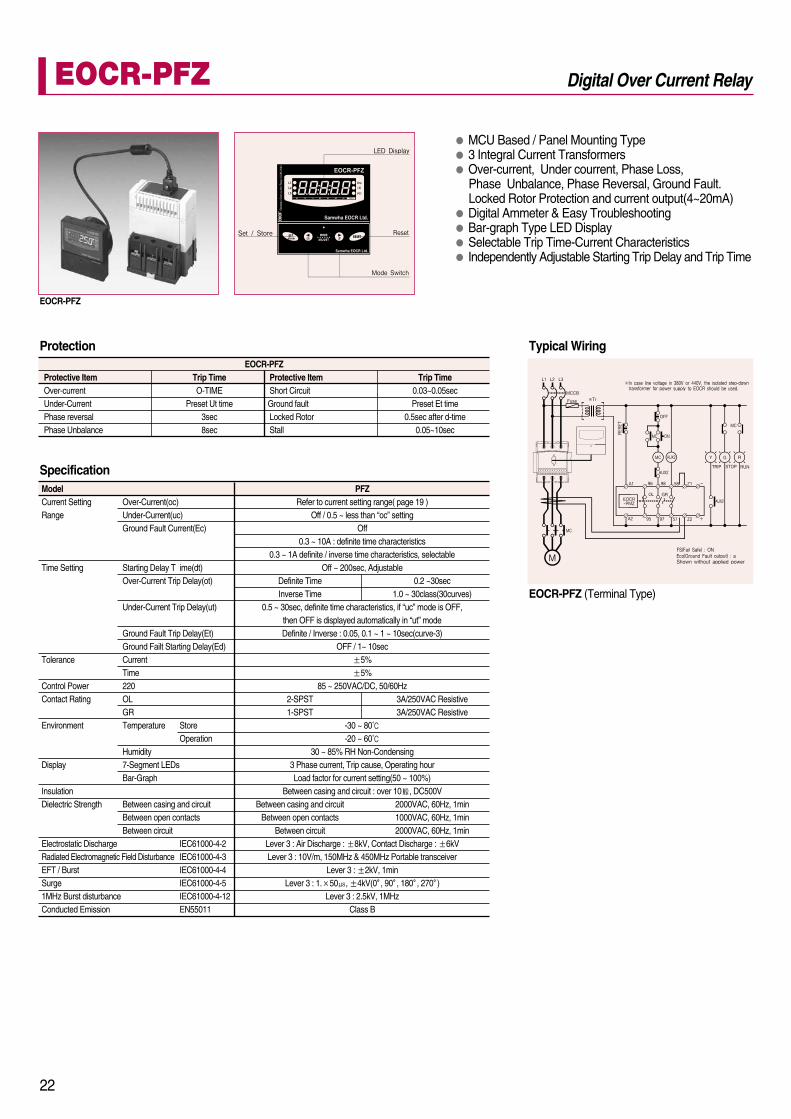
EOCR-PFZProtective Item Trip TimeShort Circuit 0.03~0.05secGround fault Preset Et timeLocked Rotor 0.5sec after d-timeStall 0.05~10sec
Protection
EOCR-PFZ
MCU Based / Panel Mounting Type3 Integral Current TransformersOver-current, Under courrent, Phase Loss, Phase Unbalance, Phase Reversal, Ground Fault. Locked Rotor Protection and current output(4~20mA)Digital Ammeter & Easy TroubleshootingBar-graph Type LED DisplaySelectable Trip Time-Current CharacteristicsIndependently Adjustable Starting Trip Delay and Trip Time
EOCR-PFZ (Terminal Type)
Typical Wiring
22
EOCR-PFZ Digital Over Current Relay
ModelCurrent Setting Over-Current(oc)Range Under-Current(uc)
Ground Fault Current(Ec)
Time Setting Starting Delay T ime(dt)Over-Current Trip Delay(ot)
Under-Current Trip Delay(ut)
Ground Fault Trip Delay(Et)Ground Failt Starting Delay(Ed)
Tolerance CurrentTime
Control Power 220Contact Rating OL
GREnvironment Temperature Store
OperationHumidity
Display 7-Segment LEDsBar-Graph
InsulationDielectric Strength Between casing and circuit
Between open contactsBetween circuit
Electrostatic Discharge IEC61000-4-2Radiated Electromagnetic Field Disturbance IEC61000-4-3EFT / Burst IEC61000-4-4Surge IEC61000-4-51MHz Burst disturbance IEC61000-4-12Conducted Emission EN55011
PFZRefer to current setting range( page 19 )
Off / 0.5 ~ less than “oc” settingOff
0.3 ~ 10A : definite time characteristics0.3 ~ 1A definite / inverse time characteristics, selectable
Off ~ 200sec, AdjustableDefinite Time 0.2 ~30secInverse Time 1.0 ~ 30class(30curves)
0.5 ~ 30sec, definite time characteristics, if “uc” mode is OFF, then OFF is displayed automatically in “ut” modeDefinite / Inverse : 0.05, 0.1 ~ 1 ~ 10sec(curve-3)
OFF / 1~ 10sec5%5%
85 ~ 250VAC/DC, 50/60Hz2-SPST 3A/250VAC Resistive1-SPST 3A/250VAC Resistive
-30 ~ 80-20 ~ 60
30 ~ 85% RH Non-Condensing3 Phase current, Trip cause, Operating hourLoad factor for current setting(50 ~ 100%)
Between casing and circuit : over 10 , DC500VBetween casing and circuit 2000VAC, 60Hz, 1min
Between open contacts 1000VAC, 60Hz, 1minBetween circuit 2000VAC, 60Hz, 1min
Lever 3 : Air Discharge : 8kV, Contact Discharge : 6kVLever 3 : 10V/m, 150MHz & 450MHz Portable transceiver
Lever 3 : 2kV, 1minLever 3 : 1. 50 , 4kV(0 , 90 , 180 , 270 )
Lever 3 : 2.5kV, 1MHzClass B
Specification

FeaturesMCU (Microprocessor Control Unit) BasedDC Motor / DC Device ProtectionSensing by Shunt (DOCR-S) / by Hall Sensor (DOCR-H)Actual primary current is displayed after Shunt/ Hall Sensor setting. (Indication)Digital Setting / Tripped Current digital DATA displayed. (Indication)Auto Reset / Reset Time SettingConfirm Setting Current / Test FunctionNo Volt Release function (Fail-safe Operation) Setting ( NVR Setting)
FeaturesDC Overcurrent Relay for DC MotorThe milli-volt( ) signals generated from the Shunt and power supply are sensed by solid state circuitry and compared with preset overload setting.In case sensing overload condition, the internal relay switches contactafter the preset delay. It has easier control operation.It has DC Overload and DC Underload protection relays. It has wide DC current protection range from 1A to hundreds Amps. DC Ammeter maybe used instead of Shunt(DC Ammeter has its own shunt inside and keep 50mV maintained.)
Typical WiringTypical Wiring
Setting Range(DCL) Setting Range(DUCR)DC Over-current Relay DC Under-current RelaySecondary Voltage of Shunt (10~70m VCD)30sec(Adjustable)Manual(Instantaneous) / Electrical(Remote)Auto(Instantaneous) Reset(Option)LED110 / 220VAC380 / 440VAC
50 / 60HzNormally Energized
Normally De-energizedPanel
Setting Range Setting Range(DOCR/DUCR-S) (DOCR/DUCR-H)0.1 ~ 240A 5 ~ 360A0.5 ~ 25sec 0.5 ~ 25sec0.5 ~ 25sec 0.5 ~ 25sec1A, 2A, 5A, 10A, 20A,50A, 110A, 200A
- 50A, 100A, 200A, 300A24VAC/DC 24VAC/DC85 - 250VAC/DC 85 - 250VAC/DC
50/60HzManual / Electrical / Auto Reset
1-SPDT(1C)3A/ 250VAC Resistive
7Segment LEDPanel
Other Voltage(Option)
Current Setting Type
70Trip Time Setting O-TIMEReset M
AIndicationPower Supply Voltage 220
440Frequency
Contact Rating NR
Mounting
Current Setting
O-TIMEReset TimeRated Shunt
Rated Hall SensorPower Supply Voltage 24
220Frequency
ResetContact Rating Mode
RatingIndicationMounting
Specification Specification
Protective ItemOver-current
In case the line voltage is same voltage with control voltage of DOCR-S type,Contact our representative or our head office.
Trip TimeO-TIME(Definite)
Protection
Protective Item
Over-currentUndercurrent (Dry-run)
Trip Time
DCLO-TIME
-
DUCR-
O-TIME
Protection
23
EOCR-S EOCR-H
Electronic DC CurrentDCL/DUCR Electronic DC CurrentDOCR-S/H

Current Setting Type053060100 - 600
Trip Time Setting O-TIMEResetTime-current Characteristics Power Supply Voltage 24
110220
FrequencyContact Rating Mode
RatingStatus
Mounting
FeaturesCompact DesignThree Integral Current TransformersUnder-load Protection / Dry-run ProtectorWide Current Adjustment RangeDefinite Trip Time CharacteristicManual (instantaneous) / Electrical (Remote) ResetAmbient InsensitiveFail-safe Operation
FeaturesCompact DesignTwo Integral Current TransformersUnder-load Protection (Dry-run Protector)Wide Current Adjustment RangeDefinite Trip Time CharacteristicManual (instantaneous) / Electrical (Remote) ResetAmbient InsensitiveNon-fail-safe Operation
Typical WiringTypical Wiring
Setting Range0.5 - 6A 3.0 - 30A 5.0 - 60A 05 Type fitted to External CT(Current Ratio: 100/5A - 600/5A)0.2 - 30 secManual (Instantaneous) / Electrical (Remote) Definite24VAC/DC110VAC220VAC50/60Hz1-SPDT (1C)3A/250VAC Resistive Normally De-energized35mm DIN-rail / Panel
Current Setting Type053060100 - 600
Trip Time Setting O-TIMEResetTime-current Characteristics Power Supply Voltage 24
110220
FrequencyContact Rating Mode
RatingStatus
Mounting
SpecificationSetting Range0.5 - 6A 3.0 - 30A 5.0 - 60A 05 Type fitted to External CT(Current Ratio: 100/5A - 600/5A)0.2 - 30 secManual (Instantaneous) / Electrical (Remote) Definite24VAC/DC110VAC220VAC50/60Hz2-SPST (1a1b)3A/250VAC Resistive Normally Energized35mm DIN-rail / Panel
Specification
Protective ItemUndercurrent (Dry-run)
Trip TimeO-TIME
ProtectionProtective ItemUndercurrent (Dry-run)
Trip TimeO-TIME
Protection
24
Normally De-energized Normally Energized
Electronic Undercurrent RelayEUCR Electronic Undercurrent RelayEUCR-3C

FeaturesMCU & ASIC Based Compact DesignMultiple Protection FunctionsWide Voltage Adjustment RangeDigital Volt Meter and Digital SettingTrip Cause Display & Easy TroubleshootingManual / Electrical / Automatic ResetAdjustable Reset TimerAmbient Insensitive
EVR - 220 EVR - 380 EVR-415220V 380V 415V
220 - 300V 380 - 460V 415 - 500V160 - 220V 300 - 380V 340 - 415V
0.5 - 2 sec1 - 5 sec
within 0.5 secwithin 0.5 sec (after Supply Power)
Definite1-SPDT(1C), 5A/250VAC Resistive
Manual ResetAutomatic Reset (Reset Time = 5 sec)
Trip in 1 sec (after Pushing TEST Button)Trip Cause is memorized for 24 hours and
Trip Cause will be indicated via LED by pushing Ascertain S/W.
5%15%
Rated Voltage
Voltage Setting OVR-VOLTUVR-VOLT
Trip Time Setting OVR-TIMEUVR-TIME
Phase Loss Trip TimePhase Reversal Trip TimeTime-current CharacteristicContact RatingReset M
ATEST
ASCERTAIN S/W(Trip Cause Indication)
Allowable Tolerance VoltageTime
FeaturesCompact DesignMultiple Protection Functions24 Hours Trip Cause Memory Trip Indication & Troubleshooting Ascertain ButtonManual / Electrical ResetAmbient Insensitive
Typical Wiring
Specification
Typical Wiring
Protective ItemOver-voltageUnder-voltagePhase LossPhase Reversal
Trip TimeOVR-TIMEUVR-TIME
0.5 sec0.5 sec
Protection
Voltage Setting Type110220440
Trip Time Setting O-TIMEU-TIME
Control Voltage 220Others
Contact Rating ModeRatingStatus
Reset SW3=AUTOSW3=MAN
Mounting PDFD DCU
PCU
Over-voltage (O-VOLT) Under-voltage (U-VOLT)110 - 150V 80 - 120V220 - 300V 160 - 240V380 - 500V 300 - 440V
0.5 - 10 sec0.5 - 10 sec
AC/DC85 - 250VAC/DC24, 48V (Optional Order)
1-SPDT(1C)3A/250VAC ResistiveNormally Energized
Reset Time: 1 or 5 sec (DIP-SW4)RESET Button
35mm Din-Rail / PanelFlush
35mm DIN-Rail / Panel
Specification
Protective ItemOver-voltageUnder-voltagePhase LossPhase ReversalVoltage Unbalance
Trip Time (EVR-PD/FD)OVR-TIMEUVR-TIME
2 sec0.1 sec
3 sec
Protection
EVR-FDEVR-PD
25
Electronic AC Voltage RelayEVR Digital AC Voltage RelaysEVR-PD/FD

Protective ItemOver-voltageUndervoltage
Trip TimeO-TIMEO-TIME
DC Over-voltage DC UndervoltageVoltage Setting Range1 ~ 10V -3 ~ 30V 3 ~ 30V10 ~ 110V 20 ~ 110V20 ~ 220V 30 ~ 220VOption0.2 ~ 30secManual(Instantaneous) / Electrical Reset Auto (Option)110/220VAC, 50/60HzOther Voltage Option3A/250VAC ResistiveNormally De-energizedPanel
Setting Range100 ~ 160VDC60 ~ 110VDC0.5 ~ 25sec0.5 ~ 25sec24VAC/DC85 ~ 250VAC/DC50/60HzManual / Electrical / Auto Reset35mm DIN-Rail / Panel
Protective Item
Over-voltageUndervoltage
Trip TimeDOVR DUVRO-TIME -
- O-TIME
ModelVoltage Setting Type
1030110220Others
Trip Time Setting Trip Delay O-TIMEReset M
AControl Voltage 220
OthersContact Rating Mode 1-SPDT(1C)
Status R TypeMounting
ModelOver-voltage OVRUndervoltage UVRTrip Time O-TIMEReset Time R-TIMEPower Supply Voltage 24
220Frequency
ResetMounting
FeaturesMCU (Microprocessor Control Unit) BasedDC Motor / DC Device ProtectionSeparate Setting for Over-voltage and UndervoltageLine Voltage Indicative Function (FND)Digital Setting / Trip Cause IndicationAuto Reset / Reset Time SettingConfirm Setting Value / TEST FunctionNo Volt Release Function (Fail-safe Operation) Setting( NVR Setting)
FeaturesCompact DesignDefinite Trip Time-current CharacteristicTrip & Run Indication (LED)Confirm actual current and precise setting possible as it has Voltage Meter.Solid State DC Over-voltage / Undervoltage Protection.
Typical WiringTypical Wiring
Specification Specification
ProtectionProtection
26
Electronic DC Voltage RelayDOVR/DUVR Electronic DC Voltage RelayDVR

FeaturesMCU Based Compact DesignGround (Earth) Fault Protection for Motor and Power Distribution SystemsZero Phase Current Detection MethodTest Button Provides a Manual Self-testing FunctionIndependently Adjustable Ground (Earth) Current andTrip (Operating) Delay TimeBuilt-in Power Indication LED and Trip Indication LED
Typical WiringTypical Wiring
Earth Leakage RelayELR Ground(Earth) Fault RelayEFR2.5
27
0.03 ~ 3A(0.03, 0.07, 0.1, 0.3, 0.5, 1, 1.5, 2, 2.5 and 3A Tap )0.2 ~ 2.0sec(0.2, 0.4, 0.6, 0.8, 1.0, 1.2, 1.4, 1.6, 1.8 and 2.0 sec Tap)Definite TimeZCT(CBCT) - Zero Phase Current Detection240VAC 10%50/60Hz
5%5%
5A/250VAC Resistive1-SPDT / Normally De-energized600VAC, 50/60Hz10,000,000 Operation100,000 Operation-20 ~ 6010 ~ 85% without CondensationCasing-Circuit 2kV, 50/60Hz, 1minContact-Contact 1kV, 50/60Hz, 1minCircuit-Circuit 2kV, 50/60Hz, 1minIEC61000-4-2 Level-3IEC61000-4-4 Level-3IEC61000-4-5 Level-3IEC61000-4-11Flush Mount (Panel Door Mount)
Current Setting
Time Setting
Operating CharacteristicCurrent SensingControl VoltageFrequencyCurrent ToleranceTime ToleranceContact Rating
Rated Insulation VoltageExpected Mechanical LifeExpected Electrical LifeAmbient TemperatureAmbient HumidityDielectric Strength
Electrostatic DischargeEFT / BurstSurgeVoltage Dip & InterruptionMounting
Specification
FeaturesMCU Based Compact DesignGround (Earth) Fault Protection for Motor and Power Distribution SystemsResidual Current Distribution Method Test Button Provides a Manual Self-testing FunctionIndependently Adjustable Ground (Earth) Current andTrip (Operating) Delay TimeBuilt-in Power Indication LED and Trip Indication LED
0.1 ~ 2.5A(0.1, 0.3, 0.5, 0.7, 1.0 , 1.3, 1.5, 1.7, 2.0 and 2.5A Tap)0.2 ~ 2.0sec(0.2, 0.4, 0.6, 0.8, 1.0, 1.2, 1.4, 1.6, 1.8 and 2.0 sec Tap)Definite TimeResidual Current Detection240VAC 10%50/60Hz
5%5%
5A/250VAC Resistive1-SPDT / Normally De-energized600VAC, 50/60Hz10,000,000 Operation100,000 Operation-20 ~ 6010 ~ 85% without CondensationCasing-Circuit 2kV, 50/60Hz, 1minContact-Contact 1kV, 50/60Hz, 1minCircuit-Circuit 2kV, 50/60Hz, 1minIEC61000-4-2 Level-3IEC61000-4-4 Level-3IEC61000-4-5 Level-3IEC61000-4-11Flush Mount (Panel Door Mount)
Current Setting
Time Setting
Operating CharacteristicCurrent SensingControl VoltageFrequencyCurrent ToleranceTime ToleranceContact Rating
Rated Insulation VoltageExpected Mechanical LifeExpected Electrical LifeAmbient TemperatureAmbient HumidityDielectric Strength
Electrostatic DischargeEFT / BurstSurgeVoltage Dip & InterruptionMounting
Specification

Range3 160 - 300VAC, 50/60Hz3 340 - 480VAC, 50/60Hz
Manual (Instantaneous) / Electrical Automatically reset with 5 sec delay
when supply power comes to normal.1 - SPDT (1C)
5A/250VAC ResistiveNormally Energized35mm DIN-rail/Rail
Control Voltage Type220440
Reset
Contact Rating ModeRatingStatus
Mounting
FeaturesMCU Based Compact DesignMultiple Protection Functions2 - 15% Voltage Unbalance SettingTrip Cause Indication & TroubleshootingManual / Electrical / Automatic ResetAmbient InsensitiveFail-safe Operation
Specification
Typical Wiring
Protective ItemPhase ReversalPhase LossVoltage Unbalance
Trip Time0.1 sec1 sec 5 sec
Protection
Troubleshooting
Condition
Normal RunVoltage Unbalancing
Green LED Red LEDLED Signal (Pulse Chart)
OnOnOffOffOffOff
OffOnOn
FlickeringFlickeringFlickering
Flickering alternatively
Voltage Unbalance
TripPhaseLoss
Phase Reversal
RST
Electronic Phase Monitoring RelayPMR
28
Typical Wiring
Range50 - 500mA100 - 1,000mA200 - 2,500mA0.2 - 2.0 secManual / Electrical(Push RESET Button or Interrupt Supply Power)110 / 220VAC, 50/60Hz1-SPDT(1C), 3A/250VAC ResistiveNormally De-energized35mm DIN-Rail / Panel
Ground Fault (GF) TypeCurrent Setting 05
1020
Trip Time Setting O-TIMEReset
Power SuppyContact Rating Mode/Rating
StatusMounting
FeaturesMCU Based Compact DesignGround Fault Protection with ZCTTrip & Run Indication LEDManual / Electrical Reset
Specification
Protective ItemGround Fault
Trip TimeO-Time
Protection
Electronic Ground Fault RelayEGR

29
ModelCurrent RatioClassBuddenInsulation VoltageDielectric StrengthInsulationMounting
Current Ratio
Tolerance (Protection Class)BuddenSecondary CurrentInsulation VoltageDielectric StrengthInsulationMounting
Current Ratio (SR-CT)100 : 5A150 : 5A200 : 5A300 : 5A400 : 5A
3%(10P10 / IF=10)1.25VA (5VA: Measuring Class)
5A600VAC
3kV10M (500VDC Megger)35mm DIN-Rail / Panel
Specification
Specification
FeaturesFitted to EOCR relays for Large Amp Motor Protection 1.0 Measuring Class For EOCR Only
FeaturesFitted to EOCR relays for Large Amp Motor Protection Satisfied with IEC Inverse Trip CharacteristicProtection Class For EOCR Only
2CT-100100 : 5A
1.05VA
2CT-150150 : 5A
1.05VA
600VAC2kV
10M (500VDC Megger)Panel
2CT-200200 : 5A
1.05VA
2CT-300300 : 5A
1.05VA
2CT-400400 : 5A
1.05VA
TypeSR-CT-100SR-CT-150SR-CT-200SR-CT-300SR-CT-400
ModelCurrent RatioClassBuddenInsulation VoltageDielectric StrengthInsulationMounting
Specification3CT-100100 : 5A
1.05VA
3CT-150150 : 5A
1.05VA
600VAC2kV
10M (500VDC Megger)Panel
3CT-200200 : 5A
1.05VA
3CT-300300 : 5A
1.05VA
3CT-400400 : 5A
1.05VA
FeaturesFitted to EOCR relays for Large Amp Motor Protection 1.0 Measuring ClassFor EOCR Only
Hole Dimension
Primary GF CurrentSecondary GF CurrentToleranceBuddenRated VoltageDielectric StrengthInsulationMounting
TypeZCT - 35ZCT - 80ZCT - 120
Hole35mm80mm120mm200mA1.5mA
10%10VA
600VAC2kV
10M (500VAC Megger)Panel
FeaturesApplicable for Ground Fault Protection Devices (EGR)Detect Zero Phase CurrentFor EOCR Only
Specification
Zero Phase Current TransformerZCT
Current Transformer2CT Current Transformer3CT
Current TransformerSR-CT

EOCR-SS / AR / EUCR
EOCR-SS1 / SS2
EOCR-SP / SP1 / SP2-01 / 10Type
EOCR-SP / SP1 / SP2-20Type
SDDR
EOCR-DS / DS1 / DS2 / DS3
EOCR-DST / DS1T / DS2T / DS3T
PMR / EVR / EVR-PD
EOCR-3DD(E) / 3DZ(E) / EUCR-3C / 3DM / 3MS / 3MZ
EOCR-PMZ
Dimension
30

31
EVR-FD
ELR / EFR2.5
EOCR-PFZ
DCL / DCUR / DOVR / DUVR
ECOR-S,H / DVR / EGR
2CT
3CT
SR-CT

EOCR-FD(E) / FDZ(E) / FDM / FMS / FDZ ZCT
32
Dimension

MEMO

MEMO

MEMO

Head Office6th floor, Cheil Bldg., 94-46, Youngdeungpo-Dong 7Ka, Youngdeungpo-Ku, Seoul, KoreaTel. 82 2 3473 2340 / Fax 82 2 3473 1159Iksan Plant574, Yongie-dong, Iksan-shi, Junbuk, KoreaTel. 82 63 835 5033 / Fax 82 63 835 4175
April 07
EOC
R_E
N20
07 S
amw
ha E
OC
R L
td.-A
ll rig
hts
rese
rved
.


