

1 1
EMQ Series
EMQ Series Rotary Cylinder
EMQ Series
Series No Bore - Magnet No - Cushion Type - Thread Type
EMQ 10203050
S: With magnet( Magnet is standard)
A: With adjustment boltR: With shock absorber
Blank G:P :PTT :NPT
Order Example:EMQ Series Rotary Cylinder, Bore 30, with adjustment bolt, G Thread, ERP code is: EMQ30-S-A
Note: Specific Bore and Stroke of the cylinder subject to the drawing.
Allowable Kinetic Energy and Rotation Time Adjustment Range
EMQ10
EMQ20
EMQ30
EMQ50
ModelAllowable kinetic energy (J) Rotation time adjustment range for stable operation (s/90°)
With adjutment bolt
0.01
0.025
0.05
0.08
0.04
0.12
0.12
0.30
0.2~1.0
0.2~1.0
0.2~1.0
0.2~1.0
0.2~0.7
0.2~0.7
0.2~0.7
0.2~0.7
Note 1. If operated where the kinetic energy exceeds the allowable value, this may cause damage to theinternal parts and result in product failure. Please pay special attention to the kinetic energylevels when designing and during operation to avoid exceeding the allowable limit.
2. When the rotation time of the type with an internal absorber is set longer than the time shown inthe table above, energy absorption of the shock absorber greatly decreases.
0
2
4
6
8
10
0.2 0.4 0.6 0.8 1.0
Eff
ect
ive
to
rqu
eN
.m(
)
EMQ10
EMQ20
EMQ30
EMQ50
Working pressure MPa( )
Effective Output Torgue
EMQ Series Rotary Cylinder
1.Rotation direction and rotation angle
1.1 When the pressurized from port A ,the shaft rotates clockwise and to anticlockwise when pressurized from port B .
1.2 To obtain the desired rotation angle ,the rotation ends can be set within the range shown in the diagram byregulating the adjustment bolt.
1.3 Rotary table with shock absorber is available to adjust rotation angle.
Note:* The figure shows rotation range of positioning pinhole
* Position of pinhole in the figure shows anticlockwiserotation when the roattion angle is set at 180°by equallytightening the adjusting bolts A and B .
* Adjustment bolt or shock absorber at maximumoutward is factory setting, please adjust inward for firstuse if necessary.
Clockwise rota�on
end adjustment range 95°
An�
cloc
kwis
e ro
ta�
on
end
adju
stm
ent r
ange
95°
Max. Rota�on range 190°
Posi�oning pinholeAn�clockwise
clockwise
An�clockwise
Adjustment bolt A
(For adjus�ng an�clockwise end)
Adjustment bolt B
(For adjus�ng clockwise end)
With shcok absorber With adjutment bolt With shcok absorber
Product Features
1.Rack and pinion structure, stable operation.2.Small rotary tolerance, good dynamic.3.Double cylinder can achieve double power.4.Rack and pinion made of special materials & heat treatment.5.High precision processed, accurate positioning .6.Accommodates wiring and pipingfor equipment mounted on the table from hollow axis.7.Mounting from 2 directions.8.Adjustment bolt and shock absorber are optional.
Installation and Use
1.40
1 1
Weight g( )530
5 04
1020
1020
1310
1310
2130
2140
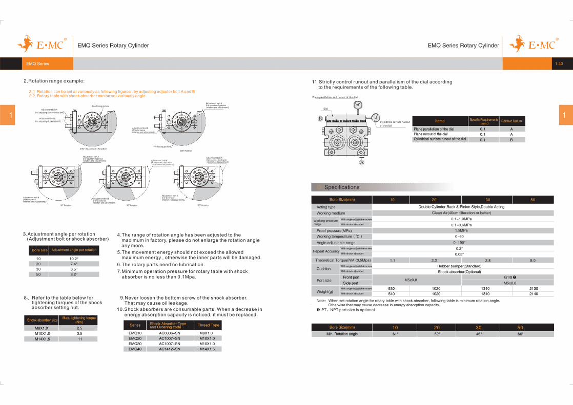
Note:When set rotation angle for rotary table with shock absorber, following table is minimum rotation angle.Otherwise that may cause decrease in energy absorption capacity.
Specifications
2010 30 50
Acting type
Working medium
Working pressurerange
Proof pressure(MPa)
Repeat Accuracy
Cushion
Bore Size(mm)
Double Cylinder,Rack & Pinion Style,Double Acting
Clean Air(40um filteration or better)
Port size M5x0.8G1 8/ 1
Theoretical Torque(NM)(0.5Mpa)
With angle adjustable screw
Front port
Side port
0~190°
0.2°
0~60
0 05. °
Angle adjustable range
Working temperature(℃)
1.1 2 2. 2 8. 5 0.
Rubber bumper(Standard)
Shock absorber(Optional)
M5x0.8
With shock absorber
With angle adjustable screw
With shock absorber
With angle adjustable screw
With shock absorber
1 PT NPT port size is optional、
0.1~ .1 0MPa
1.5MPa
0.1~ .0 6MPa
With angle adjustable screw
With shock absorber
EMQ Series
EMQ Series Rotary Cylinder EMQ Series Rotary Cylinder
Bore size Adjustment angle per rotation
10
20
30
50
10.2°
7 4. °
6 5. °
8 2. °
3.Adjustment angle per rotation(Adjustment bolt or shock absorber)
8、Refer to the table below fortightening torques of the shockabsorber setting nut.
M8X1.0
M14X1.5
Shcok absorber size
M10X1.0
2.5
3.5
11
4.The range of rotation angle has been adjusted to themaximum in factory, please do not enlarge the rotation angleany more.
5.The movement energy should not exceed the allowedmaximum energy , otherwise the inner parts will be damaged.
6.The rotary parts need no lubrication.
7.Minimum operation pressure for rotary table with shockabsorber is no less than 0.1Mpa.
Max. tightening torque(Nm)
EMQ10
EMQ20
EMQ30
EMQ40
Series Shcok Absorber Typeand Ordering code Thread Type
AC0806-SN
AC1007-SN
AC1007-SN
AC1412-SN
M8X1.0
M10X1.0
M10X1.0
M14X1.5
9.Never loosen the bottom screw of the shock absorber.That may cause oil leakage.
10.Shock absorbers are consumable parts. When a decrease inenergy absorption capacity is noticed, it must be replaced.
11.Strictly control runout and parallelism of the dial accordingto the requirements of the following table.
B
A
�
���� ����
�������Plane parallelism of the dialPlane runout of the dialCylindrical surface runout of the dial
Items Relative Datum
0.1
0.1
0.1
Specific Requirements( )mm
A
A
B
Dial
Plane parallelism and runout of the dial
Cylindrical surface runout
of the dial
2.Rotation range example:
2.1 Rotation can be set at variously as following figures , by adjusting adjuster bolt A and B2.2 Rotary table with shock absorber can be set variously angle.
Adjustment bolt A
(For adjus�ng an�clockwise end)
Adjustment bolt B
(For adjus�ng clockwise end)
Posi�oning pinhole
190° (Maximum) Rota�on
Adjustment bolt A(For counter-clockwiserota�on end adjustment)
Adjustment bolt B(For clockwiserota�on end adjustment)
Posi�oning pin hole
Adjustment bolt A(For counter-clockwiserota�on end adjustment) Adjustment bolt A
(For counter-clockwiserota�on end adjustment)
Adjustment bolt A(For counter-clockwiserota�on end adjustment)
Adjustment bolt B(For clockwiserota�on end adjustment)
Adjustment bolt B(For clockwiserota�on end adjustment)
Adjustment bolt B(For clockwiserota�on end adjustment)
90° Rota�on 90° Rota�on 90° Rota�on
180° Rota�on
10 20 30 50Min. Rotation angle
Bore Size(mm)
1 1
EMQ series
Way
2-JThroughJA Depth of counter bore JB
4-JJ Depth 8
8-WD Depth WWCircumference 8 equivalents: XB
DepthXC
WB
Depth
WC
10.518
8.514
8.514
6.511
10.3
8.6
8.6
6.8
20
17
17
13
7.5
6.5
6.5
4.5
3.5
3.5
3
3.5
5.5
5
6.5
4.5
12
10
10
8
26+0.0520
22+0.0520
17+0.0430
11
10
9
5
35+0.0620
32+0.0620
28+0.0520
770-0.074
670
-0.074
610
-0.074
750
-0.074
650
-0.074
600
-0.074
450-0.062
37.5
33.5
30
28
10
7
5
6.5
50
37
34
27
100
84
76
60
37.5
32
30
63
50
47
15.5
12
12
9.5
6
5
5
4
22
18.5
16
38
29
27.5
20
70
80
65
85
75
70.4
55.4 50 2815.5 34.5
M12X1.75
M10X1.5
M10X1.5
M8X1.25
Model
10
20
30
50
AA A AV AW AY BA BB BC BD BE CA CB D DD DE DF DG FA FB FC FD H J JA JB JC20
+0.052046
0-0.062
15+0.0430
10
20
30
50
WFWDWCWAUUSUSFSESDSQPJUJJJD WB WE XA XB XC YA YB YC
15471399234M5X0.812 M5X0.8 45M8X1 17.3
20.55459.7121011737M6X115 M5X0.8M10X1 24.8
235764.71411.512740M6X115 1/8"M10X1 24.8
26.56674.71514.515246M8X1.2518 1/8"M14X1.5 31.3 5+0.030
4+0.030
4+0.030
3+0.0250
45
39
36
27
55
48
43
32
12
10
10
8
M6X1
M8X1.25
M6X1
M5X0.8
5.5
4.5
4.5
3.5
5 +0.030
4+0.030
4+0.030
3+0.0250
5.5
4.54.5
3.5
5 +0.030
4 +0.030
4 +0.030
3+0.0250
33
2824
19
5.5
4.54.5
3.5
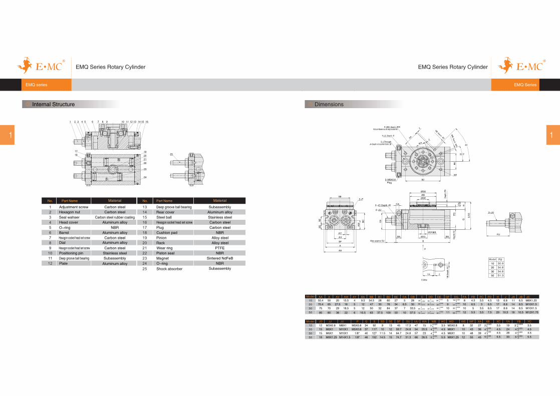
Dimensions
Model
30 9.
.34 8
.34 8
.51 3
Model
EMQ Series Rotary Cylinder
Internal Structure
17
18
No. Part Name Material
1
2
3
4
5
6
7
8
9
10
11
12
13
14
15
16
17
18
19
20
21
22
23
24
Adjustment screw
Hexagon nut
Seal wahser
Head cover
O-ring
Barrel
Hexagon socket head set screwDial
Hexagon socket head set screw
Positioning pin
Deep groove ball bearing
Plate
Carbon steel
Carbon steel
Carbon steel rubber coating
Aluminum alloy
NBR
Aluminum alloy
Carbon steelAluminum alloy
Carbon steel
Stainless steel
Subassembly
Deep groove ball bearing Subassembly
25
Rear cover Aluminum alloy
Steel ball Stainless steel
Hexagon socket head set screw Carbon steel
Plug Carbon steel
Cushion pad NBR
Pinion
Rack Alloy steel
Alloy steel
PTFEWear ring
NBRPiston seal
Sintered NdFeBMagnet
NBRO-ring
Shock absorber
No. Part Name Material
Aluminum alloySubassembly
EMQ Series
EMQ Series Rotary Cylinder


