

Machine Automation Control ler NJ-series
General-purpose Seriarl Connection Guide (RS-232C) OMRON Corporation
G9SP Safety Controller
P545-E1-01

About Intellectual Property Rights and Trademarks
Microsoft product screen shots reprinted with permission from Microsoft Corporation. Windows is a registered trademark of Microsoft Corporation in the USA and other countries.
EtherCAT® is registered trademark and patented technology, licensed by Beckhoff Automation
GmbH, Germany.
Sysmac is a trademark or registered trademark of OMRON Corporation in Japan and other
countries for OMRON factory automation products.
Company names and product names in this document are the trademarks or registered
trademarks of their respective companies.

Table of Contents
1. Related Manuals ........................................................................................ 1 2. Terms and Definitions ............................................................................... 1 3. Remarks ..................................................................................................... 2 4. Overview .................................................................................................... 3 5. Applicable Products and Support Software............................................ 4
5.1. Applicable Products ........................................................................... 4 5.2. Device Configuration.......................................................................... 5
6. Serial Communications Settings ............................................................. 6 6.1. Serial Communications Settings ........................................................ 6 6.2. Cable Wiring Diagram........................................................................ 7 6.3. Example of Checking Connection ...................................................... 8
7. Connection Procedure .............................................................................. 9 7.1. Work Flow .......................................................................................... 9 7.2. Setting Up the Safety Controller....................................................... 10 7.3. Setting Up the Controller...................................................................11 7.4. Connection Status Check................................................................. 22
8. Initialization Method................................................................................ 24 8.1. Initializing the Controller................................................................... 24
9. Project File ............................................................................................... 26 9.1. Overview .......................................................................................... 26 9.2. Destination Device Command.......................................................... 29 9.3. Error Detection Processing .............................................................. 33 9.4. Variables .......................................................................................... 34 9.5. Ladder Program ............................................................................... 37 9.6. Timing Charts................................................................................... 49 9.7. Error Status List ............................................................................... 51
10. Revision History ...................................................................................... 54
1. Related Manuals
1
1. Related Manuals
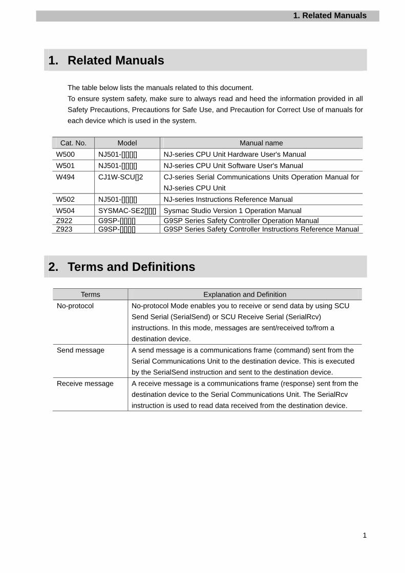
The table below lists the manuals related to this document.
To ensure system safety, make sure to always read and heed the information provided in all
Safety Precautions, Precautions for Safe Use, and Precaution for Correct Use of manuals for
each device which is used in the system.
Cat. No. Model Manual name
W500 NJ501-[][][][] NJ-series CPU Unit Hardware User's Manual
W501 NJ501-[][][][] NJ-series CPU Unit Software User's Manual
W494 CJ1W-SCU[]2 CJ-series Serial Communications Units Operation Manual for
NJ-series CPU Unit
W502 NJ501-[][][][] NJ-series Instructions Reference Manual
W504 SYSMAC-SE2[][][] Sysmac Studio Version 1 Operation Manual Z922 G9SP-[][][][] G9SP Series Safety Controller Operation Manual Z923 G9SP-[][][][] G9SP Series Safety Controller Instructions Reference Manual
2. Terms and Definitions
Terms Explanation and Definition
No-protocol No-protocol Mode enables you to receive or send data by using SCU
Send Serial (SerialSend) or SCU Receive Serial (SerialRcv)
instructions. In this mode, messages are sent/received to/from a
destination device.
Send message A send message is a communications frame (command) sent from the
Serial Communications Unit to the destination device. This is executed
by the SerialSend instruction and sent to the destination device.
Receive message A receive message is a communications frame (response) sent from the
destination device to the Serial Communications Unit. The SerialRcv
instruction is used to read data received from the destination device.

3. Remarks
2
3. Remarks
(1) Understand the specifications of devices which are used in the system. Allow some
margin for ratings and performance. Provide safety measures, such as installing safety
circuit in order to ensure safety and minimize risks of abnormal occurrence.
(2) To ensure system safety, always read and heed the information provided in all Safety
Precautions, Precautions for Safe Use, and Precaution for Correct Use of manuals for
each device used in the system.
(3) The user is encouraged to confirm the standards and regulations that the system must
conform to.
(4) It is prohibited to copy, to reproduce, and to distribute a part of or whole part of this
document without the permission of OMRON Corporation.
(5) The information contained in this document is current as of August 2013. It is subject to
change without notice for improvement.
The following notation is used in this document.
Indicates a potentially hazardous situation which, if not avoided, will result in minor or moderate injury, or may result in serious injury or death. Additionally there may be significant property damage.
Indicates a potentially hazardous situation which, if not avoided, may result in minor or moderate injury or in property damage.
Precautions for Safe Use
Precautions on what to do and what not to do to ensure safe usage of the product.
Precautions for Correct Use
Precautions on what to do and what not to do to ensure proper operation and performance.
Additional Information Additional information to read as required.
This information is provided to increase understanding or make operation easier.
4. Overview
3
4. Overview
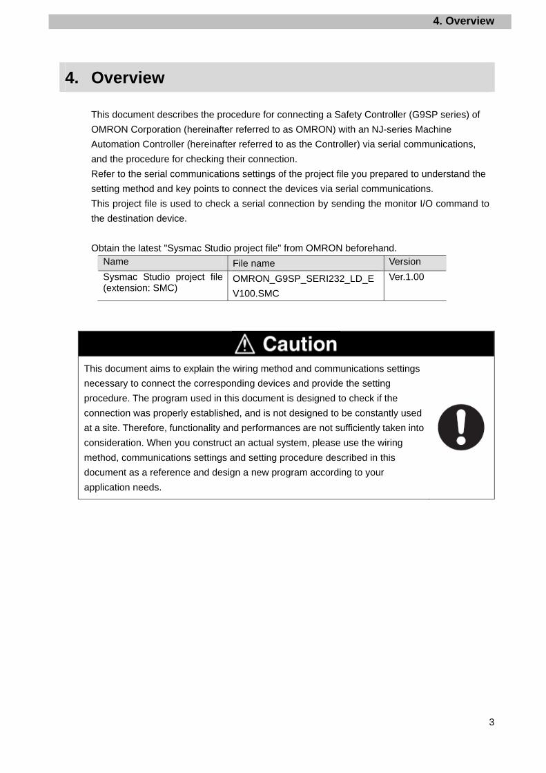
This document describes the procedure for connecting a Safety Controller (G9SP series) of
OMRON Corporation (hereinafter referred to as OMRON) with an NJ-series Machine
Automation Controller (hereinafter referred to as the Controller) via serial communications,
and the procedure for checking their connection.
Refer to the serial communications settings of the project file you prepared to understand the
setting method and key points to connect the devices via serial communications.
This project file is used to check a serial connection by sending the monitor I/O command to
the destination device.
Obtain the latest "Sysmac Studio project file" from OMRON beforehand. Name File name Version
Sysmac Studio project file (extension: SMC)
OMRON_G9SP_SERI232_LD_E
V100.SMC
Ver.1.00
This document aims to explain the wiring method and communications settings
necessary to connect the corresponding devices and provide the setting
procedure. The program used in this document is designed to check if the
connection was properly established, and is not designed to be constantly used
at a site. Therefore, functionality and performances are not sufficiently taken into
consideration. When you construct an actual system, please use the wiring
method, communications settings and setting procedure described in this
document as a reference and design a new program according to your
application needs.
5. Applicable Products and Support Software
4
5. Applicable Products and Support Software
5.1. Applicable Products
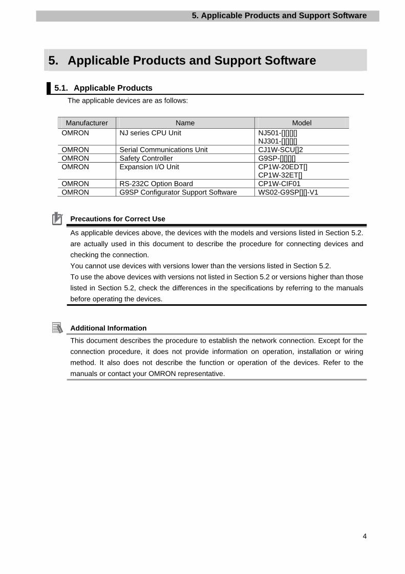
The applicable devices are as follows:
Manufacturer Name Model OMRON NJ series CPU Unit NJ501-[][][][]
NJ301-[][][][] OMRON Serial Communications Unit CJ1W-SCU[]2 OMRON Safety Controller G9SP-[][][][] OMRON Expansion I/O Unit CP1W-20EDT[]
CP1W-32ET[] OMRON RS-232C Option Board CP1W-CIF01 OMRON G9SP Configurator Support Software WS02-G9SP[][]-V1
Precautions for Correct Use
As applicable devices above, the devices with the models and versions listed in Section 5.2.
are actually used in this document to describe the procedure for connecting devices and
checking the connection.
You cannot use devices with versions lower than the versions listed in Section 5.2.
To use the above devices with versions not listed in Section 5.2 or versions higher than those
listed in Section 5.2, check the differences in the specifications by referring to the manuals
before operating the devices.
Additional Information This document describes the procedure to establish the network connection. Except for the
connection procedure, it does not provide information on operation, installation or wiring
method. It also does not describe the function or operation of the devices. Refer to the
manuals or contact your OMRON representative.
5. Applicable Products and Support Software
5
5.2. Device Configuration
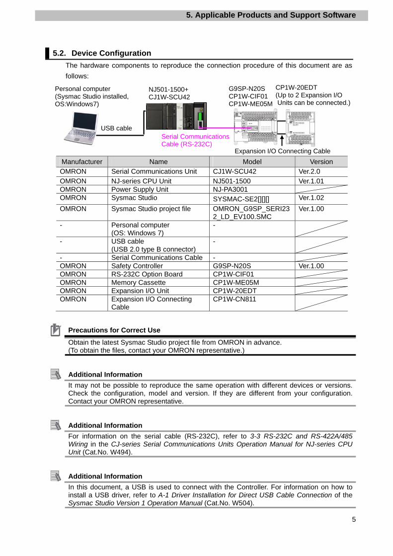
The hardware components to reproduce the connection procedure of this document are as
follows:
4
Manufacturer Name Model Version OMRON Serial Communications Unit CJ1W-SCU42 Ver.2.0 OMRON NJ-series CPU Unit NJ501-1500 Ver.1.01 OMRON Power Supply Unit NJ-PA3001 OMRON Sysmac Studio SYSMAC-SE2[][][] Ver.1.02
OMRON Sysmac Studio project file OMRON_G9SP_SERI232_LD_EV100.SMC
Ver.1.00
- Personal computer (OS: Windows 7)
-
- USB cable (USB 2.0 type B connector)
-
- Serial Communications Cable - OMRON Safety Controller G9SP-N20S Ver.1.00 OMRON RS-232C Option Board CP1W-CIF01 OMRON Memory Cassette CP1W-ME05M OMRON Expansion I/O Unit CP1W-20EDT OMRON Expansion I/O Connecting
Cable CP1W-CN811
Precautions for Correct Use Obtain the latest Sysmac Studio project file from OMRON in advance. (To obtain the files, contact your OMRON representative.)
Additional Information It may not be possible to reproduce the same operation with different devices or versions. Check the configuration, model and version. If they are different from your configuration. Contact your OMRON representative.
Additional Information For information on the serial cable (RS-232C), refer to 3-3 RS-232C and RS-422A/485 Wiring in the CJ-series Serial Communications Units Operation Manual for NJ-series CPU Unit (Cat.No. W494).
Additional Information In this document, a USB is used to connect with the Controller. For information on how to install a USB driver, refer to A-1 Driver Installation for Direct USB Cable Connection of the Sysmac Studio Version 1 Operation Manual (Cat.No. W504).
NJ501-1500+ CJ1W-SCU42
Personal computer (Sysmac Studio installed, OS:Windows7)
USB cable Serial Communications Cable (RS-232C)
G9SP-N20S CP1W-CIF01 CP1W-ME05M
CP1W-20EDT (Up to 2 Expansion I/O Units can be connected.)
Expansion I/O Connecting Cable

6. Serial Communications Settings
6
6. Serial Communications Settings
This section describes the specifications such as cable wiring and communication parameters
that are set in this document.
Additional Information This document and project file can be used to perform operations using the settings and
command described in this section. Modifications are necessary to perform communications
using different settings.
6.1. Serial Communications Settings
The table below lists the settings for serial communications.
CJ1W-SCU42 G9SP-N20S
Unit number 0 -
Communications (connection) port Port 2 (RS-232C) -
Serial communications mode No-protocol -
Data length 8 bits 8 bits (fixed)
Stop bit 1 bit 1 bit (fixed)
Parity Even (default value) Even (fixed)
Baud rate 9,600 bps (default value) 9,600 bps (fixed)
No-protocol Start Code Yes (#40) #40 (fixed)
No-protocol End Code No (#2A0D (fixed))
*One byte data can only be set as the no-protocol End Code. Thus, in this document, #2A0D
is treated as data.
Precautions for Correct Use
This document explains the setting procedure with Serial Communication Unit CJ1W-SCU42
whose Unit No. is 0, communication port is port 2 and device name is SCU. To connect
devices under different conditions, refer to 9. Project File and create a ladder program by
changing the variable names and setting values.

6. Serial Communications Settings
7
6.2. Cable Wiring Diagram
For details on the cable wiring, refer to Section 3 Installation and Wiring in the CJ-series Serial
Communications Units Operation Manual for NJ-series CPU Unit (Cat.No. W494).
Check the connector configuration and pin assignment before wiring.
■Connector configuration and pin assignment < OMRON G9SP-N20S + CP1W-CIF01 > Applicable Connectors: D-sub 9 pin
<OMRON CJ1W-SCU42> Applicable connector: D-sub 9 pin
■Cable/pin assignment CJ1W-SCU42 Serial Communications Unit
Safety Controller (G9SP-N20S)
Signal
name
Pin No. Pin No. Signal
name
FG 1 1 FG
SD 2 2 SD
RD 3 3 RD
RS 4 4 RS
CS 5 5 CS
5V 6 6 5V
DR 7 7 DR
ER 8 8 ER
SG 9 9 SG
RS-232C
Interface
FG Shell Shell FG
RS-232C
Interface
D-sub 9-pin Cable connector type: Male
D-sub 9-pin Cable connector type: Male
6. Serial Communications Settings
8
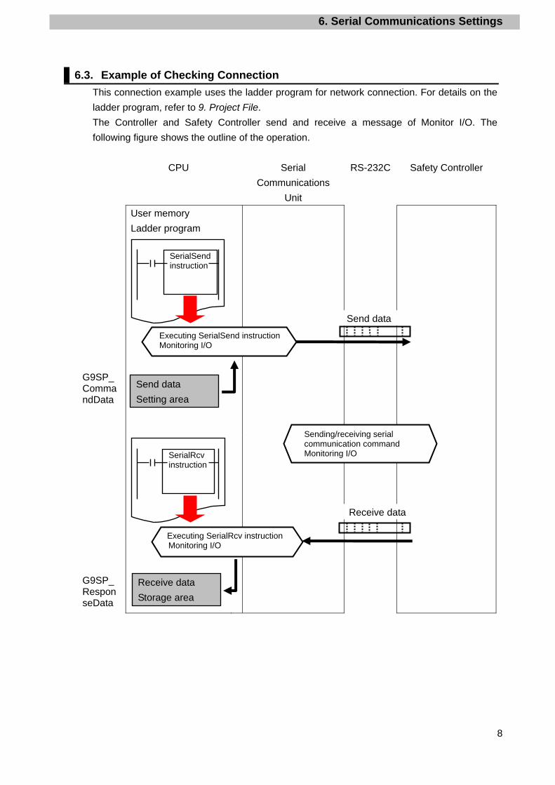
6.3. Example of Checking Connection
This connection example uses the ladder program for network connection. For details on the
ladder program, refer to 9. Project File.
The Controller and Safety Controller send and receive a message of Monitor I/O. The
following figure shows the outline of the operation.
CPU Serial
Communications
Unit
RS-232C Safety Controller
User memory
Ladder program
G9SP_CommandData
G9SP_ResponseData
SerialRcv instruction
SerialSend instruction
Send data
Receive data
Receive data
Storage area
Send data
Setting area
Executing SerialSend instructionMonitoring I/O
Sending/receiving serial communication command Monitoring I/O
Executing SerialRcv instructionMonitoring I/O
7. Connection Procedure
9
7. Connection Procedure
This section describes the procedure for connecting the Controller via serial communications.
This document explains the procedures for setting up the Controller from the factory default
setting. For the initialization, refer to Section 8 Initialization Method.
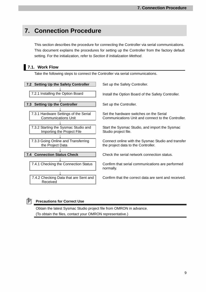
7.1. Work Flow
Take the following steps to connect the Controller via serial communications.
7.2 Setting Up the Safety Controller Set up the Safety Controller. ↓
7.2.1 Installing the Option Board Install the Option Board of the Safety Controller.
↓ 7.3 Setting Up the Controller Set up the Controller.
↓ 7.3.1 Hardware Settings of the Serial
Communications Unit Set the hardware switches on the Serial Communications Unit and connect to the Controller.
↓ 7.3.2 Starting the Sysmac Studio and
Importing the Project File Start the Sysmac Studio, and import the Sysmac Studio project file.
↓ 7.3.3 Going Online and Transferring
the Project Data Connect online with the Sysmac Studio and transfer the project data to the Controller.
↓ 7.4 Connection Status Check Check the serial network connection status.
↓ 7.4.1 Checking the Connection Status Confirm that serial communications are performed
normally. ↓
7.4.2 Checking Data that are Sent and Received
Confirm that the correct data are sent and received.
Precautions for Correct Use
Obtain the latest Sysmac Studio project file from OMRON in advance.
(To obtain the files, contact your OMRON representative.)
7. Connection Procedure
10
7.2. Setting Up the Safety Controller
Set up the Safety Controller.
7.2.1. Installing the Option Board Install the Option Board.
Precautions for Correct Use
Make sure that the power supply is OFF when you install.
1 Confirm that the power supply to the Safety Controller is OFF.
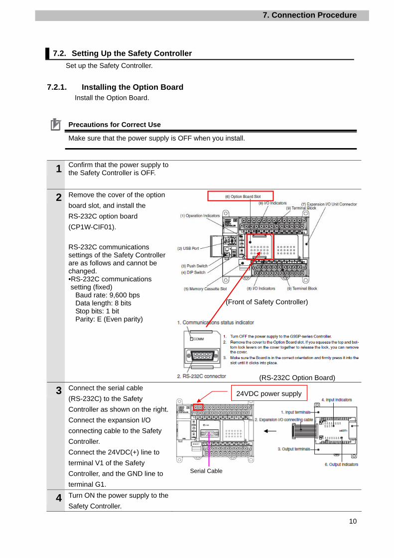
2 Remove the cover of the option
board slot, and install the
RS-232C option board
(CP1W-CIF01).
RS-232C communications settings of the Safety Controller are as follows and cannot be changed. •RS-232C communications setting (fixed)
Baud rate: 9,600 bps Data length: 8 bits Stop bits: 1 bit Parity: E (Even parity)
(Front of Safety Controller)
(RS-232C Option Board)
3 Connect the serial cable
(RS-232C) to the Safety
Controller as shown on the right.
Connect the expansion I/O
connecting cable to the Safety
Controller.
Connect the 24VDC(+) line to
terminal V1 of the Safety
Controller, and the GND line to
terminal G1.
4 Turn ON the power supply to the
Safety Controller.
24VDC power supply
Serial Cable
7. Connection Procedure
11
7.3. Setting Up the Controller
Set up the Controller.
7.3.1. Hardware Settings of the Serial Communications Unit Set the hardware switches on the Serial Communications Unit.
Precautions for Correct Use
Make sure that the power supply is OFF when you perform the setting up.
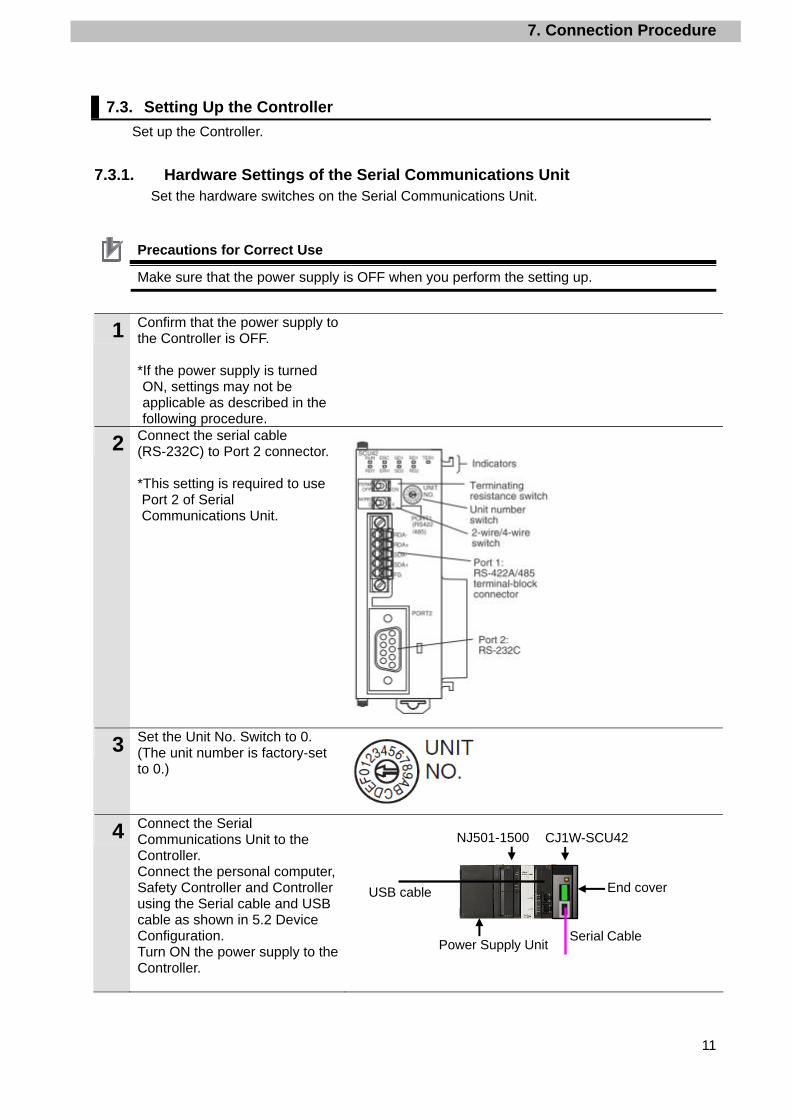
1 Confirm that the power supply to the Controller is OFF. *If the power supply is turned ON, settings may not be applicable as described in the following procedure.
2 Connect the serial cable (RS-232C) to Port 2 connector. *This setting is required to use Port 2 of Serial Communications Unit.
3 Set the Unit No. Switch to 0. (The unit number is factory-set to 0.)
4 Connect the Serial Communications Unit to the Controller. Connect the personal computer, Safety Controller and Controller using the Serial cable and USB cable as shown in 5.2 Device Configuration. Turn ON the power supply to the Controller.
CJ1W-SCU42
USB cable
NJ501-1500
End cover
Power Supply UnitSerial Cable

7. Connection Procedure
12
7.3.2. Starting the Sysmac Studio and Importing the Project File Start the Sysmac Studio, and import the Sysmac Studio project file.
Install the programming software and USB driver in the personal computer beforehand.
1 Start the Sysmac Studio.
Click the Import Button.
*If a confirmation dialog for an
access right is displayed at
start, select to start.
2 The Import File Dialog Box is
displayed. Select
OMRON_G9SP_SERI232_LD_
EV100.smc (Sysmac Studio
project file) and click the Open
Button.
*Obtain the Sysmac Studio
project file from OMRON.
3 OMRON_G9SP_SERI232_LD_
EV100 project is displayed.
The left pane is called Multiview
Explorer, the right pane is called
Toolbox and the middle pane is
called Edit Pane.
Multiview Explorer
Edit Pane Toolbox
7. Connection Procedure
13
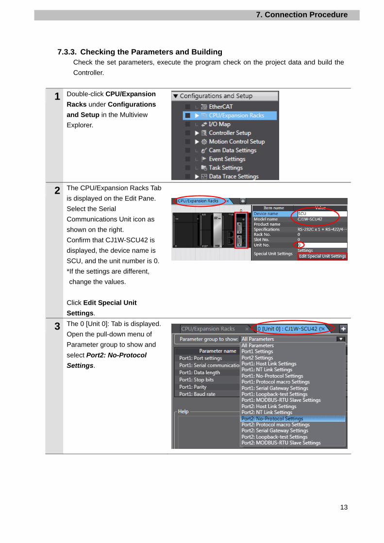
7.3.3. Checking the Parameters and Building Check the set parameters, execute the program check on the project data and build the
Controller.
1 Double-click CPU/Expansion
Racks under Configurations
and Setup in the Multiview
Explorer.
2 The CPU/Expansion Racks Tab
is displayed on the Edit Pane.
Select the Serial
Communications Unit icon as
shown on the right.
Confirm that CJ1W-SCU42 is
displayed, the device name is
SCU, and the unit number is 0.
*If the settings are different,
change the values.
Click Edit Special Unit
Settings.
3 The 0 [Unit 0]: Tab is displayed.
Open the pull-down menu of
Parameter group to show and
select Port2: No-Protocol
Settings.

7. Connection Procedure
14
4 Parameter group to show is set
to Port 2: No-Protocol Settings.
The items of the Port 2:
No-Protocol Settings are
displayed.
Confirm that the Port2: Port
settings is set to User settings
and other items are the same as
Section 6.1.
*If the settings are different from
the above, change the values
from the pull-down menu. Click
the Apply Button after
changing values.
5 Double-click I/O Map under
Configurations and Setup on
the Multiview Explorer.
The I/O Map Tab Page is
displayed and the parameters of
the Unit are displayed.
6 Confirm that the data in the
Variable Columns on the I/O
Map Tab Page start with SCU
and that the Global Variables
are set in the Variable Type
Columns.
*If the settings are different from
the above, right-click on
CJ1W-SCU42 and select
Create Device Variable.
7 Double-click the Task Settings
under Configurations and
Setup in the Multiview Explorer.
7. Connection Procedure
15
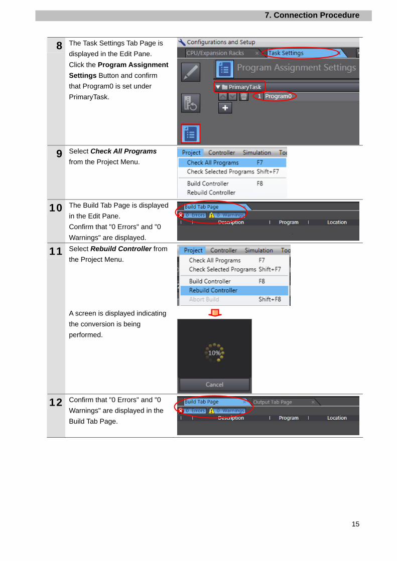
8 The Task Settings Tab Page is
displayed in the Edit Pane.
Click the Program Assignment
Settings Button and confirm
that Program0 is set under
PrimaryTask.
9 Select Check All Programs
from the Project Menu.
10 The Build Tab Page is displayed
in the Edit Pane.
Confirm that "0 Errors" and "0
Warnings" are displayed.
11 Select Rebuild Controller from
the Project Menu.
A screen is displayed indicating
the conversion is being
performed.
12 Confirm that "0 Errors" and "0
Warnings" are displayed in the
Build Tab Page.
7. Connection Procedure
16
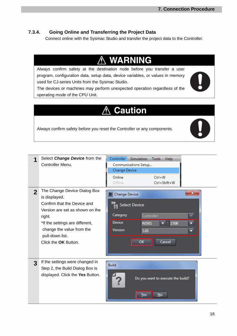
7.3.4. Going Online and Transferring the Project Data Connect online with the Sysmac Studio and transfer the project data to the Controller.
Always confirm safety at the destination node before you transfer a user
program, configuration data, setup data, device variables, or values in memory
used for CJ-series Units from the Sysmac Studio.
The devices or machines may perform unexpected operation regardless of the
operating mode of the CPU Unit.
Always confirm safety before you reset the Controller or any components.
1 Select Change Device from the
Controller Menu.
2 The Change Device Dialog Box
is displayed.
Confirm that the Device and
Version are set as shown on the
right.
*If the settings are different,
change the value from the
pull-down list.
Click the OK Button.
3 If the settings were changed in
Step 2, the Build Dialog Box is
displayed. Click the Yes Button.

7. Connection Procedure
17
4 Select the Communications Setup from the Controller Menu.
5 The Communications Setup
Dialog Box is displayed.
Select the Direct Connection via
USB Option in the Connection
Type Field.
Click the OK Button.
6 Select Online from the
Controller Menu.
A confirmation dialog box is
displayed. Click the Yes Button.
*The displayed dialog depends on the status of the Controller used. Select the Yes Button to proceed with the processing.
Additional Information For details on online connections to a Controller, refer to Section 5 Going Online with a Controller in the Sysmac Studio Version 1.0 Operation Manual (Cat. No. W504).
7 When an online connection is
established, a yellow bar is
displayed on the top of the Edit
Pane.
8 Select Synchronization from
the Controller Menu.

7. Connection Procedure
18
9 The Synchronization Dialog Box
is displayed.
Confirm that the data to transfer
(NJ501 in the right figure) is
selected. Then, click the
Transfer to Controller Button.
10 A confirmation dialog is
displayed. Click the Yes Button.
A screen stating "Synchronizing"
is displayed.
A confirmation dialog box is
displayed. Click the No Button.
11 Confirm that the synchronized
data is displayed with the color
specified by “Synchronized” and
that a message is displayed
stating "The synchronization
process successfully finished".
If there is no problem, click the
Close Button.
*If the synchronization fails,
check the wiring and repeat the
procedure described in this
section.
7. Connection Procedure
19
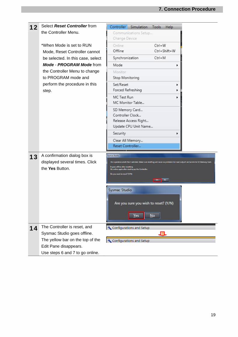
12 Select Reset Controller from
the Controller Menu.
*When Mode is set to RUN
Mode, Reset Controller cannot
be selected. In this case, select
Mode - PROGRAM Mode from
the Controller Menu to change
to PROGRAM mode and
perform the procedure in this
step.
13 A confirmation dialog box is
displayed several times. Click
the Yes Button.
14 The Controller is reset, and
Sysmac Studio goes offline.
The yellow bar on the top of the
Edit Pane disappears.
Use steps 6 and 7 to go online.
7. Connection Procedure
20
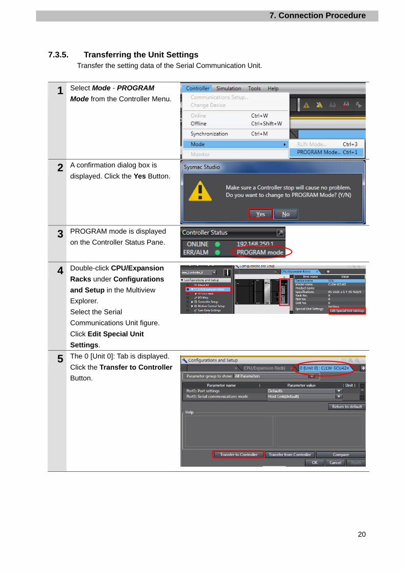
7.3.5. Transferring the Unit Settings Transfer the setting data of the Serial Communication Unit.
1 Select Mode - PROGRAM
Mode from the Controller Menu.
2 A confirmation dialog box is
displayed. Click the Yes Button.
3 PROGRAM mode is displayed
on the Controller Status Pane.
4 Double-click CPU/Expansion
Racks under Configurations
and Setup in the Multiview
Explorer.
Select the Serial
Communications Unit figure.
Click Edit Special Unit
Settings.
5 The 0 [Unit 0]: Tab is displayed.
Click the Transfer to Controller
Button.
7. Connection Procedure
21
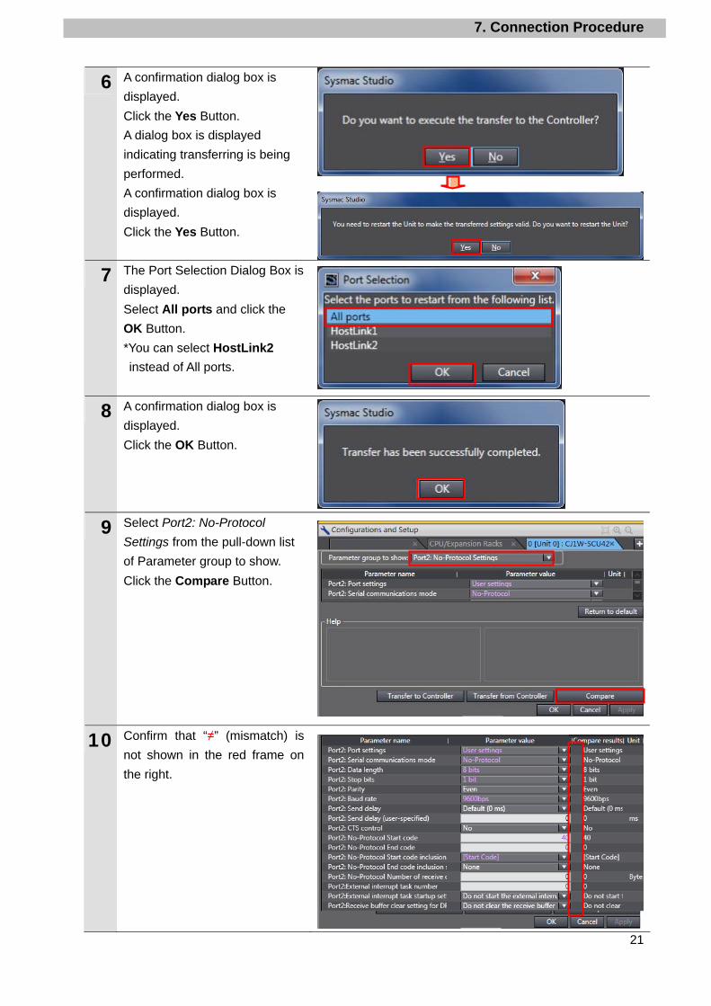
6 A confirmation dialog box is
displayed.
Click the Yes Button.
A dialog box is displayed
indicating transferring is being
performed.
A confirmation dialog box is
displayed.
Click the Yes Button.
7 The Port Selection Dialog Box is
displayed.
Select All ports and click the
OK Button.
*You can select HostLink2
instead of All ports.
8 A confirmation dialog box is
displayed.
Click the OK Button.
9 Select Port2: No-Protocol
Settings from the pull-down list
of Parameter group to show.
Click the Compare Button.
10 Confirm that “≠” (mismatch) is
not shown in the red frame on
the right.

7. Connection Procedure
22
7.4. Connection Status Check
Execute the project file that was transferred and confirm that serial communications are
performed normally.
Sufficiently confirm safety before you change the values of variables on a Watch
Tab Page when the Sysmac Studio is online with the CPU Unit. Incorrect
operation may cause the devices that are connected to Output Units to operate
regardless of the operating mode of the Controller.
Precautions for Correct Use
Please confirm that the serial cable is connected before proceeding to the following steps.
If it is not connected, turn OFF the power of the devices, and then connect the serial cable.
7.4.1. Executing the Ladder Program and Checking the Receive Data Execute the ladder program and confirm that the correct data are written to the variables of
the Controller.
1 Select Mode - RUN Mode from the
Controller Menu.
A confirmation dialog box is
displayed. Click the Yes Button.
2 RUN mode is displayed on the
Controller Status Pane.
3 Select Watch Tab Page from the
View Menu.

7. Connection Procedure
23
4 The Watch Tab Page is displayed in the lower section of the Edit Pane.
5 Confirm that the following values are displayed in the Name Columns.
Input_Start Output_Status Output_ErrorCode1 Output_ErrorCode2 G9SP_ResponseData[0-198] G9SP_CommandData
*If the necessary variables are not displayed, click Input Name to add.
6 Click TRUE on the Modify Column
of Input_Start.
The Online value of Input_Start
changes to True.
The Online Values of Output Status
and etc. are initialized to FFFF.
When serial communications are
completed normally, the Online
Values of Output Status and etc.
change to 0000.
7 The response data that was received are stored in G9SP_ResponseData[0] to [198]. Specify variables you want to see in the Watch Tab Page as shown in the right figure and check them. If values are stored in G9SP_ResponseData[2] to [5] as shown on the right, the operation is completed normally.
G9SP_ResponseData[2]:C3 G9SP_ResponseData[3]:00 G9SP_ResponseData[4]:00 G9SP_ResponseData[5]:CB
←Response length
←End code (H)
←End code (L)
←Service code
←Communicationssend data
←Same as above
←Same as above
←Same as above

8. Initialization Method
24
8. Initialization Method
This document explains the setting procedure from the factory default setting.
Some settings may not be applicable as described in this document unless you use the
devices with the factory default setting.
8.1. Initializing the Controller
To initialize the Controller, it is necessary to initialize the CPU Unit and Serial Communications
Unit.
8.1.1. CPU Unit To initialize the settings of the Controller, select Clear All Memory from the Controller
Menu of the Sysmac Studio.
8. Initialization Method
25
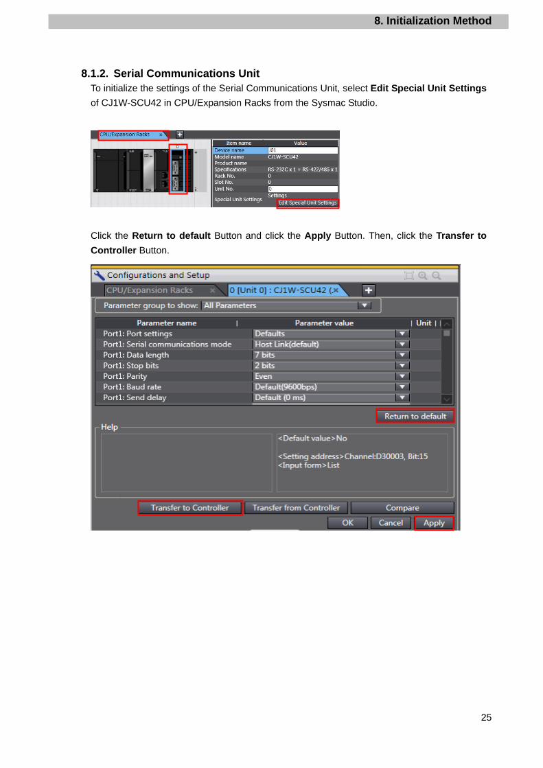
8.1.2. Serial Communications Unit To initialize the settings of the Serial Communications Unit, select Edit Special Unit Settings
of CJ1W-SCU42 in CPU/Expansion Racks from the Sysmac Studio.
Click the Return to default Button and click the Apply Button. Then, click the Transfer to
Controller Button.
9. Project File
26
9. Project File
This section describes the details on the project file used in this document.
9.1. Overview
This section explains the specifications and functions of the project file used to connect the
Safety Controller (hereinafter referred to as the destination device or G9SP) to the Controller
(Serial Communications Unit) (hereinafter referred to as an SCU Unit).
The project file means a Sysmac Studio project file.
The following data has already been set in this project file.
·SCU Unit communications settings and program task settings
·Ladder program for serial communications
·Variable tables and data type definitions of the variables used in ladder programs
This project file uses the serial communications of the SCU Unit to execute “read the I/O
monitor results” on the destination device and to detect whether the operation ends normally
or abnormally.
A normal end of this project file means a normal end of that the serial communications.
An error end means an error end of the serial communications and a destination device error
(Detected with the response data from the destination device).
Additional Information OMRON has confirmed that normal communications can be performed using this project file under the OMRON evaluation conditions including the test system configuration, version of each product, and product Lot, No. of each device which was used for evaluation. OMRON does not guarantee the normal operation under the disturbance such as electrical noise or the performance variation of the device.
Additional Information With Sysmac Studio, the “data type + #” prefix is added to decimal data and “data type + # + 16 + #" prefix is added to hexadecimal data when it is necessary to distinguish between decimal and hexadecimal data. (e.g., INT#1000 decimal -> INT#16#03E8 hexadecimal. For DINT, a data type + "#" are unnecessary.)
9. Project File
27
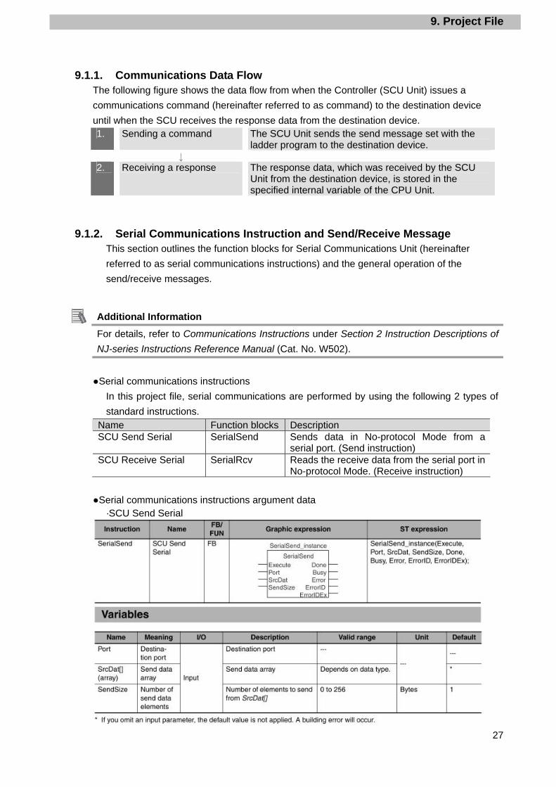
9.1.1. Communications Data Flow The following figure shows the data flow from when the Controller (SCU Unit) issues a
communications command (hereinafter referred to as command) to the destination device
until when the SCU receives the response data from the destination device. 1. Sending a command The SCU Unit sends the send message set with the
ladder program to the destination device. ↓
2. Receiving a response The response data, which was received by the SCU Unit from the destination device, is stored in the specified internal variable of the CPU Unit.
9.1.2. Serial Communications Instruction and Send/Receive Message This section outlines the function blocks for Serial Communications Unit (hereinafter
referred to as serial communications instructions) and the general operation of the
send/receive messages.
Additional Information For details, refer to Communications Instructions under Section 2 Instruction Descriptions of
NJ-series Instructions Reference Manual (Cat. No. W502).
●Serial communications instructions
In this project file, serial communications are performed by using the following 2 types of
standard instructions. Name Function blocks Description SCU Send Serial SerialSend Sends data in No-protocol Mode from a
serial port. (Send instruction) SCU Receive Serial SerialRcv Reads the receive data from the serial port in
No-protocol Mode. (Receive instruction)
●Serial communications instructions argument data ·SCU Send Serial
9. Project File
28
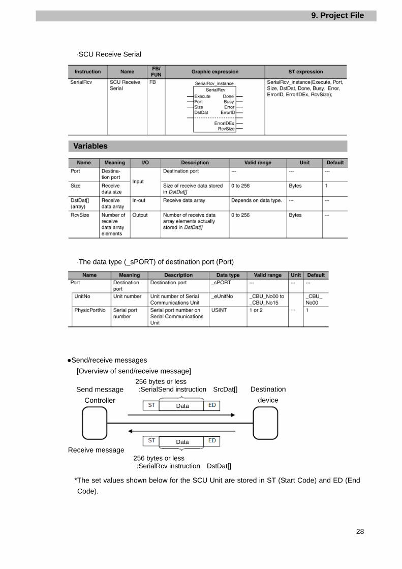
·SCU Receive Serial
·The data type (_sPORT) of destination port (Port)
●Send/receive messages
[Overview of send/receive message]
*The set values shown below for the SCU Unit are stored in ST (Start Code) and ED (End
Code).
Destination
device
Send message
Controller
256 bytes or less :SerialSend instruction SrcDat[]
Data
DataReceive message
256 bytes or less :SerialRcv instruction DstDat[]
9. Project File
29
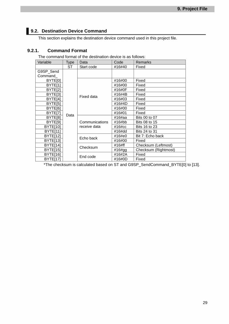
9.2. Destination Device Command
This section explains the destination device command used in this project file.
9.2.1. Command Format The command format of the destination device is as follows: Variable Type Data Code Remarks
ST Start code #16#40 Fixed G9SP_SendCommand_
BYTE[0] #16#00 Fixed BYTE[1] #16#00 Fixed BYTE[2] #16#0F Fixed BYTE[3] #16#4B Fixed BYTE[4] #16#03 Fixed BYTE[5] #16#4D Fixed BYTE[6] #16#00 Fixed BYTE[7]
Fixed data
#16#01 Fixed BYTE[8] #16#aa Bits 00 to 07 BYTE[9] #16#bb Bits 08 to 15
BYTE[10] #16#cc Bits 16 to 23 BYTE[11]
Communications receive data
#16#dd Bits 24 to 31 BYTE[12] #16#e0 Bit 7: Echo back BYTE[13]
Echo back #16#00 Fixed
BYTE[14] #16#ff Checksum (Leftmost) BYTE[15]
Checksum #16#gg Checksum (Rightmost)
BYTE[16] #16#2A Fixed BYTE[17]
Data
End code #16#0D Fixed
*The checksum is calculated based on ST and G9SP_SendCommand_BYTE[0] to [13].
9. Project File
30
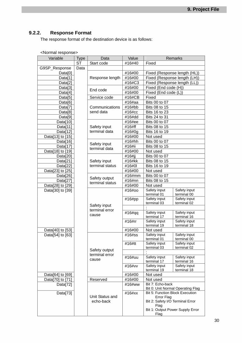
9.2.2. Response Format The response format of the destination device is as follows:
<Normal response> Variable Type Data Value Remarks
ST Start code #16#40 Fixed G9SP_Response
Data[0] #16#00 Fixed (Response length (HL)) Data[1] #16#00 Fixed (Response length (LH)) Data[2]
Response length#16#C3 Fixed (Response length (LL))
Data[3] #16#00 Fixed (End code (H)) Data[4]
End code #16#00 Fixed (End code (L))
Data[5] Service code #16#CB Fixed Data[6] #16#aa Bits 00 to 07 Data[7] #16#bb Bits 08 to 15 Data[8] #16#cc Bits 16 to 23 Data[9]
Communications send data
#16#dd Bits 24 to 31 Data[10] #16#ee Bits 00 to 07 Data[11] #16#ff Bits 08 to 15 Data[12] #16#0g Bits 16 to 19
Data[13] to [15]
Safety input terminal data
#16#00 Not used Data[16] #16#hh Bits 00 to 07 Data[17] #16#ii Bits 08 to 15
Data[18] to [19]
Safety input terminal data
#16#00 Not used Data[20] #16#jj Bits 00 to 07 Data[21] #16#kk Bits 08 to 15 Data[22] #16#0l Bits 16 to 19
Data[23] to [25]
Safety input terminal status
#16#00 Not used Data[26] #16#mm Bits 00 to 07 Data[27] #16#nn Bits 08 to 15
Data[28] to [29]
Safety output terminal status
#16#00 Not used #16#oo Safety input
terminal 01 Safety input terminal 00
#16#pp Safety input terminal 03
Safety input terminal 02
: #16#qq Safety input
terminal 17 Safety input terminal 16
Data[30] to [39]
#16#rr Safety input terminal 19
Safety input terminal 18
Data[40] to [53]
Safety input terminal error cause
#16#00 Not used #16#ss Safety input
terminal 01 Safety input terminal 00
#16#tt Safety input terminal 03
Safety input terminal 02
: #16#uu Safety input
terminal 17 Safety input terminal 16
Data[54] to [63]
#16#vv Safety input terminal 19
Safety input terminal 18
Data[64] to [69]
Safety output terminal error cause
#16#00 Not used Data[70] to [71] Reserved #16#00 Not used
Data[72] #16#ww Bit 7: Echo-back Bit 0: Unit Normal Operating Flag
Data[73]
Data
Unit Status and echo-back
#16#xx Bit 5: Function Block Execution Error Flag
Bit 2: Safety I/O Terminal Error Flag
Bit 1: Output Power Supply Error Flag

9. Project File
31
Variable Type Data Value Remarks Data[74] #16#yy Rightmost byte Data[75]
Configuration ID#16#zz Leftmost byte
Data[76] #16#aa First byte Data[77] #16#bb Second byte Data[78] #16#cc Third byte Data[79]
Unit Conduction Time
#16#00 Not used Data[80] to [99] Reserved #16#00 Not used
#16#dd Error Information Map 0
#16#ee Error Information Map 1 : #16#ff Error Information Map 10
Data[100] to [111]
Present Error Information
#16#gg Error Information Map 11
Data[112] #16#hh Error Log Count Data[113]
Error Log Count (Operation Log Count)
#16#ii Operation Log Count
#16#jj Error code 1 #16#kk Conduction Time first byte at
error #16#ll Conduction Time second byte at
error #16#mm
Conduction Time third byte at error
: : #16#nn Error code 10 #16#oo Conduction Time first byte at
error #16#pp Conduction Time second byte at
error
Data[114] to [153]
Error Log (Error Code: Conduction Time)
#16#qq Conduction Time third byte at error
#16#rr Operation code 1 #16#ss Conduction Time first byte at
error #16#tt Conduction Time second byte at
error #16#uu Conduction Time third byte at
error : : #16#vv Operation code 10 #16#ww
Conduction Time first byte at error
#16#xx Conduction Time second byte at error
Data[154] to [193]
Operation Log (Operation Code: Conduction Time)
#16#yy Conduction Time third byte at error
Data[194] #16#zz Checksum (Leftmost) Data[195]
Checksum #16#aa Checksum (Rightmost)
Data[196] #16#2A Fixed Data[197]
End code #16#0D Fixed
*The checksum is calculated based on ST and G9SP_ResponseData[0] to [193].
*The response length is calculated based on G9SP_ResponseData[3] to [197].
9. Project File
32
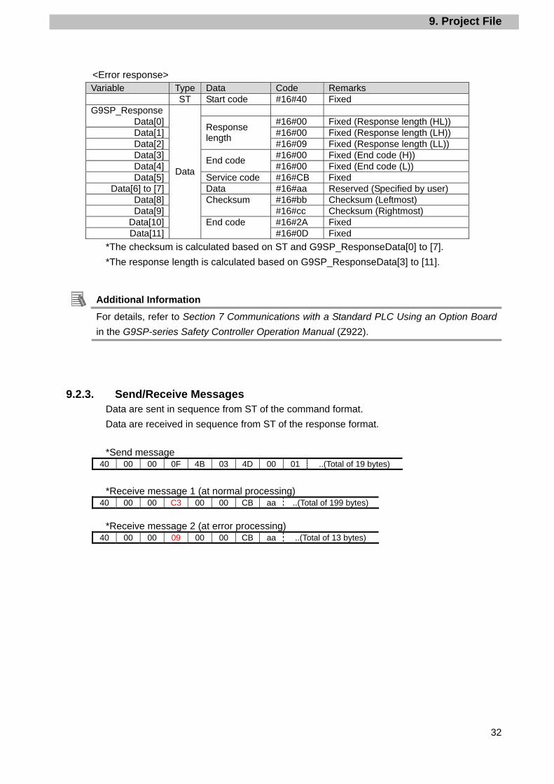
<Error response> Variable Type Data Code Remarks
ST Start code #16#40 Fixed G9SP_Response
Data[0] #16#00 Fixed (Response length (HL)) Data[1] #16#00 Fixed (Response length (LH)) Data[2]
Response length
#16#09 Fixed (Response length (LL)) Data[3] #16#00 Fixed (End code (H)) Data[4]
End code #16#00 Fixed (End code (L))
Data[5] Service code #16#CB Fixed Data[6] to [7] Data #16#aa Reserved (Specified by user)
Data[8] #16#bb Checksum (Leftmost) Data[9]
Checksum #16#cc Checksum (Rightmost)
Data[10] #16#2A Fixed Data[11]
Data
End code #16#0D Fixed
*The checksum is calculated based on ST and G9SP_ResponseData[0] to [7].
*The response length is calculated based on G9SP_ResponseData[3] to [11].
Additional Information For details, refer to Section 7 Communications with a Standard PLC Using an Option Board
in the G9SP-series Safety Controller Operation Manual (Z922).
9.2.3. Send/Receive Messages Data are sent in sequence from ST of the command format.
Data are received in sequence from ST of the response format.
*Send message
40 00 00 0F 4B 03 4D 00 01 ..(Total of 19 bytes)
*Receive message 1 (at normal processing)
40 00 00 C3 00 00 CB aa ..(Total of 199 bytes)
*Receive message 2 (at error processing)
40 00 00 09 00 00 CB aa ..(Total of 13 bytes)
9. Project File
33
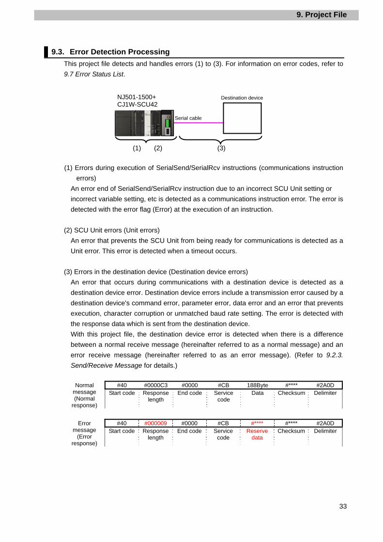
9.3. Error Detection Processing
This project file detects and handles errors (1) to (3). For information on error codes, refer to
9.7 Error Status List.
(1) Errors during execution of SerialSend/SerialRcv instructions (communications instruction
errors)
An error end of SerialSend/SerialRcv instruction due to an incorrect SCU Unit setting or
incorrect variable setting, etc is detected as a communications instruction error. The error is
detected with the error flag (Error) at the execution of an instruction.
(2) SCU Unit errors (Unit errors)
An error that prevents the SCU Unit from being ready for communications is detected as a
Unit error. This error is detected when a timeout occurs.
(3) Errors in the destination device (Destination device errors)
An error that occurs during communications with a destination device is detected as a
destination device error. Destination device errors include a transmission error caused by a
destination device's command error, parameter error, data error and an error that prevents
execution, character corruption or unmatched baud rate setting. The error is detected with
the response data which is sent from the destination device.
With this project file, the destination device error is detected when there is a difference
between a normal receive message (hereinafter referred to as a normal message) and an
error receive message (hereinafter referred to as an error message). (Refer to 9.2.3.
Send/Receive Message for details.)
#40 #0000C3 #0000 #CB 188Byte #**** #2A0D Normal
message (Normal
response)
Start code Response length
End code Service code
Data Checksum Delimiter
#40 #000009 #0000 #CB #**** #**** #2A0D Error
message (Error
response)
Start code Response length
End code Service code
Reserve data
Checksum Delimiter
Serial cable
Destination device
(1) (2) (3)
NJ501-1500+ CJ1W-SCU42
9. Project File
34
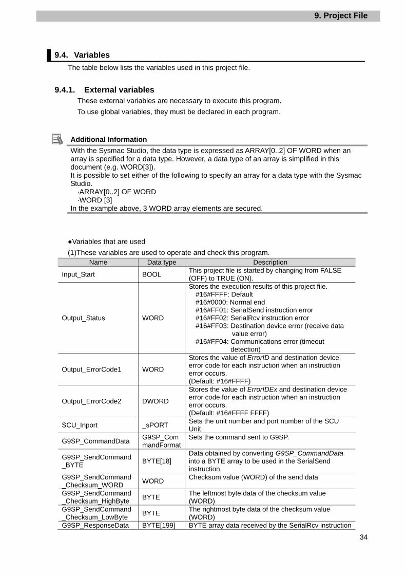
9.4. Variables
The table below lists the variables used in this project file.
9.4.1. External variables These external variables are necessary to execute this program.
To use global variables, they must be declared in each program.
Additional Information With the Sysmac Studio, the data type is expressed as ARRAY[0..2] OF WORD when an array is specified for a data type. However, a data type of an array is simplified in this document (e.g. WORD[3]). It is possible to set either of the following to specify an array for a data type with the Sysmac Studio.
·ARRAY[0..2] OF WORD ·WORD [3]
In the example above, 3 WORD array elements are secured.
●Variables that are used
(1)These variables are used to operate and check this program. Name Data type Description
Input_Start BOOL This project file is started by changing from FALSE (OFF) to TRUE (ON).
Output_Status WORD
Stores the execution results of this project file. #16#FFFF: Default #16#0000: Normal end #16#FF01: SerialSend instruction error #16#FF02: SerialRcv instruction error #16#FF03: Destination device error (receive data
value error) #16#FF04: Communications error (timeout
detection)
Output_ErrorCode1 WORD
Stores the value of ErrorID and destination device error code for each instruction when an instruction error occurs. (Default: #16#FFFF)
Output_ErrorCode2 DWORD
Stores the value of ErrorIDEx and destination device error code for each instruction when an instruction error occurs. (Default: #16#FFFF FFFF)
SCU_Inport _sPORT Sets the unit number and port number of the SCU Unit.
G9SP_CommandData G9SP_CommandFormat
Sets the command sent to G9SP.
G9SP_SendCommand_BYTE
BYTE[18] Data obtained by converting G9SP_CommandData into a BYTE array to be used in the SerialSend instruction.
G9SP_SendCommand_Checksum_WORD
WORD Checksum value (WORD) of the send data
G9SP_SendCommand_Checksum_HighByte
BYTE The leftmost byte data of the checksum value (WORD)
G9SP_SendCommand_Checksum_LowByte
BYTE The rightmost byte data of the checksum value (WORD)
G9SP_ResponseData BYTE[199] BYTE array data received by the SerialRcv instruction

9. Project File
35
(2)These variables of the SCU Unit are used in this program. Name Data type Description
SCU_P2_NopSerialSendExecSta
BOOL SerialSend instruction executing flag:
ON during data send operation and OFF when the send operation is completed.
SCU_P2_NopRcvCompleteSta
BOOL
Receive completion flag: ON when reception of data is completed and OFF when storing the receive data in a variable specified with the SerialRcv is completed.
SCU_P2_NopRcvCntSta
UINT Receive counter: Stores the size of the received data.
Additional Information For information on variables of the Serial Communications Unit, refer to 5-2 Device Variables
for CJ-series Unit and System-defined Variables (During Serial Gateway Mode) in the CJ-series Serial Communications Units Operation Manual for NJ-series CPU Unit (Cat.No. W494).
(3)This system variable is used in this program. Name Data type Description
_Port_isAvailable BOOL Communications Port Enabled Flag
Additional Information
For information on system variables when using the serial communications instructions, refer to SerialSend and SerialRecv in Section 2 Instruction Descriptions of the NJ-series Instructions Reference Manual (Cat. No. W502).
●Structure
The structures used in the external variables are shown below.
(1)_sPORT Variable Meaning Description Data type Valid range Default
SCU_Inport Destination port
Destination port _sPORT -
UnitNo Unit number Unit number of SCU Unit
_eUnitNo _CBU_No00 to _CBU_No15
_CBU_No00
PhysicPortNo
Serial port number
Serial port number of SCU Unit
USINT 1 or 2 1
(2)G9SP_CommandFormat Variable Meaning Description Data type Valid range Default
G9SP_CommandFormat
G9SP command setting
Specifies command data sent to G9SP.
G9SP_CommandFormat
-
FixationArea1 Fixed area 1 Sets the fixed data that cannot be changed by the user.
USINT[8] Fixed -
SendData User specification area
Sets communications receive data and echo back data that can be changed by the user.
USINT[6] #16#00 to 16#FF
-
CheckSum Checksum area
Sets a checksum value. UINT #16#00 to #16#FF
-
FixationArea2 End code area
Sets the end code (#16#2A0D).
USINT[2] Fixed -
9. Project File
36
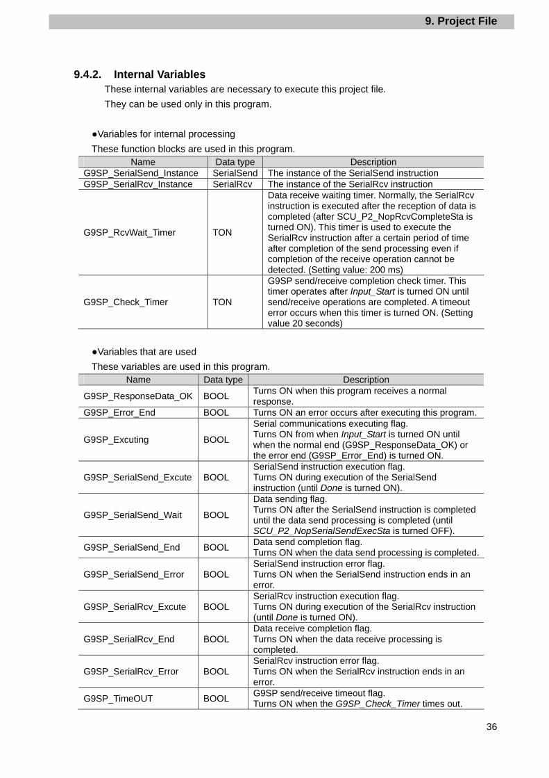
9.4.2. Internal Variables These internal variables are necessary to execute this project file.
They can be used only in this program.
●Variables for internal processing
These function blocks are used in this program. Name Data type Description
G9SP_SerialSend_Instance SerialSend The instance of the SerialSend instruction G9SP_SerialRcv_Instance SerialRcv The instance of the SerialRcv instruction
G9SP_RcvWait_Timer TON
Data receive waiting timer. Normally, the SerialRcv instruction is executed after the reception of data is completed (after SCU_P2_NopRcvCompleteSta is turned ON). This timer is used to execute the SerialRcv instruction after a certain period of time after completion of the send processing even if completion of the receive operation cannot be detected. (Setting value: 200 ms)
G9SP_Check_Timer TON
G9SP send/receive completion check timer. This timer operates after Input_Start is turned ON until send/receive operations are completed. A timeout error occurs when this timer is turned ON. (Setting value 20 seconds)
●Variables that are used
These variables are used in this program. Name Data type Description
G9SP_ResponseData_OK BOOL Turns ON when this program receives a normal response.
G9SP_Error_End BOOL Turns ON an error occurs after executing this program.
G9SP_Excuting BOOL
Serial communications executing flag. Turns ON from when Input_Start is turned ON until when the normal end (G9SP_ResponseData_OK) or the error end (G9SP_Error_End) is turned ON.
G9SP_SerialSend_Excute BOOL SerialSend instruction execution flag. Turns ON during execution of the SerialSend instruction (until Done is turned ON).
G9SP_SerialSend_Wait BOOL
Data sending flag. Turns ON after the SerialSend instruction is completed until the data send processing is completed (until SCU_P2_NopSerialSendExecSta is turned OFF).
G9SP_SerialSend_End BOOL Data send completion flag. Turns ON when the data send processing is completed.
G9SP_SerialSend_Error BOOL SerialSend instruction error flag. Turns ON when the SerialSend instruction ends in an error.
G9SP_SerialRcv_Excute BOOL SerialRcv instruction execution flag. Turns ON during execution of the SerialRcv instruction (until Done is turned ON).
G9SP_SerialRcv_End BOOL Data receive completion flag. Turns ON when the data receive processing is completed.
G9SP_SerialRcv_Error BOOL SerialRcv instruction error flag. Turns ON when the SerialRcv instruction ends in an error.
G9SP_TimeOUT BOOL G9SP send/receive timeout flag. Turns ON when the G9SP_Check_Timer times out.
9. Project File
37
Name Data type Description
G9SP_ReceiveData_error BOOL Receive data error flag. Turns ON when the receive data is not normal.
9.5. Ladder Program
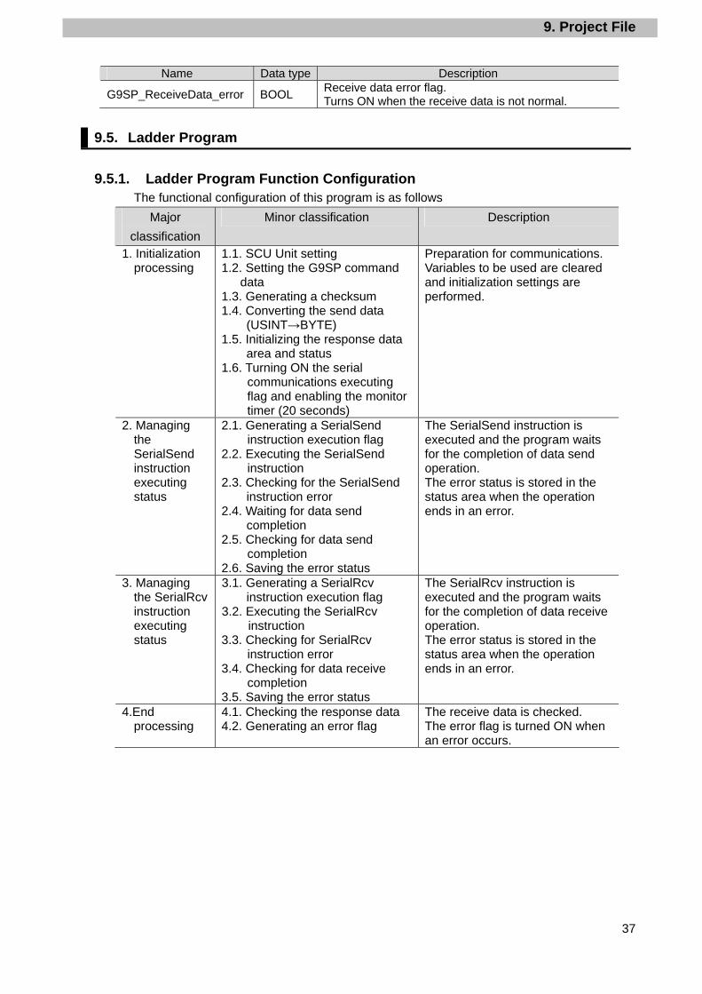
9.5.1. Ladder Program Function Configuration The functional configuration of this program is as follows
Major
classification
Minor classification Description
1. Initialization processing
1.1. SCU Unit setting 1.2. Setting the G9SP command
data 1.3. Generating a checksum 1.4. Converting the send data
(USINT→BYTE) 1.5. Initializing the response data
area and status 1.6. Turning ON the serial
communications executing flag and enabling the monitor timer (20 seconds)
Preparation for communications. Variables to be used are cleared and initialization settings are performed.
2. Managing the SerialSend instruction executing status
2.1. Generating a SerialSend instruction execution flag
2.2. Executing the SerialSend instruction
2.3. Checking for the SerialSend instruction error
2.4. Waiting for data send completion
2.5. Checking for data send completion
2.6. Saving the error status
The SerialSend instruction is executed and the program waits for the completion of data send operation. The error status is stored in the status area when the operation ends in an error.
3. Managing the SerialRcv instruction executing status
3.1. Generating a SerialRcv instruction execution flag
3.2. Executing the SerialRcv instruction
3.3. Checking for SerialRcv instruction error
3.4. Checking for data receive completion
3.5. Saving the error status
The SerialRcv instruction is executed and the program waits for the completion of data receive operation. The error status is stored in the status area when the operation ends in an error.
4.End processing
4.1. Checking the response data 4.2. Generating an error flag
The receive data is checked. The error flag is turned ON when an error occurs.

9. Project File
38
9.5.2. Explanation on Each Functional Component This section shows the details on the functions of this program.
1. Initialization processing
No. Overview Description
1.1. SCU Unit setting Sets the Unit number and serial port number of the SCU Unit
in the SCU_Inport structure.

9. Project File
39
No. Overview Description
1.2. Setting the G9SP
command data
Sets a command sent to G9SP.
Data in the red frame are communication receive data and
echo back data that can be changed by the user. Any value
can be set.
1.3. Generating a
checksum
Calculates the checksum value of the set command data.
9. Project File
40
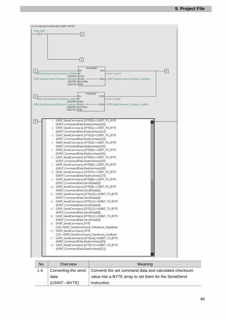
No. Overview Meaning
1.4. Converting the send
data
(USINT→BYTE)
Converts the set command data and calculated checksum
value into a BYTE array to set them for the SerialSend
instruction.
9. Project File
41
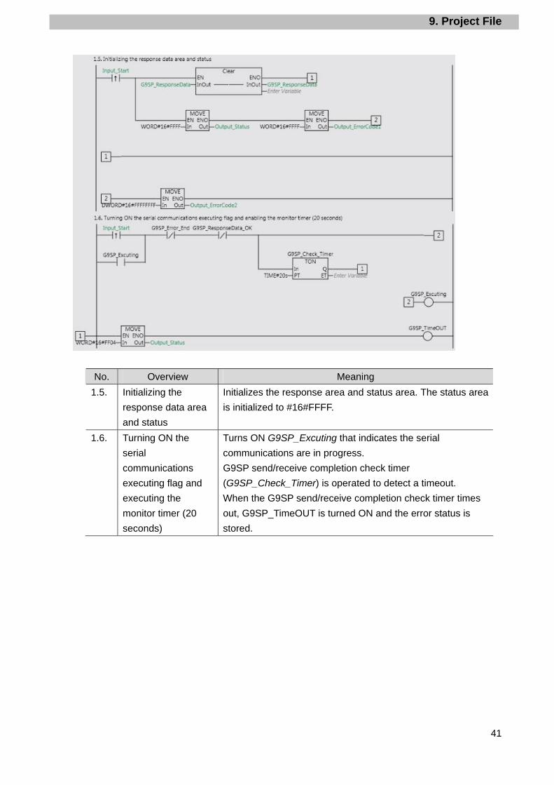
No. Overview Meaning
1.5. Initializing the
response data area
and status
Initializes the response area and status area. The status area
is initialized to #16#FFFF.
1.6. Turning ON the
serial
communications
executing flag and
executing the
monitor timer (20
seconds)
Turns ON G9SP_Excuting that indicates the serial
communications are in progress.
G9SP send/receive completion check timer
(G9SP_Check_Timer) is operated to detect a timeout.
When the G9SP send/receive completion check timer times
out, G9SP_TimeOUT is turned ON and the error status is
stored.
9. Project File
42
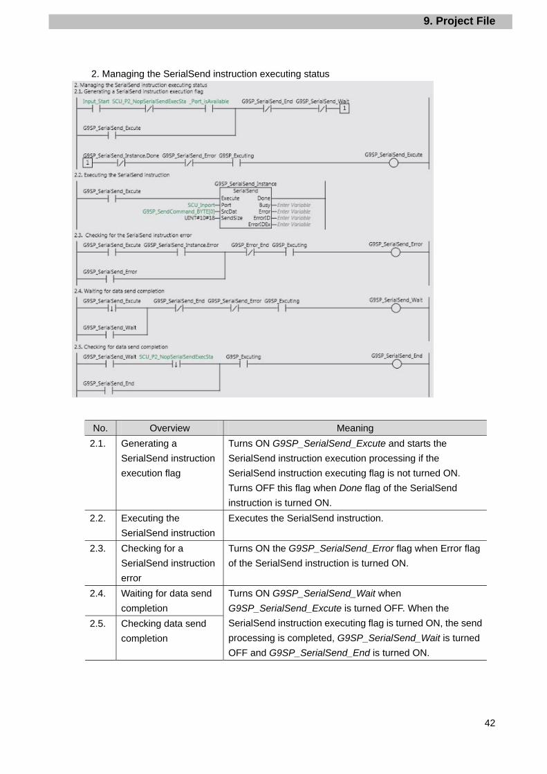
2. Managing the SerialSend instruction executing status
No. Overview Meaning
2.1. Generating a
SerialSend instruction
execution flag
Turns ON G9SP_SerialSend_Excute and starts the
SerialSend instruction execution processing if the
SerialSend instruction executing flag is not turned ON.
Turns OFF this flag when Done flag of the SerialSend
instruction is turned ON.
2.2. Executing the
SerialSend instruction
Executes the SerialSend instruction.
2.3. Checking for a
SerialSend instruction
error
Turns ON the G9SP_SerialSend_Error flag when Error flag
of the SerialSend instruction is turned ON.
2.4. Waiting for data send
completion
2.5. Checking data send
completion
Turns ON G9SP_SerialSend_Wait when
G9SP_SerialSend_Excute is turned OFF. When the
SerialSend instruction executing flag is turned ON, the send
processing is completed, G9SP_SerialSend_Wait is turned
OFF and G9SP_SerialSend_End is turned ON.

9. Project File
43
No. Overview Meaning
2.6. Saving error status Sets the following status when the SerialSend instruction
ends in an error.
·Output_Status: #16#FF01
·Output_ErrorCode1: ErrorID of SerialSend instruction
·Output_ErrorCode2: ErrorIDEx of SerialSend instruction
Additional Information For information on the error status, refer to 9.7 Error Status List.
9. Project File
44
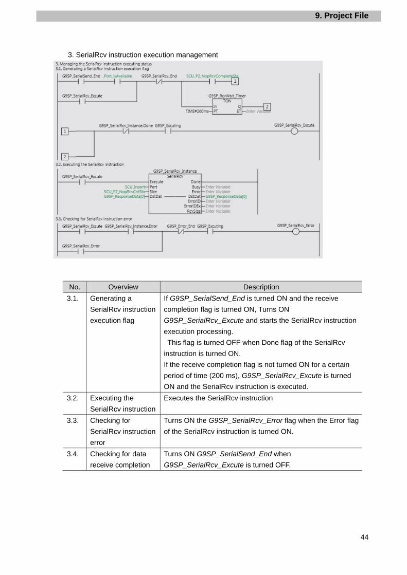
3. SerialRcv instruction execution management
No. Overview Description
3.1. Generating a
SerialRcv instruction
execution flag
If G9SP_SerialSend_End is turned ON and the receive
completion flag is turned ON, Turns ON
G9SP_SerialRcv_Excute and starts the SerialRcv instruction
execution processing.
This flag is turned OFF when Done flag of the SerialRcv
instruction is turned ON.
If the receive completion flag is not turned ON for a certain
period of time (200 ms), G9SP_SerialRcv_Excute is turned
ON and the SerialRcv instruction is executed.
3.2. Executing the
SerialRcv instruction
Executes the SerialRcv instruction
3.3. Checking for
SerialRcv instruction
error
Turns ON the G9SP_SerialRcv_Error flag when the Error flag
of the SerialRcv instruction is turned ON.
3.4. Checking for data
receive completion
Turns ON G9SP_SerialSend_End when
G9SP_SerialRcv_Excute is turned OFF.

9. Project File
45
No. Overview Meaning
3.4. Checking for data
receive completion
Turns ON G9SP_SerialSend_End when
G9SP_SerialRcv_Excute is turned OFF.
3.5. Saving the error
status
Sets the next status when the SerialRcv instruction ends in an
error.
·Output_Status: #16#FF02
·Output_ErrorCode1: ErrorID of SerialRcv instruction
·Output_ErrorCode2: ErrorIDEx of SerialRcv instruction
Additional Information For derails on the error status, refer to 9.7 Error Status List.

9. Project File
46
4. End processing
No. Overview Meaning
4.1. Checking if the
response data is
normal
Checks if the receive response data
(G9SP_ResponseData[2] to [5]) is the same as the fixed
data. If they are the same, the following data are set.
Output_Status: #16#0000
Output_ErrorCode1: #16#0000
Output_ErrorCode2: #16#00000000
G9SP_ResponseData_OK: ON
9. Project File
47
9. Project File
48
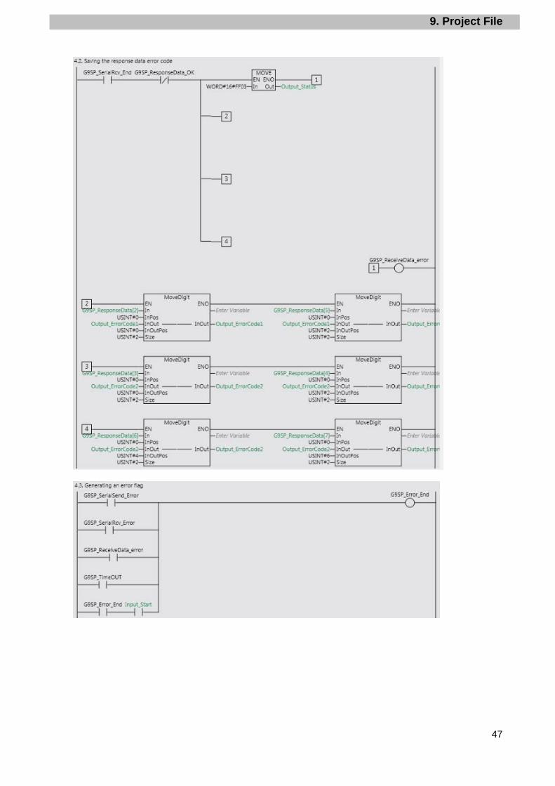
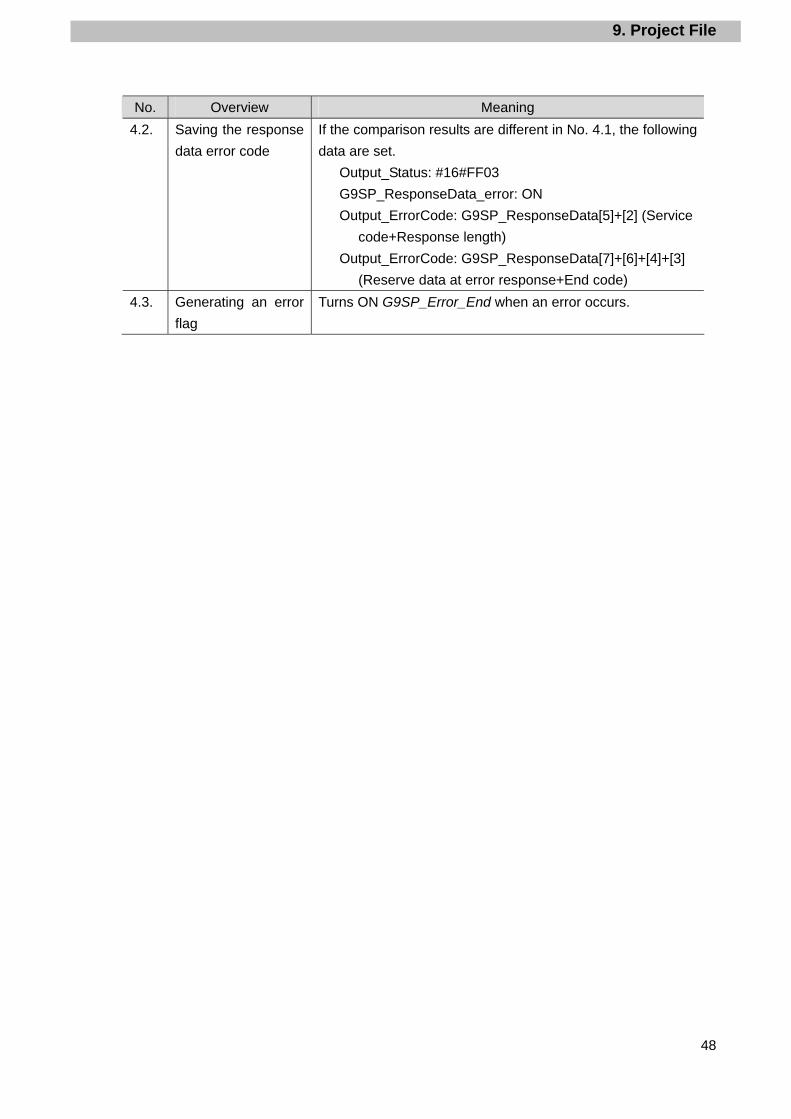
No. Overview Meaning
4.2. Saving the response
data error code
If the comparison results are different in No. 4.1, the following
data are set.
Output_Status: #16#FF03
G9SP_ResponseData_error: ON
Output_ErrorCode: G9SP_ResponseData[5]+[2] (Service
code+Response length)
Output_ErrorCode: G9SP_ResponseData[7]+[6]+[4]+[3]
(Reserve data at error response+End code)
4.3. Generating an error
flag
Turns ON G9SP_Error_End when an error occurs.
9. Project File
49
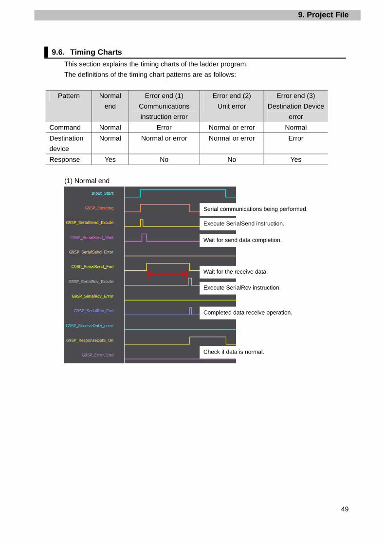
9.6. Timing Charts
This section explains the timing charts of the ladder program.
The definitions of the timing chart patterns are as follows:
Pattern Normal
end
Error end (1)
Communications
instruction error
Error end (2)
Unit error
Error end (3)
Destination Device
error
Command Normal Error Normal or error Normal
Destination
device
Normal Normal or error Normal or error Error
Response Yes No No Yes
(1) Normal end
Wait for send data completion.
Execute SerialSend instruction.
Wait for the receive data.
Execute SerialRcv instruction.
Completed data receive operation.
Check if data is normal.
Serial communications being performed.
9. Project File
50
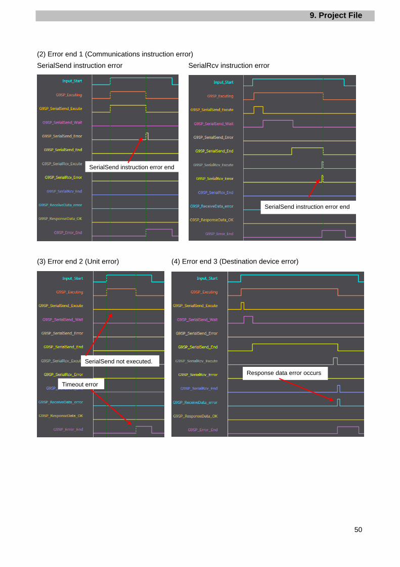
(2) Error end 1 (Communications instruction error)
SerialSend instruction error SerialRcv instruction error
(3) Error end 2 (Unit error) (4) Error end 3 (Destination device error)
SerialSend instruction error end
SerialSend instruction error end
SerialSend not executed.
Timeout error
Response data error occurs
9. Project File
51
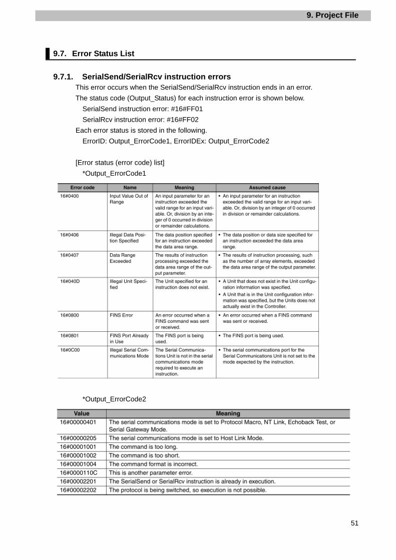
9.7. Error Status List
9.7.1. SerialSend/SerialRcv instruction errors This error occurs when the SerialSend/SerialRcv instruction ends in an error.
The status code (Output_Status) for each instruction error is shown below.
SerialSend instruction error: #16#FF01
SerialRcv instruction error: #16#FF02
Each error status is stored in the following.
ErrorID: Output_ErrorCode1, ErrorIDEx: Output_ErrorCode2
[Error status (error code) list]
*Output_ErrorCode1
*Output_ErrorCode2
9. Project File
52
Additional Information For details on the errors, refer to A-3 Error Code Details in the NJ-series Instructions
Reference Manual (Cat. No. W502).
For troubleshooting the errors, refer to 9-3 Troubleshooting in the CJ-series Serial
Communications Units Operation Manual for NJ-series CPU Unit (Cat.No. W494).
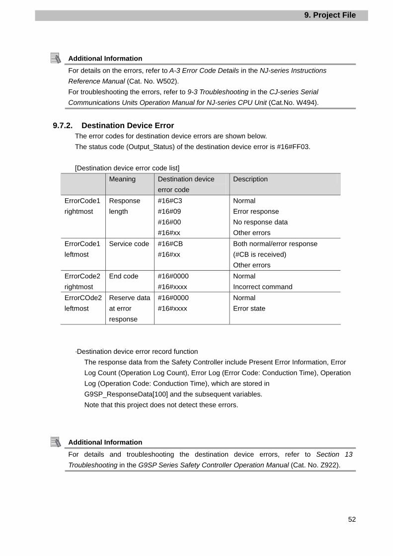
9.7.2. Destination Device Error The error codes for destination device errors are shown below.
The status code (Output_Status) of the destination device error is #16#FF03.
[Destination device error code list]
Meaning Destination device
error code
Description
ErrorCode1
rightmost
Response
length
#16#C3
#16#09
#16#00
#16#xx
Normal
Error response
No response data
Other errors
ErrorCode1
leftmost
Service code #16#CB
#16#xx
Both normal/error response
(#CB is received)
Other errors
ErrorCode2
rightmost
End code #16#0000
#16#xxxx
Normal
Incorrect command
ErrorCOde2
leftmost
Reserve data
at error
response
#16#0000
#16#xxxx
Normal
Error state
·Destination device error record function
The response data from the Safety Controller include Present Error Information, Error
Log Count (Operation Log Count), Error Log (Error Code: Conduction Time), Operation
Log (Operation Code: Conduction Time), which are stored in
G9SP_ResponseData[100] and the subsequent variables.
Note that this project does not detect these errors.
Additional Information For details and troubleshooting the destination device errors, refer to Section 13
Troubleshooting in the G9SP Series Safety Controller Operation Manual (Cat. No. Z922).

9. Project File
53

10. Revision History
54
10. Revision History
Revision
code
Date of revision Revision reason and revision page
01 Aug. 1, 2013 First edition

2013
1308**(-)P545-E1-01


