

Vers. 004
USE AND MAINTENANCE MANUAL AND
INSTRUCTIONS FOR INSTALLATION
GB
ENERGY 4004D
V. 007 – February 2008
GENERATORS
Energy 4004 D Vers. 007
GB
2
INDEX 1 FOREWORD ..................................................................................................................................... 4
1.1 Purpose and scope of this manual ............................................................................................. 4 1.2 Symbols and Definitions ............................................................................................................. 4 1.3 General Information .................................................................................................................... 4
2 GENERATING SET IDENTIFICATION DATA .................................................................................. 5 2.1 Components (Fig. 1) .................................................................................................................. 5 2.2 Identification label (Fig. 2)........................................................................................................... 5 2.3 Dimensions ................................................................................................................................. 5 2.4 Fiche technique .......................................................................................................................... 6
3 SHIPPING, HANDLING, STORAGE................................................................................................. 7 3.1 Storage ....................................................................................................................................... 7 3.2 Weight......................................................................................................................................... 7 3.3 Handling...................................................................................................................................... 7
4 INSTALLATION ................................................................................................................................ 7 4.1 Preliminary information ............................................................................................................... 7 4.2 Installing the generating set ........................................................................................................ 7
4.2.1 Exhaust connection.............................................................................................................. 8 4.3 Wiring connections ..................................................................................................................... 8 4.4 Battery connection ...................................................................................................................... 8 4.5 Electronic control panel connection ............................................................................................ 8 4.6 Optional fuel tank installation...................................................................................................... 9 4.7 Fuel reserve................................................................................................................................ 9
5 OPERATING INSTRUCTIONS ....................................................................................................... 10 5.1 Machine safety.......................................................................................................................... 10
6 USING THE GENERATING SET .................................................................................................... 10 6.1 Starting up ................................................................................................................................ 10 6.2 Turning off the generating set ................................................................................................... 11 6.3 Forbidden use........................................................................................................................... 11 6.4 Advice ....................................................................................................................................... 11 6.5 Control and alarm functions (Fig. 14) ....................................................................................... 11
7 MAINTENANCE INSTRUCTIONS .................................................................................................. 12 7.1 Maintenance list ........................................................................................................................ 12 7.2 Non specialist maintanance...................................................................................................... 12 7.3 Checking the motor oil level...................................................................................................... 12 7.4 Maintenance operations requiring specialised personnel ......................................................... 12
7.4.1 Motor oil replacement ........................................................................................................ 13 7.4.2 Air filter maintenance ......................................................................................................... 13 7.4.3 Replacing the oil filter......................................................................................................... 14
8 INSTRUCTIONS ON PUTTING OUT OF WORK AND DISMANTLING......................................... 14 8.2 Dismantling ............................................................................................................................... 14
9 FIRE - IN CASE OF......................................................................................................................... 14 WIRING DIAGRAM ENERGY 4004 D ................................................................................................. 15 DRAWING FOR SPARE PARTS LIST ENERGY 4004 D.................................................................... 16 MUFFLE CONNECTION DIAGRAM.................................................................................................... 16 GENERAL WARRANTY TERMS......................................................................................................... 22
Vers. 007 Energy 4004 D
GB
3
Via E. Majorana , 49 48022 Lugo (RA) ITALY
"CE" COMPLIANCE STATEMENT
Under Machine Directive 89/392/EEC, attachment II A We hereby represent that the generator-set, the data concerning which appear below, has been designed and built to correspond to the essential safety and health requirements laid down by the European Directive on Machine Safety. This statement shall not be valid any longer if any changes are made on the machine without our written approval. Machine: GENERATOR-SET Model: ENERGY 4004 D Serial number: ………………………... Directive of reference: Machine Directive (89/392/EEC) in version 91/31/EEC Low Voltage Directive (73/23/EEC) Electro-magnetic Compatibility (89/336/EEC) in version 93/31/EEC Harmonised standards applied, especially: EN 292-1; EN 292-2; EN 60204-1 DATE........07/02/2008.......... THE PRESIDENT
Energy 4004 D Vers. 007
GB
4
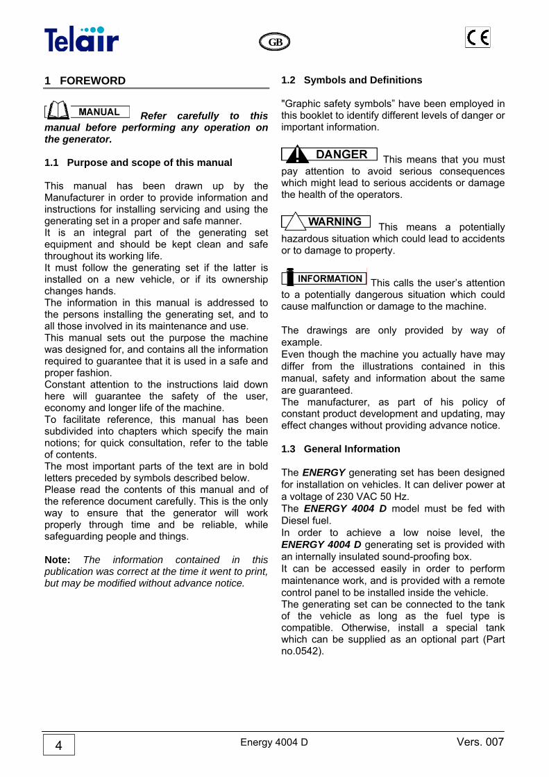
1 FOREWORD
Refer carefully to this manual before performing any operation on the generator. 1.1 Purpose and scope of this manual This manual has been drawn up by the Manufacturer in order to provide information and instructions for installing servicing and using the generating set in a proper and safe manner. It is an integral part of the generating set equipment and should be kept clean and safe throughout its working life. It must follow the generating set if the latter is installed on a new vehicle, or if its ownership changes hands. The information in this manual is addressed to the persons installing the generating set, and to all those involved in its maintenance and use. This manual sets out the purpose the machine was designed for, and contains all the information required to guarantee that it is used in a safe and proper fashion. Constant attention to the instructions laid down here will guarantee the safety of the user, economy and longer life of the machine. To facilitate reference, this manual has been subdivided into chapters which specify the main notions; for quick consultation, refer to the table of contents. The most important parts of the text are in bold letters preceded by symbols described below. Please read the contents of this manual and of the reference document carefully. This is the only way to ensure that the generator will work properly through time and be reliable, while safeguarding people and things. Note: The information contained in this publication was correct at the time it went to print, but may be modified without advance notice.
1.2 Symbols and Definitions "Graphic safety symbols” have been employed in this booklet to identify different levels of danger or important information.
This means that you must pay attention to avoid serious consequences which might lead to serious accidents or damage the health of the operators.
This means a potentially hazardous situation which could lead to accidents or to damage to property.
This calls the user’s attention to a potentially dangerous situation which could cause malfunction or damage to the machine. The drawings are only provided by way of example. Even though the machine you actually have may differ from the illustrations contained in this manual, safety and information about the same are guaranteed. The manufacturer, as part of his policy of constant product development and updating, may effect changes without providing advance notice. 1.3 General Information The ENERGY generating set has been designed for installation on vehicles. It can deliver power at a voltage of 230 VAC 50 Hz. The ENERGY 4004 D model must be fed with Diesel fuel. In order to achieve a low noise level, the ENERGY 4004 D generating set is provided with an internally insulated sound-proofing box. It can be accessed easily in order to perform maintenance work, and is provided with a remote control panel to be installed inside the vehicle. The generating set can be connected to the tank of the vehicle as long as the fuel type is compatible. Otherwise, install a special tank which can be supplied as an optional part (Part no.0542).
Vers. 007 Energy 4004 D
GB
5
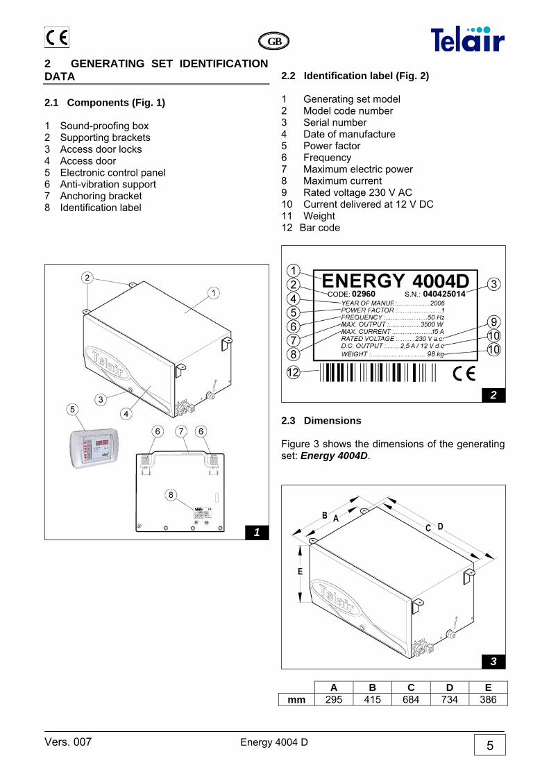
2 GENERATING SET IDENTIFICATION DATA 2.1 Components (Fig. 1) 1 Sound-proofing box 2 Supporting brackets 3 Access door locks 4 Access door 5 Electronic control panel 6 Anti-vibration support 7 Anchoring bracket 8 Identification label
2.2 Identification label (Fig. 2) 1 Generating set model 2 Model code number 3 Serial number 4 Date of manufacture 5 Power factor 6 Frequency 7 Maximum electric power 8 Maximum current 9 Rated voltage 230 V AC 10 Current delivered at 12 V DC 11 Weight 12 Bar code
2.3 Dimensions Figure 3 shows the dimensions of the generating set: Energy 4004D.
A B C D E
mm 295 415 684 734 386
2
1
3
Energy 4004 D Vers. 007
GB
6
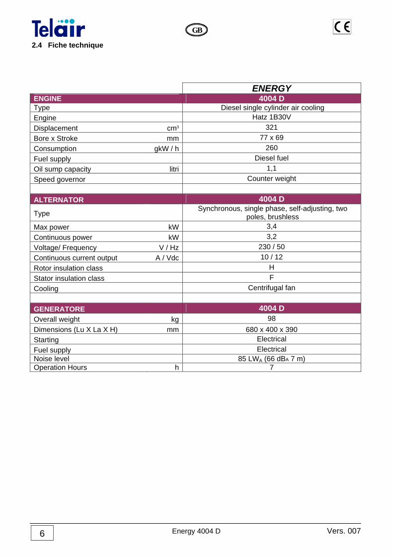
2.4 Fiche technique ENERGY ENGINE 4004 D Type Diesel single cylinder air cooling Engine Hatz 1B30V Displacement cm3 321 Bore x Stroke mm 77 x 69 Consumption gkW / h 260 Fuel supply Diesel fuel Oil sump capacity litri 1,1 Speed governor Counter weight ALTERNATOR 4004 D
Type Synchronous, single phase, self-adjusting, two
poles, brushless Max power kW 3,4 Continuous power kW 3,2 Voltage/ Frequency V / Hz 230 / 50 Continuous current output A / Vdc 10 / 12 Rotor insulation class H Stator insulation class F Cooling Centrifugal fan GENERATORE 4004 D Overall weight kg 98 Dimensions (Lu X La X H) mm 680 x 400 x 390 Starting Electrical Fuel supply Electrical Noise level 85 LWA (66 dBA 7 m) Operation Hours h 7
Vers. 007 Energy 4004 D
GB
7
3 SHIPPING, HANDLING, STORAGE 3.1 Storage The generating set is protected during shipping by suitable packaging. It must be stored horizontally, in a covered, dry and ventilated area.
Do not turn the package upside down. The right way up is the one shown by the symbol printed on the packaging ( ). 3.2 Weight Total weight including packing: ENERGY 4004 D 98 kg 3.3 Handling The generating set, complete with packaging, can be moved using common lifting and transport equipment. The boxes are provided with spacers in order to allow for the introduction of transpallet forks.
During lifting and transport, comply with accident prevention and safety regulations. Use lifting and transport equipment with a capacity greater than the load to be lifted.
4 INSTALLATION 4.1 Preliminary information
Before installing the generating set, it is essential to read these instructions, in order to avoid errors during installation.
The generator must be installed so as to prevent water seeping directly into the alternator through the inlet holes; it must therefore be protected. Improper installation of the generating sets can cause irreparable damage to the equipment and compromise the safety of the installation engineer, and invalidate guarrantee Should the generating sets be installed in a manner which does not comply with the instructions in this manual, the Manufacturer shall be held blameless for malfunctions or for the safety of the generating set, under D.M. 89/392/EEC. Furthermore, he shall be held blameless for any damage or injury to persons or things.
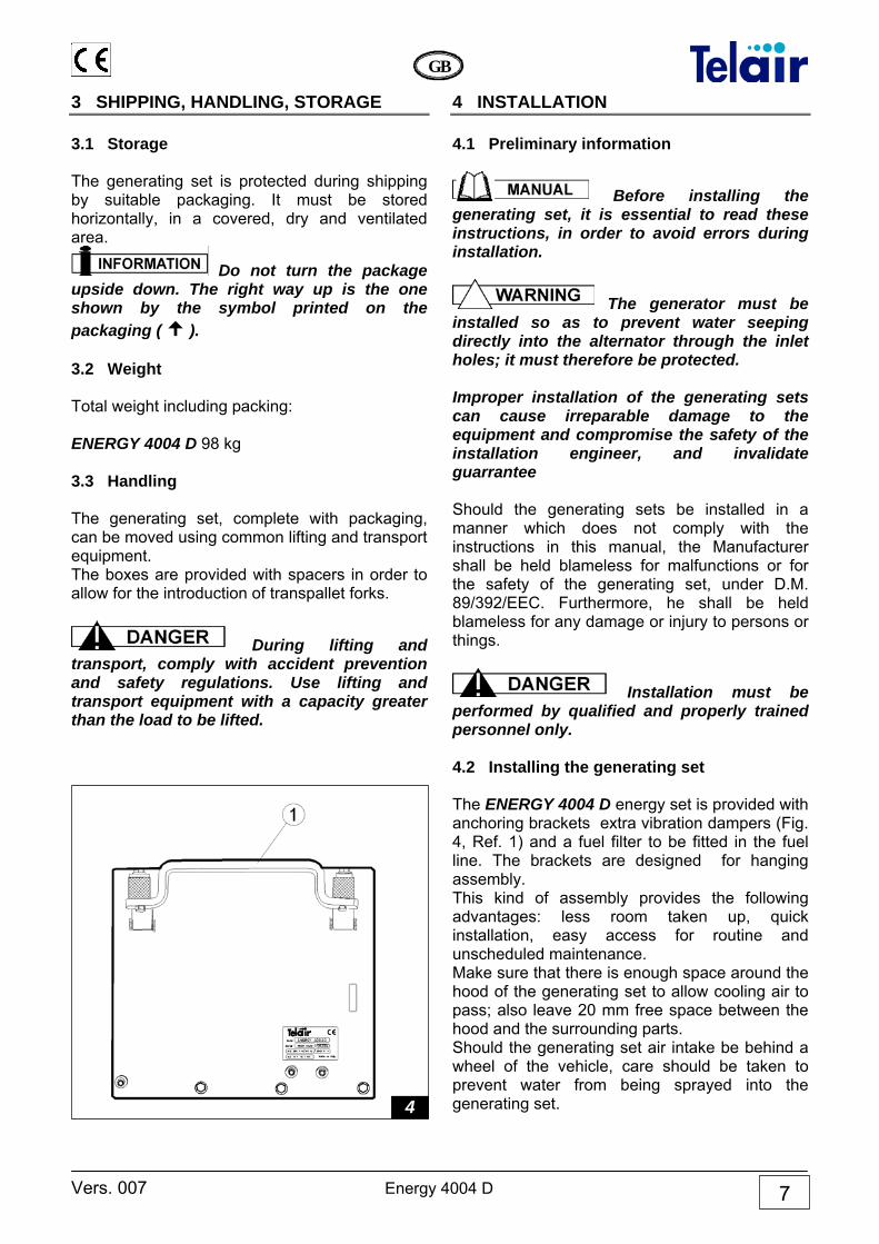
Installation must be performed by qualified and properly trained personnel only. 4.2 Installing the generating set The ENERGY 4004 D energy set is provided with anchoring brackets extra vibration dampers (Fig. 4, Ref. 1) and a fuel filter to be fitted in the fuel line. The brackets are designed for hanging assembly. This kind of assembly provides the following advantages: less room taken up, quick installation, easy access for routine and unscheduled maintenance. Make sure that there is enough space around the hood of the generating set to allow cooling air to pass; also leave 20 mm free space between the hood and the surrounding parts. Should the generating set air intake be behind a wheel of the vehicle, care should be taken to prevent water from being sprayed into the generating set.
4
Energy 4004 D Vers. 007
GB
8
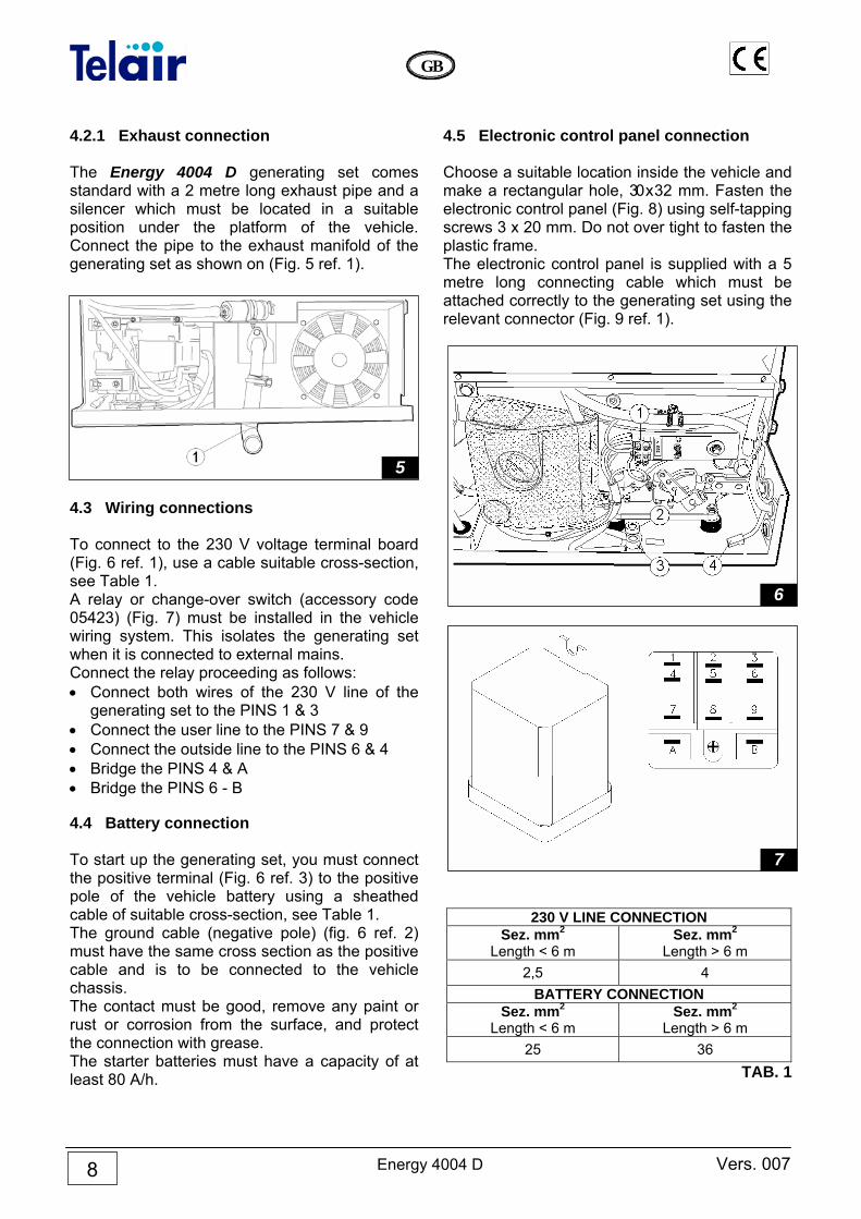
4.2.1 Exhaust connection The Energy 4004 D generating set comes standard with a 2 metre long exhaust pipe and a silencer which must be located in a suitable position under the platform of the vehicle. Connect the pipe to the exhaust manifold of the generating set as shown on (Fig. 5 ref. 1).
4.3 Wiring connections To connect to the 230 V voltage terminal board (Fig. 6 ref. 1), use a cable suitable cross-section, see Table 1. A relay or change-over switch (accessory code 05423) (Fig. 7) must be installed in the vehicle wiring system. This isolates the generating set when it is connected to external mains. Connect the relay proceeding as follows: • Connect both wires of the 230 V line of the
generating set to the PINS 1 & 3 • Connect the user line to the PINS 7 & 9 • Connect the outside line to the PINS 6 & 4 • Bridge the PINS 4 & A • Bridge the PINS 6 - B 4.4 Battery connection To start up the generating set, you must connect the positive terminal (Fig. 6 ref. 3) to the positive pole of the vehicle battery using a sheathed cable of suitable cross-section, see Table 1. The ground cable (negative pole) (fig. 6 ref. 2) must have the same cross section as the positive cable and is to be connected to the vehicle chassis. The contact must be good, remove any paint or rust or corrosion from the surface, and protect the connection with grease. The starter batteries must have a capacity of at least 80 A/h.
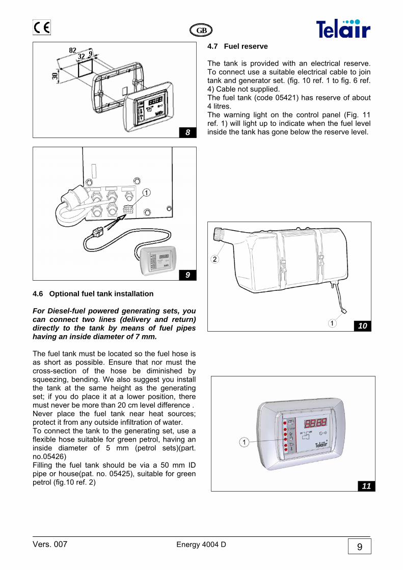
4.5 Electronic control panel connection Choose a suitable location inside the vehicle and make a rectangular hole, 30 x 32 mm. Fasten the electronic control panel (Fig. 8) using self-tapping screws 3 x 20 mm. Do not over tight to fasten the plastic frame. The electronic control panel is supplied with a 5 metre long connecting cable which must be attached correctly to the generating set using the relevant connector (Fig. 9 ref. 1).
230 V LINE CONNECTION Sez. mm2
Length < 6 m Sez. mm2
Length > 6 m 2,5 4
BATTERY CONNECTION Sez. mm2
Length < 6 m Sez. mm2
Length > 6 m 25 36
TAB. 1
7
6
5
Vers. 007 Energy 4004 D
GB
9
4.6 Optional fuel tank installation For Diesel-fuel powered generating sets, you can connect two lines (delivery and return) directly to the tank by means of fuel pipes having an inside diameter of 7 mm. The fuel tank must be located so the fuel hose is as short as possible. Ensure that nor must the cross-section of the hose be diminished by squeezing, bending. We also suggest you install the tank at the same height as the generating set; if you do place it at a lower position, there must never be more than 20 cm level difference . Never place the fuel tank near heat sources; protect it from any outside infiltration of water. To connect the tank to the generating set, use a flexible hose suitable for green petrol, having an inside diameter of 5 mm (petrol sets)(part. no.05426) Filling the fuel tank should be via a 50 mm ID pipe or house(pat. no. 05425), suitable for green petrol (fig.10 ref. 2)
4.7 Fuel reserve The tank is provided with an electrical reserve. To connect use a suitable electrical cable to join tank and generator set. (fig. 10 ref. 1 to fig. 6 ref. 4) Cable not supplied. The fuel tank (code 05421) has reserve of about 4 litres. The warning light on the control panel (Fig. 11 ref. 1) will light up to indicate when the fuel level inside the tank has gone below the reserve level.
9
8
10
11
Energy 4004 D Vers. 007
GB
10
5 OPERATING INSTRUCTIONS The ENERGY range of generating sets consist of endothermic Diesel motors connected to an alternator able to produce alternating and continuous electric power. The generating sets are assembled inside a steel casing, insulated and sound-proofed using special sound absorbing materials. The fuel is fed to the endothermic motor by a pump assembled in the generating set. 5.1 Machine safety The generating sets come with sealed casings, so there is no danger of contact with any rotating parts, high temperatures or live cables. The door is secured with lock and key. Keys must not be left within the reach of children or unauthorized persons.
The generating sets must be used only and exclusively with their doors shut. Remove any flammable substance from near the generating set, for example: petrol, paint, solvents, etc. Never fill up the fuel tank while the generator is running. Never touch the generating sets or the wiring connections with wet hands. Never replace the fuses or the thermal switches using others having a higher amperage. Should you have to check any electrical part, this must be done only with the motor turned off and by specialised personnel. The generating sets were made in compliance with the safety standards listed in the statement of compliance.
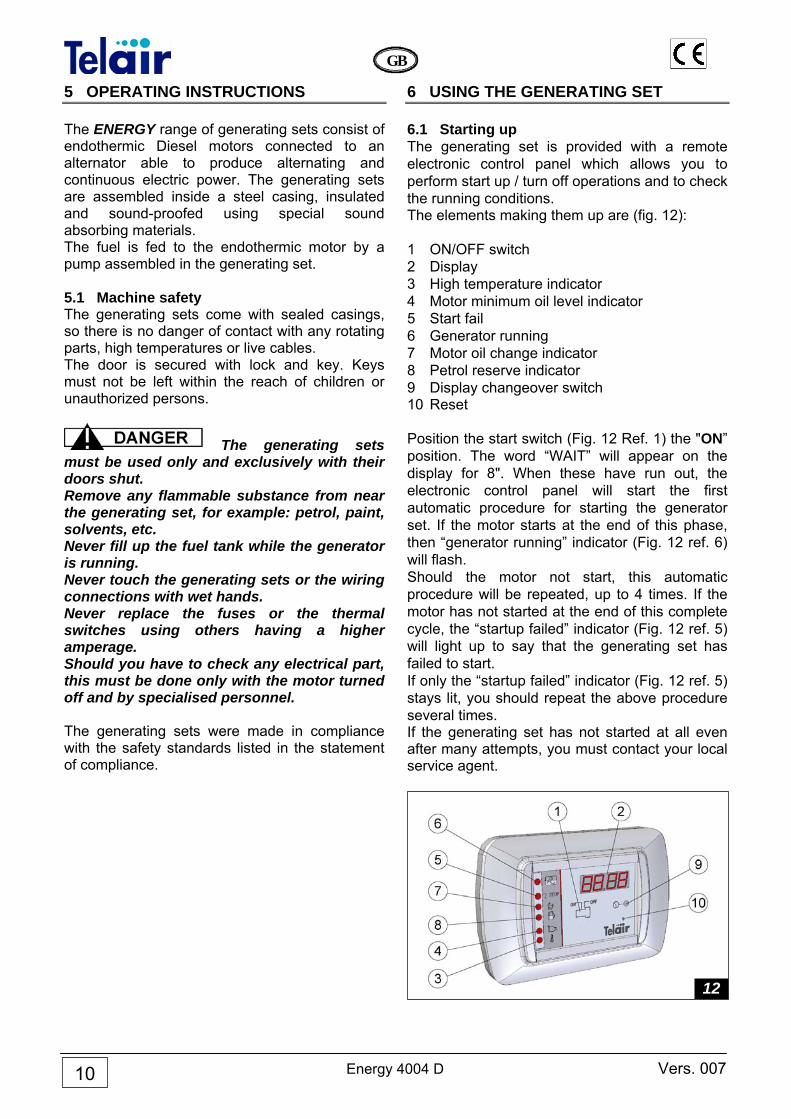
6 USING THE GENERATING SET 6.1 Starting up The generating set is provided with a remote electronic control panel which allows you to perform start up / turn off operations and to check the running conditions. The elements making them up are (fig. 12): 1 ON/OFF switch 2 Display 3 High temperature indicator 4 Motor minimum oil level indicator 5 Start fail 6 Generator running 7 Motor oil change indicator 8 Petrol reserve indicator 9 Display changeover switch 10 Reset Position the start switch (Fig. 12 Ref. 1) the "ON” position. The word “WAIT” will appear on the display for 8". When these have run out, the electronic control panel will start the first automatic procedure for starting the generator set. If the motor starts at the end of this phase, then “generator running” indicator (Fig. 12 ref. 6) will flash. Should the motor not start, this automatic procedure will be repeated, up to 4 times. If the motor has not started at the end of this complete cycle, the “startup failed” indicator (Fig. 12 ref. 5) will light up to say that the generating set has failed to start. If only the “startup failed” indicator (Fig. 12 ref. 5) stays lit, you should repeat the above procedure several times. If the generating set has not started at all even after many attempts, you must contact your local service agent.
12
Vers. 007 Energy 4004 D
GB
11
6.2 Turning off the generating set To stop the generating set, place the “ON/OFF” switch in its OFF position (Fig. 12 ref. 1)
The generating set has an internal combustion engine; therefore the fuel used is highly flammable. The exhaust gases are conveyed under the casing; their temperature, inevitably, is quite high, even though they are mixed with cooling air. Do not touch the casing near the exhaust, and do not put your hands or other objects inside the casing. 6.3 Forbidden use
The generating set must be installed and used only by qualified personnel, authorised according to the manufacturer’s instructions. The generating set must be used only and exclusively to produce electrical power on vehicles provided with an electrical system made according to standards and depending on the quantity of power delivered. 6.4 Advice To make the best use of the generating set, remember that even small overloads - if they last for some time - will make the temperature cut-off contact open (Fig. 13 ref. 1). During the running-in period, do not subject the new motor to a load higher than 70% of the rated load, at least for the first 50 running hours.
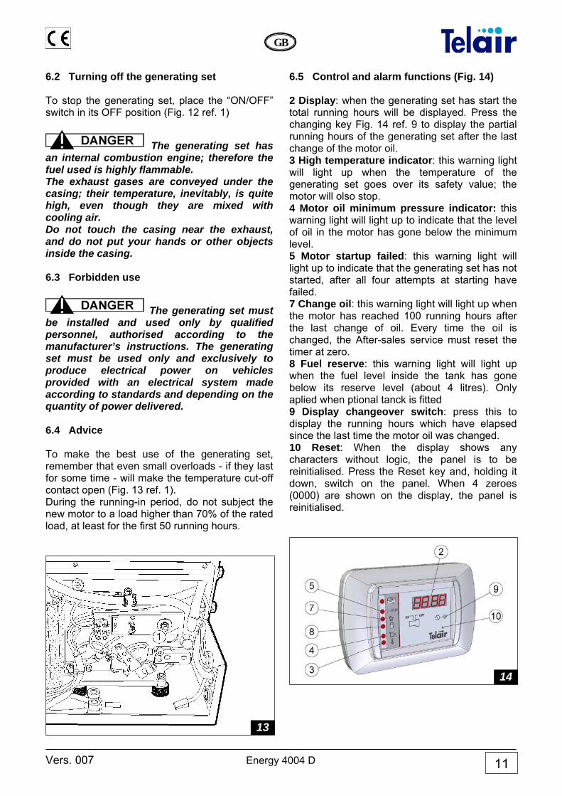
6.5 Control and alarm functions (Fig. 14) 2 Display: when the generating set has start the total running hours will be displayed. Press the changing key Fig. 14 ref. 9 to display the partial running hours of the generating set after the last change of the motor oil. 3 High temperature indicator: this warning light will light up when the temperature of the generating set goes over its safety value; the motor will olso stop. 4 Motor oil minimum pressure indicator: this warning light will light up to indicate that the level of oil in the motor has gone below the minimum level. 5 Motor startup failed: this warning light will light up to indicate that the generating set has not started, after all four attempts at starting have failed. 7 Change oil: this warning light will light up when the motor has reached 100 running hours after the last change of oil. Every time the oil is changed, the After-sales service must reset the timer at zero. 8 Fuel reserve: this warning light will light up when the fuel level inside the tank has gone below its reserve level (about 4 litres). Only aplied when ptional tanck is fitted 9 Display changeover switch: press this to display the running hours which have elapsed since the last time the motor oil was changed. 10 Reset: When the display shows any characters without logic, the panel is to be reinitialised. Press the Reset key and, holding it down, switch on the panel. When 4 zeroes (0000) are shown on the display, the panel is reinitialised.
14
13
Energy 4004 D Vers. 007
GB
12
7 MAINTENANCE INSTRUCTIONS
Use only original spare parts. The use of spare parts of non-equivalent quality may damage the generating set. Routine control and adjustments are of the essence in preserving a high level of performance. Routine maintenance also ensures long life of the generating set. 7.1 Maintenance list See table at the bottom of the page. 7.2 Non specialist maintanance To perform this kind of operation, it will be necessary to open the door of the generating set. The following precautions must therefore be taken: 1) The generating set must not be running, and
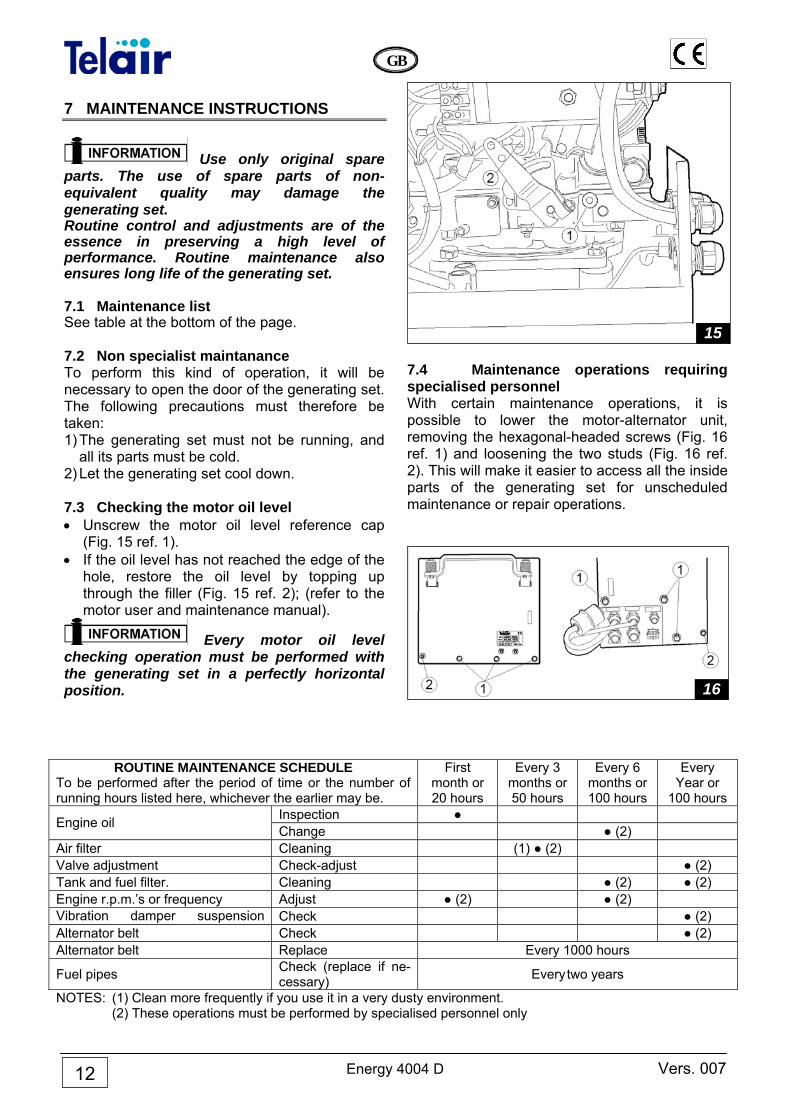
all its parts must be cold. 2) Let the generating set cool down. 7.3 Checking the motor oil level • Unscrew the motor oil level reference cap
(Fig. 15 ref. 1). • If the oil level has not reached the edge of the
hole, restore the oil level by topping up through the filler (Fig. 15 ref. 2); (refer to the motor user and maintenance manual).
Every motor oil level checking operation must be performed with the generating set in a perfectly horizontal position.
7.4 Maintenance operations requiring specialised personnel With certain maintenance operations, it is possible to lower the motor-alternator unit, removing the hexagonal-headed screws (Fig. 16 ref. 1) and loosening the two studs (Fig. 16 ref. 2). This will make it easier to access all the inside parts of the generating set for unscheduled maintenance or repair operations.
16
15
ROUTINE MAINTENANCE SCHEDULE To be performed after the period of time or the number of running hours listed here, whichever the earlier may be.
First month or 20 hours
Every 3 months or 50 hours
Every 6 months or 100 hours
Every Year or
100 hours Inspection ● Engine oil Change ● (2)
Air filter Cleaning (1) ● (2) Valve adjustment Check-adjust ● (2) Tank and fuel filter. Cleaning ● (2) ● (2) Engine r.p.m.’s or frequency Adjust ● (2) ● (2) Vibration damper suspension Check ● (2) Alternator belt Check ● (2) Alternator belt Replace Every 1000 hours
Fuel pipes Check (replace if ne-cessary) Every two years
NOTES: (1) Clean more frequently if you use it in a very dusty environment. (2) These operations must be performed by specialised personnel only
Vers. 007 Energy 4004 D
GB
13
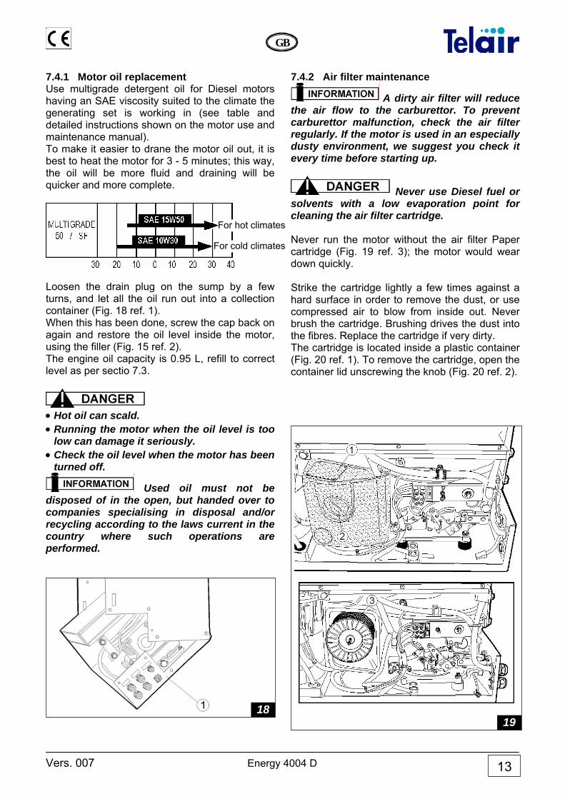
7.4.1 Motor oil replacement Use multigrade detergent oil for Diesel motors having an SAE viscosity suited to the climate the generating set is working in (see table and detailed instructions shown on the motor use and maintenance manual). To make it easier to drane the motor oil out, it is best to heat the motor for 3 - 5 minutes; this way, the oil will be more fluid and draining will be quicker and more complete.
Loosen the drain plug on the sump by a few turns, and let all the oil run out into a collection container (Fig. 18 ref. 1). When this has been done, screw the cap back on again and restore the oil level inside the motor, using the filler (Fig. 15 ref. 2). The engine oil capacity is 0.95 L, refill to correct level as per sectio 7.3.
• Hot oil can scald. • Running the motor when the oil level is too
low can damage it seriously. • Check the oil level when the motor has been
turned off.
Used oil must not be disposed of in the open, but handed over to companies specialising in disposal and/or recycling according to the laws current in the country where such operations are performed.
7.4.2 Air filter maintenance
A dirty air filter will reduce the air flow to the carburettor. To prevent carburettor malfunction, check the air filter regularly. If the motor is used in an especially dusty environment, we suggest you check it every time before starting up.
Never use Diesel fuel or solvents with a low evaporation point for cleaning the air filter cartridge. Never run the motor without the air filter Paper cartridge (Fig. 19 ref. 3); the motor would wear down quickly. Strike the cartridge lightly a few times against a hard surface in order to remove the dust, or use compressed air to blow from inside out. Never brush the cartridge. Brushing drives the dust into the fibres. Replace the cartridge if very dirty. The cartridge is located inside a plastic container (Fig. 20 ref. 1). To remove the cartridge, open the container lid unscrewing the knob (Fig. 20 ref. 2).
1819
For cold climates
For hot climates
Energy 4004 D Vers. 007
GB
14
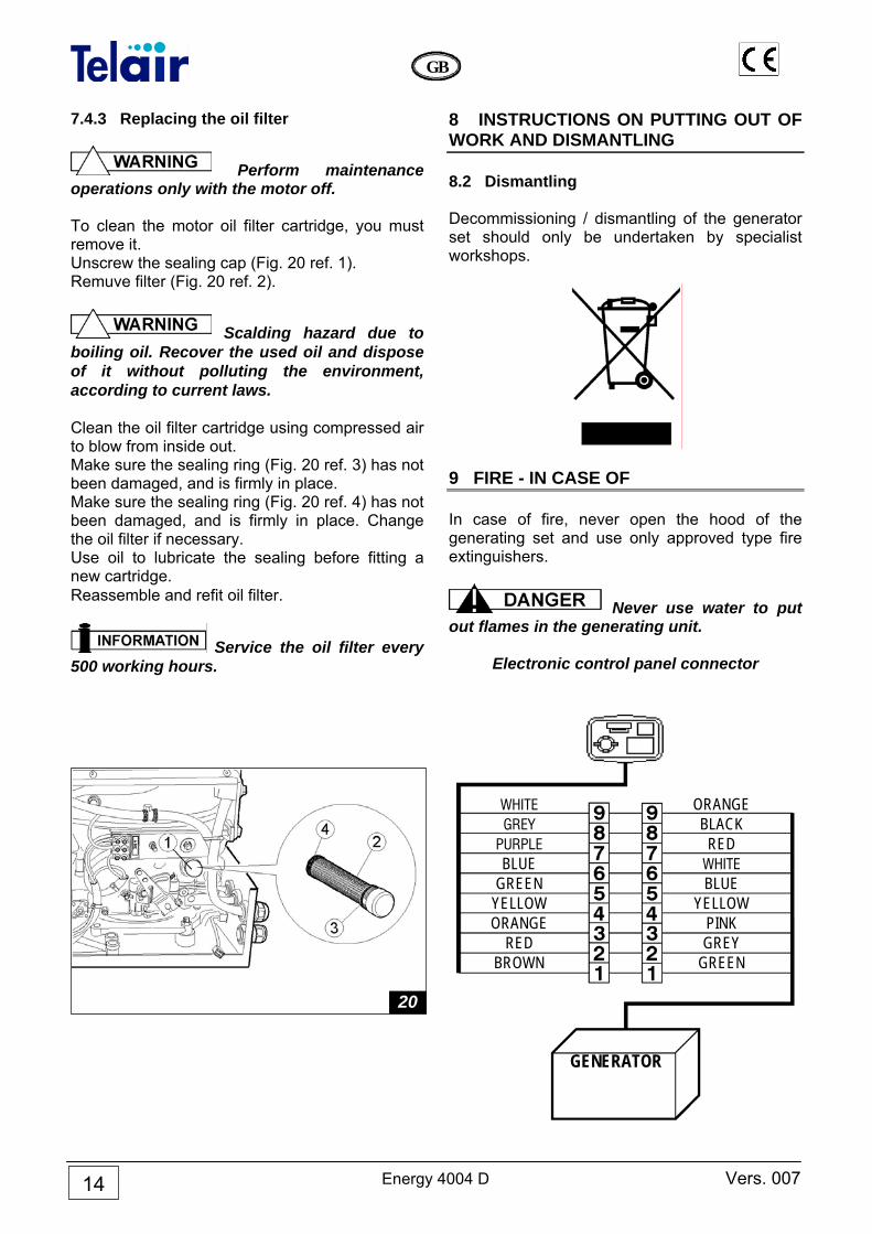
7.4.3 Replacing the oil filter
Perform maintenance operations only with the motor off. To clean the motor oil filter cartridge, you must remove it. Unscrew the sealing cap (Fig. 20 ref. 1). Remuve filter (Fig. 20 ref. 2).
Scalding hazard due to boiling oil. Recover the used oil and dispose of it without polluting the environment, according to current laws. Clean the oil filter cartridge using compressed air to blow from inside out. Make sure the sealing ring (Fig. 20 ref. 3) has not been damaged, and is firmly in place. Make sure the sealing ring (Fig. 20 ref. 4) has not been damaged, and is firmly in place. Change the oil filter if necessary. Use oil to lubricate the sealing before fitting a new cartridge. Reassemble and refit oil filter.
Service the oil filter every 500 working hours.
8 INSTRUCTIONS ON PUTTING OUT OF WORK AND DISMANTLING 8.2 Dismantling Decommissioning / dismantling of the generator set should only be undertaken by specialist workshops.
9 FIRE - IN CASE OF In case of fire, never open the hood of the generating set and use only approved type fire extinguishers.
Never use water to put out flames in the generating unit.
Electronic control panel connector
WHITE ORANGE GREY BLACK PURPLE RED BLUE WHITE GREEN BLUE YELLOW YELLOW ORANGE PINK RED GREY BROWN GREEN GENERATOR
20
Vers. 007 Energy 4004 D
GB
15
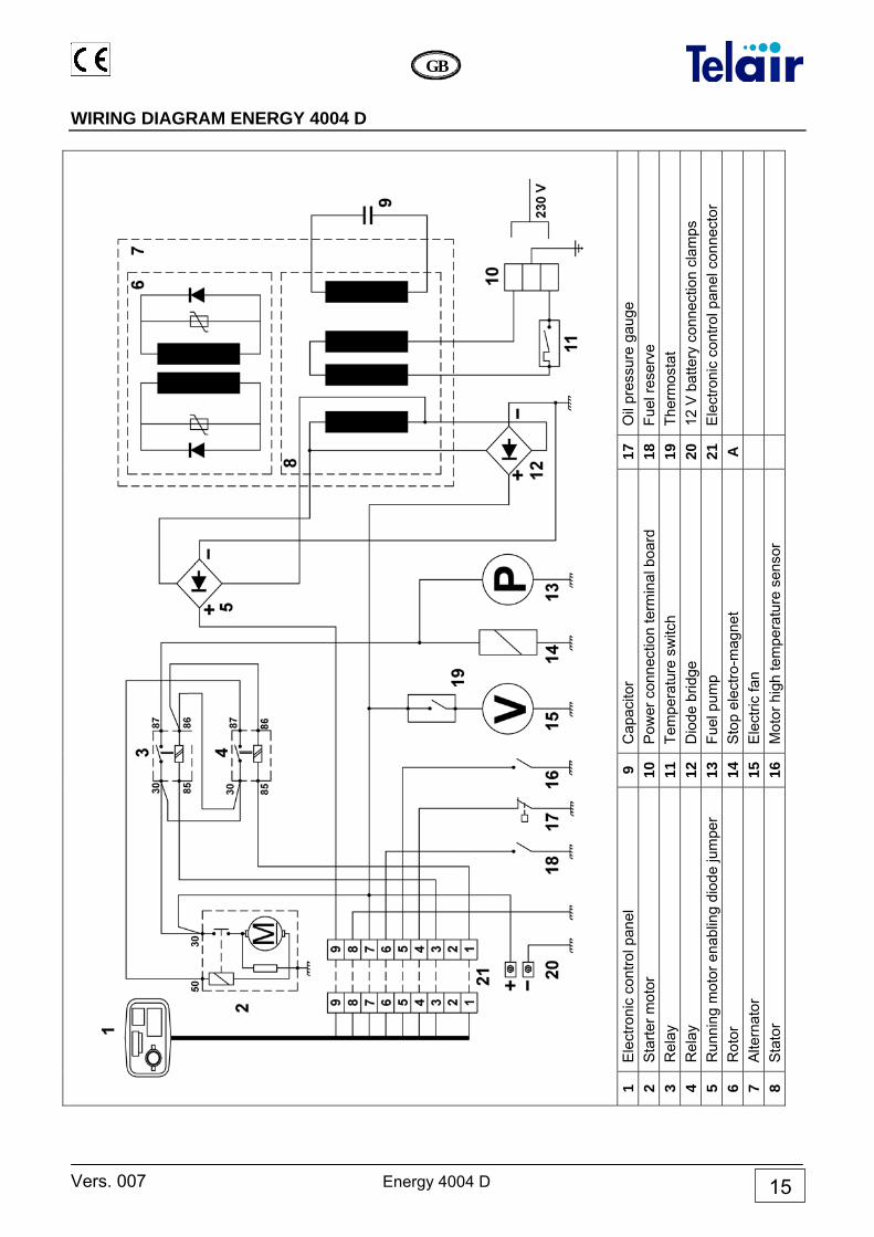
WIRING DIAGRAM ENERGY 4004 D
Oil
pres
sure
gau
ge
Fuel
rese
rve
Ther
mos
tat
12 V
bat
tery
con
nect
ion
clam
ps
Ele
ctro
nic
cont
rol p
anel
con
nect
or
17
18
19
20
21
A
Cap
acito
r P
ower
con
nect
ion
term
inal
boa
rd
Tem
pera
ture
sw
itch
Dio
de b
ridge
Fu
el p
ump
Sto
p el
ectro
-mag
net
Ele
ctric
fan
Mot
or h
igh
tem
pera
ture
sen
sor
9 10
11
12
13
14
15
16
1Ele
ctro
nic
cont
rol p
anel
S
tarte
r mot
or
Rel
ay
Rel
ay
Run
ning
mot
or e
nabl
ing
diod
e ju
mpe
r R
otor
A
ltern
ator
S
tato
r
1 2 3 4 5 6 7 8
Energy 4004 D Vers. 007
GB
16
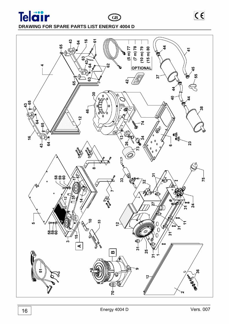
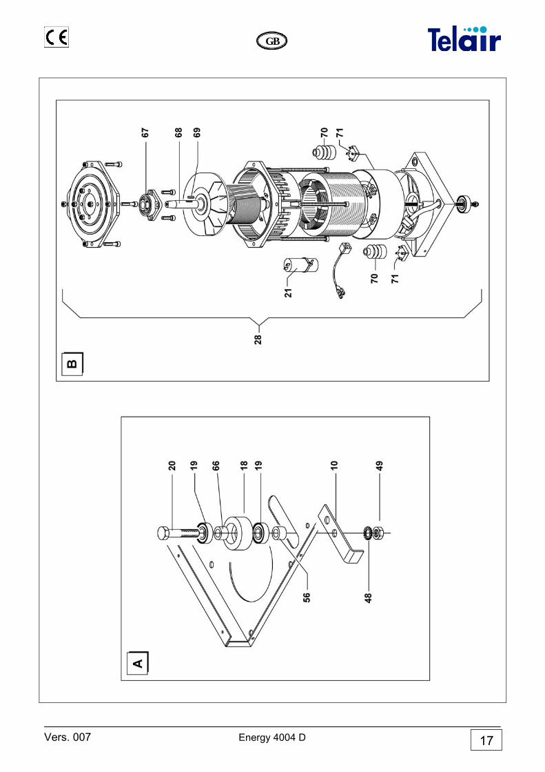
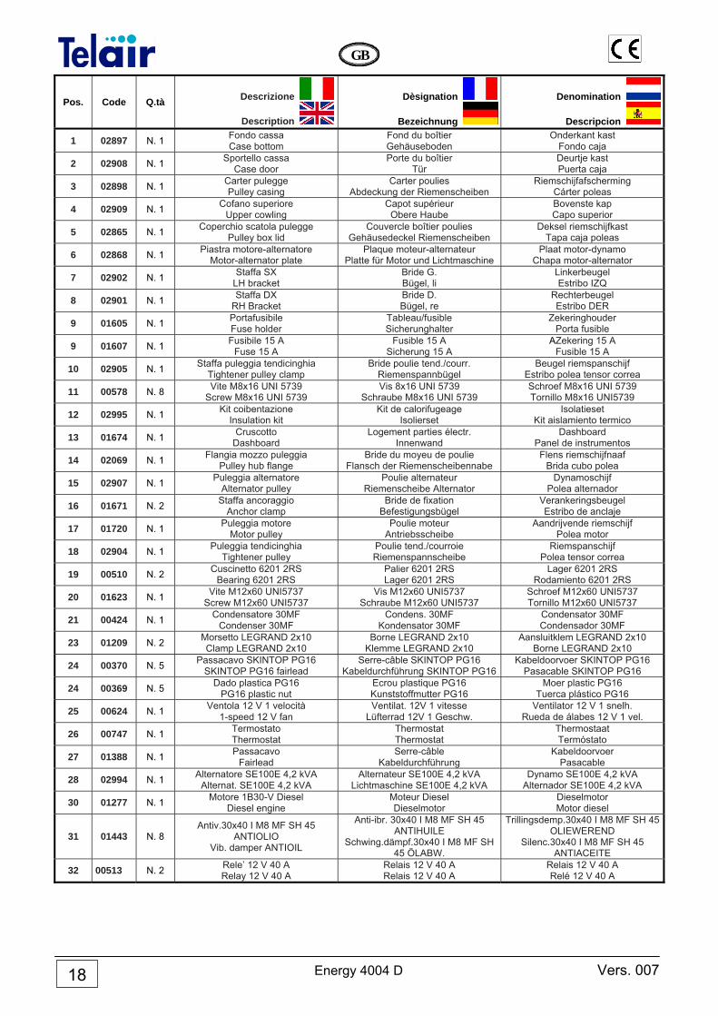
DRAWING FOR SPARE PARTS LIST ENERGY 4004 D
Vers. 007 Energy 4004 D
GB
17
Energy 4004 D Vers. 007
GB
18
Pos. Code Q.tà Descrizione
Description
Dèsignation
Bezeichnung
Denomination
Descripcion
1 02897 N. 1 Fondo cassa Case bottom
Fond du boîtier Gehäuseboden
Onderkant kast Fondo caja
2 02908 N. 1 Sportello cassa Case door
Porte du boîtier Tür
Deurtje kast Puerta caja
3 02898 N. 1 Carter pulegge Pulley casing
Carter poulies Abdeckung der Riemenscheiben
Riemschijfafscherming Cárter poleas
4 02909 N. 1 Cofano superiore Upper cowling
Capot supérieur Obere Haube
Bovenste kap Capo superior
5 02865 N. 1 Coperchio scatola pulegge Pulley box lid
Couvercle boîtier poulies Gehäusedeckel Riemenscheiben
Deksel riemschijfkast Tapa caja poleas
6 02868 N. 1 Piastra motore-alternatore Motor-alternator plate
Plaque moteur-alternateur Platte für Motor und Lichtmaschine
Plaat motor-dynamo Chapa motor-alternator
7 02902 N. 1 Staffa SX LH bracket
Bride G. Bügel, li
Linkerbeugel Estribo IZQ
8 02901 N. 1 Staffa DX RH Bracket
Bride D. Bügel, re
Rechterbeugel Estribo DER
9 01605 N. 1 Portafusibile Fuse holder
Tableau/fusible Sicherunghalter
Zekeringhouder Porta fusible
9 01607 N. 1 Fusibile 15 A Fuse 15 A
Fusible 15 A Sicherung 15 A
AZekering 15 A Fusible 15 A
10 02905 N. 1 Staffa puleggia tendicinghia Tightener pulley clamp
Bride poulie tend./courr. Riemenspannbügel
Beugel riemspanschijf Estribo polea tensor correa
11 00578 N. 8 Vite M8x16 UNI 5739 Screw M8x16 UNI 5739
Vis 8x16 UNI 5739 Schraube M8x16 UNI 5739
Schroef M8x16 UNI 5739 Tornillo M8x16 UNI5739
12 02995 N. 1 Kit coibentazione Insulation kit
Kit de calorifugeage Isolierset
Isolatieset Kit aislamiento termico
13 01674 N. 1 Cruscotto Dashboard
Logement parties électr. Innenwand
Dashboard Panel de instrumentos
14 02069 N. 1 Flangia mozzo puleggia Pulley hub flange
Bride du moyeu de poulie Flansch der Riemenscheibennabe
Flens riemschijfnaaf Brida cubo polea
15 02907 N. 1 Puleggia alternatore Alternator pulley
Poulie alternateur Riemenscheibe Alternator
Dynamoschijf Polea alternador
16 01671 N. 2 Staffa ancoraggio Anchor clamp
Bride de fixation Befestigungsbügel
Verankeringsbeugel Estribo de anclaje
17 01720 N. 1 Puleggia motore Motor pulley
Poulie moteur Antriebsscheibe
Aandrijvende riemschijf Polea motor
18 02904 N. 1 Puleggia tendicinghia Tightener pulley
Poulie tend./courroie Riemenspannscheibe
Riemspanschijf Polea tensor correa
19 00510 N. 2 Cuscinetto 6201 2RS Bearing 6201 2RS
Palier 6201 2RS Lager 6201 2RS
Lager 6201 2RS Rodamiento 6201 2RS
20 01623 N. 1 Vite M12x60 UNI5737 Screw M12x60 UNI5737
Vis M12x60 UNI5737 Schraube M12x60 UNI5737
Schroef M12x60 UNI5737 Tornillo M12x60 UNI5737
21 00424 N. 1 Condensatore 30MF Condenser 30MF
Condens. 30MF Kondensator 30MF
Condensator 30MF Condensador 30MF
23 01209 N. 2 Morsetto LEGRAND 2x10 Clamp LEGRAND 2x10
Borne LEGRAND 2x10 Klemme LEGRAND 2x10
Aansluitklem LEGRAND 2x10 Borne LEGRAND 2x10
24 00370 N. 5 Passacavo SKINTOP PG16 SKINTOP PG16 fairlead
Serre-câble SKINTOP PG16 Kabeldurchführung SKINTOP PG16
Kabeldoorvoer SKINTOP PG16 Pasacable SKINTOP PG16
24 00369 N. 5 Dado plastica PG16 PG16 plastic nut
Ecrou plastique PG16 Kunststoffmutter PG16
Moer plastic PG16 Tuerca plástico PG16
25 00624 N. 1 Ventola 12 V 1 velocità 1-speed 12 V fan
Ventilat. 12V 1 vitesse Lüfterrad 12V 1 Geschw.
Ventilator 12 V 1 snelh. Rueda de álabes 12 V 1 vel.
26 00747 N. 1 Termostato Thermostat
Thermostat Thermostat
Thermostaat Termóstato
27 01388 N. 1 Passacavo Fairlead
Serre-câble Kabeldurchführung
Kabeldoorvoer Pasacable
28 02994 N. 1 Alternatore SE100E 4,2 kVA Alternat. SE100E 4,2 kVA
Alternateur SE100E 4,2 kVA Lichtmaschine SE100E 4,2 kVA
Dynamo SE100E 4,2 kVA Alternador SE100E 4,2 kVA
30 01277 N. 1 Motore 1B30-V Diesel Diesel engine
Moteur Diesel Dieselmotor
Dieselmotor Motor diesel
31 01443 N. 8 Antiv.30x40 I M8 MF SH 45
ANTIOLIO Vib. damper ANTIOIL
Anti-ibr. 30x40 I M8 MF SH 45 ANTIHUILE
Schwing.dämpf.30x40 I M8 MF SH 45 ÖLABW.
Trillingsdemp.30x40 I M8 MF SH 45OLIEWEREND
Silenc.30x40 I M8 MF SH 45 ANTIACEITE
32 00513 N. 2 Rele’ 12 V 40 A Relay 12 V 40 A
Relais 12 V 40 A Relais 12 V 40 A
Relais 12 V 40 A Relé 12 V 40 A
Vers. 007 Energy 4004 D
GB
19
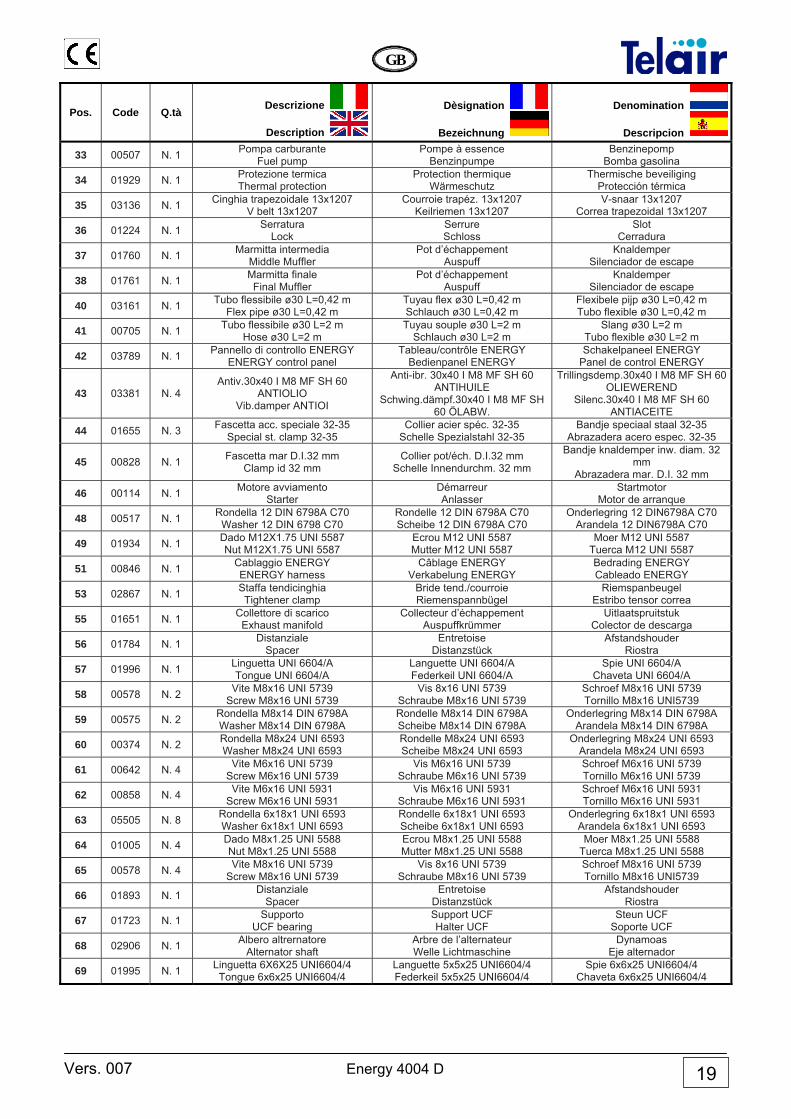
Pos. Code Q.tà Descrizione
Description
Dèsignation
Bezeichnung
Denomination
Descripcion
33 00507 N. 1 Pompa carburante Fuel pump
Pompe à essence Benzinpumpe
Benzinepomp Bomba gasolina
34 01929 N. 1 Protezione termica Thermal protection
Protection thermique Wärmeschutz
Thermische beveiliging Protección térmica
35 03136 N. 1 Cinghia trapezoidale 13x1207 V belt 13x1207
Courroie trapéz. 13x1207 Keilriemen 13x1207
V-snaar 13x1207 Correa trapezoidal 13x1207
36 01224 N. 1 Serratura Lock
Serrure Schloss
Slot Cerradura
37 01760 N. 1 Marmitta intermedia Middle Muffler
Pot d’échappement Auspuff
Knaldemper Silenciador de escape
38 01761 N. 1 Marmitta finale Final Muffler
Pot d’échappement Auspuff
Knaldemper Silenciador de escape
40 03161 N. 1 Tubo flessibile ø30 L=0,42 m Flex pipe ø30 L=0,42 m
Tuyau flex ø30 L=0,42 m Schlauch ø30 L=0,42 m
Flexibele pijp ø30 L=0,42 m Tubo flexible ø30 L=0,42 m
41 00705 N. 1 Tubo flessibile ø30 L=2 m Hose ø30 L=2 m
Tuyau souple ø30 L=2 m Schlauch ø30 L=2 m
Slang ø30 L=2 m Tubo flexible ø30 L=2 m
42 03789 N. 1 Pannello di controllo ENERGY ENERGY control panel
Tableau/contrôle ENERGY Bedienpanel ENERGY
Schakelpaneel ENERGY Panel de control ENERGY
43 03381 N. 4 Antiv.30x40 I M8 MF SH 60
ANTIOLIO Vib.damper ANTIOI
Anti-ibr. 30x40 I M8 MF SH 60 ANTIHUILE
Schwing.dämpf.30x40 I M8 MF SH 60 ÖLABW.
Trillingsdemp.30x40 I M8 MF SH 60 OLIEWEREND
Silenc.30x40 I M8 MF SH 60 ANTIACEITE
44 01655 N. 3 Fascetta acc. speciale 32-35 Special st. clamp 32-35
Collier acier spéc. 32-35 Schelle Spezialstahl 32-35
Bandje speciaal staal 32-35 Abrazadera acero espec. 32-35
45 00828 N. 1 Fascetta mar D.I.32 mm Clamp id 32 mm
Collier pot/éch. D.I.32 mm Schelle Innendurchm. 32 mm
Bandje knaldemper inw. diam. 32 mm
Abrazadera mar. D.I. 32 mm
46 00114 N. 1 Motore avviamento Starter
Démarreur Anlasser
Startmotor Motor de arranque
48 00517 N. 1 Rondella 12 DIN 6798A C70 Washer 12 DIN 6798 C70
Rondelle 12 DIN 6798A C70 Scheibe 12 DIN 6798A C70
Onderlegring 12 DIN6798A C70 Arandela 12 DIN6798A C70
49 01934 N. 1 Dado M12X1.75 UNI 5587 Nut M12X1.75 UNI 5587
Ecrou M12 UNI 5587 Mutter M12 UNI 5587
Moer M12 UNI 5587 Tuerca M12 UNI 5587
51 00846 N. 1 Cablaggio ENERGY ENERGY harness
Câblage ENERGY Verkabelung ENERGY
Bedrading ENERGY Cableado ENERGY
53 02867 N. 1 Staffa tendicinghia Tightener clamp
Bride tend./courroie Riemenspannbügel
Riemspanbeugel Estribo tensor correa
55 01651 N. 1 Collettore di scarico Exhaust manifold
Collecteur d’échappement Auspuffkrümmer
Uitlaatspruitstuk Colector de descarga
56 01784 N. 1 Distanziale Spacer
Entretoise Distanzstück
Afstandshouder Riostra
57 01996 N. 1 Linguetta UNI 6604/A Tongue UNI 6604/A
Languette UNI 6604/A Federkeil UNI 6604/A
Spie UNI 6604/A Chaveta UNI 6604/A
58 00578 N. 2 Vite M8x16 UNI 5739 Screw M8x16 UNI 5739
Vis 8x16 UNI 5739 Schraube M8x16 UNI 5739
Schroef M8x16 UNI 5739 Tornillo M8x16 UNI5739
59 00575 N. 2 Rondella M8x14 DIN 6798A Washer M8x14 DIN 6798A
Rondelle M8x14 DIN 6798A Scheibe M8x14 DIN 6798A
Onderlegring M8x14 DIN 6798A Arandela M8x14 DIN 6798A
60 00374 N. 2 Rondella M8x24 UNI 6593 Washer M8x24 UNI 6593
Rondelle M8x24 UNI 6593 Scheibe M8x24 UNI 6593
Onderlegring M8x24 UNI 6593 Arandela M8x24 UNI 6593
61 00642 N. 4 Vite M6x16 UNI 5739 Screw M6x16 UNI 5739
Vis M6x16 UNI 5739 Schraube M6x16 UNI 5739
Schroef M6x16 UNI 5739 Tornillo M6x16 UNI 5739
62 00858 N. 4 Vite M6x16 UNI 5931 Screw M6x16 UNI 5931
Vis M6x16 UNI 5931 Schraube M6x16 UNI 5931
Schroef M6x16 UNI 5931 Tornillo M6x16 UNI 5931
63 05505 N. 8 Rondella 6x18x1 UNI 6593 Washer 6x18x1 UNI 6593
Rondelle 6x18x1 UNI 6593 Scheibe 6x18x1 UNI 6593
Onderlegring 6x18x1 UNI 6593 Arandela 6x18x1 UNI 6593
64 01005 N. 4 Dado M8x1.25 UNI 5588 Nut M8x1.25 UNI 5588
Ecrou M8x1.25 UNI 5588 Mutter M8x1.25 UNI 5588
Moer M8x1.25 UNI 5588 Tuerca M8x1.25 UNI 5588
65 00578 N. 4 Vite M8x16 UNI 5739 Screw M8x16 UNI 5739
Vis 8x16 UNI 5739 Schraube M8x16 UNI 5739
Schroef M8x16 UNI 5739 Tornillo M8x16 UNI5739
66 01893 N. 1 Distanziale Spacer
Entretoise Distanzstück
Afstandshouder Riostra
67 01723 N. 1 Supporto UCF bearing
Support UCF Halter UCF
Steun UCF Soporte UCF
68 02906 N. 1 Albero altrernatore Alternator shaft
Arbre de l’alternateur Welle Lichtmaschine
Dynamoas Eje alternador
69 01995 N. 1 Linguetta 6X6X25 UNI6604/4 Tongue 6x6x25 UNI6604/4
Languette 5x5x25 UNI6604/4 Federkeil 5x5x25 UNI6604/4
Spie 6x6x25 UNI6604/4 Chaveta 6x6x25 UNI6604/4
Energy 4004 D Vers. 007
GB
20
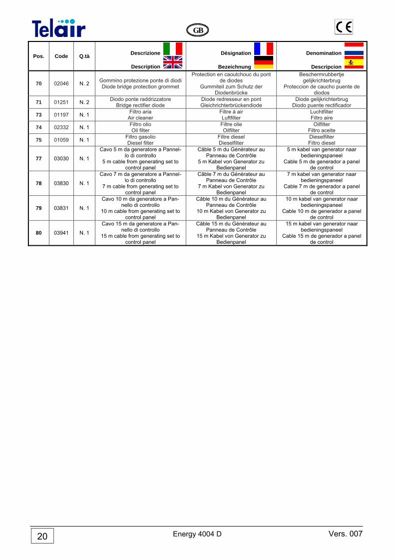
Pos. Code Q.tà Descrizione
Description
Dèsignation
Bezeichnung
Denomination
Descripcion
70 02046 N. 2 Gommino protezione ponte di diodi Diode bridge protection grommet
Protection en caoutchouc du pont de diodes
Gummiteil zum Schutz der Diodenbrücke
Beschermrubbertje gelijkrichterbrug
Proteccion de caucho puente de diodos
71 01251 N. 2 Diodo ponte raddrizzatore Bridge rectifier diode
Diode redresseur en pont Gleichrichterbrückendiode
Diode gelijkrichterbrug Diodo puente rectificador
73 01197 N. 1 Filtro aria Air cleaner
Filtre à air Luftfilter
Luchtfilter Filtro aire
74 02332 N. 1 Filtro olio Oil filter
Filtre olie Oilfilter
Oilfilter Filtro aceite
75 01059 N. 1 Filtro gasolio Diesel filter
Filtre diesel Dieselfilter
Dieselfilter Filtro diesel
77 03030 N. 1
Cavo 5 m da generatore a Pannel-lo di controllo
5 m cable from generating set to control panel
Câble 5 m du Générateur au Panneau de Contrôle
5 m Kabel von Generator zu Bedienpanel
5 m kabel van generator naar bedieningspaneel
Cable 5 m de generador a panel de control
78 03830 N. 1
Cavo 7 m da generatore a Pannel-lo di controllo
7 m cable from generating set to control panel
Câble 7 m du Générateur au Panneau de Contrôle
7 m Kabel von Generator zu Bedienpanel
7 m kabel van generator naar bedieningspaneel
Cable 7 m de generador a panel de control
79 03831 N. 1
Cavo 10 m da generatore a Pan-nello di controllo
10 m cable from generating set to control panel
Câble 10 m du Générateur au Panneau de Contrôle
10 m Kabel von Generator zu Bedienpanel
10 m kabel van generator naar bedieningspaneel
Cable 10 m de generador a panel de control
80 03941 N. 1
Cavo 15 m da generatore a Pan-nello di controllo
15 m cable from generating set to control panel
Câble 15 m du Générateur au Panneau de Contrôle
15 m Kabel von Generator zu Bedienpanel
15 m kabel van generator naar bedieningspaneel
Cable 15 m de generador a panel de control
Vers. 007 Energy 4004 D
GB
21
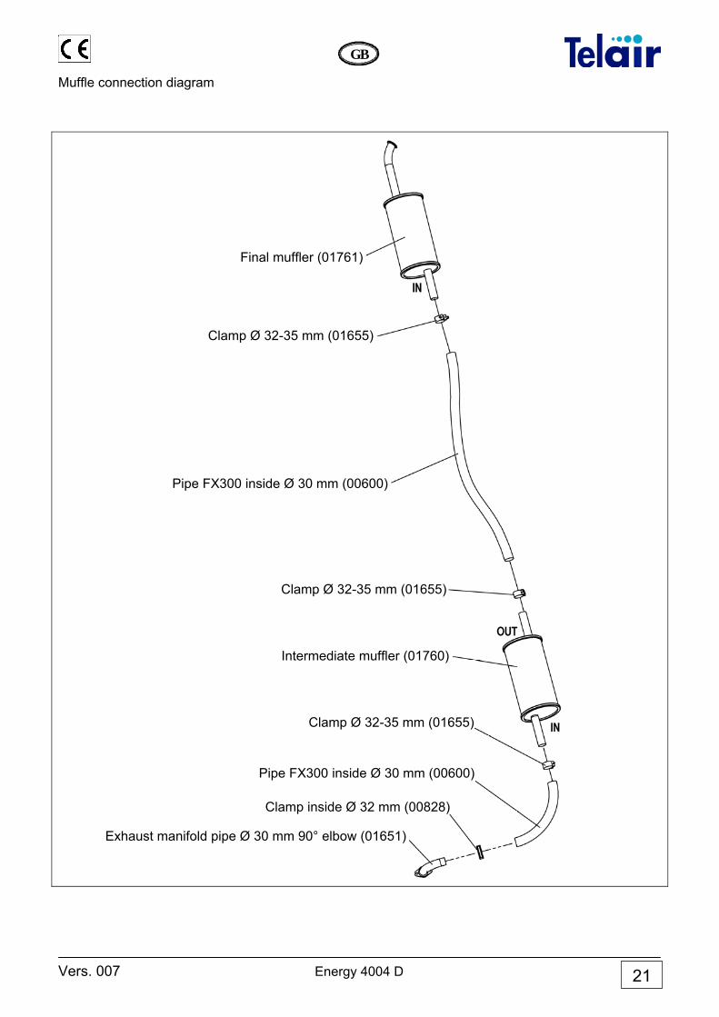
Muffle connection diagram
Clamp Ø 32-35 mm (01655)
Final muffler (01761)
Pipe FX300 inside Ø 30 mm (00600)
Clamp Ø 32-35 mm (01655)
Intermediate muffler (01760)
Clamp Ø 32-35 mm (01655)
Pipe FX300 inside Ø 30 mm (00600)
Clamp inside Ø 32 mm (00828)
Exhaust manifold pipe Ø 30 mm 90° elbow (01651)
Energy 4004 D Vers. 007
GB
22
GENERAL WARRANTY TERMS
TELAIR guarantees its products against any material and/or manufacturing faults and defects. The entitlement to warranty cover for new engines is valid for a period of 24 months from the time of handing over to the end user, or for a maximum of 2000 operating hours, whichever of these limits is reached first. In all cases the warranty period shall lapse no later than 26 months (28 months if delivered outside Europe) after delivery ex factory. For electric and hydraulic components, pipes, belts, sealing elements, injection nozzles, clutches, gear boxes, the warranty term is 12 months from the time of handing over to the end user, or for a maximum of 2000 operating hours, whichever of these limits is reached first. In all cases the warranty period shall lapse no later than 14 months (16 months if delivered outside Europe) after delivery ex factory. In any case, the costs of lubricants and consumables shall be charged. Any transport expenses shall be intended as to be covered by the purchaser; the same applies to any expenses connected with inspections requested by the customer and accepted by TELAIR. In any case, the costs of lubricants and consumables shall be charged. The manufacturer’s warranty shall only be valid if: • the customer has carried out any routine maintenance according to the
recommended schedule and has promptly visited the nearest after-sale centre if required.
• the customer can produce a document showing the date of sale (invoice or receipt).
Such document will have to be kept with care and be intact when produced to the TELAIR After-Sales centre on requesting service.
In any case, the purchaser shall not be entitled to: • terminate the contract; • claim damages to persons or property; • ask that the warranty be extended in the event of product defects or
malfunctioning.
Vers. 007 Energy 4004 D
GB
23
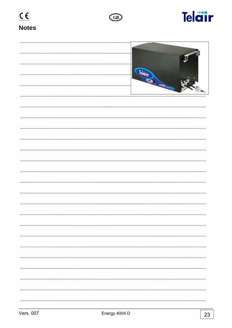
Notes
...............................................................................................................................................................
...............................................................................................................................................................
...............................................................................................................................................................
...............................................................................................................................................................
...............................................................................................................................................................
...............................................................................................................................................................
...............................................................................................................................................................
...............................................................................................................................................................
...............................................................................................................................................................
...............................................................................................................................................................
...............................................................................................................................................................
...............................................................................................................................................................
...............................................................................................................................................................
...............................................................................................................................................................
...............................................................................................................................................................
...............................................................................................................................................................
...............................................................................................................................................................
...............................................................................................................................................................
...............................................................................................................................................................
...............................................................................................................................................................
...............................................................................................................................................................
...............................................................................................................................................................
...............................................................................................................................................................
...............................................................................................................................................................
...............................................................................................................................................................
ITALY Via E.Majorana 49 48022 LUGO( RA ) Tel. + 39 0545 25037 Fax.+ 39 0545 32064 E-mail: [email protected] www.telecogroup.com ZIMMER TECHNIK FŐR MOBILE FREIZEIT Raiffeisenstr, 6 64347 Griesheim Tel. 06155 797873 - Fax. 06155 797871 [email protected]
IN EUROPE: GREAT BRITAIN - SCAN TERIEUR LTD 30, The Metro Centre, Tolpits Lane - Watford, Herts - England - WD18 9XG Tel. 01923 800353 - Fax 01923 220358 HOLLAND / BELGIUM - KARMAN TRADING Lagewed 54 – 3849 PE Hierden – the Netherlands Tel. 0341 722450 - Fax 0341 722451 e-mail: [email protected] web site: www.karmantrading.nl FRANCE - BLEYS JEAN-PHILIPPE 19, Rue de la Parcheminerie 18700 Aubigny sur Nere - France Tel.02 48580367 – Fax 02 48583585 e-mail: [email protected] Service Technique France : 06 83 31 44 05 ESPAÑA - NAUCCA CARAVANING, S.A. Poligono Industrial CAN ROQUETA 2 – Calle Can Lletget,2 08202 Sabadell (Barcelona) - España Tel. 00 34 937 457 054 - Fax. 00 34 937 254 484 e-mail: [email protected] ÖSTERREICH – TELECO GmbH 82041 Deisenhofen - Deutshland Tel. 0049 8031 98939 - Fax. 0049 8031 98949 e-mail: [email protected] www.telecogroup.com IN DEUTSHLAND TELECO GmbH 82041 Deisenhofen - Tel. 0049 8031 98939 - Fax. 0049 8031 98949 e-mail: [email protected] www.telecogroup.com
Service für Teleco Anlagen in Deutschland:
09001000690
Service für Teleco Anlagen in Österreich:
0900949470
Foto e disegni non contrattuali - Les photos et les dessins ne sont donnés qu’à titre indicatif. We reserve the right to make technical changes without prior notice - Fotos und Zeichnungen nicht vertraglich.
Foto’s en tekeningen niet contractueel - Fotos y planos no indicados en contrato


![DSP 4x4 - Manual (Print) 4x4 - Manual [Online] - Rev 2.pdf · 1 DSP 4x4 Owner’s Manual September 2013 OUTPUT 1 OUTPUT 2 OUTPUT 3 OUTPUT 4 INPUT 1 INPUT 2 INPUT 3 INPUT 4](https://static.documents.pub/doc/80x56/5c55002893f3c317c5105481/dsp-4x4-manual-print-4x4-manual-online-rev-2pdf-1-dsp-4x4-owners.jpg)


