
NEW HAMPSHIRE CODE OF ADMINISTRATIVE RULES
i Env-Wq 700
TABLE OF CONTENTS
CHAPTER Env-Wq 700 STANDARDS OF DESIGN AND CONSTRUCTION FOR SEWERAGE AND WASTEWATER TREATMENT FACILITIES
PART Env-Wq 701 PURPOSE AND APPLICABILITY
Env-Wq 701.01 Purpose Env-Wq 701.02 Applicability
PART Env-Wq 702 DEFINITIONS Env-Wq 702.01 Annual Average Design Flow Env-Wq 702.02 Beneficial Use Env-Wq 702.03 Biochemical Oxygen Demand (BOD5) Env-Wq 702.04 Clean Water Act (CWA) Env-Wq 702.05 Collector Sewer Env-Wq 702.06 Cross-country Locations Env-Wq 702.07 Department Env-Wq 702.08 Discharge Permit Env-Wq 702.09 Engineer Env-Wq 702.10 HS-20 Loading Env-Wq 702.11 Industrial Waste Env-Wq 702.12 Interceptor Sewer Env-Wq 702.13 Local Legislative Body Env-Wq 702.14 Maximum Daily Flow Env-Wq 702.15 Maximum Monthly Flow Env-Wq 702.16 Minimum Daily Flow Env-Wq 702.17 Minimum Monthly Flow Env-Wq 702.18 Municipality Env-Wq 702.19 National Electric Code (NEC) Env-Wq 702.20 Owner Env-Wq 702.21 Peak Instantaneous Flow Env-Wq 702.22 Peak Hourly Flow Env-Wq 702.23 Person Env-Wq 702.24 Pressure Sewer Env-Wq 702.25 Privately Owned Env-Wq 702.26 Roadway Locations Env-Wq 702.27 Sewage Env-Wq 702.28 Sewer Env-Wq 702.29 Sewer Appurtenances Env-Wq 702.30 Sewerage Env-Wq 702.31 Standard Scale Env-Wq 702.32 Standard Dimension Ratio (SDR) Env-Wq 702.33 Total Suspended Solids (TSS) Env-Wq 702.34 Wastewater Treatment Plant (WWTP)
PART Env-Wq 703 ENGINEERING DESIGN DOCUMENTS Env-Wq 703.01 Submittal of Design Drawings, Technical Specifications, and Supporting Documentation Env-Wq 703.02 Technical Specifications and Supporting Documentation Env-Wq 703.03 Design Drawings Env-Wq 703.04 Design Drawings for Sewerage Env-Wq 703.05 Design Drawings for Sewage Pumping Stations Env-Wq 703.06 WWTP Plans Env-Wq 703.07 Sewer Connection Permit Env-Wq 703.08 Project Revision and Approval Requirements Env-Wq 703.09 Contract and Bidding Requirements
NEW HAMPSHIRE CODE OF ADMINISTRATIVE RULES
ii Env-Wq 700
PART Env-Wq 704 DESIGN OF SEWERAGE Env-Wq 704.01 Type of Sewerage Env-Wq 704.02 Design Period Env-Wq 704.03 Design Flow Basis Env-Wq 704.04 Details of Design and Construction of Gravity Sewers Env-Wq 704.05 Gravity Sewer Construction Materials Env-Wq 704.06 Gravity Sewer Pipe Testing Env-Wq 704.07 Details of Design and Construction of Force Mains and Pressure Sewers Env-Wq 704.08 Force Main and Pressure Sewer Construction Materials Env-Wq 704.09 Force Main and Pressure Sewer Testing Env-Wq 704.10 Grinder Pumps for Pressure Sewers Env-Wq 704.11 Trench Construction Env-Wq 704.12 Manholes: General Construction Requirements Env-Wq 704.13 Manholes: Materials of Construction Env-Wq 704.14 Manholes: Steps Env-Wq 704.15 Manholes: Placement Env-Wq 704.16 Manholes: Drop Entry Construction Requirements Env-Wq 704.17 Manholes: Testing Env-Wq 704.18 Inverted Siphons Env-Wq 704.19 Protection of Water Supplies Env-Wq 704.20 Service Connections
PART Env-Wq 705 SEWAGE PUMPING STATIONS Env-Wq 705.01 Sewage Pumping Station Design Requirements: Flooding and Weather Protection Env-Wq 705.02 Sewage Pumping Station Design Requirements: Wet Well and Dry Well Construction Env-Wq 705.03 Sewage Pumping Station Design Requirements: Allowable Pump Types, Pump Controls
and Pump Size Env-Wq 705.04 Sewage Pumping Station Design Requirements: Pump Station Access Env-Wq 705.05 Sewage Pumping Station Design Requirements: Flow and Pump Usage Measurement Env-Wq 705.06 Sewage Pumping Station Design Requirements: Potable Water Restrictions and Protection Env-Wq 705.07 Sewage Pumping Station Electrical Requirements Env-Wq 705.08 Sewage Pumping Station Ventilation Requirements Env-Wq 705.09 Sewage Pumping Station Alarm Systems Env-Wq 705.10 Sewage Pumping Station Operation and Maintenance Manual Env-Wq 705.11 Sewage Pumping Station Emergency Operation
PART Env-Wq 706 SITING OF WWTPs Env-Wq 706.01 WWTP Location Env-Wq 706.02 Buffer Distances Env-Wq 706.03 Flooding Env-Wq 706.04 Effluent Quality
PART Env-Wq 707 BASIS OF DESIGN REPORTS FOR WWTPs Env-Wq 707.01 Basis of WWTP Design Env-Wq 707.02 Basis of Design Report: Project Planning Env-Wq 707.03 Basis of Design Report: Existing Facilities Env-Wq 707.04 Basis of Design Report: Project Need Env-Wq 707.05 Basis of Design Report: Treatment Technology Options Considered Env-Wq 707.06 Basis of Design Report: Life Cycle Comparison of Treatment Technology Options Env-Wq 707.07 Basis of Design Report: Proposed Project – Recommended Treatment Technology Env-Wq 707.08 Meetings Required
NEW HAMPSHIRE CODE OF ADMINISTRATIVE RULES
iii Env-Wq 700
PART Env-Wq 708 ADDITIONAL WWTP REQUIREMENTS Env-Wq 708.01 Installation and Initial Operation Env-Wq 708.02 Required Redundancy Env-Wq 708.03 Planning for Unit Process Maintenance and Dewatering Required Env-Wq 708.04 Piping and Flow Distribution Devices Env-Wq 708.05 WWTP Design and Layout Env-Wq 708.06 Design and Layout of Chemical Feed Equipment: Storage Requirements Env-Wq 708.07 Design and Layout of Chemical Feed Equipment: Feed Requirements Env-Wq 708.08 Operation and Maintenance Manuals Env-Wq 708.09 Site Access Env-Wq 708.10 Site Grading Env-Wq 708.11 Outside Lighting Env-Wq 708.12 Floor Slope Env-Wq 708.13 Access to Equipment Env-Wq 708.14 Essential Power Requirements for WWTPs Env-Wq 708.15 Instrumentation and Control Requirements Env-Wq 708.16 Essential Water Supply Requirements for WWTPs Env-Wq 708.17 Wastewater Flow Measurement Env-Wq 708.18 Sampling Env-Wq 708.19 WWTP Outfalls Env-Wq 708.20 Safety Env-Wq 708.21 Hazardous Chemical Handling Env-Wq 708.22 Laboratory Equipment Env-Wq 708.23 WWTP Alarms Env-Wq 708.24 Testing Env-Wq 708.25 Septage Receiving Stations
PART Env-Wq 709 INFLUENT HEADWORKS Env-Wq 709.01 Screening Devices: Location, Operation, and Maintenance Env-Wq 709.02 Screening Devices: Design and Capacity Env-Wq 709.03 Grit Removal Facilities Env-Wq 709.04 Grinding Facilities
PART Env-Wq 710 FLOW AND WASTE STRENGTH EQUALIZATION Env-Wq 710.01 Flow and Waste Strength Variations Env-Wq 710.02 Equalization Tank: Location and Size Env-Wq 710.03 Equalization Tank: Aeration and Mixing Env-Wq 710.04 Equalization Tank: Controls and Drainage
PART Env-Wq 711 SETTLING Env-Wq 711.01 Primary Settling Tanks Env-Wq 711.02 Secondary Settling Tanks: Number and Types of Units Env-Wq 711.03 Secondary Settling Tanks: Design Criteria for Solids Loading Env-Wq 711.04 Secondary Settling Tanks: Design Criteria for Overflow Rates Env-Wq 711.05 Secondary Settling Tanks: Design Criteria for Inlets and Outlets Env-Wq 711.06 Secondary Settling Tanks: Design Criteria for Sludge and Scum Removal Env-Wq 711.07 Secondary Settling Tanks: Design Criteria for Return Sludge Env-Wq 711.08 Secondary Settling Tanks: Design Criteria for Waste Sludge
PART Env-Wq 712 CHEMICAL COAGULATION FOR PRIMARY AND SECONDARY SETTLING Env-Wq 712.01 Chemical Coagulation: Application and Mixing Env-Wq 712.02 Chemical Coagulation: Flocculation Tanks Env-Wq 712.03 Chemical Coagulation: Process Impacts
NEW HAMPSHIRE CODE OF ADMINISTRATIVE RULES
iv Env-Wq 700
PART Env-Wq 713 SUSPENDED GROWTH BIOLOGICAL TREATMENT Env-Wq 713.01 Activated Sludge: General Design Requirements Env-Wq 713.02 Activated Sludge: Aeration System Requirements Env-Wq 713.03 Activated Sludge: Aeration System Performance Requirements Env-Wq 713.04 Activated Sludge: Protection of Aeration Systems Env-Wq 713.05 Activated Sludge: Aeration Tank Design Env-Wq 713.06 Oxidation Ditches Env-Wq 713.07 Sequencing Batch Reactors Env-Wq 713.08 Aerated Lagoon Design: General Requirements Env-Wq 713.09 Aerated Lagoon Design: Aeration Equipment Env-Wq 713.10 Aerated Lagoon Design: Inlet and Outlet Piping Env-Wq 713.11 Aerated Lagoon Design: Distribution and Interconnection Piping Env-Wq 713.12 Aerated Lagoon Design: Overflow Structures Env-Wq 713.13 Aerated Lagoon Design: Embankments, Dikes & Bottom Env-Wq 713.14 Aerated Lagoon Design: Groundwater Pollution and Soil Formation Env-Wq 713.15 Aerated Lagoon Design: Area Control
PART Env-Wq 714 FIXED FILM BIOLOGICAL TREATMENT Env-Wq 714.01 Trickling Filters: General Requirements Env-Wq 714.02 Trickling Filters: Size Requirements Env-Wq 714.03 Rotating Biological Contactors (RBCs)
PART Env-Wq 715 DISINFECTION Env-Wq 715.01 Disinfection Requirement Env-Wq 715.02 Methods Env-Wq 715.03 Hypochlorite Systems Env-Wq 715.04 Dechlorination Systems Env-Wq 715.05 Ultraviolet (UV) Irradiation Systems
PART Env-Wq 716 SLUDGE HANDLING AND DISPOSAL Env-Wq 716.01 Sludge Stabilization Methods Env-Wq 716.02 Sludge Stabilization Design Requirements Env-Wq 716.03 Sludge Handling and Disposal Design Criteria Env-Wq 716.04 Sludge Grinder Pumps Env-Wq 716.05 Sludge Storage Requirements Env-Wq 716.06 Anaerobic Sludge Digestion: Tanks Env-Wq 716.07 Anaerobic Sludge Digestion: Piping and Appurtenances Env-Wq 716.08 Aerobic Sludge Digestion Env-Wq 716.09 Gravity Sludge Thickening Env-Wq 716.10 Mechanical Sludge Thickening Env-Wq 716.11 Sludge Pumps and Piping Env-Wq 716.12 Sludge Conditioning Env-Wq 716.13 Mechanical Sludge Dewatering Env-Wq 716.14 Sludge Drying Beds Env-Wq 716.15 Additional Required Features of Sludge Handling Processes
PART Env-Wq 717 INNOVATIVE AND ALTERNATIVE TECHNOLOGIES Env-Wq 717.01 Purpose and Applicability Env-Wq 717.02 Operating Requirements Env-Wq 717.03 Use of I/A Technology Env-Wq 717.04 I/A Technology Pilot Requirements Env-Wq 717.05 I/A Technology Evaluation Process Env-Wq 717.06 Technology Assessment Report Submittal and Review Env-Wq 717.07 Basis of Design
NEW HAMPSHIRE CODE OF ADMINISTRATIVE RULES
v Env-Wq 700
Env-Wq 717.08 Final Design Env-Wq 717.09 Performance Assessment Env-Wq 717.10 Extension of Performance Assessment Period
PART Env-Wq 718 OWNERSHIP OF WWTPs Env-Wq 718.01 Purpose Env-Wq 718.02 Subsurface Disposal Options Env-Wq 718.03 Ownership Requirements Env-Wq 718.04 Capacity Env-Wq 718.05 Technical Documentation Requirements Env-Wq 718.06 Financial Documentation Requirements
PART Env-Wq 719 WAIVERS Env-Wq 719.01 Purpose Env-Wq 719.02 Waiver Requests Env-Wq 719.03 Decisions on Waiver Requests
NEW HAMPSHIRE CODE OF ADMINISTRATIVE RULES
1 Env-Wq 700
CHAPTER Env-Wq 700 STANDARDS OF DESIGN AND CONSTRUCTION FOR SEWERAGE AND WASTEWATER TREATMENT FACILITIES
Statutory Authority: RSA 485-A:6, III
REVISION NOTE:
Document #8590, effective 3-25-06, readopted with amendments and redesignated former Chapter Env-Ws 700 titled Standards of Design and Construction for Sewerage and Wastewater Treatment Facilities as Env-Wq 700 pursuant to a rules reorganization plan for Department rules approved by the Director of the Office of Legislative Services on 9-7-05.
The prior filings for former Env-Ws 700 include the following documents:
#757, eff 2-18-76
#2245, eff 12-31-82
#2670, eff 4-12-84
#4860, eff 7-5-90; EXPIRED 7-5-96
#6350, INTERIM, eff 10-5-96, EXPIRED 2-2-97
#6590, eff 9-26-97
#8434, INTERIM, eff 9-26-05, EXPIRES: 3-25-06
PART Env-Wq 701 PURPOSE AND APPLICABILITY
Env-Wq 701.01 Purpose. The purpose of this chapter is to protect public health and the environment by establishing minimum technical standards and requirements for the planning, design, and construction of sewerage and wastewater treatment facilities, including solids handling and disposal facilities.
Source. (See Revision Note at chapter heading for Env-Wq 700) #8590, eff 3-25-06; ss by #10693, eff 10-15-14
Env-Wq 701.02 Applicability.
(a) Env-Wq 700 shall apply to any person that designs or constructs new sewerage, wastewater treatment, or solids handling and disposal facilities or any appurtenances related thereto.
(b) For purposes of proposed upgrades or other modifications to existing sewerage, wastewater treatment, or solids handling and disposal facilities or any appurtenances related thereto, the following provisions shall apply:
(1) Env-Wq 702 relative to definitions;
(2) Env-Wq 703 relative to engineering design documents; and
(3) All provisions of Env-Wq 704 through Env-Wq 719 that directly apply to the system(s) proposed to be upgraded or modified.
Source. (See Revision Note at chapter heading for Env-Wq 700) #8590, eff 3-25-06; ss by #10693, eff 10-15-14
PART Env-Wq 702 DEFINITIONS
Env-Wq 702.01 “Annual average design flow” means the entire volume of flow, including all infiltration and inflow (I/I), discharged in one year, expressed as a daily rate.
Source. (See Revision Note at chapter heading for Env-Wq 700) #8590, eff 3-25-06; ss by #10693, eff 10-15-14
NEW HAMPSHIRE CODE OF ADMINISTRATIVE RULES
2 Env-Wq 700
Env-Wq 702.02 “Beneficial use” means “beneficial use” as defined in Env-Wq 802.
Source. (See Revision Note at chapter heading for Env-Wq 700) #8590, eff 3-25-06; ss by #10693, eff 10-15-14
Env-Wq 702.03 “Biochemical oxygen demand (BOD5)” means the amount of oxygen used by microorganisms in the biochemical oxidation of decomposable organic matter under aerobic conditions over a 5-day period, as expressed in milligrams per liter (mg/L).
Source. (See Revision Note at chapter heading for Env-Wq 700) #8590, eff 3-25-06; ss by #10693, eff 10-15-14
Env-Wq 702.04 “Clean Water Act (CWA)” means the Federal Clean Water Act, Pub. L. 92-500 as amended by Pub. L. 95-217, Pub. L. 95-576, Pub. L. 96-483, Pub. L. 97-117, Pub. L. 100-4, 33 U.S.C. 1251 et seq.
Source. (See Revision Note at chapter heading for Env-Wq 700) #8590, eff 3-25-06; ss by #10693, eff 10-15-14
Env-Wq 702.05 “Collector sewer” means a sewer that serves the primary purpose of collecting and transporting wastewater to the interceptor sewers.
Source. (See Revision Note at chapter heading for Env-Wq 700) #8590, eff 3-25-06; ss by #10693, eff 10-15-14
Env-Wq 702.06 “Cross-country locations” means locations not otherwise defined as roadway locations.
Source. (See Revision Note at chapter heading for Env-Wq 700) #8590, eff 3-25-06; ss by #10693, eff 10-15-14
Env-Wq 702.07 “Department” means the New Hampshire department of environmental services.
Source. (See Revision Note at chapter heading for Env-Wq 700) #8590, eff 3-25-06; ss by #10693, eff 10-15-14
Env-Wq 702.08 “Discharge permit” means a national pollutant discharge elimination system (NPDES) permit or a New Hampshire groundwater discharge permit.
Source. (See Revision Note at chapter heading for Env-Wq 700) #8590, eff 3-25-06; ss by #10693, eff 10-15-14
Env-Wq 702.09 “Engineer” means the engineer of the owner, acting individually or through duly-authorized representatives.
Source. (See Revision Note at chapter heading for Env-Wq 700) #8590, eff 3-25-06; ss by #10693, eff 10-15-14
Env-Wq 702.10 “HS-20 loading” means the force imposed by a pair of 16,000 pound concentrated loads, one located over the point in question and the other located 72 inches distant, so as to simulate the tire loads of a truck.
Source. (See Revision Note at chapter heading for Env-Wq 700) #8590, eff 3-25-06; ss by #10693, eff 10-15-14
Env-Wq 702.11 “Industrial waste” means “industrial waste” as defined by RSA 485-A:2, VI, as reprinted in Appendix C.
Source. (See Revision Note at chapter heading for Env-Wq 700) #8590, eff 3-25-06; ss by #10693, eff 10-15-14
NEW HAMPSHIRE CODE OF ADMINISTRATIVE RULES
3 Env-Wq 700
Env-Wq 702.12 “Interceptor sewer” means a sewer designed to carry wastewater from collector sewers to the WWTP.
Source. (See Revision Note at chapter heading for Env-Wq 700) #8590, eff 3-25-06; ss by #10693, eff 10-15-14
Env-Wq 702.13 “Local legislative body” means “legislative body” as defined by RSA 21:47, as reprinted in Appendix C.
Source. (See Revision Note at chapter heading for Env-Wq 700) #8590, eff 3-25-06; ss by #10693, eff 10-15-14
Env-Wq 702.14 “Maximum daily flow” means the largest volume of flow anticipated to occur during a 24-hour period.
Source. (See Revision Note at chapter heading for Env-Wq 700) #8590, eff 3-25-06; ss by #10693, eff 10-15-14
Env-Wq 702.15 “Maximum monthly flow” means the largest volume of flow anticipated to occur during a continuous 30-day period, expressed as a daily rate.
Source. (See Revision Note at chapter heading for Env-Wq 700) #8590, eff 3-25-06; ss by #10693, eff 10-15-14
Env-Wq 702.16 “Minimum daily flow” means the smallest volume of flow anticipated to occur during a 24-hour period.
Source. (See Revision Note at chapter heading for Env-Wq 700) #8590, eff 3-25-06; ss by #10693, eff 10-15-14
Env-Wq 702.17 “Minimum monthly flow” means the smallest volume of flow anticipated to occur during a continuous 30-day period, expressed as a daily rate.
Source. (See Revision Note at chapter heading for Env-Wq 700) #8590, eff 3-25-06; ss by #10693, eff 10-15-14
Env-Wq 702.18 “Municipality” means a city, town, district, county, or other public body created under state law and having jurisdiction over treatment and disposal of wastewater.
Source. (See Revision Note at chapter heading for Env-Wq 700) #8590, eff 3-25-06; ss by #10693, eff 10-15-14
Env-Wq 702.19 “National Electric Code (NEC)” means the National Electric Code as adopted under RSA 155-A:1, IV and RSA 155-A:2, I.
Source. (See Revision Note at chapter heading for Env-Wq 700) #8590, eff 3-25-06; ss by #10693, eff 10-15-14
Env-Wq 702.20 “Owner” means the municipality or private owner for which sewerage or wastewater treatment facilities are designed or constructed.
Source. (See Revision Note at chapter heading for Env-Wq 700) #8590, eff 3-25-06; ss by #10693, eff 10-15-14
Env-Wq 702.21 “Peak instantaneous flow” means the maximum anticipated instantaneous flow expressed in gallons per minute (gpm).
Source. (See Revision Note at chapter heading for Env-Wq 700) #8590, eff 3-25-06; ss by #10693, eff 10-15-14
Env-Wq 702.22 “Peak hourly flow” means the largest volume of flow anticipated to occur during a one-hour period, expressed in gpm.
Source. (See Revision Note at chapter heading for Env-Wq 700) #8590, eff 3-25-06; ss by #10693, eff 10-15-14
NEW HAMPSHIRE CODE OF ADMINISTRATIVE RULES
4 Env-Wq 700
Env-Wq 702.23 “Person” means “person” as defined in RSA 485-A:2, IX, as reprinted in Appendix C.
Source. (See Revision Note at chapter heading for Env-Wq 700) #8590, eff 3-25-06; ss by #10693, eff 10-15-14
Env-Wq 702.24 “Pressure sewer” means a system of individual grinder pumps connected using small diameter collector sewers to grind, collect and convey sewage to an interceptor sewer or a wastewater treatment plant.
Source. (See Revision Note at chapter heading for Env-Wq 700) #8590, eff 3-25-06; ss by #10693, eff 10-15-14
Env-Wq 702.25 “Privately owned” means ownership by a person other than a municipality.
Source. (See Revision Note at chapter heading for Env-Wq 700) #8590, eff 3-25-06; ss by #10693, eff 10-15-14
Env-Wq 702.26 “Roadway locations” means all parking lots, traveled ways, and roadway shoulders.
Source. (See Revision Note at chapter heading for Env-Wq 700) #8590, eff 3-25-06; ss by #10693, eff 10-15-14
Env-Wq 702.27 “Sewage” means “sewage” as defined in RSA 485-A:2, X, as reprinted in Appendix C.
Source. (See Revision Note at chapter heading for Env-Wq 700) #8590, eff 3-25-06; ss by #10693, eff 10-15-14
Env-Wq 702.28 “Sewer” means a pipe or conduit used to convey sewage.
Source. (See Revision Note at chapter heading for Env-Wq 700) #8590, eff 3-25-06; ss by #10693, eff 10-15-14
Env-Wq 702.29 “Sewer appurtenances” means components of a sewer other than pipe, such as manholes, tees, wyes, chimneys, cleanouts, and siphons.
Source. (See Revision Note at chapter heading for Env-Wq 700) #8590, eff 3-25-06; ss by #10693, eff 10-15-14
Env-Wq 702.30 “Sewerage” means a system of pipes, pumping facilities, and appurtenances for the collection and conveyance of sewage and liquid wastes.
Source. (See Revision Note at chapter heading for Env-Wq 700) #8590, eff 3-25-06; ss by #10693, eff 10-15-14
Env-Wq 702.31 “Standard scale” means the commonly used drafting scales of engineers and architects including, but not limited to, 1:10, 1:20, 1:40, 1:50, 1:100, and 1/8 inch, 1/4 inch, 3/8 inch, 1/2 inch, 3/4 inch and 1 inch to the foot.
Source. (See Revision Note at chapter heading for Env-Wq 700) #8590, eff 3-25-06; ss by #10693, eff 10-15-14
Env-Wq 702.32 “Standard dimension ratio (SDR)” means the ratio of outside pipe diameter to pipe wall thickness, as used in the pipe manufacturing industry.
Source. (See Revision Note at chapter heading for Env-Wq 700) #8590, eff 3-25-06; ss by #10693, eff 10-15-14
Env-Wq 702.33 “Total suspended solids (TSS)” means solids that either float on the surface of, or are in suspension in, water, sewage, or other liquids, and which are removable by a 0.45 micron filter.
Source. (See Revision Note at chapter heading for Env-Wq
NEW HAMPSHIRE CODE OF ADMINISTRATIVE RULES
5 Env-Wq 700
700) #8590, eff 3-25-06; ss by #10693, eff 10-15-14
Env-Wq 702.34 “Wastewater treatment plant (WWTP)” means “wastewater treatment plant” as defined by RSA 485-A:2, XVI-a, as reprinted in Appendix C. The term does not include conventional septic tank and leach field systems as regulated under RSA 485-A:29.
Source. (See Revision Note at chapter heading for Env-Wq 700) #8590, eff 3-25-06; ss by #10693, eff 10-15-14
PART Env-Wq 703 ENGINEERING DESIGN DOCUMENTS
Env-Wq 703.01 Submittal of Design Drawings, Technical Specifications, and Supporting Documentation.
(a) The owner shall submit design drawings, technical specifications, and supporting documentation for proposed new or modified publicly or privately owned sewerage and WWTPs to the department for approval in accordance with this part.
(b) The owner shall submit design drawings, technical specifications, and supporting documentation for any proposed sewer that serves more than one building or that requires a manhole at the connection, and for any proposed sewage pumping station that serves more than one building or has a capacity in excess of 50 gallons per minute (gpm).
(c) All design drawings, technical specifications, and supporting documentation submitted to the department for review and approval shall be:
(1) Prepared or reviewed by an engineer licensed in the state of New Hampshire pursuant to RSA 310-A; and
(2) Stamped and signed by the engineer who prepared or reviewed them.
(d) The owner shall submit the following number of sets of plans, design drawings, technical specifications, and supporting documentation:
(1) For state- or federally-funded projects:
a. For initial review, 2 printed sets; and
b. For final review and approval, one complete printed set, 2 additional printed copies of the cover sheet, and 2 electronic sets submitted on 2 separate compact disks or DVDs; and
(2) For other projects:
a. For initial review, one printed set; and
b. For final review, one complete printed set, 2 additional printed copies of the cover sheet, and 2 electronic sets submitted on 2 separate compact disks or DVDs.
Source. (See Revision Note at chapter heading for Env-Wq 700) #8590, eff 3-25-06; ss by #10693, eff 10-15-14
Env-Wq 703.02 Technical Specifications and Supporting Documentation.
(a) Complete technical specifications and supporting documentation for the construction of sewerage and WWTPs shall accompany the design drawings submitted pursuant to Env-Wq 703.01.
(b) The technical specifications shall describe the following information as applicable to the proposed project:
NEW HAMPSHIRE CODE OF ADMINISTRATIVE RULES
6 Env-Wq 700
(1) All construction information not shown on the drawings that is necessary to inform the contractor of the design requirements and the quality of materials, workmanship, and fabrication of the project;
(2) The type, size, operating characteristics, and rating requirements of all mechanical and electrical equipment;
(3) Laboratory fixtures and equipment;
(4) Operating tools;
(5) Pipe and other construction materials;
(6) Special filter materials;
(7) Sewer appurtenances;
(8) Chemicals that will be used as part of the wastewater treatment process;
(9) Instructions for testing materials and equipment as necessary to meet design standards; and
(10) Performance tests for the completed works and component units.
(c) The supporting documentation shall include:
(1) An explanation of the proposed boring and soil sampling methodology used;
(2) For proposed new sewer connection, calculations showing the estimated current flow in the sewer and in the downstream sewers and the impact of any proposed additional sewerage flow to the sewer and subsequent downstream sewers;
(3) Design flow and loading calculations, as applicable;
(4) A review of existing inundation maps showing potential downstream impact of dam failures on sewerage and WWTPs;
(5) Flotation calculations for buried structures; and
(6) An explanation of the methodology used to determine 25-year and 100-year flood elevations
applicable to the project.
Source. (See Revision Note at chapter heading for Env-Wq 700) #8590, eff 3-25-06; ss by #10693, eff 10-15-14
Env-Wq 703.03 Design Drawings.
(a) All design drawings shall include the following information:
(1) A title citing the project name, location and owner;
(2) The scale;
(3) The north arrow;
(4) The name and signature of the engineer, and the imprint or stamp of his/her New Hampshire Professional Engineering license seal;
(5) The date of the original issue and all revisions;
(6) The initials of the designer, draftsperson, checker and responsible engineer;
NEW HAMPSHIRE CODE OF ADMINISTRATIVE RULES
7 Env-Wq 700
(7) The dimensions and relative elevations of all structures;
(8) The locations and outlines of all mechanical equipment;
(9) The locations and sizes of all piping;
(10) Water levels;
(11) Existing and proposed ground elevations;
(12) A topographic map of the proposed project site;
(13) The date and source of survey data; and
(14) Plan sheet match lines for plan and profile views when more than one sheet is required for the design drawings.
(b) The design drawings shall be clear, legible, and drawn to a standard scale which permits all necessary information to be plainly shown.
(c) The design drawings shall not be larger than 24 inches by 36 inches in dimension.
(d) A vertical datum shall be indicated and, if different from the national geodetic vertical datum of the United States Geological Survey (USGS), its relationship thereto shall be noted.
(e) For any test borings:
(1) The locations of the test borings shall be shown on the plans; and
(2) Boring logs and soils sampling protocol shall be included in the specifications.
(f) The design drawings shall include plan views, elevations, sections and supplementary views which, together with the specifications and general layouts, provide the working information for the contract and construction of the works.
(g) The following information shall be submitted by the engineer:
(1) A location plan showing the location of all parts of the project with respect to municipal boundaries and the location and extent of the tributary area within the project area;
(2) Detail plan and profile sheets of all proposed sewerage;
(3) Details of construction of manholes, siphons, and other sewer appurtenances;
(4) General and detail plans for WWTPs and sewage pumping stations; and
(5) Technical specifications for all proposed construction.
Source. (See Revision Note at chapter heading for Env-Wq 700) #8590, eff 3-25-06; ss by #10693, eff 10-15-14
Env-Wq 703.04 Design Drawings for Sewerage. Design drawings for proposed sewerage shall, in addition to meeting the applicable requirements of Env-Wq 703.01 through Env-Wq 703.03, include the following:
(a) Contour lines at 2-foot intervals and elevation of existing and proposed project area;
(b) The locations of all streams and other surface waters within the proposed project area, including their direction of flow and water surface elevations at the time of survey;
NEW HAMPSHIRE CODE OF ADMINISTRATIVE RULES
8 Env-Wq 700
(c) 100-year flood elevations, if available;
(d) The boundary lines of the municipality, sewer district, or other area to be sewered;
(e) The location, size, and direction of flow of all existing and proposed sewers;
(f) Insets and detail sections with the scale shown directly beneath their subtitles;
(g) Plan and profile views in which the plan view is placed at the top;
(h) Plans clearly showing the location of:
(1) All existing structures affecting the project;
(2) Existing and proposed sewer outlets or overflows; and
(3) All other utilities in the vicinity of the proposed sewerage;
(i) The locations of existing, proposed, and future sewerage as differentiated by appropriate symbols or designations;
(j) All topographical symbols and conventions as employed by the USGS;
(k) The horizontal distance or stationing between manholes, grades in feet per foot, and sewer sizes, types, and class;
(l) All sewer appurtenances depicted by symbols and referenced by a legend, with detail drawings of all sewer appurtenances accompanying the detail sewerage plans;
(m) Profiles indicating:
(1) All manholes with manhole identification numbers;
(2) Existing and proposed water main crossings with elevations;
(3) Siphons;
(4) Sewage pumping stations; and
(5) In the case of stream crossings, the elevations of stream beds, flow lines, and the type of pipe;
(n) The sizes and gradients of sewers, surface elevations, first floor house elevations, and sewer inverts shown at or between each manhole;
(o) Profiles including borings and groundwater level and, except for special details, drawn to standard scales, indicated on each sheet;
(p) Finish grade elevations;
(q) Elevations of manhole inverts shown to the nearest 0.01 foot;
(r) All elevations referenced to a standard datum that is indicated on the plans; and
(s) As specified by the engineer, any special precautions or methods of construction necessary to prevent surface water pollution.
Source. (See Revision Note at chapter heading for Env-Wq 700) #8590, eff 3-25-06; ss by #10693, eff 10-15-14
NEW HAMPSHIRE CODE OF ADMINISTRATIVE RULES
9 Env-Wq 700
Env-Wq 703.05 Design Drawings for Sewage Pumping Stations. Design drawings for proposed sewage pumping stations shall, in addition to meeting the applicable requirements of Env-Wq 703.01 through Env-Wq 703.04, include the following:
(a) Existing sewage pumping station locations and elevations;
(b) The location(s) and elevation(s) of all proposed sewage pumping station(s), including provisions for installation of future pump(s) if required to meet full build-out of the service area.
(c) Test boring logs and groundwater elevations; and
(d) 100-year and 500-year flood elevations, if applicable.
Source. (See Revision Note at chapter heading for Env-Wq 700) #8590, eff 3-25-06; ss by #10693, eff 10-15-14
Env-Wq 703.06 WWTP Plans. Design drawings for proposed WWTPs or modifications to existing WWTPs shall, in addition to meeting the applicable requirements of Env-Wq 703.01 through Env-Wq 703.05, include the following:
(a) A location plan that shows the WWTP in relation to the sewerage, including topographic features to indicate its location in relation to streams and the point of effluent discharge; and
(b) Layouts of the proposed WWTP or proposed modifications to an existing WWTP that include the following:
(1) Topography of the site using 2-foot contours;
(2) Dimensions, elevations, and location of all existing and proposed WWTP structures;
(3) Site boundaries including areas reserved for future expansion and all buildings or building lots within 600 feet of WWTP property;
(4) A process and instrumentation diagram showing the flow of sewage, sidestream flows, and sludge through the WWTP units;
(5) Piping, including any arrangements for bypassing individual units and the materials handled and direction of flow through pipes;
(6) Hydraulic profiles showing the annual average, maximum day, and peak instantaneous flow elevations;
(7) The high and low water level elevations of the water body to which the WWTP effluent discharges or is proposed to discharge, including the 25-year and 100-year flood elevations;
(8) A summary of WWTP and unit process design criteria, capacity, and sizing; and
(9) A description of any features not otherwise covered by the technical specifications or reports.
Source. (See Revision Note at chapter heading for Env-Wq 700) #8590, eff 3-25-06; ss by #10693, eff 10-15-14
Env-Wq 703.07 Sewer Connection Permit.
(a) In addition to any other local or state requirements, any person proposing to construct or modify any of the following or any combination of the following shall submit an application for a sewer connection permit to the department:
(1) Any extension of a collector or interceptor, whether public or private, regardless of flow;
NEW HAMPSHIRE CODE OF ADMINISTRATIVE RULES
10 Env-Wq 700
(2) Any wastewater connection or other discharge in excess of 5,000 gallons per day (gpd);
(3) Any wastewater connection or other discharge to a WWTP operating in excess of 80 percent design flow capacity or design loading capacity based on actual average flow or loadings for 3 consecutive months;
(4) Any industrial wastewater connection or change in existing discharge of industrial wastewater, regardless of quality or quantity;
(5) Any sewage pumping station greater than 50 gpm or serving more than one building; or
(6) Any proposed sewer that serves more than one building or that requires a manhole at the connection.
(b) The applicant shall provide the following on a sewer connection permit request form obtained from the department:
(1) The name of the municipality;
(2) The length, size, and location of the extension, if applicable, and the connection to the existing collection system;
(3) The quantity or flow rate of the proposed wastewater discharge;
(4) A request for department authorization to add the proposed wastewater discharge to the municipal sewage collection, treatment, and disposal system;
(5) A statement as to whether the receiving sewerage and WWTP suffer from hydraulic surcharging or overloads;
(6) A statement as to whether the proposed sewer connection meets with the approval of the appropriate local authorities;
(7) The signature and title of the municipal official who is authorized to sign on behalf of the municipality; and
(8) Such additional information as may be required under Env-Wq 305 for industrial wastewater discharges.
(c) The applicant shall remit the permit review fee or design review fee in the amount specified in RSA 485-A:4 with the sewer connection permit application and applicable engineering plans.
(d) The department shall issue a sewer connection permit or permit extension only if the receiving WWTP and the receiving sewerage are, or will be, capable of adequately processing the added hydraulic flow and organic load at the time of connection.
(e) A sewer connection permit shall be valid for 3 years from the date of issuance.
(f) Upon written request by a permittee that includes the information required by (b), above, the department shall grant a maximum of one permit extension for 2 years from the date of issuance, if the receiving WWTP and the receiving sewerage are, or will be, capable of adequately processing the added hydraulic flow and organic load at the time of connection.
Source. (See Revision Note at chapter heading for Env-Wq 700) #8590, eff 3-25-06; ss by #10693, eff 10-15-14
NEW HAMPSHIRE CODE OF ADMINISTRATIVE RULES
11 Env-Wq 700
Env-Wq 703.08 Project Revision and Approval Requirements.
(a) For projects that receive any state or federal funds, the owner shall obtain written approval of the design plans and specifications from the department prior to bidding the project.
(b) For all other projects, the owner shall:
(1) Submit the design plans and specifications at least 30 days prior to the anticipated start of construction, as per RSA 485-A:4, VI; and
(2) Obtain written approval of such plans and specifications prior to commencing construction, as per RSA 485-A:4, IX.
(c) No deviations from approved plans or specifications shall be made without prior written approval from the department in accordance with this chapter. All deviations from the original approved plans or specifications shall be reflected in the record drawings.
Source. (See Revision Note at chapter heading for Env-Wq 700) #8590, eff 3-25-06; ss by #10693, eff 10-15-14
Env-Wq 703.09 Contract and Bidding Requirements. Owners of projects that may receive state or federal funds shall comply with all applicable requirements of Env-Wq 500.
Source. (See Revision Note at chapter heading for Env-Wq 700) #8590, eff 3-25-06; ss by #10693, eff 10-15-14
PART Env-Wq 704 DESIGN OF SEWERAGE
Env-Wq 704.01 Type of Sewerage.
(a) All new sewerage and extensions of existing sewerage shall be designed as separated sanitary and storm systems.
(b) Rain water from roofs, streets, and other paved areas, and groundwater from foundation drains, geothermal systems, and sump pumps shall be excluded from the sanitary sewer.
Source. (See Revision Note at chapter heading for Env-Wq 700) #8590, eff 3-25-06; ss by #10693, eff 10-15-14
Env-Wq 704.02 Design Period.
(a) Sewerage pipes and structures other than pumping facilities shall be designed to accommodate flows anticipated for the projected 50-year build-out of the project service area.
(b) Sewerage pumping facilities shall be designed to accommodate flows anticipated for the projected 20-year build-out of the project service area.
(c) Anticipated flows shall be calculated using population projections based on historical population data from the United States Census Bureau for no less than 20 years prior to filing the application.
Source. (See Revision Note at chapter heading for Env-Wq 700) #8590, eff 3-25-06; ss by #10693, eff 10-15-14
Env-Wq 704.03 Design Flow Basis.
(a) For facilities that were in operation on March 25, 2006, sanitary waste flows from residentially-, commercially-, or industrially-zoned areas shall be measured.
NEW HAMPSHIRE CODE OF ADMINISTRATIVE RULES
12 Env-Wq 700
(b) For proposed facilities, sanitary waste flows shall be estimated on the basis of the following:
(1) For commercial areas, recreational facilities or industrial parks, as specified in Tables 3-3, 3-4, and 3-5 of Metcalf and Eddy/AECOM, “Wastewater Engineering Treatment and Resource Recovery”, 5th edition, available as noted in Appendix B, unless design for a lower flow can be justified based on actual flow records or implementation of water conservation measures; and
(2) For residential areas, an average daily per capita flow as specified in Table 3-2 of Metcalf and Eddy/AECOM, “Wastewater Engineering Treatment and Resource Recovery”, 5th edition, available as noted in Appendix B, unless design for a lower flow can be justified based on actual flow records or implementation of water conservation measures.
(c) New sewerage shall be designed to carry the peak hourly flow rate at full pipe capacity, calculated as the product of the average daily flow rate for the service area multiplied by a peaking factor. For gravity sewers, an infiltration allowance shall be added in accordance with (f), below.
(d) Peaking factors for average daily flow rates in excess of 100,000 gpd shall be as derived from Figure 2.1 of TR-16 Guides for the Design of Wastewater Treatment Works, New England Interstate Water Pollution Control Commission, 2011 Edition, available as noted in Appendix B. A peaking factor of 6 shall be used for average daily flows less than 100,000 gpd.
(e) Design of interceptor sewers shall be based on the greater of the estimated future peak contributory flow from the collection system served or 2.5 times the estimated future average daily flow of the tributary system.
(f) Infiltration allowance for the design of gravity sewers shall be as follows:
(1) For areas to be sewered in the future, an infiltration allowance of 150 gpd per acre shall be used;
(2) For sewers under design, an allowance of 300 gallons per inch diameter per mile per day shall be made; or
(3) For sewers in use as of March 25, 2006 intended to be connected by the collector sewer or interceptor sewer under design, infiltration shall be measured during high spring groundwater conditions.
Source. (See Revision Note at chapter heading for Env-Wq 700) #8590, eff 3-25-06; ss by #10693, eff 10-15-14
Env-Wq 704.04 Details of Design and Construction of Gravity Sewers.
(a) A gravity sewer may be smaller than 8 inches in nominal diameter only if the sewer:
(1) Is constructed on a dead-end or cul-de-sac street;
(2) Serves, or is planned to serve, no more than 10 residences;
(3) Has a total estimated flow no greater than 2,000 gpd; and
(4) Has a nominal diameter of 6 inches and a minimum pipe slope of 0.01 feet per foot.
(b) Sewers shall be buried to a minimum depth of 6 feet below grade in all roadway locations and to a minimum depth of 4 feet below grade in all cross-country locations.
(c) Sewers shall be designed and constructed at such slopes as to prevent deposition of solids, with a minimum flow velocity for design purposes of 2 feet per second when flowing full.
NEW HAMPSHIRE CODE OF ADMINISTRATIVE RULES
13 Env-Wq 700
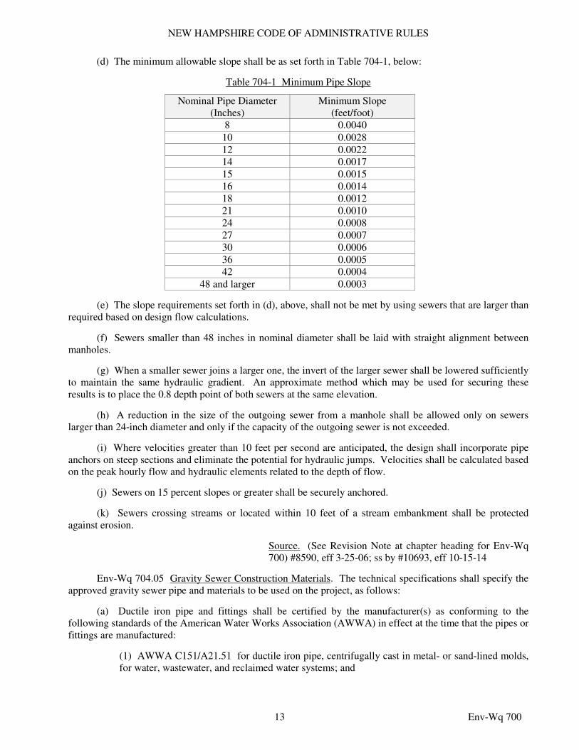
(d) The minimum allowable slope shall be as set forth in Table 704-1, below:
Table 704-1 Minimum Pipe Slope
Nominal Pipe Diameter
(Inches) Minimum Slope
(feet/foot) 8 0.0040
10 0.0028 12 0.0022 14 0.0017 15 0.0015 16 0.0014 18 0.0012 21 0.0010 24 0.0008 27 0.0007 30 0.0006 36 0.0005 42 0.0004
48 and larger 0.0003
(e) The slope requirements set forth in (d), above, shall not be met by using sewers that are larger than required based on design flow calculations.
(f) Sewers smaller than 48 inches in nominal diameter shall be laid with straight alignment between manholes.
(g) When a smaller sewer joins a larger one, the invert of the larger sewer shall be lowered sufficiently to maintain the same hydraulic gradient. An approximate method which may be used for securing these results is to place the 0.8 depth point of both sewers at the same elevation.
(h) A reduction in the size of the outgoing sewer from a manhole shall be allowed only on sewers larger than 24-inch diameter and only if the capacity of the outgoing sewer is not exceeded.
(i) Where velocities greater than 10 feet per second are anticipated, the design shall incorporate pipe anchors on steep sections and eliminate the potential for hydraulic jumps. Velocities shall be calculated based on the peak hourly flow and hydraulic elements related to the depth of flow.
(j) Sewers on 15 percent slopes or greater shall be securely anchored.
(k) Sewers crossing streams or located within 10 feet of a stream embankment shall be protected against erosion.
Source. (See Revision Note at chapter heading for Env-Wq 700) #8590, eff 3-25-06; ss by #10693, eff 10-15-14
Env-Wq 704.05 Gravity Sewer Construction Materials. The technical specifications shall specify the approved gravity sewer pipe and materials to be used on the project, as follows:
(a) Ductile iron pipe and fittings shall be certified by the manufacturer(s) as conforming to the following standards of the American Water Works Association (AWWA) in effect at the time that the pipes or fittings are manufactured:
(1) AWWA C151/A21.51 for ductile iron pipe, centrifugally cast in metal- or sand-lined molds, for water, wastewater, and reclaimed water systems; and
NEW HAMPSHIRE CODE OF ADMINISTRATIVE RULES
14 Env-Wq 700
(2) AWWA C150/A21.50 for thickness design of ductile iron pipe and with ASTM A536 for ductile iron castings;
(b) Joints shall be mechanical type, push-on type, or ball-and-socket type as appropriate for the specific application;
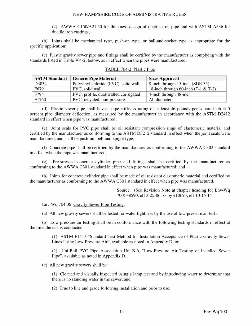
(c) Plastic gravity sewer pipe and fittings shall be certified by the manufacturer as complying with the standards listed in Table 704-2, below, as in effect when the pipes were manufactured:
TABLE 704-2 Plastic Pipe
ASTM Standard Generic Pipe Material Sizes Approved
D3034 Polyvinyl chloride (PVC), solid wall 8-inch through 15-inch (SDR 35) F679 PVC, solid wall 18-inch through 60-inch (T-1 & T-2) F794 PVC, profile, dual-walled corrugated 4-inch through 48-inch F1760 PVC, recycled, non-pressure All diameters
(d) Plastic sewer pipe shall have a pipe stiffness rating of at least 46 pounds per square inch at 5 percent pipe diameter deflection, as measured by the manufacturer in accordance with the ASTM D2412 standard in effect when pipe was manufactured;
(e) Joint seals for PVC pipe shall be oil resistant compression rings of elastomeric material and certified by the manufacturer as conforming to the ASTM D3212 standard in effect when the joint seals were manufactured, and shall be push-on, bell-and-spigot type;
(f) Concrete pipe shall be certified by the manufacturer as conforming to the AWWA C302 standard in effect when the pipe was manufactured;
(g) Pre-stressed concrete cylinder pipe and fittings shall be certified by the manufacturer as conforming to the AWWA C301 standard in effect when pipe was manufactured; and
(h) Joints for concrete cylinder pipe shall be made of oil resistant elastomeric material and certified by the manufacturer as conforming to the AWWA C301 standard in effect when pipe was manufactured.
Source. (See Revision Note at chapter heading for Env-Wq 700) #8590, eff 3-25-06; ss by #10693, eff 10-15-14
Env-Wq 704.06 Gravity Sewer Pipe Testing.
(a) All new gravity sewers shall be tested for water tightness by the use of low-pressure air tests.
(b) Low-pressure air testing shall be in conformance with the following testing standards in effect at the time the test is conducted:
(1) ASTM F1417 “Standard Test Method for Installation Acceptance of Plastic Gravity Sewer Lines Using Low-Pressure Air”, available as noted in Appendix D; or
(2) Uni-Bell PVC Pipe Association Uni-B-6, “Low-Pressure Air Testing of Installed Sewer Pipe”, available as noted in Appendix D.
(c) All new gravity sewers shall be:
(1) Cleaned and visually inspected using a lamp test and by introducing water to determine that there is no standing water in the sewer; and
(2) True to line and grade following installation and prior to use.
NEW HAMPSHIRE CODE OF ADMINISTRATIVE RULES
15 Env-Wq 700
(d) All plastic sewer pipe shall be visually inspected and deflection tested not less than 30 days nor more than 90 days following installation.
(e) The maximum allowable deflection of flexible sewer pipe shall be 5% percent of average inside diameter. A rigid ball or mandrel with a diameter of at least 95% of the average inside pipe diameter shall be used for testing pipe deflection. The deflection test shall be conducted without mechanical pulling devices.
Source. (See Revision Note at chapter heading for Env-Wq 700) #8590, eff 3-25-06; ss by #10693, eff 10-15-14
Env-Wq 704.07 Details of Design and Construction of Force Mains and Pressure Sewers.
(a) Force mains for constant speed pumps shall be sized to yield a cleansing velocity of 3 feet per second or greater at design pump capacity.
(b) Force mains for variable speed pumps shall be sized to yield a velocity of 2 feet per second or greater at average daily design flow.
(c) Force mains shall be 4 inches or larger in nominal diameter.
(d) Pressure sewers shall be 1.5 inches or larger in nominal diameter.
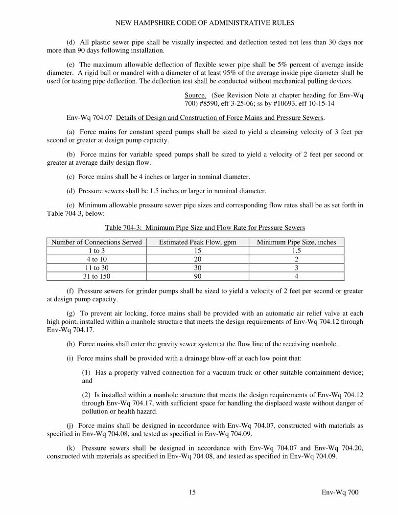
(e) Minimum allowable pressure sewer pipe sizes and corresponding flow rates shall be as set forth in Table 704-3, below:
Table 704-3: Minimum Pipe Size and Flow Rate for Pressure Sewers
Number of Connections Served Estimated Peak Flow, gpm Minimum Pipe Size, inches
1 to 3 15 1.5
4 to 10 20 2
11 to 30 30 3
31 to 150 90 4
(f) Pressure sewers for grinder pumps shall be sized to yield a velocity of 2 feet per second or greater at design pump capacity.
(g) To prevent air locking, force mains shall be provided with an automatic air relief valve at each high point, installed within a manhole structure that meets the design requirements of Env-Wq 704.12 through Env-Wq 704.17.
(h) Force mains shall enter the gravity sewer system at the flow line of the receiving manhole.
(i) Force mains shall be provided with a drainage blow-off at each low point that:
(1) Has a properly valved connection for a vacuum truck or other suitable containment device; and
(2) Is installed within a manhole structure that meets the design requirements of Env-Wq 704.12 through Env-Wq 704.17, with sufficient space for handling the displaced waste without danger of pollution or health hazard.
(j) Force mains shall be designed in accordance with Env-Wq 704.07, constructed with materials as specified in Env-Wq 704.08, and tested as specified in Env-Wq 704.09.
(k) Pressure sewers shall be designed in accordance with Env-Wq 704.07 and Env-Wq 704.20, constructed with materials as specified in Env-Wq 704.08, and tested as specified in Env-Wq 704.09.
NEW HAMPSHIRE CODE OF ADMINISTRATIVE RULES
16 Env-Wq 700
(l) Thrust blocks made from inorganic, corrosion-resistant material shall be placed at all bends, elbows, tees, and junctions.
(m) Force mains shall be designed to withstand instantaneous hydrostatic pressures of at least 2.5 times the design total dynamic head or at least 100 psi, whichever is greater.
Source. (See Revision Note at chapter heading for Env-Wq 700) #8590, eff 3-25-06; ss by #10693, eff 10-15-14
Env-Wq 704.08 Force Main and Pressure Sewer Construction Materials.
(a) Force mains and pressure sewers shall be constructed of ductile iron (DI), high density polyethylene (HDPE), or PVC material.
(b) Force mains and pressure sewers shall be treated as gravity sewers for purposes of foundation bedding and backfill requirements.
(c) PVC pipe used for force mains and pressure sewers shall be certified by its manufacturer as conforming to the ASTM D2241 or ASTM D1785 standards in effect when the pipe is manufactured.
(d) HDPE pipe used for force mains and pressure sewers shall be certified by its manufacturer as conforming to the ASTM D3035 standard in effect when the pipe is manufactured.
(e) If DI pipe is used in an environment that could cause corrosion or other deterioration of or damage to an iron pipe, or otherwise reduce the typical life expectancy of the pipe, such as may occur with certain soil types, low pH levels, or water conditions, the pipe shall be protected against corrosion, such as with cathodic protection.
Source. (See Revision Note at chapter heading for Env-Wq 700) #8590, eff 3-25-06; ss by #10693, eff 10-15-14
Env-Wq 704.09 Force Main and Pressure Sewer Testing. Force mains and pressure sewers shall be tested in accordance with section 5 of the AWWA C600, “Installation of Cast Iron Water Mains and Their Appurtenances” standard in effect when the test is conducted, available as noted in Appendix D, at a pressure equal to the greater of 150 percent of the design operating total dynamic head or at least 100 psi.
Source. (See Revision Note at chapter heading for Env-Wq 700) #8590, eff 3-25-06; ss by #10693, eff 10-15-14
Env-Wq 704.10 Grinder Pumps for Pressure Sewers.
(a) A pressure sewer system shall have at least one grinder pump at each building or residence that is connected to the system.
(b) The minimum capacity requirements for each grinder pump connected to a pressure sewer system shall be determined based on hydraulic modeling of the entire pressure sewer system and the main sewer to which the pressure sewer is proposed to be connected.
(c) Grinder pumps for pressure sewer systems shall be:
(1) Wet well type;
(2) Readily removable without manual disconnection of piping;
(3) Rotating type with a stationary hardened and ground stainless steel shredding ring with stainless steel cutters;
NEW HAMPSHIRE CODE OF ADMINISTRATIVE RULES
17 Env-Wq 700
(4) Capable of reducing all components in typical domestic sewage, including a reasonable number of foreign objects, including but not limited to wood, paper, plastic, glass, and rubber, to a size that will pass through pump passages and a 1.25-inch nominal diameter pipe;
(5) Positioned so solids are fed into pump from the bottom in an upward flow;
(6) Capable of processing foreign objects without jamming, stalling, or overloading;
(7) Accessible for maintenance and replacement;
(8) Installed within a manhole meeting the requirements of Env-Wq 704.12 through Env-Wq 704.17 or in a tank meeting the requirements of Env-Wq 704.10(d); and
(9) Equipped with:
a. Non-fouling sensing devices for high level alarms;
b. A visible alarm light; and
c. An audible alarm.
(d) A grinder pump tank shall consist of:
(1) A manhole meeting the requirements of Env-Wq 704.12 through Env-Wq 704.17;
(2) A reinforced concrete tank meeting HS-20 requirements;
(3) A high density polyethylene tank; or
(4) A fiberglass-reinforced polyester resin using a filament wound process, layup and spray technique.
Source. (See Revision Note at chapter heading for Env-Wq 700) #8590, eff 3-25-06; ss by #10693, eff 10-15-14
Env-Wq 704.11 Trench Construction.
(a) Pipe trench bedding material for excavation below grade shall be screened gravel or crushed stone meeting the ASTM C33/C33M stone size No. 67 standard in effect when the stone is used, available as noted in Appendix D.
(b) Subject to (c), below, the pipe sand blanket material shall be graded sand free from organic materials, graded such that 100 percent passes a ½-inch sieve and a maximum of 15 percent passes a #200 sieve.
(c) In lieu of the sand blanket specified in (b), above, a stone envelope 6 inches thick completely around the pipe using ¾-inch stone may be used.
(d) Pipe bedding material shall extend from a horizontal plane through the pipe axis to 6 inches below the bottom of the outside surface of the pipe.
(e) Pipe sand blanket material shall cover the pipe a minimum of 12 inches above the crown of the outside surface.
(f) Compaction shall be in 12-inch layers for bedding and blanket materials.
(g) Backfill material shall be compacted in no more than 3-foot thick layers to the ground surface except for road construction where the final 3 feet shall be compacted in no more than 12-inch thick layers to the road base surface.
NEW HAMPSHIRE CODE OF ADMINISTRATIVE RULES
18 Env-Wq 700
(h) Trench backfill material in roadway locations shall be natural materials excavated from the trench during construction, excluding:
(1) Debris;
(2) Pieces of pavement;
(3) Organic matter;
(4) Top soil;
(5) Wet or soft muck;
(6) Peat or clay;
(7) Excavated ledge material;
(8) Rocks over 6 inches in the largest dimension; and
(9) Any material not approved by the engineer.
(i) Trench backfill at cross-country locations shall be as described in (h), above, except that top soil, loam, muck or peat may be used provided the completed construction will be stable, and provided that access to the sewer for maintenance and reconstruction is preserved.
(j) Backfill shall be mounded 6 inches above original ground at cross country locations.
(k) Base course for trench repair shall meet the requirements of Division 300 of the “Standard Specifications for Road and Bridge Construction” of the New Hampshire department of transportation as available at http://www.nh.gov/dot/org/projectdevelopment/highwaydesign/specifications/index.htm
(l) Where sheeting is placed alongside the pipe and extends below mid-diameter, the sheeting shall be cut off and left in place to an elevation not less than one foot above the top of the pipe and at least 3 feet below finished grade.
(m) Trenches for sewer pipes with slopes over 0.08 feet per foot, trenches for sewer pipes below seasonal high ground water level, and trenches for sewer pipes downstream of and within the hydraulic influence of waterways or wetlands shall have impervious trench dams constructed every 300 feet to prevent potential disturbance to pipe bedding and blanket materials.
(n) Precautions shall be taken to avoid groundwater pooling at the surface by providing drainage to a suitable outlet at catch basins or run-off swales.
(o) For trenches for sewer pipes in ledge, excavation shall extend to at least 12 inches below the bottom of the sewer pipe.
(p) All sewers shall be marked using metal-impregnated marking tape or tracer wire that can be located using metal detection equipment.
Source. (See Revision Note at chapter heading for Env-Wq 700) #8590, eff 3-25-06; ss by #10693, eff 10-15-14
Env-Wq 704.12 Manholes: General Construction Requirements.
(a) All component parts of manhole structures shall have the strength, leak resistance, and space necessary for the intended service.
(b) Manhole structures shall have a life expectancy of at least 25 years.
NEW HAMPSHIRE CODE OF ADMINISTRATIVE RULES
19 Env-Wq 700
(c) Manhole structures shall be designed to withstand HS-20 loading and shall not leak in excess of one gpd per vertical foot of manhole for the life of the structure.
(d) Barrels, cone sections, and concrete grade rings shall be constructed of precast reinforced concrete.
(e) Base sections shall be of monolithic construction to a point at least 6 inches above the crown of the incoming pipe.
(f) Horizontal joints between sections of precast concrete barrels shall be of an overlapping type, sealed for water-tightness using a double row of an elastomeric or mastic-like sealant.
(g) Pipe to manhole joints shall be as follows:
(1) Elastomeric, rubber sleeve with watertight joints at the manhole opening and pipe surfaces;
(2) Cast into the wall or secured with stainless steel clamps;
(3) Elastomeric sealing ring cast in the manhole opening with seal formed on the surface of the pipe by compression of the ring; and
(4) Non-shrink grouted joints where watertight bonding to the manhole and pipe can be obtained.
(h) Manhole cone sections shall be eccentric in shape.
(i) All precast sections and bases shall have the date of manufacture and the name or trademark of the manufacturer impressed or indelibly marked on the inside wall.
(j) All precast sections and bases shall be coated on the exterior with a bituminous damp-proofing coating.
(k) Manholes that are not replacing existing manholes shall have a brick paved shelf and invert constructed to conform to the size of pipe and flow. At changes in direction, the inverts shall be laid out in curves of the longest radius possible tangent to the center line of the sewer pipes. Shelves shall be constructed to the elevation of the highest pipe crown and sloped to drain toward the flowing through channel. Underlayment of invert and shelf shall consist of brick masonry. Inverts and shelves shall be placed after testing of the manhole.
(l) Replacement manholes where there is an established line and grade through which the sewer enters and exits the manhole shall have:
(1) A brick paved shelf and invert constructed to conform to the size of pipe and flow as required in (k) above;
(2) A precast concrete shelf and invert with the shelf constructed to the elevation of the highest pipe crown and sloped to drain toward the flowing through channel; or
(3) A fiberglass insert with the shelf constructed to the elevation of the highest pipe crown and sloped to drain toward the flowing through channel.
(m) When manhole depth is less than 6 feet, a reinforced concrete slab cover may be used in lieu of a cone section, provided the slab has an eccentric entrance opening and be capable of supporting HS-20 loads.
(n) The minimum internal diameter of manholes shall be 48 inches. For sewers larger than 24-inch diameter, manhole diameters shall be increased so as to provide at least 12 inches of shelf on each side of the sewer.
(o) In the flow channel, a drop of at least 0.1 feet shall be provided between incoming and outgoing sewers on all manholes.
NEW HAMPSHIRE CODE OF ADMINISTRATIVE RULES
20 Env-Wq 700
(p) Slope across manholes shall be the average slope of the incoming and outgoing sewers. Design shall include measures to prevent hydraulic jumps across the manholes.
(q) Watertight manhole covers shall be used for all manholes located in flood-prone areas as determined by the municipality.
(r) Electrical equipment installed or used in manholes shall conform to the National Electric Code (NEC) adopted by reference in the state building code pursuant to RSA 155-A:1, IV, for installation in areas classified by the NEC as Class 1, Division 1.
(s) Precast bases shall be placed on a 6-inch layer of compacted bedding material that conforms to the ASTM C33/C33M No. 67 stone standard in effect when the stone is processed by the manufacturer, available as noted in Appendix D. The excavation shall be dewatered while placing bedding material and setting the base or pouring concrete.
Source. (See Revision Note at chapter heading for Env-Wq 700) #8590, eff 3-25-06; ss by #10693, eff 10-15-14
Env-Wq 704.13 Manholes: Materials of Construction.
(a) Materials of construction for manholes shall be as follows: (1) Concrete for manholes and concrete grade rings shall conform to the requirements for class AA concrete in the New Hampshire department of transportation’s “Standard Specifications for Road and Bridge Construction” as available at http://www.nh.gov/dot/org/projectdevelopment/highwaydesign/specifications/index.htm
(2) Reinforcing for concrete manholes and concrete grade rings shall be steel or structural fibers that conform to the New Hampshire department of transportation’s “Standard Specifications for Road and Bridge Construction” as available at http://www.nh.gov/dot/org/projectdevelopment/highwaydesign/specifications/index.htm
(3) Precast concrete barrel sections, cones, and bases shall be certified by their manufacturer(s) as conforming to the ASTM C478 standard in effect at the time the barrel sections, cones, and bases are manufactured;
(4) The manhole frame and cover shall provide a 30-inch diameter clear opening;
(5) The manhole cover shall have the word “SEWER” in 3-inch letters cast into the top surface;
(6) The castings shall be of even-grained cast iron, smooth, and free from scale, lumps, blisters, sand holes, and defects;
(7) Contact surfaces of covers and frames shall be machined at the foundry to prevent rocking of covers in any orientation;
(8) Castings shall be equal to class 30 and certified by their manufacturer as conforming to the ASTM A48/48M standard in effect at the time the castings were manufactured;
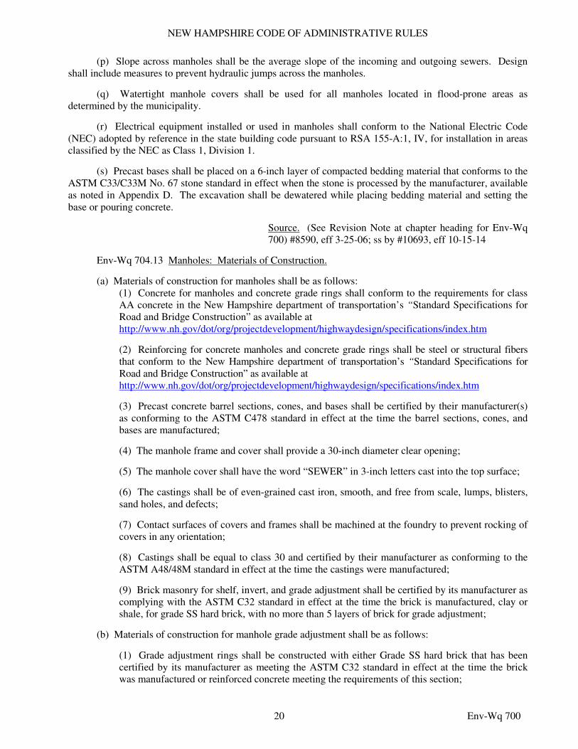
(9) Brick masonry for shelf, invert, and grade adjustment shall be certified by its manufacturer as complying with the ASTM C32 standard in effect at the time the brick is manufactured, clay or shale, for grade SS hard brick, with no more than 5 layers of brick for grade adjustment;
(b) Materials of construction for manhole grade adjustment shall be as follows:
(1) Grade adjustment rings shall be constructed with either Grade SS hard brick that has been certified by its manufacturer as meeting the ASTM C32 standard in effect at the time the brick was manufactured or reinforced concrete meeting the requirements of this section;
NEW HAMPSHIRE CODE OF ADMINISTRATIVE RULES
21 Env-Wq 700
(2) Grade adjustment rings shall:
a. Be sized to the opening of the manhole; and
b. Not obstruct the access to the manhole.
(c) Mortar used in manhole construction shall comply with the following:
(1) Mortar shall be composed of Type II Portland cement and sand with or without hydrated lime addition;
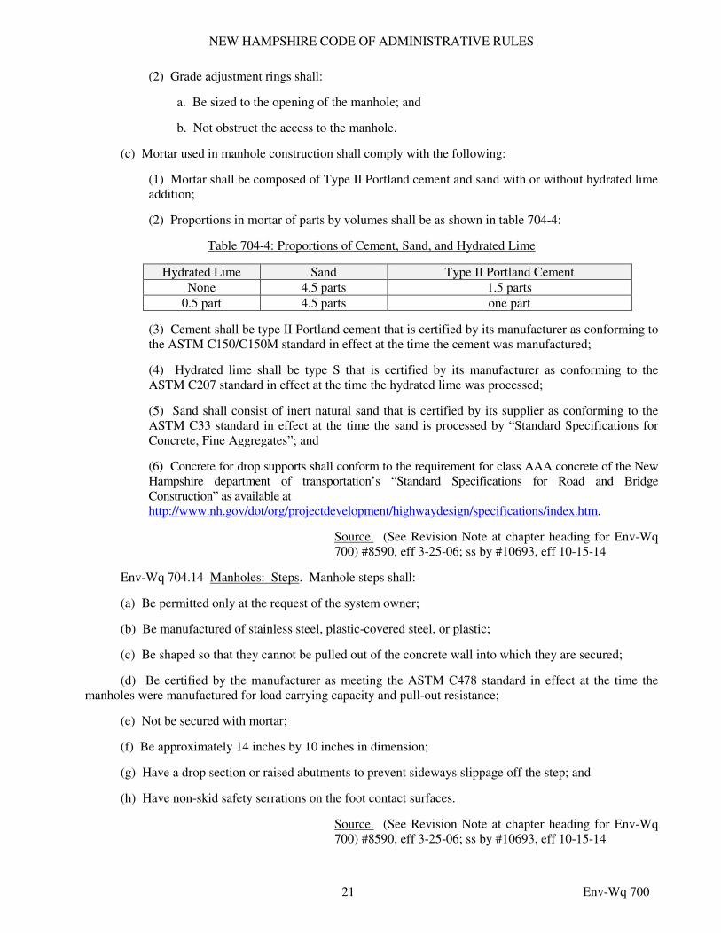
(2) Proportions in mortar of parts by volumes shall be as shown in table 704-4:
Table 704-4: Proportions of Cement, Sand, and Hydrated Lime
Hydrated Lime Sand Type II Portland Cement
None 4.5 parts 1.5 parts
0.5 part 4.5 parts one part
(3) Cement shall be type II Portland cement that is certified by its manufacturer as conforming to the ASTM C150/C150M standard in effect at the time the cement was manufactured;
(4) Hydrated lime shall be type S that is certified by its manufacturer as conforming to the ASTM C207 standard in effect at the time the hydrated lime was processed;
(5) Sand shall consist of inert natural sand that is certified by its supplier as conforming to the ASTM C33 standard in effect at the time the sand is processed by “Standard Specifications for Concrete, Fine Aggregates”; and
(6) Concrete for drop supports shall conform to the requirement for class AAA concrete of the New Hampshire department of transportation’s “Standard Specifications for Road and Bridge Construction” as available at http://www.nh.gov/dot/org/projectdevelopment/highwaydesign/specifications/index.htm.
Source. (See Revision Note at chapter heading for Env-Wq 700) #8590, eff 3-25-06; ss by #10693, eff 10-15-14
Env-Wq 704.14 Manholes: Steps. Manhole steps shall:
(a) Be permitted only at the request of the system owner;
(b) Be manufactured of stainless steel, plastic-covered steel, or plastic;
(c) Be shaped so that they cannot be pulled out of the concrete wall into which they are secured;
(d) Be certified by the manufacturer as meeting the ASTM C478 standard in effect at the time the manholes were manufactured for load carrying capacity and pull-out resistance;
(e) Not be secured with mortar;
(f) Be approximately 14 inches by 10 inches in dimension;
(g) Have a drop section or raised abutments to prevent sideways slippage off the step; and
(h) Have non-skid safety serrations on the foot contact surfaces.
Source. (See Revision Note at chapter heading for Env-Wq 700) #8590, eff 3-25-06; ss by #10693, eff 10-15-14
NEW HAMPSHIRE CODE OF ADMINISTRATIVE RULES
22 Env-Wq 700
Env-Wq 704.15 Manholes: Placement. Manholes shall be located as follows:
(a) Manholes shall be installed at the end of each gravity sewer, force main, and pressure sewer, at all intersections, and at all changes in grade, size, or alignment.
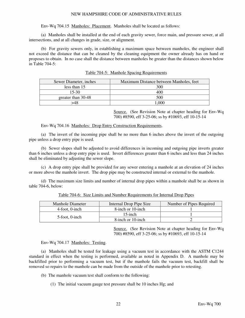
(b) For gravity sewers only, in establishing a maximum space between manholes, the engineer shall not exceed the distance that can be cleaned by the cleaning equipment the owner already has on hand or proposes to obtain. In no case shall the distance between manholes be greater than the distances shown below in Table 704-5:
Table 704-5: Manhole Spacing Requirements
Sewer Diameter, inches Maximum Distance between Manholes, feet
less than 15 300
15-30 400
greater than 30-48 500
>48 1,000
Source. (See Revision Note at chapter heading for Env-Wq 700) #8590, eff 3-25-06; ss by #10693, eff 10-15-14
Env-Wq 704.16 Manholes: Drop Entry Construction Requirements.
(a) The invert of the incoming pipe shall be no more than 6 inches above the invert of the outgoing pipe unless a drop entry pipe is used.
(b) Sewer slopes shall be adjusted to avoid differences in incoming and outgoing pipe inverts greater than 6 inches unless a drop entry pipe is used. Invert differences greater than 6 inches and less than 24 inches shall be eliminated by adjusting the sewer slope.
(c) A drop entry pipe shall be provided for any sewer entering a manhole at an elevation of 24 inches or more above the manhole invert. The drop pipe may be constructed internal or external to the manhole.
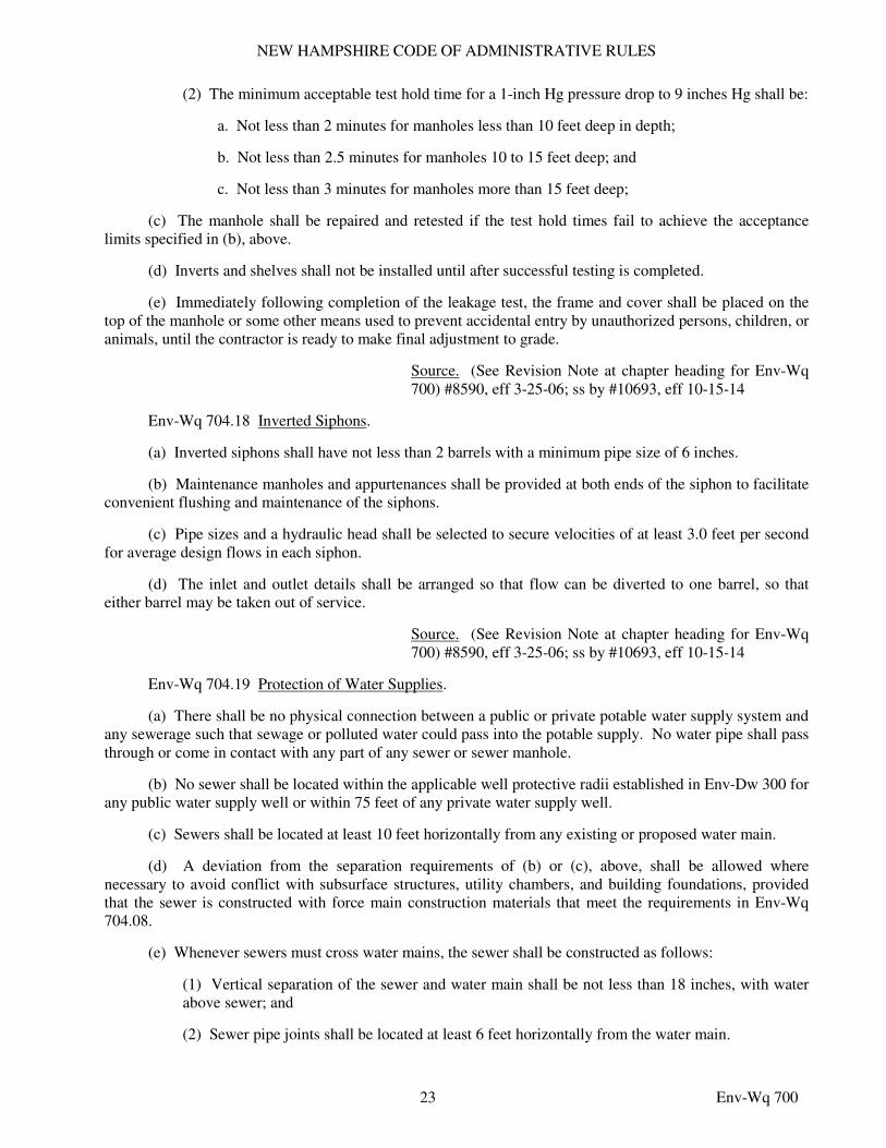
(d) The maximum size limits and number of internal drop pipes within a manhole shall be as shown in table 704-6, below:
Table 704-6: Size Limits and Number Requirements for Internal Drop Pipes
Manhole Diameter Internal Drop Pipe Size Number of Pipes Required
4-foot, 0-inch 8-inch or 10-inch 1
5-foot, 0-inch 15-inch 1
8-inch or 10-inch 2
Source. (See Revision Note at chapter heading for Env-Wq 700) #8590, eff 3-25-06; ss by #10693, eff 10-15-14
Env-Wq 704.17 Manholes: Testing.
(a) Manholes shall be tested for leakage using a vacuum test in accordance with the ASTM C1244 standard in effect when the testing is performed, available as noted in Appendix D. A manhole may be backfilled prior to performing a vacuum test, but if the manhole fails the vacuum test, backfill shall be removed so repairs to the manhole can be made from the outside of the manhole prior to retesting.
(b) The manhole vacuum test shall conform to the following:
(1) The initial vacuum gauge test pressure shall be 10 inches Hg; and
NEW HAMPSHIRE CODE OF ADMINISTRATIVE RULES
23 Env-Wq 700
(2) The minimum acceptable test hold time for a 1-inch Hg pressure drop to 9 inches Hg shall be:
a. Not less than 2 minutes for manholes less than 10 feet deep in depth;
b. Not less than 2.5 minutes for manholes 10 to 15 feet deep; and
c. Not less than 3 minutes for manholes more than 15 feet deep;
(c) The manhole shall be repaired and retested if the test hold times fail to achieve the acceptance limits specified in (b), above.
(d) Inverts and shelves shall not be installed until after successful testing is completed.
(e) Immediately following completion of the leakage test, the frame and cover shall be placed on the top of the manhole or some other means used to prevent accidental entry by unauthorized persons, children, or animals, until the contractor is ready to make final adjustment to grade.
Source. (See Revision Note at chapter heading for Env-Wq 700) #8590, eff 3-25-06; ss by #10693, eff 10-15-14
Env-Wq 704.18 Inverted Siphons.
(a) Inverted siphons shall have not less than 2 barrels with a minimum pipe size of 6 inches.
(b) Maintenance manholes and appurtenances shall be provided at both ends of the siphon to facilitate convenient flushing and maintenance of the siphons.
(c) Pipe sizes and a hydraulic head shall be selected to secure velocities of at least 3.0 feet per second for average design flows in each siphon.
(d) The inlet and outlet details shall be arranged so that flow can be diverted to one barrel, so that either barrel may be taken out of service.
Source. (See Revision Note at chapter heading for Env-Wq 700) #8590, eff 3-25-06; ss by #10693, eff 10-15-14
Env-Wq 704.19 Protection of Water Supplies.
(a) There shall be no physical connection between a public or private potable water supply system and any sewerage such that sewage or polluted water could pass into the potable supply. No water pipe shall pass through or come in contact with any part of any sewer or sewer manhole.
(b) No sewer shall be located within the applicable well protective radii established in Env-Dw 300 for any public water supply well or within 75 feet of any private water supply well.
(c) Sewers shall be located at least 10 feet horizontally from any existing or proposed water main.
(d) A deviation from the separation requirements of (b) or (c), above, shall be allowed where necessary to avoid conflict with subsurface structures, utility chambers, and building foundations, provided that the sewer is constructed with force main construction materials that meet the requirements in Env-Wq 704.08.
(e) Whenever sewers must cross water mains, the sewer shall be constructed as follows:
(1) Vertical separation of the sewer and water main shall be not less than 18 inches, with water above sewer; and
(2) Sewer pipe joints shall be located at least 6 feet horizontally from the water main.
NEW HAMPSHIRE CODE OF ADMINISTRATIVE RULES
24 Env-Wq 700
Source. (See Revision Note at chapter heading for Env-Wq 700) #8590, eff 3-25-06; ss by #10693, eff 10-15-14
Env-Wq 704.20 Service Connections.
(a) Service connections shall use sanitary tee or wye fittings for all new sewer construction.
(b) The centerline of all building connections shall enter the top half of the sewer.
(c) Any service connection with a vertical rise up to 4 feet may have the sewer fitting set vertically.
(d) Any service connection with a vertical rise up to 12 feet shall employ non-encased risers that protect against pipe penetration or failure at the fitting by the use of bell-on-bell connections.
(e) For existing sewers where fittings cannot be installed, saddle connections shall be used.
(f) Pressure sewerage shall have an isolation valve or curb stop valve installed at the property line. If a check valve is used at the property line, the valve shall be installed within a vault to facilitate maintenance.
(g) Roof downspouts, exterior or interior foundation drains, sump pumps, or other sources of surface water run-off or groundwater shall not be directly or indirectly connected to a public sewer.
Source. (See Revision Note at chapter heading for Env-Wq 700) #8590, eff 3-25-06; ss by #10693, eff 10-15-14
PART Env-Wq 705 SEWAGE PUMPING STATIONS
Env-Wq 705.01 Sewage Pumping Station Design Requirements: Flooding and Weather Protection.
(a) Sewage pumping stations shall be designed for uninterrupted operation during a 25-year flood, and shall be protected against damage from a 100-year flood. The sewage pumping station shall be readily accessible.
(b) Flood elevations shall be determined using flood maps or in accordance with Env-Wq 1503.09 (f)(1) and (f)(2).
(c) Each sewage pumping station shall be protected against extreme weather conditions, such as excessive heat or humidity or excessively cold temperatures, that could cause the pump station components to stop functioning.
Source. (See Revision Note at chapter heading for Env-Wq 700) #8590, eff 3-25-06; ss by #10693, eff 10-15-14
Env-Wq 705.02 Sewage Pumping Station Design Requirements: Wet Well and Dry Well Construction.
(a) The wet well and the discharge manifold shall be configured to prevent grit from settling back into pump discharge lines of pumps that are not operating.
(b) Wet and dry wells including their superstructure shall be completely separated and sealed.
(c) Wet well design shall avoid vortexing and air entrainment near the pump suction intakes.
(d) A separate sump pump shall be provided in the dry well to remove leakage or drainage, with the discharge above the alarm level of the wet well.
(e) Wet wells for sewage pumping stations of greater than 200 gpm capacity shall have either:
(1) Division walls so that the station can be kept in operation when work is required in the wet well; or
NEW HAMPSHIRE CODE OF ADMINISTRATIVE RULES
25 Env-Wq 700
(2) A bypass connection to allow for connection of a pump around the wet well for maintenance, repairs and construction.
(f) The effective capacity of the wet well shall be based on the cycle time of the pumps for constant speed operation so as to prevent short cycling of the pumps.
(g) The wet well floor shall have a minimum slope of 1 to 1 to the hopper bottom.
(h) The horizontal area of the hopper bottom shall be limited to that area required for proper installation and function of the inlet.
(i) Wet wells shall be tested prior to operation using exfiltration testing method ACI 350.1 Method HST-NML in effect at the time the wet well is installed, available as noted in Appendix D. Any visible signs of leakage shall be repaired and retested prior to placing the wet well in service.
Source. (See Revision Note at chapter heading for Env-Wq 700) #8590, eff 3-25-06; ss by #10693, eff 10-15-14
Env-Wq 705.03 Sewage Pumping Station Design Requirements: Allowable Pump Types, Pump Controls and Pump Size.
(a) The following types of sewage pumping stations shall be allowed:
(1) Dry well/wet well type design with pumps and drives located in a separate dry chamber with flooded suctions;
(2) Suction lift type with pumps and drives in a separate dry chamber; and
(3) Submersible type with pumps submerged.
(b) A minimum of 2 pumps, each designed to handle peak hourly flows, shall be provided.
(c) Where 3 or more pumps are provided, they shall be designed such that, with any one unit out of service, the remaining units shall have the capacity to handle peak hourly sewage flows.
(d) The use of jockey pumps shall be evaluated to optimize the efficiency of the pumping station operation.
(e) All pumps shall be protected from damage due to large solid objects.
(f) Pumps shall be capable of passing 3-inch solids, or 2.5-inch solids if preceded by a grinder unit.
(g) Submersible pumps shall be capable of removal without disconnecting pipes or dewatering and reseating using non-corroding guide rails or cables.
(h) Self-priming suction lift pump systems shall be designed such that:
(1) The system’s reprime capacity is greater than the static suction head; and
(2) The system’s available net positive suction head is at least 6 feet greater than the required net positive suction head.
(i) Pumps shall be protected by check valves from being driven in the reverse direction.
(j) Pump controls shall provide autostart of lag pump should lead pump fail to start.
(k) Flooded suction pumping systems shall be designed such that:
(1) Shut-off valves are provided in the suction piping;
NEW HAMPSHIRE CODE OF ADMINISTRATIVE RULES
26 Env-Wq 700
(2) Shut-off valves and check valves are provided in the discharge piping; and
(3) Discharge shut-off valves are located downstream of the check valve.
(l) Shut-off and check valves for submersible pumps shall be placed in a separate chamber for ease of maintenance.
Source. (See Revision Note at chapter heading for Env-Wq 700) #8590, eff 3-25-06; ss by #10693, eff 10-15-14
Env-Wq 705.04 Sewage Pumping Station Design Requirements: Pump Station Access. Sewage pumping stations shall meet the following requirements:
(a) Dry wells shall provide accessibility for the repair and removal of pumps, motors, and other items of equipment that are essential to the sewage pumping process;
(b) Separate exterior entrances shall be provided to both wet wells and dry wells of sewage pumping stations;
(c) For built-in-place sewage pumping stations, access to lower levels shall be by stairways with handrails;
(d) Prefabricated stations may have ladders with less than or equal to a 75 degree slope or spiral stairs;
(e) Vertical distances between floors or rest landings shall not exceed 12 feet;
(f) Safety barriers to prevent falling shall be provided at landings;
(g) Power elevators proposed for all deep stations shall have a capacity limit of not less than 600 pounds;
(h) Lifting equipment shall be provided for submersible pump removal; and
(i) Lifting chains shall be stainless steel or other corrosion resistant material.
Source. (See Revision Note at chapter heading for Env-Wq 700) #8590, eff 3-25-06; ss by #10693, eff 10-15-14
Env-Wq 705.05 Sewage Pumping Station Design Requirements: Flow and Pump Usage Measurement.
(a) Sewage pumping stations with capacities of more than 250 gpm or equipped with variable speed pumps shall have continuous flow recording and totalizer capability.
(b) Sewage pumping stations equipped with constant speed pumps with capacities of 250 gpm or less shall have:
(1) A running meter that indicates the cumulative running time of each pump; or
(2) The continuous flow recording and totalizer capability as per (a), above.
Source. (See Revision Note at chapter heading for Env-Wq 700) #8590, eff 3-25-06; ss by #10693, eff 10-15-14
Env-Wq 705.06 Sewage Pumping Station Design Requirements: Potable Water Restrictions and Protection.
(a) Where potable water is used for pump sealing purposes, the potable water supply shall be protected by a break tank or reduced pressure zone back flow preventer.
NEW HAMPSHIRE CODE OF ADMINISTRATIVE RULES
27 Env-Wq 700
(b) Water ejectors connected to a potable water supply shall be prohibited.
(c) All floor and walkway surfaces shall slope to a point of discharge.
(d) Connections between raw, partially treated, or fully treated sewage and potable water shall be prohibited unless adequate backflow prevention equipment is installed.
Source. (See Revision Note at chapter heading for Env-Wq 700) #8590, eff 3-25-06; ss by #10693, eff 10-15-14
Env-Wq 705.07 Sewage Pumping Station Electrical Requirements.
(a) Submersible pumps for sewage pumping stations shall conform to the NEC requirements adopted by reference in the state building code pursuant to RSA 155-A:1, IV, for installation in areas classified by the NEC as class I, division 1.
(b) Electrical systems and components, including motors, lights, cable, conduits, switch boxes, and control circuits shall be protected from flooding in accordance with Env-Wq 705.01.
(c) Electrical systems and components including motors, lights, cable, conduits, switch boxes and control circuits in enclosed or partially enclosed spaces where flammable mixtures occasionally may be present, including raw sewage wet wells, shall be certified by their manufacturer as:
(1) Complying with the NEC requirements adopted by reference in the state building code pursuant to RSA 155-A:1, IV, for class I, division 1 locations; or
(2) Being rated for class I division 2 requirements where mechanical ventilation is provided in accordance with the NFPA as adopted by reference in the state fire code in Saf-C 6000.
(d) All electrical equipment and work shall comply with the requirements of NEC as adopted by reference in the state building code pursuant to RSA 155-A:1, IV, and NFPA as adopted by reference in the state fire code in Saf-C 6000 in effect at the time of installation.
Source. (See Revision Note at chapter heading for Env-Wq 700) #8590, eff 3-25-06; ss by #10693, eff 10-15-14
Env-Wq 705.08 Sewage Pumping Station Ventilation Requirements.
(a) Mechanical ventilation for personnel and equipment shall be provided for all occupied spaces within sewage pumping stations in accordance with the NFPA as incorporated by reference in the state fire code in Saf-C 6000.
(b) Mechanical ventilation for below-grade dry wells shall be provided, so arranged as to independently ventilate the dry well and the wet well.
(c) There shall be no interconnection between the wet well and dry well ventilation systems.
(d) Switches for operation of ventilation equipment shall be marked and located conveniently.
(e) Dehumidification shall be provided in below-ground dry wells.
(f) Ventilation of wet wells shall provide at least 30 air changes per hour if the ventilation system is operated intermittently, or at least 12 air changes per hour if the ventilation system is operated continuously.
(g) Fans installed within the wet well structure shall be suitable for a class I, division 1, group C and D environment.
(h) Ventilation of submersible pump chambers or suction lift wet wells where there is no occupancy for regular maintenance purposes may be by gravity ventilation.
NEW HAMPSHIRE CODE OF ADMINISTRATIVE RULES
28 Env-Wq 700
(i) Ventilation exhaust from wet wells shall not cause an odor nuisance to the public or surrounding occupied buildings.
(j) Access doors to wet wells shall have warning signs on the underside which read, “Warning - Hazardous Area, enter only with proper equipment” or “Confined Space, Entry by Permit Only”, as appropriate.
(k) The ventilation system of the dry well shall be capable of continuously providing at least 6 air changes per hour when the facility is occupied, and at least 3 air changes per hour when not occupied.
Source. (See Revision Note at chapter heading for Env-Wq 700) #8590, eff 3-25-06; ss by #10693, eff 10-15-14
Env-Wq 705.09 Sewage Pumping Station Alarm Systems.
(a) Alarm systems meeting the requirements of (b) through (j), below, shall be provided for all sewage pumping stations.
(b) The alarm signal shall be activated in any one of the following circumstances and in any combination of the following circumstances:
(1) High water in the wet well;
(2) Low water in wet well;
(3) Loss of one or more phases of power supply or severe voltage drop;
(4) High water level in the pump room sump;
(5) Loss of the alarm transmission capability;
(6) Standby generator application, if applicable;
(7) Pump malfunction, including shaft seal failure;
(8) Loss of air pressure in a bubbler tube system;
(9) Level sensing malfunction or failure;
(10) Loss of ventilation in areas classified as class 1 division 2 and using mechanical ventilation per the NFPA as incorporated by reference in the state fire code in Saf-C 6000;
(11) Intrusion; or
(12) Temperature outside normal operating ranges.
(c) The high water and low water alarm triggers shall be separate devices, independent of the pump wet well level control system and set at elevations above and below the lag pump on and off elevations, respectively.
(d) Operation of the alarm system shall be indicated on a panel with a light which lights up upon activation of the alarm system.
(e) The power source for the alarm system shall be:
(1) An independent battery with continuous charge; or
(2) Main line power with a back-up battery system, which shall be connected automatically should main power fail.
NEW HAMPSHIRE CODE OF ADMINISTRATIVE RULES
29 Env-Wq 700
(f) The alarm signal shall be transmitted through a 24 hour per day, 7 day per week notification system to the appropriate utility operator.
(g) The alarm shall include a local audible enunciator and a light.
(h) Provision shall be made to permit silencing of the audible enunciator manually, after the alarm has been sounded, but the light shall continue until the alarm condition has been rectified.
(i) Alarm signals for privately-operated sewage pumping stations shall be transmitted to the responsible maintenance person directly or via an answering service.
(j) If a central supervisory control and data acquisition (SCADA) system exists at the WWTP, the pumping station alarms shall be connected to the SCADA system using programmable logic controller (PLC) technology.
Source. (See Revision Note at chapter heading for Env-Wq 700) #8590, eff 3-25-06; ss by #10693, eff 10-15-14
Env-Wq 705.10 Sewage Pumping Station Operation and Maintenance Manual.
(a) The owner shall submit an operation and maintenance manual that provides information and guidance for day-to-day operation of each sewage pumping station to the department within 60 days following substantial completion of construction of the pump station.
(b) The operation and maintenance manual required by (a), above, shall include all information that is necessary to operate and maintain the specific equipment at the pumping station, including but not limited to the following:
(1) Information on process design assumptions;
(2) Unit process information that includes detailed process descriptions, control measures and monitoring procedures for processes, if applicable;
(3) Start-up procedures for each unit operation as applicable and each piece of equipment;
(4) Maintenance management systems;
(5) Laboratory test procedures;
(6) Safety procedures;
(7) Organizational structure and administrative procedures;
(8) Troubleshooting procedures;
(9) Emergency operation plan;
(10) Staffing requirements;
(11) Process and instrumentation diagrams;
(12) Checklists for systems and components for the operator’s use in developing a maintenance program for pump stations;
(13) Utility emergency contact information;
(14) Staff training and licenses necessary for the chief operators and assistant operators;
NEW HAMPSHIRE CODE OF ADMINISTRATIVE RULES
30 Env-Wq 700
(15) A list of each chemical used at the pump station and what the chemical is used for, together with the applicable material safety data sheet (MSDS); and
(16) Equipment supplier manuals.
Source. (See Revision Note at chapter heading for Env-Wq 700) #8590, eff 3-25-06; ss by #10693, eff 10-15-14
Env-Wq 705.11 Sewage Pumping Station Emergency Operation.
(a) The engineer shall recommend emergency operation procedures to prevent the back-up, overflow, or other unpermitted discharge of wastewater from the sewage pumping station.
(b) An independent engine-generator type source of electric power shall be provided for electrically-driven pumps. This source shall be automatically activated by failure of any phase of power supply or upon any fluctuation in voltage, the amount or duration of which would cause damage to the motors. Installations shall comply with all applicable requirements of the NEC and the state fire code in Saf-C 6000.
(c) The emergency power generator shall be permanently secured in place, with provisions for removal to facilitate generator repair or replacement.
(d) Provisions shall be made for automatic and manual start-up and cut-in. The controls shall be such that upon automatic start-up under emergency conditions, shut-down shall be accomplished automatically on restoration of utility power with controlled shut-down of unit. Manual shut down shall also be provided. Provision shall be made to allow pumps to run down before re-energizing on transfer of power.
(e) The emergency power generator shall be sized to sequentially start and operate all pumps needed to handle design maximum waste flows, plus lighting, ventilation, controls, screening, and, if applicable, grinding.
(f) The emergency power generator shall be located above grade with ventilation of exhaust gases.
(g) All emergency power generation equipment shall be provided with instructions for routine exercising, load testing, and maintenance.
(h) The generator engine controls shall be equipped with an automatic exerciser which can be set on any selected schedule to start the generator, run the generator under no-load or load conditions by selection, and shut the generator off without actuating the alarm system.
(i) Subject to (j), below, the owner shall provide each emergency generator with enough fuel for the generator to run under full load or peak station flow for at least 48 hours or under normal operating conditions for at least 96 hours, whichever requires the greater amount of fuel.
(j) Alternatives to a generation set may be provided in the following circumstances:
(1) Sewage pumping stations with capacities of 100 gpm or less may use wet well storage over and above normal operating system storage provided that:
a. The additional wet well storage volume below all entering and exiting piping shall provide at least 6 hours of flow detention at average daily flow; and
b. A suitable receptacle shall be included in the electrical supply panel for connection to a portable generator with manual transfer; and
(2) For sewage pumping stations with duplex pumps, a standby engine drive system which automatically starts on power loss to drive one pump may be furnished as an alternative to a permanent generator.
NEW HAMPSHIRE CODE OF ADMINISTRATIVE RULES
31 Env-Wq 700
(k) Sewage pumping station by-passes shall not discharge raw sewage either overland or to any water course.
Source. (See Revision Note at chapter heading for Env-Wq 700) #8590, eff 3-25-06; ss by #10693, eff 10-15-14
PART Env-Wq 706 SITING OF WWTPs
Env-Wq 706.01 WWTP Location.
(a) WWTPs shall be located and designed such that the impact of possible odor problems and safety and health problems to the adjacent properties are minimized to the extent practicable.
(b) Factors to consider when siting a WWTP shall include, but not be limited to, the following:
(1) The type of WWTP to be constructed and the level of odors that typically are generated by that type of WWTP;
(2) The current and projected land use surrounding the proposed site;
(3) The current and projected population surrounding the proposed site;
(4) The direction of prevailing winds in relation to populated areas;
(5) The proposed location’s susceptibility to flooding;
(6) Regionalization options of WWTPs for sewage and septage receiving;
(7) Impacts to surface waters, wetlands, habitat, and wildlife, including any threatened or endangered species;
(8) Traffic impacts on surrounding areas;
(9) Potential for effluent reuse; and
(10) Such additional information as is collected for the environmental review required by Env-Wq 500, if applicable.
Source. (See Revision Note at chapter heading for Env-Wq 700) #8590, eff 3-25-06; ss by #10693, eff 10-15-14
Env-Wq 706.02 Buffer Distances. Buffer distances shall be as follows:
(a) Wastewater treatment ponds shall be located not closer than 600 feet from any residence; and
(b) Processing units in a conventional WWTP shall be located not closer than 300 feet from any residence.
Source. (See Revision Note at chapter heading for Env-Wq 700) #8590, eff 3-25-06; ss by #10693, eff 10-15-14
Env-Wq 706.03 Flooding.
(a) WWTPs shall be:
(1) Designed to provide for uninterrupted operation of all process units during a 25-year flood; and
(2) Be placed above or otherwise protected against damage from a 100-year flood.
(b) Flood elevations shall be determined using flood maps or in accordance with Env-Wq 1503.09 (f)(1) and (f)(2).
NEW HAMPSHIRE CODE OF ADMINISTRATIVE RULES
32 Env-Wq 700
Source. (See Revision Note at chapter heading for Env-Wq 700) #8590, eff 3-25-06; ss by #10693, eff 10-15-14
Env-Wq 706.04 Effluent Quality. The degree of treatment provided at a WWTP shall be designed to meet the effluent discharge limitations and water quality standards established by applicable provisions of:
(a) The state surface or ground water discharge permit;
(b) Env-Wq 1700, relative to surface water quality standards;
(c) The federal surface water discharge permit; or
(d) The Clean Water Act.
Source. (See Revision Note at chapter heading for Env-Wq 700) #8590, eff 3-25-06; ss by #10693, eff 10-15-14
PART Env-Wq 707 BASIS OF DESIGN REPORTS FOR WWTPs
Env-Wq 707.01 Basis of WWTP Design.
(a) The WWTP design shall provide flexibility for operating within the expected range of wastewater characteristics and volumes.
(b) A pilot test that complies with Env-Wq 717.04 shall be conducted for a proposed treatment technology if:
(1) Effluent permit limits are at or near the limits of the proposed treatment technology;
(2) Anticipated wastewater characteristics:
a. Are not typical of those commonly received by a WWTP due to low- or high-strength effluent, high strength sidestreams, or industrial waste contributions; and
b. Have a recognized potential to adversely affect the performance of the proposed treatment process; or
(3) Extreme weather or population fluctuations have a recognized potential to adversely affect the technology’s performance.
(c) The owner shall submit a basis of design report as described in Env-Wq 707.02 through Env-707.07 to the department for review and approval prior to final design.
Source. (See Revision Note at chapter heading for Env-Wq 700) #8590, eff 3-25-06; ss by #10693, eff 10-15-14
Env-Wq 707.02 Basis of Design Report: Project Planning. Relative to general WWTP information and project planning, the basis of design report shall include a description or analysis of:
(a) Character and use of the receiving waters;
(b) Location and topography of the WWTP site, including:
(1) Scale maps and topographical maps depicting natural boundaries in the project area and any existing service areas; and
(2) Photographs of the project area and any existing service areas;
NEW HAMPSHIRE CODE OF ADMINISTRATIVE RULES
33 Env-Wq 700
(c) Population trends and anticipated future growth, by including with the basis of design report population projections based on historical population data from the United States Census Bureau for no less than 20 years prior to submission of the basis of design report, if available;
(d) Environmental resources present using maps, photographs and narrative description as available; and
(e) A public participation and education plan; including:
(1) Education relative to need for the project;
(2) Utility operational service levels required; and
(3) Funding and revenue strategies to be used.
Source. (See Revision Note at chapter heading for Env-Wq 700) #8590, eff 3-25-06; ss by #10693, eff 10-15-14
Env-Wq 707.03 Basis of Design Report: Existing Facilities. For existing facilities, the basis of design report shall include a description or analysis of:
(a) Existing facilities, including:
(1) Condition of existing facilities, including:
a. Adequacy of current facilities;
b. Suitability for continued use;
c. Conveyance, treatment, storage and disposal capabilities;
d. Existing capacity of each component;
e. Analysis of overall current energy consumption; and
f. Reference an asset management program, if applicable;
(2) Location maps of existing facilities;
(3) Schematic process layout of all existing facilities;
(4) Summary of recurring compliance issues; and
(5) History of major system components, including:
a. Operational history;
b. Renovations; and
c. Expansions;
(b) Current financial status of existing facilities, including:
(1) Current rate schedules;
(2) Annual operation and maintenance costs with a breakout of current energy costs;
(3) Other capital improvement programs;
(4) Tabulation of users by monthly usage categories for the most recent fiscal year; and
NEW HAMPSHIRE CODE OF ADMINISTRATIVE RULES
34 Env-Wq 700
(5) Status of existing debts and required reserve accounts;
(c) Water, energy, or waste audits and outcomes thereof, if applicable;
(d) Existing and projected flow;
(e) Flow composition, waste strength and peaking factors based on historical records, if records exist;
(f) If no records exist, domestic waste strength and peaking factors based on:
(1) An average daily per capita contribution of 0.20 pounds of TSS and 0.17 pounds of BOD5, if garbage grinders are not prevalent in the area;
(2) An average daily per capita contribution of 0.25 pounds of TSS and 0.22 pounds of BOD5, if garbage grinders are prevalent in the area;
(3) An average daily per capita contribution of 0.04 pounds of total nitrogen;
(4) An average daily per capita contribution of 0.006 pounds of total phosphorous; and
(5) Not less than 70 gallons of flow per capita per day nor more than 100 gallons of flow per capita per day;
(g) For process-related upgrades to existing WWTPs, or where sampling of the future influent wastewater stream is possible, the sampling results for the following influent wastewater parameters from plant records for the previous 2 years or, if such data is not available, from sampling designed by the engineer to produce representative results:
(1) Biochemical Oxygen Demand (BOD5);
(2) Total Suspended Solids (TSS);
(3) pH;
(4) Temperature;
(5) Total Kjeldahl Nitrogen (TKN);
(6) Alkalinity;
(7) Chemical Oxygen Demand (COD), as applicable; and
(8) Total Phosphorous, as applicable;
(h) Industrial wastes, if present, quantified and characterized as follows:
(1) Use an industry-by-industry chemical analysis from existing pretreatment programs including conventional pollutants (BOD5 and TSS), nutrients, pH, and non-conventional parameters potentially present in the waste stream; or
(2) In the absence of existing pretreatment programs, full waste characterization shall be performed; and
(i) Septage receiving and treatment capacity, based on:
(1) The septage volume and characterization expected to be received during the planning period of the WWTP;
(2) Septage strength of 6,500 mg/L BOD5, 12,900 mg/L TSS, 590 mg/L total Kjeldahl nitrogen (TKN), and 210 mg/L total phosphorous, if specific data is not available; and
NEW HAMPSHIRE CODE OF ADMINISTRATIVE RULES
35 Env-Wq 700
(3) Appropriate peaking factors to account for seasonal variations in septage quantities from the specific service area.
Source. (See Revision Note at chapter heading for Env-Wq 700) #8590, eff 3-25-06; ss by #10693, eff 10-15-14
Env-Wq 707.04 Basis of Design Report: Project Need. For existing and proposed projects, the basis of design report shall address the need for the project based on a description or analysis of the following:
(a) Conditions requiring improvements;
(b) The design period for the WWTP, which shall be not less than 20 years unless a shorter design period is shown to be more cost effective when taking into consideration construction of additional facilities needed to meet the peak demand of the 20-year design period.
(c) The design period evaluation shall include:
(1) An evaluation of future expansion requirements in excess of the planning period, when laying out and designing major treatment units and WWTP hydraulics;
(2) Design flows for domestic, commercial, industrial and infiltration/inflow (I/I) flows, as applicable;
(3) Stormwater flows, for WWTPs with combined sewers within the service area;
(4) Design flow values, including the following:
a. Annual average flows;
b. Peak hourly flow;
c. Maximum daily flow;
d. Maximum monthly flow;
e. Minimum monthly flow; and
f. Minimum daily flow;
(5) Total influent TSS and BOD5 loading, calculated as the sum of domestic, commercial, industrial, and septage loads throughout the design period of the WWTP; and
(6) A mass balance, performed as follows:
a. The mass balance shall be prepared for average conditions and appropriate peaking factors used for peak design conditions;
b. The mass balance shall include BOD5 and TSS loadings for each appropriate process and for all side streams;
c. The mass balance shall include nutrient loadings when the WWTP is designed for nutrient removal; and
d. Sidestream flows returned to the liquid treatment process as the result of sludge, scum, or other floatable matter processing shall be characterized as to solids and organic content, with the characterization being included in the design loadings for both liquid and solids treatment processes;
NEW HAMPSHIRE CODE OF ADMINISTRATIVE RULES
36 Env-Wq 700
(d) Relative to WWTP hydraulics, the basis of design report shall address the following:
(1) Hydraulic profiles of each treatment process on the design drawings indicating water surface elevations for peak hourly and annual average design flows against 25-year flood and average levels of the receiving waters;
(2) Hydraulic design under peak hourly flow conditions, including associated sidestream flows, to be passed through the WWTP with the largest or longest flow path of each unit process removed from service;
(3) Design allowance for maximum flows to pass through the WWTP when and if the largest pump or other piece of mechanical equipment is out of service; and
(4) A minimum velocity of 2.0 feet per second at design annual average flow and 1.5 feet per second at minimum flow in channels carrying unsettled wastewater unless wastewater is managed to prevent sedimentation of solids;
(e) Present and proposed future discharge permit limits, if any; and
(f) The effect on the wastewater treatment process of industrial wastes likely to be encountered in the influent waste stream.
Source. (See Revision Note at chapter heading for Env-Wq 700) #8590, eff 3-25-06; ss by #10693, eff 10-15-14
Env-Wq 707.05 Basis of Design Report: Treatment Technology Options Considered. For each treatment technology option considered, the basis of design report shall include a description or analysis of:
(a) The facilities associated with each proposed treatment technology option;
(b) Design calculations and parameters used for sizing the unit processes and components for evaluation purposes to demonstrate compliance with all applicable federal and state design requirements;
(c) Environmental impacts, including:
(1) Direct and indirect impacts on floodplains, wetlands, land resources, endangered species, and properties of historical and archeological significance;
(2) Generation and management of residuals and wastes; and
(3) Sprawl-related impacts;
(d) Sustainable utility management practice considerations, including:
(1) Water and energy efficiency, including:
a. Water reuse and conservation;
b. Energy efficient design to reduce electrical demand and minimize carbon footprint, including:
1. Blower and pump sizing to provide energy-efficient operation at a full range of flow rates;
2. Use of premium efficiency motors;
3. Installation of heat recovery systems; and
4. Use of biogas capture and reuse if digesters are proposed;
NEW HAMPSHIRE CODE OF ADMINISTRATIVE RULES
37 Env-Wq 700
c. Renewable energy generation, if applicable to the treatment technology option; and
d. Water and energy usage of each option as compared to other treatment technology options;
(2) Aspects of project that preserve or mimic natural processes to manage onsite stormwater, if applicable to the treatment technology option; and
(3) Site management of stormwater runoff volume and peak flows through infiltration, evapotranspiration, harvest and use, if applicable.
(e) Ultimate sludge disposal plans, including contingency plan as required by Env-Wq 716 for sludge stabilization, sludge thickening, and sludge dewatering; and
(f) Estimates of capital and operating costs for each treatment technology option, including:
(1) Construction costs;
(2) Total project costs;
(3) Average annual operation and maintenance costs over the life of the project; and
(4) Energy costs. Source. (See Revision Note at chapter heading for Env-Wq 700) #8590, eff 3-25-06; ss by #10693, eff 10-15-14
Env-Wq 707.06 Basis of Design Report: Life Cycle Comparison of Treatment Technology Options. For life cycle comparison of treatment technology options, the basis of design report shall include a description or analysis of:
(a) Capital, operation and maintenance costs, including energy costs;
(b) Life cycle comparison over a 20-year planning period unless an alternative length planning period is justified;
(c) Discount rates, based on the discount rate set forth in Appendix C of OMB circular A-94 available at www.whitehouse.gov/omb/circulars/a094/a94_appx-c.html;
(d) Present worth analysis using total project cost including construction and non-construction costs;
(e) Average annual operation and maintenance costs over the life of the project, converted to present day dollars using a uniform series present worth calculation;
(f) Deductions of the present worth of the salvage value;
(g) Net present value calculations for each evaluated treatment technology option; and
(h) Non-economic factors such as social and environmental aspects; including, but not limited to:
(1) Reliability;
(2) Operational complexity;
(3) Expandability; and
(4) Sustainability. Source. (See Revision Note at chapter heading for Env-Wq 700) #8590, eff 3-25-06; ss by #10693, eff 10-15-14
NEW HAMPSHIRE CODE OF ADMINISTRATIVE RULES
38 Env-Wq 700
Env-Wq 707.07 Basis of Design Report: Proposed Project – Recommended Treatment Technology. The basis of design report shall include a recommended treatment technology and a description or analysis of:
(a) The selected treatment technology, explaining justification for making the selection over other available treatment technology options;
(b) Design criteria summary;
(c) Site layout and hydraulics profile;
(d) Treatment process schematics;
(e) Cost summary;
(f) For a proposed modification or addition to an existing WWTP, a construction sequence for maintaining WWTP operations and permit compliance during construction and testing; and
(g) An overall project schedule from design through completion of construction that also includes the meetings between the owner, design engineer, and department review staff required by Env-Wq 707.08 and any additional meetings considered necessary by the owner and design engineer.
Source. (See Revision Note at chapter heading for Env-Wq 700) #8590, eff 3-25-06; ss by #10693, eff 10-15-14
Env-Wq 707.08 Meetings Required.
(a) The owner and design engineer shall meet with department review staff:
(1) At or prior to project initiation for the purpose of outlining project scope and goals; and
(2) Upon completion of the basis of design report for the purpose of reviewing report recommendations, department comments on the report, and project progression plans.
(b) If one or more meetings with the department in addition to those included in the project schedule are considered necessary for the project progression by the owner and design engineer, the design engineer shall contact department review staff to schedule such meeting(s).
Source. (See Revision Note at chapter heading for Env-Wq 700) #8590, eff 3-25-06; ss by #10693, eff 10-15-14
PART Env-Wq 708 ADDITIONAL WWTP REQUIREMENTS
Env-Wq 708.01 Installation and Initial Operation. For items of equipment that are essential to the treatment process, the owner shall have a representative of the manufacturer:
(a) Inspect the installation; and
(b) Supervise the initial operation.
Source. (See Revision Note at chapter heading for Env-Wq 700) #8590, eff 3-25-06; ss by #10693, eff 10-15-14
Env-Wq 708.02 Required Redundancy.
(a) Standby units shall be provided for all critical components.
(b) For pumps and other critical hydraulic components, the WWTP shall have one standby unit for every 3 units, or fraction thereof, required to handle peak design flow or load.
NEW HAMPSHIRE CODE OF ADMINISTRATIVE RULES
39 Env-Wq 700
Source. (See Revision Note at chapter heading for Env-Wq 700) #8590, eff 3-25-06; ss by #10693, eff 10-15-14
Env-Wq 708.03 Planning for Unit Process Maintenance and Dewatering Required.
(a) The WWTP shall be designed to facilitate unit process maintenance such that:
(1) Each unit of the WWTP can be removed from service independently;
(2) The design facilitates WWTP operation during unit maintenance and emergency repair so as to minimize deterioration of effluent quality;
(3) Solids retention, sludge handling, and disinfection are addressed as specified in this chapter; and
(4) WWTP by-passes that allow raw or insufficiently treated sewage to be discharged directly to a water course are prevented.
(b) For WWTP upgrade or expansion, the technical specifications prepared per Env-Wq 703.02 shall include a detailed description of how to maintain existing WWTP operations, delineating the suggested construction sequence and number of units to be removed from treatment operation.
(c) A means of unit isolation and dewatering shall be provided for each process unit.
(d) Each tank shall be protected against flotation.
Source. (See Revision Note at chapter heading for Env-Wq 700) #8590, eff 3-25-06; ss by #10693, eff 10-15-14
Env-Wq 708.04 Piping and Flow Distribution Devices.
(a) Piping and channels throughout the WWTP shall be designed to carry the maximum design flows as follows:
(1) Gravity influent sewers shall not be surcharged during normal operating conditions;
(2) Bottom channel corners shall be filleted, with the elimination of pockets and corners where solids can accumulate;
(3) Suitable gates, stop logs, or plates shall be placed in channels to seal off unused sections that might accumulate solids;
(4) Non-corrodible materials shall be used for gates; and
(5) Channels that may not be used for considerable periods of time shall have valved drains.
(b) Flow distribution devices shall be designed to:
(1) Control organic, solids, and hydraulic loading to WWTP process units;
(2) Provide distribution to individual treatment units to ensure equal distribution among all units;
(3) Provide visible status indication for influent flow to each unit via weirs, sluice gates, slide gates, control valves, or other means;
(4) Provide positive scum and foam removal in all channels and distribution structures that have a trapped-free surface; and
(5) Not rely on effluent weirs and flow route symmetry for flow control.
NEW HAMPSHIRE CODE OF ADMINISTRATIVE RULES
40 Env-Wq 700
(c) Underflow shear gates for balancing flows shall not be permitted.
Source. (See Revision Note at chapter heading for Env-Wq 700) #8590, eff 3-25-06; ss by #10693, eff 10-15-14
Env-Wq 708.05 WWTP Design and Layout. In addition to complying with applicable federal, state, and local building requirements, the design and layout of WWTPs, including building interiors and mechanical layouts, shall include provisions for future expansion and upgrades as follows:
(a) Locations of foreseeable future facilities shall be indicated on the construction drawings;
(b) WWTP hydraulics, sizing of conduits connecting unit processes, and flow distribution shall provide for future expansion; and
(c) Plugs, blind flanges, sluice gates, and valving shall be designed to facilitate expansion with minimal disruption to operating facilities.
Source. (See Revision Note at chapter heading for Env-Wq 700) #8590, eff 3-25-06; ss by #10693, eff 10-15-14
Env-Wq 708.06 Design and Layout of Chemical Feed Equipment: Storage Requirements. General equipment design shall meet the following criteria so as to allow for the continuous supply of accurate amounts and rates of chemicals throughout the range of feed requirements:
(a) Materials and surfaces that will come in contact with chemicals or solutions thereof shall be resistant to the chemicals and their solutions, with corrosive chemicals being introduced in a way that minimizes the potential for corrosion;
(b) Chemicals that are incompatible shall not be stored or handled together;
(c) Liquid chemical storage tanks in excess of 55 gallons shall have a liquid level indicator and:
(1) An overflow and a contained receiving basin; or
(2) A drain capable of receiving and containing accidental spills or overflows equal in volume to 110 percent of the storage tank capacity;
(d) All liquid chemical storage tanks shall be properly labeled;
(e) The day tank or solution tank, if provided, shall provide a means to maintain a uniform solution strength;
(f) Overflow pipes shall:
(1) Have a submerged discharge to a containment vessel;
(2) Be visible to the operator under normal operating conditions; and
(3) Be marked to designate the pipe’s origin tank and the chemical being conveyed;
(g) Acid storage tanks shall be vented to the outside atmosphere, with each tank having a separate vent and a valved drain to protect against backflow;
(h) Carts, elevators, hoists, and other appropriate means for lifting chemical containers shall be provided;
(i) Provision shall be made for the proper transfer of dry chemicals from shipping containers to storage bins or hoppers, in a way that minimizes dust entering the room where the equipment is installed;
NEW HAMPSHIRE CODE OF ADMINISTRATIVE RULES
41 Env-Wq 700
(j) Ventilation or personal protection, or both, shall be provided to prevent operator exposure to dust and chemicals, whether in the storage, transfer or application areas;
(k) Vents from feeders, storage facilities, and equipment exhaust shall discharge to the outside atmosphere above grade and away from air intakes; and
(l) Interior floor drains in chemical storage areas shall discharge to a holding tank.
Source. (See Revision Note at chapter heading for Env-Wq 700) #8590, eff 3-25-06; ss by #10693, eff 10-15-14
Env-Wq 708.07 Design and Layout of Chemical Feed Equipment: Feed Requirements.
(a) A separate feeder shall be used for each chemical applied.
(b) Chemical feeders shall be manually and automatically controlled with the automatic controls designed to allow override by the manual controls.
(c) Chemical feed rates shall be adjustable based on appropriate control parameters.
(d) Dry chemical feeders shall measure chemicals volumetrically or gravimetrically and provide adequate solution water and agitation of the chemical in the solution tank.
(e) Water supply for chemical feed applications, when needed, shall be sufficient in quantity and pressure for the intended application.
(f) A means of measuring supply water shall be provided when preparing specific solution concentrations by dilution.
(g) The water supply shall be treated as necessary to ensure compatibility with its intended use.
(h) Chemical feed equipment shall be located in a dedicated room or area to reduce hazards and dust problems.
(i) The length of feed lines shall be minimized by locating the equipment as close to the application point(s) as practical.
(j) The chemical feed equipment shall be accessible for servicing, repair, and observation of operation.
(k) Feed lines shall be:
(1) As short as possible;
(2) Easily accessible along the line’s entire length;
(3) Protected from freezing;
(4) Readily cleanable; and
(5) Color coded and labeled.
(l) Color coding of WWTP piping and chemical feed lines shall:
(1) For upgrades to existing plants, comply with either the existing WWTP color coding system or section 4.4.5 of TR-16, 2011 Edition, available as noted in Appendix B; and
(2) For all new WWTPs, comply with color codes specified in section 4.4.5 of TR-16, 2011 Edition, available as noted in Appendix B.
(m) When conveying gases, the feed lines shall slope upward from the chemical source to the feeder.
NEW HAMPSHIRE CODE OF ADMINISTRATIVE RULES
42 Env-Wq 700
(n) Provision shall be made for measuring quantities of chemicals used to prepare feed solutions.
Source. (See Revision Note at chapter heading for Env-Wq 700) #8590, eff 3-25-06; ss by #10693, eff 10-15-14
Env-Wq 708.08 Operation and Maintenance Manuals.
(a) Operation and maintenance manuals providing information and guidance for day-to-day operation of the WWTP shall be submitted to the department within 60 days following substantial completion of construction of the WWTP.
(b) The operation and maintenance manuals required by (a), above, shall include all information that is necessary to operate and maintain the specific equipment at the WWTP, including but not limited to the following:
(1) Information on process design assumptions;
(2) Unit process information that includes detailed process descriptions and accepted parameters, control measures and monitoring procedures for the various processes;
(3) Start-up procedures for each unit operation and piece of equipment;
(4) Maintenance management systems;
(5) Laboratory test procedures;
(6) Safety procedures;
(7) Organizational structure and administrative procedures;
(8) Troubleshooting procedures;
(9) Emergency operation plan;
(10) Staffing requirements;
(11) Process and instrumentation diagrams;
(12) Checklists for systems and components for the operator’s use in developing a maintenance program for WWTPs;
(13) Utility emergency contact information;
(14) Staff training and licenses necessary for chief operator and assistant operator;
(15) A list of each chemical used in process and what the chemical is used for, together with the applicable MSDS ; and
(16) Equipment supplier manuals.
Source. (See Revision Note at chapter heading for Env-Wq 700) #8590, eff 3-25-06; ss by #10693, eff 10-15-14
Env-Wq 708.09 Site Access.
(a) WWTP access roads shall provide access to all delivery and loading points.
(b) Roadway design and construction details shall be as required for the types of vehicles that will access the site and in accordance with local and state requirements.
NEW HAMPSHIRE CODE OF ADMINISTRATIVE RULES
43 Env-Wq 700
(c) Access to the site shall be controlled with a perimeter fence and lockable gate(s).
Source. (See Revision Note at chapter heading for Env-Wq 700) #8590, eff 3-25-06; ss by #10693, eff 10-15-14
Env-Wq 708.10 Site Grading.
(a) Grading or drainage systems for the WWTP site shall be designed to handle surface runoff.
(b) All-weather walkways shall be provided for access to all units.
(c) Surface water shall not be permitted to drain into any process unit.
(d) Drains and runoff in areas contaminated by sludge or wastewater shall discharge to the treatment facilities for processing.
(e) Drainage from chemical storage and handling areas shall discharge to the WWTF for processing.
Source. (See Revision Note at chapter heading for Env-Wq 700) #8590, eff 3-25-06; ss by #10693, eff 10-15-14
Env-Wq 708.11 Outside Lighting. Outside units, tanks, equipment, and work areas shall be lit using energy efficient lighting so as to allow safe inspection of the facility in all ambient conditions.
Source. (See Revision Note at chapter heading for Env-Wq 700) #8590, eff 3-25-06; ss by #10693, eff 10-15-14
Env-Wq 708.12 Floor Slope. Floor surfaces shall be sloped to allow drainage to a point of collection such as a sump or drain.
Source. (See Revision Note at chapter heading for Env-Wq 700) #8590, eff 3-25-06; ss by #10693, eff 10-15-14
Env-Wq 708.13 Access to Equipment.
(a) Suitable openings, hatches, or other means shall be provided for removal of machinery and equipment.
(b) Openings shall be large enough to allow for removal of the largest piece of equipment or largest component if equipment is disassembled.
(c) Lifting devices, properly sized for the required loads, shall be provided for removal of equipment.
Source. (See Revision Note at chapter heading for Env-Wq 700) #8590, eff 3-25-06; ss by #10693, eff 10-15-14
Env-Wq 708.14 Essential Power Requirements for WWTPs.
(a) Subject to (b), below, power shall be provided at all times to operate essential equipment including, but not limited to:
(1) Preliminary treatment;
(2) Influent pumping;
(3) Primary treatment;
(4) Critical secondary treatment;
NEW HAMPSHIRE CODE OF ADMINISTRATIVE RULES
44 Env-Wq 700
(5) Intermediate pumping;
(6) Other critical treatment processes;
(7) Disinfection;
(8) Effluent pumping;
(9) Lighting and ventilation that is essential to the safe operation of the WWTP; and
(10) Alarm systems and essential controls.
(b) An owner shall not be required to provide power to operate all essential components at all times if the owner develops and obtains department approval for an alternate load management plan pursuant to (c) and (d), below.
(c) The alternate load management plan shall contain the following:
(1) A demonstration that the discharge limits set forth in the WWTP’s discharge permit will continue to be met during the emergency generator operation;
(2) A description of the electrical load imposed by various pieces of equipment, ranked by importance and ability to by cycled;
(3) A description of the maximum and minimum amount of time process equipment can be operated without adversely effecting wastewater operations; and
(4) A list of equipment that the WWTP cannot run without operating and demonstrate the available emergency power available for that minimum load.
(d) The department shall approve the alternate load management plan if it determines that the plan will allow the WWTP to operate as needed to not violate its discharge permit.
Source. (See Revision Note at chapter heading for Env-Wq 700) #8590, eff 3-25-06; ss by #10693, eff 10-15-14
Env-Wq 708.15 Instrumentation and Control Requirements. Any supervisory control and data acquisition (SCADA) system included in the design shall have the following minimum capabilities:
(a) Air flow rate and flow pacing of blowers;
(b) Alarm generation and history;
(c) Influent flow history and trending;
(d) Dissolved oxygen history and trending;
(e) Power monitoring for main process pumps and motors and blowers and motors, including at a minimum the ability to monitor:
(1) Power factor data at equipment startup;
(2) Total harmonic distortion; and
(3) Total energy usage;
(f) Return activated sludge pump flow rate and pacing;
(g) Real time monitoring and recording of energy use; and
NEW HAMPSHIRE CODE OF ADMINISTRATIVE RULES
45 Env-Wq 700
(h) Automated equipment system monitoring and control for the following, as applicable:
(1) Pumps;
(2) Chemical feed systems;
(3) Disinfection;
(4) Aeration system;
(5) Digester; and
(6) Dewatering. Source. (See Revision Note at chapter heading for Env-Wq 700) #8590, eff 3-25-06; ss by #10693, eff 10-15-14
Env-Wq 708.16 Essential Water Supply Requirements for WWTPs.
(a) A pressurized potable water supply shall be provided for firefighting and use in the WWTP.
(b) No piping or other connections shall exist in any part of the WWTP or collection system that might cause the contamination of a potable water supply.
(c) The chemical quality of the water supply shall be checked for suitability for its intended uses such as heat exchangers and chlorinators.
(d) Potable water from a municipal or separate supply may be used directly at points above grade for the following hot and cold supplies with no additional backflow protection:
(1) Lavatory sinks;
(2) Toilets;
(3) Showers;
(4) Drinking fountains;
(5) Laboratory sinks, if protected against back siphoning; and
(6) Slop sinks, if protected against back siphoning.
(e) All potable water supply mains shall be protected against contamination with a reduced-pressure-zone backflow preventer that meets the requirements of Env-Dw 505, including local approval if required.
(f) Hot water for any unit cited in (d), above, shall not be taken directly from a boiler used for supplying hot water to a sludge heat exchanger, digester heating coils, or similar process.
(g) Where a public water supply is not available, a separate drilled well shall be provided as a potable water supply.
(h) Where a potable water supply will be used for any purpose other than those listed in (d), above, a backflow protection device that meets the requirements of Env-Dw 505, including local approval if required, shall be installed.
(i) Vacuum breakers shall be installed on the water supply to the laboratory.
(j) The number of backflow devices required shall be minimized by providing a separate, non-potable, in-plant water system using a single backflow protection device.

NEW HAMPSHIRE CODE OF ADMINISTRATIVE RULES
46 Env-Wq 700
(k) A sign shall be permanently posted at each hose bib, sill cock, or other fixture on the non-potable water system indicating that the water is not safe for drinking.
(l) Where break tanks are used for backflow prevention, water shall discharge to the break tank through an air-gap at least 6 inches above the maximum flood line or the spill line of the tank, whichever is higher.
(m) Where a separate non-potable water supply will be provided, a backflow prevention device shall not be required.
(n) Hydrants for fire protection and hydrants for yard use shall:
(1) Be clearly distinguished from one another with different paint colors; and
(2) Have different-sized nozzles for hose connections.
(o) Locations of fire protection hydrants shall be approved by the appropriate local official.
(p) Hydrants fed by the potable water supply system shall be protected from cross-contamination as required by the owner of the water system.
(q) Toilets and showers shall be provided for the projected number of operators with separate toilets and showers for men and women.
(r) Slop sinks for general cleaning shall be provided.
Source. (See Revision Note at chapter heading for Env-Wq 700) #8590, eff 3-25-06; ss by #10693, eff 10-15-14
Env-Wq 708.17 Wastewater Flow Measurement.
(a) Means for measuring, recording, and totaling both raw influent flow prior to sidestreams and effluent wastewater flow after WWTP water withdrawal shall be provided.
(b) Provisions for measuring, recording, and totaling the flow of return activated sludge, primary sludge, waste secondary sludge, and other major sludge streams shall be provided.
(c) All flow measurement equipment shall be:
(1) Sized to perform effectively over the full range of expected flows; and
(2) Protected against freezing.
(d) Installation of flow measuring equipment shall be such that the required hydraulic conditions necessary for accurate measurement are provided.
Source. (See Revision Note at chapter heading for Env-Wq 700) #8590, eff 3-25-06; ss by #10693, eff 10-15-14
Env-Wq 708.18 Sampling.
(a) Sampling sites shall:
(1) Be readily accessible by WWTP personnel;
(2) Not be located in confined space areas;
(3) Be free of tripping, slipping, and falling hazards;
(4) Have a supply of electrical power with a ground fault interrupt; and
NEW HAMPSHIRE CODE OF ADMINISTRATIVE RULES
47 Env-Wq 700
(5) Be supplied with batteries or connected to the emergency power source.
(b) To prevent freezing, samplers shall be housed in enclosed and, if needed, heated structures or equipment enclosures designed for outdoor use.
Source. (See Revision Note at chapter heading for Env-Wq 700) #8590, eff 3-25-06; ss by #10693, eff 10-15-14
Env-Wq 708.19 WWTP Outfalls.
(a) Provision shall be made for effective dispersion of the effluent into the receiving water body so as to meet the water quality criteria as specified in Env-Wq 1700.
(b) The outfall pipe outlet(s) shall be submerged at all times.
(c) The outfall pipe shall be so constructed and protected against the effects of flood water, tides, ice, or other hazards as to reasonably ensure its structural stability and freedom from stoppage.
(d) Outfall pipes shall not impede or otherwise interfere with navigation.
(e) A manhole shall be provided at the shore end of all gravity outfall sewers extending into the receiving stream.
(f) Outfall pipe and fittings shall be constructed of ductile iron, HDPE, or PVC material.
(g) All ductile iron pipe shall be corrosion protected if installed in a corrosive environment that could reduce the typical life expectancy of the pipe.
Source. (See Revision Note at chapter heading for Env-Wq 700) #8590, eff 3-25-06; ss by #10693, eff 10-15-14
Env-Wq 708.20 Safety. The following features shall be incorporated into the design and construction of WWTPs for the protection of visitors and facility operations staff:
(a) Hand rails, guards, safety netting, and barricades around tanks, trenches, pits, stairwells, floor openings, maintenance access areas, and other hazardous structures;
(b) Gratings over areas of treatment units where access for maintenance is required;
(c) First aid equipment;
(d) Appropriately placed warning signs and labels as per the NFPA as incorporated by reference in the state fire code in Saf-C 6000, and New Hampshire department of labor requirements as specified in Lab 1400 in, but not limited to, the following areas:
(1) Slippery areas;
(2) Non-potable water fixtures;
(3) Low head clearance areas;
(4) Open service manholes;
(5) Hazardous chemical storage areas
(6) Flammable fuel storage areas; and
(7) Confined spaces;
NEW HAMPSHIRE CODE OF ADMINISTRATIVE RULES
48 Env-Wq 700
(e) Personal protective clothing and equipment as per New Hampshire department of labor requirements as specified in Lab 1400, to include:
(1) Eye, ear, and face protection;
(2) Respiratory protection; and
(3) Head, hand, and foot protection.
(f) Gas detectors for use in occupied areas rated under the NEC, as adopted by reference in the state building code pursuant to RSA 155-A:1, IV, as Class 1, Division 1, Group A, B, C, and D locations or areas classified as Class 1 Division 2 through the use of mechanical ventilation per the NFPA as incorporated by reference in the state fire code in Saf-C 6000;
(g) Provisions and equipment for permit-required confined space entry in accordance with New Hampshire department of labor requirements as specified in Lab 1400;
(h) Ventilation of enclosures in accordance with the NFPA as incorporated by reference in the state fire code in Saf-C 6000;
(i) Fire protection systems and equipment; and
(j) Machinery guards around belts or other moving parts.
Source. (See Revision Note at chapter heading for Env-Wq 700) #8590, eff 3-25-06; ss by #10693, eff 10-15-14
Env-Wq 708.21 Hazardous Chemical Handling.
(a) The materials used for storage, piping, valves, pumping, metering, and splash guards shall be specially selected so as to be compatible with the physical and chemical characteristics of each hazardous or corrosive chemical that will be used at the WWTP.
(b) Chemical storage areas shall be enclosed in dikes or curbs that will contain the stored volume until the spilled chemical can be safely transferred to alternative storage or released to the wastewater at controlled rates that will not damage facilities, inhibit the treatment processes, or contribute to stream pollution.
(c) Eye wash fountains and deluge showers using potable water shall be:
(1) Provided in the laboratory and on each floor or work location involving hazardous or corrosive chemical storage, mixing or slaking, pumping, metering, or transportation loading;
(2) As close as practicable to possible chemical exposure sites; and
(3) Fully usable during all weather conditions.
(d) Eye wash fountains, including self-contained eye wash fountains and eye wash stations, and deluge showers shall be designed in compliance with the ANSI/ISEA Z358.1 standard in effect at the time of the eye-wash fountain or deluge shower specification and available as noted in Appendix D. If the water heater system for the eye wash fountains and deluge showers is not separate from the WWTP hot water supply, mixing valves with scald protection shall be provided to maintain the required water temperature.
(e) All piping containing or transporting corrosive or hazardous chemicals shall be identified with labels every 10 feet and with at least 2 labels in each room, closet, or pipe chase. Pipes containing hazardous or corrosive chemicals shall not be located above shoulder level except where continuous drip collection trays and coupling guards will eliminate chemical spray or dripping onto personnel.
NEW HAMPSHIRE CODE OF ADMINISTRATIVE RULES
49 Env-Wq 700
(f) All pumps, feeders, connections, and couplings for hazardous or corrosive chemicals shall have guards that will effectively prevent spray of chemicals into space occupied by personnel. The splash guards shall be in addition to guards intended to prevent injury from moving or rotating machinery parts.
(g) All hazardous waste generated shall be managed in accordance with RSA 147-A and Env-Hw 100-1100.
Source. (See Revision Note at chapter heading for Env-Wq 700) #8590, eff 3-25-06; ss by #10693, eff 10-15-14
Env-Wq 708.22 Laboratory Equipment.
(a) Subject to (b), below, all WWTPs shall include a laboratory and the equipment needed for wastewater analysis, process control tests, discharge permit tests, and quality control analysis checks.
(b) If the owner chooses to not include a laboratory in the WWTP, the owner shall contract with an outside laboratory for all testing services specified in (a), above.
(c) Laboratories shall be ventilated in accordance with the NFPA as incorporated by reference in the state fire code in Saf-C 6000.
(d) Laboratory floor surfaces shall be slip-resistant and fire-resistant, as well as highly resistant to acids, alkalis, solvents, and salts.
(e) The laboratory shall have at least 2 exit doors, with glass windows for easy visibility, to allow for straight egress. Panic hardware shall be installed on all doors.
(f) Vacuum break type faucets shall be supplied for laboratory sinks. Plumbing shall be based on the types of substances that may be discarded in the drain lines, with acid- or chemical- resistant waste drain lines being installed as needed.
Source. (See Revision Note at chapter heading for Env-Wq 700) #8590, eff 3-25-06; ss by #10693, eff 10-15-14
Env-Wq 708.23 WWTP Alarms.
(a) Alarm systems shall be included to notify WWTP operators of any circumstance or condition that threatens public health or safety or the ability of the WWTP to provide adequate treatment of the wastewater in accordance with the effluent limitations set forth in the discharge permit.
(b) A 24 hour per day, 7 day per week notification system shall be installed at the WWTP control room. Where a WWTP is not manned on a 24 hour per day basis, an additional notification system shall be installed at the police station, fire station, or any other locale having 24 hour per day manning, including a commercial dispatch service or SCADA enunciation system.
Source. (See Revision Note at chapter heading for Env-Wq 700) #8590, eff 3-25-06; ss by #10693, eff 10-15-14
Env-Wq 708.24 Testing. All liquid containing vessels and structures shall be leak tested prior to operation in accordance with manufacturer’s recommendations and any applicable industry standards and regulatory requirements. Any visible signs of leakage shall be repaired and retested prior to placing the unit in service.
Source. (See Revision Note at chapter heading for Env-Wq 700) #8590, eff 3-25-06; ss by #10693, eff 10-15-14
Env-Wq 708.25 Septage Receiving Stations. Any septage receiving station shall have:
(a) Drainage tied into the WWTP process to prevent run off of spilled septage; and
NEW HAMPSHIRE CODE OF ADMINISTRATIVE RULES
50 Env-Wq 700
(b) For gravity off-loading systems, grading such that septage trucks can be completely off-loaded by gravity.
Source. (See Revision Note at chapter heading for Env-Wq 700) #8590, eff 3-25-06; ss by #10693, eff 10-15-14
PART Env-Wq 709 INFLUENT HEADWORKS
Env-Wq 709.01 Screening Devices: Location, Operation, and Maintenance.
(a) Each WWTP shall have mechanized screening for influent sewage that operates continuously or using automated controls.
(b) Any screening device installed in a building where other equipment or offices are located shall be separated from the rest of the building and provided with separate outside entrances and mechanical ventilation.
(c) Each mechanical screening unit shall have controls that:
(1) Cause the cleaning mechanism to operate at a predetermined high water level; and
(2) Allow the mechanism to operate on a timing device.
(d) Facilities for removal, handling, storage, and disposal of screenings in a sanitary manner shall:
(1) Include an accessible platform from which the operator can rake screenings easily and safely if cleaned manually; and
(2) Have drains for the platform area and all storage areas.
Source. (See Revision Note at chapter heading for Env-Wq 700) #8590, eff 3-25-06; ss by #10693, eff 10-15-14
Env-Wq 709.02 Screening Devices: Design and Capacity.
(a) Each by-pass screen device shall have clear openings between bars from 1.0 to 1.75 inches wide.
(b) Clearance between bars on coarse racks or screens preceding mechanically-cleaned screens may be greater than 1.75 inches.
(c) Manually-cleaned screens shall be:
(1) Designed and installed to accommodate being cleaned;
(2) Be placed on a screen slope of 30 to 45 degrees with the horizontal if for non-emergency use; and
(3) Used only in by-pass channels.
(d) Clear openings for mechanical screens other than by-pass screens and preliminary screens or racks shall be ½-inch or less to maximize removal of inert material.
(e) For manually-cleaned bar screens, the screen chamber shall be designed to provide a velocity through the screen of one foot per second at an average rate of flow calculated from design average daily flow.
(f) For mechanically cleaned screens, maximum velocities during wet weather periods shall not exceed 2.5 feet per second, calculated based on the vertical open cross-sectional area below the flow line.
NEW HAMPSHIRE CODE OF ADMINISTRATIVE RULES
51 Env-Wq 700
(g) The screen channel invert shall be 3 to 6 inches below the invert of the incoming sewers. To prevent jetting action, the length and construction of the screen channel shall provide for a reestablished hydraulic flow pattern following the drop in elevation.
(h) The capacity of all screening equipment shall be as follows:
(1) If one unit is installed, the unit shall be sized to handle peak hourly design flow;
(2) If multiple units are installed for flexibility of maintenance, the peak hourly design flow shall be handled by the remaining units with the largest unit out of service; and
(3) To avoid excessive head loss and potential damage to very fine screens when very fine screens are installed, multiple stages of screens with progressively smaller openings shall be used.
(i) Influent channels shall be equipped with gates to isolate each screening device. The channel preceding and following the screen shall be shaped to eliminate settling of solids.
(j) Where a single mechanically-operated screening device is used, auxiliary manually-cleaned screens shall be provided. The design shall include provisions for automatic diversion of the entire sewage flow through the by-pass screen if the mechanical unit fails.
Source. (See Revision Note at chapter heading for Env-Wq 700) #8590, eff 3-25-06; ss by #10693, eff 10-15-14
Env-Wq 709.03 Grit Removal Facilities.
(a) Grit removal facilities shall be provided for all WWTPs for protection of downstream processes and equipment.
(b) If grit is removed by a means that causes the grit to contain excess organics or water, or both, for the method of final grit disposal to be used, the WWTP shall include grit washing and dewatering facilities as necessary. Impervious surfaces with drains shall be provided for grit handling areas. Grit conveying equipment shall be designed to avoid loss of material and shall be protected from freezing. A pressurized water supply shall be provided for cleanup.
(c) Where a single mechanically-operated grit removal device is used, auxiliary manually-operated grit removal equipment shall be provided. Design shall include provisions for automatic diversion of the entire sewage flow through the by-pass grit removal device should the mechanical unit fail.
Source. (See Revision Note at chapter heading for Env-Wq 700) #8590, eff 3-25-06; ss by #10693, eff 10-15-14
Env-Wq 709.04 Grinding Facilities. Grinding devices may be used in addition to screening devices if the following requirements are satisfied:
(a) Grinding devices installed in addition to mechanical screening devices in a building where other equipment or offices are located shall be separated from the rest of the building, provided with separate outside entrances, and provided with mechanical ventilation; and
(b) Grinding devices that are installed in addition to mechanical screening devices shall have slots no more than ¼-inch wide and be designed to cut or shred material below the surface of the sewage.
Source. (See Revision Note at chapter heading for Env-Wq 700) #8590, eff 3-25-06; ss by #10693, eff 10-15-14
NEW HAMPSHIRE CODE OF ADMINISTRATIVE RULES
52 Env-Wq 700
PART Env-Wq 710 FLOW AND WASTE STRENGTH EQUALIZATION
Env-Wq 710.01 Flow and Waste Strength Variations. If the WWTP is expected to experience significant variations in organic or hydraulic loadings, the WWTP shall incorporate methods and equipment to address the variations by either:
(a) Flow or waste strength equalization; or
(b) Alternate means that will ensure that the WWTP operates effectively under the varying conditions.
Source. (See Revision Note at chapter heading for Env-Wq 700) #8590, eff 3-25-06; ss by #10693, eff 10-15-14
Env-Wq 710.02 Equalization Tank: Location and Size.
(a) Equalization basins shall be located downstream of pretreatment facilities such as mechanical screens, grinders, and grit chambers.
(b) Equalization capacity shall be sufficient to dampen expected flow and strength variations to the extent that is economically advantageous or justified through a life cycle cost analysis.
Source. (See Revision Note at chapter heading for Env-Wq 700) #8590, eff 3-25-06; ss by #10693, eff 10-15-14
Env-Wq 710.03 Equalization Tank: Aeration and Mixing.
(a) Aeration or mechanical mixing equipment shall be provided to maintain adequate mixing, using corner fillets and hopper bottoms with draw-offs to alleviate the accumulation of sludge and grit.
(b) Aeration equipment shall be provided to maintain a minimum of 0.5 mg/L of dissolved oxygen in the mixed basin contents at all times, with an air supply that is isolated from other WWTP aeration requirements to facilitate process aeration control.
Source. (See Revision Note at chapter heading for Env-Wq 700) #8590, eff 3-25-06; ss by #10693, eff 10-15-14
Env-Wq 710.04 Equalization Tank: Controls and Drainage.
(a) Inlets and outlets for all basin compartments shall be suitably equipped with accessible external valves, stop plates, weirs, or other devices to permit flow control and the removal of an individual unit from service.
(b) Equalization tanks shall allow the entire tank contents to be drained at a controlled rate and introduced to the remainder of the treatment process.
(c) Facilities shall be provided to measure and indicate liquid levels and flow rates.
Source. (See Revision Note at chapter heading for Env-Wq 700) #8590, eff 3-25-06; ss by #10693, eff 10-15-14
PART Env-Wq 711 SETTLING
Env-Wq 711.01 Primary Settling Tanks.
(a) Inlets to primary settling tanks shall be designed to:
(1) Dissipate the inlet velocity in each tank to prevent short circuiting; and
(2) Distribute the flow equally to multiple tanks.
NEW HAMPSHIRE CODE OF ADMINISTRATIVE RULES
53 Env-Wq 700
(b) Channels in settling tanks shall be designed to prevent sedimentation. Corner pockets and dead ends are not permitted and shall be eliminated if they occur.
(c) Provisions shall be made for elimination or removal of floating materials in inlet structures having submerged ports.
(d) The minimum length of flow from inlet to outlet in rectangular settling tanks shall be 20 feet.
(e) Primary settling tanks shall have a minimum side water depth of 12 feet.
(f) Effective scum collection and removal facilities shall be provided ahead of the outlet weirs on all settling tanks.
(g) Overflow weirs shall be adjustable for leveling.
(h) The tops of troughs, beams, and similar construction features that are submerged shall have a minimum slope of 1.4 vertical to one horizontal.
(i) If primary settling tanks are part of the WWTP design, a minimum of 2 primary settling tanks shall be provided.
(j) All primary settling tanks shall provide safe and easy access for maintenance and protection of operators. Access stairways and elevated walkways shall be equipped with handrails. Walls of primary settling tanks shall extend a minimum of 6 inches above the surrounding ground surface, be provided with safety railings, and have not less than 12 inches freeboard.
(k) For sludge removal from primary settling tanks, provision shall be made for:
(1) Sampling and measuring flow of the sludge; and
(2) For sludge hoppers in rectangular settling tanks, a 1.7 horizontal to one vertical minimum slope of the side walls.
(l) Settling tanks designed for use without mechanical equipment for sludge collection and removal shall be prohibited.
(m) Air lift type of sludge removal shall be prohibited. Primary sludge shall be removed from the sludge hoppers by positive displacement pumps with timers for control of pumping periods.
(n) Average surface overflow rates for primary settling tanks shall not exceed 600 gpd per square foot (gpd/sf) for WWTPs having an average design flow of 1 million gallons per day (MGD) or less.
(o) Average surface overflow rates for primary settling tanks shall not exceed 1,200 gpd/sf for WWTPs having an average design flow greater than 1 mgd, unless reduced primary removal rates are provided in the design loadings for subsequent secondary treatment units.
(p) Surface overflow rates for peak hourly flow shall not exceed 3,000 gpd/sf.
(q) If activated sludge is wasted to the primary tanks, average overflow rates shall not exceed 800 gpd/sf and peak hourly overflow rate shall not exceed 1,200 gpd/sf.
Source. (See Revision Note at chapter heading for Env-Wq 700) #8590, eff 3-25-06; ss by #10693, eff 10-15-14
Env-Wq 711.02 Secondary Settling Tanks: Number and Types of Units.
(a) Multiple secondary settling tank units capable of independent operation shall be provided.
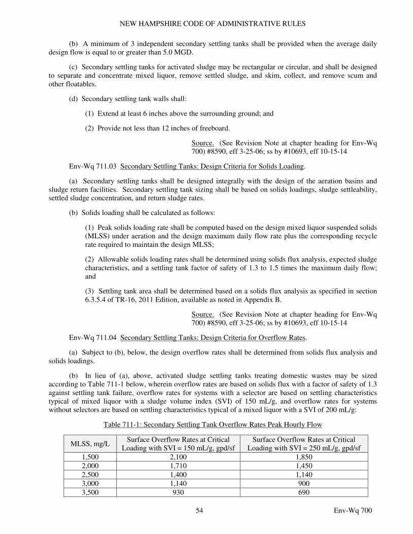
NEW HAMPSHIRE CODE OF ADMINISTRATIVE RULES
54 Env-Wq 700
(b) A minimum of 3 independent secondary settling tanks shall be provided when the average daily design flow is equal to or greater than 5.0 MGD.
(c) Secondary settling tanks for activated sludge may be rectangular or circular, and shall be designed to separate and concentrate mixed liquor, remove settled sludge, and skim, collect, and remove scum and other floatables.
(d) Secondary settling tank walls shall:
(1) Extend at least 6 inches above the surrounding ground; and
(2) Provide not less than 12 inches of freeboard.
Source. (See Revision Note at chapter heading for Env-Wq 700) #8590, eff 3-25-06; ss by #10693, eff 10-15-14
Env-Wq 711.03 Secondary Settling Tanks: Design Criteria for Solids Loading.
(a) Secondary settling tanks shall be designed integrally with the design of the aeration basins and sludge return facilities. Secondary settling tank sizing shall be based on solids loadings, sludge settleability, settled sludge concentration, and return sludge rates.
(b) Solids loading shall be calculated as follows:
(1) Peak solids loading rate shall be computed based on the design mixed liquor suspended solids (MLSS) under aeration and the design maximum daily flow rate plus the corresponding recycle rate required to maintain the design MLSS;
(2) Allowable solids loading rates shall be determined using solids flux analysis, expected sludge characteristics, and a settling tank factor of safety of 1.3 to 1.5 times the maximum daily flow; and
(3) Settling tank area shall be determined based on a solids flux analysis as specified in section 6.3.5.4 of TR-16, 2011 Edition, available as noted in Appendix B.
Source. (See Revision Note at chapter heading for Env-Wq 700) #8590, eff 3-25-06; ss by #10693, eff 10-15-14
Env-Wq 711.04 Secondary Settling Tanks: Design Criteria for Overflow Rates.
(a) Subject to (b), below, the design overflow rates shall be determined from solids flux analysis and solids loadings.
(b) In lieu of (a), above, activated sludge settling tanks treating domestic wastes may be sized according to Table 711-1 below, wherein overflow rates are based on solids flux with a factor of safety of 1.3 against settling tank failure, overflow rates for systems with a selector are based on settling characteristics typical of mixed liquor with a sludge volume index (SVI) of 150 mL/g, and overflow rates for systems without selectors are based on settling characteristics typical of a mixed liquor with a SVI of 200 mL/g:
Table 711-1: Secondary Settling Tank Overflow Rates Peak Hourly Flow
MLSS, mg/L Surface Overflow Rates at Critical
Loading with SVI = 150 mL/g, gpd/sf Surface Overflow Rates at Critical
Loading with SVI = 250 mL/g, gpd/sf
1,500 2,100 1,850
2,000 1,710 1,450
2,500 1,400 1,140
3,000 1,140 900
3,500 930 690
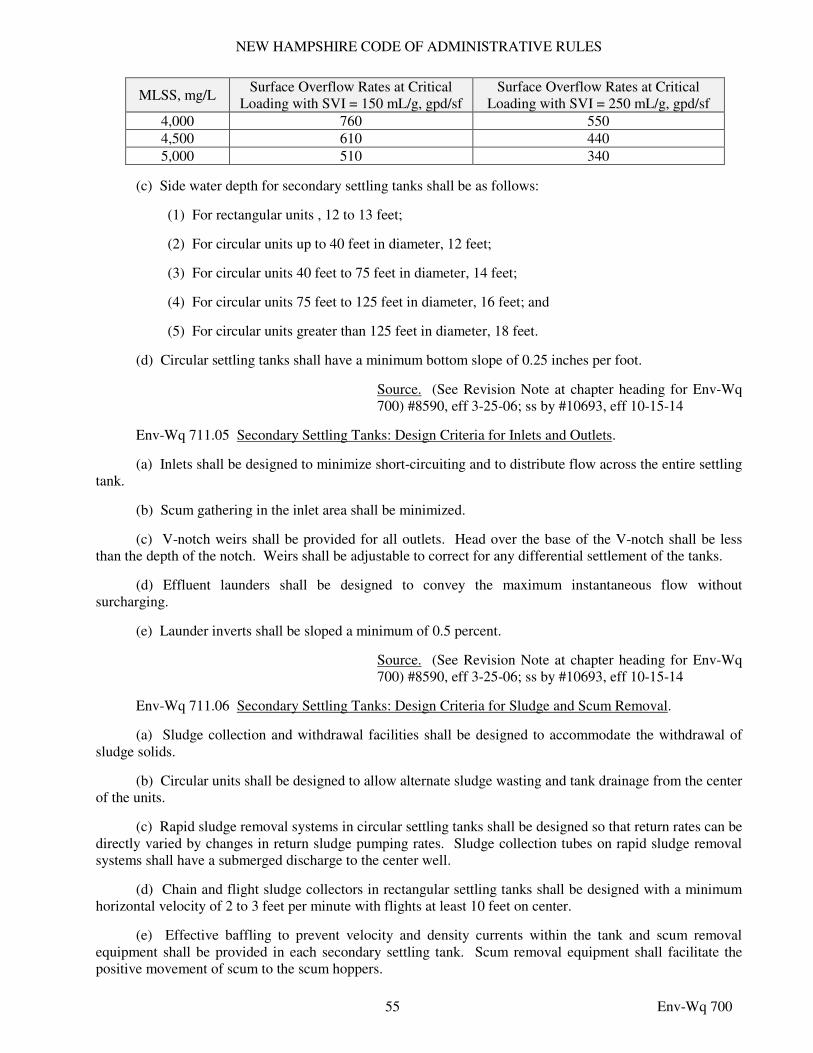
NEW HAMPSHIRE CODE OF ADMINISTRATIVE RULES
55 Env-Wq 700
MLSS, mg/L Surface Overflow Rates at Critical
Loading with SVI = 150 mL/g, gpd/sf Surface Overflow Rates at Critical
Loading with SVI = 250 mL/g, gpd/sf
4,000 760 550
4,500 610 440
5,000 510 340
(c) Side water depth for secondary settling tanks shall be as follows:
(1) For rectangular units , 12 to 13 feet;
(2) For circular units up to 40 feet in diameter, 12 feet;
(3) For circular units 40 feet to 75 feet in diameter, 14 feet;
(4) For circular units 75 feet to 125 feet in diameter, 16 feet; and
(5) For circular units greater than 125 feet in diameter, 18 feet.
(d) Circular settling tanks shall have a minimum bottom slope of 0.25 inches per foot.
Source. (See Revision Note at chapter heading for Env-Wq 700) #8590, eff 3-25-06; ss by #10693, eff 10-15-14
Env-Wq 711.05 Secondary Settling Tanks: Design Criteria for Inlets and Outlets.
(a) Inlets shall be designed to minimize short-circuiting and to distribute flow across the entire settling tank.
(b) Scum gathering in the inlet area shall be minimized.
(c) V-notch weirs shall be provided for all outlets. Head over the base of the V-notch shall be less than the depth of the notch. Weirs shall be adjustable to correct for any differential settlement of the tanks.
(d) Effluent launders shall be designed to convey the maximum instantaneous flow without surcharging.
(e) Launder inverts shall be sloped a minimum of 0.5 percent.
Source. (See Revision Note at chapter heading for Env-Wq 700) #8590, eff 3-25-06; ss by #10693, eff 10-15-14
Env-Wq 711.06 Secondary Settling Tanks: Design Criteria for Sludge and Scum Removal.
(a) Sludge collection and withdrawal facilities shall be designed to accommodate the withdrawal of sludge solids.
(b) Circular units shall be designed to allow alternate sludge wasting and tank drainage from the center of the units.
(c) Rapid sludge removal systems in circular settling tanks shall be designed so that return rates can be directly varied by changes in return sludge pumping rates. Sludge collection tubes on rapid sludge removal systems shall have a submerged discharge to the center well.
(d) Chain and flight sludge collectors in rectangular settling tanks shall be designed with a minimum horizontal velocity of 2 to 3 feet per minute with flights at least 10 feet on center.
(e) Effective baffling to prevent velocity and density currents within the tank and scum removal equipment shall be provided in each secondary settling tank. Scum removal equipment shall facilitate the positive movement of scum to the scum hoppers.
NEW HAMPSHIRE CODE OF ADMINISTRATIVE RULES
56 Env-Wq 700
(f) Scum hoppers shall have provisions to facilitate the flushing of scum from the hopper.
(g) Scum piping shall be sized for proper movement of viscous foams.
Source. (See Revision Note at chapter heading for Env-Wq 700) #8590, eff 3-25-06; ss by #10693, eff 10-15-14
Env-Wq 711.07 Secondary Settling Tanks: Design Criteria for Return Sludge.
(a) Return sludge rate capabilities shall be designed to be the greater of 100 percent of maximum month design flow or 150 percent of annual average day design flow.
(b) At least one return sludge pumping unit shall be provided for each settling tank. The maximum required return sludge capacity shall be available with the largest pumping unit out of service. Pumps may be placed on suction headers, but the arrangement and valving shall be such that any one settling tank can be isolated with a single pump.
(c) A positive suction head shall be provided for all return sludge pumps.
(d) Return sludge pumps shall have at least 3-inch suction and discharge openings.
(e) Rate of sludge return shall be varied by means of variable speed motors, drives, or timers.
(f) Return sludge suction and discharge piping shall be at least 4 inches in diameter and designed to maintain a velocity of not less than 2 feet per second when operating at average sludge return rates.
(g) Suitable devices shall be provided for sampling and measuring return sludge flow rates. Measuring devices shall totalize and record, as well as indicate flows.
(h) Capability shall be provided to return and waste sludge concurrently.
(i) Provisions shall be made for the draining and flushing of discharge lines.
Source. (See Revision Note at chapter heading for Env-Wq 700) #8590, eff 3-25-06; ss by #10693, eff 10-15-14
Env-Wq 711.08 Secondary Settling Tanks: Design Criteria for Waste Sludge.
(a) Means for measuring, sampling, and controlling the rate of waste activated sludge flow shall be provided. Measuring devices shall totalize and record, as well as indicate flows.
(b) Waste sludge shall be discharged to primary settling tanks, units for concentrating the waste sludge, storage tanks, digesters, dewatering devices, or to other means of direct removal from the plant.
(c) Waste sludge facilities shall be designed to pump the expected minimum and maximum rates of wasting.
(d) Provisions shall be made for the draining and flushing of discharge lines.
Source. (See Revision Note at chapter heading for Env-Wq 700) #8590, eff 3-25-06; ss by #10693, eff 10-15-14
PART Env-Wq 712 CHEMICAL COAGULATION FOR PRIMARY AND SECONDARY SETTLING TANKS
Env-Wq 712.01 Chemical Coagulation: Application and Mixing.
(a) Chemical coagulants shall be applied at a rate proportional to the wastewater flow.
NEW HAMPSHIRE CODE OF ADMINISTRATIVE RULES
57 Env-Wq 700
(b) Rapid and thorough mixing of the wastewater and coagulant(s) shall be provided in small tanks or pipes using:
(1) Inline blenders;
(2) Air mixers;
(3) Mechanical mixers; or
(4) Baffles. Source. (See Revision Note at chapter heading for Env-Wq 700) #8590, eff 3-25-06; ss by #10693, eff 10-15-14
Env-Wq 712.02 Chemical Coagulation: Flocculation Tanks..
(a) Flocculation following chemical coagulant mixing shall be completed in channels or tanks that meet the following requirements:
(1) At least 2 flocculation tanks or channels having a combined detention period of between 20 and 30 minutes shall be provided;
(2) Mixing shall be balanced to avoid under-mixing or over mixing such that:
a. Chemicals are completely dispersed;
b. Flocculated particles do not settle; and
c. Flocculated particles are not sheared; and
(3) Independent controls for each tank shall be provided.
(b) Settling tank design shall conform to Env-Wq 711.
(c) A means of dewatering all tanks shall be provided.
Source. (See Revision Note at chapter heading for Env-Wq 700) #8590, eff 3-25-06; ss by #10693, eff 10-15-14
Env-Wq 712.03 Chemical Coagulation: Process Impacts. Chemical coagulation shall not be used unless the owner first evaluates the following potential impacts due to chemical addition:
(a) Increased sludge production;
(b) Change in sludge thickening and dewatering characteristics;
(c) Biological phosphorous removal and denitrification capability;
(d) Sludge settling characteristics in subsequent treatment processes; and
(e) Increased operation and maintenance costs of the chemical feed system.
Source. (See Revision Note at chapter heading for Env-Wq 700) #8590, eff 3-25-06; ss by #10693, eff 10-15-14
PART Env-Wq 713 SUSPENDED GROWTH BIOLOGICAL TREATMENT
Env-Wq 713.01 Activated Sludge: General Design Requirements.
(a) The activated sludge process and its various modifications shall be used only where sewage is amenable to biological treatment.
NEW HAMPSHIRE CODE OF ADMINISTRATIVE RULES
58 Env-Wq 700
(b) WWTP design shall provide for multiple aeration tanks capable of passing peak hourly flow with one unit out of service and of meeting process requirements with all units on line.
(c) Where the WWTP design provides for all return sludge to be mixed with the raw sewage or primary effluent at one location, then the mixed liquor flow rate to each aeration unit shall be equal by means of a controlled distribution structure.
(d) All activated sludge designs shall include provisions for the control of bulking sludge and filamentous micro-organisms.
(e) Return sludge equipment shall comply with the following:
(1) The return sludge rate shall be varied by means of variable speed motors, drives, or timers. All designs shall provide for flexibility in operation. The return sludge rate shall be at least 100 percent of average annual influent design flow and sufficient to maintain design MLSS at maximum day flow rates;
(2) The maximum return sludge capacity shall be obtained with the largest pump out of service; and
(3) A method for observing, sampling, and controlling return activated sludge flow from each settling tank shall be provided.
(f) Waste sludge facilities shall comply with the following:
(1) In addition to capacity required for return sludge pumping, waste sludge pumping facilities shall be provided with a minimum capacity not less than 25 percent of design average rate of wastewater flow, or a minimum of 10 gpm, whichever is larger. Waste sludge pumps shall function satisfactorily at 0.5 percent of design annual average wastewater flow;
(2) Waste activated sludge may be discharged to the primary settling tanks, sludge digestion tanks, sludge thickening or dewatering processes, storage tank or any practical combination of these units; and
(3) A method for observing, sampling and controlling waste activated sludge flow shall be provided.
Source. (See Revision Note at chapter heading for Env-Wq 700) #8590, eff 3-25-06; ss by #10693, eff 10-15-14
Env-Wq 713.02 Activated Sludge: Aeration System Requirements.
(a) An aeration system shall be designed to:
(1) Meet maximum oxygen demand and mixing requirements and maintain process performance with the largest unit out of service;
(2) Provide for varying the amount of oxygen transferred in proportion to the load demand on the WWTP; and
(3) Have motors, gear housing, bearings, grease fittings, and other parts requiring maintenance in a location that is:
a. Accessible under routine operating conditions; and
b. Protected from submergence and spray as necessary for proper functioning.
NEW HAMPSHIRE CODE OF ADMINISTRATIVE RULES
59 Env-Wq 700
(b) The mechanism and drive unit for oxygen transfer shall be:
(1) Designed for the expected conditions in the aeration tank in terms of power performance; and
(2) Tested and certified by the aerator manufacturer.
(c) Each aeration drop leg shall be equipped with:
(1) Control valves that have indicator markings for throttling and complete shut off; and
(2) Air flow measurement capability.
(d) Air filters shall be:
(1) Provided in numbers, arrangement, and capacities to furnish at all times an air supply sufficiently free from dust to prevent damage to blowers and clogging of the diffuser system used; and
(2) Equipped with a means to measure pressure drop across the air filters.
(e) Blowers shall be located in a room that:
(1) Is separated from the office, laboratory, or control room by insulated walls to minimize blower noise, such that the noise level does not exceed 90 decibels in the blower room and does not exceed 50 decibels in the office, laboratory, or control room;
(2) Has mechanical ventilation; and
(3) Is equipped with heat recovery units if economically justified based on life cycle cost analysis.
Source. (See Revision Note at chapter heading for Env-Wq 700) #8590, eff 3-25-06; ss by #10693, eff 10-15-14
Env-Wq 713.03 Activated Sludge: Aeration System Performance Requirements.
(a) To allow for increased energy efficiency in WWTF operation through the expected life of a WWTF, the owner shall:
(1) Provide multiple blowers for diffused air systems that are sized to:
a. Meet the current facility peak aeration demand;
b. Meet turndown requirements as described in (b), below; and
c. Avoid over-aerating at current daily minimum flows;
(2) Conduct an energy evaluation to determine the optimum blower sizing, turndown, and staging;
(3) If current peak aeration demands are below peak design aeration demands, provide sufficient blower capacity to meet current peak aeration demands while ensuring that blower rooms are large enough to accommodate the blower configuration necessary to meet peak design demands;
(4) Demonstrate financial capacity or set up a reserve account to set aside the estimated money required to install additional blowers when needed to meet increased peak aeration demands; and
(5) Arrange blowers in such configuration and capacities as to meet the current peak aeration demands with the single largest unit out of service.
NEW HAMPSHIRE CODE OF ADMINISTRATIVE RULES
60 Env-Wq 700
(b) The aeration system shall be designed to:
(1) Have sufficient turndown capability that does not extend beyond the efficient operational range of the blowers, when using multiple same-sized blowers or staging with multiple varied-sized blowers;
(2) Not over-aerate or require blowing off excess air at initial year minimum flows; and
(3) Operate most efficiently at average organic loading conditions.
(c) Air requirements for a diffused air system shall be determined incorporating the following factors to be included in the design specifications or supporting documentation submitted to the department:
(1) Tank depth;
(2) Alpha factor of waste;
(3) Beta factor of waste;
(4) Certified aeration device transfer efficiency;
(5) Minimum aeration tank dissolved oxygen concentration;
(6) Mixing requirements needed to maintain solids suspension;
(7) Critical wastewater temperature; and
(8) Altitude of WWTP.
(d) Aeration requirements for carbonaceous BOD5 removal shall be based upon the maximum monthly BOD5 loading.
(e) All aeration equipment shall be capable of maintaining a minimum of 1.0 mg/L of dissolved oxygen in the mixed liquor unless a lower minimum dissolved oxygen can be justified based on process modeling.
(f) Diffused air system design shall use data derived from pilot testing or an empirical approach.
(g) When pilot facility or experimental data is not available, the design oxygen requirements shall:
(1) Be 0.8 to 1.2 pounds of oxygen per pound BOD5 removed;
(2) Be 4.57 pounds oxygen per pound design maximum day total Kjeldahl nitrogen (TKN) available for nitrification, where TKN available for nitrification is calculated as influent TKN less nitrogen required for carbonaceous growth less non-biodegradable nitrogen; and
(3) Include oxygen demands due to high BOD5 and TKN concentrations in recycle flows such as heat treatment and digester supernatants, vacuum filtrate, belt filter pressate, waste sludge recycled to primary clarifiers, and elutriates.
(h) The aeration system shall be designed to match the diurnal organic load variation while economizing on power input.
(i) The capacity of the blowers or air compressors shall be based on the site altitude and site specific minimum and maximum summer and winter temperatures.
Source. (See Revision Note at chapter heading for Env-Wq 700) #8590, eff 3-25-06; ss by #10693, eff 10-15-14
NEW HAMPSHIRE CODE OF ADMINISTRATIVE RULES
61 Env-Wq 700
Env-Wq 713.04 Activated Sludge: Protection of Aeration Systems.
(a) Electrical controls for all aeration equipment shall be protected from the elements.
(b) Where extended cold weather conditions occur, the aerator mechanism and associated structure shall be protected from freezing due to ice formation from splashing.
Source. (See Revision Note at chapter heading for Env-Wq 700) #8590, eff 3-25-06; ss by #10693, eff 10-15-14
Env-Wq 713.05 Activated Sludge: Aeration Tank Design.
(a) The aeration tank size for any particular adaptation of the activated sludge process shall be determined by:
(1) Pilot studies; or
(2) Rational calculations based primarily on solids retention time (SRT) and MLSS levels while also considering other factors, including but not limited to capacity, wastewater characterization relevant to the proposed process, diurnal load variations, degree of treatment required, pH, temperature, alkalinity, and dissolved oxygen.
(b) The engineer shall furnish aeration tank sizing calculations to the department with the engineering design documents.
(c) Aeration tank volume requirements for nitrification shall be based on maximum monthly loading.
(d) The dimensions of each independent mixed liquor aeration tank or return sludge re-aeration tank shall be such as to maintain effective mixing and use of air, provided that liquid depths shall be not less than 12 feet nor more than 25 feet.
(e) Inlets and outlets for each aeration tank unit shall be equipped with valves, gates, stop plates, weirs, or other devices to permit flow control to any unit and to maintain a constant liquid level while preventing short-circuiting through the tank.
(f) Channels and pipes carrying liquids with solids in suspension shall be designed to maintain self-cleansing velocities or shall be agitated to keep such solids in suspension at all rates of flow within the design limits.
(g) Piping shall allow flexible operation sequence of tanks and returned sludge inlets.
(h) Aeration tank freeboard shall be:
(1) Not less than 3 feet if a mechanical surface aerator is used; and
(2) Not less than 18 inches in all other aeration tanks.
(i) Froth and foam control or removal shall be provided at the aeration tanks.
(j) Thorough mixing of the mixed liquor to prevent deposition of solids at any point in the tanks shall be provided.
(k) Aeration tanks shall have probes to monitor dissolved oxygen in place, to control power consumption and match oxygen demand with oxygen supply.
(l) Diffusers shall be spaced to satisfy oxygenation requirements through the length of the channel or tank, and to facilitate spacing adjustments without major revisions to the existing air header piping.
NEW HAMPSHIRE CODE OF ADMINISTRATIVE RULES
62 Env-Wq 700
Source. (See Revision Note at chapter heading for Env-Wq 700) #8590, eff 3-25-06; ss by #10693, eff 10-15-14
Env-Wq 713.06 Oxidation Ditches.
(a) Oxidation ditch design shall be based on experience at other comparable facilities and meet the applicable requirements of Env-Wq 713.01 through Env-Wq 713.05 except as modified in this section.
(b) Oxidation ditch design shall comply with the following requirements:
(1) Ditches shall be interconnected such that either ditch can be taken out of service temporarily and the ditches can be operated either in series or in parallel; and
(2) Minimum horizontal velocity shall be not less than one foot per second.
Source. (See Revision Note at chapter heading for Env-Wq 700) #8590, eff 3-25-06; ss by #10693, eff 10-15-14
Env-Wq 713.07 Sequencing Batch Reactors.
(a) Sequencing batch reactor (SBR) design shall be based on experience at comparable facilities and meet the applicable requirements of Env-Wq 713.01 through Env-Wq 713.05 except as modified in this section.
(b) SBRs shall be designed and constructed to allow for static fill, mixed fill, and aerated fill to allow for operational flexibility.
(c) More than 2 tanks shall be provided, unless one of the following is provided:
(1) An influent flow equalization tank sized to hold a minimum of 2 design capacity decantable volumes; or
(2) Provisions to allow SBR tanks to operate in a continuous flow-through mode during emergency operations.
(d) System sizing shall be based on aerated SRT.
(e) System reliability with any single SBR tank out of service and the instantaneous flow delivery shall be evaluated in the design of decanter weirs and approach velocities.
(f) The decanter shall not create a vortex or take in floatables or sludge.
(g) Scum removal shall be provided.
(h) The SBR design shall include in-place dewatering capability and provisions for transferring mixed liquor between the SBR tanks.
(i) Each SBR tank shall be capable of wasting sludge during each cycle.
(j) If blowers are provided, blowers shall meet the requirements of Env-Wq 713.02 through 713.05.
(k) Mechanical mixing independent of aeration shall be provided for all systems where biological phosphorous removal or denitrification is required, with mixing equipment sized to thoroughly mix the entire basin from a settled condition within 3 minutes without aeration.
(l) Post-SBR tank flow equalization shall be provided to equalize flow variations and designed to meet the following criteria:
(1) Hold a minimum of one design capacity decantable volume;
NEW HAMPSHIRE CODE OF ADMINISTRATIVE RULES
63 Env-Wq 700
(2) Provide a means to return the decanted effluent to the headworks for additional treatment; and
(3) Provide a means to remove solids from the tank bottom.
(m) An automatic process control having an uninterruptible power supply with electrical surge protection shall be provided.
(n) Manual override shall be provided in addition to automatic process control. Both automatic and manual controls shall allow independent operation of each tank.
(o) Controls shall allow at least 20 minutes of settling between the react and decant phases.
Source. (See Revision Note at chapter heading for Env-Wq 700) #8590, eff 3-25-06; ss by #10693, eff 10-15-14
Env-Wq 713.08 Aerated Lagoon Design: General Requirements.
(a) To develop final design parameters for aerated lagoons, actual operating data shall be used, if available.
(b) If actual data is not available, the aerated lagoon system design for minimum detention time in days (t) shall be estimated for each aerated cell by dividing the percent of BOD5 to be removed in the aerated lagoon (E) by the product of 2.3 multiplied by the reaction rate coefficient for an aerated lagoon in base 10 (k1) multiplied by the result of subtracting E from 100, as shown in the following formula:
t = E
2.3k1(100-E)
(c) For purposes of (b), above, the reaction rate coefficient (k1) shall be as follows:
(1) For domestic wastewater, 0.12/day at 68°F, equivalent to 20°C, and 0.06/day at 34°F, equivalent to 1°C, unless data is available to indicate a more appropriate k1 value for the specific site;
(2) For domestic wastewater that includes some industrial wastes, other wastes, and partially treated wastewater, as determined experimentally for various conditions which might be encountered in the aerated ponds; and
(3) Conversion of the reaction rate coefficient to other temperatures shall be made based on experimental data.
(d) There shall be a minimum of 3 separate cells. Baffles may be used to create up to 2 cells in one lagoon.
(e) All aerated lagoon systems shall be designed with piping flexibility to allow isolation of any cell without affecting the transfer and discharge capabilities of the total system.
(f) The ability to discharge influent waste load to a minimum of 2 cells or all primary cells in the system shall be provided.
(g) The shape of all lagoons shall be such that there are no narrow or elongated portions. Lagoons shall be round, square, trapezoidal, or rectangular with the length not exceeding 3 times the width.
(h) Additional lagoon volume of at least 20 percent shall be included for sludge storage and ice cover.
Source. (See Revision Note at chapter heading for Env-Wq 700) #8590, eff 3-25-06; ss by #10693, eff 10-15-14
NEW HAMPSHIRE CODE OF ADMINISTRATIVE RULES
64 Env-Wq 700
Env-Wq 713.09 Aerated Lagoon Design: Aeration Equipment. In addition to the applicable portions of Env-Wq 713.02 through Env-Wq 713.05, aerated lagoon aeration equipment shall meet the following requirements:
(a) Aeration shall be of the diffused or mechanical mixing type; and
(b) For diffused air systems:
(1) Multiple blower units shall be provided and sized such that, with any unit out of service, the remaining units are capable of supplying all aeration needs;
(2) Means shall be provided for regulating, measuring, and recording the flow of air to the lagoons;
(3) Air diffusion piping headers and piping supports shall be corrosion-resistant with a durability for the anticipated life of the WWTP; and
(4) Ductile iron pipe headers or piping shall not be cement lined.
Source. (See Revision Note at chapter heading for Env-Wq 700) #8590, eff 3-25-06; ss by #10693, eff 10-15-14
Env-Wq 713.10 Aerated Lagoon Design: Inlet and Outlet Piping.
(a) Aerated lagoon piping systems shall be designed to avoid areas of stagnation, short circuiting, solids deposition, or dead zones in the lagoons.
(b) Inlet piping shall be located 1/5 to 1/3 of the total water depth from the lagoon bottom, but not less than 2 feet above the bottom of the lagoon bottom. On lagoons 150 or more feet wide, multiple inlets shall be used to enhance distribution of the influent flow.
(c) Outlets shall be designed to provide multiple draw-off levels. Draw-off capability shall be provided over as much of the operating depth as feasible.
(d) All aerated cells shall have influent lines which distribute the load within the mixing zone of the aeration equipment to minimize short-circuiting.
(e) The influent line shall discharge vertically on to a concrete apron no smaller than 4 square feet to prevent scouring and erosion.
Source. (See Revision Note at chapter heading for Env-Wq 700) #8590, eff 3-25-06; ss by #10693, eff 10-15-14
Env-Wq 713.11 Aerated Lagoon Design: Distribution and Interconnection Piping.
(a) Self-cleaning velocities shall be present in aerated lagoon distribution piping.
(b) To prevent erosion due to discharge at the termination of distribution and interconnecting piping, the piping shall discharge vertically on a concrete apron 4 feet square, as a minimum.
(c) Interconnecting piping shall discharge vertically near the lagoon bottom and at the dike, thereby reducing erosion effects.
(d) Piping shall be ductile iron, stainless steel, HDPE, or SDR 35 PVC.
(e) Distribution and interconnection piping clean-outs shall be provided.
(f) Seepage collars shall be provided around any pipes penetrating the dike. The collars shall extend a minimum of 2 feet radially from the pipe.
NEW HAMPSHIRE CODE OF ADMINISTRATIVE RULES
65 Env-Wq 700
(g) Flow distribution structures shall be designed to effectively split hydraulic and organic loads equally to primary cells.
(h) All primary cells shall have individual influent lines that terminate approximately at the mid-point of the cell width and at approximately 2/3 of the cell length away from the outlet structure to minimize short-circuiting.
Source. (See Revision Note at chapter heading for Env-Wq 700) #8590, eff 3-25-06; ss by #10693, eff 10-15-14
Env-Wq 713.12 Aerated Lagoon Design: Overflow Structures.
(a) Intakes for aerated lagoon overflow structures shall be located a minimum of 10 feet from the toe of the dike and 2 feet below the top of the liner.
(b) Weirs or gates shall be of lightweight, corrosion-resistant material such as aluminum or fiberglass.
(c) Scum baffle mechanisms shall be provided.
(d) Provision shall be made for draining the lagoons.
(e) Location of draw off pipes shall minimize erosion effects.
(f) To prevent overtopping the dikes, emergency overflow between cells shall be provided.
(g) Hydraulic capacity for discharge structures and piping shall allow for a minimum of 250 percent of the design maximum day flow of the system.
Source. (See Revision Note at chapter heading for Env-Wq 700) #8590, eff 3-25-06; ss by #10693, eff 10-15-14
Env-Wq 713.13 Aerated Lagoon Design: Embankments, Dikes & Bottom.
(a) Aerated lagoon dikes, embankments, and bottoms shall form a stable structure impervious to seepage of lagoon liquid.
(b) The minimum top width of a dike or embankment shall be 8 feet to permit access by maintenance vehicles.
(c) Aerated lagoon dikes and embankments shall have inner faces not steeper than a 3:1 slope nor shallower than a 4:1 slope, and outer faces not steeper than a 3:1 slope.
(d) Aerated lagoons shall be designed such that surface water shall not flow or drain into the lagoons.
(e) Aerated lagoon dikes shall be designed to provide a minimum of 3 feet of freeboard above normal lagoon water surface elevation.
(f) For aerated lagoon systems, the design water depth shall range from a minimum of 10 feet to a maximum of 20 feet.
(g) Seeding and erosion control shall be as follows:
(1) Outside slopes shall be seeded with perennial type, slow growing, spreading grasses that minimize erosion and can be mowed; and
(2) Inside slopes shall have rip rap or comparable material of suitable size and weight installed from the top of the dike to at least one foot below normal lagoon operating level to protect the slopes from erosion and wave action.
NEW HAMPSHIRE CODE OF ADMINISTRATIVE RULES
66 Env-Wq 700
(h) The lagoon bottom shall be smooth and level at all points. Finished elevations shall vary not more than 3 inches from the average elevation of the bottom.
(i) A minimum separation of 4 feet between the bottom of the pond and the maximum ground water elevation shall be provided unless an effective underdrain system is provided.
(j) A minimum separation of 2 feet between the liner bottom at the bottom of the lagoon and any bedrock formation shall be provided.
Source. (See Revision Note at chapter heading for Env-Wq 700) #8590, eff 3-25-06; ss by #10693, eff 10-15-14
Env-Wq 713.14 Aerated Lagoon Design: Groundwater Pollution and Soil Formation.
(a) Contamination of groundwater by transmission through the soil or overflows that can cause a health hazard in water supplies or cause ground or surface water quality violations shall be prohibited.
(b) Liquid loss through the lagoon dikes and bottom shall be prohibited.
(c) Impervious membrane liners shall be installed in all new lagoons.
(d) Lined lagoons shall be permitted as required by Env-Or 700.
Source. (See Revision Note at chapter heading for Env-Wq 700) #8590, eff 3-25-06; ss by #10693, eff 10-15-14
Env-Wq 713.15 Aerated Lagoon Design: Area Control.
(a) Fencing shall surround the entire site with locking access gates for vehicles and equipment. Fencing shall not obstruct maintenance vehicle traffic on top of the dikes.
(b) An all-weather access road shall be provided to the pond site to allow year-round maintenance of the facility.
(c) Warning signs advising against trespassing and showing the nature of the facility shall be posted along the fence as follows:
(1) At least one sign on each side of the site; and
(2) At least one sign for every 500 feet of the fence’s perimeter.
Source. (See Revision Note at chapter heading for Env-Wq 700) #8590, eff 3-25-06; ss by #10693, eff 10-15-14
PART Env-Wq 714 FIXED FILM BIOLOGICAL TREATMENT
Env-Wq 714.01 Trickling Filters: General Requirements.
(a) Biological trickling filters shall only be used when the sewage is amenable to treatment by aerobic biologic processes.
(b) Trickling filters shall be preceded by effective settling tanks equipped with scum collecting devices or other suitable pretreatment facilities and followed by secondary settling tanks in accordance with Env-Wq 711.02 through Env-Wq 711.08.
(c) Trickling filters shall be designed either as low-rate or high-rate filters which incorporate recirculation. Reduction in BOD5 in primary settling tanks shall not exceed 35 percent for filter design criteria.
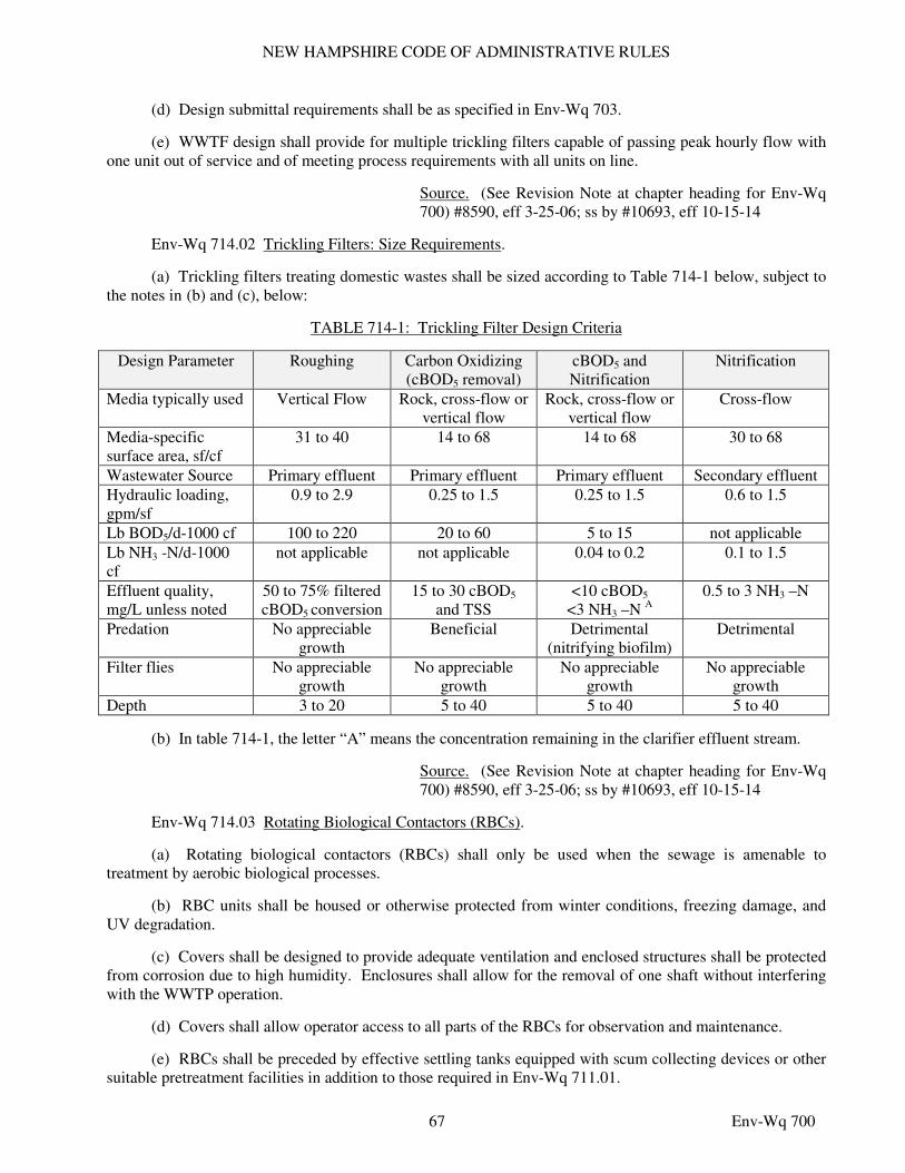
NEW HAMPSHIRE CODE OF ADMINISTRATIVE RULES
67 Env-Wq 700
(d) Design submittal requirements shall be as specified in Env-Wq 703.
(e) WWTF design shall provide for multiple trickling filters capable of passing peak hourly flow with one unit out of service and of meeting process requirements with all units on line.
Source. (See Revision Note at chapter heading for Env-Wq 700) #8590, eff 3-25-06; ss by #10693, eff 10-15-14
Env-Wq 714.02 Trickling Filters: Size Requirements.
(a) Trickling filters treating domestic wastes shall be sized according to Table 714-1 below, subject to the notes in (b) and (c), below:
TABLE 714-1: Trickling Filter Design Criteria
Design Parameter Roughing Carbon Oxidizing (cBOD5 removal)
cBOD5 and Nitrification
Nitrification
Media typically used Vertical Flow Rock, cross-flow or vertical flow
Rock, cross-flow or vertical flow
Cross-flow
Media-specific surface area, sf/cf
31 to 40 14 to 68 14 to 68 30 to 68
Wastewater Source Primary effluent Primary effluent Primary effluent Secondary effluent
Hydraulic loading, gpm/sf
0.9 to 2.9 0.25 to 1.5 0.25 to 1.5 0.6 to 1.5
Lb BOD5/d-1000 cf 100 to 220 20 to 60 5 to 15 not applicable
Lb NH3 -N/d-1000 cf
not applicable not applicable 0.04 to 0.2 0.1 to 1.5
Effluent quality, mg/L unless noted
50 to 75% filtered cBOD5 conversion
15 to 30 cBOD5 and TSS
<10 cBOD5
<3 NH3 –N A 0.5 to 3 NH3 –N
Predation No appreciable growth
Beneficial Detrimental (nitrifying biofilm)
Detrimental
Filter flies No appreciable growth
No appreciable growth
No appreciable growth
No appreciable growth
Depth 3 to 20 5 to 40 5 to 40 5 to 40
(b) In table 714-1, the letter “A” means the concentration remaining in the clarifier effluent stream.
Source. (See Revision Note at chapter heading for Env-Wq 700) #8590, eff 3-25-06; ss by #10693, eff 10-15-14
Env-Wq 714.03 Rotating Biological Contactors (RBCs).
(a) Rotating biological contactors (RBCs) shall only be used when the sewage is amenable to treatment by aerobic biological processes.
(b) RBC units shall be housed or otherwise protected from winter conditions, freezing damage, and UV degradation.
(c) Covers shall be designed to provide adequate ventilation and enclosed structures shall be protected from corrosion due to high humidity. Enclosures shall allow for the removal of one shaft without interfering with the WWTP operation.
(d) Covers shall allow operator access to all parts of the RBCs for observation and maintenance.
(e) RBCs shall be preceded by effective settling tanks equipped with scum collecting devices or other suitable pretreatment facilities in addition to those required in Env-Wq 711.01.
NEW HAMPSHIRE CODE OF ADMINISTRATIVE RULES
68 Env-Wq 700
(f) Multiple trains shall be furnished for flexible operation and stage bypassing.
(g) Flow control to RBC tanks shall be by splitter boxes and weirs.
(h) Buildings housing RBC processes shall have ventilation of at least 6 air changes per hour.
(i) Electrical system components, panels, light fixtures, motors, and control centers shall be watertight and corrosion resistant.
(j) Shafts and media shall be designed for an operational life of 20 years.
(k) RBC units shall be sized in accordance with the following:
(1) Organic loading to the first stage of the RBC system shall not exceed 6 to 8 pounds of BOD5/1,000 square feet/day or 2.5 to 4 pounds of soluble BOD5/1,000 cubic feet/day; and
(2) Maximum bearing capacities for the shafts shall be specified based on the expected film thickness, the capacity to strip biofilm, and an adequate margin of safety. Load cells shall be provided for all shafts to monitor loadings.
(l) Media shall be constructed to allow portions to be removed for cleaning and replacement without requiring the entire shaft assembly to be removed from the tanks.
(m) Adequate flexibility in process operation shall be provided by including one or more of the following in the design:
(1) Variable rotational speeds in the first and second stages, including speed reversal to remove excess biofilm;
(2) Removable baffles between all stages in contoured basins to avoid dead spaces;
(3) Positive influent flow control to each unit or flow train, including positively-controlled alternate flow distribution systems such as step feed;
(4) Positive air flow metering and control to each shaft when supplemental air or motor driven units are used; or
(5) Recirculation of secondary effluent.
Source. (See Revision Note at chapter heading for Env-Wq 700) #8590, eff 3-25-06; ss by #10693, eff 10-15-14
PART Env-Wq 715 DISINFECTION
Env-Wq 715.01 Disinfection Requirement. All wastewater shall be disinfected prior to discharge when the discharge permit includes bacteria limitations.
Source. (See Revision Note at chapter heading for Env-Wq 700) #8590, eff 3-25-06; ss by #10693, eff 10-15-14
Env-Wq 715.02 Methods. The following disinfectant methods shall be allowed for wastewater discharges:
(a) Sodium hypochlorite or calcium hypochlorite;
(b) Ultraviolet irradiation; or
NEW HAMPSHIRE CODE OF ADMINISTRATIVE RULES
69 Env-Wq 700
(c) Other performance-based innovative technologies that are shown to be cost-effective and able to meet the disinfection requirements of the discharge permit.
Source. (See Revision Note at chapter heading for Env-Wq 700) #8590, eff 3-25-06; ss by #10693, eff 10-15-14
Env-Wq 715.03 Hypochlorite Systems.
(a) Hypochlorite solution feed equipment shall incorporate effluent flow proportional control systems or effluent flow proportional combined with demand proportional control systems.
(b) Hypochlorite feeders shall be of the positive displacement type.
(c) Hypochlorite solution storage shall be of sufficient volume to provide for dosing at the anticipated maximum dose rate at design annual average flow for 15 days.
(d) Hypochlorite solution feed systems shall be capable of dosing at the anticipated maximum dose rate at maximum flows, with turndown capabilities to accommodate minimum flows.
(e) A redundant hypochlorite feed pump shall be provided.
(f) Rooms housing hypochlorite feed equipment and appurtenances shall be mechanically ventilated to provide at least 6 air changes per hour.
(g) Mechanical ventilation systems shall draw from floor level.
(h) Application of hypochlorite shall be as follows:
(1) Mixing of the disinfectant at the point of injection before the contact tank shall be provided using hydraulic or mechanical means; and
(2) A minimum contact period of 15 minutes at peak hourly flow or maximum rate of pumping shall be provided.
(i) Contact tank design shall be as follows:
(1) The contact tank shall have a minimum of 2 separate chambers;
(2) The contact tank shall be configured to reduce short-circuiting of flows;
(3) A minimum 40:1 length to width ratio of the contact passage shall be provided;
(4) A scum baffle and scum removal piping shall be provided at the effluent end of the tank;
(5) Provisions shall be made for draining and washing down the contact tank; and
(6) Drainage flow shall be returned to the treatment process.
(j) Facilities shall be provided for obtaining samples, either grab or continuous as stipulated by permit, of the disinfected effluent after contact.
(k) Equipment for residual chlorine testing and recording shall be provided, which is capable of measuring in the range from 10 parts per million to the lower limit established by permit.
(l) Alarm systems shall be provided for:
(1) Low hypochlorite storage tank level;
(2) High hypochlorite storage tank level; and
NEW HAMPSHIRE CODE OF ADMINISTRATIVE RULES
70 Env-Wq 700
(3) Failure of the hypochlorite feed system.
(m) Hypochlorite solution, storage tanks, pumps and feed lines shall be protected from freezing.
Source. (See Revision Note at chapter heading for Env-Wq 700) #8590, eff 3-25-06; ss by #10693, eff 10-15-14
Env-Wq 715.04 Dechlorination Systems.
(a) Dechlorination to reduce free and combined chlorine residuals in WWTP effluent, if required by permit, shall be by use of sulfite salt solutions.
(b) Dechlorination systems shall:
(1) Be sized to chemically neutralize 5 parts per million total residual chlorine at all flows;
(2) Be of the positive displacement type;
(3) Include storage of sufficient volume to provide for dosing at the anticipated maximum dose rate at design annual average flow for 15 days;
(4) Include a redundant dechlorination feed pump;
(5) Provide thorough hydraulic or mechanical mixing at the point of sulfite injection;
(6) Provide a flow proportional feed forward control system;
(7) Provide a sampling point for compliance monitoring after dechlorination;
(8) Provide an alarm system to actuate upon failure of the dechlorination feed system;
(9) Have chemical storage tanks equipped with a mechanical mixing device to keep the chemical solution completely mixed, and
(10) Have dechlorination solutions, storage tanks, pumps and feed lines protected from freezing.
Source. (See Revision Note at chapter heading for Env-Wq 700) #8590, eff 3-25-06; ss by #10693, eff 10-15-14
Env-Wq 715.05 Ultraviolet (UV) Irradiation Systems.
(a) An initial assessment of the capabilities of UV disinfection shall be made through transmittance testing to demonstrate the absence of interfering constituents.
(b) UV disinfection systems shall deliver UV radiation dosages as demonstrated by plant-specific pilot testing to be effective in maintaining compliance with the bacteriological limits of the discharge permit.
(c) The UV disinfection system shall consist of multiple banks of lamp modules capable of disinfecting peak hourly flows with one bank out of service.
(d) Provisions shall be made for easy removal and inspection of UV lamps for maintenance or replacement without draining the UV channel.
(e) Provisions shall be made for cleaning the lamp sleeves.
(f) Provisions shall be made for draining and cleaning the UV channel while maintaining adequate disinfection or storing forward flow.
NEW HAMPSHIRE CODE OF ADMINISTRATIVE RULES
71 Env-Wq 700
(g) For facilities with a design average flow in excess of 100,000 gpd, UV system controls shall enable UV disinfection system output to be varied in proportion to the effluent flow, percent transmittance, or a combination of both parameters in order to disinfect over the range of water quality conditions.
(h) Warning alarms and automatic shutdown shall be provided. Lamp output through the contact area shall be monitored, and a low dosage warning signal shall be furnished.
(i) The UV system shall be connected to the WWTP’s standby power source and shall be equipped with an uninterruptible power supply to power unit during transfers to and from the standby power source.
(j) The UV system shall not produce any dangerous levels of ozone.
(k) The UV system operating area shall be ventilated.
(l) The UV system shall be fully enclosed in a building for year-round operation.
(m) Provisions for measuring UV transmittance shall be provided.
Source. (See Revision Note at chapter heading for Env-Wq 700) #8590, eff 3-25-06; ss by #10693, eff 10-15-14
PART Env-Wq 716 SLUDGE HANDLING AND DISPOSAL
Env-Wq 716.01 Sludge Stabilization Methods.
(a) Liquid or solid phase sludge stabilization in accordance with this part shall be required prior to the beneficial use of sludge and scum in accordance with Env-Wq 800 and 40 CFR Part 503.
(b) Acceptable solid phase sludge stabilization processes after dewatering shall be based on the types and quantities of wastewater, septage, and other waste streams to be accepted, as applicable, and may include one or more of the following:
(1) Composting;
(2) Heat drying;
(3) Pasteurization;
(4) Air-drying; and
(5) Lime stabilization.
(c) Acceptable liquid phase sludge stabilization processes shall be as follows:
(1) Anaerobic digestion, including mesophilic and thermophilic processes;
(2) Aerobic digestion;
(3) Liquid lime stabilization; and
(d) Other processes approved under Env-Wq 800 and 40 CFR Part 503.
Source. (See Revision Note at chapter heading for Env-Wq 700) #8590, eff 3-25-06; ss by #10693, eff 10-15-14
Env-Wq 716.02 Sludge Stabilization Design Requirements.
(a) Sludge stabilization processes shall be designed to meet the requirements of Env-Wq 800 for pathogen and vector attraction reduction for Class A or Class B biosolids.
NEW HAMPSHIRE CODE OF ADMINISTRATIVE RULES
72 Env-Wq 700
(b) Proprietary processes for which design criteria are primarily provided by equipment manufacturers to accommodate their equipment and design concepts shall be supported by a detailed basis of design which cites existing successfully-operating facilities with similar solids types and similar capacities with similar design criteria.
(c) Access for maintenance, repair, and inspection shall be provided for all stabilization process equipment and related tankage.
(d) Safety devices shall include:
(1) Automatic shutdown upon critical system component malfunction;
(2) Alarm systems for equipment failure; and
(3) Alarm systems for hazardous conditions.
(e) Redundancy of equipment and tankage or storage shall be provided so that the solids stabilization process will continue to be operable in the event of a failure of any single system component.
(f) Odor control technology and practices shall be provided to control odors generated from the solids handling processes to minimize the impact of odors outside the facility property boundaries.
(g) A written contingency plan that describes how solids processing and sludge removal will continue in the event of stabilization process equipment failure shall be submitted for all proposed stabilization processes.
Source. (See Revision Note at chapter heading for Env-Wq 700) #8590, eff 3-25-06; ss by #10693, eff 10-15-14
Env-Wq 716.03 Sludge Handling and Disposal Design Criteria. A complete summary of the proposed design criteria for solids handling processes shall be provided in the basis of design, including:
(a) Intended disposal methods;
(b) Projected design year loadings;
(c) A detailed description and analysis of the design criteria used to select an alternative design, if applicable;
(d) Projected performance; and
(e) Proposed odor control technology.
Source. (See Revision Note at chapter heading for Env-Wq 700) #8590, eff 3-25-06; ss by #10693, eff 10-15-14
Env-Wq 716.04 Sludge Grinder Pumps.
(a) Sludge grinder pumps shall be installed prior to sludge processing equipment that would be adversely affected by large solids.
(b) Grinders shall be installed on the suction side of the pump to prevent clogging.
Source. (See Revision Note at chapter heading for Env-Wq 700) #8590, eff 3-25-06; ss by #10693, eff 10-15-14
NEW HAMPSHIRE CODE OF ADMINISTRATIVE RULES
73 Env-Wq 700
Env-Wq 716.05 Sludge Storage Requirements.
(a) Sludge storage facilities shall be designed to control odors so that odors do not create a nuisance at the property boundary.
(b) For facilities that transport sludge to another facility as the means of disposal, storage capacity shall be designed to accommodate at least 5 days of sludge production based on maximum month design sludge generation rate.
(c) Storage areas shall be designed to minimize tracking of dewatered cake on-site and eliminate runoff from the dewatered cake storage area to other portions of the site or off-site.
Source. (See Revision Note at chapter heading for Env-Wq 700) #8590, eff 3-25-06; ss by #10693, eff 10-15-14
Env-Wq 716.06 Anaerobic Sludge Digestion: Tanks.
(a) Multiple tanks piped to operate both in series and in parallel shall be provided for the anaerobic sludge digestion process unless alternate methods of sludge stabilization and emergency storage are provided.
(b) Tank capacity shall be determined based on:
(1) Volume of sludge added;
(2) Percent solids and character;
(3) Temperature to be maintained in the digesters;
(4) Mixing to be obtained;
(5) Degree of volatile solids reduction required. For high rate digestion, the volatile solids loading shall not exceed 0.16 pounds per cubic foot per day; and
(6) Allowance for grit accumulation.
(c) If the digesters will serve as supernatant separation tanks, the tank sidewater depth shall:
(1) Be a minimum of 20 feet; and
(2) Allow for the formation of supernatant liquor.
(d) Digester tanks shall be covered.
(e) Sludge mixing systems shall be capable of:
(1) Mixing sludge to a uniform consistency; and
(2) Controlling foam.
(f) Digestion tanks shall incorporate the following features to facilitate emptying, cleaning, and maintenance:
(1) The tank bottom shall slope to drain toward the withdrawal pipe at a slope of not less than 3 inches per foot unless mechanical sludge collection is employed and then slope of not less than one inch per foot;
(2) At least 2 access manholes having 36-inch diameters and one gas dome shall be provided in the top of the tank with stairway access to the manholes;
NEW HAMPSHIRE CODE OF ADMINISTRATIVE RULES
74 Env-Wq 700
(3) At least one additional access manhole shall be provided and shall be large enough to permit the mechanical removal of grit and sand;
(4) Non-sparking tools, rubber-soled shoes, safety harness, gas detectors for flammable and toxic gases, and gas masks of the hose or oxygen helmet type shall be specified for use in the tanks; and
(5) Alarms shall be installed to warn of:
a. Any drop of the liquid level below minimum operating elevation; or
b. Low pressure in the space above the liquid level.
(g) Digestion tanks shall incorporate the following inlet and draw-off features:
(1) Multiple sludge inlets and draw-offs ports and, where used, multiple recirculation suction and discharge points, to facilitate flexible operation and effective mixing of the digester contents shall be provided unless adequate mechanical mixing facilities are provided within the digester;
(2) One inlet shall discharge above the liquid level and be located at approximately the center of the tank to assist in scum breakup;
(3) The inlet discharge shall be isolated from the gas draw-off point of the cover; and
(4) Raw sludge inlet discharge points shall be located so as to minimize short-circuiting.
Source. (See Revision Note at chapter heading for Env-Wq 700) #8590, eff 3-25-06; ss by #10693, eff 10-15-14
Env-Wq 716.07 Anaerobic Sludge Digestion: Piping and Appurtenances.
(a) Digester systems shall be equipped with thermometers to monitor temperatures of the sludge, hot water feed, hot water return and boiler water.
(b) All portions of the gas system, including the space above the tank liquor, storage facilities and piping, shall be designed such that under normal operating conditions, including sludge withdrawal, the gas shall be maintained under positive pressure.
(c) All occupied enclosed areas where gas leakage might occur shall be mechanically ventilated in accordance with the NFPA as incorporated by reference in the state fire code in Saf-C 6000.
(d) All gas metering, compressor, control and appurtenant equipment shall be located in a separate room with only an outside entrance and equipped with a hazardous gas detection alarm system.
(e) Pressure and vacuum relief valves and flame traps together with automatic safety shut-off valves shall be provided.
(f) The gas piping system shall be:
(1) Protected from freezing;
(2) Sloped 1-2 percent to drain to condensation traps at all low points;
(3) Equipped with either float-controlled or U-tube water seal type condensate traps;
(4) Corrosion resistant; and
(5) Designed to maintain digester gas velocities less than 12 feet per second.
NEW HAMPSHIRE CODE OF ADMINISTRATIVE RULES
75 Env-Wq 700
(g) Gas burning boilers and engines shall be:
(1) Located in ventilated rooms at ground level;
(2) Separated from the digester gallery; and
(3) Equipped with flame traps and pressure relief valves at a minimum.
(h) Cogeneration system design parameters shall include:
(1) Volume of gas produced by digesters;
(2) Digester gas energy value in BTUs/cubic foot;
(3) Gas composition;
(4) Gas storage capability; and
(5) Gas pretreatment requirements.
(i) Electrical systems and equipment shall comply with the NEC requirements adopted by reference in the state building code pursuant to RSA 155-A:1, IV, for the installed locations.
(j) Digester pipe galleries shall be designed in accordance with the NFPA as incorporated by reference in the state fire code in Saf-C 6000.
(k) Waste gas burners shall be accessible and located:
(1) At least 25 feet away from any plant structure when placed at ground level; or
(2) On the roof of a control building if they are:
a. Removed from the tank; and
b. High enough that flames will not be blown within 10 feet of the roof surface.
(l) A gas meter with by-pass shall be provided to measure total gas production, per-tank gas production, and flared gas.
(m) Digestion tanks shall be insulated to minimize heat loss.
(n) Sludge shall be heated by circulating the sludge through external heaters and piping shall be designed to provide for the preheating of feed sludge before introduction to the digesters. Provisions shall be made in the layout of the piping and valving to facilitate cleaning of these lines.
(o) Where digestion gas is used for heating, an auxiliary fuel shall be provided.
(p) For tanks where supernatant is withdrawn from the digester, digester supernatant piping shall be:
(1) Not less than 6 inches in diameter;
(2) Arranged so that withdrawal can be made from 3 or more levels in the tank; and
(3) Equipped with an unvalved emergency overflow designed to prevent sludge discharge to the gas system that will convey digester overflow to the WWTP headworks, the aeration process, or to another liquid sludge storage facility and that has provisions for monitoring overflows and sounding an alarm if and when an overflow occurs.
(q) Provision shall be made for sampling at each supernatant draw-off level.
NEW HAMPSHIRE CODE OF ADMINISTRATIVE RULES
76 Env-Wq 700
(r) High pressure backwash facilities shall be provided for the piping system.
Source. (See Revision Note at chapter heading for Env-Wq 700) #8590, eff 3-25-06; ss by #10693, eff 10-15-14
Env-Wq 716.08 Aerobic Sludge Digestion.
(a) Aerobic sludge digestion shall be accomplished in a tank or tanks designed to provide effective air mixing, reduction of the organic matter, and sludge concentration under controlled conditions.
(b) Tank capacities shall be based on the quantity of sludge produced and sludge characteristics including concentration and aeration time.
(c) Volatile solids loading shall not exceed 300 pounds per 1,000 cubic feet of volume per day in the digestion units.
(d) A minimum of 15 days detention shall be provided for waste activated sludge.
(e) A minimum of 20 days detention shall be provided for primary sludge or any combination of waste activated sludge and primary sludge.
(f) Duplicate tanks shall be provided unless an alternative method of solids handling or storage has been provided for use when a single digestion tank is not in service.
(g) Multiple tanks shall be designed to operate either in series or in parallel.
(h) The minimum quantity of oxygen provided shall be:
(1) Based on 2.1 pounds of oxygen per pound of volatile solids destroyed for open tank systems; or
(2) Based on 1.5 pounds of oxygen per pound of volatile solids destroyed for thermophilic systems.
(i) A minimum mixing requirement of 30 cubic feet of air per minute per 1,000 cubic feet of tank volume shall be provided.
(j) Facilities shall be provided for effective scum and grease removal.
(k) Impact of supernatant on the wastewater treatment process shall be included in the basis of design.
(l) Foam spray water piping and nozzles or other mechanical foam control devices shall be provided.
(m) An unvalved emergency overflow shall be provided that will convey digester overflow to the WWTP headworks, the aeration process, or to another liquid sludge storage facility and that has an alarm for high level conditions.
(n) The capacity of the blowers or air compressors shall be based on the site pressure altitude, corrected to 100°F, equivalent to 38°C, at 85% relative humidity. By controlling the rate of air delivery, the drive motor shall not be overloaded at full speed with site pressure altitude corrected to -22°F, equivalent to -30°C.
Source. (See Revision Note at chapter heading for Env-Wq 700) #8590, eff 3-25-06; ss by #10693, eff 10-15-14
Env-Wq 716.09 Gravity Sludge Thickening.
(a) Duplicate gravity thickeners shall be provided to allow the thickening process to continue without disruption with one unit out of service.
NEW HAMPSHIRE CODE OF ADMINISTRATIVE RULES
77 Env-Wq 700
(b) Mechanical picket arms shall be provided.
(c) The drive mechanism shall have:
(1) Sufficient torque capacity to handle the maximum sludge concentration and blanket thickness anticipated; and
(2) A high torque alarm and overload device.
(d) An odor control system shall be provided. Elutriation water may be used for this purpose only in conjunction with additional odor control measures.
(e) Metallic components of gravity thickeners shall be corrosion resistant.
(f) Gravity thickeners shall be designed on the basis of the following:
(1) Primary sludge solids loading of 20 to 30 pounds/day/square foot; and
(2) Combined primary and waste activated sludge loading of 5 to 14 pounds/day/square foot.
Source. (See Revision Note at chapter heading for Env-Wq 700) #8590, eff 3-25-06; ss by #10693, eff 10-15-14
Env-Wq 716.10 Mechanical Sludge Thickening.
(a) Gravity belt, rotary drum, dissolved air flotation, screw presses, and centrifuges shall be acceptable for mechanical thickening of primary, secondary, and combined sludges.
(b) A means of chemically conditioning sludges prior to mechanical thickening that meets the requirements of Env-Wq 716.12 shall be provided.
(c) Mechanical thickeners shall be capable of processing the maximum weekly sludge production in 30 hours, unless the equipment is designed to be operated unmanned.
(d) If any period of unmanned operation is anticipated as a normal operating condition, then appropriate instrumentation and fail safe monitoring and alarms shall be provided.
(e) Where duplicate units are not provided, a contingency plan shall be submitted with the basis of design and sludge storage facilities shall be provided that are adequate to store sludge for the period of time anticipated for repairs to be made if the dewatering device is taken out of service for repair.
Source. (See Revision Note at chapter heading for Env-Wq 700) #8590, eff 3-25-06; ss by #10693, eff 10-15-14
Env-Wq 716.11 Sludge Pumps and Piping.
(a) Sludge pumping systems shall be designed with adequate capacity to cover the full range of anticipated solids concentrations and sludge production rates. Operating pressures and head losses shall be calculated to account for the higher friction factors associated with the type of sludge being pumped.
(b) Duplicate sludge feed pumps shall be provided.
(c) Net positive suction head conditions appropriate to pumping equipment flow and sludge characteristic variations shall be provided.
(d) Sampling valves shall be installed at the sludge pumps.
(e) Sludge withdrawal piping shall have a minimum diameter of 6 inches. Sludge pump discharge piping shall be at least 4 inches in diameter. Where withdrawal is by gravity, the available head on the
NEW HAMPSHIRE CODE OF ADMINISTRATIVE RULES
78 Env-Wq 700
discharge pipe shall be at least 4 feet greater than the calculated head loss. All sludge piping systems shall be designed to provide a velocity of at least 2 feet per second.
(f) Provision shall be made for draining and flushing discharge lines.
(g) Gravity piping shall be laid on uniform grade and alignment. Slope on gravity discharge piping shall be not less than 3 percent.
(h) Provision shall be made for draining and flushing sludge processing lines.
(i) Piping installed inside digestion tanks shall have the corrosion resistance and support stability appropriate for a highly corrosive environment.
(j) For sludge pumping systems, alarms shall be provided for:
(1) Pump failure;
(2) Loss of pressure; and
(3) High pressure.
(k) Sludge pumps shall be equipped with high pressure shutoff switches.
Source. (See Revision Note at chapter heading for Env-Wq 700) #8590, eff 3-25-06; ss by #10693, eff 10-15-14
Env-Wq 716.12 Sludge Conditioning.
(a) Storage space shall be provided for concentrated conditioning agents sufficient to maintain an inventory capable of meeting the facility needs for maximum monthly production.
(b) Storage and handling facilities shall be compatible with the material to be stored and shall comply with Env-Wq 708.06.
(c) Equipment shall be provided to allow for proper and safe physical movement of the bulk material storage containers.
(d) Facilities shall be provided to allow the wetting, mixing, and dilution of concentrated or dry conditioning agents and for aging, storage, and mixing of dilute material in sufficient volume for at least one day of sludge conditioning.
(e) Positive displacement pumps with a variable feed rate shall be used to control the conditioning agent feed rate to the point of use.
(f) Duplicate pumping systems shall be provided.
(g) The conditioning agent pumping system shall be fitted with appropriate backpressure valves to assure delivery of the correct volume of conditioning agent without being influenced by the volume in the storage tank or the backpressure on the piping system.
Source. (See Revision Note at chapter heading for Env-Wq 700) #8590, eff 3-25-06; ss by #10693, eff 10-15-14
Env-Wq 716.13 Mechanical Sludge Dewatering.
(a) Mechanical devices acceptable to dewater sludge shall include belt filter press, centrifuge, rotary press, pressure filter press, and screw press.
NEW HAMPSHIRE CODE OF ADMINISTRATIVE RULES
79 Env-Wq 700
(b) The proposed use of less common alternatives, such as geotubes and rolloff containers fitted with screens, shall require supporting documentation demonstrating successful use in facilities similar to the proposed installation under similar design criteria and conditions.
(c) Subject to (d), below, prior to selecting mechanical dewatering equipment, pilot testing shall be used to establish design criteria.
(d) For facilities in which sludge is not available or is likely to change considerably in nature, successful performance from multiple facilities handling similar sludges under similar conditions and design criteria shall be documented and used to develop appropriate design criteria.
(e) Mechanical dewatering units shall be capable of handling the maximum weekly sludge production in 30 hours, unless the equipment is designed for continuous operation.
(f) If any period of unmanned operation is anticipated as a normal operating condition, then appropriate instrumentation and fail safe monitoring and alarms shall be provided.
(g) Alarm systems shall be provided to notify the operator(s) of conditions that could result in process equipment failure or damage, threaten operator safety, or a sludge spill or overflow condition.
(h) Belt presses and conveyors shall be provided with emergency pull cords along the entire length of the press that will:
(1) Stop the press in an emergency; and
(2) Trigger an audible alarm.
(i) Chemical feed systems for sludge conditioning shall meet the requirements of Env-Wq 716.12.
(j) A hose station shall be provided to allow for cleanup and wash-down of the dewatering area and equipment at the end of dewatering operations.
(k) Ventilation of the dewatering area shall be in accordance with the NFPA as incorporated by reference in the state fire code in Saf-C 6000, to minimize the buildup of combustible gasses, odors, and humidity.
(l) Where duplicate sludge dewatering units are not provided, a contingency plan shall be submitted with the basis of design, and sludge storage facilities shall be provided that are adequate to store sludge for the period of time anticipated for repairs to be made if the dewatering device is taken out of service for repair.
(m) Sludge storage shall precede all mechanical dewatering units and shall be provided by the use of holding tanks or thickeners or chemical blending tanks, as required for the total dewatering process operation.
(n) Dewatering sidestreams shall be returned to the treatment process as far upstream as practicable prior to the biological treatment unit.
(o) A means shall be provided for measuring the quantity of sludge processed in both wet tons and dry tons.
(p) Dewatering process rooms shall be lighted, heated, and ventilated, using energy efficient fixtures and equipment. Floors of process rooms shall be pitched 1/4 inch per foot to drain points and be slip proof.
(q) Sludge dewatering process equipment shall be housed in processing rooms isolated from other portions of the WWTP.
(r) Electrical systems and equipment shall comply with the NEC requirements adopted by reference in the state building code pursuant to RSA 155-A:1, IV, for the installed location.
NEW HAMPSHIRE CODE OF ADMINISTRATIVE RULES
80 Env-Wq 700
Source. (See Revision Note at chapter heading for Env-Wq 700) #8590, eff 3-25-06; ss by #10693, eff 10-15-14
Env-Wq 716.14 Sludge Drying Beds.
(a) Sludge drying beds shall be sized based on 2.0 square feet per capita when the drying bed is the primary method of dewatering and 1.0 square feet per capita when the drying bed is to be used as a backup dewatering unit.
(b) Sludge drying beds shall include an impervious membrane under the underdrain system.
(c) The lower course of gravel around the underdrains shall be graded and a total of 12 inches in depth, extending 6 inches above the top of the underdrains. A 3-inch layer of gravel 1/8-inch to 1/4-inch in size shall be placed above the gravel bedding.
(d) The top layer of the bed shall consist of a level-graded 9 to 12 inches of clean sand with an effective grain size of 0.3 to 0.6 mm or a comparably graded artificial media.
(e) Subnatant collected from the underdrains shall be returned to the treatment process prior to the biological treatment unit.
(f) Drying beds shall be covered to protect from precipitation.
(g) Bed underdrains shall be ductile iron, HDPE, PVC, or concrete pipe no less than 4 inches in diameter and spaced not more than 10 feet between centers.
(h) Paved surface beds shall be prohibited.
(i) Bed walls shall be watertight and extend 15 to 18 inches above the top layer or surrounding topography, whichever is higher, and 6 inches below the invert of the underdrain. Outer walls shall be curbed to prevent soil from washing on to the beds.
(j) Not fewer than 2 beds shall be provided.
(k) Sludge drying beds shall be permitted in accordance with Env-Or 700.
(l) Alternative dewatering methods or sludge storage shall be provided during cold weather months when sludge drying beds are not effective.
Source. (See Revision Note at chapter heading for Env-Wq 700) #8590, eff 3-25-06; ss by #10693, eff 10-15-14
Env-Wq 716.15 Additional Required Features of Sludge Handling Processes.
(a) All essential components of the solids handling processes shall be designed to provide duplicate units, redundancy, or backup capabilities so that malfunction of any one component will not result in interruption of the entire sludge handling process. Where duplicate units are not provided, a contingency plan shall be submitted with the basis of design.
(b) Piping systems for solids handling shall provide, for all reaches of the sludge piping:
(1) High pressure flushing capability; and
(2) Sufficient valving to allow for isolation of all unit processes.
(c) Clearance adequate to allow physical access by WWTP staff shall be provided in and around solids handling equipment to allow for:
(1) Inspection;
NEW HAMPSHIRE CODE OF ADMINISTRATIVE RULES
81 Env-Wq 700
(2) Cleaning;
(3) Lubrication;
(4) Removal and repair of key components; and
(5) Routine maintenance.
(d) Completely enclosed process units shall be provided with inspection ports and 2 points of physical access through portals or hatches.
(e) Control systems appropriate to the specific solids handling process shall be provided to allow for manual and automatic operation of the systems.
(f) Instrumentation and control devices shall be provided to:
(1) Detect and convey alarm conditions such as high liquid storage levels, equipment misalignment or jamming, equipment failure, overheating, or over-torqueing; and
(2) Shut down solids handling processes for conditions that could cause damage to the system or injury to the operator(s) or result in spills or overflows of liquids or solids from the handling process.
(g) An operation and maintenance manual shall be provided for the solids handling process that describes procedures for:
(1) Normal operation;
(2) Adjustment and calibration;
(3) Troubleshooting;
(4) Maintenance and repair; and
(5) Controls for normal, bypass and emergency conditions.
Source. (See Revision Note at chapter heading for Env-Wq 700) #8590, eff 3-25-06; ss by #10693, eff 10-15-14
PART Env-Wq 717 INNOVATIVE AND ALTERNATIVE TECHNOLOGIES
Env-Wq 717.01 Purpose and Applicability.
(a) The purpose of this part is to provide the methodology and review process for the evaluation and approval of innovative/alternative (I/A) waste treatment systems in compliance with RSA 485-A:4, IX.
(b) This part shall apply to all wastewater treatment and conveyance technologies, including advanced treatment processes, subject to review and approval under Env-Wq 701 through Env-Wq 716 and Env-Wq 718 through Env-Wq 719 and not expressly described therein.
Source. #10693, eff 10-15-14
Env-Wq 717.02 Operating Requirements.
(a) The owner shall operate and maintain I/A wastewater treatment and conveyance systems in accordance with all applicable laws and rules.
(b) The owner shall replace or modify an I/A system if the technology fails to meet the intended purpose or discharge permit limits or other requirements.
NEW HAMPSHIRE CODE OF ADMINISTRATIVE RULES
82 Env-Wq 700
Source. #10693, eff 10-15-14
Env-Wq 717.03 Use of I/A Technology.
(a) No I/A wastewater treatment and conveyance technologies shall be used in a full scale application at a municipal facility until the technology has been evaluated and approved by the department.
(b) A pilot test shall be conducted pursuant to Env-Wq 717.04 unless the proposed technology meets the criteria of Env-Wq 717.05(d).
(c) A proposed pilot test plan shall be submitted to the department for review and approval at least 30 days prior to proceeding with the pilot test.
Source. #10693, eff 10-15-14
Env-Wq 717.04 I/A Technology Pilot Requirements.
(a) A pilot test plan shall include:
(1) A description of proposed pilot unit equipment description and capacity, either as:
a. Existing treatment units parallel to the existing treatment process; or
b. A stand-alone pilot;
(2) A proposed schedule and duration, including:
a. A calendar schedule with considerations for:
1. Seasonal temperature variations relative to impact on process performance;
2. Seasonal flow variations; and
3. Seasonal waste characterization variations; and
b. Pilot duration and justification for proposed duration to account for seasonal variations;
(3) Wastewater feed characterization, including:
a. Historical WWTP flow and waste characteristic data review;
b. Proposed program for pilot wastewater characterization;
c. Wastewater sampling and analysis plan; and
d. Pretreatment requirements for the pilot equipment, if necessary;
(4) Proposed pilot equipment configuration and set up, including:
a. Pilot feed equipment and feed rate;
b. Pilot unit description and proposed location on WWTP site;
c. Flow measurement during pilot testing;
d. Pilot control methodology;
e. Sample collection and analysis plan during pilot testing; and
f. Proposed modifications to the existing facility, if required;
NEW HAMPSHIRE CODE OF ADMINISTRATIVE RULES
83 Env-Wq 700
(5) Pilot start up plan, including:
a. Written description of pilot start up plan;
b. Startup monitoring and supervision; and
c. Proposed process stabilization determination methodology; and
(6) Field procedures and monitoring, including:
a. List of parameters to be monitored;
b. Sampling frequency and analysis for each parameter;
c. Type of sampling, grab or flow-proportional composite;
d. Sample handling procedures used to assure quality assurance; and
e. Procedures to address unusual events such as process upsets and equipment failures.
(b) A pilot test summary report shall be completed and submitted for review and approval by the department within 60 days of pilot test conclusion and prior to designing or constructing a full-scale system.
(c) The pilot test summary report shall include, at a minimum:
(1) Executive summary;
(2) Pilot methodology;
(3) Sampling and analysis methodologies;
(4) Test procedures and methods;
(5) Complete data summary;
(6) Data analysis methodology;
(7) Analysis of pilot performance; and
(8) Conclusions and recommendations.
Source. #10693, eff 10-15-14
Env-Wq 717.05 I/A Technology Evaluation Process.
(a) Anyone proposing an I/A technology that has not been previously approved by the department shall submit a request to the department for approval of the technology.
(b) The request submitted pursuant to (a), above, shall include:
(1) A narrative describing the proposed technology;
(2) A discussion of applications or demonstration projects using the technology; and
(3) The benefits expected from its use.
(c) If the proposed technology has not been proven in full scale application but has been developed in documented research and demonstration projects, a technology assessment report shall be prepared and submitted to the department for review in accordance with Env-Wq 717.06. A pilot test shall be conducted pursuant to the requirements of Env-Wq 717.04.
NEW HAMPSHIRE CODE OF ADMINISTRATIVE RULES
84 Env-Wq 700
(d) If the proposed technology has been proven in other applications at facilities with similar waste characteristics, and there are multiple existing full scale applications in locations with climate conditions similar to those in New Hampshire and design criteria and operational data are available demonstrating the ability of the proposed process to meet the proposed permit limits, then a basis of design using available data in lieu of a pilot test shall be prepared and submitted in accordance with Env-Wq 717.07.
Source. #10693, eff 10-15-14
Env-Wq 717.06 Technology Assessment Report Submittal and Review.
(a) The technology assessment report specified in Env-Wq 717.05(c) shall include:
(1) A written description of the proposed I/A technology;
(2) A history of where and when the technology was developed;
(3) Operational reports, technical reports, and laboratory reports that resulted from research or demonstration projects;
(4) A full listing of all applications and tests of the technology;
(5) Records regarding the length of time the technology has been operated and evaluated and the climate conditions under which the testing was conducted;
(6) Documentation of flow rates, volumes, and pollutant loadings during demonstration projects and a discussion of how these loadings compare to full scale operation;
(7) A discussion of how the design criteria for the technology have been developed; and
(8) A discussion of the advantages of the proposed technology and risks associated with adoption of the technology.
(b) The department shall evaluate the technology assessment report to determine whether the proposed I/A technology meets the following criteria:
(1) Whether the proposed technology offers advantages over conventional technology in at least one of the following areas:
a. Reduction of life cycle costs;
b. More efficient use of energy or resources;
c. Elimination or reduction of discharge of pollutants; or
d. Recycling, reclamation or re-use of byproducts of the process;
(2) Whether the technology appears promising based upon the results of research and demonstration projects with benefits that outweigh the element of risk;
(3) Whether the expected treatment results satisfy the requirements of the discharge permit;
(4) If applicable, whether spare parts and servicing are available; and
(5) Whether the I/A system is no more difficult to operate than a conventional WWTP and provides at least the same level of protection to public health, the environment, and the I/A system’s operators.
(c) The department shall respond to the technology assessment report in writing within 60 days based upon its review of the information submitted.
NEW HAMPSHIRE CODE OF ADMINISTRATIVE RULES
85 Env-Wq 700
(d) If the department cannot determine whether the proposal meets the criteria listed in (b), above, the department shall identify the deficiencies and request the applicant to provide additional information to address them.
(e) If the department determines that the proposal meets the criteria listed in (b), above, and that conditions are not necessary to protect public health, the environment, or operators, the department shall approve the proposal.
(f) If the department determines that the proposal meets the criteria listed in (b), above, but conditions are necessary to protect public health, the environment, or operators, the department shall approve the proposal with such conditions as are necessary.
(g) If the department determines that the proposal does not meet the criteria listed in (b), above, or that no conditions could be added that would be adequate to protect public health, the environment, or operators, the department shall reject the proposal.
(h) If the department approves the proposal with conditions or rejects the proposal, the written decision shall specifically state the reason(s) for the decision.
Source. #10693, eff 10-15-14
Env-Wq 717.07 Basis of Design.
(a) Upon approval or conditional approval of the technology assessment report, or pursuant to Env-Wq 717.05(d), the owner shall submit a basis of design in accordance with Env-Wq 707 for the proposed project.
(b) The department shall respond to the basis of design within 60 days.
(c) The department shall accept the proposed basis of design if the proposed basis of design appears to provide treatment that will be adequate to satisfy the requirements of the discharge permit.
(d) Acceptance of the basis of design shall constitute authorization to proceed with final design for the proposed I/A technology project.
Source. #10693, eff 10-15-14
Env-Wq 717.08 Final Design. After acceptance of a basis of design, the owner shall submit final plans and specifications for review and approval in accordance with Env-Wq 703.
Source. #10693, eff 10-15-14
Env-Wq 717.09 Performance Assessment.
(a) During the first year of operation of an I/A project, the owner shall submit 2 reports of performance to the department, the first within 60 days after 6 months of operation and the second within 60 days after 12 months of operation.
(b) The owner may request that the performance assessment report schedule be extended in accordance with Env-Wq 717.10.
(c) The performance assessment report shall include:
(1) Sampling and analysis results for influent and effluent parameters;
(2) Calculated loading rates during the performance period;
(3) An assessment of benefits identified in the I/A technology assessment report;
NEW HAMPSHIRE CODE OF ADMINISTRATIVE RULES
86 Env-Wq 700
(4) A discussion of system performance process parameters determined to be critical to proper operation and adjustments made during performance period; and
(5) An assessment of the system’s ability to meet effluent criteria.
(d) The department shall review the performance assessment report to determine whether to approve the system for continued use. During the pendency of the review, the owner may continue to use the I/A technology.
(e) The department shall approve the system for continued use if the department determines that:
(1) The system is capable of consistently meeting the limits of the discharge permit at proposed loadings based upon performance during the assessment period; and
(2) No permit violations resulting from the I/A technology occurred during the performance assessment period for at least 3 consecutive months.
(f) If the department cannot accept the system, the owner may prepare an action plan to obtain satisfactory performance and submit the plan to the department. The action plan shall clearly identify the cause(s) of unsatisfactory performance and propose corrective measures.
(g) The department shall accept the action plan if the proposed corrective measures appear adequate to remedy the cause(s) of the unsatisfactory performance. If the action plan is accepted by the department, the system shall undergo one additional year of temporary operation and the owner shall submit 2 additional performance reports to the department at 6-month intervals.
(h) If the action plan is not acceptable or if the owner chooses to not submit an action plan, the owner shall remove the I/A system or replace the system with a conventional system.
Source. #10693, eff 10-15-14
Env-Wq 717.10 Extension of Performance Assessment Period.
(a) If the owner of an I/A system determines that the performance assessment cannot be completed in one year, the owner shall submit a written request for extension to the department.
(b) The request for extension shall contain the following information:
(1) Facility name and location;
(2) Date of I/A technology approval;
(3) Type of I/A technology system;
(4) Reason(s) why the performance assessment cannot be completed in one year;
(5) Steps that will be taken to complete the performance assessment; and
(6) Estimated amount of additional time required to fully assess the system.
(c) The request shall be filed not less than one month prior to the end of the one-year assessment period.
(d) The department shall respond to the request in writing within 30 days of receipt of a request filed in accordance with (b) and (c), above.
(e) The department shall grant the extension if the department finds that:
(1) The performance assessment cannot reasonably be completed in one year; and
NEW HAMPSHIRE CODE OF ADMINISTRATIVE RULES
87 Env-Wq 700
(2) The steps identified by the owner appear adequate to fully assess the I/A technology system.
(f) If the department does not approve the request for extension, the response provided pursuant to (d), above, shall specify:
(1) The reason(s) for the decision; and
(2) The deadline for submittal of the second performance assessment report.
Source. #10693, eff 10-15-14
PART Env-Wq 718 OWNERSHIP OF WWTPs
Env-Wq 718.01 Purpose. The purpose of this part is to establish conditions for issuance of discharge permits to privately-owned, non-industrial WWTPs under the authority of RSA 485-A:13.
Source. #10693, eff 10-15-14
Env-Wq 718.02 Subsurface Disposal Options. No discharge permits for privately-owned, non-industrial WWTPs discharging to surface water or groundwater shall be issued unless all subsurface disposal options as regulated by RSA 485-A:29-44 and Env-Wq 1000 have been considered and rejected by the department based on the criteria and procedures specified therein.
Source. #10693, eff 10-15-14
Env-Wq 718.03 Ownership Requirements. No discharge permits for WWTPs discharging to surface water or groundwater shall be issued unless the WWTP is:
(a) Municipally owned and operated;
(b) Municipally owned with a private contract for operations and maintenance;
(c) Privately-owned where connection to a municipal system is not possible, provided that:
(1) The municipality in which the WWTP is proposed agrees by affirmative vote of the local legislative body to be the holder or co-holder of any discharge permits issued; and
(2) The documentation requirements of Env-Wq 718.05 are met; or
(d) Privately-owned where:
(1) Municipal ownership is not possible, connection to municipal system is not possible, and the municipality in which the facility is located refuses to hold or co-hold the discharge permit, as shown by a negative vote of the local legislative body; and
(2) The documentation requirements of Env-Wq 718.05 are met.
Source. #10693, eff 10-15-14
Env-Wq 718.04 Capacity.
(a) Private ownership as allowed under Env-Wq 718.03(c) and (d) shall be limited to WWTPs with design flow capacities of 50,000 gpd or greater. The department shall not approve a WWTP designed with a capacity of 50,000 gpd or greater for the sole purpose of meeting this requirement when such capacity is not justified by anticipated demand.
(b) WWTPs constructed to replace or rehabilitate an existing failed subsurface disposal system shall not be subject to the size restriction of (a) above, but shall otherwise meet the requirements of Env-Wq 718.
NEW HAMPSHIRE CODE OF ADMINISTRATIVE RULES
88 Env-Wq 700
Source. #10693, eff 10-15-14
Env-Wq 718.05 Technical Documentation Requirements. An applicant for a discharge permit for a privately-owned WWTP as specified in Env-Wq 718.03(c) or (d) shall submit to the department:
(a) The following technical documentation with the application:
(1) Engineering and water quality studies as required to demonstrate that the proposed facility is consistent with statewide, area-wide, or regional water quality planning pursuant to sections 205(j)(1), 205(j)(5) or 208 of the federal Water Pollution Control Act of 1972, as amended;
(2) Engineering and water quality studies to demonstrate that the discharge is consistent with the water quality goals as provided in RSA 485-A:8 and Env-Wq 1700 relative to water quality standards;
(3) Evidence in the form of certification from the municipality that the system proposed has the concurrence of the local governing body and local land use boards as defined in RSA 672;
(4) Technical design drawings and specifications in accordance with this chapter;
(5) Certification by a New Hampshire-licensed professional engineer that the facilities have been built in accordance with the approved plans and specifications, which certification shall be submitted within 60 days following substantial completion of construction of the WWTP; and
(6) Evidence in the form of a written agreement that the WWTP will be operated by an operator certified under Env-Wq 900; and
(b) Within 60 days following substantial completion of construction of the WWTP or pump station(s), operation and maintenance manuals to provide information and guidance for day-to-day operation of the WWTP and pump stations, as applicable, that contain the following information:
(1) Information on process design assumptions;
(2) Unit process information that includes control measures and monitoring procedures for the various processes;
(3) Start-up procedures for each unit operation and piece of equipment;
(4) Maintenance management systems;
(5) Laboratory test procedures;
(6) Safety procedures;
(7) Organizational structure and administrative procedures;
(8) Troubleshooting procedures;
(9) Emergency operation plan;
(10) Staffing requirements;
(11) Process and Instrumentation diagram; and
(12) Checklists for systems and components for operator’s use in developing a maintenance program for pump stations and WWTPs.
Source. #10693, eff 10-15-14
NEW HAMPSHIRE CODE OF ADMINISTRATIVE RULES
89 Env-Wq 700
Env-Wq 718.06 Financial Documentation Requirements. An applicant for a discharge permit for a privately-owned WWTP as specified in Env-Wq 718.03(c) or (d) shall submit the following financial documentation:
(a) A system for assessing the users of the WWTP, which system shall:
(1) Assess users on a pro rata basis;
(2) Generate sufficient funds to be used to cover all expenses and charges related to the operation, maintenance, routine repair and replacement, and financing of the WWTP;
(3) Include provisions for calculating the assessments based on the total costs enumerated in (2) above;
(4) Include provisions for notifying users of the amounts due, collecting the amounts due on a periodic basis, and rebating excess collections or applying excess collections to the next billing period; and
(5) At the owner’s discretion, include provisions for terminating service or assessing and collecting penalties for non-payment;
(b) Evidence of a capital reserve account, which account shall:
(1) Be sufficient to cover the cost of replacement of the WWTP within 20 years;
(2) Serve as a source of funds for emergency cleanup and containment and major repairs or replacement of system components;
(3) Be established prior to initiation of operation of the WWTP;
(4) Identify the situations in which the account may be accessed;
(5) Restrict account payments for repair and replacement costs to those in excess of $2,000;
(6) Be sheltered from liability or bankruptcy claims, attachments, or other such liens;
(7) Provide for management of the account and bonding of the account managers;
(8) Authorize access to the account by the department for use in remedying an emergency situation in cases where the managers of the account refuse to remedy the emergency situation; and
(9) Provide for funding the account; and
(c) Ownership documentation, comprising:
(1) Documents that evidence the owner’s legal authority to construct and provide continuous operations and maintenance of the facilities which include one of the following:
a. The articles of incorporation for a private corporation;
b. The partnership agreement for a partnership; or
c. The condominium instruments for a condominium association;
(2) For issuance of a permit pursuant to Env-Wq 718.03(c), a formal written and executed agreement between the owner and the municipality that the municipality has agreed to be the holder or co-holder of the discharge permit; and
NEW HAMPSHIRE CODE OF ADMINISTRATIVE RULES
90 Env-Wq 700
(3) For issuance of a permit pursuant to Env-Wq 718.03(d), a docket number from the New Hampshire public utilities commission showing that the facility owner is or will be a company subject to, and in full compliance with, the rules of the New Hampshire public utilities commission.
Source. #10693, eff 10-15-14
PART Env-Wq 719 WAIVERS
Env-Wq 719.01 Purpose. The purpose of the rules in this part is to establish the procedures and criteria under which the owner of proposed sewerage or WWTP may seek waiver relief from specific rules contained in Env-Wq 700 when strict compliance with all rules is not in the best interests of public health, the environment, and WWTP operators.
Source. #10693, eff 10-15-14
Env-Wq 719.02 Waiver Requests.
(a) The WWTP owner, or a duly-authorized representative of the owner, shall request a waiver by submitting the following information in writing to the department:
(1) The name, mailing address, and daytime telephone number of the WWTP owner and, if available, a fax number and email address;
(2) The name, mailing address, and daytime telephone number and, if available, the fax number and email address of the person requesting the waiver, if other than the owner;
(3) A reference to the specific rule for which a waiver is requested;
(4) An explanation of why the waiver is necessary, including an explanation of the operational and economic consequences of complying with the rule as written;
(5) Whether the waiver is needed for a specific period of time and, if so, the length of time the waiver is needed;
(6) If an alternative method, procedure, or design is proposed in lieu of the requirement for which the waiver is requested, supporting data and calculations to show the efficacy of the alternative in protecting public health, the environment, and WWTP operators;
(7) If the request is not filed by the governing body of the municipality, written concurrence from such governing body; and
(8) An explanation of how granting the request would be consistent with the criteria specified in Env-Wq 719.03(a).
(b) The requestor and the owner, if other than the requestor, shall sign and date the waiver request.
(c) The signature(s) shall constitute certification that:
(1) The information provided is true, complete, and not misleading to the knowledge and belief of the signer; and
(2) The signer understands that:
a. The submission of false, incomplete, or misleading information is grounds for denying the waiver request or revoking any waiver that is granted based on the information; and
b. That he or she is subject to the penalties specified in RSA 641:3, as reprinted in Appendix E, for making unsworn false statements.
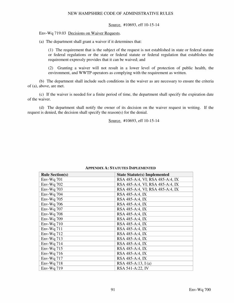
NEW HAMPSHIRE CODE OF ADMINISTRATIVE RULES
91 Env-Wq 700
Source. #10693, eff 10-15-14
Env-Wq 719.03 Decisions on Waiver Requests.
(a) The department shall grant a waiver if it determines that:
(1) The requirement that is the subject of the request is not established in state or federal statute or federal regulations or the state or federal statute or federal regulation that establishes the requirement expressly provides that it can be waived; and
(2) Granting a waiver will not result in a lower level of protection of public health, the environment, and WWTP operators as complying with the requirement as written.
(b) The department shall include such conditions in the waiver as are necessary to ensure the criteria of (a), above, are met.
(c) If the waiver is needed for a finite period of time, the department shall specify the expiration date of the waiver.
(d) The department shall notify the owner of its decision on the waiver request in writing. If the request is denied, the decision shall specify the reason(s) for the denial.
Source. #10693, eff 10-15-14
APPENDIX A: STATUTES IMPLEMENTED
Rule Section(s) State Statute(s) Implemented
Env-Wq 701 RSA 485-A:4, VI; RSA 485-A:4, IX Env-Wq 702 RSA 485-A:4, VI; RSA 485-A:4, IX Env-Wq 703 RSA 485-A:4, VI; RSA 485-A:4, IX Env-Wq 704 RSA 485-A:4, IX Env-Wq 705 RSA 485-A:4, IX Env-Wq 706 RSA 485-A:4, IX Env-Wq 707 RSA 485-A:4, IX Env-Wq 708 RSA 485-A:4, IX Env-Wq 709 RSA 485-A:4, IX Env-Wq 710 RSA 485-A:4, IX Env-Wq 711 RSA 485-A:4, IX Env-Wq 712 RSA 485-A:4, IX Env-Wq 713 RSA 485-A:4, IX Env-Wq 714 RSA 485-A:4, IX Env-Wq 715 RSA 485-A:4, IX Env-Wq 716 RSA 485-A:4, IX Env-Wq 717 RSA 485-A:4, IX Env-Wq 718 RSA 485-A:13, I (a) Env-Wq 719 RSA 541-A:22, IV
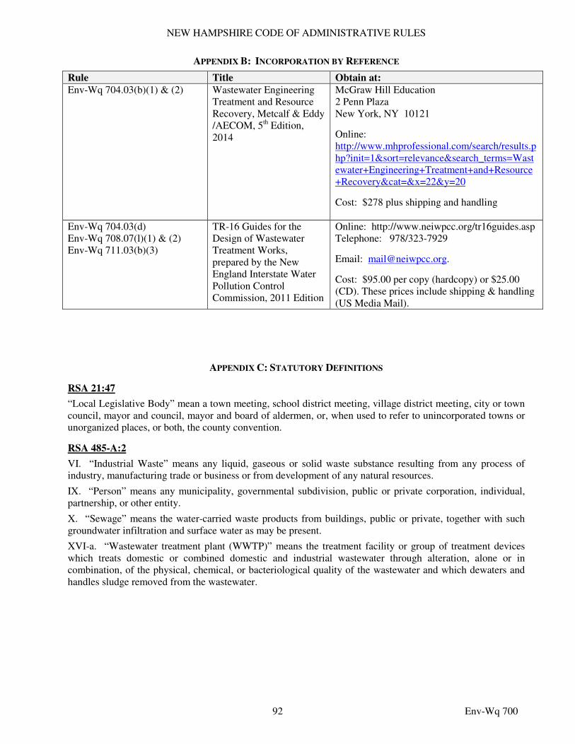
NEW HAMPSHIRE CODE OF ADMINISTRATIVE RULES
92 Env-Wq 700
APPENDIX B: INCORPORATION BY REFERENCE
Rule Title Obtain at:
Env-Wq 704.03(b)(1) & (2) Wastewater Engineering Treatment and Resource Recovery, Metcalf & Eddy /AECOM, 5th Edition, 2014
McGraw Hill Education
2 Penn Plaza
New York, NY 10121
Online: http://www.mhprofessional.com/search/results.php?init=1&sort=relevance&search_terms=Wastewater+Engineering+Treatment+and+Resource+Recovery&cat=&x=22&y=20
Cost: $278 plus shipping and handling
Env-Wq 704.03(d)
Env-Wq 708.07(l)(1) & (2)
Env-Wq 711.03(b)(3)
TR-16 Guides for the Design of Wastewater Treatment Works, prepared by the New England Interstate Water Pollution Control Commission, 2011 Edition
Online: http://www.neiwpcc.org/tr16guides.asp
Telephone: 978/323-7929
Email: [email protected].
Cost: $95.00 per copy (hardcopy) or $25.00 (CD). These prices include shipping & handling (US Media Mail).
APPENDIX C: STATUTORY DEFINITIONS
RSA 21:47
“Local Legislative Body” mean a town meeting, school district meeting, village district meeting, city or town council, mayor and council, mayor and board of aldermen, or, when used to refer to unincorporated towns or unorganized places, or both, the county convention.
RSA 485-A:2
VI. “Industrial Waste” means any liquid, gaseous or solid waste substance resulting from any process of industry, manufacturing trade or business or from development of any natural resources.
IX. “Person” means any municipality, governmental subdivision, public or private corporation, individual, partnership, or other entity.
X. “Sewage” means the water-carried waste products from buildings, public or private, together with such groundwater infiltration and surface water as may be present.
XVI-a. “Wastewater treatment plant (WWTP)” means the treatment facility or group of treatment devices which treats domestic or combined domestic and industrial wastewater through alteration, alone or in combination, of the physical, chemical, or bacteriological quality of the wastewater and which dewaters and handles sludge removed from the wastewater.
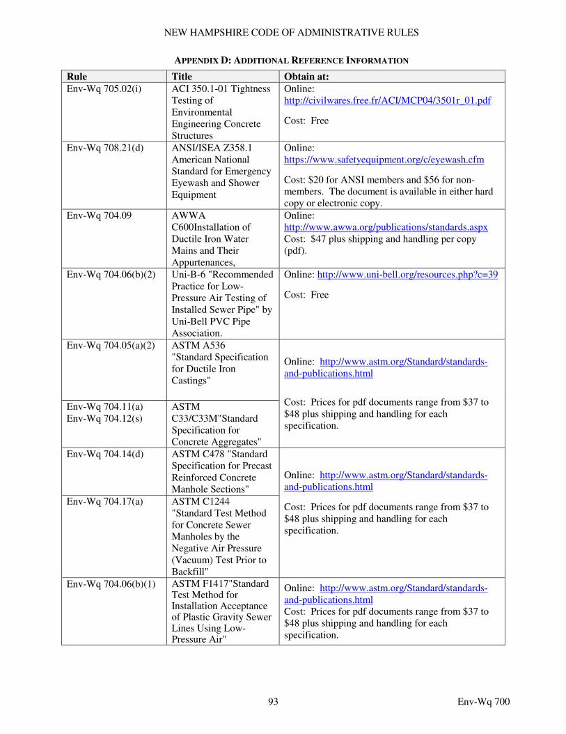
NEW HAMPSHIRE CODE OF ADMINISTRATIVE RULES
93 Env-Wq 700
APPENDIX D: ADDITIONAL REFERENCE INFORMATION
Rule Title Obtain at:
Env-Wq 705.02(i) ACI 350.1-01 Tightness Testing of Environmental Engineering Concrete Structures
Online: http://civilwares.free.fr/ACI/MCP04/3501r_01.pdf
Cost: Free
Env-Wq 708.21(d) ANSI/ISEA Z358.1 American National Standard for Emergency Eyewash and Shower Equipment
Online: https://www.safetyequipment.org/c/eyewash.cfm
Cost: $20 for ANSI members and $56 for non-members. The document is available in either hard copy or electronic copy.
Env-Wq 704.09 AWWA C600Installation of Ductile Iron Water Mains and Their Appurtenances,
Online: http://www.awwa.org/publications/standards.aspx
Cost: $47 plus shipping and handling per copy (pdf).
Env-Wq 704.06(b)(2) Uni-B-6 "Recommended Practice for Low-Pressure Air Testing of Installed Sewer Pipe" by Uni-Bell PVC Pipe Association.
Online: http://www.uni-bell.org/resources.php?c=39
Cost: Free
Env-Wq 704.05(a)(2) ASTM A536
"Standard Specification for Ductile Iron Castings"
Online: http://www.astm.org/Standard/standards-and-publications.html
Cost: Prices for pdf documents range from $37 to $48 plus shipping and handling for each specification.
Env-Wq 704.11(a)
Env-Wq 704.12(s) ASTM C33/C33M"Standard Specification for Concrete Aggregates"
Env-Wq 704.14(d) ASTM C478 "Standard Specification for Precast Reinforced Concrete Manhole Sections"
Online: http://www.astm.org/Standard/standards-and-publications.html
Cost: Prices for pdf documents range from $37 to $48 plus shipping and handling for each specification.
Env-Wq 704.17(a) ASTM C1244
"Standard Test Method for Concrete Sewer Manholes by the Negative Air Pressure (Vacuum) Test Prior to Backfill"
Env-Wq 704.06(b)(1) ASTM F1417"Standard Test Method for Installation Acceptance of Plastic Gravity Sewer Lines Using Low-Pressure Air"
Online: http://www.astm.org/Standard/standards-and-publications.html Cost: Prices for pdf documents range from $37 to $48 plus shipping and handling for each specification.
NEW HAMPSHIRE CODE OF ADMINISTRATIVE RULES
94 Env-Wq 700
APPENDIX E: OTHER STATUTORY REFERENCES
RSA 641:3
A person is guilty of a misdemeanor if:
I. He or she makes a written or electronic false statement which he or she does not believe to be true, on or pursuant to a form bearing a notification authorized by law to the effect that false statements made therein are punishable; or
II. With a purpose to deceive a public servant in the performance of his or her official function, he or she:
(a) Makes any written or electronic false statement which he or she does not believe to be true; or
(b) Knowingly creates a false impression in a written application for any pecuniary or other benefit by omitting information necessary to prevent statements therein from being misleading; or
(c) Submits or invites reliance on any writing which he or she knows to be lacking in authenticity; or
(d) Submits or invites reliance on any sample, specimen, map, boundary mark, or other object which he or she knows to be false.
III. No person shall be guilty under this section if he or she retracts the falsification before it becomes manifest that the falsification was or would be exposed.


