

EPA/ROD/R10-02/106 2002
EPA Superfund
Record of Decision:
KAISER ALUMINUM (MEAD WORKS) EPA ID: WAD000065508 OU 01 MEAD, WA 05/01/2002

Exhibit B
CLEANUP ACTION PLAN
Kaiser Aluminum National Priorities List Site Mead, Washington
Prepared by
Washington Department of Ecology
May 1, 2002
Table of Contents 1.0 Introduction
1.1 Purpose ................................................................................................................................1 1.2 Facility Description .............................................................................................................2 1.3 Applicability ........................................................................................................................3 1.4 Declaration ..........................................................................................................................5 1.5 Administrative Record ........................................................................................................5
2.0 Site Description And History
2.1 Site Location and Background Information ........................................................................5 2.2 Site History .........................................................................................................................9 2.3 Current Status ....................................................................................................................10 2.4 Future Use .........................................................................................................................10
3.0 Results of Environmental Studies
3.1 Site Characterization – Physical Characteristics and Geology .........................................10 3.2 Chemicals of Concern .......................................................................................................14
4.0 Media Cleanup Levels
4.1 Selection of Method for Establishing Cleanup Levels .....................................................20 4.2 Media Cleanup Levels ......................................................................................................21 4.3 Points of Compliance ........................................................................................................22
5.0 Summary of Alternative Cleanup Levels
5.1 Introduction – Summary of Cleanup Alternatives ............................................................22 5.2 Summary of Applicable Technologies ..............................................................................25 5.3 Development of Cleanup Alternatives ..............................................................................28
6.0 Proposed Cleanup Alternative
6.1 Site Cleanup Alternative ...................................................................................................34 6.2 Operation, Maintenance, and Monitoring Plans ...............................................................41 6.3 Financial Assurances .........................................................................................................43 6.4 Institutional Controls ........................................................................................................43 6.5 Schedule ............................................................................................................................43
i
Cleanup Action Plan
Kaiser Aluminum — Mead Works Kaiser Mead NPL Site
Mead, Washington
May 1, 2002
1.0 INTRODUCTION 1.1 PURPOSE This document is the Cleanup Action Plan (CAP) for the Kaiser Aluminum Mead Works - Nation Priorities List (NPL) Site. The CAP outlines the steps and procedures for conducting an environmental cleanup of the Kaiser Mead NPL Site ("the Site") and includes data and site specific information obtained for various assessment reports and work plans. The purpose of this Cleanup Action Plan is to:
• Summarize the interim remedial actions that have been completed at the site.
• Describe the proposed final cleanup action and monitoring plans including the rationale used to select both the plans.
• Provide an opportunity for the public to comment on the proposed final cleanup action.
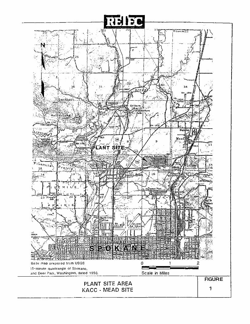
The cleanup was began as an agreed order interim action, with the construction of a double lined cover to complete source control activities at the site and will end with a consent decree to direct the cleanup of contaminated groundwater using a pump and treatment system, pipe repair and institutional controls. 1.2 FACILITY DESCRIPTION The Kaiser Mead NPL Site is located on the Kaiser Aluminum smelter complex within Section 16, Township 26 North, Range 43 east, approximately seven miles north of Spokane, Washington and one mile southwest of Mead, Washington (Figure 1). The facility is a prebake aluminum smelter that was constructed during WWII in 1942. The plant covers approximately 270 acres and the area immediately adjacent to the plant is zoned for industrial use. The nearest residential properties are located approximately 1500 feet to the northwest of the plant. The Kaiser Aluminum & Chemical Corporation has owned the plant site since 1946. The NPL Site consists of 25 to 30 acres located in the western portion of the plant
1
.oc---C
-J..---:.._. L-~ '
-·~t;....--!,,-'--'--f----r"'i:, . j ·-· .,
0
;l't,;.,.,,f'i,22 j
1 2 Base map prepared from USGS
15-minute quadrangle of Spokane. -- -and Deer Park, Washing1on, dated 1950.
PLANT SITE AREA KACC - MEAD SITE
Scale in Miles
-:_-;i. l
FIGURE
1

where a waste material known as potliner was traditionally disposed and a groundwater contamination plume exists that extends from the northwest corner of the plant for approximately two and one half miles to the Little Spokane River. The plant operates eight potlines, an anode plant with bake ovens, dry scrubbers for air emissions control, pot-reworking facilities, indoor storage facilities and miscellaneous other buildings used in support of the smelter. Potlining and other waste materials have been handled and are located on 25 to 30 acres located within the western portion of the plant (Figure 2). The spent potlining is covered with a recently constructed double lined cover (Ecology Order DE 01 TCPIS-2075). In this area the major features prior to the interim action cover project included:
• An asphalt covered pile of spent potlining (SPL) materials;
• A solid waste pile known as the "rubble pile" consisting of bricks, metal, wood, and some potlining;
• A butt tailings pile;
• A sludge bed containing wet scrubber sludges;
• An abandoned settling basin (Tharp Lake);
• An abandoned potliner storage area;
• A failed cell demolition building;
• A sewage treatment plant;
• Asphalt paved areas.
Cyanide and fluoride contaminated groundwater is found under the northwest portion of the Site. 1.3 APPLICABILTY This CAP is applicable only to the Kaiser Mead NPL Site. The cleanup standards and cleanup actions presented in this document have been developed as a result of a remediation process conducted with the Department of Ecology (Ecology)oversight. The cleanup leve ls and actions are Site specific and should not be considered as setting precedents for other similar sites. Ecology is the SEPA lead agency for this action. A threshold determination has been made to issue a Determination of Non-significance (DNS) for this cleanup project. The DNS will be publicly noticed concurrently with the CAP. A public hearing will be held concerning the action. Kaiser Aluminum is exempt from shoreline permitting and from a Hydraulic Project
3
I I
,·-- -====~---·I
POT LINING WASTE STORAGE BUILDINGS
16030
l._
ORA\11'1 BY
"" D-IK'O BY
"" SC'1.E
' '
c,. 12/Jl/92
"" 12/Jl/92
"'"'
' '- --·-
TEMPORARY POlUNING STORAGE AREA
(NOT USED)
~ ~
16F2 16F30 0
D = - ~
=o D
'C:::r=
1 ::J D
= D
n
ABANDONED HOLDING PO;iD
SEWAGE TREATMENT PLANT
SEffilNG BASIN (THARP LAKE) (ABAN~JNED)
LEGEND 16D3 INDUSTRIAL WELL LOG,'. TION
0 ANO NUMBER
@caj PROJECT AREAc
~ ASPHAI T COVERED AREA,; .. \ KA:SER PROPERTY BORDER
~~--=-1== -·-----·--·--·---~ - ·-- ~-::---- ·-'--·---,
.
SLUDGE BED
0 0
11 11 11 11 11
D
D I o ·o 0 D
= 11 11
D 0 0
I
. I I
I I
~
' "' WO
FACILITY SITE PLAN KACC - MEAD SITE
,,,-,., L<-.r- ~

approval from the Department of Wildlife. Kaiser Aluminum has independently applied for a local grading permit from Spokane County. The project is designed to be consistent with the Spokane County standard specifications and drainage ordinances. At this time no additional permits are required. In the event Ecology or Kaiser Aluminum determines that additional permits are necessary for the remedial action, Kaiser Aluminum will be notified and the substantive requirements of the permit will be determined and fulfilled. Potentially Liable Persons (PLP's) cleaning up sites independently, without Ecology oversight, may not cite numerical values of cleanup levels specified in this document as justification for cleanup levels in other unrelated sites. PLP's that are cleaning up sites under Ecology oversight must base cleanup levels and cleanup standards on site specific regulatory considerations and not on numerical values contained in this CAP. 1.4 DECLARATION The selected remedy will be protective of human health and the environment. Ecology gives preference to permanent solutions to the maximum extent where practicable. The selected remedy complies with cleanup standards for cyanide and fluoride, provides for adequate compliance monitoring and complies with current state and federal laws governing cleanup activities. For this remediation project recycle, treatment and disposal technologies for the removal of the potliner were examined but not used. These three different technologies were not selected because the recycle technology is unproven, and the cost differences between potliner recycle, treatment, or disposal alternatives were disproportionate to the incremental degree of protection provided when compared to containment remedies. Containment of the spent potliner by a double lined landfill cover, performance monitoring and institutional controls are the Ecology approved cleanup remedies for the potliner material found on the Site. The containment remedies were completed under an interim action Agreed Order DE 01 TCPIS-2075 in 2001 Groundwater and the Little Spokane River are affected by contaminants originating from the Site. Water treatment technologies using a groundwater pump and treat system were examined and were considered practical for this Site. Groundwater treatment, source control (capping) and institutional controls are the chosen groundwater remediation strategies for the Site. 1.5 ADMINISTRATIVE RECORD The documents used to make the cleanup decisions discussed in this cleanup action plan constitute the administrative record for the Kaiser Mead NPL Site. These documents are listed in Appendix A of this document. Additional documents located in Department of Ecology Industrial Section Files in Olympia, Washington are also considered a part of the administrative record for the Site. The administrative record and the plant environmental files can be viewed by calling the Industrial Section secretary at (360) 407-6916 to schedule an appointment.
5

An analysis of applicable state and federal laws for the NPL Site was completed in 1989 by CH2M Hill during the completion of the remedial investigation. This document is available for review at the Department of Ecology Industrial Section Files in Olympia, Washington.
2.0 SITE DESCRIPTION AND HISTORY 2.1 SITE LOCATION AND BACKGROUND INFORMATION The Kaiser Aluminum Mead Works was built in 1942 and originally operated by ALCOA. In, 1946, Kaiser Aluminum & Chemical Corporation leased and then purchased the facility and has operated it until the present day. The plant incorporated waste management and disposal practices consistent with the 1940 - 1950 era. A plan view of the Mead Works and potliner site is given in Figure 2. The plant is located within a glacial outwash valley about 2.5 miles from the Little Spokane River and has a surface elevation of about 2,000 feet. The land surface slopes gradually toward the Little Spokane River. The natural groundwater flow beneath the facility flows in a similar direction. Primary aluminum production involves the electrolytic reduction of aluminum oxide (Al203) to elemental aluminum in molten cryolite (Na3AlF6) called "bath". The process takes place in a reduction cell, or "pot", which consists of a rectangular reinforced steel shell generally lined with a carbon cathode surrounded by an insulating material (Figure 3). High temperatures are generated from electrical resistance heating, which keeps the aluminum and cryolite bath in a molten state. This molten material is the electrolyte. The carbon cathode contains steel collector bars for conducting electric current through the cell or pot. These collector bars extend through the side of the pot to the negative pole of the power supply. The positive pole of the power supply is connected to the anode. The anodes are made of carbon and are attached to the cell by a superstructure that suspends them using a copper rod into the molten cryolite bath. Reduction occurs when aluminum oxide is fed into the molten electrolyte and current is passed from the cathode to the anode though the bath. Electrolysis breaks down the aluminum oxide into aluminum metal and oxygen that combines with the carbon in the anode to form carbon dioxide and carbon monoxide. The carbon anode is consumed in the aluminum smelting process, but the cathode is not. The molten elemental aluminum sinks to the bottom of the pot and is removed periodically for casting. A typical pot may operate for two to five years before it needs to be removed for replacement. A pot fails when iron from its shell or collector bars is detected in the elemental aluminum, or when the insulation and carbon layer fractures and the shell leaks molten aluminum. When a cell fails the insulation and carbon block layers are removed and the steel shell is relined. The removed lining is called "spent potlining" and is contaminated with
6
cyanide and fluoride. The cyanide is created when atmospheric nitrogen combines and reacts with the carbon cathode blocks under the high temperatures of aluminum production. The fluoride originates from the cryolite in the bath material. Historically, there have been several wastes generated in addition to spent potliner during the manufacture of aluminum at the Mead Works. The primary wastes associated with production were:
• Spent potlining • Pot soaking liquor • Sludges from air pollution control equipment • Used anode waste called butt tailings • Fire brick and general solid waste
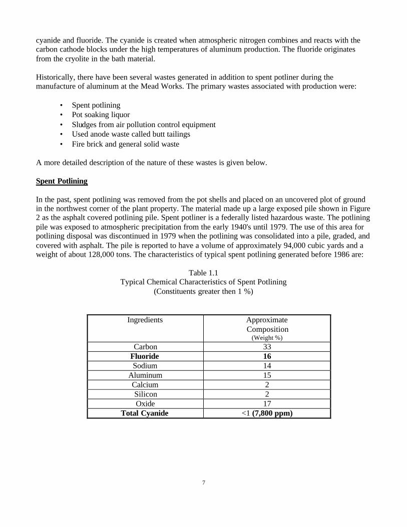
A more detailed description of the nature of these wastes is given below. Spent Potlining In the past, spent potlining was removed from the pot shells and placed on an uncovered plot of ground in the northwest corner of the plant property. The material made up a large exposed pile shown in Figure 2 as the asphalt covered potlining pile. Spent potliner is a federally listed hazardous waste. The potlining pile was exposed to atmospheric precipitation from the early 1940's until 1979. The use of this area for potlining disposal was discontinued in 1979 when the potlining was consolidated into a pile, graded, and covered with asphalt. The pile is reported to have a volume of approximately 94,000 cubic yards and a weight of about 128,000 tons. The characteristics of typical spent potlining generated before 1986 are:
Table 1.1 Typical Chemical Characteristics of Spent Potlining
(Constituents greater then 1 %)
7
Ingredients Approximate Composition
(Weight %) Carbon 33
Fluoride 16 Sodium 14
Aluminum 15 Calcium 2 Silicon 2 Oxide 17
Total Cyanide <1 (7,800 ppm)

Components of a Typical On-Line Pot
Figure 3
8
Physical Data
• Solid • Black to Gray • Characteristic ammonia odor when damp • pH approximately 11.0 • Specific gravity 2.5 • Solubility in water 3 to 4 percent
Pot Soaking Liquor Until late 1978, the failed pots were taken off line and transported to a cement slab located on the southeast side of the potlining pile in the vicinity of Area 2 and Area 3 (Figure 2). Here the pots were filled with water and allowed soak for several days. The water soaking thermally cracked and loosened the carbon and insulation material from the steel shells. The pot soaking water was removed and disposed of on the ground next to the slab and sometimes into the sludge drying beds located next to the digging area. The contaminated water soaked into the soils beneath the pot soaking area and the potliner pile. The pot soaking liquor contained high levels of cyanide and fluoride. Once the spent potlining was loosened from the pot, it was removed using jackhammers and placed in the potlining pile. The practice of soaking was discontinued in 1978 when cyanide and fluoride contamination was discovered in groundwater beneath the Mead Works. Wet-Air Scrubber Sludge Wet-air scrubbers were used prior to 1974 at the Mead Works. These scrubbers generated sludges with high fluoride content which were disposed of in a settling pond, known as the sludge bed in Figure 2, near the potliner pile. Wet scrubbing was conducted to remove various constituents, including fluoride, from the off-gas of the potlines prior to atmospheric release. Calcium carbonate or calcium oxide slurry was sprayed through the off-gas venturi scrubber to precipitate calcium fluoride that was then removed in a settling pond. The calcium fluoride formed sludge. The wet scrubbing system was replaced with a dry scrubber beginning in the mid 1970's. The dry scrubber recycles the fluoride in the off-gases by passing the gases through a stream of aluminum oxide ore which is then used in the potrooms for aluminum production. The wet scrubber sludge has been tested and does not designate as dangerous waste but contains low levels of calcium fluoride. Anode Butt Tailings A large pile of granular carbon material is located next to the potliner pile. This material is known as anode butt tailings. The pile was generated by screening the fines from a tumbling process that was used to clean anode butts after their removal from the anode rods during the
9

period of approximately 1960 to 1982. The pile is not dangerous waste and contains no cyanide. This material was used to level the potliner pile during the cover construction. Brick and Rubble Pile (“Rubble Pile”) The brick and rubble pile (rubble pile) is located immediately northwest of the spent potlining piles. The rubble pile received refractory brick from the plant bake ovens, general industrial waste, miscellaneous construction debris, and some potliner. The pile contains metal, brick, wood, concrete, anode butts, and some spent potliner. 2.2 Site History The Department of Ecology became aware of the cyanide and fluoride groundwater contamination found at the Mead Works in late 1978. Kaiser initiated a groundwater investigation that showed contamination was present in domestic wells northwest of the plant. The findings were reported to the Spokane County Health Department and a more extensive sampling program was started in the affected area northwest of the Mead Works. The suspected source of the cyanide and fluoride contamination was spent potlining wastes from aluminum production. Kaiser arranged for alternative potable water supplies to be provided to persons whose residential wells were contaminated with cyanide. Kaiser offered residents with contaminated wells options of a permanent hook up to public water, a deionizer for the existing well or a newly constructed well. One new well was drilled and 25 individuals were hooked up to the public water system. 2.3 Current Status The site is located on a currently inactive aluminum smelter. The potliner pile is surrounded on the east, west, and southern sides by the facilities operational areas. The north side of the site boundary is a BPA power line corridor that is located on Kaiser Aluminum Company property. The property is zoned as heavy industry. The closest neighborhoods are situated to the northwest of the plant approximately 1,500 feet. The land use in the area is mixed consisting of commercial, industrial and residential. The area has grown more urban residential rather than rural in the last 15 years. 2.4 Future Use The Kaiser Mead Site has been used for industrial purpose since World War II, and is currently zoned for heavy industry. Future use of the site is unknown at this time. The existing aluminum smelter owned by Kaiser is currently temporarily curtailed but is anticipated to restart. The property north of the site is owned by Kaiser and leased to a sod farm. Future development plans for this portion of the site are unknown.
10

3.0 RESULTS OF ENVIRONMENTAL STUDIES 3.1 Site Characterization - Physical Characteristics & Geology The Kaiser Aluminum Mead Works is located within a glacial outwash valley and has a surface elevation of approximately 2,000 feet. The land surface slopes gradually toward the Little Spokane River to the northwest of the plant to an elevation of less than 1,600 feet. The average annual precipitation as measured at the Spokane airport is 16.4 inches. About 70 percent of the rain falls between the first of October and the end of April. Summer temperatures at the airport range between 80 and 90 degrees F during the day and 45 to 60 degrees F during the night. Winter highs range between 25 and 45 degrees F with lows of 15 to 25 degrees F. Hydrogeologic System The Kaiser Mead Works lies over the Hillyard Trough portion of the Spokane-Rathdrum Aquifer. The plant lies above the sole source Spokane-Rathdrum Prairie aquifer. Groundwater flows beneath the plant from the east/southeast to the northwest where discharge to the Little Spokane River occurs through a series of springs. The Spokane-Rathdrum Prairie Aquifer is the major source of water to the Spokane area (Figure 4). The aquifer extends westward from the Washington State line to the east side of the City of Spokane and then turns northward toward Long Lake. The aquifer boundaries in the Hillyard Trough are composed of flow basalts or granitic intrusives except for the area from approximately one half mile south of Mead to the southeastern part of Section 4 where the boundary is composed of glaciolacustrine deposits. Glaciolacustrine deposits lie below the Peone Prairie found west of Mead, WA and the plant site. The aquifer materials consist of glaciofluvial sands and gravels with cobbles, boulders, and scattered clay and silt lenses, which were deposited in a pre-existing bedrock valley. The subsurface geology in the project area can be divided into three hydrogeologic zones: unsaturated zone, regional aquifer, and regional aquitard. The unsaturated (vadose) zone beneath the plant site is composed of a series of fine to coarse sand units interbedded with silty clay and clayey silt units. Some of the units are up to several feet in thickness and are thin and pinch out to the west. At least one clayey silt unit is continuous beneath the potliner pile and forms a small perched aquifer. The discontinuous sand and clay units thin to the west. Waters in the regional aquifer flow generally parallel to the trend of the filled-in river valley (Hillyard Trough). The water table lies at a depth of approximately 150 to 160 feet below the plant site. The aquifer thickness is estimated to be over 100 feet thick beneath the smelter. The aquifer also thins to the northeast. Flow velocities in the aquifer have been estimated to be as high as 40 feet per day down gradient from the plant. Beneath the plant, flow velocities are estimated to be 3 to 4 feet per day in Zone A. Recharge to the aquifer occurs primarily to the east of Spokane where runoff from precipitation and snow melts, falling on mountainous
11

12
LEGEND ~w::;:. 1 ' . . '
H 1 e WELL LOCATION ANO NUMBER .J__l_.).-l.. AQUIFER BOUNDARY \J23' -, -- _ ~-
~L.~.~C~1=~~~~.~.ft~·'.~~S~",;~~:~G~L~:r~C/A'.:~::~.~;ll.~. O~N-U:M-B~E-R~hl~-~-~-,OID--~-:~•~W;A;J~E'R:T~Ai8~L~EjC~O~NT~O~U~R~J -4~ti~f==::===-~-t--.l~:~
f:]{J O .5 2 -~(. -~9 m11 : f--~~~---.J,:~: (/--;'_c:' 'c:,__-:.. SCALE IN M1L£S . •::; ·- 26_
P"., ·;;·;::~;LJ
REGIONAL HYDROGEOLOGIC SETTING KACC - MEAD SITE
••
- p.
·-
FIGURE
4

areas, infiltrate into the aquifer. Analysis of precipitation data and soil conditions ind icates that little, if any, recharge occurs from local rain or snowfall. However, recharge from continuous plant pipe leaks and unlined lagoons have been shown to contribute to the aquifer. Aquifer discharge occurs into the Little Spokane River approximately 2.5 miles northwest of the plant. The discharge at the springs has been estimated by the U.S. Geological Survey to be 150 to 310 cfs and forms a significant portion of the river flow (Figure 4). The top portion of the regional aquifer (35 feet) is vertically stratified into relatively permeable zones separated by fine-grained sediments that form aquitards. These units at the Kaiser Site are known as Zone A, B and C (with increasing depths). Zone A is an unconfined aquifer while Zone B and Zone C are semi-confined aquifers. The majority of the cyanide and fluoride in groundwater is found in Zone A (Figure 5). Zone A ranges in thickness from 5 feet to 15 feet. It has a typical thickness of 10 to 15 feet. The zone is composed of silty sand and fine to coarse sand and thins to the west. Zone B is composed of clean, fine to coarse sand and ranges in thickness from 5 to 20 feet. It is separated from Zone A by a sandy silt/clay unit which ranges in thickness from 5 to l 0 feet. Zone C is composed of fine to medium sand that grade into sand and gravel at depth. The zone is approximately 70 to 80 feet thick beneath the Mead Works. It is separated from Zone B by a 1 to 7 foot clay unit. The regional aquifer is underlain by a regional aquitard composed of silt and clay interbedded with occasional lenses of sand and gravel. The top of the aquitard is 270 to 280 feet beneath the plant site and defines the bottom of the regional aquifer. 3.2 Chemicals of Concern Cyanide and fluoride are the only two chemicals of concern found at the Kaiser Mead NPL Site. Cleanup actions discussed in this cleanup action plan address only cyanide and fluoride contamination. Cyanide and fluoride are found in spent potliner waste, soils, and groundwater at the Site. Spent Potliner Spent potliner is mainly composed of carbon (33%), fluoride (16%), sodium (14%), aluminum (15%), and oxide (17%). In 1983 spent potliner from each smelter in the state of Washington was analyzed by the Department of Ecology to determine dangerous waste designation. Kaiser Mead Works spent potliner was analyzed by taking three pots with more than 400 days operation and crushing them to 3/8 inch size fraction. The resulting material was mixed and halved by a standard method until three 100-pound samples were available to test. These samples were then analyzed for total and soluble fluoride and free cyanide, total cyanide and soluble cyanide. The results from the five smelters in the state were highly variable. The Kaiser Mead data is shown below.
13

14
.... w w .....
1900
1800
?:; 1700 z 0 i= <( > w ...I w
1600
1500
DRAWN BY
DATE
CHK'D BY
DATE
SCALE CAD FILE:
-.93 ...L
365>
LEGEND
WATER TABLE
SCREENED SECTION AND CYAN1DE A"JALYSIS 1N ppb .
SPRING A,'.10 CYANIDE ANALYSIS IN ppb.
6J1
(STEINER-Tll:..:T.::.O.:..;.N,,__ __
~ WATER LEVEL
BG3 WELL NUMBER (POPE) AND OWNER
~ IMPERMEABLE ZONES
a:::
~ ---iE 6H1 - - ----
I KAISER TEST HOLES!
TH-6
SAND AND GRAVEL WlTH OCCASIONAL INTERBEDOED SILT ANO CLAY.
2000
1900
1BOO :::;V)
~ l'w t:
1700 ~ z 0 i=
1600
:; w ...J w
/;t:·:Jf!.:if}::fi.'fff::f[::ff!:ii:::,:i:}~:?:.->·;;/;;:.:... .. NOTE: THE LEVELS OF CYANIDE SHOWN GIVE THE APPROXIMATE RANGE OF CONCENTRATION AT THE PARTICULAR SAMPLING POINT PRIOR TO THE ABANDONMENT OF THARP LAKE
E.r. ·1/2V93
G.H.
1/21/93
NOTED
o 1000 2000 -4000 IN 1981. THE CONCENTRATIONS F'OR WELL BG3 (POPE) WERE DETERMINED f'ROM SAMPLES TAKEN DURING REPLACEMENT WELL DRILLING OPERA TlONS. 1500
APPROXU,l,t.T£ SCALt IN FEH
OOWNGRADIENT CYANIDE FLOW PATH PROFILE
KACC - MEAD SI TE l~ilHII
REMEDIATiON TECHNOLOGIES INC
l 012/93A014 FIGURE 5

Cyanide and Fluoride Analysis Kaiser Mead Works – Spent Potliner
1983
Total Cyanide 7,800 mg/kg (average) Soluble Cyanide 4,900 mg/kg (average)
Free Cyanide 3,800 mg/kg (average) Total Fluoride 80,600 mg/kg (average)
It has been determined that spent potliner and the pot soaking liquor are the primary sources of the cyanide and fluoride in the soil at the plant and the groundwater plume on and off site. Leachate and Groundwater Cyanide and fluoride are the predominant constituents in leachate from spent potliner waste. Total cyanide concentrations in leachate have been detected on the order of 700 to 1,000 mg/L while fluoride has been detected at concentrations of over 2,700 mg/L. Leachate characteristics were determined on spent potliner using the EP TOX test in 1978. The highest concentrations of total cyanide and fluoride in groundwater have been detected in a well screened in Zone A (TH-8) which is immediately downgradient of the spent potliner handling area shown in Figures 7 and 8. Total cyanide concentrations over of 250 mg/L and fluoride concentrations of over 200 mg/L have historically been detected in samples collected from this well. Soils and Vadose Zone Soil samples collected during the drilling of monitoring wells and within the potliner area have been analyzed for cyanide and fluoride. The highest soil cyanide and fluoride concentrations were measured in soil samples obtained within the potlining handling area to the east of the spent potliner pile. Soil cyanide levels range from 100 mg/kg to 10 mg/kg in samples collected above a depth of 50 feet. Concentrations in soils away from the covered pile and the potlining handling area decrease to less than 10 mg/kg. Cyanide concentrations in soil below a depth of 50 feet continue to decrease and are generally less than 100 mg/kg, with the highest levels being located in the potlining handling area. The highest soil levels are found on the silt and clay aquitards. Soil cyanide concentrations beneath the potlining material generally decline with depth. Soil beneath the spent potlining handling area represents the primary source of cyanide contamination of the underlying aquifer because the soils are within the migration pathway of plant induced recharge water sources. These water sources include infiltration from a now closed settling basin, pipe leaks, and infiltration of ponded runoff or snowmelt.
15

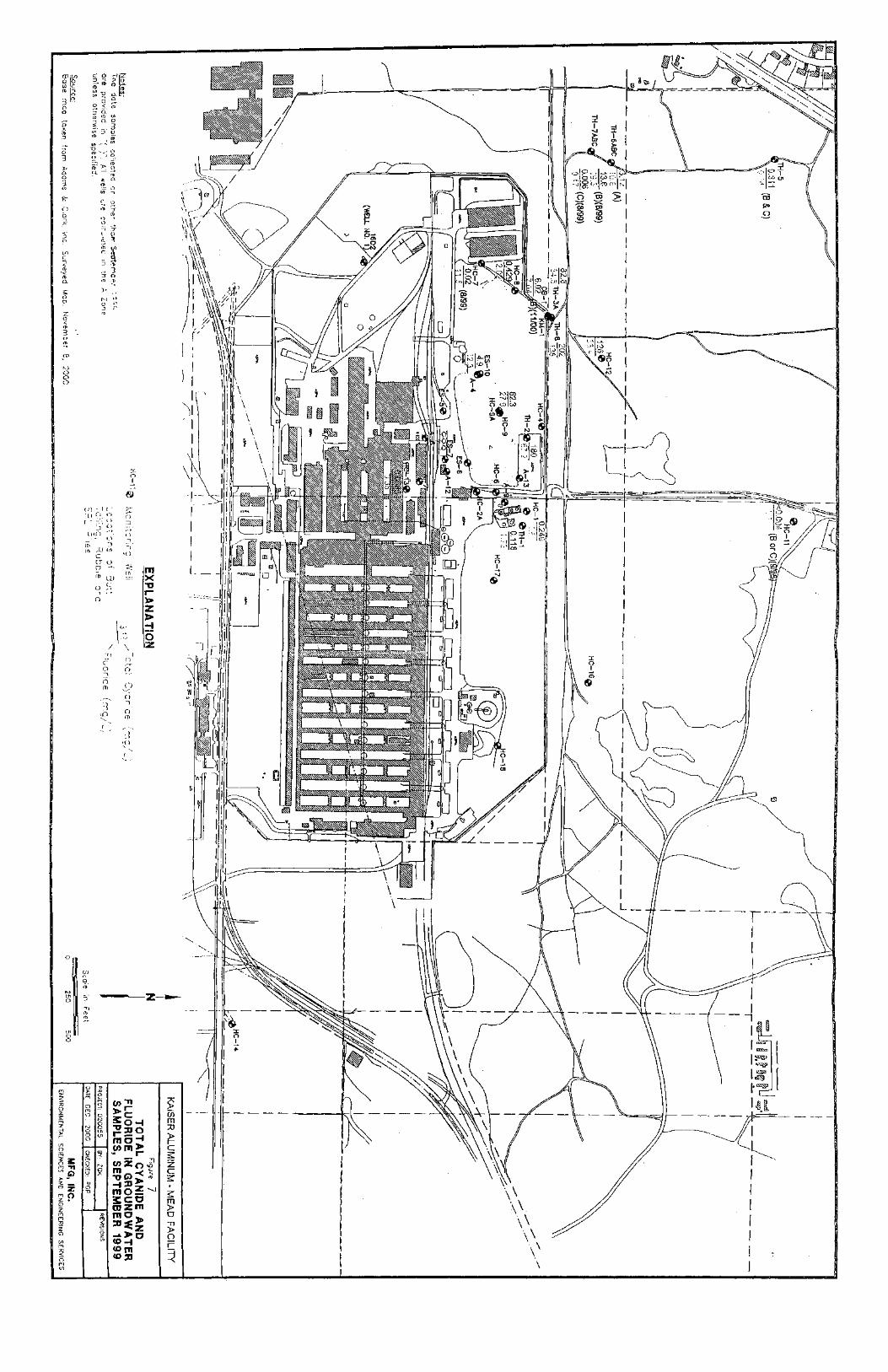
Groundwater Total cyanide and fluoride are measured as part of the Kaiser Mead Works groundwater monitoring program. The monitoring network measures the fluoride and cyanide contamination found in the 12,000 foot by 1,000-foot groundwater plume (Figure 6). The monitoring program began with over 80 wells in the monitoring network during the early 1980's. After the contamination plume was characterized and a public water system was constructed for the residents living above the contamination, the monitoring system was reduced to approximately 40 monitoring wells. Many of the original water wells that were used in monitoring network have been abandoned in the last twenty years as the public water system expanded northward from Spokane. In 1992, twenty-eight off site monitoring wells and twenty-two on site monitoring wells were analyzed during the data collection effort for the cleanup feasibility study. That number of off site wells has since decreased to approximately five or six wells. The county does not permit water wells from being drilled along the path of the plume. All of the recent growth in the area is served by the large water distric t. Three wells measured in the 1992 sampling event can be used to accurately describe the contaminated plume (Figures 6 & 7). The water quality data from these three locations in the network are representative of water quality throughout the plume of contamination. The locations have been selected because they are representative of the water quality at the property line near the contamination source (Well TH-8), immediately downgradient of the potliner area cyanide and fluoride source (Well TH-6), and at the discharge point to the Little Spokane River system (Spring W-195)(Figures land 8). Well TH-8 is located immediately downgradient of the waste handling area within the plume head and is the well where the highest cyanide and fluoride concentrations have been detected in the past. Total cyanide concentrations of over 250 mg/l (250,000 ug/L) and fluoride concentrations of over 200 mg/1 have historically been detected in samples collected from this well. Wells TH-6A, TH-6B, and TH6-C are located in the approximate horizontal center of the plume and are screened across Zone A, B, and C, respectively, with Zone A being the highest zone in the hydrologic unit. The nested wells are located approximately 1,600 feet northwest of the potliner pile site. The concentrations of cyanide and fluoride in groundwater from these three nested wells show decreasing values from 1983 through 1993. Values started increasing in the mid 1990's which caused a relative northward horizontal movement of the plume head. Typical total cyanide values in Zone A well TH-6A in the early 1980's were 25mg/L to 28 mg/L. Total cyanide in Zone A decreased to a low of 0.7 mg/L in 1994. Since the early 1990's, total cyanide has reversed the trend and increased to 4 mg/L. Free cyanide is at 0.36 mg/L. Fluoride values in Zone A well TH-6A generally do not follow the trend of total cyanide. The fluoride values stayed in the mid 20's mg/L range throughout the 1980's. In the early 1990's fluoride values in Zone A began to decrease and then seasonally fluctuate between 7 mg/L and a high of 18 mg/L in the mid-1990's.
16

\ Spr!nQ o Well A Tnl Holt
R. 4! E.
® Settthd Wnll or SprlnQ o u ,$ hllLl Showing Cyanidt >IOOppb ==.l
• Weier level E11v11t1on In Feet useo _r- water Taole €.!evation 1725 ln Conatruc1ion or Wottr Tabl• Mop. Con1our in fij~t
-U70. ···-
Source: Hort-Cro11s1r ond Associotn, 19BB.
l KAISER ALUMINUM· MEAD FACILITY
Figure 6 SITE MAP WITH
CONTAMINANT PLUME
MFG, INC, EN~RONMEtffAl SCtENctS AND (NCIN[EAING SER~CES

Monitoring well TH-6B in Zone B follows a decreasing trend with values of total cyanide reaching 100 mg/L in the early 1980's. In 1993 values of total cyanide had been reduced to 2-3 mg/L range. The well also began an upward trend in 1993 and since 1993 the values of total cyanide have increased to 30 mg/L. Free cyanide is at 1.29 mg/L. Fluoride monitoring in Zone B closely follows the cyanide trends. Fluoride values ranged as high as 80 mg/L in 1984. Concentrations of fluoride deceased to less than 1 mg/L throughout the 1980's and early 1990's. In 1996 Zone B fluoride values slowly started to increase and now are in the range of 30 mg/L. In Zone C total cyanide levels in 1983 were 0.1 mg/L. The total cyanide levels began to decrease in 1985 and 1986 to 0.005 mg/L. The total cyanide levels have remained at that level throughout the 1990's. Fluoride levels show similar trends. In 1984, fluoride ranged between 0.4 mg/L to 0.5 mg/L. The fluoride level had decreased to 0.1 mg/L by 1988. The fluoride levels have stayed in that range since the late 1980's. In 2000 fluoride was 0.19 mg/L, total cyanide was less than 0.004 mg/L, and free cyanide was not found above the 0.005 mg/L detection limit in well TH-6C. Spring location W-195 has historically had the highest cyanide concentrations where the contaminated aquifer discharges into the, Little Spokane River. The spring is located on a small hillside approximately 500 feet from the river. Typical total cyanide concentrations found in the spring during the early 1980's averaged 1.550 mg/L. In 1986 the total cyanide concentrations began to decrease to a low of 0.653 mg/L in 1995. After 1995 total cyanide concentrations began to increase again to a recent high of 1.460 mg/L in May of 1999. Recent samples (5/15/00) show total cyanide at 1.080 mg/L and free cyanide at 0.078 mg/L. Fluoride concentrations in this spring show very little variation. Fluoride concentrations range between 0.7 mg/L to .095 mg/L. Fluoride does not show the large historic changes that are present in the cyanide geochemistry of the aquifer over time. The concentrations of total cyanide and fluoride in monitoring wells on the plant site and from other wells in the vicinity of the cyanide plume have decreased in the past due to implementation of remedial measures that have reduced the migration of contaminants to the groundwater from the spent potlining and contaminated soils. This pattern has been reversed twice in the last twenty years when significant infiltration of water occurred because of significant pipe leaks at the Kaiser Mead Works. In general, the contamination in the upper portion of the aquifer has declined in the last twenty years but this decline is very dependent on control of these man-made infiltration events. Free cyanide concentrations in groundwater constitute a small fraction of total cyanide concentrations found in the plume at the site. Free cyanide is generally no more than 5 to 10 % of the sample. This relationship can be seen in the recent cyanide analysis at spring W-195. Total cyanide in the contaminant plume is comprised mostly of iron cyanide complexes. Hydrogeologic analyses of possible contaminant migration mechanisms to the water table indicate that natural precipitation alone is not sufficient to cause the measured concentrations of cyanide and fluoride that are found in the Spokane Aquifer. Data collected during the site evaluations and monitoring indicate that the infiltration of water into the vadose soil zone that
18
' " " z
' " 3 .
" "
" 0 0 0
0
'" o, 0
,-. ~ .. ' ' " .
" :, ·.;.
~ ~
'~ " ' . ) a" .. -~
•· "'" " " " ,. "
" n
' " <ll I [ :°::
·1, ,-, n o r --. " ~
_1 " UH> .-, •> - (_\ --,
n, :, , LO 21 rn •<l
" 0 " -,. :,, ITI ''' LU rn X
" ' '
~ ;-, ;!! 0 "'
h ' \ " (" (l
0 ()
.I '"
z .. :! 0 z
-~-z--
I
I : I
ll . I
I
=,_1. __ \~~~~--,1rr--~·t..:'·-'t
'9 I, I ~ I • I I i
- - - - ---j,;'
I I I ; I
1r--,c~ I ~li·:\ti:i;:~1--~L----1:\0;~!!._1 om ~I m I i I .; - - I
/
I I I I I I
-------,----1
I I~/::----
~I --~
iM [F~i i= I I·:_, c_
l~l _____ li_,: ---------------- I
------ -~ I .
I I I I I I I
contains cyanide and fluoride is required to form the current contaminated plume. Thus an additional water source is required from pot soaking, pipe leaks or significant ponding of storm water or snow melt to cause contaminant migration to the aquifer through the thick unsaturated zone. Since most of the spent potliner is located above where infiltration could reasonably occur, the primary source of contamination was first the potliner pile and pot soaking operation but now is considered to be the soil column which lies below the spent potlining pile and the past pot soaking operation since the pot soaking practice has been stopped and the potliner pile has been covered with an asphalt cap for approximately twenty years. Surface Water In 1980 a detailed biological assessment of the Little Spokane River was completed. The study by Hartung and Meier (1980) demonstrated that there have been no adverse impacts to the Little Spokane River as a result of the cyanide and fluoride plume. In 1995 Drs. Hartung and Meier again conducted another ecological survey of the Little Spokane River and found no adverse affects attributable to the plume entering the river. The 1995 study completed an in stream/spring toxicity study with caged fingerling rainbow trout and a detailed study of amphipods and associated macro- invertebrates which are sensitive to free cyanide. The 1995 work supports the findings of the 1980 study, that the minor variations in species and abundance of aquatic life was due to differences in stream flow, the character of the river bottom, water depth, and the presence or absence of aquatic plants. No effects on fish or macro- invertebrates were found attributable to cyanides in the Little Spokane River. The 1995 study extended the findings of the 1980 survey to include fish populations, their physical location, their food supply, and sensitive amphipod populations. In the aquifer discharge area at the Little Spokane River, the highest cyanide and fluoride concentrations have been detected in a spring that flows into the river (Spring W-195). Total cyanide has been detected at a maximum concentration of 1.6 mg/L in 1983 and decreased to less than 0.9 mg/L in the mid 1990's. Since 1997, total cyanide at Spokane River springs has increased to 1.4 mg/L. This is believed to have been caused by a leak in the buried NPDES outfall line that runs parallel to the potliner handling area. The leak was discovered in the pipe leak repair program in 2001. Fluoride has been consistently below 1 mg/L in the springs. Total and free cyanide and fluoride concentrations have been measured at several locations in the Little Spokane River. This sampling program was begun in the early 1980's and shows cyanide and fluoride effects of the groundwater plume entering the Little Spokane River. Total cyanide in the Little Spokane River has not exceeded 0.183 mg/L. Fluoride measurements are slightly above up stream levels of 0.10 mg/L and range from background to 0.26 mg/L. Cyanide trends in the Little Spokane River generally follow trends in the contaminated springs that feed the river. The level of cyanide in the river rapidly falls to background levels as one samples downstream.
20
4.0 MEDIA CLEANUP LEVELS
4.1 Selection of Method for Establishing Cleanup Levels The Model Toxics Control Act Cleanup (MTCA) Regulation provides three methods for determining cleanup standards for a contaminated site. The standards provide a uniform, statewide approach to cleanup that can be applied on a site-by-site basis. The two primary components of the standards, cleanup levels and points of compliance, must be established for each site. Cleanup levels determine at what level a particular hazardous substance does not threaten human health or the environment. Points of compliance designate the location on the site where the cleanup levels must be met. The three standard methods are known as Method A, Method B, and Method C. Method A applies to relatively straightforward sites that involve only a few hazardous substances. The method defines cleanup levels for 25 to 30 of the most common hazardous substances. The method also requires that the cleanups meet promulgated federal and state regulations such as the maximum contaminant levels established by the clean water act. Method B is a standard method that can be used at all sites. The cleanup levels are set using a site risk assessment that focuses on site characteristics or concentrations of individual hazardous substances established under applicable state and federal laws. In addition to accounting for human health impacts, Method B cleanup levels must account for any potential terrestrial or aquatic ecological impacts. Method C is similar to Method B. The main difference in the two methods is that the lifetime cancer risk is set at a lower number. The method can be used only when Method A or Method B is technically impossible, the site is defined as an industrial site, or attainment of Method A or Method B cleanup levels has the potential for creating a significantly greater overall threat to human health and the environment. As under Method B, potential terrestrial and aquatic ecological impacts must be accounted for in addition to human health impacts when establishing Method C cleanup levels. Unlike Method B, though, only the impacts on wildlife must be considered when conducting a terrestrial ecological evaluation. In addition, Method C also requires that the person undertaking the action comply with all applicable state and federal laws. 4.2 Media Cleanup Standards At the Kaiser Mead NPL Site two pathways exist for cyanide and fluoride to enter the environment. These pathways are through direct contact with contaminated soil and consumption of groundwater or surface water. MTCA requires that cleanup levels be based on reasonable maximum exposure which is the highest exposure that can be reasonably expected to occur for a human or other living organism at a site under current and potential future use. For the Kaiser Mead NPL Site the following cleanup standards are applicable for the proposed cleanup. Method A was intended to be used on relatively simple sites that require routine cleanup measures. Due to the presence of contaminants in the groundwater and the lack of Method A levels for cyanide and fluoride, Method A is not considered appropriate for this site.
21

Method B is the universal method for determining cleanup levels for all sites. Cyanide and fluoride are noncarcinogenic substances. For noncarcinogenic substances Method B cleanup levels are set at concentrations which are anticipated to result in no acute or chronic toxic effects on human health or no significant adverse effects on the propagation of aquatic and terrestrial organisms. Method B standards for cyanide and fluoride in groundwater, surface water and soil will be used at the Kaiser Mead NPL Site. The Method B groundwater standard for human health is the drinking water maximum contaminant level (MCL). The MCL for cyanide and fluoride will be used in groundwater WAC 173-340-720(4)(b). The Method B standard for surface water shall be the chronic water quality criteria for cyanide WAC 173-340-730(3)(b). There is currently no chronic water quality criteria for fluoride. Instead of the chronic water quality criteria for fluoride, the Method B groundwater standard of fluoride will be used at the groundwater/surface water interface in the springs feeding the Little Spokane River. The Method B standards for soil will be a standard that is protective of groundwater rather than the direct contact unrestricted land use value. The soil concentrations shall be those that will not cause contamination of ground water at levels which exceed the Method B groundwater cleanup standards. The soil concentration that will not cause an exceedance of the groundwater standard has been determined using a three-phase partitioning model for cyanide and fluoride (WAC 173-340-747). The target groundwater values used in the calculations were 200 ug/1 cyanide and 960 ug/l fluoride. The soil cleanup standards that were developed for cyanide and fluoride using the three phase model are significantly below the unrestricted MTCA Method B soil standards for cyanide and fluoride (1,600 mg/kg cyanide; 4,800 mg/kg fluoride). The cleanup standards for cyanide and fluoride at the Kaiser Mead NPL Site are given below.
MTCA Groundwater Cleanup Standards
Parameter Cleanup Standard Protection Basis Fluoride 4 mg/1 MCL
Cyanide (Free) 200 ug/1 MCL
MTCA Surface Water Standard
Parameter Cleanup Standard Protection Basis Fluoride 960 ug/l MTCA B
Cyanide (Free) 5.2 ug/1 Chronic Water Quality Criteria
22

MTCA Soil Cleanup Standards
Parameter Cleanup Standard Protection Basis Fluoride 2,884 mg/kg MTCA B
WAC 173-340-747 Cyanide (Free) 1 mg/kg MTCA B
WAC 173-340B-747 4.3 Points of Compliance There will be two points of conditional compliance for groundwater contamination at the Kaiser Mead NPL Site. One point of compliance will be based on human health and is located at the plant property boundary. The boundary is the northern edge of the plant, just south of monitoring well HC – 12 and directly north of the covered potliner pile. The cleanup standard for this point of compliance is derived under MTCA Method B derived from the drinking water standards (MCL) for cyanide and fluoride. The second point of conditional compliance for ground water at the site is a series of springs which are located at and around 13607 North Minihidoka Trail represented by Spring W-195. This is the point where groundwater becomes surface water at the site. This point of compliance is based on the chronic water quality criteria for cyanide and the MTCA B groundwater standard for fluoride. The soil cleanup point of compliance is the surface of the site and is based on a three phase partitioning model that determines soil concentrations that will not cause an exceedance of the groundwater standards. The soil standard is set to prevent the leaching of cyanide and fluoride into the groundwater from contaminated soils and spent potliners. Kaiser aluminum is using an engineered cap to both prevent human direct contact of cyanide and fluoride contaminated soil and spent potliners; and to prevent surface water from entering the site and remobilizing cyanide and fluoride found in contaminated soil. It is not expected that Kaiser Aluminum & Chemical will meet the soil cleanup standard at the Site because the selected remedy for soils is containment.
5.0 SUMMARY OF ALTERNATIVE CLEANUP ACTIONS 5.1 Introduction - Summary of Cleanup Alternatives This section of the cleanup action plan summarizes the cleanup actions that Kaiser Aluminum considered in the Feasibility Study for the Site. The Feasibility Study outlined a broad range of cleanup technologies that were applicable to spent potliner material, contaminated soil, and contaminated groundwater. The Feasibility Study separately evaluated source control and groundwater plume cleanup technologies. Approximately twenty-two source related cleanup technologies were evaluated in the Feasibility Study. The six major source control cleanup technologies that were chosen and then further examined are no-
23
Figure 8 SOURCE-RELATED CLEANUP TECHNOLOGIES EVALUATED IN
THIS FEASIBILITY STUDY
No-Additional Action Institutional Controls Containment
Capping Grouting Sheet Piles Slurry Walls Grout Curtain Reroute, Replace, or Repair Leaking Pipes Leak Monitoring
Removal Treatment
Recycle/Reuse Thermal Treatment In-Situ Vitrification Chemical Solidification/Stabilization (S/S) Washing Catalytic Oxidation Alkaline Hydrolysis UV/Chemical Oxidation Ex-Situ Bioremediation In-Situ Bioremediation
Disposal
On-Site Off-Site
Figure 8
Figure 9
SUMMARY OF INITIA.L SCREENING OF SOURCE-RELATED CLEANUP TECHNOLOGIES EVALUATED IN THIS
FEASIBILITY STUDY No-Additional Action YES Institutional Controls YES(1) Containment
Capping YES Grouting NO Ineffectiveness/Non-implementability Sheet Piles NO Excessive Depth to Subsoil Slurry Walls NO Excessive Depth to Groundwater Grout Curtain NO Excessive Depth to Groundwater Reroute, Replace, or YES Repair Leaking Pipes Leak Monitoring YES
Removal NO/Soil Excessive Volumes YES/SPL Treatment
Recycle/Reuse NO No Capacity or Demand Thermal Treatment NO Limited Experience/Capacity In-Situ Vitrification NO Limited Experience/Patented Chemical S/S NO Requires Excavation/Unproven CN Washing NO Unproven CN Catalytic Oxidation NO Experimental Stages Only Alkaline Hydrolysis NO Limited Treatment Capacity UV/Chemical Oxidation NO Not Applicable for Solid Matrix Ex-Situ Bioremediation NO Requires Excavation In-Situ Bioremediation NO Unproven CN
Disposal
On-Site NO Permitting/LDRS Off-Site YES
(l) currently implemented.
TECHNOLOGY RETAINED REASON FOR EXCLUSION

additional action, institutional controls, containment, removal, treatment, and disposal. Sub-sets of these technologies which were evaluated range from no additional action, capping and sheet piling to chemical treatment and reuse. The technologies evaluated and the initial screening criteria are shown in Figures 8 and 9. Results from the initial screening identified several cleanup technologies that may be effective in reducing source concentration to below cleanup levels. Those technologies that were retained and studied further are no-additional action – retained for comparison purposes, institutional controls – already in place at the Site, additional capping, infiltration control, and removal and off site disposal of spent potliner. The six major plume cleanup technologies evaluated in the feasibility study were no-additional action, institutional controls, containment, groundwater pump and treat, and disposal. Results from the initial screening effort identified three technologies that may be effective in reducing groundwater concentrations below the cleanup levels. Those three technologies are: no-additional action – retained for comparison purposes, institutional controls - already in place at the Site, and groundwater pump and treat with reinjection into the aquifer (Figures 10 & 11). 5.2 Summary of Applicable Technologies Eight representative technologies were retained for the remediation of contaminated material at the Kaiser Mead plant. These technologies were selected base on their effectiveness in reducing cyanide or potential cyanide migration and on their ability to be implemented. Some of the technologies are applicable only to the contamination source spent potliner and contaminated soil while others are applicable to groundwater. The technologies are as follows:
• No-Additional Action – (Spent potliner, soil, groundwater). This technology is retained in order to provide a baseline for comparison with other technologies.
• Containment – (Spent potliner, soil, groundwater). Capping also provides for source isolation
from human exposure, for proper site drainage, and for proper dust controls. Capping also provides a long term barrier to contaminant migration via precipitation and infiltration routes.
Extraction of contaminated groundwater occurs as part of hydraulic containment via a series of recovery and injection wells. This option will be capable of limiting plume migration within the current plume boundary. The concentration of cyanide in the plume will diminish with time due to extraction of the contaminants.
• Reroute, Replace, Repair Pipes\Leak Monitoring (soil). These measures provide for control
of contaminant migration from the vadose zone subsoil to the groundwater. These measures are combined with containment technologies to improve the reliability of the containment system. Excavation of spent potliner material for treatment and disposal was evaluated.
• Off-Site Disposal (Spent potliner). This option is applicable only for removal of spent
potlining.
26
Figure 10
PLUME-RELATED CLEANUP TECHNOLOGIES EVALUATED IN THIS FEASIBILITY STUDY
No-Additional Action Institutional Controls Containment
Physical Containment Hydraulic Containment
Groundwater Treatment Ex-Situ Treatment Methods
Biological Treatment Methods Physical Treatment Methods Chemical Treatment Methods
In-Situ Treatment Methods Pump-and-Treat
Treatment with On-Site Wastewater Treatment System Treatment in a POTW On-Site Ground Water Treatment
Disposal
Discharge to Settling Basin Use for In-Situ Soil Flushing Reinjection into Aquifer
Figure 11
SUMMARY OF INITIAL SCREENING OF PLUME-RELATED CLEANUP TECHNOLOGIES EVALUATED IN THIS STUDY
No-Additional Action YES Institutional Controls YES (1) Containment
Physical Containment NO Excessive Depth to Groundwater Hydraulic Containment NO Pump -and-Treat is a more Aggressive Option
Groundwater Treatment
Ex-Situ Methods Thermal Methods NO Inappropriate for Dilute Aqueous Wastes Biological Methods NO Ineffective for Complexed CN Physical Methods NO Precipitation Methods Work But Produce CN-Sludge Chemical Methods YES
In-Situ Methods NO Unproved for CN Pump -and-Treat
Treatment in Existing Wastewater Treatment System NO Hydraulically Overloaded Treatment in a POTW NO Not Suitable for Cyanide-Contaminated Water On-Site GW Treatment YES
Disposal
Discharge to Settling Basin NO May Not Meet Discharge Criteria Use for In -Situ Soil Flushing NO Unproven Reinjection into Aquifer YES
(1) currently implemented.
28
TECHNOLOGY RETAINED REASON FOR EXCLUSION
~ : ~·· AFFECTED RETAINED CLEANUP COMBINED SELECTION CRITERIA MEDIUM ACTIONS/ TECHNOLOGIES
Technology Permanent Restoration TECHNOLOGIES SPL, SOIL, OW (Alt•rnatlv. No.I Solutlon Time Frame
11. No Addldonal Action I I I I I '" I . I Vory !on11 for aw 1,4,8 111 No Additional Actlo11 No
I I I I I >30 .,.,
I 2, C•pplngi I I ,. I Oft-81te DlopauL I I Capping and LHchtno I I I I 2,10 yr for QW
I 2,6,8 '" ContNI for I I SPL end 8011
I I IPL and Son 1 • 2 yr SPL and 8011
I· NP Addttlonal Action I Soll I I ott .. lhl dlapout 8PL and I I YH IPL I I Vary Iona !or aw
I 3,4,1 131 no additional 1<1!1011 for No 8ol1 I I I 101 and OW I ' NGGW I I 1,2yrSPL
6. Luchlng Control
C.pplng, !.aching oontR>f I I YnBPL I I I 2,6.7 '" Yu ao• 2-10yrOW
18, No Addhfonal Aetlon I and pump and tNd I I v .. aw I I 1-2yrBPLand8 II Ornundwataf \
I 7. Pump-and•TIWat I I
0tt .. 1t, dlopoaal for SPL I I ,n Bl'L I I 2-10,,aw
I No 8oH 3,4,7 '" and pump and trn1 I I I 1-2yr&Pl v .. aw I
SUMMARY OF CLEANUP ACTIONS AND COMBINED ALTERNATIVES FIGURE
12
• Pump-and-Treat (groundwater). A method employed to recover as much of the groundwater contaminant as possible. Extracted groundwater will require further treatment and subsequent disposal.
• Groundwater Treatment (above ground). Several treatment systems were identified as
potentially viable for the treatment of groundwater. These systems are precipitation only, precipitation with UV/chemical oxidation, precipitation with reverse osmosis, ion exchange with alkaline hydrolysis of the reject stream, precipitation with alkaline hydrolysis of the sludge, and catalytic oxidation.
• On-Site Disposal (groundwater). Disposal of treated groundwater would occur by reinjection
into the aquifer.
• Off-Site Disposal (groundwater). Disposal of pumped groundwater into the public sewer system with treatment by the local public treatment works.
5.3 Development of Cleanup Alternatives Five cleanup alternatives were initially identified in the Feasibility Study as available for use at the Kaiser Mead NPL Site. A summary of the alternatives is given in Figure 12. The alternatives were developed from the screened technologies. Three cleanup technologies were retained for use in spent potliner source control. Spent potliner source control technologies are:
• No-Additional Action • Capping • Off-Site Disposal
Two cleanup technologies were retained for contaminated soils source control. These are:
• No-Additional Action • Infiltration Control (soil leaching)
Two cleanup technologies were retained for contaminated groundwater cleanup. These are:
• Pump and Treat • No-Additional Action
A summary of the combined cleanup alternatives that cover the wide spectrum of remediation options is given below. The remedial action objectives of the cleanup alternatives were to prevent potential receptors from coming into direct contact with or ingesting soil and groundwater containing cyanide or fluoride at levels exceeding cleanup criteria and prevent or minimize groundwater containing cyanide or fluoride at levels above cleanup criteria from migrating to the Little Spokane River. A sixth cleanup technology was added to clean up
30
contaminated soils in 1999. This was done as a response to public comment on the agreed order for the Site Engineering Design Report. The technology was soil removal. The cleanup alternatives were evaluated using the following requirements from the Model Toxics Cleanup Act:
• Protection of human health and the environment. • Compliance with cleanup standards. • Compliance with applicable State and Federal laws.
Each of the alternatives were evaluated on whether the solution is permanent, what the solution's long and short term effectiveness is based on the ability of the alternative to achieve compliance with the proposed concentration goals in groundwater and the compliance after active remediation is discontinued, reduction of toxicity, mobility and volume of hazardous constituents, the technical and regulatory feasibility of implementing the chosen cleanup alternative, the reduction of risk to the environment and to the public exposure during and after completion of the site remediation, and the capital and maintenance costs required to implement the cleanup alternative. Finally the six cleanup alternatives were then examined in a substantial and disproportionate cost analysis. The six alternatives are:
• Alternative A. No action involving removal or containment of spent potliner, no action regarding remediation of contaminated soil or groundwater, and groundwater monitoring with institutional controls on groundwater withdrawal.
• Alternative B. Additional capping around spent potliner pile for infiltration control; covering
of Rubble Pile and Butt Tailings Pile with a multi-component composite layer cap equivalent to a Chapter 173-304 WAC final cover; conducting pipe leak inspection and control consisting of slip lining, replacement, or repair; and groundwater monitoring with institutional controls on groundwater withdrawal.
• Alternative C. Excavating or recycling the spent potliner pile, covering contaminated soil
with a composite layer cap equivalent to a Chapter 173-304 WAC final cover; covering the Rubble Pile and Butt Tailings Pile with a multi-component composite layer cap equivalent to a Chapter 173-304 WAC final cover; conducting pipe leak inspection and control consisting of slip lining, replacement, or repair; and providing institutional controls on groundwater withdrawal.
• Alternative D. Consolidating potliner in the spent potliner pile and the Rubble Pile into one
pile (Consolidated Pile), covering the Consolidated Pile with a multi-component composite cap equivalent to a Chapter 173-303 WAC final cover, covering the Rubble Pile and Butt Tailings Pile with a multi-component composite layer cap equivalent to a Chapter 173-304 WAC final cover, evaluating piping found around the Consolidated Pile and repairing piping if necessary, and pumping and treating groundwater beneath the Spent Potliner Pile for total and weak acid dissociable cyanide and fluoride.
31
• Alternative E. Excavating or recycling all potliner, covering the soil beneath the potliner with a multi-component composite layer cap equivalent to a Chapter 173-304 WAC final cover, covering the Rubble Pile and the Butt Tailings Pile with a multi-component composite layer cap equivalent to a Chapter 173-304 WAC final cover, and pumping and treating contaminated groundwater.
• Alternative F. Excavating or recycling potliner, excavating contaminated soil beneath the
spent potliner pile, covering the Rubble Pile and Butt Tailings pile with a multi-component composite layer cap equivalent to a Chapter 173-304 WAC final cover if necessary, and pumping and treating the contaminated groundwater.
Five of the six cleanup alternatives were evaluated in the feasibility study. The sixth alternative was evaluated in the substantial and disproportionate cost analysis. Portions of the sixth alternative were reviewed in the feasibility study. A summary of each of the evaluations is given below. No-Additional Action - Alternative A The no-additional action alternative relies on controls that have been implemented since 1978 and on natural attenuation of the plume. The instituted controls have resulted in reducing further leaching of the spent potliner contaminants into the soil and migration to the groundwater. New sources of potable water were provided to the affected community. Contaminants reaching the Little Spokane River have had no measurable impact on the Little Spokane River. The no-additional action alternative is also coupled with continuing monitoring of groundwater. Groundwater monitoring helps redefine the plume on a continuous basis and track cyanide and fluoride contamination over time. The results will help identify any movement of the plume and determine the threat the plume may pose at a future date. The cost of monitoring is estimated at $ 140,000 per year. The 30-year net present cost of monitoring is $2,230,000. Infiltration Control – Alternative B Alternative B addresses the source of the cyanide and fluoride contamination (spent potliner and contaminated soil). The use of asphalt capping material as a means to eliminate or greatly limit infiltration at the Site has been proven since 1978 when the first cap was installed. The addition of an HDPE and clay layer membrane will add to infiltration protection. This alternative involves combining both the rubble pile and the potliner pile beneath one HDPE and clay membrane cover. Covers not only provide infiltration protection and limit further contamination migration, but also minimize dust formation and remove the potential of human contact with the hazardous substances. Pipe leak testing and pipe replacement or sliplining, are alternatives to locating and eliminating the sources of infiltration from underground pipes. Sewage, stormwater, and
32
water pipes carry liquids across the Site typically up gradient from the area of greatest contaminated soil. Several pipes have been identified as potential candidates for pipe testing. The NPDES outfall pipe has been found to be leaking. The beneficial impact on the groundwater through the elimination of infiltration sources has been proven at the Site. Site capping along with pipe leak control is not considered a permanent solution under MTCA. This alternative results in contaminant containment, however contaminants do remain at the Site. In addition, this alternative does not address the groundwater contaminants directly. Reduced infiltration is projected to cause a rapid response in the groundwater due to reduced infiltration. An improvement of groundwater quality to at or near water cleanup levels is predicted, based on the implementation of these infiltration measures. The estimated capital cost of completing the cap and repairing water and sewage lines is $ 2,240,000 (capping is $ 1,560,000 and leak repair is $680,000). The 30-year net present cost of the project including monitoring is $4,470,000. Excavation With Off-Site Disposal – Alternative C This alternative addresses the spent potliner material. The alternative requires the excavation of the spent potliner pile for off-site disposal. Additional material considered for removal and disposal along with the spent potliner pile includes spent potliner buried near the pile and spent potliner buried beneath the Rubble Pile. For the purposes of analysis, a total volume of 160,000 cubic yards was estimated. Removal of spent potlining material from the Site effectively removes one potential contaminant source. Off-site disposal in a RCRA-permitted landfill facility insures the proper handling and disposal of the material in a secure area. No cyanide or fluoride destruction or volume reduction is achieved by implementing this cleanup alternative. This alternative does not address the contaminated soil column or the groundwater plume. Removal of the spent potlining material effectively removes a major source of contaminants but does not necessarily result in a complete Site cleanup. Although this alternative does include capping the contaminated underlying soil, additional measures such as pipe leak testing and replacement will be necessary to ensure the effectiveness of the infiltration controls. The estimated capital cost of off-site disposal of potliner including capping and pipe leak testing is $112,960,000. The 30-year net present cost of the project including monitoring is $115,190,000. Infiltration Control With Groundwater Pump and Treat – Alternative D This alternative addresses the plume and its source (spent potliner and contaminated soil). Infiltration control is achieved using the existing asphalt covered potliner pile in addition to the construction of an HDPE cover with a clay layer membrane. The rubble pile and the potliner pile would both be consolidated under the cap.
33
Pipe leak testing, pipe replacement, or sliplining are methods to control source of infiltration from underground pipes. The beneficial impact on the groundwater through the elimination of infiltration sources has been proven at the Site. This alternative also has plume control. Groundwater would be recovered via a series of extraction wells. The total pumping rate has been estimated from 25 to 200 gallons per minute. The pumped groundwater would be treated on site and reinjected into the aquifer up gradient of the extraction site. The pumped groundwater would be treated on site using conventional chemical precipitation techniques. The treated groundwater would be injected up gradient of the contaminated plume. Groundwater monitoring would continue during the implementation of this alternative. The capital costs for capping, leak testing and pipe replacement, and pumping and treating the groundwater is $ 6,500,000. The 30-year net present cost including monitoring and groundwater treatment is $ 18,340,000. Excavation, Off-Site Disposal of Spent Potliner, and Pump and Treat – Alternative E. This alternative addresses the plume and the source. Under this alternative, SPL would be excavated and disposed off-site. Groundwater extraction would take place followed by on-site treatment. Disposal of treated groundwater would be through injection into the aquifer up gradient of the head of the plume. The excavated areas would be backfilled and the surface capped to prevent infiltration. Groundwater monitoring would continue throughout the duration of this alternative. Institutional controls that are already in place would remain. The capital costs of this alternative are $ 146,740,000. The 30-year net present cost including monitoring and treatment of groundwater is $ 158,580,000. Excavation, Off-Site Disposal of SPL and Contaminated Soil, and Pump and Treat – Alternative F. This alternative addresses the plume and the source. Under this alternative, SPL and the majority of contaminated soil found beneath the SPL would be excavated and disposed of off site. Groundwater extraction would take place followed by on site treatment. Disposal of treated groundwater would be into the aquifer up gradient of the head of the plume. The excavated area would be backfilled with clean soil. Some contaminated soil and groundwater would remain at the site. Groundwater monitoring would continue throughout the duration of this alternative. Institutional controls that are already in place would remain. The capital cost of this alternative is $515,525,200. The 30-year net present cost including monitoring and groundwater treatment is 527,365,200.
34
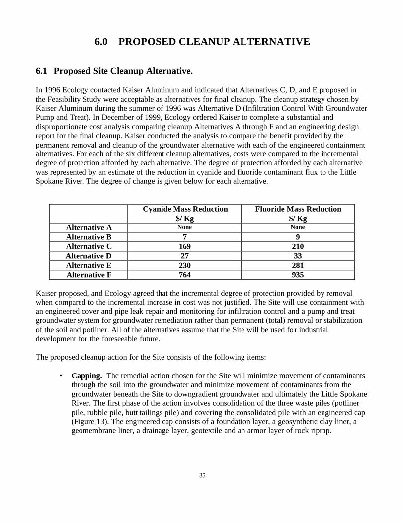
6.0 PROPOSED CLEANUP ALTERNATIVE 6.1 Proposed Site Cleanup Alternative. In 1996 Ecology contacted Kaiser Aluminum and indicated that Alternatives C, D, and E proposed in the Feasibility Study were acceptable as alternatives for final cleanup. The cleanup strategy chosen by Kaiser Aluminum during the summer of 1996 was Alternative D (Infiltration Control With Groundwater Pump and Treat). In December of 1999, Ecology ordered Kaiser to complete a substantial and disproportionate cost analysis comparing cleanup Alternatives A through F and an engineering design report for the final cleanup. Kaiser conducted the analysis to compare the benefit provided by the permanent removal and cleanup of the groundwater alternative with each of the engineered containment alternatives. For each of the six different cleanup alternatives, costs were compared to the incremental degree of protection afforded by each alternative. The degree of protection afforded by each alternative was represented by an estimate of the reduction in cyanide and fluoride contaminant flux to the Little Spokane River. The degree of change is given below for each alternative.
Cyanide Mass Reduction $/ Kg
Fluoride Mass Reduction $/ Kg
Alternative A None None
Alternative B 7 9 Alternative C 169 210 Alternative D 27 33 Alternative E 230 281 Alternative F 764 935
Kaiser proposed, and Ecology agreed that the incremental degree of protection provided by removal when compared to the incremental increase in cost was not justified. The Site will use containment with an engineered cover and pipe leak repair and monitoring for infiltration control and a pump and treat groundwater system for groundwater remediation rather than permanent (total) removal or stabilization of the soil and potliner. All of the alternatives assume that the Site will be used fo r industrial development for the foreseeable future. The proposed cleanup action for the Site consists of the following items:
• Capping. The remedial action chosen for the Site will minimize movement of contaminants through the soil into the groundwater and minimize movement of contaminants from the groundwater beneath the Site to downgradient groundwater and ultimately the Little Spokane River. The first phase of the action involves consolidation of the three waste piles (potliner pile, rubble pile, butt tailings pile) and covering the consolidated pile with an engineered cap (Figure 13). The engineered cap consists of a foundation layer, a geosynthetic clay liner, a geomembrane liner, a drainage layer, geotextile and an armor layer of rock riprap.
35
.-----'------"-----''------'----'-----~-~--__,_ __ _,_ __ -'--_---'-__ _c....-___ ,__ _ _,_ __ ~_---,
'
•
•
REfEBENCF; -~
.;.:;: •. -"S.---·
. · . . ::_. --<
--,·
~ t>NJ: ASSCCIA"'f'E;S ~It E!CiINEDS la!ltll!!tJl.m.ol-"""= .....,,'"'1?11 1'1HI -·--
- it--- ---•·
This l'l<>pp!ng • ..,..- i:a,,,pl Lt,d !,l!ll"ll ph<rt~lc ....thcdc ~ l'IR<tts; No;tJ cno. L ~ A~cy St~nd~~ .•. for ~ ~II.Ill' Of' 1•~ fl"DI'! p!,otcgr"l"~!1Y ,.,,,...,.... .• ;;.AUG,..,,
CllNlll..R lNTERVA!J 1 Ftl!!r
t Elll:9'TIHG <:Arel! llA.'JIH - UM!Cllmleuffl PIPING • ~.. RrrEREH~E "'· •
--='";:~--~-
•
IIIV!XI !Sll.EI] 11l~ llRN'T "':lll!T
C..n; j REVISION
Em~~ Pm,::;,n,1..!>£
- -- -- . . ~ .
~i:,~-. RUBllt£ PILE'f-.
, .... 'I •
-
EJL!:lfl!G IIIIIIITtRUl:i lllJ.
EXUTl/,13 ICIIITtRIICI lllJ.
ElUIT!fllj ICIIIHII - ~UA:ll !llT fJQUmJICI
OtsrlliCi CA'!Ci BM.!~
;-•,,~ ~"" -------'~- '.
IOl"PIIIIClll1m: 1.D:ATI!Jj CF EXI.Jruli Smlll SllO! <m: ;ilCi,
.Y!'imtMTt LIMITS CT J\IEU
' '. '. '.
~~ enlhlmrw. .,._ ..... ..__ ....... _ ... __ _ ... _ .. __ _ KAISER -~ ·=-·--ff:~< ---...... __ ,,. .. _ -·-•- ...... -..... -... --.. -·--~ .... -~ ··-----_,, ___ _ -
Ct.48' •01/16' JI ••II.a!' Qi<!D!IT,IIC<d
lll'IOIN'~•IIII' .D •:<a.CJ' ~JPL(
Cll'Ell 120' •• !/4• -IXll•:O llC~ ~ -= '" •11NC1.£Se-• II!" -.E: 1·~0· .-...__ <f:IW I tof!~ l1l CllllfNS>OH:! llM[ Cf!6<1m: (!'j(lO
- __.,,---- 00 liOT JC,Oll: n F w.,.,,.. --~·
m
ALUM/NU/14 MEAD WORKS
SPL CLOSURE FLAN o'l/TSTING CDNDITHlNS
---:-
Figure 13
MEAD Ei:lsi 2111 Maall, WA
WORKS. H<1-.1h "m• Ro<ld
SBl121-SC!17
--P-A-27721
_;
•
•
37
; .. ,.. ...... .,.
-·
!
' .! •
' --
!
!
'
~ ;E :,: r '" "'~];,, " ~ >O ~c ,c ZPl D ~ ~ --., ;:'- A r>~ >Z z
" I :1,. ~ ' I ru
'" '" ru ru
9',
' i
" I
~~ ~~ <! .
i~
< 0,:: ,. ·"er;:' ~== 0
• ! "" "l 0 ' :;o "r" :::. "- (/)
>
5 > e
~ •
C C
i • l
' ' I ~
• !
i ij
~· ;,. \.''_ i
1Ilii •[IP 1IH1
•
ii
ij i
' • ! '
I I
•1 di!
B ! ~ i
I I j i ' '
I , I I ii f ! l ,i " i ii l
I n . ' • I . .I
B a ' I ! ! l
' . ! I I I ' i !
11 l •
I
! !
" •· 00 C
" ru
~
~
•
"
•
< ;
j1<"' ·' ,-,~ ;. ..
" r j ·,'
.1 ,·,,-·
I• ;!. i {
;, '.., ,. , 1 , ···j lli_i;
~.,,....,. I t, ····,.:
_v; ' , ., I. p-- -- ...
-~---·
' '
;\i ,- \
•
/ ·' •
39
~-,
APPROXIMATE J!.l~CTJOf!.0£.. GROUNDWATER
FLOW
'
_!:XP!-~NATIO~
Hc- 60 Mon,torinq Well
~ Locat,ons of Butt Toil,ng, Rubble ancl Sf-'l f'ile:;
PROPOSED EXTRACTION
WELL (STOTAL)
Hc-,z 0
" 'ill"l.C'. Rose rn"P toke" lrom Adam, & <:la,k. Inc C,u,·,eyed Map,
Novomb~r R. 20ll0
-TI APPROXIMATE
EXTENT OF PROPOSED CAP
• tJ
t N
i Scole ;n Fe~t
25G ~00
PROPOSED TREATMENT
SYSTEM LOCATION
0HC-17
KAISER ALUMINUM - MEAD FACILITY
Figure 16 ALTERNATIVE 1
FOCUSED GROUNDWATER EXTRACTION
MFG, INC. ENVIRONMENfAL ,c,rnccs ANO ENCLNEERING

(Figure 14) The consolidated pile will have minimum slopes of five percent and a maximum slope of 3 horizontal to 1 vertical. Storm water will be controlled from the site. The storm water drainage system will minimize ponding and direct water to a single discharge location. Storm water will be controlled using grading, ditches and culverts. Grading of the site will consist of removing sumps, soil and asphalt of the temporary potliner storage area and covering the clean soil with asphalt (Figure 15). Kaiser completed the cap as an interim action under Ecology Order # DE 01 TCPIS – 2075 in November of 2001.
• Repair of Storm Water and Sanitary Sewer Lines. The leakage from pipes through the
contaminated soil column is considered to be one of the primary sources of groundwater contamination. Kaiser Aluminum completed an evaluation of sewer, steam return, water mains, and NPDES outfall lines in 2000. Several pipes near the contaminated soil area were found to have the potential to leak. A major leak was identified in the NPDES outfall line east of the potliner pile. Kaiser completed repair or slip lining of the leaky pipes during the summer of 2001. Kaiser will repeat the inspection of gravity and pressure piping using a ten year cycle. Any leakage discovered in the inspections will be repaired.
• Groundwater Pump and Treat. Groundwater pumping and treatment is a method used to
remove contaminated groundwater from the aquifer and clean it. The pump and treat system is constructed using a line of extraction wells perpendicular to the regional groundwater flow. These wells will be located down gradient of the area of highest contamination found in the uppermost transmissive zone (Zone A) of the aquifer (Figure 16). The highest cyanide, fluoride, and dissolved solids concentrations were observed in groundwater samples collected from the base of zone A. A pumping rate of 25 gallon per minute from five extraction wells will be used to supply contaminated groundwater to the treatment plant. The extracted groundwater will be treated using conventional chemical precipitation techniques. Bench-scale testing of various potential treatment technologies has indicated that chemical precipitation is the most effective means of treating and removing cyanide and fluoride from the groundwater. Both cyanide and fluoride will be removed using precipitation chemical reactions. Calcium chloride (CaCl12) will be added to precipitate fluoride from the water and ferrous iron from either ferrous chloride (FeCl12) or ferrous sulfate ( FeSO4) will be added to precipitate cyanide from the water. The iron precipitation of cyanide is preformed concurrently with the removal of fluoride. The expected cyanide and fluoride removal in the treatment system is given below.
Parameter
Concentrations
Flow Rate (gpm) 25 Influent Cyanide Conc. (mg/L) 90 Effluent Cyanide Conc. (mg/L) 1 Influent Fluoride Conc. (mg/L) 120 Effluent Fluoride Conc. (mg/L) 15
40
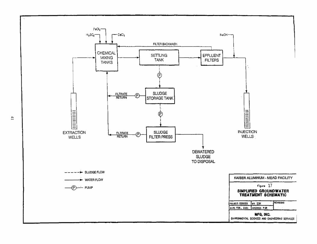
41
FeC1,-
H2S01l rCaCli
.,....._..._.,__
CHEMICAL MIXING TANKS
Fil TEA BACKWASH
SETILING TANK
I
I
$ i
-~ FILTRATE ~ RETURN
~~------i-®- SLUDGE STORAGE TANK
-------------~
EXTRACTION FILTRATE
WELLS RETURN ~=--l-®- SLUDGE
P FIL TEA PRESS
---- -~ SLUDGE FLOW
---.•~ WATER FLOW
~PUMP
NaOH-
I
~~~___.EFFLUENT~----''---~ . FILTERS
.. OEWATEREO
SLUDGE TO DISPOSAL
-'-
-------INJECTION
WELLS·
KAISER ALUMIN:UM • MEAD FACILITY
F!gurs 17 SIMPLIFIED GROUNDWATER TREATMENT SCHE'.MA'ttC
PROJECT: 0200~5 eY: ZGI< I R~!lOHS
D~~ m .. 1001 ci<tQlm: P.e I
MFQ, lNC, . ; £NY1RONMENTAL SClENCES ANO ENGINEE.RltiG SER-1CES I
Extracting groundwater at the 25 gallon per minute rate will result in approximately 9,800 pounds per year of cyanide and 13,100 pounds per year of fluoride being removed from the aquifer while minimizing the extraction of more dilute contaminated groundwater that may be pulled into the extraction area by using higher pumping rates. The treated groundwater will be re- injected into the aquifer using three re- injection wells located directly up gradient from the capped potliner pile. The sludge generated by the treatment plant is expected to be solid waste. The sludge collected from bench testing of the chemical precipitation treatment technology has been tested for dangerous waste characteristics and is a solid waste not a dangerous waste. A simple diagram of the system is given in Figure 17.
• Institutional Controls (soil and water) Institutional controls, consisteing of a restrictive
covenant, will be used to control exposure of future site workers to the contaminants beneath the cap as well as to maintain the integrity of the cap. The restrictive covenant will be filed with the property deed and will also limit development of the property and ban withdrawal of groundwater from the contaminated plume. The existing covenant will be made consistent MTCA.
• Long Term Monitoring and Cap Maintenance Plans. Long term maintenance plan and a
groundwater monitoring plan will be used to maintain and monitor the effectiveness of the cap and the groundwater pump and treat system. A financial bond will be established to assure continued operation of the extraction and injection wells, groundwater treatment plant, groundwater monitoring and repair of the cap.
The proposed cleanup action will meet the remedial action objectives of preventing potential receptors from coming into direct contact with or ingesting soil and groundwater containing cyanide and fluoride at levels exceeding cleanup criteria; and preventing or minimizing groundwater containing cyanide or fluoride exceeding cleanup criteria from migrating to the Little Spokane River. The cleanup strategy is two part and consists of source control project and a groundwater cleanup project. The direct contact contaminant pathway has been remediated using an engineered alternative — a DW cap. Spent potliner found at the plant site has been covered with a double lined dangerous waste cap. The contaminated soil found around the potliner pile has been removed and consolidated beneath the DW cap. The contaminated soil that exists at depth beneath the potliner pile and the DW cap will have institutional control placed on the deed of the property. The remedial action objective will be met as long as the cap is maintained and surface water is prevented from entering the potliner or contaminated soils. The second remedial action objective of preventing contaminated groundwater from entering the Little Spokane River will be met using a "pump and treat" groundwater treatment plant and pipe inspection and repair program. The treatment plant will remove cyanide and fluoride from the contaminated plume and reinject the water back into the aquifer up gradient of the plume head. The removal of water sources that mobilize cyanide and fluoride from the contaminated soil beneath the spent potliner pile was completed by repairing plant gravity and
42
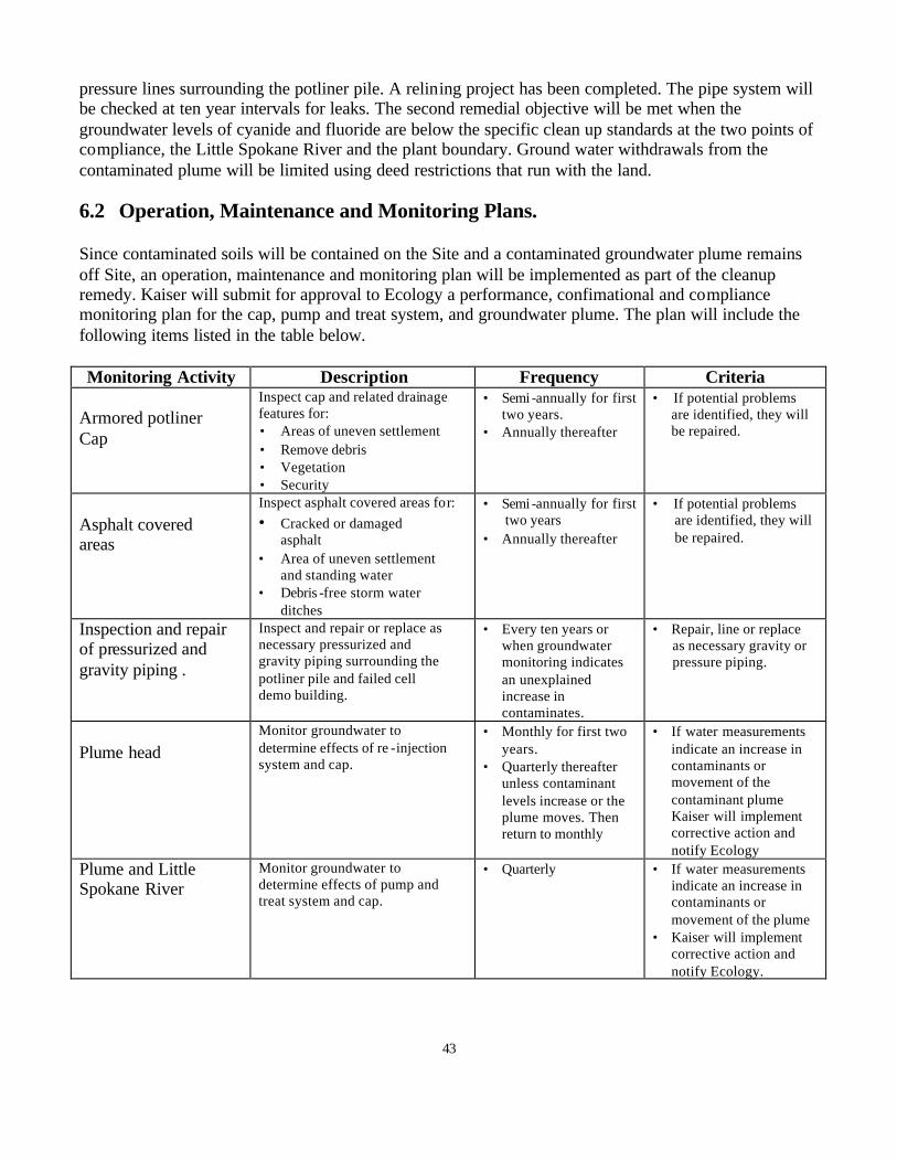
pressure lines surrounding the potliner pile. A relining project has been completed. The pipe system will be checked at ten year intervals for leaks. The second remedial objective will be met when the groundwater levels of cyanide and fluoride are below the specific clean up standards at the two points of compliance, the Little Spokane River and the plant boundary. Ground water withdrawals from the contaminated plume will be limited using deed restrictions that run with the land. 6.2 Operation, Maintenance and Monitoring Plans. Since contaminated soils will be contained on the Site and a contaminated groundwater plume remains off Site, an operation, maintenance and monitoring plan will be implemented as part of the cleanup remedy. Kaiser will submit for approval to Ecology a performance, confimational and compliance monitoring plan for the cap, pump and treat system, and groundwater plume. The plan will include the following items listed in the table below. Monitoring Activity Description Frequency Criteria
Armored potliner Cap
Inspect cap and related drainage features for: • Areas of uneven settlement • Remove debris • Vegetation • Security
• Semi -annually for first two years.
• Annually thereafter
• If potential problems are identified, they will be repaired.
Asphalt covered areas
Inspect asphalt covered areas for: • Cracked or damaged
asphalt • Area of uneven settlement
and standing water • Debris -free storm water
ditches
• Semi -annually for first two years
• Annually thereafter
• If potential problems are identified, they will be repaired.
Inspection and repair of pressurized and gravity piping .
Inspect and repair or replace as necessary pressurized and gravity piping surrounding the potliner pile and failed cell demo building.
• Every ten years or when groundwater monitoring indicates an unexplained increase in contaminates.
• Repair, line or replace as necessary gravity or pressure piping.
Plume head
Monitor groundwater to determine effects of re -injection system and cap.
• Monthly for first two years.
• Quarterly thereafter unless contaminant levels increase or the plume moves. Then return to monthly
• If water measurements indicate an increase in contaminants or movement of the contaminant plume Kaiser will implement corrective action and notify Ecology
Plume and Little Spokane River
Monitor groundwater to determine effects of pump and treat system and cap.
• Quarterly • If water measurements indicate an increase in contaminants or movement of the plume
• Kaiser will implement corrective action and notify Ecology.
43
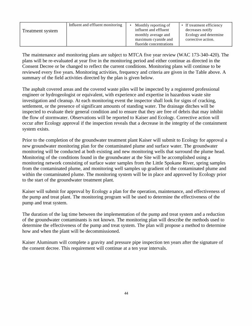
Treatment system
Influent and effluent monitoring • Monthly reporting of influent and effluent monthly average and maximum cyanide and fluoride concentrations
• If treatment efficiency decreases notify Ecology and determine corrective action.
The maintenance and monitoring plans are subject to MTCA five year review (WAC 173-340-420). The plans will be re-evaluated at year five in the monitoring period and either continue as directed in the Consent Decree or be changed to reflect the current conditions. Monitoring plans will continue to be reviewed every five years. Monitoring activities, frequency and criteria are given in the Table above. A summary of the field activities directed by the plan is given below. The asphalt covered areas and the covered waste piles will be inspected by a registered professional engineer or hydrogeologist or equivalent, with experience and expertise in hazardous waste site investigation and cleanup. At each monitoring event the inspector shall look for signs of cracking, settlement, or the presence of significant amounts of standing water. The drainage ditches will be inspected to evaluate their general condition and to ensure that they are free of debris that may inhibit the flow of stormwater. Observations will be reported to Kaiser and Ecology. Corrective action will occur after Ecology approval if the inspection reveals that a decrease in the integrity of the containment system exists. Prior to the completion of the groundwater treatment plant Kaiser will submit to Ecology for approval a new groundwater monitoring plan for the contaminated plume and surface water. The groundwater monitoring will be conducted at both existing and new monitoring wells that surround the plume head. Monitoring of the conditions found in the groundwater at the Site will be accomplished using a monitoring network consisting of surface water samples from the Little Spokane River, spring samples from the contaminated plume, and monitoring well samples up gradient of the contaminated plume and within the contaminated plume. The monitoring system will be in place and approved by Ecology prior to the start of the groundwater treatment plant. Kaiser will submit for approval by Ecology a plan for the operation, maintenance, and effectiveness of the pump and treat plant. The monitoring program will be used to determine the effectiveness of the pump and treat system. The duration of the lag time between the implementation of the pump and treat system and a reduction of the groundwater contaminants is not known. The monitoring plan will describe the methods used to determine the effectiveness of the pump and treat system. The plan will propose a method to determine how and when the plant will be decommissioned. Kaiser Aluminum will complete a gravity and pressure pipe inspection ten years after the signature of the consent decree. This requirement will continue at a ten year intervals.
44
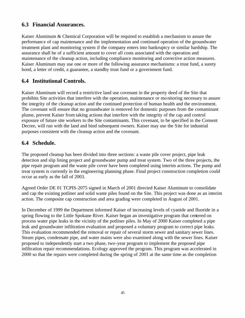
6.3 Financial Assurances. Kaiser Aluminum & Chemical Corporation will be required to establish a mechanism to assure the performance of cap maintenance and the implementation and continued operation of the groundwater treatment plant and monitoring system if the company enters into bankruptcy or similar hardship. The assurance shall be of a sufficient amount to cover all costs associated with the operation and maintenance of the cleanup action, including compliance monitoring and corrective action measures. Kaiser Aluminum may use one or more of the following assurance mechanisms: a trust fund, a surety bond, a letter of credit, a guarantee, a standby trust fund or a government fund. 6.4 Institutional Controls. Kaiser Aluminum will record a restrictive land use covenant in the property deed of the Site that prohibits Site activities that interfere with the operation, maintenance or monitoring necessary to assure the integrity of the cleanup action and the continued protection of human health and the environment. The covenant will ensure that no groundwater is removed for domestic purposes from the contaminant plume, prevent Kaiser from taking actions that interfere with the integrity of the cap and control exposure of future site workers to the Site contaminants. This covenant, to be specified in the Consent Decree, will run with the land and bind subsequent owners. Kaiser may use the Site for industrial purposes consistent with the cleanup action and the covenant. 6.4 Schedule. The proposed cleanup has been divided into three sections: a waste pile cover project, pipe leak detection and slip lining project and groundwater pump and treat system. Two of the three projects, the pipe repair program and the waste pile cover have been completed using interim actions. The pump and treat system is currently in the engineering planning phase. Final project construction completion could occur as early as the fall of 2003. Agreed Order DE 01 TCPIS-2075 signed in March of 2001 directed Kaiser Aluminum to consolidate and cap the existing potliner and solid waste piles found on the Site. This project was done as an interim action. The composite cap construction and area grading were completed in August of 2001. In December of 1999 the Department informed Kaiser of increasing levels of cyanide and fluoride in a spring flowing to the Little Spokane River. Kaiser began an investigative program that centered on process water pipe leaks in the vicinity of the potliner piles. In May of 2000 Kaiser completed a pipe leak and groundwater infiltration evaluation and proposed a voluntary program to correct pipe leaks. This evaluation recommended the removal or repair of several storm sewer and sanitary sewer lines. Steam pipes, condensate pipe, and water mains were also examined along with the sewer lines. Kaiser proposed to independently start a two phase, two-year program to implement the proposed pipe infiltration repair recommendations. Ecology approved the program. This program was accelerated in 2000 so that the repairs were completed during the spring of 2001 at the same time as the completion
45

of the capping project. A leak in the NPDES line was discovered in the spring of 2001 and repaired in May 2001. The pipe maintenance and repair program is now complete. The groundwater extraction and treatment system is currently in the engineering planning phase. The treatment plant design documents will be completed by April of 2002. After the Consent Decree is in place, the plant will be constructed. Completion of the construction of the water treatment plant could occur as early as the fall of 2003. The schedule for the site is given below.
46
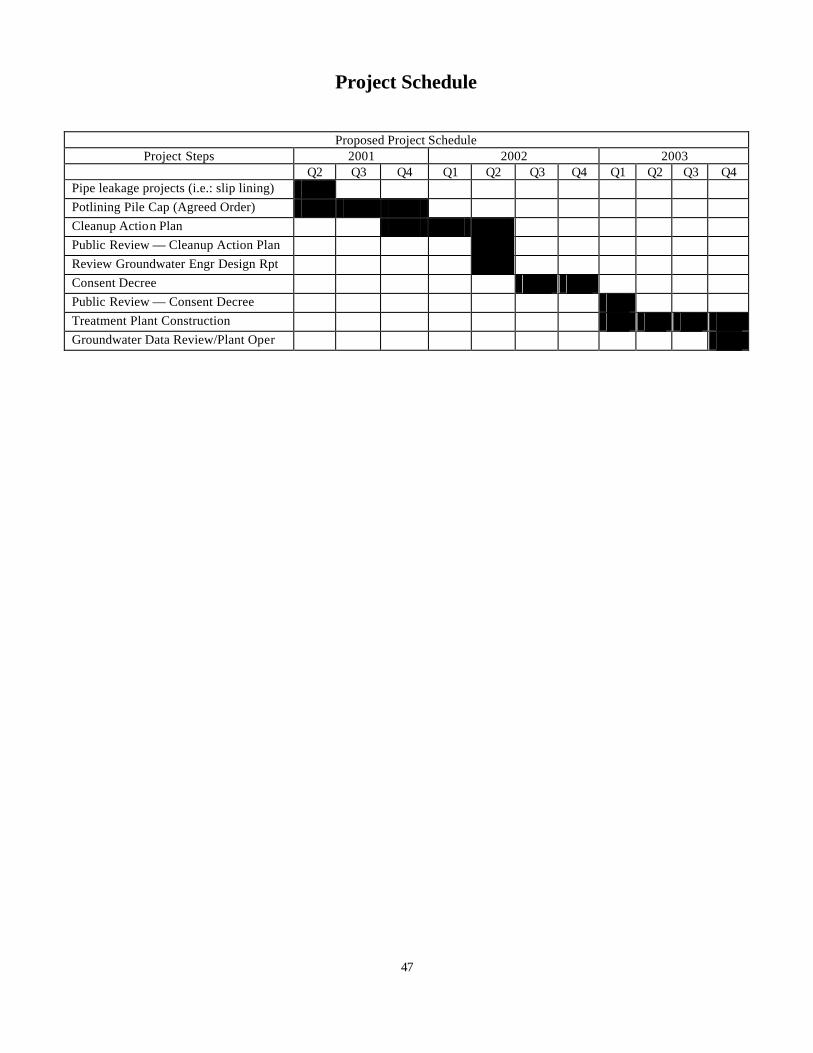
Project Schedule
Proposed Project Schedule Project Steps 2001 2002 2003
Q2 Q3 Q4 Q1 Q2 Q3 Q4 Q1 Q2 Q3 Q4 Pipe leakage projects (i.e.: slip lining) Potlining Pile Cap (Agreed Order) Cleanup Action Plan Public Review — Cleanup Action Plan Review Groundwater Engr Design Rpt Consent Decree Public Review — Consent Decree Treatment Plant Construction Groundwater Data Review/Plant Oper
47
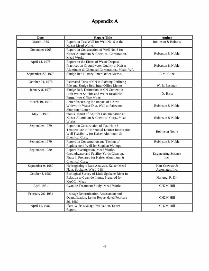
Appendix A
Date Report Title Author March 1955 Report on Test Well for Well No. 5 at the
Kaiser Mead Works Robinson & Roberts
November 1963 Report on Construction of Well No. 6 for Kaiser Aluminum & Chemical Corporation, Mead Works
Roberson & Noble
April 14, 1978 Report on the Effect of Waste Disposal Practices on Groundwater Quality at Kaiser Aluminum & Chemical Corporation., Mead, WA
Roberson & Noble
September 27, 1978 Sludge Bed History, Inter-Office Memo.
C.M. Cline
October 24, 1978 Estimated Tons of CN in Existing Potlining Pile and Sludge Bed, Inter-Office Memo W. B. Eastman
January 8, 1979 Sludge Bed, Estimation of CN Content in Both Water Soluble and Water Insoluble Form, Inter-Office Memo
D. Hirst
March 19, 1979 Letter discussing the Impact of a New Whitworth Water Dist. Well at Fairwood Shopping Center
Robinson & Noble
May 1, 1979 Status Report of Aquifer Contamination at Kaiser Aluminum & Chemical Corp., Mead Works
Robinson & Noble
September 1979 Report on Construction of Test Hole 8; Temperature in Horizontal Drains; Interceptor Well Feasibility for Kaiser Aluminum & Chemical Corp.
Robinson Noble
September 1979 Report on Construction and Testing of Replacement Well for Stephen W. Pope
Robinson & Noble
September 1980 Report Investigation, Mead Works, Groundwater and Facility Yards Cleanup, Phase I, Prepared for Kaiser Aluminum & Chemical Corp.
Engineering Science Inc.
September 9, 1980 Hydrogeologic Data Analysis, Kaiser Mead Plant, Spokane, WA J-948
Hart Crowser & Associates, Inc.
October 8, 1980 Ecological Survey of Little Spokane River in Relation to Cyanide Inputs, Prepared for KACC - Mead
Hartung, R. Dr.
April 1981
Cyanide Treatment Study, Mead Works CH2M Hill
February 26, 1981 Leakage Determination-Assessment and Quantification, Letter Report dated February 26, 1982
CH2M Hill
April 15, 1982 Plant-Wide Leakage Evaluation, Letter Report.
CH2M Hill
48

Date
Report Title
Author
December 1982 Groundwater Monitoring Summary Report, Kaiser Mead Works, Spokane, WA (Monitoring Summary through December 1982)
Hart Crowser & Associates
December 9, 1982 Evaluation of Storm Sewer Leakage Letter Tests, Report
CH2M Hill
1983 Groundwater Monitoring Summary Report, Kaiser Mead Works, Spokane, WA (Monitoring Summary through June 1983)
Hart Crowser & Associates
March 29,1983 Groundwater Contamination Potential from Uncovered Potlining Waste at KACC-Mead
Hart Crowser & Associates
1984 Groundwater Monitoring Summary Report, Kaiser Mead Works, Spokane, WA (Monitoring Summary through December 1983)
Hart Crowser & Associates
1984 Groundwater Monitoring Summary Report, Kaiser Mead Works, Spokane, WA (Monitoring Summary through June 1984)
Hart Crowser & Associates
1985 Groundwater Monitoring Summary Report, Kaiser Mead Works, Spokane, WA (Monitoring Summary through December 1984)
Hart Crowser & Associates
1985 Groundwater Monitoring Summary Report, Kaiser Mead Works, Spokane, WA (Monitoring Summary through July/August 1985)
Hart Crowser & Associates
August 1985 Cost-Effectiveness Study of Actions to Control Infiltration Prepared for Kaiser Aluminum & Chemical Corporation, Mead Works
CH2M Hill
1986 Groundwater Monitoring Summary Report, Kaiser Mead Works, Spokane, WA (Monitoring Summary through December 1985/January 1986)
Hart Crowser & Associates
1986 Groundwater Monitoring Summary Report, Kaiser Mead Works, Spokane, WA (Monitoring Summary through June/July 1986)
Hart Crowser & Associates
May 18, 1987 Groundwater Monitoring Summary Report, Kaiser Mead Works, Spokane, WA (Monitoring Summary, 1981 through January 1987)
Hart Crowser & Associates
1987 Groundwater Monitoring Summary Report, Kaiser Mead Works, Period January 1987 to July/August 1987.
Hart Crowser & Associates
March 21, 1988 Groundwater Monitoring Summary Report, Kaiser Mead Works, Period January 1988 to July 1988.
Hart Crowser & Associates
June 17, 1988 Groundwater Monitoring Summary Report, Kaiser Mead Works, Period July/August 1987 through February 1988.
Hart Crowser & Associates
49
Date Report Title Author 1988 Groundwater Sampling Results, Letter to
KACC Mead (September 1988 Sampling Results)
Hart Crowser & Associates
December 1988 Engineering Assessment Report CH2M Hill December 1988 Site Characterization Analysis Hart Crowser &
Associates May 1989 Review of Potential State ARARS For Kaiser
Aluminum & Chemical Corp. CH2M Hill
July 1989 Results of a GPR Survey at Kaiser Mead Plant
Williamson and Associates, Inc.
September 1989 Aquitard Well Installation Summary - KACC Mead Works.
Hart Crowser & Associates
September 25, 1989 Results of Unsaturated Zone Analyses, KACC - Mead Works
Hart Crowser & Associates
February 14, 1990 Groundwater Monitoring Summary Report, Kaiser Mead Works, Period July through December 1989.
Hart Crowser & Associates
August 28, 1990 June 1990 Aquitard Well Installation Summary, Upgradient of Potlining Pile, Kaiser Mead Plant
Hart Crowser & Associates
September 19, 1990 Groundwater Monitoring Summary Report, Kaiser Mead Works, Period January through June 1990.
Hart Crowser & Associates
May 21, 1991 Groundwater Monitoring Summary Report, Kaiser Mead Works, Period July through December 1990.
Hart Crowser & Associates
December 12, 1991 Groundwater Monitoring Summary Report, Kaiser Mead Works, Period January through June 1991.
Hart Crowser & Associates
September 1992 Groundwater Monitoring Summary Report, Kaiser Mead Works, Period July through December 1991.
Hart Crowser & Associates
February 1993 Feasibility Study for Cleanup Actions at the Kaiser Mead NPL Site.
RETEC
September 1993 Groundwater Monitoring Summary Report, Kaiser Mead Works, Period January 1992 through November 1992.
Hart Crowser & Associates
June 1994 Groundwater Monitoring Summary Report, Kaiser Mead Works, Period February 1993 through December 1993.
Hart Crowser & Associates
May 30, 1995 Cyanide Concentrations in the Little Spokane River 1981 - 1994
Hartung
November 1995 Ecological Survey of the Lower Little Spokane River in Relation to Cyanide Inputs 1995
Hartung
November 1995 Groundwater Monitoring Summary Report, Kaiser Mead Works, Period March 1994 through November 1994.
Hart Crowser & Associates
April 1997 1995 and 1996 Groundwater Monitoring Report.
Hart Crowser & Associates
50
Date Report Title Author April 3, 2000 Substantial and Disproportionate Cost
Analysis MFG, Inc.
April 21, 2000 Water Quality Monitoring Requirements Hart Crowser & Associates
May 2, 2000 Kaiser Mead Pipe Leak and Groundwater Infiltration Evaluation
MFG, Inc.
November 30, 2000 SPL Remediation Engineering Design Report, Kaiser Aluminum & Chemical Corporation, Mead, WA
MFG, Inc.
December 14, 2000 Technical Memorandum. Evaluation of Groundwater Extraction and Re-injection Alternatives Kaiser Mead Works
MFG, Inc.
February 22, 2001 Technical Memorandum. Basis for Groundwater Extraction Rate - Kaiser Mead Works
MFG. Inc.
November 15, 2001 Construction Completion Report. Kaiser Aluminum & Chemical Corporation SPL Remediation, Mead, WA
MFG, Inc.
51


