

EVALUATION OF HEAT TRANSFER COEFFICIENTS
WITH THERMOCAMERAPeter Magnusson
20022002

Date of last change Reference/Name of Presentation/SN 2
INTRODUCTION
Aim:Determine heat transfer coefficients
for use in cooling calculations to verify and improve the cooling effectiveness
[ ]KW/m2
wcoolingflosurface TTq
−=α
λα l
Nu⋅
=

Date of last change Reference/Name of Presentation/SN 3
INTRODUCTION
l The technique has been used since 1997 at ALSTOM Power to investigate heat transfer coefficients for tests at near engine conditions (500 - 700 deg C) and with engine parts
l More recently been used in scaled perspex models at room temperature

Date of last change Reference/Name of Presentation/SN 4
HIGH TEMPERATURE RIG
Temperature mapped with a thermocamera
Guide vane
Thermocouple

Date of last change Reference/Name of Presentation/SN 5
THERMOCAMERA
Thermovision 900 systemAGEMA 900SW/STSpectral response 2.0 – 5.6 micron

Date of last change Reference/Name of Presentation/SN 6
Transformerinput 220 V
electricalq&
SCHEMATIC DESCRIPTION
HeaterfoilPerspex wall
outbulk,Tm&
outsidesurface,TImpingement plate
Thermo cameragenerating a two dimension temperature field, Toutsidesurface lossq&
inbulk,Tm&
Model
Date of last change Reference/Name of Presentation/SN 7
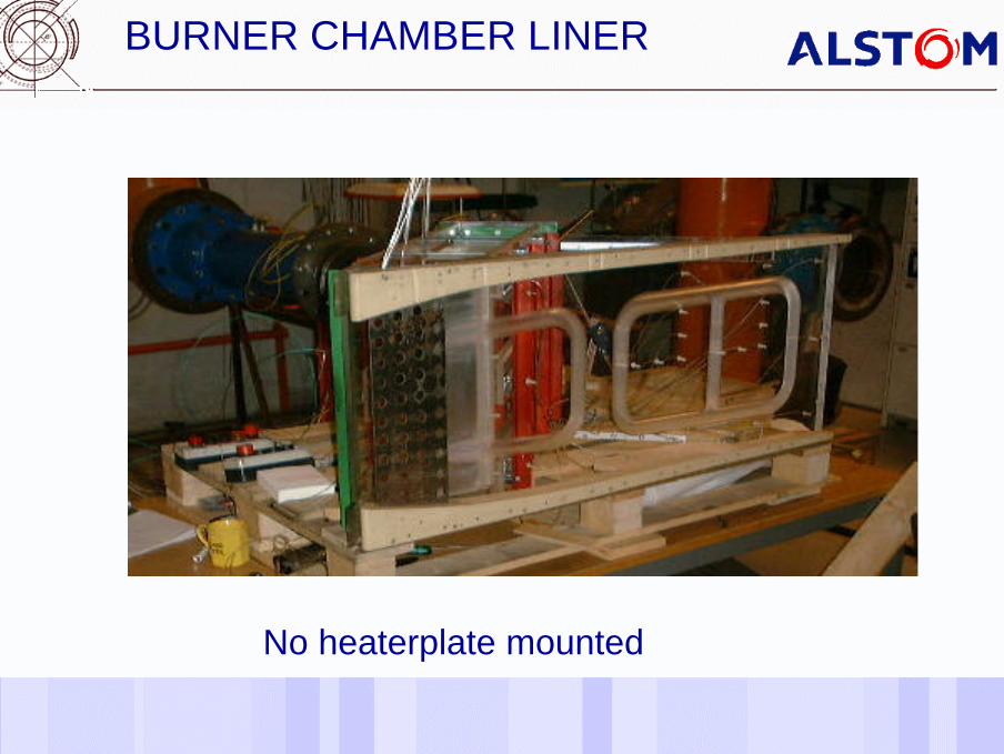
BURNER CHAMBER LINER
No heaterplate mounted

Date of last change Reference/Name of Presentation/SN 8
Thermo camera field
Resolution 10o x 5o at min, 1 m (176 x 87 mm)Number of pixels 200 x 136(this field ~400 x ~300 mm, 200 x 136 pixels)

Date of last change Reference/Name of Presentation/SN 9
Thermo camera field
A piece of the impingement cooled, Alfa number
Date of last change Reference/Name of Presentation/SN 10
Transformerinput 220 V
electricalq&
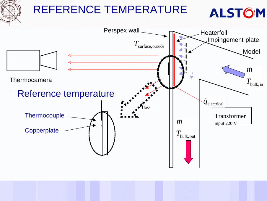
REFERENCE TEMPERATURE
HeaterfoilPerspex wall
outbulk,Tm&
outsidesurface,T Impingement plate
Thermocamera.
lossq&
inbulk,Tm&
Model
Thermocouple
Copperplate
Reference temperature

Date of last change Reference/Name of Presentation/SN 11
THEORETIC DESCRIPTION
Geometric and dynamic scaling
engine
model
ll
n =Alm c
µ&
=Re
Date of last change Reference/Name of Presentation/SN 12
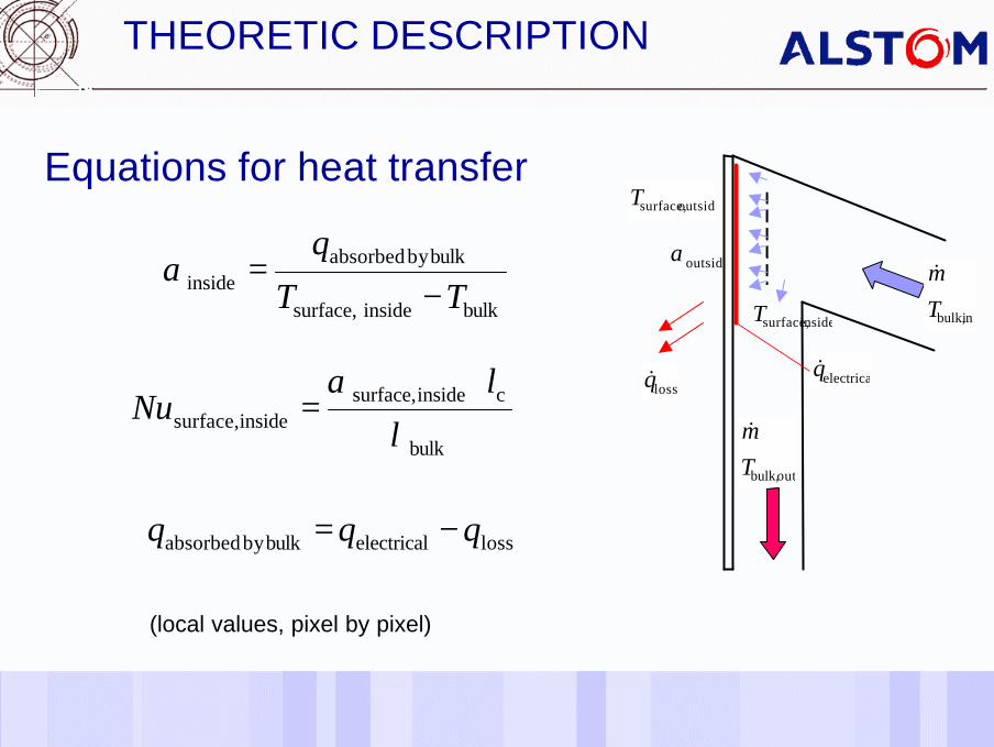
Equations for heat transfer
(local values, pixel by pixel)
THEORETIC DESCRIPTION
losselectricalbulkby absorbed qqq −=
bulkinside surface,
bulkby absorbedinside TT
q
−=α
bulk
cinsidesurface,inside,surface λ
α lNu
⋅=
electricalq&
outbulk,Tm&
outsidesurface,T
inbulk,T
m&
insidesurface,T
lossq&
outsideα

Date of last change Reference/Name of Presentation/SN 13
Losses to ambient
(local values, pixel by pixel)
THEORETIC DESCRIPTION
( )ambientoutsidesurface,outsideloss TTq −⋅= α
ambientT Insulation
Heaterplate
ambientoutsidesurface,
electricoutside TT
q−
=αelectricalq&
outbulk,T
m&
inbulk,T
m&
lossq&
outsideα
outsidesurface,T
insidesurface,T
100 %5 - 10 %

Date of last change Reference/Name of Presentation/SN 14
Final evaluation
(local values, pixel by pixel)
THEORETIC DESCRIPTION
ambientT
electricalq&
outbulk,T
m&
outsidesurface,T
inbulk,T
m&
insidesurface,T
lossq&
outsideαplateperspex
thicknesslossoutside,surfaceinsidesurface, λ
lqTT +=
thicknessl
bulkinsidesurface,
bulkby absorbedinside TT
q
−=α
( )( )( ) c
bulkbulkinsidesurface,
ambientoutsidsurface,outsideel lTT
TTqNu e ⋅
⋅−−⋅−
=λ
α

Date of last change Reference/Name of Presentation/SN 15
One remarkIf there are large temperature fluctuations over the heater area the power is not uniform distributed One exampleNickel-iron foil40 oC 1.193 ohm60 oC 1.297 ohm
THEORETIC DESCRIPTION
Date of last change Reference/Name of Presentation/SN 16
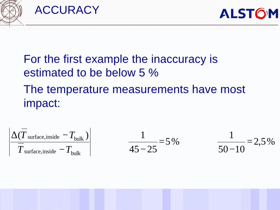
For the first example the inaccuracy is estimated to be below 5 %The temperature measurements have most impact:
ACCURACY
%5,21050
1%5
25451)(
bulkinsidesurface,
bulkinsidesurface, =−
=−−
−∆TTTT
Date of last change Reference/Name of Presentation/SN 17
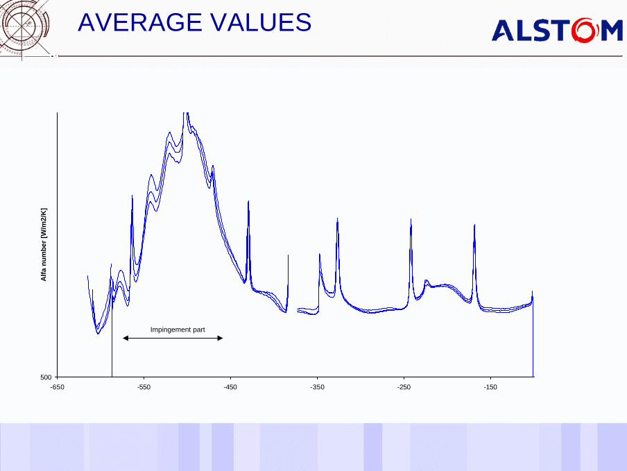
AVERAGE VALUES
500-650 -550 -450 -350 -250 -150
Alf
a n
um
ber
[W
/m2/
K]
Impingement part

Date of last change Reference/Name of Presentation/SN 18
TURBINE BLADE INTERNAL COOLING

Date of last change Reference/Name of Presentation/SN 19
TURBINE BLADE INTERNAL COOLING

www.alstom.com


