

EXAMINATION OF THE PRESSURE TUBE RUPTURE AT PICKERING NGS ‘A’
UNIT 2, FUEL CHANNEL G16
-- TECHNICAL REPORT --
Report No. 84-08-09-1 Date: March 1984
Prepared By
______________________ Ross E. Lewi s
Team Manager & Leader
______________________ Stavros Corbett
Assistant Manager
______________________ Jenni fer Suddard
Research Special ist
______________________ Bruno Torcia
PS Engineer/Analyst
______________________ Leo Fortey
Graphic De sign & PS PRO
______________________ Ali Andrew
Logic Analyst

INTRODUCTIO N TO THE EXAM INATIO N OF THE PRESSURE TUBE RUP TURE AT PICKERING NGS ‘A’ UNIT 2, FUEL
CHANNEL G16
Pickering Nuclear Generating Station, located approximately 35 km east of Toronto, is
home to the first 8-unit CANDU-PHW (Pressurized Heavy Water) Reactors, assembled
and initially operated by Ontario Hydro. Completed in 1973, this multi-unit station
produced more electricity at the time than any other nuclear power facility in the world.
There have been many nuclear reactor systems tested, but the PWR (Pressurized Water
Reactor) and the PHWR (Pressurized Heavy Water Reactor, used at Pickering NGS),
have been the most successful in terms of performance and economic viability.
Figure 1. Aerial photo of the Pickering Nuclear Generating Station.

The ever-increasing need for power in a society where the consumption of
electricity always comes in great demand is, alone, of an importance significant enough
to demand the continuing maintenance and operation of the Pickering Nuclear Generating
Station. Several other advantages can be noted regarding the plant’s usage of fuel and
relative operating costs. For instance, the reactor uses natural uranium which is found in
abundance. In addition to a simple fuel assembly, coupled with a high power output
relative to the unit amount of mined uranium required, translates into a low fuelling cost
for the facility. The design of the CANDU-PHW reactors also allows for the replacement
of spent fuel without having to reduce energy output. The Pickering NGS reactors do,
however, require constant maintenance of the complex fuel handling systems, the high
cost of which has recently been under public scrutiny. However, the investment costs
required in order to achieve optimum performance levels are minute in comparison to the
amount of electricity capable of being generated by the plant. Pickering’s plant
operations are structured around automated processes, allowing operators and engineers
adequate time to perform maintenance and inspection tasks. In addition, the inherent
design of the PHW reactors makes it virtually impossible for an accidental situation to
transpire into a reactor meltdown, making the plant a safe and reliable choice as an
electricity generating neighbour for the concerned public.
Figure 2.
The successful operation of a CANDU reactor is dependent on a multi-faceted set of systems that must all be mutually taken into consideration. An extensive knowledge of the major factors shown in the diagram is required in order to be able to make informed decisions regarding the present state of a CANDU reactor and its coupled systems. In this way, knowledgeable decisions can be made in case of unexpected accidents.

Situational Analysis of the Events Surrounding the P2 G16 Failure, August, 1983
Introduction
The CANDU (Canada Deuterium Uranium) reactor consists of a horizontally
mounted vessel approximately 6 meters in diameter termed the calandria, sealed at each
end by plates called end shields. Inside the Pickering NGS Unit A reactor, 390 fuel
channels manufactured from a Zirconium-Niobium alloy 4.3mm thick and 104 mm in
diameter, span the entire length of the calandria. As shown in the figure below, the
pressure tubes are inserted into slightly larger calandria tube, with Garter Spring
(annulus) spacers separating the two tubes every 1.5 to 2 meters.
Figure 3. The diagram above shows only 3 fuel channels. The CANDU reactor at Pickering NGS contains 390 of these tubes.
Accident Definition/Description
The loss of coolant accident at Pickering NGS Unit A has been assessed by the
Ontario Nuclear Safety Review (ONSR) as an accident of a magnitude great enough to be
considered extreme. The contiguous circumstances embodying the rupture of the G16
pressure tube led to a complete loss of reactor power resulting in reactor shutdown.
The accident, resulting in an abrupt loss of heavy water coolant from the primary heat
transport system1, can be separated into three distinct phases. The first 20 seconds of the
rupture is referred to as the prompt phase, characterized by highly unstable and
uncontrollable fission events involving release of large amounts of energy. The
consequence of these short-timed events was the termination of the fission chain reaction
due to the excessive amount of thermal and mechanical damage inflicted upon the reactor
core.
During the short term phase (following the coolant excursion), the rates of positive
reactivity related to the inability of the heat transport system to remove the excess decay
heat from the UO2 pellets had begun to decrease. The continuous removal of stored heat
from the reactor core, enhanced by the injection of additional coolant lead to the final
stage of the accident, termed the long term stage. At this point, essentially all of the
uncontrollable fission events have been terminated while maintaining an ongoing ejection
of coolant, creating a ‘heat sink’ that removed excess fission products from the reactor
core.
The critical factors that determined the resulting damage and consequences of the
accident all occurred during its initial stages following the rupture of the pressure tube.
The extent of the release of fission products leading to immediate transient mass and
energy transfers in the core had the greatest impact on the duration of subsequent events.
1 Field,G.J. Current Status of Fuel Channel Examinations Following the P2 G16 Failure in August, 1983.Nuclear Systems Department, Ontario Hydro, Toronto. 1985. p. 12.2

COMMENTS ON LOCA TIMELINE At approximately 11:36:30, the operators understood the problem and realized the
inherent problems with maintaining pressure control against the shrinkage caused by the
simultaneous cool-down and power reduction and the leak.
40 minutes after detecting the leak, the operators effectively reduced the reactor power to
a FP 2 percent and initiated a responsible action in performing a cool-down.
Reduction of the HT pressure helped minimize the losses due to the rupture and thus
reduced the leakage rate and allowed some measure of control to be re-established.
Approximately, 85 minutes after the leak became apparent, the operators had the unit
safely shut down, with the HT system on shutdown cooling and thereby stabilizing the
unit’s loss of coolant accident.
LOSS OF COOLANT ACCIDENT TIMELINE (w.r.t Transient) (Times in italic mean approximate time, i.e not taken from DCC1 or 2 systems)
11:06:00 refueling of G3 reactor channel completed 11:09:31 alarms tripped on several HT pump-gland supplies because of low flow, followed by low pressure alarm in HT system-pressurizing pump-discharge header Operator noted excessive feed to both loops and rapidly falling level in HT storage tank Unit 3 First Operator came to aide the Unit 2 First Operator An Operator sent to prepare Unit 3 for inter-unit D2O transfer Using only one pressurizing pump, HT system was stabilized after upset 11:19 Inter-unit D2O transfer from Unit 3 started Manual setback initiated then terminated at 81 percent FP when HT system pressure fell below control set-point
Second pressurizing pump was probably turned on temporarily to try and restore pressure control Two more manual set backs reduced reactor power to 53 percent FP Operators decided to carry out a power reduction at 0.05 percent FP/s Operators prepared for shutdown, switching from Unit Class Power Supply to System Service Class IV Power Supply 11:27 Cool-down initiated at 0.7 degrees Celsius/min eighteen minutes after rupture 11:28 19 minutes after the rupture, the fourth power change terminated with reactor power at 43 percent. 11:29 Another power reduction was initiated at .05 percent FP/s. Low pressure alarms for HT pump-gland-supply and HT pressurizing pump discharge header continued to cycle in and out for the next few minutes. ROH pressure fell below 8.5 MPa (g) (AN1018 set-point) at about 23 minutes after the first alarm. 11:32:30 The cool-down was terminated. Unit 3 Operator responsible for HT, was given then given the authorization to reduce HT system pressure. 11:34:30 At about 25 minutes, the ROH pressure set-point was apparently readjusted to 8.1 MPa (g) (see Figure 2). At this time, the reactor power had been reduced to approximately 32 percent FP; it was held at this level for a couple of minutes. 11:36:30 Cool-down was “restarted at a rate of 2.8 C/min, and a third power reduction (sixth power change) at 0.05 percent FP/s (over an increment of 10 percent) was started. HT pump gland low flow and pressurizing pump discharge header low pressure annunciations cycled in and out. In order to reduce the leak rate and regain pressure control, it appears that the ROH pressure set-point was reduced to 5.7 MPa (g) about 31 minutes into the event. Shortly after this, the third power reduction stopped at 21.6 percent FP.”2
2 Ho, Steve. Simulation of Pickering NGS; A PHT Response Following Pressure Tube Rupture In Channel G16 of Unit 2. Report No. 84083, Nuclear Systems Department, Ontario Hydro, Toronto. Feb. 1985.

11:43 Cool-down was again turned off and reactor power was reduced at 0.05 percent FP/s. 11:43:31 18 percent FP, 'cool-down was restarted. 11:44 Manual setback initiated by the operators with power falling to 2 percent as a result Just about then, reactor power dropped to 10 percent FP, and turbine was activated. “Shortly after the setback terminated the large steam discharge valves opened, replacing the turbine as the heat sink during cool-down.”3
11:49 ROH pressure set-point appears to have been reduced to about 3.9 MPa (g) with cool-down continuing as reactor power was reduced to about 1.2 percent FP. 11:58 D20 recovery pump was started. 12:01 Inter-unit transfer from Units 3 and 4 was stopped. 12:05 “Feed was noted to be going preferentially to the south loop (the first definite indication that the HT loop interconnect valve was closed). Over the next half-hour, inter-unit D20 transfer was continued intermittently, the D20recovery pump was operated intermittently and HT system pressure was reduced further. 12:35 “Main HT pumps were shut down and the HT system was placed on shutdown cooling. All inter-unit D20 transfers were stopped shortly thereafter.”3
12:38 The HT pressure was lowered as far as possible, and the south loop was ensured to be full of D20. “North loop pressure dropped to 50 kPa (g) at this time, while the south loop pressure was controlled at approximately 200 kPa (g). Feed flow to the south loop, as read from the panel indicator, was noted at a steady-rate of 5 kg/s.”3
END OF TRANSIENT
3 Ho, Steve. Simulation of Pickering NGS; A PHT Response Following Pressure Tube Rupture In Channel G16 of Unit 2. Report No. 84083, Nuclear Systems Department, Ontario Hydro, Toronto. Feb. 1985.

KT SITUATIO NAL ANALYSIS
The rupture of the G16 pressure tube (near the core centre) is considered to be the
initiating event that ultimately led to shutdown of the reactor. A 2 meter long crack was
found near the centre of the tube, in addition to blisters of zirconium hydride alongside
the rupture in which the chemical heat produced from the oxidation of zirconium alloys
was added to the fission heat produced by the molten fuel. A situational analysis of the
problems faced by operators during and after the accident is shown in Table 1. Each
problem has been measured against three criteria, rated from low to high, involving the
urgency of the situation, its potential for growth, and the overall seriousness of the
problem. The type of analysis needed to correct the problem is then determined from the
type of problem itself and the rating of each criterion.
Table 1 Kepner-Tregoe Situational Analysis of the pressure tube (P2 G16) rupture at Pickering NGS, Unit 2. Continued on next page.
Problem # Problem Timing Trend Impact Process 1 Hydrogen Pickup: The oxidation of the Zirconium
Alloys in presence of water produces deuterium, whose solubility results in oxide deposits.
M H H PA
2 Accumulation of Hydrogen: Concentrations ranging from 20 to 50 ug/ g of Zr creates precipitation of zirconium-hydride). Under large tensile stresses, hydrides can cause the metal to crack.
L H M DA PPA
3 Formation of Blisters: • very large concentrations of hydrogen, about 350 ug/g Zr, blisters zirconium hydride can form. Cracks will appear in the metal if the blisters get large enough. This was one of reasons for the pressure tube rupture (P2 G16) Pickering U-2).
H H H DA PPA
4 When the pressure tube comes into direct contact with a calandria tube, blister formation increases at a greater rate.
H H H DA
5 Pickering’s large core size makes if difficult to insert negative reactivity fast enough in early stages of the accident into a practical moderator dump port arrangement.
L M MPA DA PPA
6 Following a moderator dump, the volume of coolant that has to be pumped back into the calandria is time consuming, limiting the actions available, assuming the xenon poison transient does not slow the rate of fission fast enough.
H H H DA PPA

Problem # Problem Timing Trend Impact Process 7 Volumetric expansion of pressure tubes: Prolonged
exposure to radiation of the Zirconium-Niobium tubes produces a continuous expansion from which the metal does not recover even after recovery of thermal and pressure effects on the tube.
L M H PPA
8 Radiaion Creep and Sag: Due to permanent volumetric expansion, the pressure tube and calandria tube come into contact. L H H PA
PPA
9 Garter springs (annulus spacers) are found in a location that is not their original design location, resulting in contact between pressure and calandria tubes.
M H H PA PPA
10 The replacement of Zirconium-2 pressure tubes in older reactors with Zirconium – 2.5% Niobium pressure tube to reduce tendency for oxidation to occur.
L M H PA PPA
11 An increase in the number of annulus spacers, in order to increase support along the pressure tube length
L M H PA PPA
12 Dissolved oxygen content in must be kept at low concentrations. A minimum of 3ml / kg of dissolved deuterium is required in order to this to occur
M H H PA DA
13 Trace oxygen amounts are needed in the annulus gas system in order to maintain an oxide layer outside of the fuel channels, reducing oxidation.
M M M PA PPA
14 Increased radiation fields due to the deposition of unwanted materials in the core over time, decreasing the heat transfer.
M H H PA PPA
15 An increase in the deposition of unwanted materials (‘crud’) on components not in the core, such as the steam generator.
M H M PA PPA
16 Reduce the amount of magnetite in the heat transport systems, a major corrosion product containing Co-60. Lower amounts of magnetite deposits in a reactor reduce unwanted radiation fields.
M M M PA PPA

Problem Analysis of Events Surrounding the P2 G16 Failure, August, 1983
In real life situations there are many causes to the problem. In the case of the rupture of
pressure tube G16, there are many causes that could have resulted in the tube rupture, see
Fig. 1. Some of the causes to the problem are trivial, but the main focus is on the vital
causes to the problem. Our design team has decided to further the analysis into those
causes to which are vital.
Fig 1: Cause and Effect Diagram shows all the possible causes for the rupture in pressure tube G16.
What is the Fault? The problem was that the pressure tube in channel P2G16 ruptured resulting in a loss of
coolant in the heat transport system (HTS). When analyzing the problem it is best to
follow a heuristic approach to solving the problem. In order to accomplish this goal, the
distinctions between what is the problem? and what is not the problem?
Once the distinction is made, a troubleshooting technique can be performed to determine
the cause of the problem. In Fig.1, A Kepner-Tregoe (KT) Problem Analysis chart is
shown to determine the cause of the rupture in the P2G16 pressure tube in Pickering A
reactor.

IS IS NOT DISTINCTION CAUSE What
Where
When
Extent
Fig.1: KT Problem Analysis Chart
Therefore from the KT chart, the main causes of the rupture in the pressure tube are that
the garter springs were not evenly spaced at every 1.5 to 2 meters along the channel. Also
the pressure tube and calandria tube had been in contact for four to five years prior to
failure, where the crack occured. With the combination of high temperature and
hydrogen/deuterium contents the pressure tube was weakened and a crack was created
initially 11 cm long. This crack grew to about 2 meters long due to the blisters along the
contact surface, and the end result was a loss of coolant of the primary heat transport
system.
Identify:
A 2meter crack in the pressure tube
A crack in the other channels
Different location in the reactor
Check if the pressure tube was in contact with the calandria tube: Yes
Locate:
In fuel channel G16 of Unit 2 at PNGS
At another unit at PNGS or another nuclear plant
Different reactors
Check if the garter springs were evenly spaced: No
Timing:
11:09:31 on August 1st, 1983
At night Different times of the day
Check operation of pressure tubes day vs. night: No difference
Magnitude:
Loss of heavy water coolant from PHTS
A nuclear core meltdown
An event that can be safely controlled
Check to see if rupture caused any harm: No injuries and the loss of coolant was contained

Description of the Causes to the Problem
The pressure tube and calandria tube are separated by an annulus gas (CO2) and
supported by garter springs located at every 1.5 to 2 meters along the channel. The
purpose of the garter springs is to keep the pressure tube supported and concentric in the
calandria tube. The garter springs prevents the sag of the pressure tube, which results in
the contact of both tubes and leads to fretting (thinning) of the pressure tube. Also, it
prevents heat transfer from the hot pressure tube to the cold calandria tube which can
result in blisters (high concentration of hydrogen and deuterium in contact surface).
The rupture of the pressure tube in channel G16 of Unit 2 was a result of two garter
springs that were not in the design location and allowed the outlet half of the pressure
tube to sag into contact with the calandria tube. Based upon analysis of the calandria
tube, it was concluded that the pressure tube and calandria tube had been in contact for
nine to eleven years prior to failure. The blisters D to E where the crack initiated did not
occur until four or five years before failure (see Fig.2).
Figure 2: Blisters seen on P2G16 Pressure Tube (C.J. Field, 12.3) The pressure tubes from Pickering A, Unit 2 and 3 consisted of Zircalloy 2 (Zr. 2). It had
been known for several years that the material, Zr. 2 fails at high temperature gradients

due to the formation of blisters. The extreme temperatures could only be reached by the
contact of the pressure tube and the calandria tube.
Decision Analysis of Events Surrounding The P2 G16 Failure, August, 1983
The operator prepared Unit 3 for inter-unit D20 transfer, which stabilized the heat
transport system. Pressurizing pump was turned on to restore pressure control. Within
forty minutes of detecting the leak the reactor power had been reduced from a hundred
percent full power to two percent power. After forty-five minutes the operator had Unit 2
safely shutdown by having the shutdown cooling system in place (see definition). When
the reactor power was reduced to 10 percent the operators tripped the turbine and large
steam discharge valves were opened to relieve the turbines as the heat sink.
Comment on Operator’s Decision The first safety system (SDS1) is to drop the rods into the reactor to shut down the
reaction. The operators did not utilize any of the special safety systems which would have
shutdown the reactor. If the operators had left the system, the pressure would have
dropped gradually and the safety systems would have operated. Another important
shutdown system called Emergency Coolant Injection (ECIS) works to stabilize the
pressure of the heat transport system where the break is located (see definition).

1.3 Definitions Shutdown cooling system: When the reactor power is brought down to 2% full-power,
the heat transport coolant is sent into heat exchangers once it exits from the inlet/outlet
headers.
Emergency Coolant Injection System: The emergency coolant injection system (ECIS)
protects the fuel and heat transport system boundary when normal cooling fails. Its
purpose is to refill the heat transport system and keep it full after a loss of coolant
accident (LOCA). This sets up an alternative heat flow path for removing decay heat.
C.J. Field. Current Status of Fuel Channel Examinations Following P2 G16 Failure in August 1983. Paper for Presentation at 1985 CNS Conference. Ottawa: June 1985. Ho, Steve et al. Design and Development Simulation of Pickering NGS A PHT Response Following Pressure Tube Rupture in Channel G16 of Unit 2. Nuclear Systems Department: Report No. 84083 February 1984. G.L. Brooks. CANDU Origins and Evolution-Part 3-5.2001 February.

ANALYSIS OF HO W TO PREVENT FUTURE FAULTS
Analyzing the sequence of events that occurred in Pickering Nuclear Generating
Station prior to the rupture of a pressure tube, it is seen that a combinations of failures
lead to the rupture of a pressure tube. This failure resulted in an abrupt loss of heavy
water coolant from the primary heat transport system allowing the reactor to over heat.
Failures that occurred leading up to rupture of pressure tube:
1. Hydrogen Pickup: The oxidation of the Zirconium Alloys in presence of water produces
deuterium, whose solubility results in oxide deposits.
2. Accumulation of Hydrogen: Concentrations ranging from 20 to 50 ug/ g of Zr creates precipitation of zirconium-hydride). Under large tensile stresses, hydrides can cause the metal to crack.
3. Formation of Blisters: very large concentrations of hydrogen, about 350 ug/g Zr,
blisters zirconium hydride can form. Cracks will appear in the metal if the blisters get large enough.
4. When the pressure tube comes into direct contact with a calandria tube, blister formation increases at a greater rate
5. Pickering’s large core size makes if difficult to insert negative reactivity fast enough in
early stages of the accident into a practical moderator dump port arrangement
6. Following a moderator dump, the volume of coolant that has to be pumped back into the calandria is time consuming, limiting the actions available, assuming the xenon poison transient does not slow the rate of fission fast enough.
7. Volumetric expansion of pressure tubes: Prolonged exposure to radiation of the
Zirconium-Niobium tubes produces a continuous expansion from which the metal does not recover even after recovery of thermal and pressure effects on the tube.
8. Radiaion Creep and Sag: Due to permanent volumetric expansion, the pressure tube and
calandria tube come into contact
9. Garter springs (annulus spacers) are found in a location that is not their original design location, resulting in contact between pressure and calandria tubes.
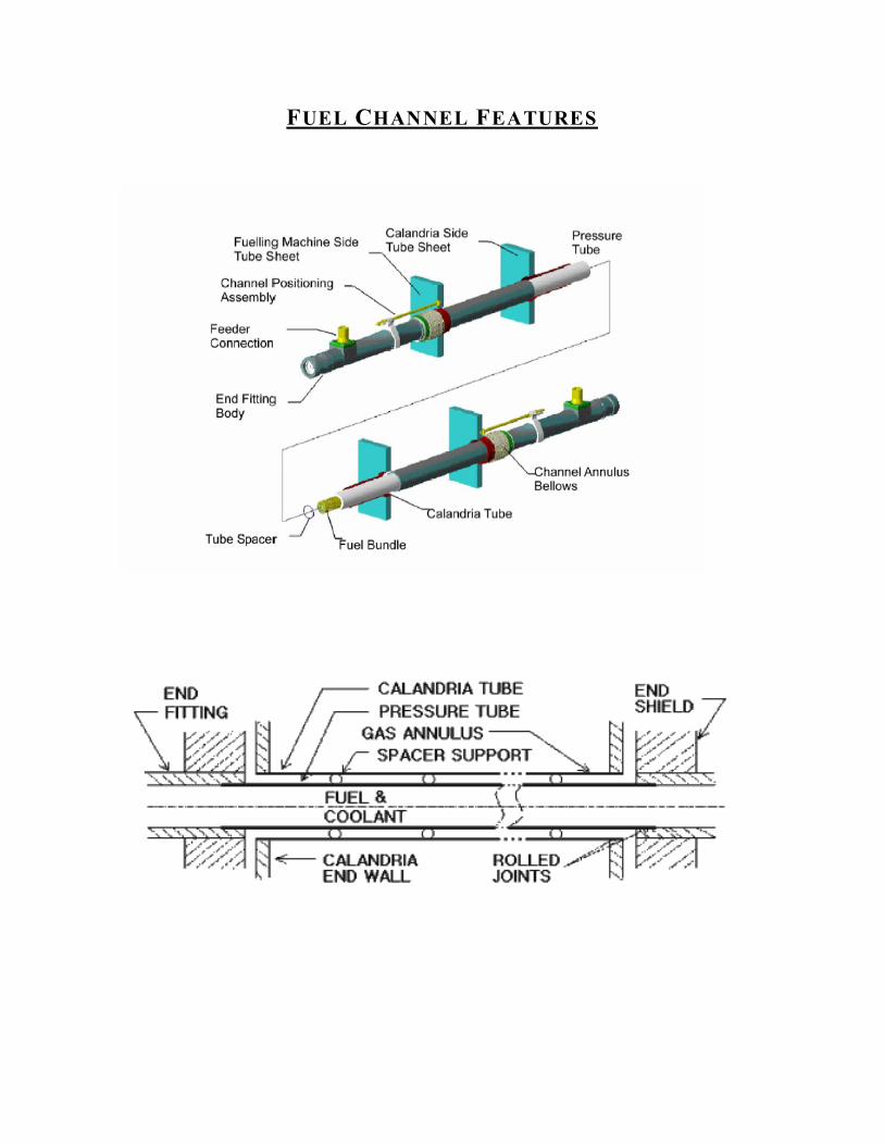
FUEL CHANNEL FEATURES

Kepner-Tregoe Potential Problem Analysis (PPA):
Potential Problem Possible Causes Preventive Action Contingent ActionsHydrogen Pickup: The oxidation of the Zirconium Alloys in presence of water produces deuterium, whose solubility results in oxide deposits
Deuterium build up allowed oxide deposits into pressure tube
Inspect pressure tube regularly for oxide deposits
Use different material for pressure tube such as Zirconium Niobium
Accumulation of Hydrogen:Concentrations ranging from 20 to 50 ug/ g of Zr creates precipitation of zirconium-hydride). Under large tensile stresses, hydrides can cause the metal to crack.
Accumulation of Hydrogen inside the pipe caused the metal to crack
Check hydrogen levels and inspect pressure pipe regularly for cracks
Install sensors to monitor hydrogen levels in pressure tube
Formation of Blisters: •very large concentrations of hydrogen, about 350 ug/g Zr, blisters zirconium hydride can form. Cracks will appear in the metal if the blisters get large enough
Blisters formed on the pipe due a very large concentration of hydrogen weakening the metal
Inspect pressure tube regularly for blisters
Install sensors to monitor for hydrogen deposits on pressure tube, replace pressure tube if blisters occur
When the pressure tube comes into direct contact with a calandria tube, blister formation increases at a greater rate
Spacer supports shifted allowing the calandria tube and pressure tube to come in contact
Monitor spacers between calandria tube and pressure tube regularly
Install more spacers and install sensors to monitor location of spacers between the calandria tube and pressure tube
Pickering’s large core size makes if difficult to insert negative reactivity fast enough in early stages of the accident into a practical moderator dump port arrangement
Core is too large to effectively insert negative reactivity
Make core easily accessible to effectively insert negative reactivity incase of an emergency
Change reactor design to incorporate negative reactivity dispensers In case of an emergency

Following a moderator dump, the volume of coolant that has to be pumped back into the calandria is time consuming, limiting the actions available, assuming the xenon poison transient does not slow the rate of fission fast enough
Coolant pump is inadequate and too slow to cool the reactor effectively
Install larger pump or install more pumps to effectively cool the reactor
Install sensors to monitor coolant flow, and install a back up reservoir of coolant in case of an emergency
Volumetric expansion of pressure tubes: Prolonged exposure to radiation of the Zirconium-Niobium tubes produces a continuous expansion from which the metal does not recover even after recovery of thermal and pressure effects on the tube.
Pressure tubes were not monitored for radiation levels frequently, allowing too much absorption to metal
Monitor pressure tube regularly for radiation levels
Install radiation sensors on pressure tube and replace pressure tubes regularly
Radiation Creep and Sag: Due to permanent volumetric expansion, the pressure tube and calandria tube come into contact
Inspect calandria tube and pressure tube regularly for creep and sag
Install proximity sensors between calandria tube and pressure tube to monitors their distances

DESCRIP TIO N OF PICKERING ANUCLEAR GENERATING STATION
Figure 1. Pickering
Nuclear Generating Station
in Pickering, Ontario
Pickering Nuclear
Generating Station is
located in Pickering,
Ontario, on the shores of
Lake Ontario. It is
Canada’s oldest nuclear
facility and one of the
world’s largest. Pickering NGS was constructed in stages from 1966 to 1986 by Ontario
Hydro, a provincial Crown Corporation. It is currently owned by Ontario Power
Generation (OPG).
Figure 2.
Pickering A Nuclear Generating
Station contains four reactors:
Unit 1, which began service July
29th, 1971
Unit 2, which began service
December 30th, 1971 (non-
operational – tentative restart
date 2005)
Unit 3, which began service June
1st, 1972 (non-operational- tentative restart date 2004)
Unit 4, which began service June 17th, 1973
All of these units are PHWR CANDU Reactors (Pressurized Heavy Water Reactor) and
each of these units has a net performance capacity of approximately 515 MW (when
operational).
There are also four additional PHWR CANDU Reactors located on this site. The four
units at Pickering B station are:
Unit 5, which began service on May 10, 1983
Unit 6, which began service on February 1st, 1984
Unit 7, which began service on January 1st, 1986
Unit 8, which began service on February 28th, 1986
Each of these units has a net performance capacity of approximately 516 MW (when
operational).
The buildings at both Pickering A and Pickering B stations have very similar facilities
and structure. The reactors are enclosed by reinforced, concrete cylindrical structures,
each containing one reactor and twelve boilers (steam generators). A unique feature of
the CANDU reactors is the vacuum building. Four reactor buildings are connected by a
pressure relief duct to a concrete, cylindrical structure (51 m high). Maintained at
negative atmospheric pressure, any release of radioactive steam is sucked into the
vacuum building.
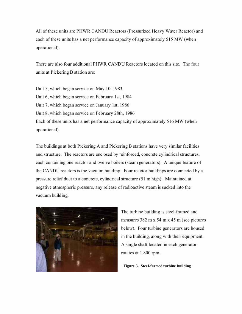
The turbine building is steel-framed and
measures 382 m x 54 m x 45 m (see pictures
below). Four turbine generators are housed
in the building, along with their equipment.
A single shaft located in each generator
rotates at 1,800 rpm.
Figure 3. Steel-framed turbine building

Figure 4. Steel-framed turbine building
Pickering A and B stations send
their heavy water shipments to
Darlington Nuclear Station for
tritium extraction. When fully
operational, Pickering A and B
stations have the total potential of providing 4,120 MW of power (being 23% of
Ontario’s electrical energy supply).
DARLINGTON NUCLEAR GENERATING STATION
Figure 5. Darlington Nuclear Generating Station in the Municipality of Clarington, Ontario Darlington Nuclear Generating Station
is located in the Municipality of
Clarington, in the Province of Ontario
(approximately 70 km east of
Toronto). It is also owned by Ontario
Power Generation and contains four
operational PHWR CANDU reactors.
Unit 1 began service on November 14th, 1992
Unit 2 began service on October 9th, 1990
Unit 3 began service on February 14th, 1993
Unit 4 began service on June 14th, 1993
Each of these units has a net performance capacity of approximately 881 MW (when
operational) and they have a total potential of providing 3,524 MW of power
(approximately 20% of Ontario’s electrical energy supply).

Darlington NGS became the first nuclear station in North America to be certified under
the ISO 14001 environmental standard.
The buildings are similar to that at Pickering NGS. Some differences are:
The vacuum building houses a 71 m high cylindrical concrete structure, which connects
to the reactor buildings. The turbine building is 580 m x 137 m x 45 m and is twelve
stories high. Each of the reactor buildings contain one reactor and four boilers.
Darlington NGS has a tritium removal facility (opened in 1990) which stores the tritium
within a concrete vault in stainless steel containers. This facility serves both Darlington
NGS and Pickering NGS. Ontario Power Generation has received approval from the
Canadian Nuclear Safety Commission to build a dry storage facility at
Darlington NGS. The proposed facility will have the capacity, when fully completed in
2021, to house a total of 1,500 containers (each container having the capacity to hold 384
used fuel bundles).
BRUCE NUCLEAR GENERATING STATION
Figure 6. Bruce Nuclear Generating Station in Tiverton, Ontario Bruce Nuclear Generating
Station is located on Lake
Huron, in Tiverton, Ontario
(approximately 3 hours
north-west of Toronto).
Like Pickering NGS, it also
has two
stations, each containing four PHWR CANDU reactors.
Bruce Station A:
Units 1 and 2 both began service on September 1st, 1977 (non-operational)
Unit 3, began service on February 1st, 1978
Unit 4, began service on January 18th, 1979

Each of these units has a net performance capacity of approximately 750 MW (when
operational).
Bruce Station B:
Unit 5, began service on March 1st, 1985
Unit 6, began service on September 14th, 1984
Unit 7, began service on April 10th, 1986
Unit 8, began service on May 22, 1987
Each of these units has a net performance capacity of approximately 785 MW (when
operational). Bruce Station B units 6 and 7 were among the top 50 performing nuclear
reactors in the world for 2003.
Ontario Hydro originally constructed Bruce NGS in stages from 1970 to 1987. It is
currently owned by Bruce Power Inc. (a partnership among BPC Generation
Infrastructure Trust, Cameco Corporation, TransCanada Corporation, the Power
Workers’ Union and The Society of Energy Professionals). An eighteen-year lease
agreement has been entered into with Ontario Power Generation to take over the
operation of this facility. Bruce NGS has the highest output of electricity in Canada.
POINT LEPREAU NUCLEAR GENERATING STATION
Point Lepreau NGS, with its one nuclear reactor (CANDU-6) is Atlantic Canada’s only
nuclear facility. It is located on the north shore of the Bay of Fundy, in Point Lepreau,
New Brunswick (west of Saint John). Owned by New Brunwick Power Nuclear
Corporation, a Crown Corporation, Point Lepreau NGS was constructed in stages from
1975 to 1983. It began service on February 1st, 1983.
Point Lepreau NGS became the first nuclear facility to be licensed for operation of a
CANDU-6 reactor and to commence its operation. This reactor has a net performance
capacity of approximately 635 MW.

Figure 7. A schematic drawing of a CANDU-6 Reactor plant
GENTILLY 2 NUCLEAR GENERATING STATION
Figure 8. Gentilly 2 Nuclear Generating Station in Becancour, Quebec
The Gentilly 2 NGS is located on the St. Lawrence River, in Becancour, Quebec
(approximately one hour east of Montreal). It is Quebec’s only nuclear facility and is
owned by Hydro-Quebec, a Provincial Crown Corporation. Its close proximity to
Quebec’s main load electrical centers is an important factor in the stabilization of the
province’s grid. Gentilly 2 NGS was constructed in stages from 1966 to 1983 and
contains one reactor, a PHWR CANDU-6. It began service on October 1st, 1983 and has
a net performance capacity of approximately 635 MW.
Canadian Nuclear Association Electronic Newsletter. Volum V, Number 7, dated February 17th, 2004.
Canadian Nuclear Association Electronic Newsletter. Volume V, Number 26, dated August 24th, 2004.

APPENDIX
http://www.candu.org/opg.html
http://www.opg.com/ops/N_pickering.asp
http://www.candu.org/opg.html
http://www.candu.org/opg.html http://www.opg.com/ops/N_darlington.asp
LOCATIONS OFCANADA’S
CANDUREACTORS


