
Sverdrup1
FAILURE MODESAND
EFFECTS ANALYSIS
R. R. MohrJanuary 1994
8th Edition

BACKGROUND…• Premise: You own/operate/require/design/or are responsible for equipmentessential to a system/process/activity which may be small or large, simple orcomplex. It may be a future plan, or be presently in operation.
• Need: Reassurance that causes, effects, and risks of system failures have beenreviewed systematically.
• Approach: Perform an FMEA or FMECA.
FMEA + C = FMECAC = Criticality = Risk = Severity/Probability Assessment
• Analogy: PHL / PHA = FMEA / FMECA
• Classical FMEA Questions (for each system element):
(1) How (i.e., in what ways) can this element fail (failure modes)?(2) What will happen to the system and its environment if this
element does fail in each of the ways available to it (failureeffects)?
• FMEA Origin: FMEA is a tool originated by SAE Reliability Engineers. Itcontinues to be associated by many with Reliability Engineering. It analyzespotential effects caused by system elements ceasing to behave as intended.
2
In casual use,“FMEA” also means
“FMECA” — thedistinction betweenthe two has become
blurred.

DEFINITIONS…• Fault: Inability to function in a desired manner, or operation in an undesired manner,
regardless of cause.
• Failure: A fault owing to breakage, wear out, compromised structural integrity, etc.
FMEA does not limit itself strictly to failures, butincludes faults.
• Failure Mode: The manner in which a fault occurs, i.e. the wayin which the element faults.
• Element Failure Mode ExamplesSwitch open, partially open, closed, partially closed, chatterValve open, partially open, closed, partially closed, wobbleSpring stretch, compress/collapse, fractureCable stretch, break, kink, frayRelay contacts closed, contacts open, coil burnout, coil shortOperator wrong operation to proper item, wrong operation to wrong item
proper operation to wrong item, perform too earlyperform too late, fail to perform
3
“Failure Modes...”is a misnomer — some
sources now call FMEA byanother name:
“Fault Hazard Analysis.”
more ➟
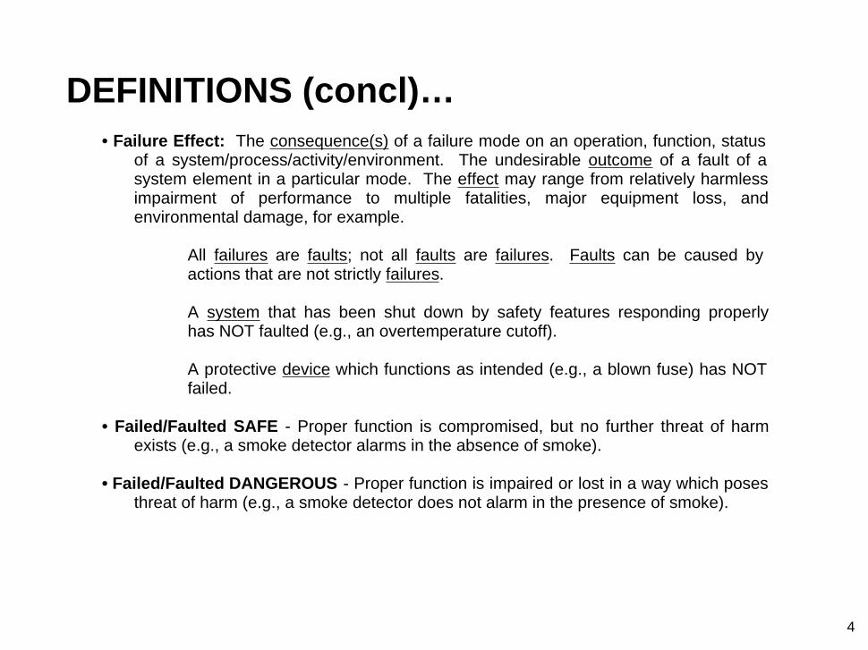
DEFINITIONS (concl)…• Failure Effect: The consequence(s) of a failure mode on an operation, function, status
of a system/process/activity/environment. The undesirable outcome of a fault of asystem element in a particular mode. The effect may range from relatively harmlessimpairment of performance to multiple fatalities, major equipment loss, andenvironmental damage, for example.
All failures are faults; not all faults are failures. Faults can be caused byactions that are not strictly failures.
A system that has been shut down by safety features responding properlyhas NOT faulted (e.g., an overtemperature cutoff).
A protective device which functions as intended (e.g., a blown fuse) has NOTfailed.
• Failed/Faulted SAFE - Proper function is compromised, but no further threat of harmexists (e.g., a smoke detector alarms in the absence of smoke).
• Failed/Faulted DANGEROUS - Proper function is impaired or lost in a way which posesthreat of harm (e.g., a smoke detector does not alarm in the presence of smoke).
4
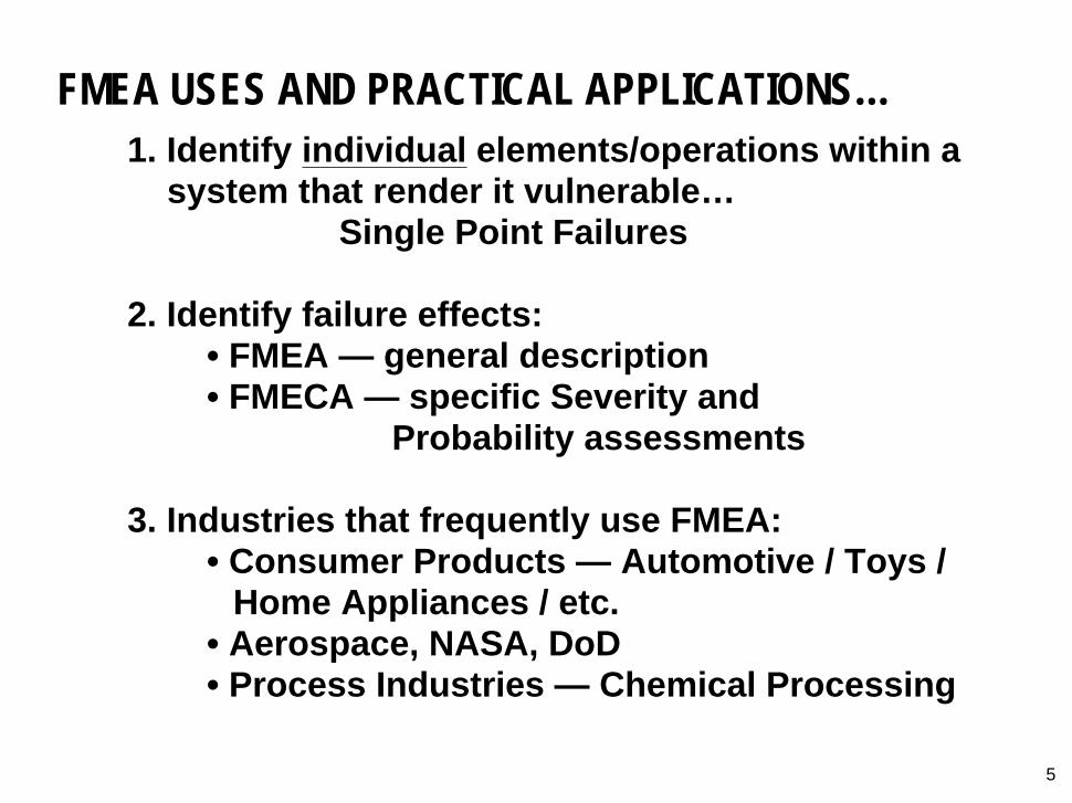
FMEA USES AND PRACTICAL APPLICATIONS…
1. Identify individual elements/operations within asystem that render it vulnerable…
Single Point Failures
2. Identify failure effects:• FMEA — general description• FMECA — specific Severity and
Probability assessments
3. Industries that frequently use FMEA:• Consumer Products — Automotive / Toys /
Home Appliances / etc.• Aerospace, NASA, DoD• Process Industries — Chemical Processing
5

THE PROCESS…1. Define the system to be analyzed, and obtain necessary
drawings, charts, descriptions, diagrams, component lists.Know exactly what you’re analyzing; is it an area, activity,equipment? — all of it, or part of it? What targets are to beconsidered? What mission phases are included?
2. Break the system down into convenient and logical elements.System Breakdown can be either Functional (i.e., according towhat the System Elements “do”), or Geographic/Architectural(i.e., according to where the System Elements “are”), or both(i.e., Functional within the Geographic, or vice versa).
3. Establish a Coding System to identify system elements.
4. Analyze (FMEA) the elements.
6
more ➟
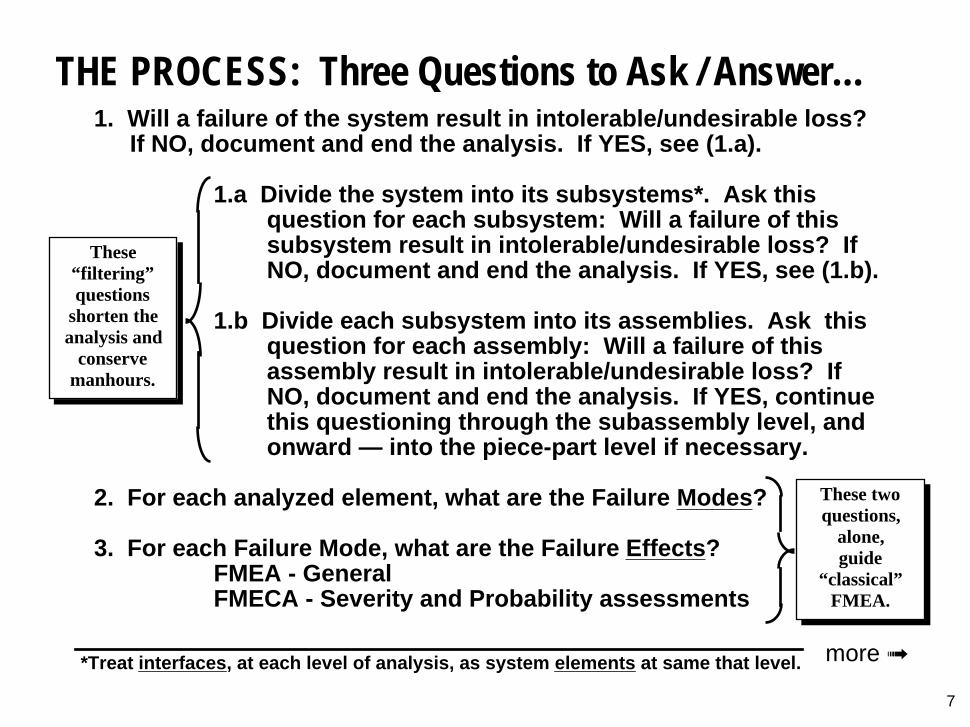
THE PROCESS: Three Questions to Ask / Answer…1. Will a failure of the system result in intolerable/undesirable loss?
If NO, document and end the analysis. If YES, see (1.a).
1.a Divide the system into its subsystems*. Ask thisquestion for each subsystem: Will a failure of thissubsystem result in intolerable/undesirable loss? IfNO, document and end the analysis. If YES, see (1.b).
1.b Divide each subsystem into its assemblies. Ask thisquestion for each assembly: Will a failure of thisassembly result in intolerable/undesirable loss? IfNO, document and end the analysis. If YES, continuethis questioning through the subassembly level, andonward — into the piece-part level if necessary.
2. For each analyzed element, what are the Failure Modes?
3. For each Failure Mode, what are the Failure Effects?FMEA - GeneralFMECA - Severity and Probability assessments
7
These twoquestions,
alone,guide
“classical”FMEA.
These“filtering”questions
shorten theanalysis and
conservemanhours.
*Treat interfaces, at each level of analysis, as system elements at same that level. more ➟
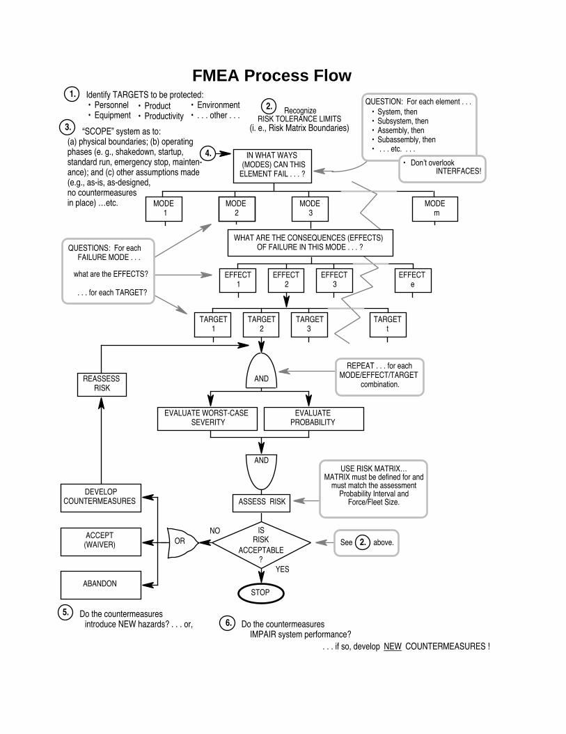
OR
AND
IN WHAT WAYS(MODES) CAN THIS
ELEMENT FAIL . . . ?
FMEA Process Flow
REASSESSRISK
STOP
. . . if so, develop NEW COUNTERMEASURES !
MODEm
AND
ASSESS RISK
ISRISK
ACCEPTABLE?
NO
YES
1. Identify TARGETS to be protected: • Product
• Productivity• Environment• . . . other . . .
• Personnel• Equipment
EFFECT1
EFFECT2
EFFECT3
EFFECTe
MODE3
MODE1
MODE2
QUESTIONS: For each FAILURE MODE . . .
what are the EFFECTS?
. . . for each TARGET?
TARGET1
TARGET2
TARGET3
TARGETt
EVALUATEPROBABILITY
EVALUATE WORST-CASESEVERITY
WHAT ARE THE CONSEQUENCES (EFFECTS)OF FAILURE IN THIS MODE . . . ?
REPEAT . . . for eachMODE/EFFECT/TARGET
combination.
6. Do the countermeasures IMPAIR system performance?
5. Do the countermeasures introduce NEW hazards? . . . or,
DEVELOPCOUNTERMEASURES
ABANDON
ACCEPT(WAIVER)
USE RISK MATRIX…MATRIX must be defined for and
must match the assessmentProbability Interval and
Force/Fleet Size.
• System, then• Subsystem, then• Assembly, then• Subassembly, then• . . . etc. . . .
QUESTION: For each element . . .
• Don’t overlookINTERFACES!
RecognizeRISK TOLERANCE LIMITS
(i. e., Risk Matrix Boundaries)
2.
4.
“SCOPE” system as to:(a) physical boundaries; (b) operatingphases (e. g., shakedown, startup,standard run, emergency stop, mainten-ance); and (c) other assumptions made(e.g., as-is, as-designed,no countermeasuresin place) …etc.
3.
See above.2.
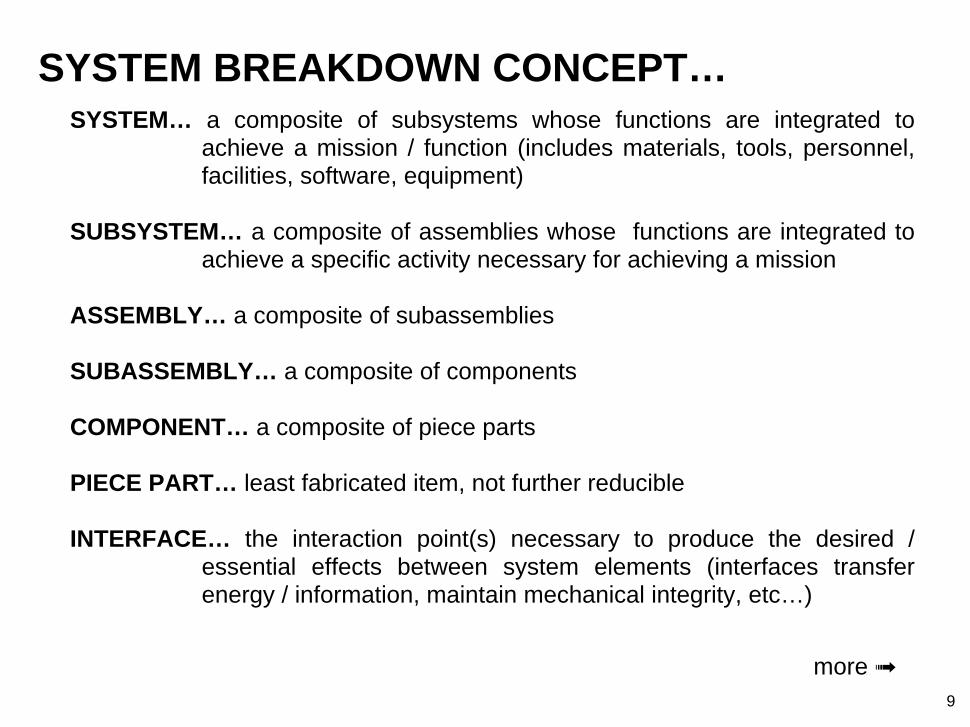
SYSTEM BREAKDOWN CONCEPT…SYSTEM… a composite of subsystems whose functions are integrated to
achieve a mission / function (includes materials, tools, personnel,facilities, software, equipment)
SUBSYSTEM… a composite of assemblies whose functions are integrated toachieve a specific activity necessary for achieving a mission
ASSEMBLY… a composite of subassemblies
SUBASSEMBLY… a composite of components
COMPONENT… a composite of piece parts
PIECE PART… least fabricated item, not further reducible
INTERFACE… the interaction point(s) necessary to produce the desired /essential effects between system elements (interfaces transferenergy / information, maintain mechanical integrity, etc…)
9
more ➟
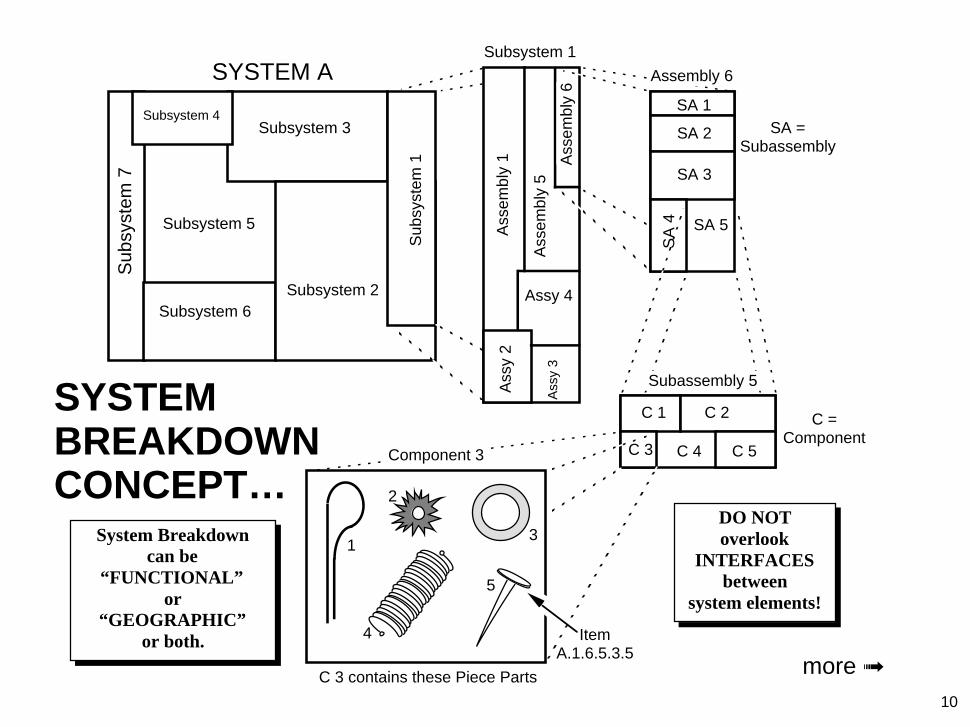
10
System Breakdowncan be
“FUNCTIONAL”or
“GEOGRAPHIC”or both.
SYSTEMBREAKDOWNCONCEPT…
Sub
syst
em 1
Subsystem 2
Subsystem 3
Subsystem 5
Subsystem 6
Sub
syst
em 7
Subsystem 4SA =
Subassembly
C =Component
SYSTEM ASubsystem 1
Ass
embl
y 1
Ass
embl
y 5
Ass
embl
y 6
Ass
y 2
Assy 4
Ass
y 3
SA 1
SA 2
SA 3
SA 5
C 1 C 2
C 3 C 4 C 5
ItemA.1.6.5.3.5
C 3 contains these Piece Parts
Component 3
1
2
3
4
5
Assembly 6
SA
4
Subassembly 5
more ➟
DO NOToverlook
INTERFACESbetween
system elements!

FUNCTIONAL vs. GEOGRAPHICSYSTEM BREAKDOWN…
• Functional:• Cooling System• Propulsion System• Braking System• Steering System• …etc…
• Geographic / Architectural:• Engine Compartment• Passenger Compartment• Dashboard / Control Panel• Rear End• …etc…
11
Don’t neglect interfacecomponents — e.g., if an
engine-driven belt powersboth a water pump and apower steering system, besure to include it as a part
of one, or as a separateInterface Element!
more ➟

SYSTEM BREAKDOWN EXAMPLE…System Subsystem Assembly Subassembly
AUTOMOBILE Cooling radiatorwater pumpcoolanthoses/clampsengine blockthermostat
Propulsion fuel storagedeliverycarburetor
air carburetorspark/ignition battery
generatorplugscoildistributor
engine headsblockpistonsvalves
transmission (more…)Braking standard (more…)
emergency (more…)Chassis/Body engine comp.
passenger comp.storage comp.front bumperrear bumperfendersgages & indicators
Steering (more…)Electrical (more…)Suspension (more…)Operator (more…)
12
Some breakdownscombine Functional andGeographic approaches.This can help to ensure
thoroughness.
more ➟

NUMERICAL CODING SYSTEM…
13
SYSTEM: AUTOMOBILE
SUBSYSTEMS
ASSEMBLIES
COOLING - 10 PROPULSION - 20 BRAKING - 30 STEERING - 40
Radiator10-11
Water Pump10-12
Coolant10-13
Hoses/Clamps10-14
Engine Block10-15
Thermostat10-16
Subassemblies Radiator Body10-11-01
Radiator Cap10-11-02
Develop/implement aCoding System thatgives each analyzed
system element aunique identification.
more ➟

DON’T OVERLOOK THESE…
14
• Utilities — electricity, compressed air, coolingwater, pressurized lube oil, steam, etc.
• Human support activities — e.g., processcontrol,
• Interface Elements
• All applicable mission phases (for any potentialtarget)
• Passive elements in non-hostile environments— e.g., electrical wires
• Static or non-loaded elements — e.g.,decorative trim
ELEMENTS CONVENTIONALLY IGNORED…

TYPICAL FMEA WORKSHEET INFORMATION…
1. General administrative / heading information
2. Identification number (from System Breakdown)
3. Item name
4. Operational Phase(s)
5. Failure mode
6. Failure cause
7. Failure effect
8. Target(s)
9. Risk assessment (Severity / Probability / Risk)
10. Action required / remarks
15
more ➟

16
FMEA/Worksheet
Sheet 11 of 44 Date: 6 Feb '92 Prep. by: R. R. Mohr Rev. by: S. Perleman Approved by: G. Roper
FMEA No.: N/246.n Project No.: Osh-004-92 Subsystem: Illumination System: Headlamp Cntrls Probability Interval: 20 years
SEV PROB
Sverdrup Technology, Inc.Failure Modes & Effects Analysis
IDENT.No.
ITEM/FUNCTIONAL
IDENT.
FAILUREMODE
FAILURECAUSE
FAILUREEFFECT
RISKASSESSMENT
ACTION REQUIRED / REMARKS
TARGET
RiskCode
P: Personnel / E: Equipment / T: Downtime / M: Mission / V: Environment
R/N.42 Relay K-28/Contacts(Normally Open)
Open w/Command to Close
Corrosion/orMfg. Defect/or BasicCoil Failure (Open)
Loss of forwardillumination/Impair-ment of night vision/Potential collision(s) w/unillumi-nated obstacles
Redesign headlamp circuit to produce headlamp fail-on, w/timed off feature to protect battery, or eliminate relay/use HD Sw. at panel.
P I D 2E III D 3T I D 2 M I D 2
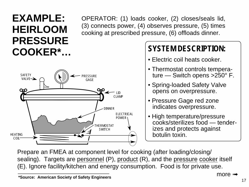
EXAMPLE:HEIRLOOMPRESSURECOOKER*…
17
SYSTEM DESCRIPTION:• Electric coil heats cooker.
• Thermostat controls tempera-ture — Switch opens >250° F.
• Spring-loaded Safety Valveopens on overpressure.
• Pressure Gage red zoneindicates overpressure.
• High temperature/pressurecooks/sterilizes food — tender-izes and protects againstbotulin toxin.
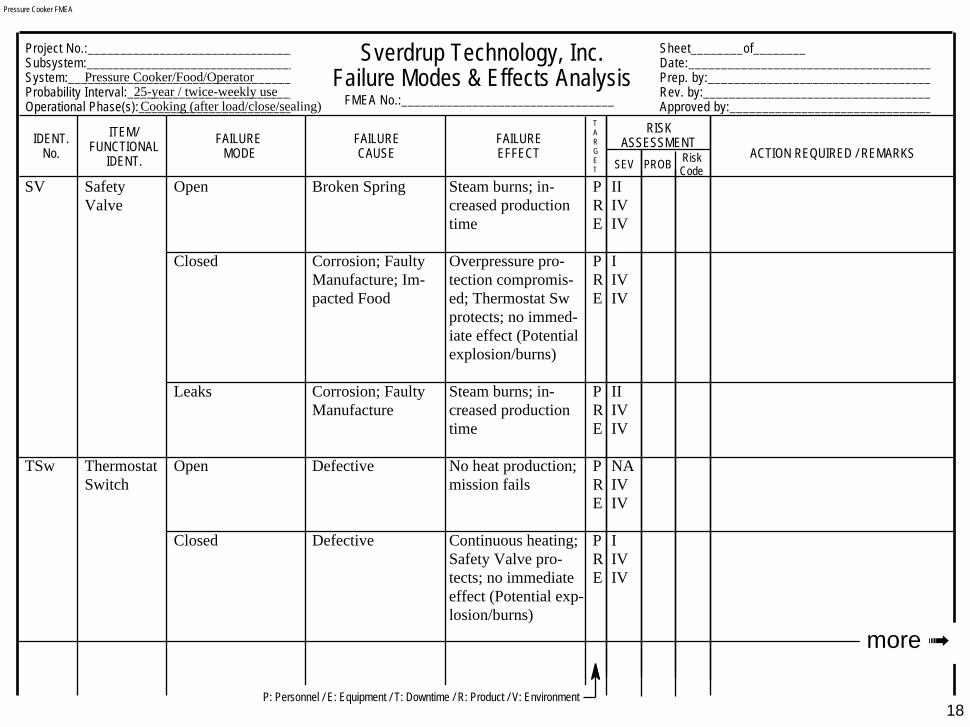
Prepare an FMEA at component level for cooking (after loading/closing/sealing). Targets are personnel (P), product (R), and the pressure cooker itself(E). Ignore facility/kitchen and energy consumption. Food is for private use.
*Source: American Society of Safety Engineers more ➟
PRESSUREGAGE
LIDCLAMP
HEATINGCOIL
SAFETYVALVE
ELECTRICALPOWER
DINNER
THERMOSTATSWITCH
OPERATOR: (1) loads cooker, (2) closes/seals lid,(3) connects power, (4) observes pressure, (5) timescooking at prescribed pressure, (6) offloads dinner.
Sheet________of________Date:_____________________________________Prep. by:__________________________________Rev. by:___________________________________Approved by:_______________________________
Project No.:________________________________Subsystem:________________________________System:___________________________________Probability Interval:__________________________Operational Phase(s):_________________________
SEV PROB
Sverdrup Technology, Inc.Failure Modes & Effects Analysis
IDENT.No.
ITEM/FUNCTIONAL
IDENT.
FAILUREMODE
FAILURECAUSE
FAILUREEFFECT
RISKASSESSMENT
ACTION REQUIRED / REMARKS
TARGET
RiskCode
FMEA No.:_________________________________
18
Pressure Cooker FMEA
SV Safety Open Broken Spring Steam burns; in- P IIValve creased production R IV
time E IV
Closed Corrosion; Faulty Overpressure pro- P IManufacture; Im- tection compromis- R IVpacted Food ed; Thermostat Sw E IV
protects; no immed-iate effect (Potentialexplosion/burns)
Leaks Corrosion; Faulty Steam burns; in- P IIManufacture creased production R IV
time E IV
TSw Thermostat Open Defective No heat production; P NASwitch mission fails R IV
E IV
Closed Defective Continuous heating; P ISafety Valve pro- R IVtects; no immediate E IVeffect (Potential exp-losion/burns)
25-year / twice-weekly usePressure Cooker/Food/Operator
more ➟
Cooking (after load/close/sealing)
P: Personnel / E: Equipment / T: Downtime / R: Product / V: Environment

SEV PROB
IDENT.No.
ITEM/FUNCTIONAL
IDENT.
FAILUREMODE
FAILURECAUSE
FAILUREEFFECT
RISKASSESSMENT
ACTION REQUIRED / REMARKS
TARGET
RiskCode
P: Personnel / E: Equipment / T: Downtime / R: Product / V: Environment
Pressure Cooker FMEA (cont)
19
PG Pressure False High Reading Defective; Stuck Dinner undercooked; P IGage bacteria/toxins not R IV
destroyed; OR… E IV
Operator intervenes/ P NAinterrupts process R IV(mission fails) E IV
False Low Reading Defective; Stuck Dinner overcooked; P ISafety Valve pro- R IVtects/releases steam E IVif Thermostat Swfails closed (Potent-ial explosion/burns)
CLMP Lid Fracture/Thread Defective Explosive pressure P IClamp(s) Strip release; flying R IV
debris/burns E IV
more ➟

Pressure Cooker FMEA (conc)
20
SEV PROB
IDENT.No.
ITEM/FUNCTIONAL
IDENT.
FAILUREMODE
FAILURECAUSE
FAILUREEFFECT
RISKASSESSMENT
ACTION REQUIRED / REMARKS
TARGET
RiskCode
P: Personnel / E: Equipment / T: Downtime / R: Product / V: Environment

21
ZOOLOGICALFMEA…
more ➟
Not toScale
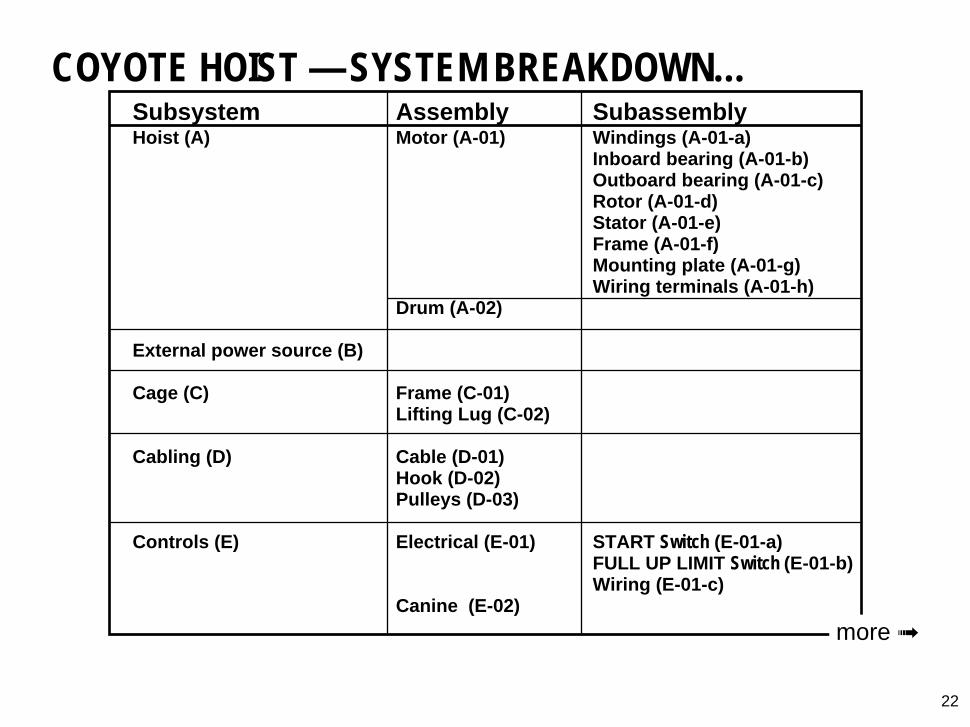
COYOTE HOIST — SYSTEM BREAKDOWN…Subsystem Assembly SubassemblyHoist (A) Motor (A-01) Windings (A-01-a)
Inboard bearing (A-01-b)Outboard bearing (A-01-c)Rotor (A-01-d)Stator (A-01-e)Frame (A-01-f)Mounting plate (A-01-g)Wiring terminals (A-01-h)
Drum (A-02)
External power source (B)
Cage (C) Frame (C-01)Lifting Lug (C-02)
Cabling (D) Cable (D-01)Hook (D-02)Pulleys (D-03)
Controls (E) Electrical (E-01) START Switch (E-01-a)FULL UP LIMIT Switch (E-01-b)Wiring (E-01-c)
Canine (E-02)
22
more ➟
Sheet________of________Date:_____________________________________Prep. by:__________________________________Rev. by:___________________________________Approved by:_______________________________
Project No.:________________________________Subsystem:________________________________System:___________________________________Probability Interval:__________________________Operational Phase(s):_________________________
SEV PROB
Sverdrup Technology, Inc.Failure Modes & Effects Analysis
IDENT.No.
ITEM/FUNCTIONAL
IDENT.
FAILUREMODE
FAILURECAUSE
FAILUREEFFECT
RISKASSESSMENT
ACTION REQUIRED / REMARKS
TARGET
RiskCode
FMEA No.:_________________________________
P: Personnel / E: Equipment / T: Downtime / R: Product / V: Environment
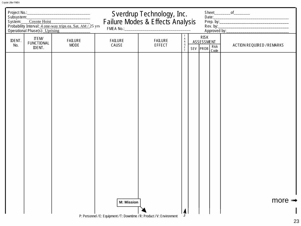
Coyote Lifter FMEA
23
Coyote Hoist4 one-way trips ea. Sat. AM / 25 yrs
Uprising
more ➟M: Mission
24
Coyote Lifter FMEA (conc)
SEV PROB
IDENT.No.
ITEM/FUNCTIONAL
IDENT.
FAILUREMODE
FAILURECAUSE
FAILUREEFFECT
RISKASSESSMENT
ACTION REQUIRED / REMARKS
TARGET
RiskCode
P: Personnel / E: Equipment / T: Downtime / R: Product / V: Environment
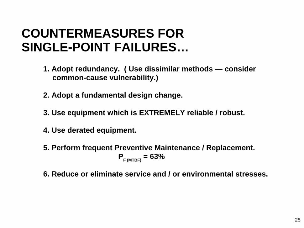
COUNTERMEASURES FORSINGLE-POINT FAILURES…
1. Adopt redundancy. ( Use dissimilar methods — considercommon-cause vulnerability.)
2. Adopt a fundamental design change.
3. Use equipment which is EXTREMELY reliable / robust.
4. Use derated equipment.
5. Perform frequent Preventive Maintenance / Replacement.P
F (MTBF) = 63%
6. Reduce or eliminate service and / or environmental stresses.
25
WHEN IS AN FMEA BEST PERFORMED…?
• An FMEA cannot be done until design hasproceeded to the point that System Elementshave been selected at the level the analysis is toexplore.
• Ideally, FMEA is best done in conjunction with orsoon after PHA efforts. Results can be used toidentify high-vulnerability elements and to guideresource deployment for best benefit. An FMEAcan be done anytime in the system lifetime,from initial design onward.
26

PRINCIPAL LIMITATIONS & ABUSES OF FMEA…• Frequently, human errors and hostile environments are
overlooked.
• Because the technique examines individual faults of systemelements taken singly, the combined effects of coexistingfailures are not considered.
• If the system is at all complex and if the analysis extends to theassembly level or lower, the process can be extraordinarilytedious and time consuming.
• Failure probabilities can be hard to obtain; obtaining,interpreting, and applying those data to unique or high-stresssystems introduces uncertainty which itself may be hard toevaluate.
• Sometimes FMEA is done only to satisfy the altruistic urge orneed to “do safety.” Remember that the FMEA will find andsummarize system vulnerability to SPFs, and it will require lotsof time, money, and effort. How does the recipient intend touse the results? Why does he need the analysis?
27
more ➟
FMEA LIMITATIONS & ABUSES (cont)…
• Ignoring the role of Mission Phasing.
• When a facility proprietor learns the facility has 100s or 1000s ofSPFs, frequently he panics, develops SPF paranoia, anddemands “Critical Items Lists” or “Total SystemRedundification.” This paranoia leads to (1) misplaced fear(“This SPF-loaded system is sure to get us one day!”) and (2)loss of focus on other, possibly deadlier, system threats.
28
more ➟

FMEA LIMITATIONS & ABUSES (cont)…
Each day you… (a biological bundle of SPFs with only 1brain,spinal chord, stomach, bladder, liver,pancreas)
drive your vehicle… (a rolling cathedral of SPFs with only 1 engine,brake pedal, carburetor, steering wheel,radio, fuel gage)
to work … (past a jungle of SPFs — traffic signals, othervehicles, bridges)
to spend the day… (at a facility laden with SPFs — 1 desk,computer, wastebasket)
earning moneyto buy commodities… (filled with SPFs — TV with 1 picture tube,
toaster with 1 cord, phone with 1 of eachpushbutton)
29
Single Points Abound! You encounter them daily, yet continue tofunction. Remember:
more ➟Most system nastiness results from complexthreats, not from SPFs — don’t ignoreSPFs, just keep them in perspective.

FMEA LIMITATIONS & ABUSES (concl)…
Redundifying to reduce the single-point threat?Will the amount spent on redundifying exceed the price you
would pay if the undesired event occurred? Don’t forget to
include the cost of redundant parts, their installation, and their
upkeep. Don’t overlook the need to make room and weight
allowances for the extra equipment. How are you going to
protect yourself against common-causing? Who decides which
of two identical items is the “routine-use item” and which is the
“backup?” You’ll have to devise means for switching from to the
other. If it’s an automatic switching device, don’t forget to
redundify that element, too!
30
BENEFITS OF FMEA…• Discovers potential single-point failures.
• Assesses risk (FMECA) for potential, single-element failures foreach identified target, within each mission phase.
• Knowing these things helps to:- optimize reliability, hence mission accomplishment.- guide design evaluation and improvement.- guide design of system to “fail safe” or crash softly.- guide design of system to operate satisfactorily
using equipment of “low” reliability.- guide component/manufacturer selection.
• High-risk hazards found in a PHA can be analyzed to thepiece-part level using FMEA.
• Hazards caused by failures identified in the FMEA can be addedto the PHA, if they haven’t already been logged there.
• FMEA complements Fault Tree Analysis and other techniques.
31

BIBLIOGRAPHY…• Procedures for Performing a Failure Mode, Effects and
Criticality Analysis MIL-STD-1629A, Nov. 1980.
• System Safety Engineering And Management Harold E.Roland & Brian Moriarty. John Wiley & Sons; 2nd Edition;1990. (See Ch. 28, “Failure Mode and Effect Analysis.”)
• Assurance Technologies - Principles and Practices Dev G.Raheja. McGraw-Hill, Inc.: 1991.
• Fault Tree Handbook N. H. Roberts, W. E. Vesely, D. F. Haasl,F. F. Goldberg. NUREG-0492. U.S. Government PrintingOffice, Washington, DC: 1981. (See Ch. II, “Overview ofInductive Methods.”)
• Systems Safety - Including DOD Standards Donald Layton.Weber Systems Inc., Chesterland, OH: 1989. (See Ch. 7,“Hazard Analysis Techniques I.”)
• Loss Prevention in the Process Industries (2 vols.) Frank P.Lees. Butterworths, London: 1980. (See Vol. 1, Ch. 7,“Reliability Engineering.”)
32

THE FMEAREPORT…
33
EXECUTIVE SUMMARY [Abstract of complete report] SCOPE OF THE ANALYSIS…
Brief System DescriptionAnalysis Boundaries
Physical Boundaries Operational BoundariesOperational Phases Targets Recognized/IgnoredHuman Operator in/out Exposure IntervalInterfaces Treated Others…
THE ANALYSIS…Discuss FMEA Method — Strengths/Limitations [Cite Refs.]Present Risk Assessment Matrix [if used]State Resolution Level(s) used/how decidedDescribe Software Used [If applicable]Present/Discuss the Analysis Data ResultsDiscuss Trade Studies [If done]
FINDINGS…Interpretation of Analysis ResultsPredominant Hazards [Overall “Census” and comments on “Repeaters”]Comments on High Risk Hazards [High from Severity or Probability?
Countermeasures Effective?]Comments on High Severity Risks [Probability acceptably low?]Chief Contributors to Overall System Risk
CONCLUSIONS AND RECOMMENDATIONS …[Interpret Findings — Is overall Risk under acceptable control? — Is furtheranalysis needed? …by what method(s)?]
ANALYSIS WORKSHEETS…[Present as Table or Appendix — use Indenture Coding as an introductory Tableof Contents]
Show Worksheets asan Appendix orattached Table.
Say what is analyzedand
what is not analyzed.
F M E AF M E ASystemAuthor
CompanyDate
…etc…
APPENDIX
Example FMEA Worksheets
34APPENDIX
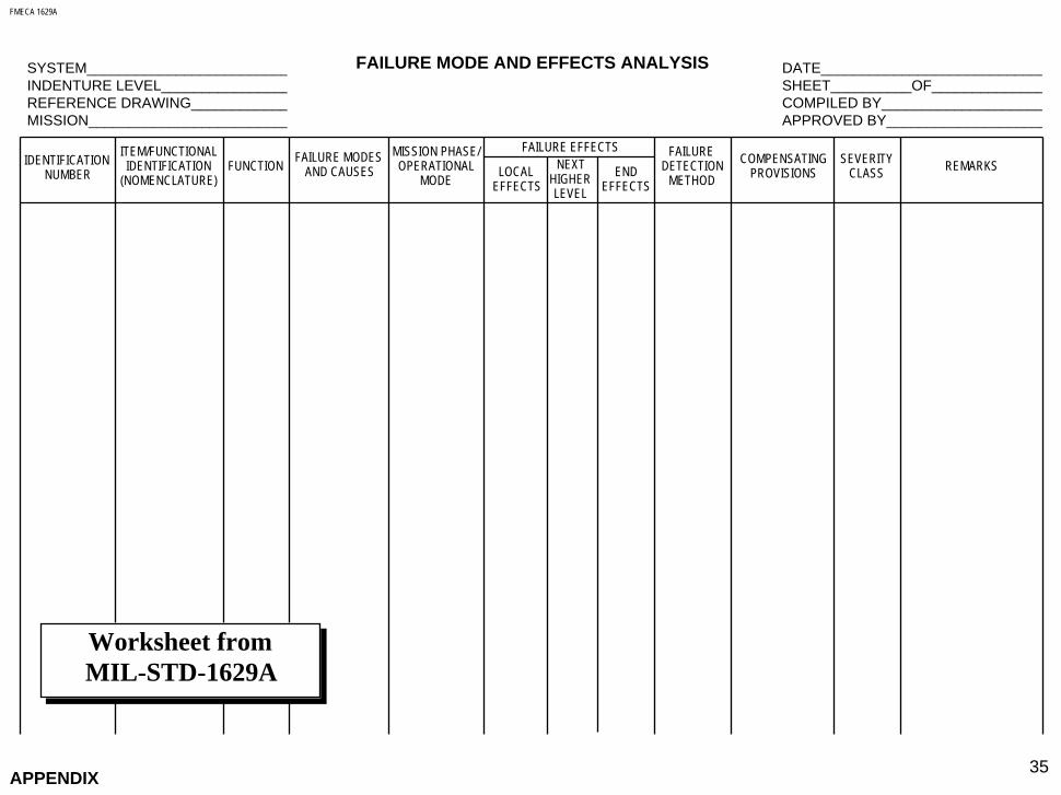
FMECA 1629A
35APPENDIX
FAILURE MODE AND EFFECTS ANALYSIS
IDENTIFICATIONNUMBER
ITEM/FUNCTIONALIDENTIFICATION
(NOMENCLATURE)FUNCTION
FAILURE MODESAND CAUSES
MISSION PHASE/OPERATIONAL
MODE
FAILURE EFFECTS
LOCALEFFECTS
NEXTHIGHERLEVEL
ENDEFFECTS
FAILUREDETECTION
METHOD
COMPENSATINGPROVISIONS
SEVERITYCLASS
REMARKS
SYSTEM__________________________INDENTURE LEVEL_________________REFERENCE DRAWING_____________MISSION__________________________
DATE_____________________________SHEET__________OF_______________COMPILED BY_____________________APPROVED BY____________________
Worksheet fromMIL-STD-1629A

CRITICALITY ANALYSIS 1629A
36APPENDIX
CRITICALITY ANALYSIS
IDENTIFICATIONNUMBER
ITEM/FUNCTIONALIDENTIFICATION
(NOMENCLATURE)
FUNCTION FAILURE MODESAND
CAUSES
MISSION PHASE/OPERATIONAL
MODE
SEVERITYCLASS
REMARKS
SYSTEM__________________________INDENTURE LEVEL_________________REFERENCE DRAWING_____________MISSION__________________________
DATE_____________________________SHEET__________OF_______________COMPILED BY_____________________APPROVED BY____________________
FAILUREPROBABILITY
FAILURE RATEDATA SOURCE
FAILUREEFFECT
PROBABILITY
(β)
FAILUREMODERATIO
(α)
FAILURERATE
(λp)
OPERATINGTIME
(t)
FAILUREMODECRIT #
Cm=βαλ
pt
ITEMCRIT #
Cr=Σ(C
m)
Worksheet fromMIL-STD-1629A
Sverdrup FMEA
37APPENDIX
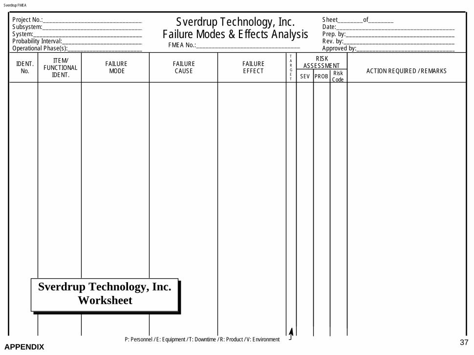
Sheet________of________Date:_____________________________________Prep. by:__________________________________Rev. by:___________________________________Approved by:_______________________________
Project No.:________________________________Subsystem:________________________________System:___________________________________Probability Interval:__________________________Operational Phase(s):_________________________
SEV PROB
Sverdrup Technology, Inc.Failure Modes & Effects Analysis
IDENT.No.
ITEM/FUNCTIONAL
IDENT.
FAILUREMODE
FAILURECAUSE
FAILUREEFFECT
RISKASSESSMENT
ACTION REQUIRED / REMARKS
TARGET
RiskCode
FMEA No.:_________________________________
P: Personnel / E: Equipment / T: Downtime / R: Product / V: Environment
Sverdrup Technology, Inc.Worksheet
TOPICS COVERED…
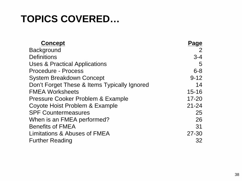
Concept PageBackground 2Definitions 3-4Uses & Practical Applications 5Procedure - Process 6-8System Breakdown Concept 9-12Don’t Forget These & Items Typically Ignored 14FMEA Worksheets 15-16Pressure Cooker Problem & Example 17-20Coyote Hoist Problem & Example 21-24SPF Countermeasures 25When is an FMEA performed? 26Benefits of FMEA 31Limitations & Abuses of FMEA 27-30Further Reading 32
38


