
Ferromagnetic Resonance Spin Pumping and Electrical Spin Injection in Silicon-BasedMetal-Oxide-Semiconductor Heterostructures
Y. Pu,1,* P. M. Odenthal,2 R. Adur,1 J. Beardsley,1 A. G. Swartz,2 D. V. Pelekhov,1 M. E. Flatté,3
R. K. Kawakami,1,2 J. Pelz,1 P. C. Hammel,1 and E. Johnston-Halperin1,†1Department of Physics, The Ohio State University, Columbus, Ohio 43210, USA
2Department of Physics and Astronomy, University of California, Riverside, California 92521, USA3Departent of Physics and Astronomy, University of Iowa, Iowa City, Iowa 52242, USA
(Received 15 January 2015; published 10 December 2015)
We present the measurement of ferromagnetic resonance (FMR-)driven spin pumping and three-terminalelectrical spin injection within the same silicon-based device. Both effects manifest in a dc spinaccumulation voltage Vs that is suppressed as an applied field is rotated to the out-of-plane direction,i.e., the oblique Hanle geometry. Comparison of Vs between these two spin injection mechanisms revealsan anomalously strong suppression of FMR-driven spin pumping with increasing out-of-plane field Hz
app.We propose that the presence of the large ac component to the spin current generated by the spin pumpingapproach, expected to exceed the dc value by 2 orders of magnitude, is the origin of this discrepancythrough its influence on the spin dynamics at the oxide-silicon interface. This convolution, wherein thedynamics of both the injector and the interface play a significant role in the spin accumulation, represents anew regime for spin injection that is not well described by existing models of either FMR-driven spinpumping or electrical spin injection.
DOI: 10.1103/PhysRevLett.115.246602 PACS numbers: 72.25.Dc, 72.25.Hg, 75.76.+j, 76.50.+g
Injecting and coherently controlling spin currents innonmagnetic (NM) channels is a central goal of modernsemiconductor spintronics [1–10]. Ferromagnetic resonance(FMR-)driven spin pumping [11–23] is an emerging methodto dynamically inject pure spin current into a NM with noneed for an accompanying charge current, promising sub-stantial impacts on low energy cost or high efficiencyelectronics [1,2,11–13]. In contrast to conventional spininjection techniques that introduce a constant (dc) polariza-tion component parallel to the magnetization of the ferro-magnet (FM), FMR-driven spin pumping also injects arotating (ac) component that is typically orders of magnitudelarger than the dc component and oriented perpendicular tothe equilibrium magnetization [11,23]. The presence ofthis large ac component renders the simple model of theFMR-pumped spin current as a traditional electrically drivendc spin current in the absence of charge incomplete. Thissituation is further complicated by the fact that while the bulkof experimental work on electrically driven spin injectionrelies on the measurement of a spin accumulation via thechange in chemical potential at a magnetic detector [1–7],FMR-driven spin pumping studies have, to date, reliedalmost exclusively on measuring spin currents via a trans-verse voltage generated by the inverse spin-Hall effect(ISHE) [11–20]. As a result, there is to date no directexperimental comparison between these two regimes and nouniversal framework for understanding spin injection in bothstatic (dc) and dynamic (ac) modalities.Here we report measurements of both electrical spin
injection and FMR-driven spin pumping in the same
Si-based metal-oxide-semiconductor heterostructurethrough measurements of the spin accumulation voltageVs. Comparison of Vs between these two spin injectionmechanisms reveals an anomalously strong suppression ofFMR-driven spin pumping with increasing out-of-planefield Hz
app that cannot be explained within existingmodels for dc spin injection. We propose that the largeac component of the spin current in the spin pumpingapproach is the source of this discrepancy, which arisesfrom the interplay between this ac spin current andthe inherent dynamics of the spin accumulation itself.These results lay the foundation for a universal modelof spin injection and demonstrate the role of ac spininjection in determining the dynamics of the injected spinensemble.In our experiments, tunnel diodes are fabricated from
Feð10 nmÞ=MgOð1.3 nmÞ=Sið100Þ heterostructures grownby molecular beam epitaxy. The p-type Si substrates aresemiconductor-on-insulator wafers with a 3 μm thick Sidevice layer containing 5 × 1018 cm−3 boron dopants, pro-ducing a room temperature resistivity of 2 × 10⁻² Ωcm. Thedevice is patterned by conventional photolithography tech-niques into a Fe=MgO=Si tunnel contact of 500 × 500 μm2
lateral size, placed 1mm away fromAu reference contacts forvoltage measurements. For both traditional three-terminalelectrical spin injection and FMR-driven spin pumpingmeasurements the samples are placed in the resonant cavityof a Bruker electron paramagnetic resonance spectrometerwith resonant frequency f ¼ 9.85 GHz and a dc magneticfield Happ applied along the x axis, as sketched in Fig. 1(a).
PRL 115, 246602 (2015) P HY S I CA L R EV I EW LE T T ER Sweek ending
11 DECEMBER 2015
0031-9007=15=115(24)=246602(6) 246602-1 © 2015 American Physical Society

For three-terminal measurements the current drive isturned on and the microwave field is turned off, while forFMR-driven spin pumping the current drive is turned offand the microwave field is turned on. This arrangementallows for the measurement of electrical and FMR-drivenspin injection in the same device with identical contactgeometry, interface electronic structure, and dc magneticfield geometry. In both cases, the resulting spin currentinduces an imbalance in the spin-resolved electrochemicalpotential and consequent spin accumulation given byΔμS ¼ μ↑ − μ↓, where μ↑ and μ↓ are the chemical poten-tials of up and down spins, respectively. Using standardelectrical spin detection techniques [4–6,24–29] the spinaccumulation can be detected electrically by measuring thespin-resolved voltage Vs between Fe and Si:
VS ¼P2e
ΔμS; ð1Þ
where P is the spin polarization of Fe and ΔμS is assumedto be proportional to the component of the net spinpolarization parallel to the magnetization, M. Figure 1(b)shows the results of a traditional three-terminal Hanlemeasurement, with the expected suppression of spinpolarization with increasing field [4–6,24–29].Consistent with previous reports from our group and others[24–29], we extract an effective spin lifetime of 110 ps, andsystematic studies reveal both the so-called inverted Hanleeffect and current-voltage characteristics consistent withthe presence of interface states mediating the spin transportbetween the Fe=MgO electrode and the Si channel (seeSupplemental Material [30]). This suggests that the spinaccumulation signal is dominated by the interface, ratherthan the bulk Si channel, which is consistent with previousreports [27–29]. Figure 1(c) shows both the inductivelydetected FMR signal from the Fe electrode (upper panel) andthe response of Vs over the same field range (lower panel) inthe presence of microwave excitation of 200 mW (the powerused for all subsequent spin pumping measurements) andwith no dc applied current and the sample placed in thecenter of a rectangular cavity (TE 102 mode). The spinaccumulation voltage shows a clear response coincident withFe FMR signal (with both symmetric and antisymmetricLorentzian components) and an amplitude of roughly 2 μV.However, as has been established in earlier work involvingISHE detection of spin pumping [12–22], the presence of themicrowave field has the potential to introduce a number ofmagnetoresistive and spin-thermal artifacts. We thereforeturn our attention to a series of control measurements tofurther elucidate the origin of this signal.Figure 1(d) shows the rf power Prf dependence of the
FMR intensity (upper panel) and Vs (lower panel) onresonance; the former is proportional to the square root ofPrf and the latter is linear with Prf over the range 0–200 mW,consistent with ISHE detected spin pumping [18–20].Further, as shown in Fig. 1(e), Vs is constant when Mreverses, consistent with our local detection geometrywherein the injected spin is always parallel to the magneti-zation of the FM electrode and inconsistent with theresponse expected from ISHE generated voltages [18–20].Measurement between two Au reference contacts [Fig. 1(e),open circles] further confirms that the signal is not fromspurious microwave-induced voltages. A comprehensiveanalysis of other previously observed magnetotransportartifacts (see Supplemental Material [30]) yields similarresults; i.e., the characteristics of these artifacts eitherqualitatively disagree with the symmetry of our observedsignal or are quantitatively negligible for our specificmeasurement.While the results of these control measurements are a
strong indication that the response in Vs does in fact arisefrom FMR-driven spin pumping, the widely accepted goldstandard for demonstrating the presence of a nonequili-brium spin accumulation is the presence of ensemble
FIG. 1 (color online). (a) Schematic of experimental setup andband diagram of electrical injection (left-hand panel) and FMR-driven spin pumping (right-hand panel). (b) Hanle effect of dc(electrical) spin injection with 0.1 mA dc current applied.(c) FMR intensity (upper panel; arrows indicate state of the Femagnetization) and spin-resolved voltage Vs (lower panel) as afunction of applied magnetic field along the x axis. (d) FMRintensity (upper panel) and spin-resolved voltage (lower panel) asa function of rf power. (e) Solid symbols: Vs vsHapp whenHapp isparallel or antiparallel with the x axis; open symbols indicate thevoltage between two Au=Si reference contacts. All data aremeasured under the same experimental conditions.
PRL 115, 246602 (2015) P HY S I CA L R EV I EW LE T T ER Sweek ending
11 DECEMBER 2015
246602-2
dephasing induced by a transverse dc magnetic field (theHanle effect [1,4–6]). In the traditional Hanle geometryused to obtain the data shown in Fig. 1(b), the in-plane dcfield (Hx
app) is set to zero while the out-of-plane component(Hz
app) is systematically varied. However, measurements ofFMR-driven spin pumping present an additional constraint:while increasing the out-of-plane component of the dcmagnetic field (Hz
app) the in-plane component (Hxapp) must
be finite and tuned the resonant field for FMR in theelectrode. The resulting vector magnetic field varies in bothmagnitude and angle with respect to the sample plane,resulting in a slightly modified version known as theoblique Hanle geometry [24,28] [Fig. 2(a), inset].Because of the strong demagnetization field of our thin-
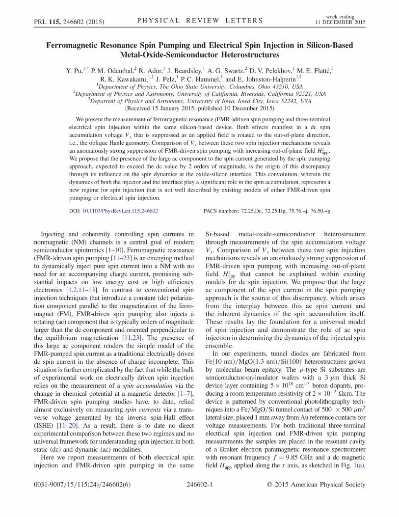
film geometry (∼2.2 T), the orientation of the magnetiza-tion lags the orientation of the applied field, remainingalmost entirely in plane (the maximum estimated deviationis 2°). Since the injected spins (both ac and dc terms) shouldfollow the corresponding component of M, the relativeangle between the spin ensemble and the magnetizationshould not change with the tilt of M, leading to a constantintensity of the FMR response. Figure 2(a) shows the FMRspectrum for different angles Φ; the resonant field HFMRchanges from 250 to 400 G as Φ changes from 0 to 40 deg.This increase is consistent with the fact that the in-planecomponent of H primarily determines the resonance con-dition; so as Φ increases, a larger total applied field istherefore required to achieve resonance (see SupplementalMaterial [30]). Figure 2(b) shows Vs vs Happ over the sameangular range. The peak position of Vs shifts in parallelwith the FMR spectrum, but the peak value decreases withincreasing Hz and vanishes at an angle of approximately40 deg. Note that this suppression of Vs further rules outboth magnetoresistive and spin-thermal artifacts as both themicrowave environment and the FMR in the Fe electrodeare effectively unchanged by this rotation of the magneticfield. We repeat this oblique Hanle measurement for theelectrical injection geometry, with the total applied field ata given angle selected for consistency with the shifting ofthe FMR resonance. The full data set can be found in the
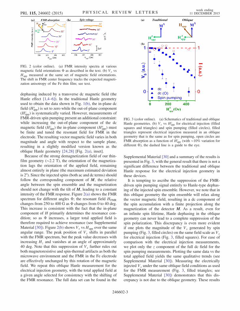
Supplemental Material [30] and a summary of the results ispresented in Fig. 3, with the general result that there is not asignificant difference between the traditional and obliqueHanle response for the electrical injection geometry inthese devices.It is tempting to ascribe the suppression of the FMR-
driven spin pumping signal entirely to Hanle-type dephas-ing of the injected spin ensemble. However, we note that inthis oblique geometry the spin ensemble will relax alongthe vector magnetic field, resulting in a dc component ofthe spin accumulation with a finite projection along themagnetization of the detector M. As a result, even foran infinite spin lifetime, Hanle dephasing in the obliquegeometry can never lead to a complete suppression of thespin polarization. This discrepancy is even more evidentif one plots the magnitude of the Vs generated by spinpumping (Fig. 3, filled circles) on the same field scale as Vsfor electrical injection (Fig. 3, filled squares). For ease ofcomparison with the electrical injection measurements,we plot only the z component of the full dc field for thespin pumping measurements. Plotting the same data vs thetotal applied field yields the same qualitative trends (seeSupplemental Material [30]). Measuring the electricallyinjected Vs under the same oblique field conditions as usedfor the FMR measurement (Fig. 3, filled triangles; seeSupplemental Material [30]) demonstrates that this dis-crepancy is not due to the oblique geometry. These results
FIG. 2 (color online). (a) FMR intensity spectra at variousmagnetic field orientations Φ as described in the text. (b) Vs vsHapp measured at the same set of magnetic field orientations.The shift in FMR center frequency tracks the expected magneti-zation anisotropy of the Fe thin film; see text.
FIG. 3 (color online). (a) Schematics of traditional and obliqueHanle geometries. (b) Vs vs Hz
app for electrical injection (filledsquares and triangles) and spin pumping (filled circles), filledtriangles represent electrical injection measured in an obliquegeometry that is the same as for spin pumping, open circles areFMR absorption as a function of Hz
app (with ∼10% variation fordifferent Φ), the dashed line is a guide to the eye.
PRL 115, 246602 (2015) P HY S I CA L R EV I EW LE T T ER Sweek ending
11 DECEMBER 2015
246602-3

clearly show that there is a fundamental difference betweenelectrical and FMR-driven spin injection, and that ourexisting models for the dynamic evolution of FMR injectedspin ensembles is incomplete.We attempt to understand this discrepancy by building
on the formalism developed for electrical injection in thethree-terminal geometry [4]. Specifically, in electricalinjection the spin current is taken to be constant in bothmagnitude and orientation while FMR-driven spin pump-ing has both an ac and a dc source term, corresponding tothe deviation of the precessional cone of the magnetizationM from its static projection. For the microwave fieldstrength used in this experiment, this precession resultsin a maximum cone angle of 1°, as determined from therelation θ ¼ ð2hrf=
ffiffiffi
3p
ΔHÞ, where hrf ¼ 0.3 Oe for ourspectrometer and ΔH for our Fe sample is 30 Oe. Fromthis, simple trigonometry predicts a ratio of roughly 100∶1between the ac and dc components of the injected spin.These two components yield a time-dependent spin currentJs (t) [11,23]:
JsðtÞ ¼ Jx þ Jrðy;zÞðtÞ ¼ Jxxþ Jrðy cosωtþ z sinωtÞ;ð2Þ
where Jx and Jr are the magnitudes of dc and ac spincurrent, respectively, and ω is the angular velocity of FMR.Keeping in mind the invariance of the FMR intensity as afunction of the angle of the applied field shown in Fig. 3,we take this source term to also be independent of appliedfield angle; we find the time-dependent spin polarization atthe interface to be
S ¼ Sx þ SrðtÞ
¼ xJxτ þJrτ
½1þ ðωτÞ2�1=2 ½y cosðωt-βÞ þ z sinðωt-βÞ�;ð3Þ
where τ is the spin lifetime and the phase lag between theFMR precession and the precession of the injected spins isgiven by β ¼ arctanðωτÞ. In the presence of a magneticfield applied in the xz plane, the spin ensemble along the xaxis (the measurement direction in this experiment) isgiven by
SSPx ðtÞ ¼ Jxτ½1þ ðωxτÞ2�1þ ðωxτÞ2 þ ðωzτÞ2
þ Jrτ½cosωtþ ðωx − ωÞτ sinωt�ωzτ
1þ ½ðωx − ωÞτ�2 þ ðωzτÞ2; ð4Þ
where ωx and ωz represent the x and z components of themagnetic field and the first and second terms represent thedc and ac components of the spin ensemble, respectively.A qualitative depiction of the behavior of this spin
ensemble is shown in Fig. 4(a). In contrast to previousstudies, in the measurements presented here both themagnetization of the injector and the spin polarization of
the injected ensemble have dc and ac components. Inprinciple, this provides an additional channel for thegeneration of a spin accumulation voltage due to thepossible alignment of the precessing Fe magnetizationwith the precessing spin ensemble. However, in practicethis contribution to Vs is negligible in our measurements(see Supplemental Material [30]).As a result, when the dc applied magnetic field is
maintained parallel to the magnetization, and the largeac component of the injected spin ensemble is everywhereperpendicular to the dc component of the magnetization ofthe detector, it does not contribute directly to the measuredspin accumulation voltage. However, when the dc appliedmagnetic field is applied at some angleΦ [see Fig. 2(a)], thez component of the field will lead to a canting of the accomponent such that it has an oscillating projection alongthe measurement axis (i.e., along the direction of the dcmagnetization). While the development of an analyticformalism for the time dependence of the spin ensembleis relatively straightforward, it is significantly more chal-lenging to obtain an analytic expression for the resultingchange in chemical potential Δμ arising from this dynamicspin population. In particular, the experimental observableVs can be related to Δμ using Eq. (1), but Δμ itself isproportional to SSPx through the density of states of thechannel. While a full analytic description of this dynamicdensity of states is beyond the scope of this work, there areseveral qualitative observations that lay the foundation for aconceptual framework for understanding this phenomenon.For example, a consequence of this dynamic chemical
potential can be found in considering previous work onelectrical spin injection in similar structures [27] that
FIG. 4 (color online). (a) Schematics of the effect of an obliquemagnetic field for electrical and FMR-driven spin injection. Solidblue arrows represents the dc component of spins along the x axisand the dashed arrows represent the ac component of spins.(b) Band diagram of spin accumulation whenHz
app¼0 orHzapp > 0
at certain time t and at half period later.
PRL 115, 246602 (2015) P HY S I CA L R EV I EW LE T T ER Sweek ending
11 DECEMBER 2015
246602-4
clearly indicates that the relevant density of states is bothrelatively narrow (as compared to bulk Si) and stronglyvarying near the Fermi energy. The implications of thisstrong variation are shown schematically in Fig. 4(b). First,the strong variation near the Fermi energy implies thatflipping a single spin from the minority to the majority spinbands will move the minority band down more than itwill move the majority band up, due to the larger number ofavailable states as energy increases. This results in a netdownward shift of the average chemical potential relative tothe equilibrium Fermi energy, in direct opposition to theΔμexpected from spin injection. This shift has been observedin the measurement of a spin polarization using a non-magnetic electrode [36], and will result in a net negativeoffset to the expected Hanle dephasing signal in ourmeasurements. This field-dependent suppression of Vs willappear to narrow the Hanle signal. Note that this mecha-nism is similar in origin to the dependence on dn=dE of theSeebeck effect in thermal transport studies [36,37].In summary, we report a direct comparison of the spin
accumulation voltage Vs in the presence of both electricaland FMR-driven spin injection in a single device. Weobserve an anomalously strong suppression of Vs as afunction of the out-of-plane component of the appliedmagnetic field Hz
app that points to fundamental differencesin the spin injection or detection processes in these twogeometries. In particular, we propose that the presence ofan ac component in the FMR-driven spin current, which ispredicted to be 100 × stronger than the dc component,requires a more nuanced view of the interplay between thedynamics of the injector and the interface. This interplay,wherein the dynamics of both the injector and the interfaceplay a significant role in the spin accumulation, represents anew regime for spin injection that is not well described byexisting models of either FMR-driven spin pumping orelectrical spin injection.
This material is based upon work supported by theCenter for Emergent Materials, a NSF MRSEC underAward No. DMR-1420451 (Y. P., P. M. O., J. B., A. G.S., R. K. K., M. E. F., P. C. H., and J. P.), and by theDepartment of Energy through Grants No. DE-FG02-03ER46054 (R. A.) and No. DE-SC0001304 (E. J.-H.).Technical support is provided by the NanoSystemsLaboratory at The Ohio State University. The authorsthank Andrew Berger and Steven Tjung for discussionsand assistance.
*[email protected]†[email protected]‑state.edu
[1] I. Žutić, J. Fabian, and S. Das Sarma, Rev. Mod. Phys. 76,323 (2004).
[2] D. D. Awschalom and M. E. Flatté, Nat. Phys. 3, 153(2007).
[3] I. Appelbaum, B. Huang, and D. J. Monsma, Nature(London) 447, 295 (2007).
[4] S. P. Dash, S. Sharma, R. S. Patel, M. P. de Jong, and R.Jansen, Nature (London) 462, 491 (2009).
[5] F. J. Jedema, H. B. Heersche, A. T. Filip, J. Baselmans, andB. J. van Wees, Nature (London) 416, 713 (2002).
[6] X. Lou, C. Adelmann, S. A. Crooker, E. S. Garlid, J. Zhang,K. S. Madhukar Reddy, S. D. Flexner, C. J. Palmstrøm,and P. A. Crowell, Nat. Phys. 3, 197 (2007).
[7] B. T. Jonker, G. Kioscoglou, A. T. Hanbicki, C. H. Li, andP. E. Thompson, Nat. Phys. 3, 542 (2007).
[8] Y. K. Kato, R. C. Myers, A. C. Gossard, and D. D.Awschalom, Science 306, 1910 (2004).
[9] S. O. Valenzuela and M. Tinkham, Nature (London) 442,176 (2006).
[10] L. Liu, C.-F. Pai, Y. Li, H. W. Tseng, D. C. Ralph, and R. A.Buhrman, Science 336, 555 (2012).
[11] Y. Tserkovnyak, A. Brataas, and G. E. W. Bauer, Phys. Rev.Lett. 88, 117601 (2002).
[12] E. Saitoh, M. Ueda, H. Miyajima, and G. Tatara, Appl.Phys. Lett. 88, 182509 (2006).
[13] Y. Tserkovnyak, A. Brataas, G. Bauer, and B. I. Halperin,Rev. Mod. Phys. 77, 1375 (2005).
[14] Y. Kajiwara et al., Nature (London) 464, 262 (2010).[15] H. Kurebayashi, O. Dzyapko, V. E. Demidov, D. Fang, A. J.
Ferguson, and S. O. Demokritov, Nat. Mater. 10, 660 (2011).[16] C. W. Sandweg, Y. Kajiwara, A. V. Chumak, A. A. Serga,
V. I. Vasyuchka, M. B. Jungfleisch, E. Saitoh, and B.Hillebrands, Phys. Rev. Lett. 106, 216601 (2011).
[17] F. D. Czeschka et al., Phys. Rev. Lett. 107, 046601 (2011).[18] K.Ando et al., J. Appl. Phys. 109, 103913 (2011); K.Ando, S.
Takahashi, J. Ieda, H. Kurebayashi, T. Trypiniotis, C. H.W.Barnes,S.Maekawa, andE.Saitoh,Nat.Mater.10, 655 (2011);K. Ando and E. Saitoh, Nat. Commun. 3, 629 (2012).
[19] E. Shikoh, K. Ando, K. Kubo, E. Saitoh, T. Shinjo, andM. Shiraishi, Phys. Rev. Lett. 110, 127201 (2013).
[20] S. Dushenko, M. Koike, Y. Ando, T. Shinjo, M. Myronov,and M. Shiraishi, Phys. Rev. Lett. 114, 196602 (2015).
[21] M. V. Costache, M. Sladkov, S. M. Watts, C. H. van der Wal,and B. J. van Wees, Phys. Rev. Lett. 97, 216603 (2006).
[22] B. Heinrich, C. Burrowes, E. Montoya, B. Kardasz, E. Girt,Y.-Y. Song, Y. Sun, and M. Wu, Phys. Rev. Lett. 107,066604 (2011).
[23] H. J. Jiao and G. E.W. Bauer, Phys. Rev. Lett. 110, 217602(2013).
[24] S. P. Dash, S. Sharma, J. C. Le Breton, J. Peiro, H. Jaffrès,J.-M. George, A. Lemaître, and R. Jansen, Phys. Rev. B 84,054410 (2011).
[25] C. H. Li, O. van’t Erve, and B. T. Jonker, Nat. Commun. 2,245 (2011).
[26] N.W. Gray and A. Tiwaria, Appl. Phys. Lett. 98, 102112(2011).
[27] Y. Pu, J. Beardsley, P. M. Odenthal, A. G. Swartz, R. K.Kawakami, P. C. Hammel, E. Johnston-Halperin, J. Sinova,and J. P. Pelz, Appl. Phys. Lett. 103, 012402 (2013).
[28] K. Jeon, Y.-H. Park, S.-Y. Park, and S.-C. Shin, Phys. Rev. B87, 195311 (2013).
[29] M. Tran, H. Jaffrès, C. Deranlot, J.-M. George, A. Fert, A.Miard, and A. Lemaître, Phys. Rev. Lett. 102, 036601 (2009).
PRL 115, 246602 (2015) P HY S I CA L R EV I EW LE T T ER Sweek ending
11 DECEMBER 2015
246602-5
[30] See Supplemental Material at http://link.aps.org/supplemental/10.1103/PhysRevLett.115.246602, which in-cludes Refs. [31–35], for further discussion of controlexperiments and modeling.
[31] T. Uemura, K. Kondo, J. Fujisawa, K.-i. Matsuda, and M.Yamamoto, Appl. Phys. Lett. 101, 132411 (2012); O.Txoperena, M. Gobbi, A. Bedoya-Pinto, F. Golmar, X.Sun, L. E. Hueso, and F. Casanova, Appl. Phys. Lett. 102,192406 (2013); H. N. Tinkey, P. Li, and I. Appelbaum,Appl. Phys. Lett. 104, 232410 (2014).
[32] Y. Song and H. Dery, Phys. Rev. Lett. 113, 047205 (2014);Z. Yue, M. C. Prestgard, A. Tiwari, and M. E. Raikh, Phys.Rev. B 91, 195316 (2015).
[33] O. Txoperena, Y. Song, L. Qing, M. Gobbi, L. E. Hueso, H.Dery, and F. Casanova, Phys. Rev. Lett. 113, 146601 (2014);
A. Swartz, S. Harashima, Y. Xie, D. Lu, B. Kim, C. Bell, Y.Hikita, and H. Y. Hwang, Appl. Phys. Lett. 105, 032406(2014).
[34] H. Wang, C. Du, P. Chris Hammel, and F. Yang, Appl. Phys.Lett. 104, 202405 (2014).
[35] K. Olejnik, J. Wunderlich, A. C. Irvine, R. P. Campion, V. P.Amin, J. Sinova, and T. Jungwirth, Phys. Rev. Lett. 109,076601 (2012).
[36] C. Geppert et al., arXiv:1402.2638; I. J. Vera-Marun, V.Ranjan, and B. J. van Wees, Nat. Phys. 8, 313 (2012).
[37] N. F. Mott and H. Jones, The Theory of the Properties ofMetals and Alloys (Dover Publications, New York, 1958);M. Jonson and G. D. Mahan, Phys. Rev. B 21, 4223 (1980).
PRL 115, 246602 (2015) P HY S I CA L R EV I EW LE T T ER Sweek ending
11 DECEMBER 2015
246602-6


