
MP METER-PAK™ Meter CentersEZ METER-PAK
®
Meter Centers
Class 4100
CONTENTS
Description Page
Product Description. . . . . . . . . . . . . . . . . . . . . . . . . . . . . . . . . . . . . . . . . . . . . . . . . . .2General and Application Information. . . . . . . . . . . . . . . . . . . . . . . . . . . . . . . . . . . . . .4MP METER-PAK™ Meter Centers . . . . . . . . . . . . . . . . . . . . . . . . . . . . . . . . . . . . . . .9EZ METER-PAK
®
Meter Centers . . . . . . . . . . . . . . . . . . . . . . . . . . . . . . . . . . . . . . .31Replacement Parts . . . . . . . . . . . . . . . . . . . . . . . . . . . . . . . . . . . . . . . . . . . . . . . . . .93
Schneider Electric Brands
© 1999 Square D All Rights Reserved
2
5/99
MP METER-PAK™ meter centers and EZ METER-PAK
®
(EZM) meter centers from Square D Company offer a wide range of solutions for multi-metering applications:
• UL
®
Listed NEMA Type 3R construction• Meets EUSERC standards• 9-inch meter center spacing allows for more sockets per device creating
lighter more compact branch enclosures• Meter socket jaws, constructed of tin-plated copper, are spring reinforced
on MP and EZM devices• Lever type bypass meter socket jaws (EZM only) are spring reinforced and
equipped with jaw release• Stainless steel cover hasps and latches meet tough coastal utility sealing
requirements• Barrel lock provisions on all ringless devices
MP METER-PAK™
Meter Centers
— For 2- to 6-unit apartment buildings or light commercial applications.
• Surface and semiflush mounting• Suitable only for use as service equipment• Main bus ratings range from 200–800 A• 125 A and 200 A tenant circuit breaker versions• Three meter socket configurations available:
— Ring type— Ringless type with 5th jaw— Ringless type with 5th jaw and horn bypass
• 120/240 Vac, 1
f
3W or 120/208 Vac, 1
f
3W (derived from a 208Y/120 Vac, 3
f
4W network)
EZ METER-PAK
®
Meter Centers
— For maximum flexibility on larger installations or where a main disconnect is required.
• VISI-TITE
®
nuts provided for cross bus connectors• Circuit breaker, fusible switch, and terminal box mains from 400–1600 A
maximum• Suitable for use as service equipment• 125 A, 200 A, and 400 A maximum branch unit frame sizes available• Residential branches:
— Ring type, 125 A and 200 A maximum— Ringless type with 5th jaw, 125 A and 200 A maximum— Ringless type with 5th jaw and horn bypass, 125 A and 200 A
maximum• Commercial branches:
— Ringless type with 5th jaw and lever bypass, 200 A and 400 A maximum
— Ringless type, 7 jaw, 200 A maximum— Ringless type, 7 jaw with lever bypass, 200 A and 400 A maximum
• 120/240 Vac, 1
f
3W or 120/208 Vac, 1
f
3W (derived from a 208Y/120 Vac, 3
f
4W network)• 208Y/120 Vac, 3
f
4W or 240/120 Vac, 3
f
4W delta
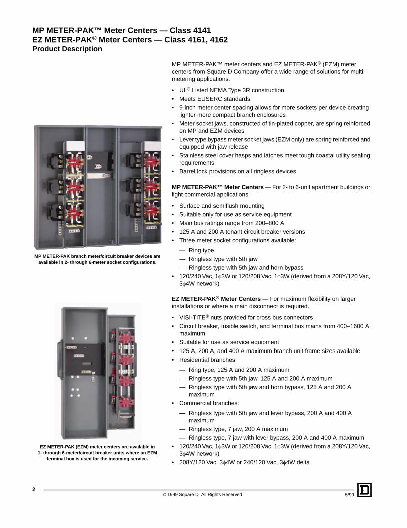
MP METER-PAK branch meter/circuit breaker devices are available in 2- through 6-meter socket configurations.
EZ METER-PAK (EZM) meter centers are available in 1- through 6-meter/circuit breaker units where an EZM
terminal box is used for the incoming service.
MP METER-PAK™ Meter Centers — Class 4141EZ METER-PAK
®
Meter Centers — Class 4161, 4162
Product Description
3
5/99 © 1999 Square D All Rights Reserved
Short Circuit Current Rating Selection Process
1. Review local utility requirements to ensure that metering equipment meets their standards.
2. Check with local utility to determine available fault current at the meter center.
3. Use the SCCR table (refer to pages 4 and 5):
A. Select meter center configuration: Main Lugs only (6-Subdivision Rule), Remote Main, Main Circuit Breaker, or Main Fusible Switch.
B. Read down to select SCCR equal to or greater than desired rating.
C. Read across to select Main Device type.
D. Read across to select Tenant Circuit Breaker type.
4. With information obtained from Step 3, turn to the appropriate selection pages to determine catalog numbers for Main Device and Tenant Circuit Breakers.
5. Refer to “Square D Certified Ratings” table below.
Square D Certified Ratings
Use this table to determine suitable load centers or panelboards installed downstream from any UL Listed EZM meter center applied on a system capable of delivering greater than 10,000 RMS symmetrical amperes. Requires a minimum of 20 feet (6.10 mm) of cable between meter center and downstream load center or panelboard. All ratings verified by actual Square D tests.
Meter Center 125 A and 200 A Branch Units
QO
®
Load Centers or NQOD Panelboardswith Branch Circuit Breakers rated 10,000 AIR
HOM Load Centerswith Branch Circuit Breakers
rated 10,000 AIR
DownstreamSingle-Phase Load Centeror Panelboard
QO, QOB: 1-Pole (15–70 A)QOT: 1-Pole (15–70 A)QO-GFI, QOB-GFI: 1-Pole (15–30 A)QO-AFI, QOB-AFI: 1-Pole (15–20 A)QO-QOB: 2-Pole (15–125 A)
HOM: 1-Pole (15–50 A)HOMT: 1-Pole (15–20 A)HOM-GFI: 1-Pole (15–20 A)HOM-AFI: 1-Pole (15-20 A)HOM: 2-Pole (15–70 A)HOMT: 2-Pole (15–30 A)
DownstreamThree-Phase Load Centeror Panelboard
QO, QOB: 1-Pole (15–70 A)2-Pole (15–125 A)3-Pole (15–100 A)
QO-GFI, QOB-GFI: 1-Pole (15–30 A)QO-AFI, QOB-AFI: 1-Pole (15–20 A)
MP METER-PAK™ Meter Centers — Class 4141EZ METER-PAK
®
Meter Centers — Class 4161, 4162
Product Description
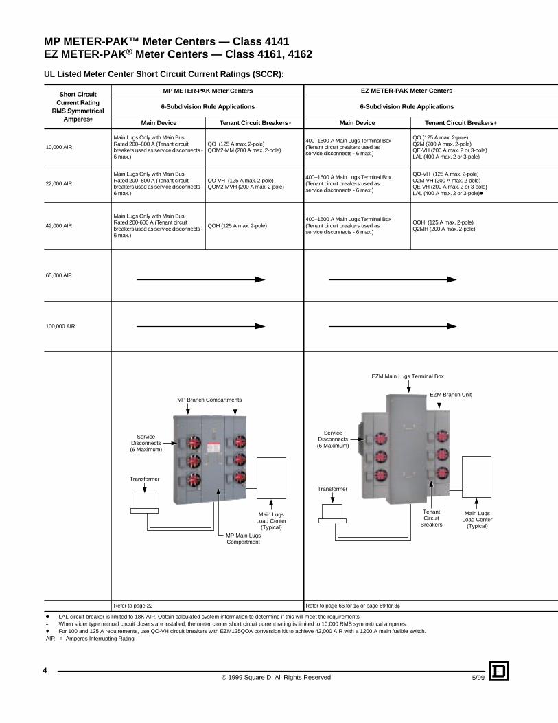
UL Listed Meter Center Short Circuit Current Ratings (SCCR):
Short CircuitCurrent Rating
RMS Symmetrical Amperes
u
MP METER-PAK Meter Centers EZ METER-PAK Meter Centers
6-Subdivision Rule Applications 6-Subdivision Rule Applications
Main Device Tenant Circuit Breakers
u
Main Device Tenant Circuit Breakers
u
10,000 AIR
Main Lugs Only with Main Bus Rated 200–800 A (Tenant circuit breakers used as service disconnects - 6 max.)
QO (125 A max. 2-pole) QOM2-MM (200 A max. 2-pole)
400–1600 A Main Lugs Terminal Box(Tenant circuit breakers used as service disconnects - 6 max.)
QO (125 A max. 2-pole)Q2M (200 A max. 2-pole)QE-VH (200 A max. 2 or 3-pole)LAL (400 A max. 2 or 3-pole)
22,000 AIR
Main Lugs Only with Main Bus Rated 200–800 A (Tenant circuit breakers used as service disconnects - 6 max.)
QO-VH (125 A max. 2-pole) QOM2-MVH (200 A max. 2-pole)
400–1600 A Main Lugs Terminal Box(Tenant circuit breakers used as service disconnects - 6 max.)
QO-VH (125 A max. 2-pole)Q2M-VH (200 A max. 2-pole)QE-VH (200 A max. 2 or 3-pole)LAL (400 A max. 2 or 3-pole)
k
42,000 AIR
Main Lugs Only with Main Bus Rated 200-600 A (Tenant circuit breakers used as service disconnects - 6 max.)
QOH (125 A max. 2-pole)400–1600 A Main Lugs Terminal Box(Tenant circuit breakers used as service disconnects - 6 max.)
QOH (125 A max. 2-pole)Q2MH (200 A max. 2-pole)
65,000
AIR
100,000 AIR
Refer to page 22 Refer to page 66 for 1
f
or page 69 for 3
f
k
LAL circuit breaker is limited to 18K AIR. Obtain calculated system information to determine if this will meet the requirements.
u
When slider type manual circuit closers are installed, the meter center short circuit current rating is limited to 10,000 RMS symmetrical amperes.
t
For 100 and 125 A requirements, use QO-VH circuit breakers with EZM125QOA conversion kit to achieve 42,000 AIR with a 1200 A main fusible switch.AIR = Amperes Interrupting Rating
Main LugsLoad Center
(Typical)
Transformer
ServiceDisconnects(6 Maximum)
MP Main LugsCompartment
MP Branch Compartments
Transformer
Main LugsLoad Center
(Typical)
TenantCircuit
Breakers
ServiceDisconnects(6 Maximum)
EZM Main Lugs Terminal Box
EZM Branch Unit
© 1999 Square D All Rights Reserved
4
5/99
MP METER-PAK™ Meter Centers — Class 4141EZ METER-PAK
®
Meter Centers — Class 4161, 4162
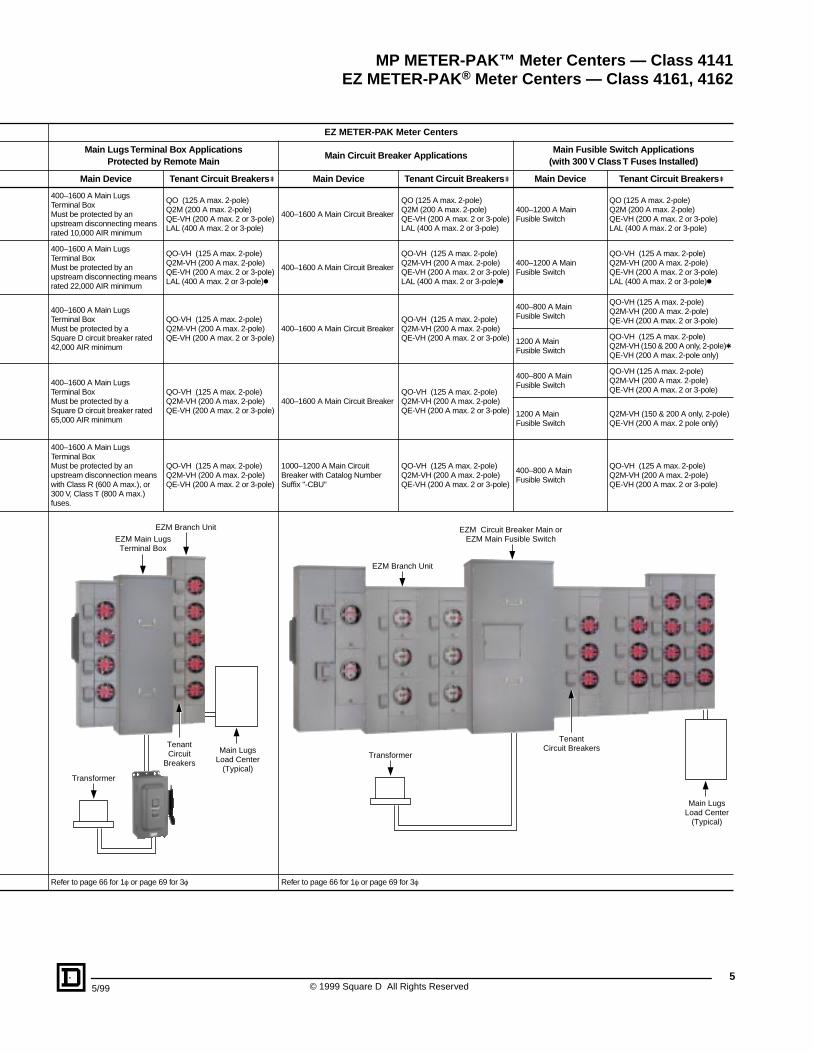
EZ METER-PAK Meter Centers
Main Lugs Terminal Box ApplicationsProtected by Remote Main
Main Circuit Breaker ApplicationsMain Fusible Switch Applications
(with 300 V Class T Fuses Installed)
Main Device Tenant Circuit Breakers u Main Device Tenant Circuit Breakers u Main Device Tenant Circuit Breakers u
400–1600 A Main Lugs Terminal BoxMust be protected by an upstream disconnecting means rated 10,000 AIR minimum
QO (125 A max. 2-pole)Q2M (200 A max. 2-pole)QE-VH (200 A max. 2 or 3-pole)LAL (400 A max. 2 or 3-pole)
400–1600 A Main Circuit Breaker
QO (125 A max. 2-pole)Q2M (200 A max. 2-pole)QE-VH (200 A max. 2 or 3-pole)LAL (400 A max. 2 or 3-pole)
400–1200 A Main Fusible Switch
QO (125 A max. 2-pole)Q2M (200 A max. 2-pole)QE-VH (200 A max. 2 or 3-pole)LAL (400 A max. 2 or 3-pole)
400–1600 A Main Lugs Terminal BoxMust be protected by an upstream disconnecting means rated 22,000 AIR minimum
QO-VH (125 A max. 2-pole)Q2M-VH (200 A max. 2-pole)QE-VH (200 A max. 2 or 3-pole)LAL (400 A max. 2 or 3-pole)k
400–1600 A Main Circuit Breaker
QO-VH (125 A max. 2-pole)Q2M-VH (200 A max. 2-pole)QE-VH (200 A max. 2 or 3-pole)LAL (400 A max. 2 or 3-pole)k
400–1200 A Main Fusible Switch
QO-VH (125 A max. 2-pole)Q2M-VH (200 A max. 2-pole)QE-VH (200 A max. 2 or 3-pole)LAL (400 A max. 2 or 3-pole)k
400–1600 A Main Lugs Terminal BoxMust be protected by a Square D circuit breaker rated 42,000 AIR minimum
QO-VH (125 A max. 2-pole) Q2M-VH (200 A max. 2-pole)QE-VH (200 A max. 2 or 3-pole)
400–1600 A Main Circuit Breaker QO-VH (125 A max. 2-pole)Q2M-VH (200 A max. 2-pole)QE-VH (200 A max. 2 or 3-pole)
400–800 A Main Fusible Switch
QO-VH (125 A max. 2-pole)Q2M-VH (200 A max. 2-pole)QE-VH (200 A max. 2 or 3-pole)
1200 A Main Fusible Switch
QO-VH (125 A max. 2-pole)Q2M-VH (150 & 200 A only, 2-pole)tQE-VH (200 A max. 2-pole only)
400–1600 A Main Lugs Terminal BoxMust be protected by a Square D circuit breaker rated 65,000 AIR minimum
QO-VH (125 A max. 2-pole)Q2M-VH (200 A max. 2-pole)QE-VH (200 A max. 2 or 3-pole)
400–1600 A Main Circuit Breaker QO-VH (125 A max. 2-pole)Q2M-VH (200 A max. 2-pole)QE-VH (200 A max. 2 or 3-pole)
400–800 A Main Fusible Switch
QO-VH (125 A max. 2-pole)Q2M-VH (200 A max. 2-pole)QE-VH (200 A max. 2 or 3-pole)
1200 A Main Fusible Switch
Q2M-VH (150 & 200 A only, 2-pole)QE-VH (200 A max. 2 pole only)
400–1600 A Main Lugs Terminal BoxMust be protected by an upstream disconnection means with Class R (600 A max.), or 300 V, Class T (800 A max.) fuses.
QO-VH (125 A max. 2-pole)Q2M-VH (200 A max. 2-pole)QE-VH (200 A max. 2 or 3-pole)
1000–1200 A Main Circuit Breaker with Catalog Number Suffix "-CBU"
QO-VH (125 A max. 2-pole)Q2M-VH (200 A max. 2-pole)QE-VH (200 A max. 2 or 3-pole)
400–800 A Main Fusible Switch
QO-VH (125 A max. 2-pole)Q2M-VH (200 A max. 2-pole)QE-VH (200 A max. 2 or 3-pole)
Refer to page 66 for 1f or page 69 for 3f Refer to page 66 for 1f or page 69 for 3f
Main LugsLoad Center
(Typical)Transformer
TenantCircuit
Breakers
EZM Main LugsTerminal Box
EZM Branch Unit
Main LugsLoad Center
(Typical)
Transformer
TenantCircuit Breakers
EZM Circuit Breaker Main orEZM Main Fusible Switch
EZM Branch Unit
55/99 © 1999 Square D All Rights Reserved
MP METER-PAK™ Meter Centers — Class 4141EZ METER-PAK® Meter Centers — Class 4161, 4162
© 1999 Square D All Rights Reserved
6
5/99
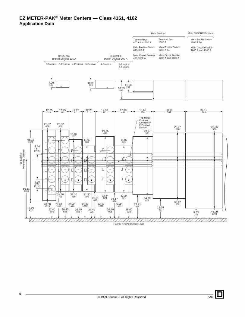
Main EUSERC Devices
Main Circuit Breaker1000 A and 1200 A
Main Fusible Switch1200 A 1f
ResidentialBranch Devices 200 A
2-Position3-Position
4-Position
Main Devices
Terminal Box1600 A
Main Fusible Switch1200 A 1f
Main Circuit Breaker1200 A and 1600 A
Terminal Box400 A and 800 A
Main Fusible Switch400-800 A
Main Circuit Breaker400-1000 A
6-Position
7.09180
ResidentialBranch Devices 125 A
3-Position4-Position5-Position
9.53242
17.38441
17.38441
18.66474
30.19767
34.19868
22.21564 18.39
467
9.00229
(Typ.)
54.401382
36.40925
36.40925
36.40925
36.40925
36.40925
63.401610
63.401610
27.40696
40.301024
72.401839
54.401382
8.09205 11.50
29218.33466
Top
Edg
e of
Mou
ntin
g C
hann
el
16.21412
3.4487
(Typ.)
56.511435
66.121679
12.25311
25.82656
31.30795
25.82656
32.34821
19.66499
34.30871
19.67500
38.12968
23.07586
46.991194
23.06586
32.34821
11.07281
31.30795
16.82427
31.30795 25.21
640 24.17614
11.07281
12.25311
12.25311
12.25311
Floor or Finished Grade Level
Top MeterPositionOmitted on2-PositionDevice
EZ METER-PAK
®
Meter Centers — Class 4161, 4162
Application Data
7
5/99 © 1999 Square D All Rights Reserved
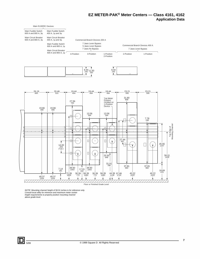
1-Position2-Position
Commercial Branch Devices 400 A
7 Jaws Lever Bypass
7 Jaws Lever Bypass5 Jaws Lever Bypass7 Jaws No Bypass
4-Position 3-Position
Commercial Branch Devices 200 A
1-Position2-Position
Main Fusible Switch600 A and 800 A, 1f
Main Circuit Breaker600 A and 800 A, 1f
Main Circuit Breaker400 A, 1f and 3f
Main Fusible Switch400 A, 1f and 3f
Main Circuit Breaker600 A and 800 A, 3f
Main Fusible Switch600 A and 800 A, 3f
Main EUSERC Devices
72.391839
7.14181
26.19665
20.46520
19.44494
19.44494
19.44494
23.21590
23.21590
14.00356
(Typ.)
30.39772
30.39772
44.391128
27.44697
18.69475
45.551157
56.511435
Top
Edg
e of
Mou
ntin
g C
hann
el40.221022
58.391483
58.391483
67.661719
9.44240 11.50
2929.44240
40.221022
Floor or Finished Grade Level
49.371254
19.66499
49.371254
19.66499
39.501003 17.01
432
31.01788
27.56700
37.81960
31.80808
37.81960
7.78198
39.501003
13.56344
25.50648
13.56344
Top MeterPositionOmitted on1-PositionDevice
NOTE: Mounting channel height of 56.51 inches is for reference only.Consult local utility for minimum and maximum meter socketheight requirements to properly position mounting channelabove grade level.
EZ METER-PAK
®
Meter Centers — Class 4161, 4162
Application Data
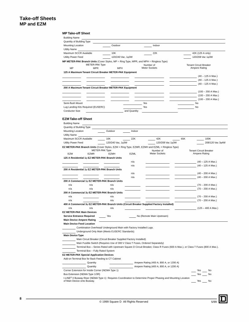
Take-off Sheets
MP and EZM
© 1999 Square D All Rights Reserved
8
5/99
MP Take-off Sheet
MP METER-PAK Branch Units
(Cover Styles, MP = Ring Type, MPR, and MPH = Ringless Type)
EZM Take-off Sheet
EZ METER-PAK Branch Units
(Cover Styles, EZM = Ring Type, EZMR, EZMH and EZML = Ringless Type)
EZ METER-PAK Main Devices
EZ METER-PAK Special Application Devices
Building Name
Quantity of Building Type
Mounting Location Outdoor Indoor
Utility Name
Maximum SCCR Available 10K 22K 42K (125 A only)
Utility Power Feed 120/240 Vac, 1
f
3W 120/208 Vac 1
f
3W
METER-PAK Type Number ofMeter Sockets
Tenant Circuit BreakerAmpere RatingMP MPR MPH
125 A Maximum Tenant Circuit Breaker METER-PAK Equipment
(40 – 125 A Max.)
(40 – 125 A Max.)
(40 – 125 A Max.)
200 A Maximum Tenant Circuit Breaker METER-PAK Equipment
(100 – 200 A Max.)
(100 – 200 A Max.)
(100 – 200 A Max.)
Semi-flush Mount Yes No
Lug Landing Kits Required (EUSERC) Yes No
Conductor Size and Quantity
Building Name
Quantity of Building Type
Mounting Location Outdoor Indoor
Utility Name
Maximum SCCR Available 10K 22K 42K 65K 100K
Utility Power Feed 120/240 Vac, 1
f
3W 120/208 Vac 1
f
3W 208/120 Vac 3
f
4W
METER-PAK Type Number ofMeter Sockets
Tenant Circuit BreakerAmpere RatingEZM EZMR EZMH EZML
125 A Residential 1
f
EZ METER-PAK Branch Units
n/a (40 – 125 A Max.)
n/a (40 – 125 A Max.)
200 A Residential 1
f
EZ METER-PAK Branch Units
n/a (40 – 200 A Max.)
n/a (40 – 200 A Max.)
200 A Commercial 1
f
EZ METER-PAK Branch Units
n/a n/a n/a (70 – 200 A Max.)
n/a n/a n/a (70 – 200 A Max.)
200 A Commercial 3
f
EZ METER-PAK Branch Units
n/a n/a (70 – 200 A Max.)
n/a n/a (70 – 200 A Max.)
400 A Commercial 3
f
EZ METER-PAK Branch Units (Circuit Breaker Supplied Factory Installed)
n/a n/a n/a (125 – 400 A Max.)
Service Entrance Required
Yes No (Remote Main Upstream)
Main Device Ampere Rating
Main Device Feed Location
Combination Overhead/ Underground Main with Factory Installed Lugs.
Underground Only Main (Meets EUSERC Standards).
Main Device Type
Main Circuit Breaker (Circuit Breaker Supplied Factory Installed)
Main Fusible Switch (Requires Use of 300 V Class T Fuses, Ordered Separately)
Terminal Box – Series Rated with Upstream Square D Circuit Breaker, Class R Fuses (600 A Max.), or Class T Fuses (800 A Max.).
Terminal Box – Fully Rated System
Add-on Terminal Box for Back Feeding to CT Cabinet
Quantity Ampere Rating (400 A, 800 A, or 1200 A)
Quantity Ampere Rating (400 A, 800 A, or 1200 A)
Corner Extension for Inside Corner (NEMA Type 1) Yes No
Bus Extension (NEMA Type 1/3R) Yes No
I-LINE
®
II Busway Riser (NEMA Type 1) Requires Coordination to Determine Proper Phasing and Mounting Location of Main Device onto Busway. Yes No
9
5/99 © 1999 Square D All Rights Reserved
Application Data—MP METER-PAK Meter Centers
125 A Maximum MP METER-PAK Meter Center Configurations . . . . 11200 A Maximum MP METER-PAK Meter Center Configurations . . . . 11Type . . . . . . . . . . . . . . . . . . . . . . . . . . . . . . . . . . . . . . . . . . . . . . . . . . 12Service . . . . . . . . . . . . . . . . . . . . . . . . . . . . . . . . . . . . . . . . . . . . . . . . 12Mains Rating . . . . . . . . . . . . . . . . . . . . . . . . . . . . . . . . . . . . . . . . . . . 12Branch Circuit Breaker Provisions . . . . . . . . . . . . . . . . . . . . . . . . . . . 12Meter Sockets . . . . . . . . . . . . . . . . . . . . . . . . . . . . . . . . . . . . . . . . . . 13Meter Socket Covers . . . . . . . . . . . . . . . . . . . . . . . . . . . . . . . . . . . . . 14Mounting Channel . . . . . . . . . . . . . . . . . . . . . . . . . . . . . . . . . . . . . . . 16Swingable Mounting Feet . . . . . . . . . . . . . . . . . . . . . . . . . . . . . . . . . 16Top Endwall Configurations . . . . . . . . . . . . . . . . . . . . . . . . . . . . . . . . 17125 A Maximum MP METER-PAK Meter Center Top Endwalls . . . . 17200 A Maximum MP METER-PAK Meter Center Top Endwalls . . . . 17Semiflush Flange Kits . . . . . . . . . . . . . . . . . . . . . . . . . . . . . . . . . . . . 17Main Lugs Section Service Conductor Terminals Data . . . . . . . . . . . 19Alternate Lug Kits . . . . . . . . . . . . . . . . . . . . . . . . . . . . . . . . . . . . . . . 19NEMA/EUSERC Lug Landing Kit . . . . . . . . . . . . . . . . . . . . . . . . . . . 19Tenant Circuit Breaker Terminal Data . . . . . . . . . . . . . . . . . . . . . . . . 20Load Neutral and Equipment Grounding Terminal Data . . . . . . . . . . 20125 A Maximum MP METER-PAK Meter Centers . . . . . . . . . . . . . . 20200 A Maximum MP METER-PAK Meter Centers . . . . . . . . . . . . . . 20Hinged Rain Channel . . . . . . . . . . . . . . . . . . . . . . . . . . . . . . . . . . . . 20
Selection
. . . . . . . . . . . . . . . . . . . . . . . . . . . . . . . . . . . . . . . . . . . . . . . . . . 21
Dimensions and Knockouts
. . . . . . . . . . . . . . . . . . . . . . . . . . . . . . . . . . 24
Wiring Diagrams
. . . . . . . . . . . . . . . . . . . . . . . . . . . . . . . . . . . . . . . . . . . . 30
MP METER-PAK™ Meter Centers — Class 4141
Contents
© 1999 Square D All Rights Reserved
10
5/99
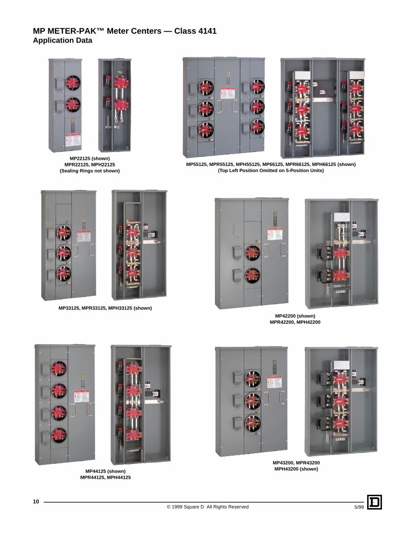
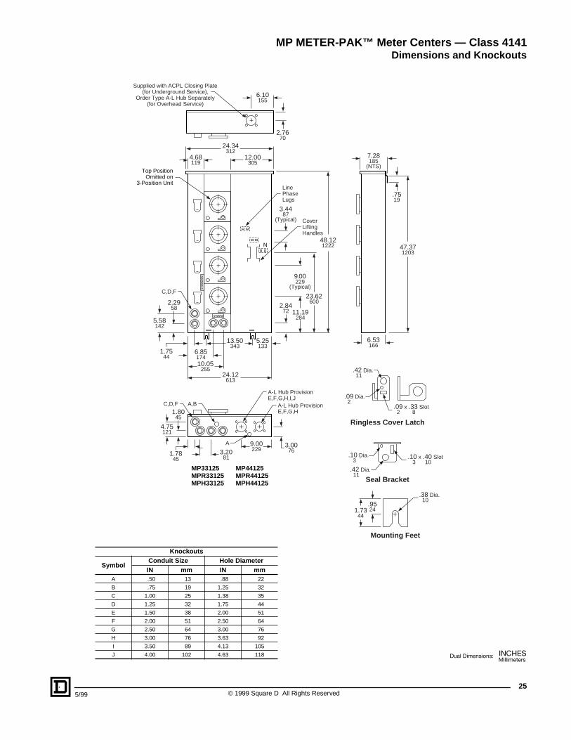
MP22125 (shown)MPR22125, MPH22125
(Sealing Rings not shown)
MP33125, MPR33125, MPH33125 (shown)
MP44125 (shown)MPR44125, MPH44125
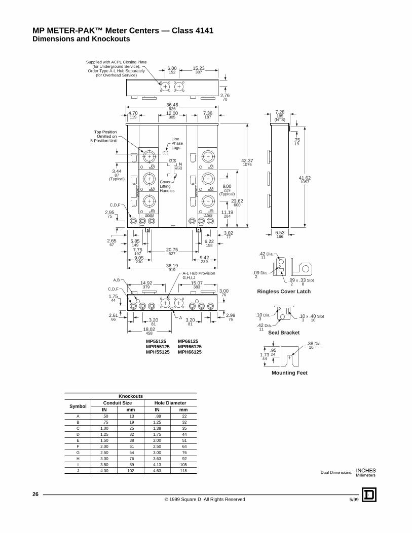
MP55125, MPR55125, MPH55125, MP66125, MPR66125, MPH66125 (shown)(Top Left Position Omitted on 5-Position Units)
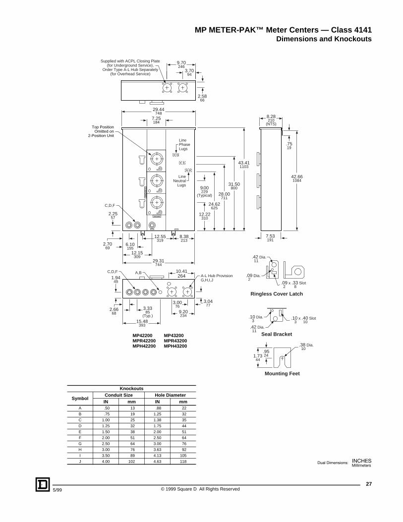
MP42200 (shown)MPR42200, MPH42200
MP43200, MPR43200MPH43200 (shown)
MP METER-PAK™ Meter Centers — Class 4141
Application Data
11
5/99 © 1999 Square D All Rights Reserved
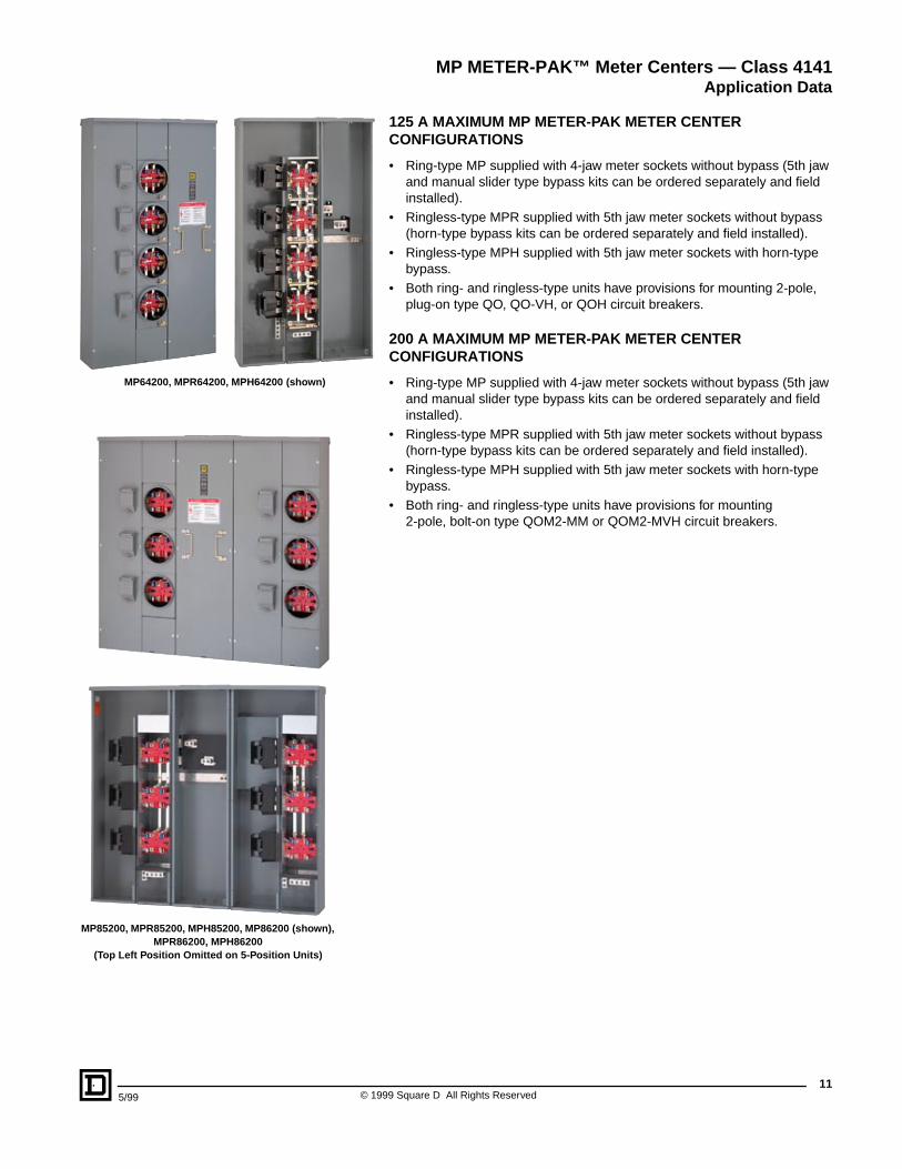
125 A MAXIMUM MP METER-PAK METER CENTER CONFIGURATIONS
• Ring-type MP supplied with 4-jaw meter sockets without bypass (5th jaw and manual slider type bypass kits can be ordered separately and field installed).
• Ringless-type MPR supplied with 5th jaw meter sockets without bypass (horn-type bypass kits can be ordered separately and field installed).
• Ringless-type MPH supplied with 5th jaw meter sockets with horn-type bypass.
• Both ring- and ringless-type units have provisions for mounting 2-pole, plug-on type QO, QO-VH, or QOH circuit breakers.
200 A MAXIMUM MP METER-PAK METER CENTER CONFIGURATIONS
• Ring-type MP supplied with 4-jaw meter sockets without bypass (5th jaw and manual slider type bypass kits can be ordered separately and field installed).
• Ringless-type MPR supplied with 5th jaw meter sockets without bypass (horn-type bypass kits can be ordered separately and field installed).
• Ringless-type MPH supplied with 5th jaw meter sockets with horn-type bypass.
• Both ring- and ringless-type units have provisions for mounting 2-pole, bolt-on type QOM2-MM or QOM2-MVH circuit breakers.
MP METER-PAK™ Meter Centers — Class 4141
Application Data
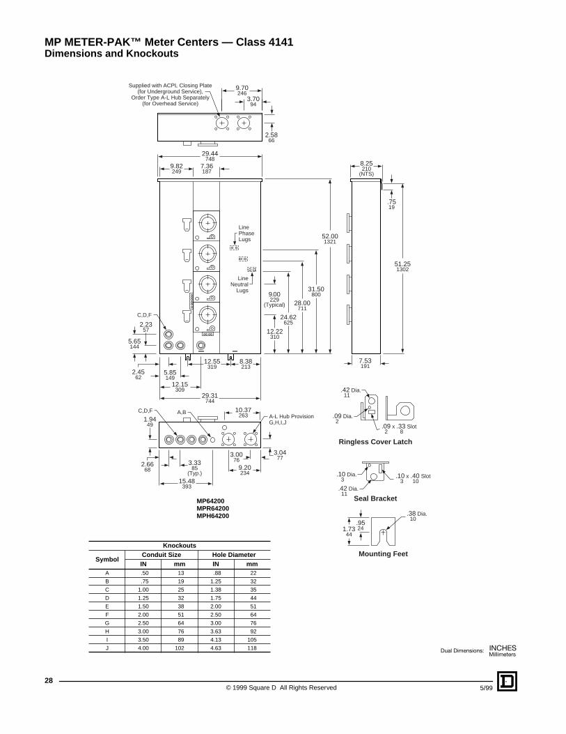
MP64200, MPR64200, MPH64200 (shown)
MP85200, MPR85200, MPH85200, MP86200 (shown), MPR86200, MPH86200
(Top Left Position Omitted on 5-Position Units)
© 1999 Square D All Rights Reserved
12
5/99
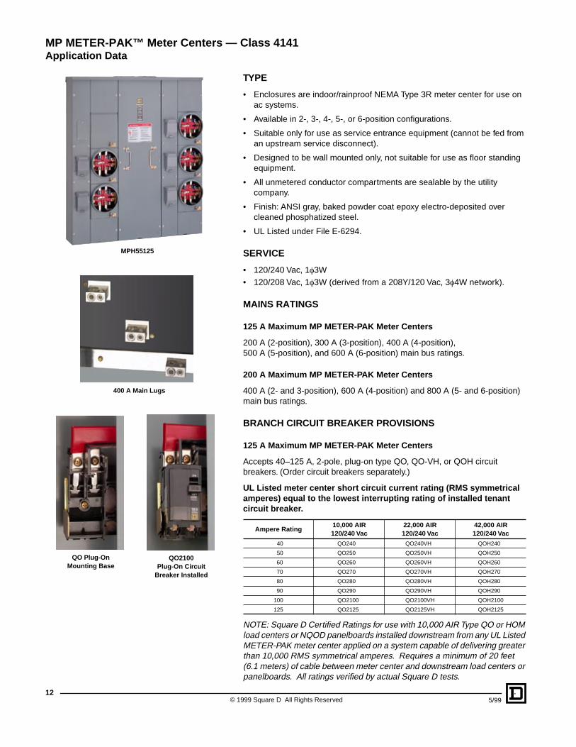
TYPE
• Enclosures are indoor/rainproof NEMA Type 3R meter center for use on ac systems.
• Available in 2-, 3-, 4-, 5-, or 6-position configurations.
• Suitable only for use as service entrance equipment (cannot be fed from an upstream service disconnect).
• Designed to be wall mounted only, not suitable for use as floor standing equipment.
• All unmetered conductor compartments are sealable by the utility company.
• Finish: ANSI gray, baked powder coat epoxy electro-deposited over cleaned phosphatized steel.
• UL Listed under File E-6294.
SERVICE
• 120/240 Vac, 1
f
3W• 120/208 Vac, 1
f
3W (derived from a 208Y/120 Vac, 3
f
4W network).
MAINS RATINGS
125 A Maximum MP METER-PAK Meter Centers
200 A (2-position), 300 A (3-position), 400 A (4-position), 500 A (5-position), and 600 A (6-position) main bus ratings.
200 A Maximum MP METER-PAK Meter Centers
400 A (2- and 3-position), 600 A (4-position) and 800 A (5- and 6-position) main bus ratings.
BRANCH CIRCUIT BREAKER PROVISIONS
125 A Maximum MP METER-PAK Meter Centers
Accepts 40–125 A, 2-pole, plug-on type QO, QO-VH, or QOH circuit breakers. (Order circuit breakers separately.)
UL Listed meter center short circuit current rating (RMS symmetrical amperes) equal to the lowest interrupting rating of installed tenant circuit breaker.
NOTE: Square D Certified Ratings for use with 10,000 AIR Type QO or HOM load centers or NQOD panelboards installed downstream from any UL Listed METER-PAK meter center applied on a system capable of delivering greater than 10,000 RMS symmetrical amperes. Requires a minimum of 20 feet (6.1 meters) of cable between meter center and downstream load centers or panelboards. All ratings verified by actual Square D tests.
Ampere Rating10,000 AIR120/240 Vac
22,000 AIR120/240 Vac
42,000 AIR120/240 Vac
40 QO240 QO240VH QOH240
50 QO250 QO250VH QOH250
60 QO260 QO260VH QOH260
70 QO270 QO270VH QOH270
80 QO280 QO280VH QOH280
90 QO290 QO290VH QOH290
100 QO2100 QO2100VH QOH2100
125 QO2125 QO2125VH QOH2125
400 A Main Lugs
MPH55125
QO Plug-On Mounting Base
QO2100Plug-On Circuit
Breaker Installed
MP METER-PAK™ Meter Centers — Class 4141
Application Data
13
5/99 © 1999 Square D All Rights Reserved
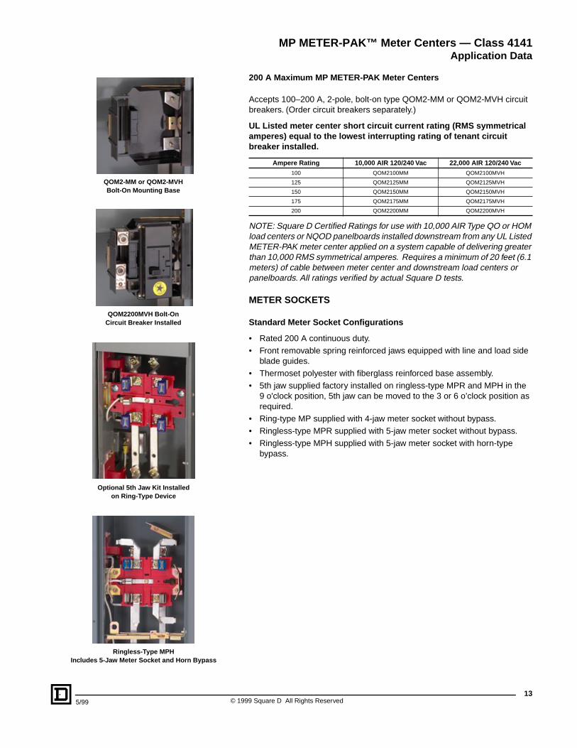
200 A Maximum MP METER-PAK Meter Centers
Accepts 100–200 A, 2-pole, bolt-on type QOM2-MM or QOM2-MVH circuit breakers. (Order circuit breakers separately.)
UL Listed meter center short circuit current rating (RMS symmetrical amperes) equal to the lowest interrupting rating of tenant circuit breaker installed.
NOTE: Square D Certified Ratings for use with 10,000 AIR Type QO or HOM load centers or NQOD panelboards installed downstream from any UL Listed METER-PAK meter center applied on a system capable of delivering greater than 10,000 RMS symmetrical amperes. Requires a minimum of 20 feet (6.1 meters) of cable between meter center and downstream load centers or panelboards. All ratings verified by actual Square D tests.
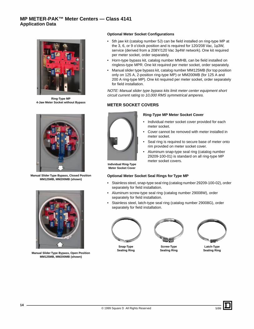
METER SOCKETS
Standard Meter Socket Configurations
• Rated 200 A continuous duty.• Front removable spring reinforced jaws equipped with line and load side
blade guides.• Thermoset polyester with fiberglass reinforced base assembly.• 5th jaw supplied factory installed on ringless-type MPR and MPH in the
9 o'clock position, 5th jaw can be moved to the 3 or 6 o’clock position as required.
• Ring-type MP supplied with 4-jaw meter socket without bypass.• Ringless-type MPR supplied with 5-jaw meter socket without bypass.• Ringless-type MPH supplied with 5-jaw meter socket with horn-type
bypass.
Ampere Rating 10,000 AIR 120/240 Vac 22,000 AIR 120/240 Vac
100 QOM2100MM QOM2100MVH
125 QOM2125MM QOM2125MVH
150 QOM2150MM QOM2150MVH
175 QOM2175MM QOM2175MVH
200 QOM2200MM QOM2200MVH
QOM2-MM or QOM2-MVHBolt-On Mounting Base
QOM2200MVH Bolt-On Circuit Breaker Installed
Optional 5th Jaw Kit Installed on Ring-Type Device
Ringless-Type MPHIncludes 5-Jaw Meter Socket and Horn Bypass
MP METER-PAK™ Meter Centers — Class 4141
Application Data
© 1999 Square D All Rights Reserved
14
5/99
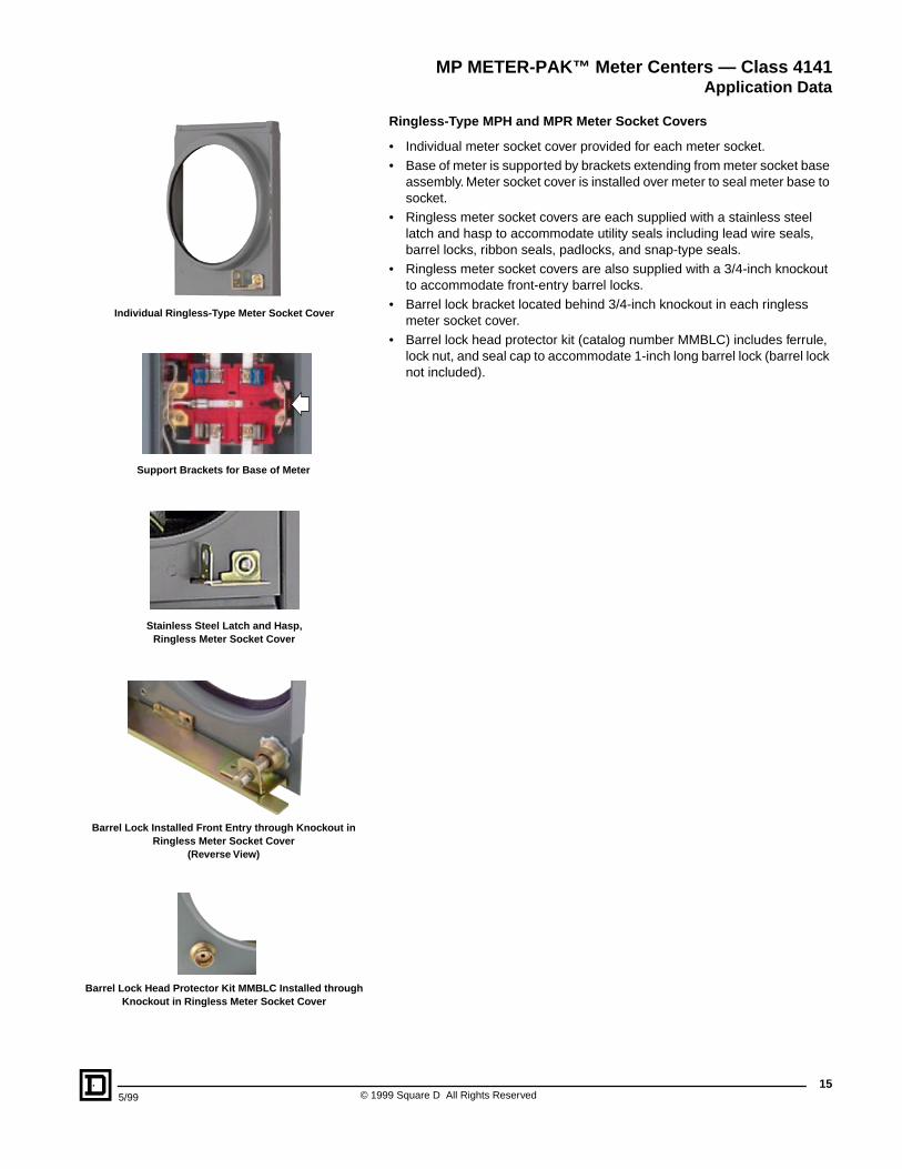
Optional Meter Socket Configurations
• 5th jaw kit (catalog number 5J) can be field installed on ring-type MP at the 3, 6, or 9 o’clock position and is required for 120/208 Vac, 1
f
3W, service (derived from a 208Y/120 Vac 3
f
4W network). One kit required per meter socket, order separately.
• Horn-type bypass kit, catalog number MMHB, can be field installed on ringless-type MPR. One kit required per meter socket, order separately.
• Manual slider type bypass kit, catalog number MM125MB (for top position only on 125 A, 2-position ring-type MP) or MM200MB (for 125 A and 200 A ring-type MP). One kit required per meter socket, order separately for field installation.
NOTE: Manual slider type bypass kits limit meter center equipment short circuit current rating to 10,000 RMS symmetrical amperes.
METER SOCKET COVERS
Ring-Type MP Meter Socket Cover
• Individual meter socket cover provided for each meter socket.
• Cover cannot be removed with meter installed in meter socket.
• Seal ring is required to secure base of meter onto rim provided on meter socket cover.
• Aluminum snap-type seal ring (catalog number 29209-100-01) is standard on all ring-type MP meter socket covers.
Optional Meter Socket Seal Rings for Type MP
• Stainless steel, snap-type seal ring (catalog number 29209-100-02), order separately for field installation.
• Aluminum screw-type seal ring (catalog number 29008W), order separately for field installation.
• Stainless steel, latch-type seal ring (catalog number 29008G), order separately for field installation.
Snap-TypeSealing Ring
Screw-Type Sealing Ring
Latch-TypeSealing Ring
Ring-Type MP4-Jaw Meter Socket without Bypass
Manual Slider Type Bypass, Closed PositionMM125MB, MM200MB (shown)
Manual Slider Type Bypass, Open PositionMM125MB, MM200MB (shown)
MP METER-PAK™ Meter Centers — Class 4141
Application Data
Individual Ring-Type Meter Socket Cover
15
5/99 © 1999 Square D All Rights Reserved
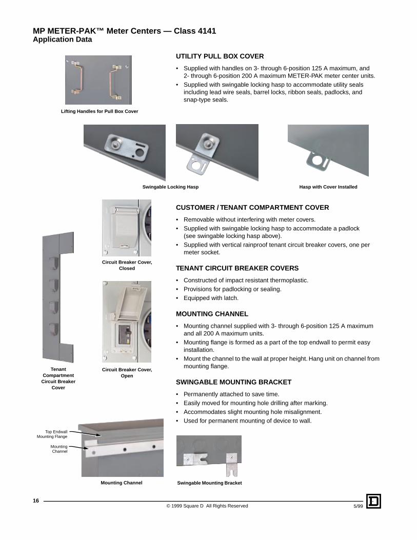
Ringless-Type MPH and MPR Meter Socket Covers
• Individual meter socket cover provided for each meter socket.• Base of meter is supported by brackets extending from meter socket base
assembly. Meter socket cover is installed over meter to seal meter base to socket.
• Ringless meter socket covers are each supplied with a stainless steel latch and hasp to accommodate utility seals including lead wire seals, barrel locks, ribbon seals, padlocks, and snap-type seals.
• Ringless meter socket covers are also supplied with a 3/4-inch knockout to accommodate front-entry barrel locks.
• Barrel lock bracket located behind 3/4-inch knockout in each ringless meter socket cover.
• Barrel lock head protector kit (catalog number MMBLC) includes ferrule, lock nut, and seal cap to accommodate 1-inch long barrel lock (barrel lock not included).
Barrel Lock Installed Front Entry through Knockout in Ringless Meter Socket Cover
(Reverse View)
Barrel Lock Head Protector Kit MMBLC Installed through Knockout in Ringless Meter Socket Cover
Stainless Steel Latch and Hasp, Ringless Meter Socket Cover
Support Brackets for Base of Meter
Individual Ringless-Type Meter Socket Cover
MP METER-PAK™ Meter Centers — Class 4141
Application Data
© 1999 Square D All Rights Reserved
16
5/99
UTILITY PULL BOX COVER
• Supplied with handles on 3- through 6-position 125 A maximum, and 2- through 6-position 200 A maximum METER-PAK meter center units.
• Supplied with swingable locking hasp to accommodate utility seals including lead wire seals, barrel locks, ribbon seals, padlocks, and snap-type seals.
CUSTOMER / TENANT COMPARTMENT COVER
• Removable without interfering with meter covers.• Supplied with swingable locking hasp to accommodate a padlock
(see swingable locking hasp above).• Supplied with vertical rainproof tenant circuit breaker covers, one per
meter socket.
TENANT CIRCUIT BREAKER COVERS
• Constructed of impact resistant thermoplastic.• Provisions for padlocking or sealing.• Equipped with latch.
MOUNTING CHANNEL
• Mounting channel supplied with 3- through 6-position 125 A maximum and all 200 A maximum units.
• Mounting flange is formed as a part of the top endwall to permit easy installation.
• Mount the channel to the wall at proper height. Hang unit on channel from mounting flange.
SWINGABLE MOUNTING BRACKET
• Permanently attached to save time.• Easily moved for mounting hole drilling after marking.• Accommodates slight mounting hole misalignment.• Used for permanent mounting of device to wall.
Hasp with Cover Installed
Swingable Mounting Bracket
Top EndwallMounting Flange
MountingChannel
Mounting Channel
Tenant Compartment
Circuit Breaker Cover
Circuit Breaker Cover, Open
Circuit Breaker Cover, Closed
Lifting Handles for Pull Box Cover
MP METER-PAK™ Meter Centers — Class 4141Application Data
Swingable Locking Hasp
175/99 © 1999 Square D All Rights Reserved
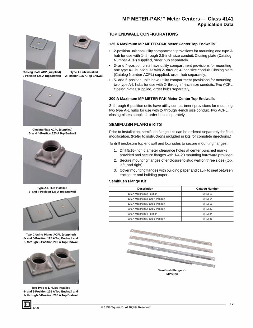
TOP ENDWALL CONFIGURATIONS
125 A Maximum MP METER-PAK Meter Center Top Endwalls
• 2-position unit has utility compartment provisions for mounting one type A hub for use with 1- through 2.5-inch size conduit. Closing plate (Catalog Number ACP) supplied, order hub separately.
• 3- and 4-position units have utility compartment provisions for mounting one type A-L hub for use with 2- through 4-inch size conduit. Closing plate (Catalog Number ACPL) supplied, order hub separately.
• 5- and 6-position units have utility compartment provisions for mounting two type A-L hubs for use with 2- through 4-inch size conduits. Two ACPL closing plates supplied, order hubs separately.
200 A Maximum MP METER-PAK Meter Center Top Endwalls
2- through 6-position units have utility compartment provisions for mounting two type A-L hubs for use with 2- through 4-inch size conduit. Two ACPL closing plates supplied, order hubs separately.
SEMIFLUSH FLANGE KITS
Prior to installation, semiflush flange kits can be ordered separately for field modification. (Refer to instructions included in kits for complete directions.)
To drill enclosure top endwall and box sides to secure mounting flanges:
1. Drill 5/16-inch diameter clearance holes at center punched marks provided and secure flanges with 1/4-20 mounting hardware provided.
2. Secure mounting flanges of enclosure to stud wall on three sides (top, left, and right).
3. Cover mounting flanges with building paper and caulk to seal between enclosure and building paper.
Semiflush Flange Kit
Description Catalog Number
125 A Maximum 2-Position MPSF12
125 A Maximum 3- and 4-Position MPSF14
125 A Maximum 5- and 6-Position MPSF16
200 A Maximum 2- and 3-Position MPSF23
200 A Maximum 4-Position MPSF24
200 A Maximum 5- and 6-Position MPSF26
Semiflush Flange Kit MPSF23
Closing Plate ACP (supplied)2-Position 125 A Top Endwall
Type A Hub Installed2-Position 125 A Top Endwall
Closing Plate ACPL (supplied)3- and 4-Position 125 A Top Endwall
Type A-L Hub Installed3- and 4-Position 125 A Top Endwall
Two Type A-L Hubs Installed5- and 6-Position 125 A Top Endwall and 2- through 6-Position 200 A Top Endwall
Two Closing Plates ACPL (supplied)5- and 6-Position 125 A Top Endwall and 2- through 6-Position 200 A Top Endwall
MP METER-PAK™ Meter Centers — Class 4141Application Data
© 1999 Square D All Rights Reserved18
5/99
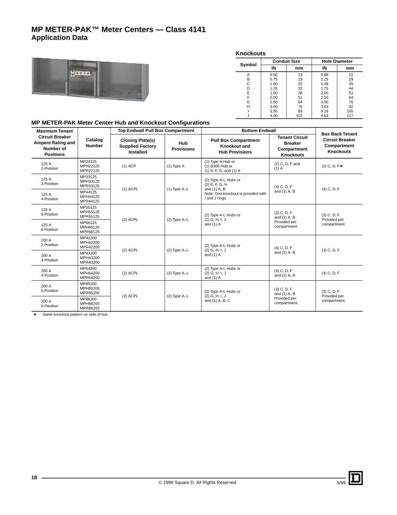
Knockouts
SymbolConduit Size Hole Diameter
IN mm IN mmA 0.50 13 0.88 22B 0.75 19 1.25 29C 1.00 25 1.38 35D 1.25 32 1.75 44E 1.50 38 2.00 51F 2.00 51 2.50 64G 2.50 64 3.00 76H 3.00 76 3.63 92I 3.50 89 4.19 105J 4.00 102 4.63 117
MP METER-PAK Meter Center Hub and Knockout ConfigurationsMaximum Tenant Circuit Breaker
Ampere Rating and Number of Positions
CatalogNumber
Top Endwall Pull Box Compartment Bottom EndwallBox Back Tenant Circuit Breaker Compartment
Knockouts
Closing Plate(s) Supplied Factory
Installed
Hub Provisions
Pull Box Compartment Knockout and
Hub Provisions
Tenant Circuit Breaker
Compartment Knockouts
125 A2-Position
MP22125(1) ACP (1) Type A
(1) Type A Hub or(1) B300 Hub or(1) D, F, G, and (1) A
(2) C, D, F and(1) A
(2) C, D, FaMPH22125MPR22125
125 A3-Position
MP33125
(1) ACPL (1) Type A–L
(2) Type A-L Hubs or(2) E, F, G, Hand (1) A, BNote: One knockout is provided with I and J rings.
(4) C, D, Fand (1) A, B
(4) C, D, F
MPH33125MPR33125
125 A4-Position
MP44125MPH44125MPR44125
125 A5-Position
MP55125
(2) ACPL (2) Type A–L(2) Type A-L Hubs or(2) G, H, I, Jand (1) A
(3) C, D, Fand (1) A, BProvided per compartment.
(3) C, D, FProvided per compartment.
MPH55125MPR55125
125 A6-Position
MP66125MPH66125MPR66125
200 A2-Position
MP42200
(2) ACPL (2) Type A–L(2) Type A-L Hubs or(2) G, H, I, Jand (1) A
(4) C, D, Fand (1) A, B
(3) C, D, F
MPH42200MPR42200
200 A3-Position
MP43200MPH43200MPR43200
200 A4-Position
MP64200(2) ACPL (2) Type A–L
(2) Type A-L Hubs or(2) G, H, I, Jand (1) A
(4) C, D, Fand (1) A, B
(4) C, D, FMPH64200MPR64200
200 A5-Position
MP85200
(2) ACPL (2) Type A–L(2) Type A-L Hubs or(2) G, H, I, Jand (1) A, B, C
(3) C, D, Fand (1) A, BProvided per compartment.
(3) C, D, FProvided per compartment.
MPH85200MPR85200
200 A6-Position
MP86200MPH86200MPR86200
a Same knockout pattern on side of box.
MP METER-PAK™ Meter Centers — Class 4141Application Data
195/99 © 1999 Square D All Rights Reserved
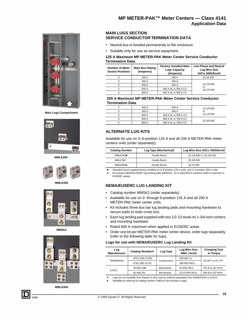
MAIN LUGS SECTIONSERVICE CONDUCTOR TERMINATION DATA
• Neutral bus is bonded permanently to the enclosure.
• Suitable only for use as service equipment.
ALTERNATE LUG KITS
Available for use on 3–6-position 125 A and all 200 A METER-PAK meter centers units (order separately):
NEMA/EUSERC LUG LANDING KIT
• Catalog number MMSK2 (order separately).• Available for use on 3- through 6-position 125 A and all 200 A
METER-PAK meter center units.• Kit includes three bus bar lug landing pads and mounting hardware to
secure pads to main cross bus.• Each lug landing pad supplied with two 1/2-13 studs on 1-3/4-inch centers
and mounting hardware.• Rated 600 A maximum when applied in EUSERC areas.• Order one kit per METER-PAK meter center device, order lugs separately
(refer to the following table for lugs).
125 A Maximum MP METER-PAK Meter Center Service Conductor Termination Data
Number of Meter Socket Positions
Main Bus Rating(Amperes)
Factory Installed Main Lugs Capacity
(Amperes)
Line Phase and Neutral Lug Wire Size
Al/Cu AWG/kcmil2 200 A 200 A (1) #4-250
3 300 A 300 A(1) 1/0-600 or(2) 1/0-250
4 400 A 400 A
5 500 A 400 A AL or 500 A CU
6 600 A 400 A AL or 500 A CU
200 A Maximum MP METER-PAK Meter Center Service Conductor Termination Data
2 400 A 400 A (1) 1/0-600or (2) 1/0-250
3 400 A 400 A
4 600 A 400 A AL or 500 A CU
5 800 A 600 A AL or 750 A CU(2) 3/0-500
6 800 A 600 A AL or 750 A CU
Catalog Number Lug Type (Mechanical) Lug Wire Size Al/Cu AWG/kcmil
MMLK250c Double Barrel (1) 1/0-600 or (2) 1/0-250
MMLK500 Double Barrel (2) 3/0-500
MMLK600q Double Barrel (2) #2-600
c Standard lug kit supplied factory installed on 3–6-position 125 A units, and 2–4-position 200 A units.q Kit includes NEMA/EUSERC lug landing pads (MMSK2). Kit is rated 800 A maximum (600 A maximum in
EUSERC areas).
Lugs for use with NEMA/EUSERC Lug Landing Kit
LugManufacturer
Catalog Number p Lug TypeLug Wire SizeAWG / kcmil
Crimping Tool or Torque
ANDERSONVHCL-600-12-BN
Compression250-600 Cu
VC-6FT or VC-7FTVCEL-060-12-H2 400-600 Al/Cu
ILSCOTA-600-2Nf Mechanical #2-600 Al/Cu 375 lb-in (42 N•m)
AU-600-2N Mechanical (2) #2-600 Al/Cu 500 lb-in (57 N•m)
p Lugs are not available from Square D and must be ordered separately from ANDERSON or ILSCO.f Available by ordering kit catalog number CMELK4 (kit includes 4 lugs).
MMLK250
MMLK500
MMSK2
MMLK600
Main Lugs Compartment
MP METER-PAK™ Meter Centers — Class 4141Application Data
© 1999 Square D All Rights Reserved20
5/99
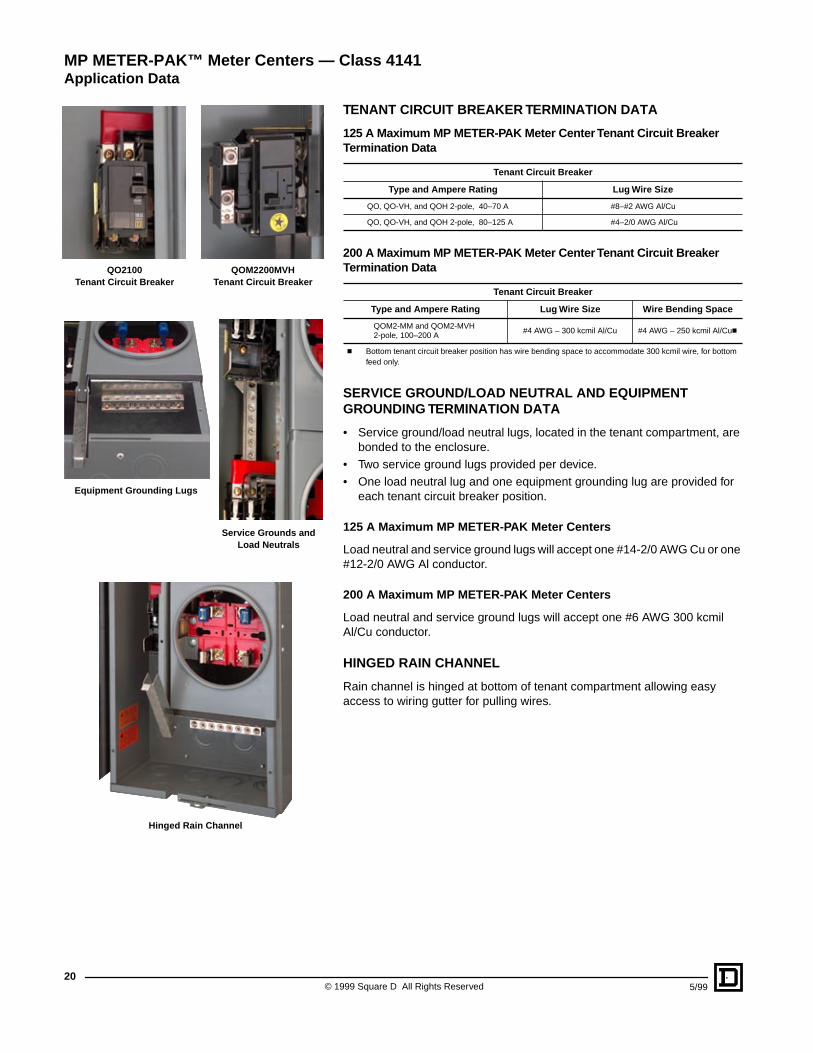
TENANT CIRCUIT BREAKER TERMINATION DATA
125 A Maximum MP METER-PAK Meter Center Tenant Circuit Breaker Termination Data
200 A Maximum MP METER-PAK Meter Center Tenant Circuit Breaker Termination Data
SERVICE GROUND/LOAD NEUTRAL AND EQUIPMENT GROUNDING TERMINATION DATA
• Service ground/load neutral lugs, located in the tenant compartment, are bonded to the enclosure.
• Two service ground lugs provided per device.• One load neutral lug and one equipment grounding lug are provided for
each tenant circuit breaker position.
125 A Maximum MP METER-PAK Meter Centers
Load neutral and service ground lugs will accept one #14-2/0 AWG Cu or one #12-2/0 AWG Al conductor.
200 A Maximum MP METER-PAK Meter Centers
Load neutral and service ground lugs will accept one #6 AWG 300 kcmil Al/Cu conductor.
HINGED RAIN CHANNEL
Rain channel is hinged at bottom of tenant compartment allowing easy access to wiring gutter for pulling wires.
Tenant Circuit Breaker
Type and Ampere Rating Lug Wire Size
QO, QO-VH, and QOH 2-pole, 40–70 A #8–#2 AWG Al/Cu
QO, QO-VH, and QOH 2-pole, 80–125 A #4–2/0 AWG Al/Cu
Tenant Circuit Breaker
Type and Ampere Rating Lug Wire Size Wire Bending Space
QOM2-MM and QOM2-MVH2-pole, 100–200 A
#4 AWG – 300 kcmil Al/Cu #4 AWG – 250 kcmil Al/Cuc
c Bottom tenant circuit breaker position has wire bending space to accommodate 300 kcmil wire, for bottom feed only.
MP METER-PAK™ Meter Centers — Class 4141Application Data
QO2100Tenant Circuit Breaker
QOM2200MVHTenant Circuit Breaker
Equipment Grounding Lugs
Service Grounds and Load Neutrals
Hinged Rain Channel
215/99 © 1999 Square D All Rights Reserved
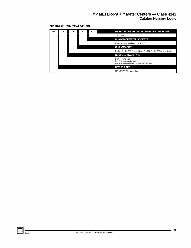
MP METER-PAK™ Meter Centers — Class 4141Catalog Number Logic
MP METER-PAK Meter Centers
MP H 4 4 125 MAXIMUM TENANT CIRCUIT BREAKER AMPERAGE
125, 200 A
NUMBER OF METER SOCKETS
Meter Sockets Available 2, 3, 4, 5, 6
BUS AMPACITY
2 = 200 A 3 = 300 A 4 = 400 A 5 = 500 A 6 = 600 A 8 = 800 A
SOCKET/BYPASS TYPE
Blank = Ring TypeR = Ringless with 5th JawH = Ringless with Horn Bypass and 5th Jaw
DEVICE NAME
MP METER-PAK Meter Center
© 1999 Square D All Rights Reserved22
5/99
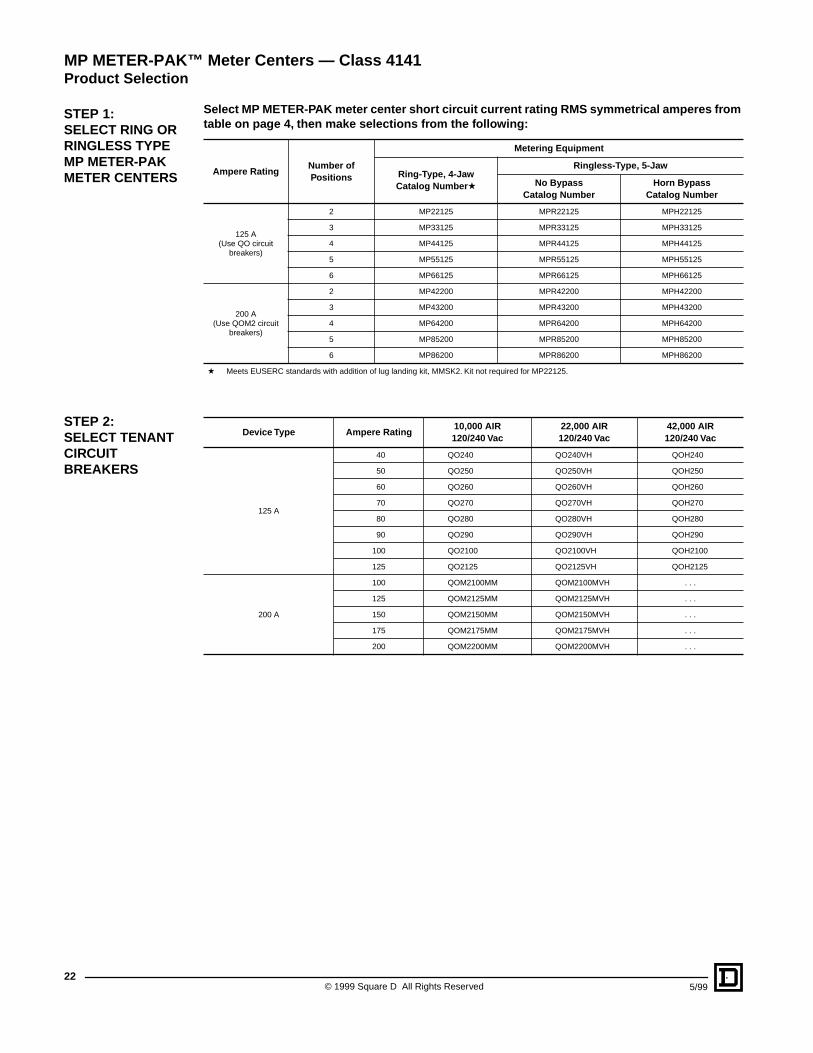
Select MP METER-PAK meter center short circuit current rating RMS symmetrical amperes from table on page 4, then make selections from the following:
Ampere RatingNumber of Positions
Metering Equipment
Ring-Type, 4-JawCatalog Number a
Ringless-Type, 5-Jaw
No Bypass Catalog Number
Horn Bypass Catalog Number
125 A(Use QO circuit
breakers)
2 MP22125 MPR22125 MPH22125
3 MP33125 MPR33125 MPH33125
4 MP44125 MPR44125 MPH44125
5 MP55125 MPR55125 MPH55125
6 MP66125 MPR66125 MPH66125
200 A(Use QOM2 circuit
breakers)
2 MP42200 MPR42200 MPH42200
3 MP43200 MPR43200 MPH43200
4 MP64200 MPR64200 MPH64200
5 MP85200 MPR85200 MPH85200
6 MP86200 MPR86200 MPH86200
a Meets EUSERC standards with addition of lug landing kit, MMSK2. Kit not required for MP22125.
Device Type Ampere Rating10,000 AIR 120/240 Vac
22,000 AIR120/240 Vac
42,000 AIR120/240 Vac
125 A
40 QO240 QO240VH QOH240
50 QO250 QO250VH QOH250
60 QO260 QO260VH QOH260
70 QO270 QO270VH QOH270
80 QO280 QO280VH QOH280
90 QO290 QO290VH QOH290
100 QO2100 QO2100VH QOH2100
125 QO2125 QO2125VH QOH2125
200 A
100 QOM2100MM QOM2100MVH . . .
125 QOM2125MM QOM2125MVH . . .
150 QOM2150MM QOM2150MVH . . .
175 QOM2175MM QOM2175MVH . . .
200 QOM2200MM QOM2200MVH . . .
STEP 1: SELECT RING OR RINGLESS TYPE MP METER-PAK METER CENTERS
STEP 2: SELECT TENANT CIRCUIT BREAKERS
MP METER-PAK™ Meter Centers — Class 4141Product Selection
235/99 © 1999 Square D All Rights Reserved
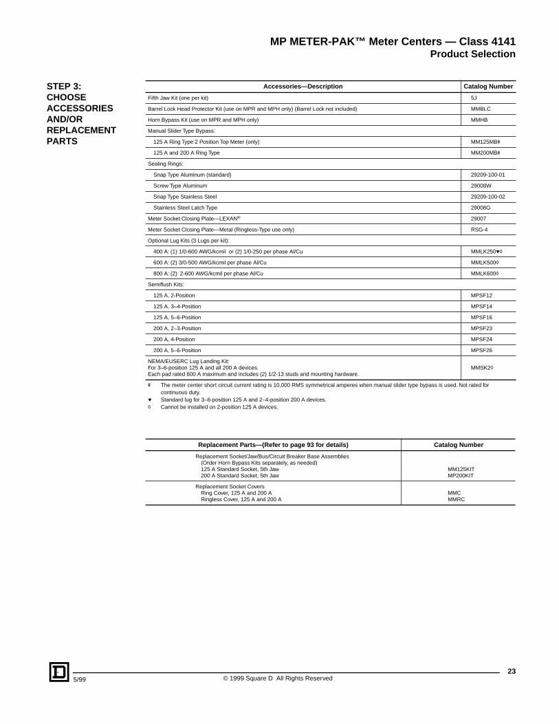
Accessories—Description Catalog Number
Fifth Jaw Kit (one per kit) 5J
Barrel Lock Head Protector Kit (use on MPR and MPH only) (Barrel Lock not included) MMBLC
Horn Bypass Kit (use on MPR and MPH only) MMHB
Manual Slider Type Bypass:
125 A Ring Type 2 Position Top Meter (only) MM125MBu
125 A and 200 A Ring Type MM200MBu
Sealing Rings:
Snap Type Aluminum (standard) 29209-100-01
Screw Type Aluminum 29008W
Snap Type Stainless Steel 29209-100-02
Stainless Steel Latch Type 29008G
Meter Socket Closing Plate—LEXAN® 29007
Meter Socket Closing Plate—Metal (Ringless-Type use only) RSG-4
Optional Lug Kits (3 Lugs per kit):
400 A: (1) 1/0-600 AWG/kcmil or (2) 1/0-250 per phase Al/Cu MMLK250ph
600 A: (2) 3/0-500 AWG/kcmil per phase Al/Cu MMLK500h
800 A: (2) 2-600 AWG/kcmil per phase Al/Cu MMLK600h
Semiflush Kits:
125 A, 2-Position MPSF12
125 A, 3–4-Position MPSF14
125 A, 5–6-Position MPSF16
200 A, 2–3-Position MPSF23
200 A, 4-Position MPSF24
200 A, 5–6-Position MPSF26
NEMA/EUSERC Lug Landing Kit:For 3–6-position 125 A and all 200 A devices. Each pad rated 600 A maximum and includes (2) 1/2-13 studs and mounting hardware.
MMSK2h
u The meter center short circuit current rating is 10,000 RMS symmetrical amperes when manual slider type bypass is used. Not rated for continuous duty.
p Standard lug for 3–6-position 125 A and 2–4-position 200 A devices.h Cannot be installed on 2-position 125 A devices.
Replacement Parts—(Refer to page 93 for details) Catalog Number
Replacement Socket/Jaw/Bus/Circuit Breaker Base Assemblies(Order Horn Bypass Kits separately, as needed)125 A Standard Socket, 5th Jaw200 A Standard Socket, 5th Jaw
MM125KITMP200KIT
Replacement Socket CoversRing Cover, 125 A and 200 ARingless Cover, 125 A and 200 A
MMCMMRC
STEP 3: CHOOSEACCESSORIES AND/OR REPLACEMENT PARTS
MP METER-PAK™ Meter Centers — Class 4141Product Selection
© 1999 Square D All Rights Reserved24
5/99
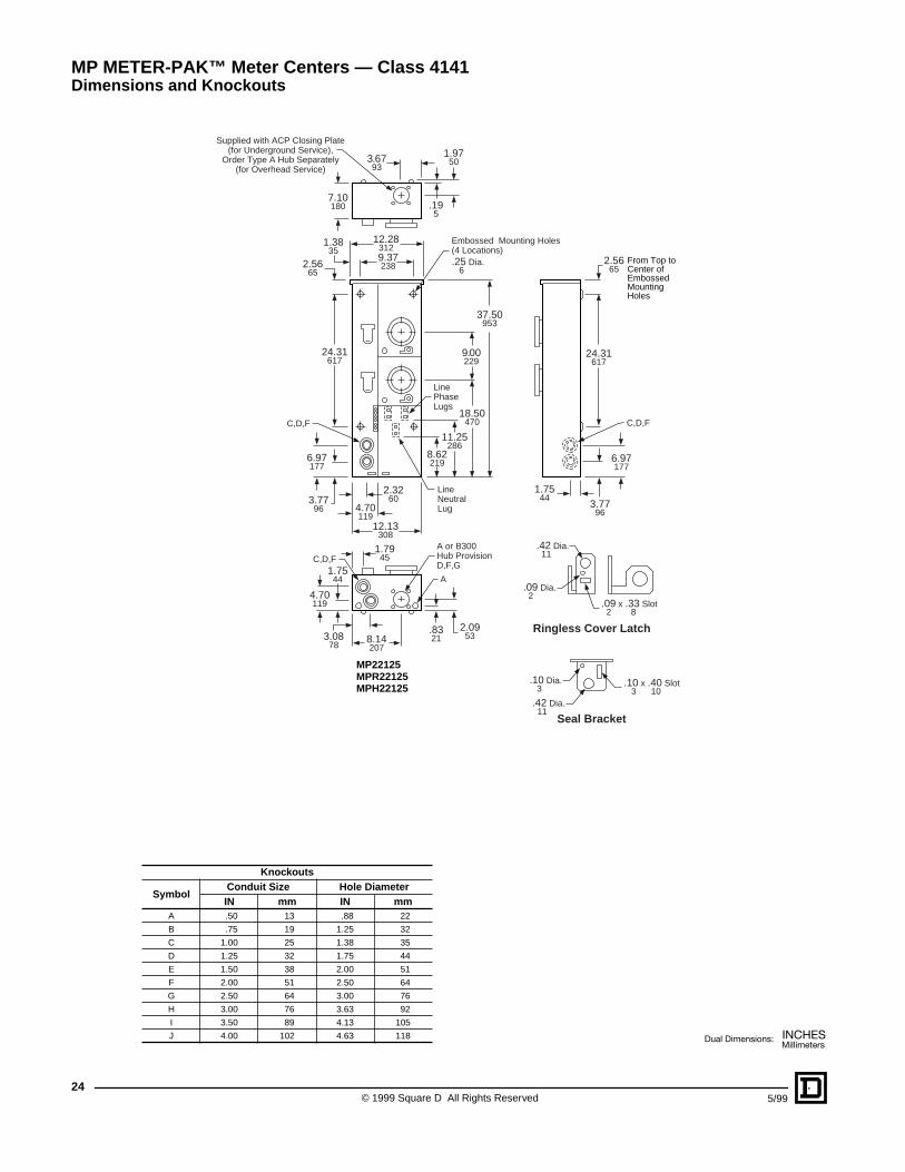
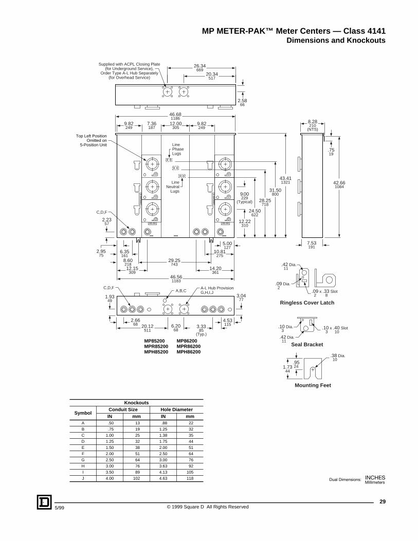
Supplied with ACP Closing Plate(for Underground Service),
Order Type A Hub Separately(for Overhead Service)
.195
1.9750
7.10180
3.6793
12.13308
12.283129.37238
37.50953
9.00229
2.3260
4.70119
3.7796
6.97177
18.50470
8.62219
3.7796
1.7544
6.97177
24.31617
11.25286
2.5665
1.3835
24.31617
A
A or B300Hub ProvisionD,F,G
LineNeutralLug
LinePhaseLugs
C,D,FC,D,F
C,D,F
4.70119
1.7544
1.7945
.83213.08
788.14207
2.0953
.09 x .33 Slot 2 8
.10 x .40 Slot 3 10
Ringless Cover Latch
.09 Dia. 2
.10 Dia. 3
.42 Dia. 11
.42 Dia. 11
Seal Bracket
Embossed Mounting Holes(4 Locations).25 Dia. 6
2.5665
MP22125MPR22125MPH22125
From Top toCenter ofEmbossedMountingHoles
Knockouts
SymbolConduit Size Hole DiameterIN mm IN mm
A .50 13 .88 22
B .75 19 1.25 32
C 1.00 25 1.38 35
D 1.25 32 1.75 44
E 1.50 38 2.00 51
F 2.00 51 2.50 64
G 2.50 64 3.00 76
H 3.00 76 3.63 92
I 3.50 89 4.13 105
J 4.00 102 4.63 118
MP METER-PAK™ Meter Centers — Class 4141Dimensions and Knockouts
255/99 © 1999 Square D All Rights Reserved
24.12613
10.05255
24.34312
12.00305
4.68119
48.121222
9.00229
(Typical)
3.4487
(Typical)
1.7544
5.25133
13.50343
6.85174
2.2958
5.58142
11.19284
2.8472
23.62600
C,D,F
LinePhaseLugs
CoverLiftingHandles
N
Top PositionOmitted on
3-Position Unit
Supplied with ACPL Closing Plate(for Underground Service),
Order Type A-L Hub Separately(for Overhead Service)
2.7670
6.10155
6.53166
47.371203
.7519
7.28185
(NTS)
A
A-L Hub ProvisionE,F,G,H,I,J
A-L Hub ProvisionE,F,G,H
C,D,F A,B
4.75121
9.00229
1.8045
3.00761.78
453.20
81
MP33125MPR33125MPH33125
MP44125MPR44125MPH44125
.95241.73
44
.09 x .33 Slot 2 8
.10 x .40 Slot 3 10
Ringless Cover Latch
.09 Dia. 2
.10 Dia. 3
.38 Dia. 10
.42 Dia. 11
.42 Dia. 11
Seal Bracket
Mounting Feet
Knockouts
SymbolConduit Size Hole DiameterIN mm IN mm
A .50 13 .88 22
B .75 19 1.25 32
C 1.00 25 1.38 35
D 1.25 32 1.75 44
E 1.50 38 2.00 51
F 2.00 51 2.50 64
G 2.50 64 3.00 76
H 3.00 76 3.63 92
I 3.50 89 4.13 105
J 4.00 102 4.63 118
MP METER-PAK™ Meter Centers — Class 4141Dimensions and Knockouts
© 1999 Square D All Rights Reserved26
5/99
36.19919
9.05230
36.46926
12.00305
4.70119
7.36187
42.371076
9.00229
(Typical)
3.4487
(Typical)
2.6567
3.0277
6.22158
9.42239
20.75527
5.851497.75197
2.9575
11.19284
23.62600C,D,F
LinePhaseLugs
CoverLiftingHandles
N
Top PositionOmitted on
5-Position Unit
Supplied with ACPL Closing Plate(for Underground Service),
Order Type A-L Hub Separately(for Overhead Service)
2.7670
6.00152
15.23387
6.53166
41.621057
.7519
7.28185
(NTS)
A
A,B
A-L Hub ProvisionG,H,I,J
C,D,F
1.7544
14.92379
3.0076
2.6166
2.9976
18.02458
15.07383
3.2081
3.2081
MP55125MPR55125MPH55125
MP66125MPR66125MPH66125 .95
241.7344
.09 x .33 Slot 2 8
.10 x .40 Slot 3 10
Ringless Cover Latch
.09 Dia. 2
.10 Dia. 3
.38 Dia. 10
.42 Dia. 11
.42 Dia. 11
Seal Bracket
Mounting Feet
Knockouts
SymbolConduit Size Hole DiameterIN mm IN mm
A .50 13 .88 22
B .75 19 1.25 32
C 1.00 25 1.38 35
D 1.25 32 1.75 44
E 1.50 38 2.00 51
F 2.00 51 2.50 64
G 2.50 64 3.00 76
H 3.00 76 3.63 92
I 3.50 89 4.13 105
J 4.00 102 4.63 118
MP METER-PAK™ Meter Centers — Class 4141Dimensions and Knockouts
275/99 © 1999 Square D All Rights Reserved
12.15309
29.31744
29.44748
7.25184
43.411103
9.00229
(Typical)
2.7069
8.38213
12.55319
6.10155
2.2557
12.22310
24.62625
28.00711
31.50800
C,D,F
LinePhaseLugs
LineNeutral
Lugs
Top PositionOmitted on
2-Position Unit
Supplied with ACPL Closing Plate(for Underground Service),
Order Type A-L Hub Separately(for Overhead Service)
2.5866
3.7094
7.53191
42.661084
.7519
8.28210
(NTS)
A-L Hub ProvisionG,H,I,J
C,D,F A,B
3.0076
9.20234
10.41264
15.48393
1.9449
3.0477
2.6668
3.3385
(Typ.)
MP42200MPR42200MPH42200
MP43200MPR43200MPH43200
9.70246
.95241.73
44
.09 x .33 Slot 2 8
.10 x .40 Slot 3 10
Ringless Cover Latch
.09 Dia. 2
.10 Dia. 3
.38 Dia. 10
.42 Dia. 11
.42 Dia. 11
Seal Bracket
Mounting Feet
Knockouts
SymbolConduit Size Hole DiameterIN mm IN mm
A .50 13 .88 22
B .75 19 1.25 32
C 1.00 25 1.38 35
D 1.25 32 1.75 44
E 1.50 38 2.00 51
F 2.00 51 2.50 64
G 2.50 64 3.00 76
H 3.00 76 3.63 92
I 3.50 89 4.13 105
J 4.00 102 4.63 118
MP METER-PAK™ Meter Centers — Class 4141Dimensions and Knockouts
© 1999 Square D All Rights Reserved28
5/99
12.15309
29.31744
10.37263
29.44748
7.36187
9.82249
52.001321
9.00229
(Typical)
2.4562
8.38213
12.55319
5.85149
2.2357
5.65144
12.22310
24.62625
28.00711
31.50800
C,D,F
LinePhaseLugs
LineNeutral
Lugs
Supplied with ACPL Closing Plate(for Underground Service),
Order Type A-L Hub Separately(for Overhead Service)
2.5866
3.7094
7.53191
51.251302
.7519
8.25210
(NTS)
A-L Hub ProvisionG,H,I,J
C,D,F A,B
3.0076
9.20234
15.48393
1.9449
3.0477
2.6668
3.3385
(Typ.)
MP64200MPR64200MPH64200
9.70246
.95241.73
44
.09 x .33 Slot 2 8
.10 x .40 Slot 3 10
Ringless Cover Latch
.09 Dia. 2
.10 Dia. 3
.38 Dia. 10
.42 Dia. 11
.42 Dia. 11
Seal Bracket
Mounting Feet Knockouts
SymbolConduit Size Hole DiameterIN mm IN mm
A .50 13 .88 22
B .75 19 1.25 32
C 1.00 25 1.38 35
D 1.25 32 1.75 44
E 1.50 38 2.00 51
F 2.00 51 2.50 64
G 2.50 64 3.00 76
H 3.00 76 3.63 92
I 3.50 89 4.13 105
J 4.00 102 4.63 118
MP METER-PAK™ Meter Centers — Class 4141Dimensions and Knockouts
295/99 © 1999 Square D All Rights Reserved
8.60218
29.25743
46.561183
46.681186
7.36187
9.82249
9.82249
12.00305
43.411321
9.00229
(Typical)
2.9575
5.00127
12.15309
6.35161
10.81275
2.2357 12.22
310
24.50622
28.25718
31.50800
C,D,F
LinePhaseLugs
LineNeutral
Lugs
Supplied with ACPL Closing Plate(for Underground Service),
Order Type A-L Hub Separately(for Overhead Service)
2.5866
20.34517
7.53191
42.661084
.7519
8.28210
(NTS)
A-L Hub ProvisionG,H,I,J
C,D,FA,B,C
4.5311520.12
511
1.9349
3.0477
2.6668 3.33
85(Typ.)
6.2068
MP85200MPR85200MPH85200
26.34669
14.20361
MP86200MPR86200MPH86200
Top Left PositionOmitted on
5-Position Unit
.95241.73
44
.09 x .33 Slot 2 8
.10 x .40 Slot 3 10
Ringless Cover Latch
.09 Dia. 2
.10 Dia. 3
.38 Dia. 10
.42 Dia. 11
.42 Dia. 11
Seal Bracket
Mounting Feet
Knockouts
SymbolConduit Size Hole DiameterIN mm IN mm
A .50 13 .88 22
B .75 19 1.25 32
C 1.00 25 1.38 35
D 1.25 32 1.75 44
E 1.50 38 2.00 51
F 2.00 51 2.50 64
G 2.50 64 3.00 76
H 3.00 76 3.63 92
I 3.50 89 4.13 105
J 4.00 102 4.63 118
MP METER-PAK™ Meter Centers — Class 4141Dimensions and Knockouts
© 1999 Square D All Rights Reserved30
5/99
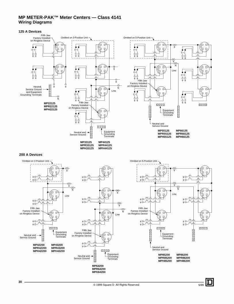
125 A DevicesFifth Jaw
Factory Installedon Ringless Device
N
Neutral,Service Groundand Equipment
Grounding Terminals
f
f
f
f
f f
MP22125MPR22125MPH22125
Omitted on 3-Position Unit Omitted on 5-Position Unit
MP33125MPR33125MPH33125
MP44125MPR44125MPH44125
MP55125MPR55125MPH55125
MP66125MPR66125MPH66125
NLine
EquipmentGroundingTerminals
Neutral andService Ground
N
Line
EquipmentGroundingTerminals
Neutral andService Ground
Fifth JawFactory Installed
on Ringless Device
Fifth JawFactory Installed
on Ringless Device
f f f f f ff f
f f
f f
f f
f f
f ff f
f ff f
MP64200MPR64200MPH64200
N
Line
EquipmentGroundingTerminals
Neutral andService Ground
ff
ff
ff
ff
f
f
f
fff
ff
ff
ff
ff
ff
f
f
ff
ff
f
f
Fifth JawFactory Installed
on Ringless Device
Fifth JawFactory Installed
on Ringless Device
Fifth JawFactory Installed
on Ringless Device
Omitted on 2-Position Unit Omitted on 5-Position Unit
MP42200MPR42200MPH42200
MP43200MPR43200MPH43200
MP85200MPR85200MPH85200
MP86200MPR86200MPH86200
NLine
EquipmentGroundingTerminals
Neutral andService Ground
N
Line
EquipmentGroundingTerminals
Neutral andService Ground
200 A Devices
MP METER-PAK™ Meter Centers — Class 4141Wiring Diagrams
315/99 © 1999 Square D All Rights Reserved
Application Data—EZ METER-PAK Meter Centers
EZ METER-PAK (EZM) Meter Centers Typical Equipment Lineups. . 32EZ METER-PAK Meter Centers . . . . . . . . . . . . . . . . . . . . . . . . . . . . . 33Main Device Ampere Ratings. . . . . . . . . . . . . . . . . . . . . . . . . . . . . . . 35Branch Units. . . . . . . . . . . . . . . . . . . . . . . . . . . . . . . . . . . . . . . . . . . . 36Horizontal Cross Bus . . . . . . . . . . . . . . . . . . . . . . . . . . . . . . . . . . . . . 44Factory Phase Balancing . . . . . . . . . . . . . . . . . . . . . . . . . . . . . . . . . . 58EZM Main Device Types and Configurations . . . . . . . . . . . . . . . . . . . 60
Selection . . . . . . . . . . . . . . . . . . . . . . . . . . . . . . . . . . . . . . . . . . . . . . . . . . 65
Dimensions and Knockouts . . . . . . . . . . . . . . . . . . . . . . . . . . . . . . . . . . 72
Wiring Diagrams . . . . . . . . . . . . . . . . . . . . . . . . . . . . . . . . . . . . . . . . . . . . 84
EZ METER-PAK® Meter Centers — Class 4161, 4162Contents
© 1999 Square D All Rights Reserved32
5/99
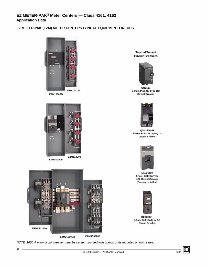
EZ METER-PAK (EZM) METER CENTERS TYPICAL EQUIPMENT LINEUPS
NOTE: 1600 A main circuit breaker must be center mounted with branch units mounted on both sides.
EZM114125
EZM1800CB
EZM1800TB
EZML312400
EZM31600CB EZMR333200
EZM114200
QO21002-Pole, Plug-On Type QO
Circuit Breaker
Q2M2200VH2-Pole, Bolt-On Type Q2M
Circuit Breaker
LAL364003-Pole, Bolt-On Type LAL Circuit Breaker(Factory Installed)
QE3200VH3-Pole, Bolt-On Type QE
Circuit Breaker
Typical TenantCircuit Breakers
EZ METER-PAK® Meter Centers — Class 4161, 4162Application Data
335/99 © 1999 Square D All Rights Reserved
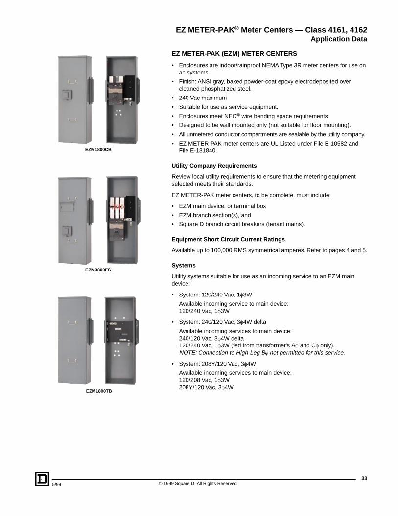
EZ METER-PAK (EZM) METER CENTERS
• Enclosures are indoor/rainproof NEMA Type 3R meter centers for use on ac systems.
• Finish: ANSI gray, baked powder-coat epoxy electrodeposited over cleaned phosphatized steel.
• 240 Vac maximum
• Suitable for use as service equipment.
• Enclosures meet NEC® wire bending space requirements
• Designed to be wall mounted only (not suitable for floor mounting).
• All unmetered conductor compartments are sealable by the utility company.
• EZ METER-PAK meter centers are UL Listed under File E-10582 and File E-131840.
Utility Company Requirements
Review local utility requirements to ensure that the metering equipment selected meets their standards.
EZ METER-PAK meter centers, to be complete, must include:
• EZM main device, or terminal box
• EZM branch section(s), and
• Square D branch circuit breakers (tenant mains).
Equipment Short Circuit Current Ratings
Available up to 100,000 RMS symmetrical amperes. Refer to pages 4 and 5.
Systems
Utility systems suitable for use as an incoming service to an EZM main device:
• System: 120/240 Vac, 1f3W
Available incoming service to main device:120/240 Vac, 1f3W
• System: 240/120 Vac, 3f4W delta
Available incoming services to main device: 240/120 Vac, 3f4W delta120/240 Vac, 1f3W (fed from transformer’s Af and Cf only).NOTE: Connection to High-Leg Bf not permitted for this service.
• System: 208Y/120 Vac, 3f4W
Available incoming services to main device: 120/208 Vac, 1f3W208Y/120 Vac, 3f4W
EZM1800CB
EZM3800FS
EZM1800TB
EZ METER-PAK® Meter Centers — Class 4161, 4162Application Data
© 1999 Square D All Rights Reserved34
5/99
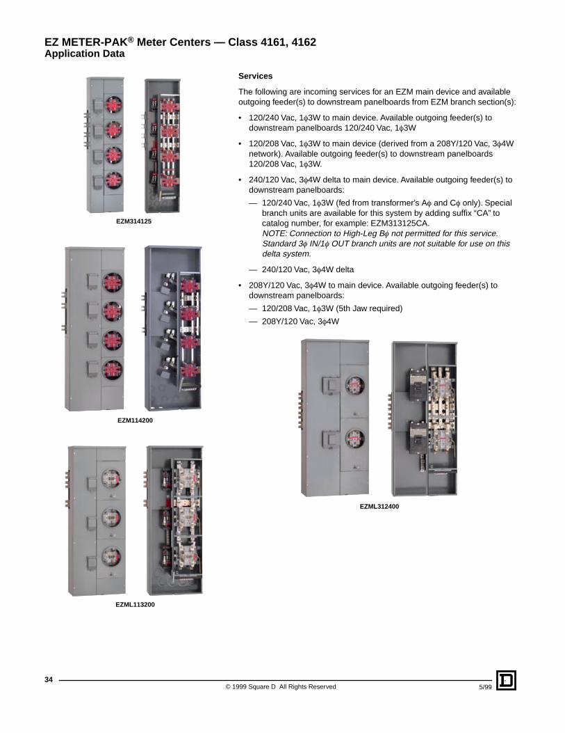
Services
The following are incoming services for an EZM main device and available outgoing feeder(s) to downstream panelboards from EZM branch section(s):
• 120/240 Vac, 1f3W to main device. Available outgoing feeder(s) to downstream panelboards 120/240 Vac, 1f3W
• 120/208 Vac, 1f3W to main device (derived from a 208Y/120 Vac, 3f4W network). Available outgoing feeder(s) to downstream panelboards 120/208 Vac, 1f3W.
• 240/120 Vac, 3f4W delta to main device. Available outgoing feeder(s) to downstream panelboards:
— 120/240 Vac, 1f3W (fed from transformer’s Af and Cf only). Special branch units are available for this system by adding suffix “CA” to catalog number, for example: EZM313125CA.NOTE: Connection to High-Leg Bf not permitted for this service.Standard 3f IN/1f OUT branch units are not suitable for use on this delta system.
— 240/120 Vac, 3f4W delta
• 208Y/120 Vac, 3f4W to main device. Available outgoing feeder(s) to downstream panelboards:
— 120/208 Vac, 1f3W (5th Jaw required)
— 208Y/120 Vac, 3f4W
EZML312400
EZM314125
EZM114200
EZML113200
EZ METER-PAK® Meter Centers — Class 4161, 4162Application Data
355/99 © 1999 Square D All Rights Reserved
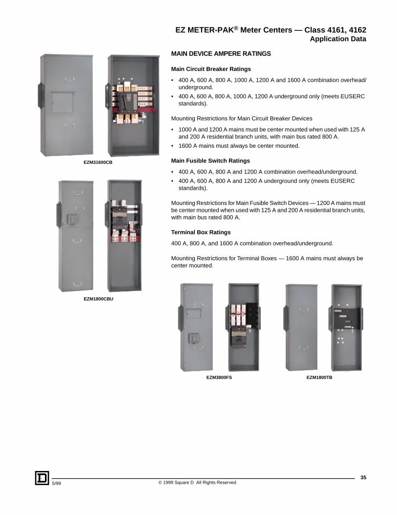
MAIN DEVICE AMPERE RATINGS
Main Circuit Breaker Ratings
• 400 A, 600 A, 800 A, 1000 A, 1200 A and 1600 A combination overhead/underground.
• 400 A, 600 A, 800 A, 1000 A, 1200 A underground only (meets EUSERC standards).
Mounting Restrictions for Main Circuit Breaker Devices
• 1000 A and 1200 A mains must be center mounted when used with 125 A and 200 A residential branch units, with main bus rated 800 A.
• 1600 A mains must always be center mounted.
Main Fusible Switch Ratings
• 400 A, 600 A, 800 A and 1200 A combination overhead/underground.
• 400 A, 600 A, 800 A and 1200 A underground only (meets EUSERC standards).
Mounting Restrictions for Main Fusible Switch Devices — 1200 A mains must be center mounted when used with 125 A and 200 A residential branch units, with main bus rated 800 A.
Terminal Box Ratings
400 A, 800 A, and 1600 A combination overhead/underground.
Mounting Restrictions for Terminal Boxes — 1600 A mains must always be center mounted.
EZM1800TBEZM3800FS
EZM31600CB
EZM1800CBU
EZ METER-PAK® Meter Centers — Class 4161, 4162Application Data
© 1999 Square D All Rights Reserved36
5/99
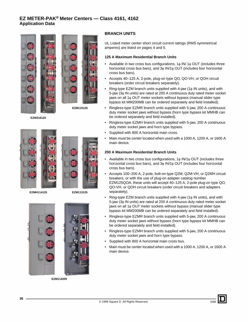
BRANCH UNITS
UL Listed meter center short circuit current ratings (RMS symmetrical amperes) are listed on pages 4 and 5.
125 A Maximum Residential Branch Units
• Available in two cross bus configurations, 1f IN/ 1f OUT (includes three horizontal cross bus bars), and 3f IN/1f OUT (includes four horizontal cross bus bars).
• Accepts 40–125 A, 2-pole, plug-on type QO, QO-VH, or QOH circuit breakers (order circuit breakers separately).
• Ring-type EZM branch units supplied with 4-jaw (1f IN units), and with 5-jaw (3f IN units) are rated at 200 A continuous duty rated meter socket jaws on all 1f OUT meter sockets without bypass (manual slider type bypass kit MM200MB can be ordered separately and field installed).
• Ringless-type EZMR branch units supplied with 5-jaw, 200 A continuous duty meter socket jaws without bypass (horn type bypass kit MMHB can be ordered separately and field installed).
• Ringless-type EZMH branch units supplied with 5-jaw, 200 A continuous duty meter socket jaws and horn type bypass.
• Supplied with 800 A horizontal main cross.
• Main must be center located when used with a 1000 A, 1200 A, or 1600 A main device.
200 A Maximum Residential Branch Units
• Available in two cross bus configurations, 1f IN/1f OUT (includes three horizontal cross bus bars), and 3f IN/1f OUT (includes four horizontal cross bus bars).
• Accepts 100–200 A, 2-pole, bolt-on type Q2M, Q2M-VH, or Q2MH circuit breakers, or with the use of plug-on adapter catalog number EZM125QOA, these units will accept 40–125 A, 2-pole plug-on type QO, QO-VH, or QOH circuit breakers (order circuit breakers and adapters separately).
• Ring-type EZM branch units supplied with 4-jaw (1f IN units), and with 5-jaw (3f IN units) are rated at 200 A continuous duty rated meter socket jaws on all 1f OUT meter sockets without bypass (manual slider type bypass kit MM200MB can be ordered separately and field installed).
• Ringless-type EZMR branch units supplied with 5-jaw, 200 A continuous duty meter socket jaws without bypass (horn type bypass kit MMHB can be ordered separately and field installed).
• Ringless-type EZMH branch units supplied with 5-jaw, 200 A continuous duty meter socket jaws and horn type bypass.
• Supplied with 800 A horizontal main cross bus.
• Main must be center located when used with a 1000 A, 1200 A, or 1600 A main device.
EZM115125
EZM316125
EZM113125
EZ METER-PAK® Meter Centers — Class 4161, 4162Application Data
EZM114200
EZMH114125
375/99 © 1999 Square D All Rights Reserved
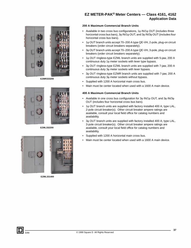
200 A Maximum Commercial Branch Units
• Available in two cross bus configurations, 1f IN/1f OUT (includes three horizontal cross bus bars), 3f IN/1f OUT, and 3f IN/3f OUT (includes four horizontal cross bus bars).
• 1f OUT branch units accept 70–200 A type QE-VH, 2-pole, plug-on circuit breakers (order circuit breakers separately).
• 3f OUT branch units accept 70–200 A type QE-VH, 3-pole, plug-on circuit breakers (order circuit breakers separately).
• 1f OUT ringless-type EZML branch units are supplied with 5-jaw, 200 A continuous duty 1f meter sockets with lever type bypass.
• 3f OUT ringless-type EZML branch units are supplied with 7-jaw, 200 A continuous duty 3f meter sockets with lever bypass.
• 3f OUT ringless-type EZMR branch units are supplied with 7-jaw, 200 A continuous duty 3f meter sockets without bypass.
• Supplied with 1200 A horizontal main cross bus.
• Main must be center located when used with a 1600 A main device.
400 A Maximum Commercial Branch Units
• Available in one cross bus configuration for 3f IN/1f OUT, and 3f IN/3f OUT (includes four horizontal cross bus bars).
• 1f OUT branch units are supplied with factory installed 400 A, type LAL, 2-pole circuit breaker(s). Other circuit breaker ampere ratings are available, consult your local field office for catalog numbers and availability.
• 3f OUT branch units are supplied with factory installed 400 A, type LAL, 3-pole circuit breaker(s). Other circuit breaker ampere ratings are available, consult your local field office for catalog numbers and availability.
• Supplied with 1200 A horizontal main cross bus.
• Main must be center located when used with a 1600 A main device.
EZMR333200
EZML332200
EZML331400
EZ METER-PAK® Meter Centers — Class 4161, 4162Application Data
© 1999 Square D All Rights Reserved38
5/99
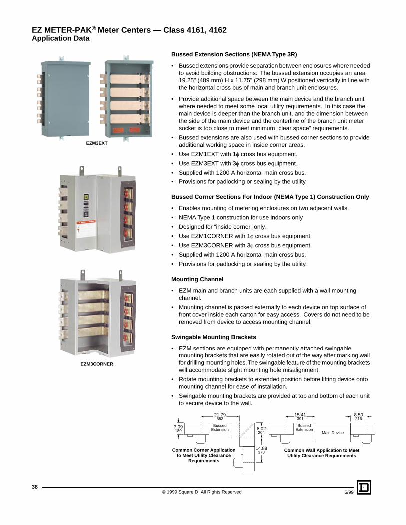
Bussed Extension Sections (NEMA Type 3R)
• Bussed extensions provide separation between enclosures where needed to avoid building obstructions. The bussed extension occupies an area 19.25" (489 mm) H x 11.75" (298 mm) W positioned vertically in line with the horizontal cross bus of main and branch unit enclosures.
• Provide additional space between the main device and the branch unit where needed to meet some local utility requirements. In this case the main device is deeper than the branch unit, and the dimension between the side of the main device and the centerline of the branch unit meter socket is too close to meet minimum “clear space” requirements.
• Bussed extensions are also used with bussed corner sections to provide additional working space in inside corner areas.
• Use EZM1EXT with 1f cross bus equipment.
• Use EZM3EXT with 3f cross bus equipment.
• Supplied with 1200 A horizontal main cross bus.
• Provisions for padlocking or sealing by the utility.
Bussed Corner Sections For Indoor (NEMA Type 1) Construction Only
• Enables mounting of metering enclosures on two adjacent walls.
• NEMA Type 1 construction for use indoors only.
• Designed for “inside corner” only.
• Use EZM1CORNER with 1f cross bus equipment.
• Use EZM3CORNER with 3f cross bus equipment.
• Supplied with 1200 A horizontal main cross bus.
• Provisions for padlocking or sealing by the utility.
Mounting Channel
• EZM main and branch units are each supplied with a wall mounting channel.
• Mounting channel is packed externally to each device on top surface of front cover inside each carton for easy access. Covers do not need to be removed from device to access mounting channel.
Swingable Mounting Brackets
• EZM sections are equipped with permanently attached swingable mounting brackets that are easily rotated out of the way after marking wall for drilling mounting holes. The swingable feature of the mounting brackets will accommodate slight mounting hole misalignment.
• Rotate mounting brackets to extended position before lifting device onto mounting channel for ease of installation.
• Swingable mounting brackets are provided at top and bottom of each unit to secure device to the wall.
BussedExtension
21.79553
BussedExtension
15.41391
8.50216
7.09180 8.02
204
14.88378Common Corner Application
to Meet Utility ClearanceRequirements
Common Wall Application to MeetUtility Clearance Requirements
Main Device
EZ METER-PAK® Meter Centers — Class 4161, 4162Application Data
EZM3EXT
EZM3CORNER
395/99 © 1999 Square D All Rights Reserved
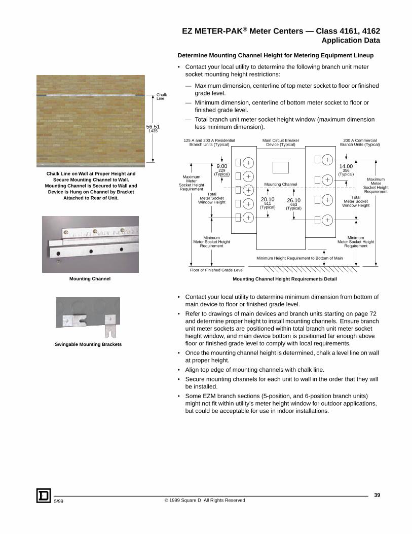
Chalk Line on Wall at Proper Height and Secure Mounting Channel to Wall.
Mounting Channel is Secured to Wall and Device is Hung on Channel by Bracket
Attached to Rear of Unit.
Mounting Channel
Swingable Mounting Brackets
56.511435
ChalkLine
Determine Mounting Channel Height for Metering Equipment Lineup
• Contact your local utility to determine the following branch unit meter socket mounting height restrictions:
— Maximum dimension, centerline of top meter socket to floor or finished grade level.
— Minimum dimension, centerline of bottom meter socket to floor or finished grade level.
— Total branch unit meter socket height window (maximum dimension less minimum dimension).
• Contact your local utility to determine minimum dimension from bottom of main device to floor or finished grade level.
• Refer to drawings of main devices and branch units starting on page 72 and determine proper height to install mounting channels. Ensure branch unit meter sockets are positioned within total branch unit meter socket height window, and main device bottom is positioned far enough above floor or finished grade level to comply with local requirements.
• Once the mounting channel height is determined, chalk a level line on wall at proper height.
• Align top edge of mounting channels with chalk line.
• Secure mounting channels for each unit to wall in the order that they will be installed.
• Some EZM branch sections (5-position, and 6-position branch units) might not fit within utility's meter height window for outdoor applications, but could be acceptable for use in indoor installations.
14.00356
(Typical)
9.00229
(Typical)
26.10663
(Typical)
20.10511
(Typical)
TotalMeter Socket
Window Height
TotalMeter Socket
Window Height
MinimumMeter Socket Height
Requirement
MinimumMeter Socket Height
Requirement
MaximumMeter
Socket HeightRequirement
MaximumMeter
Socket HeightRequirement
200 A CommercialBranch Units (Typical)
125 A and 200 A ResidentialBranch Units (Typical)
Main Circuit BreakerDevice (Typical)
Mounting Channel
Minimum Height Requirement to Bottom of Main
Floor or Finished Grade Level
Mounting Channel Height Requirements Detail
EZ METER-PAK® Meter Centers — Class 4161, 4162Application Data
© 1999 Square D All Rights Reserved40
5/99
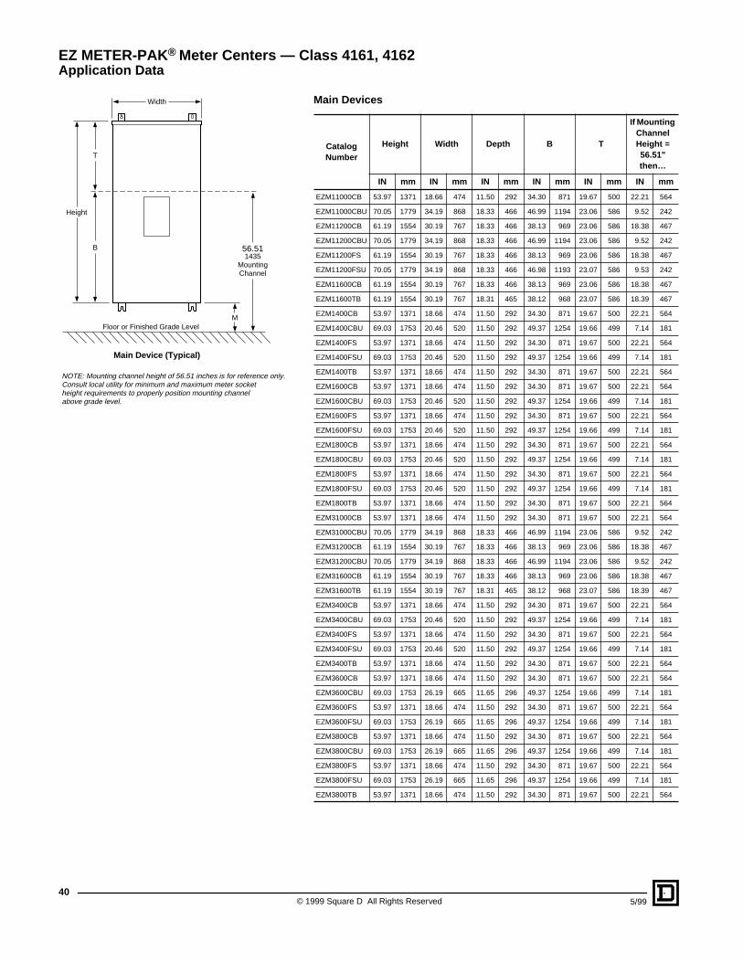
Main Devices
Catalog Number
Height Width Depth B T
If Mounting Channel Height = 56.51" then…
IN mm IN mm IN mm IN mm IN mm IN mm
EZM11000CB 53.97 1371 18.66 474 11.50 292 34.30 871 19.67 500 22.21 564
EZM11000CBU 70.05 1779 34.19 868 18.33 466 46.99 1194 23.06 586 9.52 242
EZM11200CB 61.19 1554 30.19 767 18.33 466 38.13 969 23.06 586 18.38 467
EZM11200CBU 70.05 1779 34.19 868 18.33 466 46.99 1194 23.06 586 9.52 242
EZM11200FS 61.19 1554 30.19 767 18.33 466 38.13 969 23.06 586 18.38 467
EZM11200FSU 70.05 1779 34.19 868 18.33 466 46.98 1193 23.07 586 9.53 242
EZM11600CB 61.19 1554 30.19 767 18.33 466 38.13 969 23.06 586 18.38 467
EZM11600TB 61.19 1554 30.19 767 18.31 465 38.12 968 23.07 586 18.39 467
EZM1400CB 53.97 1371 18.66 474 11.50 292 34.30 871 19.67 500 22.21 564
EZM1400CBU 69.03 1753 20.46 520 11.50 292 49.37 1254 19.66 499 7.14 181
EZM1400FS 53.97 1371 18.66 474 11.50 292 34.30 871 19.67 500 22.21 564
EZM1400FSU 69.03 1753 20.46 520 11.50 292 49.37 1254 19.66 499 7.14 181
EZM1400TB 53.97 1371 18.66 474 11.50 292 34.30 871 19.67 500 22.21 564
EZM1600CB 53.97 1371 18.66 474 11.50 292 34.30 871 19.67 500 22.21 564
EZM1600CBU 69.03 1753 20.46 520 11.50 292 49.37 1254 19.66 499 7.14 181
EZM1600FS 53.97 1371 18.66 474 11.50 292 34.30 871 19.67 500 22.21 564
EZM1600FSU 69.03 1753 20.46 520 11.50 292 49.37 1254 19.66 499 7.14 181
EZM1800CB 53.97 1371 18.66 474 11.50 292 34.30 871 19.67 500 22.21 564
EZM1800CBU 69.03 1753 20.46 520 11.50 292 49.37 1254 19.66 499 7.14 181
EZM1800FS 53.97 1371 18.66 474 11.50 292 34.30 871 19.67 500 22.21 564
EZM1800FSU 69.03 1753 20.46 520 11.50 292 49.37 1254 19.66 499 7.14 181
EZM1800TB 53.97 1371 18.66 474 11.50 292 34.30 871 19.67 500 22.21 564
EZM31000CB 53.97 1371 18.66 474 11.50 292 34.30 871 19.67 500 22.21 564
EZM31000CBU 70.05 1779 34.19 868 18.33 466 46.99 1194 23.06 586 9.52 242
EZM31200CB 61.19 1554 30.19 767 18.33 466 38.13 969 23.06 586 18.38 467
EZM31200CBU 70.05 1779 34.19 868 18.33 466 46.99 1194 23.06 586 9.52 242
EZM31600CB 61.19 1554 30.19 767 18.33 466 38.13 969 23.06 586 18.38 467
EZM31600TB 61.19 1554 30.19 767 18.31 465 38.12 968 23.07 586 18.39 467
EZM3400CB 53.97 1371 18.66 474 11.50 292 34.30 871 19.67 500 22.21 564
EZM3400CBU 69.03 1753 20.46 520 11.50 292 49.37 1254 19.66 499 7.14 181
EZM3400FS 53.97 1371 18.66 474 11.50 292 34.30 871 19.67 500 22.21 564
EZM3400FSU 69.03 1753 20.46 520 11.50 292 49.37 1254 19.66 499 7.14 181
EZM3400TB 53.97 1371 18.66 474 11.50 292 34.30 871 19.67 500 22.21 564
EZM3600CB 53.97 1371 18.66 474 11.50 292 34.30 871 19.67 500 22.21 564
EZM3600CBU 69.03 1753 26.19 665 11.65 296 49.37 1254 19.66 499 7.14 181
EZM3600FS 53.97 1371 18.66 474 11.50 292 34.30 871 19.67 500 22.21 564
EZM3600FSU 69.03 1753 26.19 665 11.65 296 49.37 1254 19.66 499 7.14 181
EZM3800CB 53.97 1371 18.66 474 11.50 292 34.30 871 19.67 500 22.21 564
EZM3800CBU 69.03 1753 26.19 665 11.65 296 49.37 1254 19.66 499 7.14 181
EZM3800FS 53.97 1371 18.66 474 11.50 292 34.30 871 19.67 500 22.21 564
EZM3800FSU 69.03 1753 26.19 665 11.65 296 49.37 1254 19.66 499 7.14 181
EZM3800TB 53.97 1371 18.66 474 11.50 292 34.30 871 19.67 500 22.21 564
MFloor or Finished Grade Level
Height
Width
56.511435
MountingChannel
T
B
NOTE: Mounting channel height of 56.51 inches is for reference only.Consult local utility for minimum and maximum meter socketheight requirements to properly position mounting channelabove grade level.
Main Device (Typical)
EZ METER-PAK® Meter Centers — Class 4161, 4162Application Data
415/99 © 1999 Square D All Rights Reserved
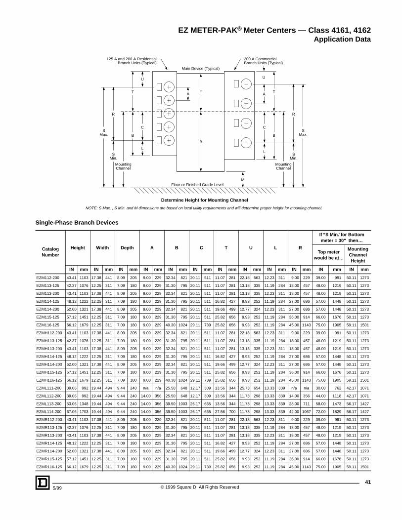
Single-Phase Branch Devices
Catalog Number
Height Width Depth A B C T U L R
If “S Min.’ for Bottom meter = 30" then…
Top meterwould be at…
Mounting Channel Height
IN mm IN mm IN mm IN mm IN mm IN mm IN mm IN mm IN mm IN mm IN mm IN mm
EZM112-200 43.41 1103 17.38 441 8.09 205 9.00 229 32.34 821 20.11 511 11.07 281 22.18 563 12.23 311 9.00 229 39.00 991 50.11 1273
EZM113-125 42.37 1076 12.25 311 7.09 180 9.00 229 31.30 795 20.11 511 11.07 281 13.18 335 11.19 284 18.00 457 48.00 1219 50.11 1273
EZM113-200 43.41 1103 17.38 441 8.09 205 9.00 229 32.34 821 20.11 511 11.07 281 13.18 335 12.23 311 18.00 457 48.00 1219 50.11 1273
EZM114-125 48.12 1222 12.25 311 7.09 180 9.00 229 31.30 795 20.11 511 16.82 427 9.93 252 11.19 284 27.00 686 57.00 1448 50.11 1273
EZM114-200 52.00 1321 17.38 441 8.09 205 9.00 229 32.34 821 20.11 511 19.66 499 12.77 324 12.23 311 27.00 686 57.00 1448 50.11 1273
EZM115-125 57.12 1451 12.25 311 7.09 180 9.00 229 31.30 795 20.11 511 25.82 656 9.93 252 11.19 284 36.00 914 66.00 1676 50.11 1273
EZM116-125 66.12 1679 12.25 311 7.09 180 9.00 229 40.30 1024 29.11 739 25.82 656 9.93 252 11.19 284 45.00 1143 75.00 1905 59.11 1501
EZMH112-200 43.41 1103 17.38 441 8.09 205 9.00 229 32.34 821 20.11 511 11.07 281 22.18 563 12.23 311 9.00 229 39.00 991 50.11 1273
EZMH113-125 42.37 1076 12.25 311 7.09 180 9.00 229 31.30 795 20.11 511 11.07 281 13.18 335 11.19 284 18.00 457 48.00 1219 50.11 1273
EZMH113-200 43.41 1103 17.38 441 8.09 205 9.00 229 32.34 821 20.11 511 11.07 281 13.18 335 12.23 311 18.00 457 48.00 1219 50.11 1273
EZMH114-125 48.12 1222 12.25 311 7.09 180 9.00 229 31.30 795 20.11 511 16.82 427 9.93 252 11.19 284 27.00 686 57.00 1448 50.11 1273
EZMH114-200 52.00 1321 17.38 441 8.09 205 9.00 229 32.34 821 20.11 511 19.66 499 12.77 324 12.23 311 27.00 686 57.00 1448 50.11 1273
EZMH115-125 57.12 1451 12.25 311 7.09 180 9.00 229 31.30 795 20.11 511 25.82 656 9.93 252 11.19 284 36.00 914 66.00 1676 50.11 1273
EZMH116-125 66.12 1679 12.25 311 7.09 180 9.00 229 40.30 1024 29.11 739 25.82 656 9.93 252 11.19 284 45.00 1143 75.00 1905 59.11 1501
EZML111-200 39.06 992 19.44 494 9.44 240 n/a n/a 25.50 648 12.17 309 13.56 344 25.73 654 13.33 339 n/a n/a 30.00 762 42.17 1071
EZML112-200 39.06 992 19.44 494 9.44 240 14.00 356 25.50 648 12.17 309 13.56 344 11.73 298 13.33 339 14.00 356 44.00 1118 42.17 1071
EZML113-200 53.06 1348 19.44 494 9.44 240 14.00 356 39.50 1003 26.17 665 13.56 344 11.73 298 13.33 339 28.00 711 58.00 1473 56.17 1427
EZML114-200 67.06 1703 19.44 494 9.44 240 14.00 356 39.50 1003 26.17 665 27.56 700 11.73 298 13.33 339 42.00 1067 72.00 1829 56.17 1427
EZMR112-200 43.41 1103 17.38 441 8.09 205 9.00 229 32.34 821 20.11 511 11.07 281 22.18 563 12.23 311 9.00 229 39.00 991 50.11 1273
EZMR113-125 42.37 1076 12.25 311 7.09 180 9.00 229 31.30 795 20.11 511 11.07 281 13.18 335 11.19 284 18.00 457 48.00 1219 50.11 1273
EZMR113-200 43.41 1103 17.38 441 8.09 205 9.00 229 32.34 821 20.11 511 11.07 281 13.18 335 12.23 311 18.00 457 48.00 1219 50.11 1273
EZMR114-125 48.12 1222 12.25 311 7.09 180 9.00 229 31.30 795 20.11 511 16.82 427 9.93 252 11.19 284 27.00 686 57.00 1448 50.11 1273
EZMR114-200 52.00 1321 17.38 441 8.09 205 9.00 229 32.34 821 20.11 511 19.66 499 12.77 324 12.23 311 27.00 686 57.00 1448 50.11 1273
EZMR115-125 57.12 1451 12.25 311 7.09 180 9.00 229 31.30 795 20.11 511 25.82 656 9.93 252 11.19 284 36.00 914 66.00 1676 50.11 1273
EZMR116-125 66.12 1679 12.25 311 7.09 180 9.00 229 40.30 1024 29.11 739 25.82 656 9.93 252 11.19 284 45.00 1143 75.00 1905 59.11 1501
200 A CommercialBranch Units (Typical)
125 A and 200 A ResidentialBranch Units (Typical)
Main Device (Typical)
MFloor or Finished Grade Level
Determine Height for Mounting Channel
A A T
B
T
B
R
SMin.
R
SMin.
MountingChannel
MountingChannel
C
L
C
L
UU
T
B
SMax.
SMax.
NOTE: S Max. , S Min. and M dimensions are based on local utility requirements and will determine proper height for mounting channel.
EZ METER-PAK® Meter Centers — Class 4161, 4162Application Data
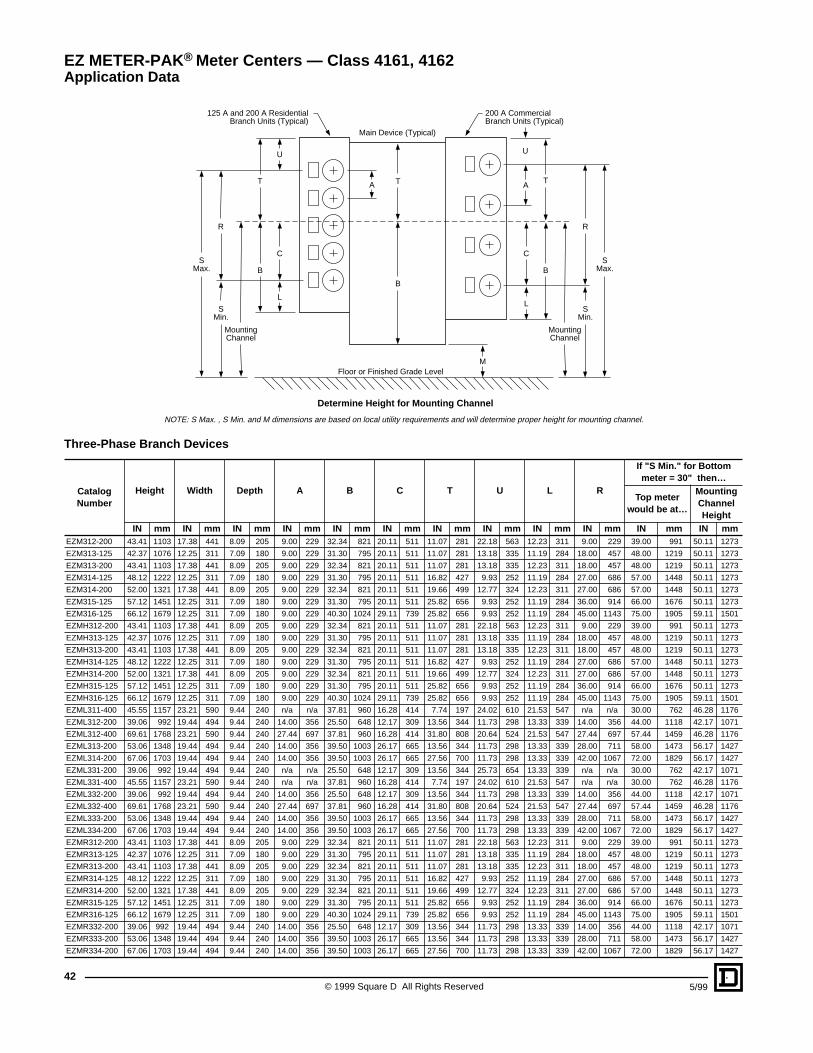
© 1999 Square D All Rights Reserved42
5/99
Three-Phase Branch Devices
Catalog Number
Height Width Depth A B C T U L R
If "S Min." for Bottom meter = 30" then…
Top meter would be at…
Mounting Channel Height
IN mm IN mm IN mm IN mm IN mm IN mm IN mm IN mm IN mm IN mm IN mm IN mmEZM312-200 43.41 1103 17.38 441 8.09 205 9.00 229 32.34 821 20.11 511 11.07 281 22.18 563 12.23 311 9.00 229 39.00 991 50.11 1273
EZM313-125 42.37 1076 12.25 311 7.09 180 9.00 229 31.30 795 20.11 511 11.07 281 13.18 335 11.19 284 18.00 457 48.00 1219 50.11 1273
EZM313-200 43.41 1103 17.38 441 8.09 205 9.00 229 32.34 821 20.11 511 11.07 281 13.18 335 12.23 311 18.00 457 48.00 1219 50.11 1273
EZM314-125 48.12 1222 12.25 311 7.09 180 9.00 229 31.30 795 20.11 511 16.82 427 9.93 252 11.19 284 27.00 686 57.00 1448 50.11 1273
EZM314-200 52.00 1321 17.38 441 8.09 205 9.00 229 32.34 821 20.11 511 19.66 499 12.77 324 12.23 311 27.00 686 57.00 1448 50.11 1273
EZM315-125 57.12 1451 12.25 311 7.09 180 9.00 229 31.30 795 20.11 511 25.82 656 9.93 252 11.19 284 36.00 914 66.00 1676 50.11 1273
EZM316-125 66.12 1679 12.25 311 7.09 180 9.00 229 40.30 1024 29.11 739 25.82 656 9.93 252 11.19 284 45.00 1143 75.00 1905 59.11 1501
EZMH312-200 43.41 1103 17.38 441 8.09 205 9.00 229 32.34 821 20.11 511 11.07 281 22.18 563 12.23 311 9.00 229 39.00 991 50.11 1273
EZMH313-125 42.37 1076 12.25 311 7.09 180 9.00 229 31.30 795 20.11 511 11.07 281 13.18 335 11.19 284 18.00 457 48.00 1219 50.11 1273
EZMH313-200 43.41 1103 17.38 441 8.09 205 9.00 229 32.34 821 20.11 511 11.07 281 13.18 335 12.23 311 18.00 457 48.00 1219 50.11 1273
EZMH314-125 48.12 1222 12.25 311 7.09 180 9.00 229 31.30 795 20.11 511 16.82 427 9.93 252 11.19 284 27.00 686 57.00 1448 50.11 1273
EZMH314-200 52.00 1321 17.38 441 8.09 205 9.00 229 32.34 821 20.11 511 19.66 499 12.77 324 12.23 311 27.00 686 57.00 1448 50.11 1273
EZMH315-125 57.12 1451 12.25 311 7.09 180 9.00 229 31.30 795 20.11 511 25.82 656 9.93 252 11.19 284 36.00 914 66.00 1676 50.11 1273
EZMH316-125 66.12 1679 12.25 311 7.09 180 9.00 229 40.30 1024 29.11 739 25.82 656 9.93 252 11.19 284 45.00 1143 75.00 1905 59.11 1501
EZML311-400 45.55 1157 23.21 590 9.44 240 n/a n/a 37.81 960 16.28 414 7.74 197 24.02 610 21.53 547 n/a n/a 30.00 762 46.28 1176
EZML312-200 39.06 992 19.44 494 9.44 240 14.00 356 25.50 648 12.17 309 13.56 344 11.73 298 13.33 339 14.00 356 44.00 1118 42.17 1071
EZML312-400 69.61 1768 23.21 590 9.44 240 27.44 697 37.81 960 16.28 414 31.80 808 20.64 524 21.53 547 27.44 697 57.44 1459 46.28 1176
EZML313-200 53.06 1348 19.44 494 9.44 240 14.00 356 39.50 1003 26.17 665 13.56 344 11.73 298 13.33 339 28.00 711 58.00 1473 56.17 1427
EZML314-200 67.06 1703 19.44 494 9.44 240 14.00 356 39.50 1003 26.17 665 27.56 700 11.73 298 13.33 339 42.00 1067 72.00 1829 56.17 1427
EZML331-200 39.06 992 19.44 494 9.44 240 n/a n/a 25.50 648 12.17 309 13.56 344 25.73 654 13.33 339 n/a n/a 30.00 762 42.17 1071
EZML331-400 45.55 1157 23.21 590 9.44 240 n/a n/a 37.81 960 16.28 414 7.74 197 24.02 610 21.53 547 n/a n/a 30.00 762 46.28 1176
EZML332-200 39.06 992 19.44 494 9.44 240 14.00 356 25.50 648 12.17 309 13.56 344 11.73 298 13.33 339 14.00 356 44.00 1118 42.17 1071
EZML332-400 69.61 1768 23.21 590 9.44 240 27.44 697 37.81 960 16.28 414 31.80 808 20.64 524 21.53 547 27.44 697 57.44 1459 46.28 1176
EZML333-200 53.06 1348 19.44 494 9.44 240 14.00 356 39.50 1003 26.17 665 13.56 344 11.73 298 13.33 339 28.00 711 58.00 1473 56.17 1427
EZML334-200 67.06 1703 19.44 494 9.44 240 14.00 356 39.50 1003 26.17 665 27.56 700 11.73 298 13.33 339 42.00 1067 72.00 1829 56.17 1427
EZMR312-200 43.41 1103 17.38 441 8.09 205 9.00 229 32.34 821 20.11 511 11.07 281 22.18 563 12.23 311 9.00 229 39.00 991 50.11 1273
EZMR313-125 42.37 1076 12.25 311 7.09 180 9.00 229 31.30 795 20.11 511 11.07 281 13.18 335 11.19 284 18.00 457 48.00 1219 50.11 1273
EZMR313-200 43.41 1103 17.38 441 8.09 205 9.00 229 32.34 821 20.11 511 11.07 281 13.18 335 12.23 311 18.00 457 48.00 1219 50.11 1273
EZMR314-125 48.12 1222 12.25 311 7.09 180 9.00 229 31.30 795 20.11 511 16.82 427 9.93 252 11.19 284 27.00 686 57.00 1448 50.11 1273
EZMR314-200 52.00 1321 17.38 441 8.09 205 9.00 229 32.34 821 20.11 511 19.66 499 12.77 324 12.23 311 27.00 686 57.00 1448 50.11 1273
EZMR315-125 57.12 1451 12.25 311 7.09 180 9.00 229 31.30 795 20.11 511 25.82 656 9.93 252 11.19 284 36.00 914 66.00 1676 50.11 1273
EZMR316-125 66.12 1679 12.25 311 7.09 180 9.00 229 40.30 1024 29.11 739 25.82 656 9.93 252 11.19 284 45.00 1143 75.00 1905 59.11 1501
EZMR332-200 39.06 992 19.44 494 9.44 240 14.00 356 25.50 648 12.17 309 13.56 344 11.73 298 13.33 339 14.00 356 44.00 1118 42.17 1071
EZMR333-200 53.06 1348 19.44 494 9.44 240 14.00 356 39.50 1003 26.17 665 13.56 344 11.73 298 13.33 339 28.00 711 58.00 1473 56.17 1427
EZMR334-200 67.06 1703 19.44 494 9.44 240 14.00 356 39.50 1003 26.17 665 27.56 700 11.73 298 13.33 339 42.00 1067 72.00 1829 56.17 1427
200 A CommercialBranch Units (Typical)
125 A and 200 A ResidentialBranch Units (Typical)
Main Device (Typical)
MFloor or Finished Grade Level
Determine Height for Mounting Channel
A A T
B
T
B
R
SMin.
R
SMin.
MountingChannel
MountingChannel
C
L
C
L
UU
T
B
SMax.
SMax.
NOTE: S Max. , S Min. and M dimensions are based on local utility requirements and will determine proper height for mounting channel.
EZ METER-PAK® Meter Centers — Class 4161, 4162Application Data
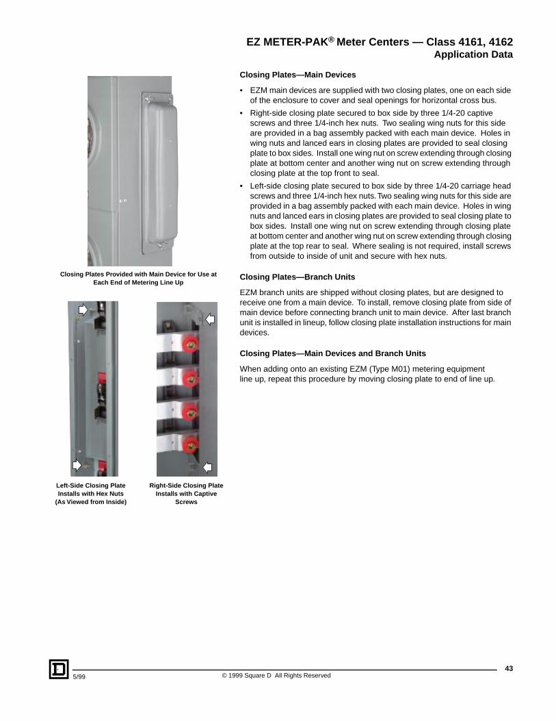
435/99 © 1999 Square D All Rights Reserved
Closing Plates—Main Devices
• EZM main devices are supplied with two closing plates, one on each side of the enclosure to cover and seal openings for horizontal cross bus.
• Right-side closing plate secured to box side by three 1/4-20 captive screws and three 1/4-inch hex nuts. Two sealing wing nuts for this side are provided in a bag assembly packed with each main device. Holes in wing nuts and lanced ears in closing plates are provided to seal closing plate to box sides. Install one wing nut on screw extending through closing plate at bottom center and another wing nut on screw extending through closing plate at the top front to seal.
• Left-side closing plate secured to box side by three 1/4-20 carriage head screws and three 1/4-inch hex nuts. Two sealing wing nuts for this side are provided in a bag assembly packed with each main device. Holes in wing nuts and lanced ears in closing plates are provided to seal closing plate to box sides. Install one wing nut on screw extending through closing plate at bottom center and another wing nut on screw extending through closing plate at the top rear to seal. Where sealing is not required, install screws from outside to inside of unit and secure with hex nuts.
Closing Plates—Branch Units
EZM branch units are shipped without closing plates, but are designed to receive one from a main device. To install, remove closing plate from side of main device before connecting branch unit to main device. After last branch unit is installed in lineup, follow closing plate installation instructions for main devices.
Closing Plates—Main Devices and Branch Units
When adding onto an existing EZM (Type M01) metering equipment line up, repeat this procedure by moving closing plate to end of line up.
EZ METER-PAK® Meter Centers — Class 4161, 4162Application Data
Closing Plates Provided with Main Device for Use at Each End of Metering Line Up
Left-Side Closing Plate Installs with Hex Nuts
(As Viewed from Inside)
Right-Side Closing Plate Installs with Captive
Screws
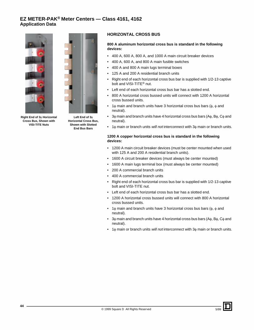
© 1999 Square D All Rights Reserved44
5/99
HORIZONTAL CROSS BUS
800 A aluminum horizontal cross bus is standard in the following devices:
• 400 A, 600 A, 800 A, and 1000 A main circuit breaker devices
• 400 A, 600 A, and 800 A main fusible switches
• 400 A and 800 A main lugs terminal boxes
• 125 A and 200 A residential branch units
• Right end of each horizontal cross bus bar is supplied with 1/2-13 captive bolt and VISI-TITE® nut.
• Left end of each horizontal cross bus bar has a slotted end.
• 800 A horizontal cross bussed units will connect with 1200 A horizontal cross bussed units.
• 1f main and branch units have 3 horizontal cross bus bars (f, f and neutral).
• 3f main and branch units have 4 horizontal cross bus bars (Af, Bf, Cf and neutral).
• 1f main or branch units will not interconnect with 3f main or branch units.
1200 A copper horizontal cross bus is standard in the following devices:
• 1200 A main circuit breaker devices (must be center mounted when used with 125 A and 200 A residential branch units).
• 1600 A circuit breaker devices (must always be center mounted)
• 1600 A main lugs terminal box (must always be center mounted)
• 200 A commercial branch units
• 400 A commercial branch units
• Right end of each horizontal cross bus bar is supplied with 1/2-13 captive bolt and VISI-TITE nut.
• Left end of each horizontal cross bus bar has a slotted end.
• 1200 A horizontal cross bussed units will connect with 800 A horizontal cross bussed units.
• 1f main and branch units have 3 horizontal cross bus bars (f, f and neutral).
• 3f main and branch units have 4 horizontal cross bus bars (Af, Bf, Cf and neutral).
• 1f main or branch units will not interconnect with 3f main or branch units.
EZ METER-PAK® Meter Centers — Class 4161, 4162Application Data
Right End of 3 f Horizontal Cross Bus, Shown with
VISI-TITE Nuts
Left End of 3 f Horizontal Cross Bus,
Shown with Slotted End Bus Bars
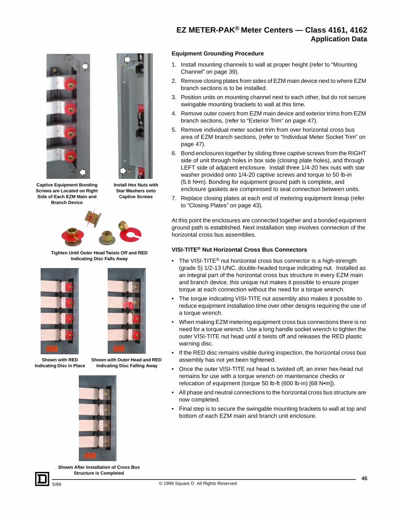
455/99 © 1999 Square D All Rights Reserved
Captive Equipment Bonding Screws are Located on Right Side of Each EZM Main and
Branch Device
Install Hex Nuts with Star Washers onto
Captive Screws
Tighten Until Outer Head Twists Off and RED Indicating Disc Falls Away
Shown with RED Indicating Disc in Place
Shown with Outer Head and RED Indicating Disc Falling Away
Shown After Installation of Cross Bus Structure is Completed
Equipment Grounding Procedure
1. Install mounting channels to wall at proper height (refer to “Mounting Channel” on page 39).
2. Remove closing plates from sides of EZM main device next to where EZM branch sections is to be installed.
3. Position units on mounting channel next to each other, but do not secure swingable mounting brackets to wall at this time.
4. Remove outer covers from EZM main device and exterior trims from EZM branch sections, (refer to “Exterior Trim” on page 47).
5. Remove individual meter socket trim from over horizontal cross bus area of EZM branch sections, (refer to “Individual Meter Socket Trim” on page 47).
6. Bond enclosures together by sliding three captive screws from the RIGHT side of unit through holes in box side (closing plate holes), and through LEFT side of adjacent enclosure. Install three 1/4-20 hex nuts with star washer provided onto 1/4-20 captive screws and torque to 50 lb-in(5.6 N•m). Bonding for equipment ground path is complete, and enclosure gaskets are compressed to seal connection between units.
7. Replace closing plates at each end of metering equipment lineup (refer to “Closing Plates” on page 43).
At this point the enclosures are connected together and a bonded equipment ground path is established. Next installation step involves connection of the horizontal cross bus assemblies.
VISI-TITE® Nut Horizontal Cross Bus Connectors
• The VISI-TITE® nut horizontal cross bus connector is a high-strength (grade 5) 1/2-13 UNC, double-headed torque indicating nut. Installed as an integral part of the horizontal cross bus structure in every EZM main and branch device, this unique nut makes it possible to ensure proper torque at each connection without the need for a torque wrench.
• The torque indicating VISI-TITE nut assembly also makes it possible to reduce equipment installation time over other designs requiring the use of a torque wrench.
• When making EZM metering equipment cross bus connections there is no need for a torque wrench. Use a long handle socket wrench to tighten the outer VISI-TITE nut head until it twists off and releases the RED plastic warning disc.
• If the RED disc remains visible during inspection, the horizontal cross bus assembly has not yet been tightened.
• Once the outer VISI-TITE nut head is twisted off, an inner hex-head nut remains for use with a torque wrench on maintenance checks or relocation of equipment (torque 50 lb-ft (600 lb-in) [68 N•m]).
• All phase and neutral connections to the horizontal cross bus structure are now completed.
• Final step is to secure the swingable mounting brackets to wall at top and bottom of each EZM main and branch unit enclosure.
EZ METER-PAK® Meter Centers — Class 4161, 4162Application Data
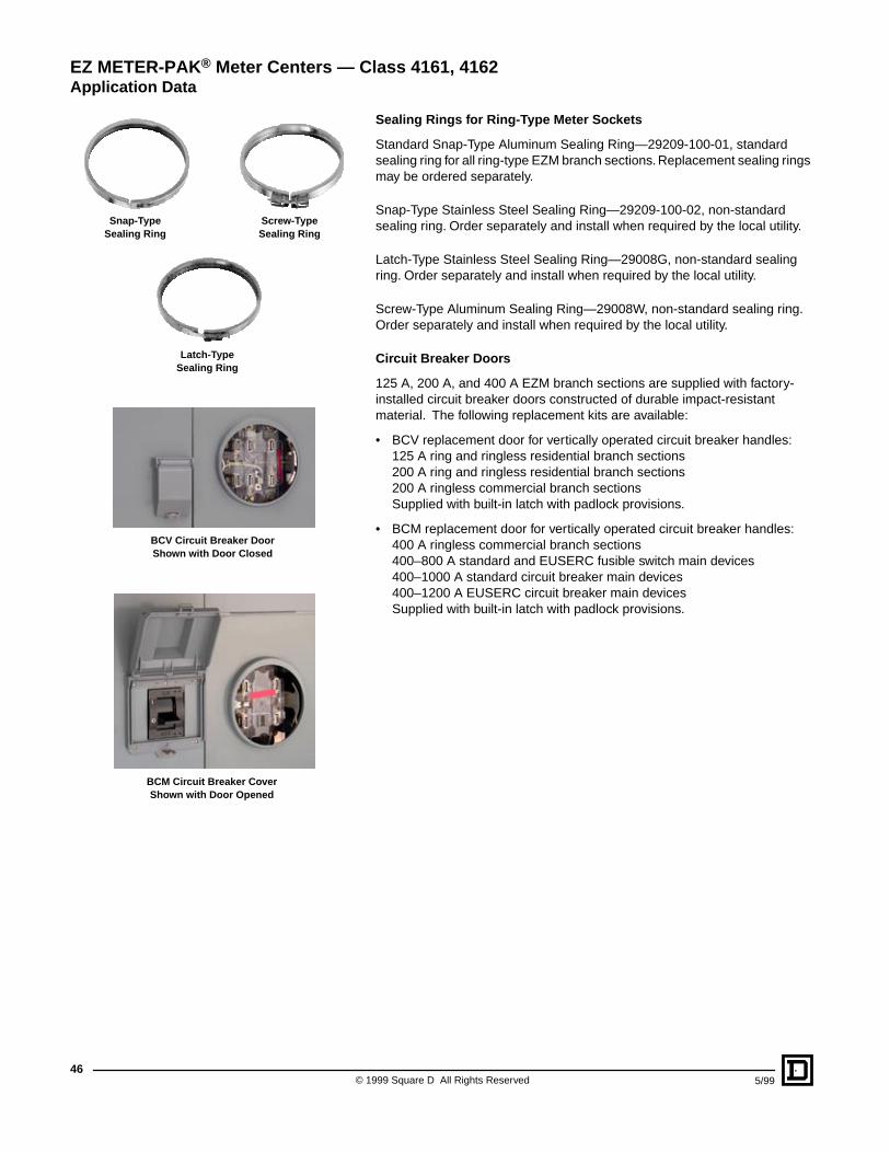
© 1999 Square D All Rights Reserved46
5/99
Sealing Rings for Ring-Type Meter Sockets
Standard Snap-Type Aluminum Sealing Ring—29209-100-01, standard sealing ring for all ring-type EZM branch sections. Replacement sealing rings may be ordered separately.
Snap-Type Stainless Steel Sealing Ring—29209-100-02, non-standard sealing ring. Order separately and install when required by the local utility.
Latch-Type Stainless Steel Sealing Ring—29008G, non-standard sealing ring. Order separately and install when required by the local utility.
Screw-Type Aluminum Sealing Ring—29008W, non-standard sealing ring. Order separately and install when required by the local utility.
Circuit Breaker Doors
125 A, 200 A, and 400 A EZM branch sections are supplied with factory-installed circuit breaker doors constructed of durable impact-resistant material. The following replacement kits are available:
• BCV replacement door for vertically operated circuit breaker handles:125 A ring and ringless residential branch sections200 A ring and ringless residential branch sections200 A ringless commercial branch sectionsSupplied with built-in latch with padlock provisions.
• BCM replacement door for vertically operated circuit breaker handles:400 A ringless commercial branch sections400–800 A standard and EUSERC fusible switch main devices400–1000 A standard circuit breaker main devices400–1200 A EUSERC circuit breaker main devicesSupplied with built-in latch with padlock provisions.
EZ METER-PAK® Meter Centers — Class 4161, 4162Application Data
BCV Circuit Breaker DoorShown with Door Closed
Snap-TypeSealing Ring
Screw-TypeSealing Ring
Latch-TypeSealing Ring
BCM Circuit Breaker CoverShown with Door Opened
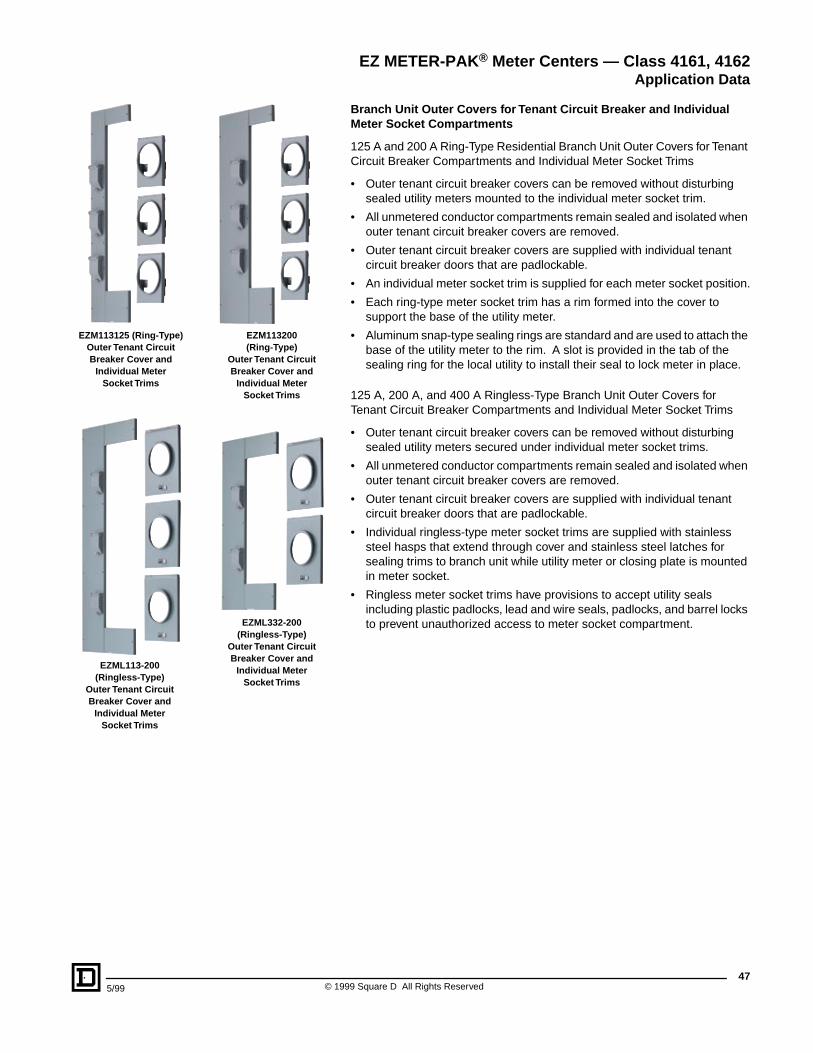
475/99 © 1999 Square D All Rights Reserved
Branch Unit Outer Covers for Tenant Circuit Breaker and Individual Meter Socket Compartments
125 A and 200 A Ring-Type Residential Branch Unit Outer Covers for Tenant Circuit Breaker Compartments and Individual Meter Socket Trims
• Outer tenant circuit breaker covers can be removed without disturbing sealed utility meters mounted to the individual meter socket trim.
• All unmetered conductor compartments remain sealed and isolated when outer tenant circuit breaker covers are removed.
• Outer tenant circuit breaker covers are supplied with individual tenant circuit breaker doors that are padlockable.
• An individual meter socket trim is supplied for each meter socket position.
• Each ring-type meter socket trim has a rim formed into the cover to support the base of the utility meter.
• Aluminum snap-type sealing rings are standard and are used to attach the base of the utility meter to the rim. A slot is provided in the tab of the sealing ring for the local utility to install their seal to lock meter in place.
125 A, 200 A, and 400 A Ringless-Type Branch Unit Outer Covers for Tenant Circuit Breaker Compartments and Individual Meter Socket Trims
• Outer tenant circuit breaker covers can be removed without disturbing sealed utility meters secured under individual meter socket trims.
• All unmetered conductor compartments remain sealed and isolated when outer tenant circuit breaker covers are removed.
• Outer tenant circuit breaker covers are supplied with individual tenant circuit breaker doors that are padlockable.
• Individual ringless-type meter socket trims are supplied with stainless steel hasps that extend through cover and stainless steel latches for sealing trims to branch unit while utility meter or closing plate is mounted in meter socket.
• Ringless meter socket trims have provisions to accept utility seals including plastic padlocks, lead and wire seals, padlocks, and barrel locks to prevent unauthorized access to meter socket compartment.
EZ METER-PAK® Meter Centers — Class 4161, 4162Application Data
EZM113125 (Ring-Type)Outer Tenant Circuit Breaker Cover and
Individual Meter Socket Trims
EZM113200 (Ring-Type)
Outer Tenant Circuit Breaker Cover and
Individual Meter Socket Trims
EZML113-200 (Ringless-Type)
Outer Tenant CircuitBreaker Cover and
Individual MeterSocket Trims
EZML332-200 (Ringless-Type)
Outer Tenant Circuit Breaker Cover and
Individual Meter Socket Trims
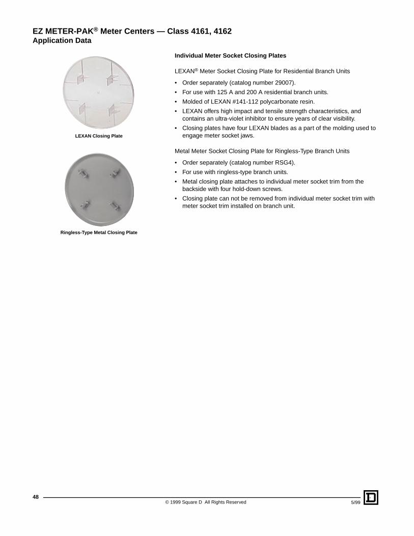
© 1999 Square D All Rights Reserved48
5/99
Individual Meter Socket Closing Plates
LEXAN® Meter Socket Closing Plate for Residential Branch Units
• Order separately (catalog number 29007).
• For use with 125 A and 200 A residential branch units.
• Molded of LEXAN #141-112 polycarbonate resin.
• LEXAN offers high impact and tensile strength characteristics, and contains an ultra-violet inhibitor to ensure years of clear visibility.
• Closing plates have four LEXAN blades as a part of the molding used to engage meter socket jaws.
Metal Meter Socket Closing Plate for Ringless-Type Branch Units
• Order separately (catalog number RSG4).
• For use with ringless-type branch units.
• Metal closing plate attaches to individual meter socket trim from the backside with four hold-down screws.
• Closing plate can not be removed from individual meter socket trim with meter socket trim installed on branch unit.
EZ METER-PAK® Meter Centers — Class 4161, 4162Application Data
LEXAN Closing Plate
Ringless-Type Metal Closing Plate
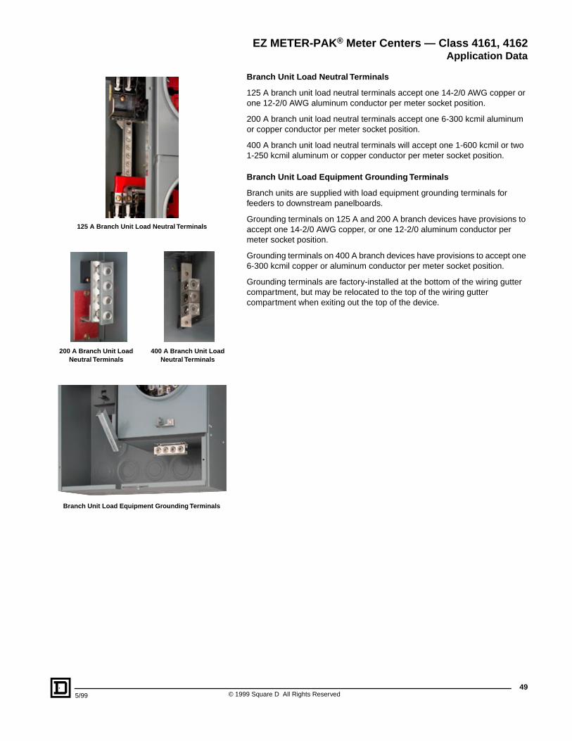
495/99 © 1999 Square D All Rights Reserved
Branch Unit Load Neutral Terminals
125 A branch unit load neutral terminals accept one 14-2/0 AWG copper or one 12-2/0 AWG aluminum conductor per meter socket position.
200 A branch unit load neutral terminals accept one 6-300 kcmil aluminum or copper conductor per meter socket position.
400 A branch unit load neutral terminals will accept one 1-600 kcmil or two 1-250 kcmil aluminum or copper conductor per meter socket position.
Branch Unit Load Equipment Grounding Terminals
Branch units are supplied with load equipment grounding terminals for feeders to downstream panelboards.
Grounding terminals on 125 A and 200 A branch devices have provisions to accept one 14-2/0 AWG copper, or one 12-2/0 aluminum conductor per meter socket position.
Grounding terminals on 400 A branch devices have provisions to accept one 6-300 kcmil copper or aluminum conductor per meter socket position.
Grounding terminals are factory-installed at the bottom of the wiring gutter compartment, but may be relocated to the top of the wiring gutter compartment when exiting out the top of the device.
EZ METER-PAK® Meter Centers — Class 4161, 4162Application Data
125 A Branch Unit Load Neutral Terminals
200 A Branch Unit Load Neutral Terminals
400 A Branch Unit Load Neutral Terminals
Branch Unit Load Equipment Grounding Terminals
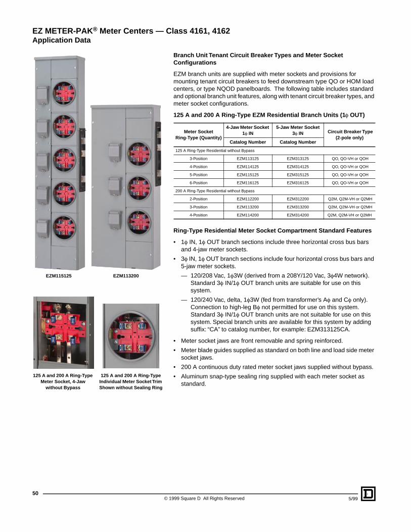
© 1999 Square D All Rights Reserved50
5/99
Branch Unit Tenant Circuit Breaker Types and Meter Socket Configurations
EZM branch units are supplied with meter sockets and provisions for mounting tenant circuit breakers to feed downstream type QO or HOM load centers, or type NQOD panelboards. The following table includes standard and optional branch unit features, along with tenant circuit breaker types, and meter socket configurations.
125 A and 200 A Ring-Type EZM Residential Branch Units (1 f OUT)
Ring-Type Residential Meter Socket Compartment Standard Features
• 1f IN, 1f OUT branch sections include three horizontal cross bus bars and 4-jaw meter sockets.
• 3f IN, 1f OUT branch sections include four horizontal cross bus bars and 5-jaw meter sockets.
— 120/208 Vac, 1f3W (derived from a 208Y/120 Vac, 3f4W network). Standard 3f IN/1f OUT branch units are suitable for use on this system.
— 120/240 Vac, delta, 1f3W (fed from transformer’s Af and Cf only). Connection to high-leg Bf not permitted for use on this system. Standard 3f IN/1f OUT branch units are not suitable for use on this system. Special branch units are available for this system by adding suffix: “CA” to catalog number, for example: EZM313125CA.
• Meter socket jaws are front removable and spring reinforced.
• Meter blade guides supplied as standard on both line and load side meter socket jaws.
• 200 A continuous duty rated meter socket jaws supplied without bypass.
• Aluminum snap-type sealing ring supplied with each meter socket as standard.
Meter SocketRing-Type (Quantity)
4-Jaw Meter Socket 1f IN
5-Jaw Meter Socket 3f IN Circuit Breaker Type
(2-pole only)Catalog Number Catalog Number
125 A Ring-Type Residential without Bypass
3-Position EZM113125 EZM313125 QO, QO-VH or QOH
4-Position EZM114125 EZM314125 QO, QO-VH or QOH
5-Position EZM115125 EZM315125 QO, QO-VH or QOH
6-Position EZM116125 EZM316125 QO, QO-VH or QOH
200 A Ring-Type Residential without Bypass
2-Position EZM112200 EZM312200 Q2M, Q2M-VH or Q2MH
3-Position EZM113200 EZM313200 Q2M, Q2M-VH or Q2MH
4-Position EZM114200 EZM314200 Q2M, Q2M-VH or Q2MH
125 A and 200 A Ring-Type Meter Socket, 4-Jaw
without Bypass
125 A and 200 A Ring-Type Individual Meter Socket Trim Shown without Sealing Ring
EZM115125 EZM113200
EZ METER-PAK® Meter Centers — Class 4161, 4162Application Data
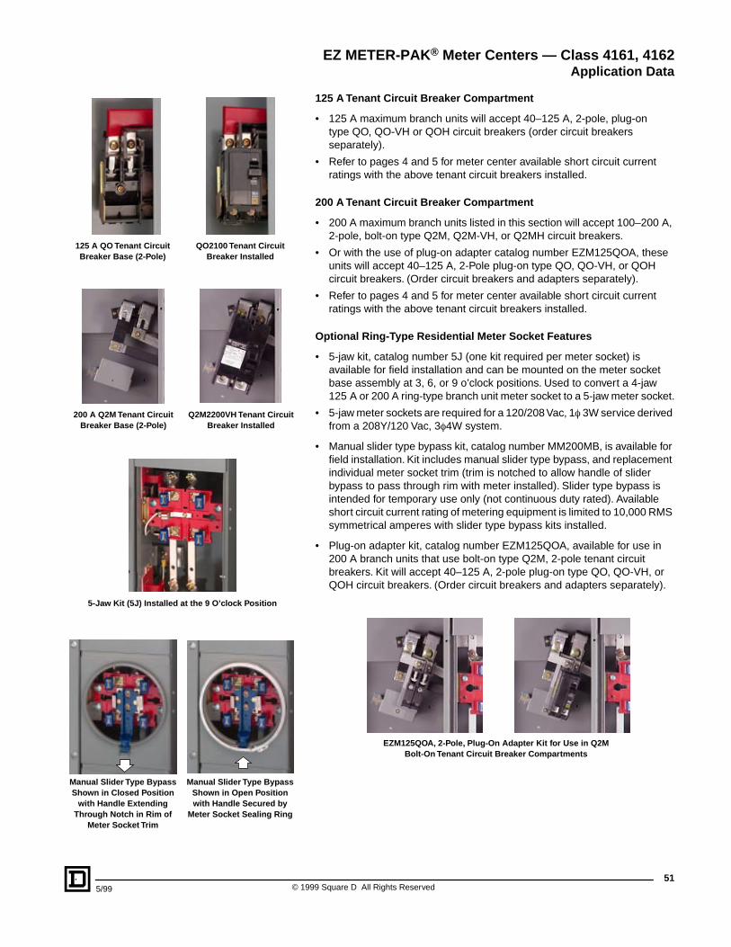
515/99 © 1999 Square D All Rights Reserved
125 A Tenant Circuit Breaker Compartment
• 125 A maximum branch units will accept 40–125 A, 2-pole, plug-on type QO, QO-VH or QOH circuit breakers (order circuit breakers separately).
• Refer to pages 4 and 5 for meter center available short circuit current ratings with the above tenant circuit breakers installed.
200 A Tenant Circuit Breaker Compartment
• 200 A maximum branch units listed in this section will accept 100–200 A, 2-pole, bolt-on type Q2M, Q2M-VH, or Q2MH circuit breakers.
• Or with the use of plug-on adapter catalog number EZM125QOA, these units will accept 40–125 A, 2-Pole plug-on type QO, QO-VH, or QOH circuit breakers. (Order circuit breakers and adapters separately).
• Refer to pages 4 and 5 for meter center available short circuit current ratings with the above tenant circuit breakers installed.
Optional Ring-Type Residential Meter Socket Features
• 5-jaw kit, catalog number 5J (one kit required per meter socket) is available for field installation and can be mounted on the meter socket base assembly at 3, 6, or 9 o’clock positions. Used to convert a 4-jaw 125 A or 200 A ring-type branch unit meter socket to a 5-jaw meter socket.
• 5-jaw meter sockets are required for a 120/208 Vac, 1f 3W service derived from a 208Y/120 Vac, 3f4W system.
• Manual slider type bypass kit, catalog number MM200MB, is available for field installation. Kit includes manual slider type bypass, and replacement individual meter socket trim (trim is notched to allow handle of slider bypass to pass through rim with meter installed). Slider type bypass is intended for temporary use only (not continuous duty rated). Available short circuit current rating of metering equipment is limited to 10,000 RMS symmetrical amperes with slider type bypass kits installed.
• Plug-on adapter kit, catalog number EZM125QOA, available for use in 200 A branch units that use bolt-on type Q2M, 2-pole tenant circuit breakers. Kit will accept 40–125 A, 2-pole plug-on type QO, QO-VH, or QOH circuit breakers. (Order circuit breakers and adapters separately).
EZM125QOA, 2-Pole, Plug-On Adapter Kit for Use in Q2M Bolt-On Tenant Circuit Breaker Compartments
EZ METER-PAK® Meter Centers — Class 4161, 4162Application Data
Manual Slider Type Bypass Shown in Closed Position
with Handle Extending Through Notch in Rim of
Meter Socket Trim
Manual Slider Type Bypass Shown in Open Position with Handle Secured by
Meter Socket Sealing Ring
200 A Q2M Tenant Circuit Breaker Base (2-Pole)
125 A QO Tenant Circuit Breaker Base (2-Pole)
QO2100 Tenant Circuit Breaker Installed
Q2M2200VH Tenant Circuit Breaker Installed
5-Jaw Kit (5J) Installed at the 9 O’clock Position
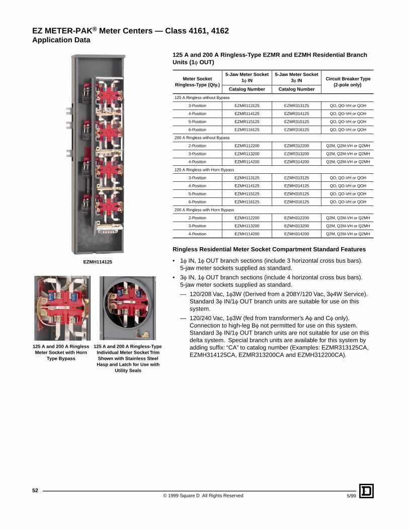
© 1999 Square D All Rights Reserved52
5/99
125 A and 200 A Ringless-Type EZMR and EZMH Residential Branch Units (1 f OUT)
Ringless Residential Meter Socket Compartment Standard Features
• 1f IN, 1f OUT branch sections (include 3 horizontal cross bus bars). 5-jaw meter sockets supplied as standard.
• 3f IN, 1f OUT branch sections (include 4 horizontal cross bus bars). 5-jaw meter sockets supplied as standard.
— 120/208 Vac, 1f3W (Derived from a 208Y/120 Vac, 3f4W Service). Standard 3f IN/1f OUT branch units are suitable for use on this system.
— 120/240 Vac, 1f3W (fed from transformer’s Af and Cf only). Connection to high-leg Bf not permitted for use on this system. Standard 3f IN/1f OUT branch units are not suitable for use on this delta system. Special branch units are available for this system by adding suffix: “CA” to catalog number (Examples: EZMR313125CA, EZMH314125CA, EZMR313200CA and EZMH312200CA).
Meter SocketRingless-Type (Qty.)
5-Jaw Meter Socket1f IN
5-Jaw Meter Socket3f IN Circuit Breaker Type
(2-pole only)Catalog Number Catalog Number
125 A Ringless without Bypass
3-Position EZMR113125 EZMR313125 QO, QO-VH or QOH
4-Position EZMR114125 EZMR314125 QO, QO-VH or QOH
5-Position EZMR115125 EZMR315125 QO, QO-VH or QOH
6-Position EZMR116125 EZMR316125 QO, QO-VH or QOH
200 A Ringless without Bypass
2-Position EZMR112200 EZMR312200 Q2M, Q2M-VH or Q2MH
3-Position EZMR113200 EZMR313200 Q2M, Q2M-VH or Q2MH
4-Position EZMR114200 EZMR314200 Q2M, Q2M-VH or Q2MH
125 A Ringless with Horn Bypass
3-Position EZMH113125 EZMH313125 QO, QO-VH or QOH
4-Position EZMH114125 EZMH314125 QO, QO-VH or QOH
5-Position EZMH115125 EZMH315125 QO, QO-VH or QOH
6-Position EZMH116125 EZMH316125 QO, QO-VH or QOH
200 A Ringless with Horn Bypass
2-Position EZMH112200 EZMH312200 Q2M, Q2M-VH or Q2MH
3-Position EZMH113200 EZMH313200 Q2M, Q2M-VH or Q2MH
4-Position EZMH114200 EZMH314200 Q2M, Q2M-VH or Q2MH
EZ METER-PAK® Meter Centers — Class 4161, 4162Application Data
125 A and 200 A Ringless Meter Socket with Horn
Type Bypass
125 A and 200 A Ringless-Type Individual Meter Socket Trim Shown with Stainless Steel Hasp and Latch for Use with
Utility Seals
EZMH114125
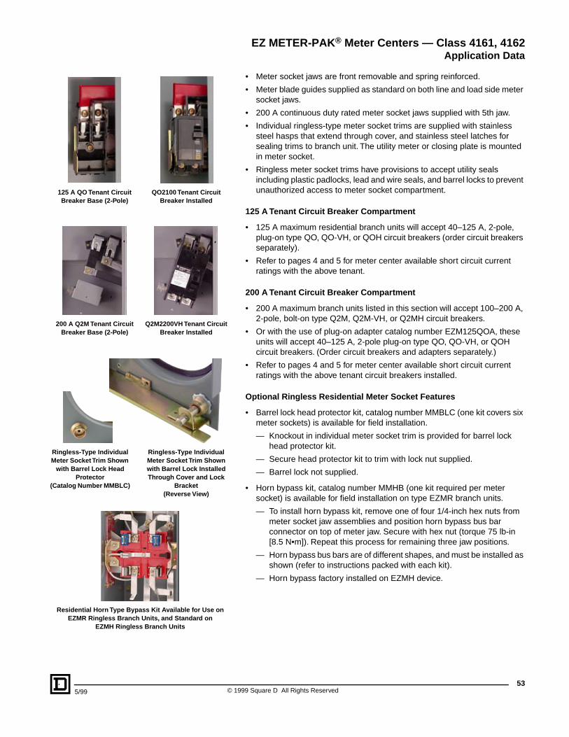
535/99 © 1999 Square D All Rights Reserved
• Meter socket jaws are front removable and spring reinforced.
• Meter blade guides supplied as standard on both line and load side meter socket jaws.
• 200 A continuous duty rated meter socket jaws supplied with 5th jaw.
• Individual ringless-type meter socket trims are supplied with stainless steel hasps that extend through cover, and stainless steel latches for sealing trims to branch unit. The utility meter or closing plate is mounted in meter socket.
• Ringless meter socket trims have provisions to accept utility seals including plastic padlocks, lead and wire seals, and barrel locks to prevent unauthorized access to meter socket compartment.
125 A Tenant Circuit Breaker Compartment
• 125 A maximum residential branch units will accept 40–125 A, 2-pole, plug-on type QO, QO-VH, or QOH circuit breakers (order circuit breakers separately).
• Refer to pages 4 and 5 for meter center available short circuit current ratings with the above tenant.
200 A Tenant Circuit Breaker Compartment
• 200 A maximum branch units listed in this section will accept 100–200 A, 2-pole, bolt-on type Q2M, Q2M-VH, or Q2MH circuit breakers.
• Or with the use of plug-on adapter catalog number EZM125QOA, these units will accept 40–125 A, 2-pole plug-on type QO, QO-VH, or QOH circuit breakers. (Order circuit breakers and adapters separately.)
• Refer to pages 4 and 5 for meter center available short circuit current ratings with the above tenant circuit breakers installed.
Optional Ringless Residential Meter Socket Features
• Barrel lock head protector kit, catalog number MMBLC (one kit covers six meter sockets) is available for field installation.
— Knockout in individual meter socket trim is provided for barrel lock head protector kit.
— Secure head protector kit to trim with lock nut supplied.
— Barrel lock not supplied.
• Horn bypass kit, catalog number MMHB (one kit required per meter socket) is available for field installation on type EZMR branch units.
— To install horn bypass kit, remove one of four 1/4-inch hex nuts from meter socket jaw assemblies and position horn bypass bus bar connector on top of meter jaw. Secure with hex nut (torque 75 lb-in [8.5 N•m]). Repeat this process for remaining three jaw positions.
— Horn bypass bus bars are of different shapes, and must be installed as shown (refer to instructions packed with each kit).
— Horn bypass factory installed on EZMH device.
EZ METER-PAK® Meter Centers — Class 4161, 4162Application Data
125 A QO Tenant Circuit Breaker Base (2-Pole)
QO2100 Tenant Circuit Breaker Installed
Q2M2200VH Tenant Circuit Breaker Installed
200 A Q2M Tenant Circuit Breaker Base (2-Pole)
Ringless-Type Individual Meter Socket Trim Shown with Barrel Lock Installed Through Cover and Lock
Bracket(Reverse View)
Ringless-Type Individual Meter Socket Trim Shown
with Barrel Lock Head Protector
(Catalog Number MMBLC)
Residential Horn Type Bypass Kit Available for Use on EZMR Ringless Branch Units, and Standard on
EZMH Ringless Branch Units
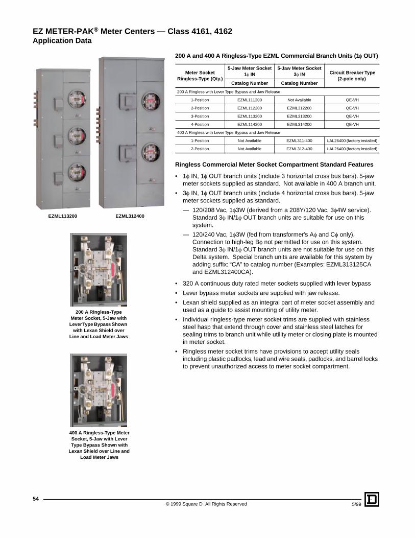
© 1999 Square D All Rights Reserved54
5/99
200 A and 400 A Ringless-Type EZML Commercial Branch Units (1 f OUT)
Ringless Commercial Meter Socket Compartment Standard Features
• 1f IN, 1f OUT branch units (include 3 horizontal cross bus bars). 5-jaw meter sockets supplied as standard. Not available in 400 A branch unit.
• 3f IN, 1f OUT branch units (include 4 horizontal cross bus bars). 5-jaw meter sockets supplied as standard.
— 120/208 Vac, 1f3W (derived from a 208Y/120 Vac, 3f4W service). Standard 3f IN/1f OUT branch units are suitable for use on this system.
— 120/240 Vac, 1f3W (fed from transformer’s Af and Cf only). Connection to high-leg Bf not permitted for use on this system. Standard 3f IN/1f OUT branch units are not suitable for use on this Delta system. Special branch units are available for this system by adding suffix: “CA” to catalog number (Examples: EZML313125CA and EZML312400CA).
• 320 A continuous duty rated meter sockets supplied with lever bypass
• Lever bypass meter sockets are supplied with jaw release.
• Lexan shield supplied as an integral part of meter socket assembly and used as a guide to assist mounting of utility meter.
• Individual ringless-type meter socket trims are supplied with stainless steel hasp that extend through cover and stainless steel latches for sealing trims to branch unit while utility meter or closing plate is mounted in meter socket.
• Ringless meter socket trims have provisions to accept utility seals including plastic padlocks, lead and wire seals, padlocks, and barrel locks to prevent unauthorized access to meter socket compartment.
Meter SocketRingless-Type (Qty.)
5-Jaw Meter Socket1f IN
5-Jaw Meter Socket3f IN Circuit Breaker Type
(2-pole only)Catalog Number Catalog Number
200 A Ringless with Lever Type Bypass and Jaw Release
1-Position EZML111200 Not Available QE-VH
2-Position EZML112200 EZML312200 QE-VH
3-Position EZML113200 EZML313200 QE-VH
4-Position EZML114200 EZML314200 QE-VH
400 A Ringless with Lever Type Bypass and Jaw Release
1-Position Not Available EZML311-400 LAL26400 (factory installed)
2-Position Not Available EZML312-400 LAL26400 (factory installed)
EZ METER-PAK® Meter Centers — Class 4161, 4162Application Data
200 A Ringless-Type Meter Socket, 5-Jaw with
Lever Type Bypass Shown with Lexan Shield over
Line and Load Meter Jaws
400 A Ringless-Type Meter Socket, 5-Jaw with Lever Type Bypass Shown with
Lexan Shield over Line and Load Meter Jaws
EZML113200 EZML312400
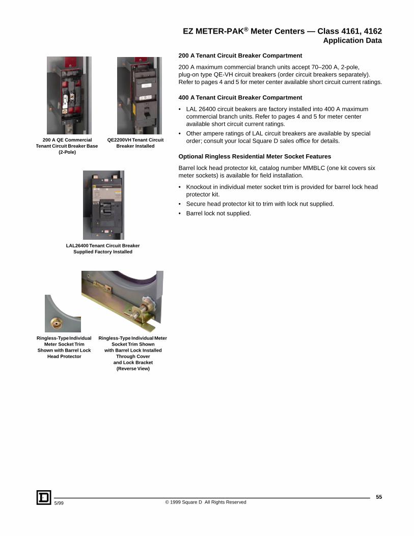
555/99 © 1999 Square D All Rights Reserved
200 A Tenant Circuit Breaker Compartment
200 A maximum commercial branch units accept 70–200 A, 2-pole, plug-on type QE-VH circuit breakers (order circuit breakers separately). Refer to pages 4 and 5 for meter center available short circuit current ratings.
400 A Tenant Circuit Breaker Compartment
• LAL 26400 circuit beakers are factory installed into 400 A maximum commercial branch units. Refer to pages 4 and 5 for meter center available short circuit current ratings.
• Other ampere ratings of LAL circuit breakers are available by special order; consult your local Square D sales office for details.
Optional Ringless Residential Meter Socket Features
Barrel lock head protector kit, catalog number MMBLC (one kit covers six meter sockets) is available for field installation.
• Knockout in individual meter socket trim is provided for barrel lock head protector kit.
• Secure head protector kit to trim with lock nut supplied.
• Barrel lock not supplied.
EZ METER-PAK® Meter Centers — Class 4161, 4162Application Data
QE2200VH Tenant Circuit Breaker Installed
200 A QE Commercial Tenant Circuit Breaker Base
(2-Pole)
LAL26400 Tenant Circuit Breaker Supplied Factory Installed
Ringless-Type Individual Meter Socket Trim
Shown with Barrel Lock Head Protector
Ringless-Type Individual Meter Socket Trim Shown
with Barrel Lock Installed Through Cover
and Lock Bracket(Reverse View)
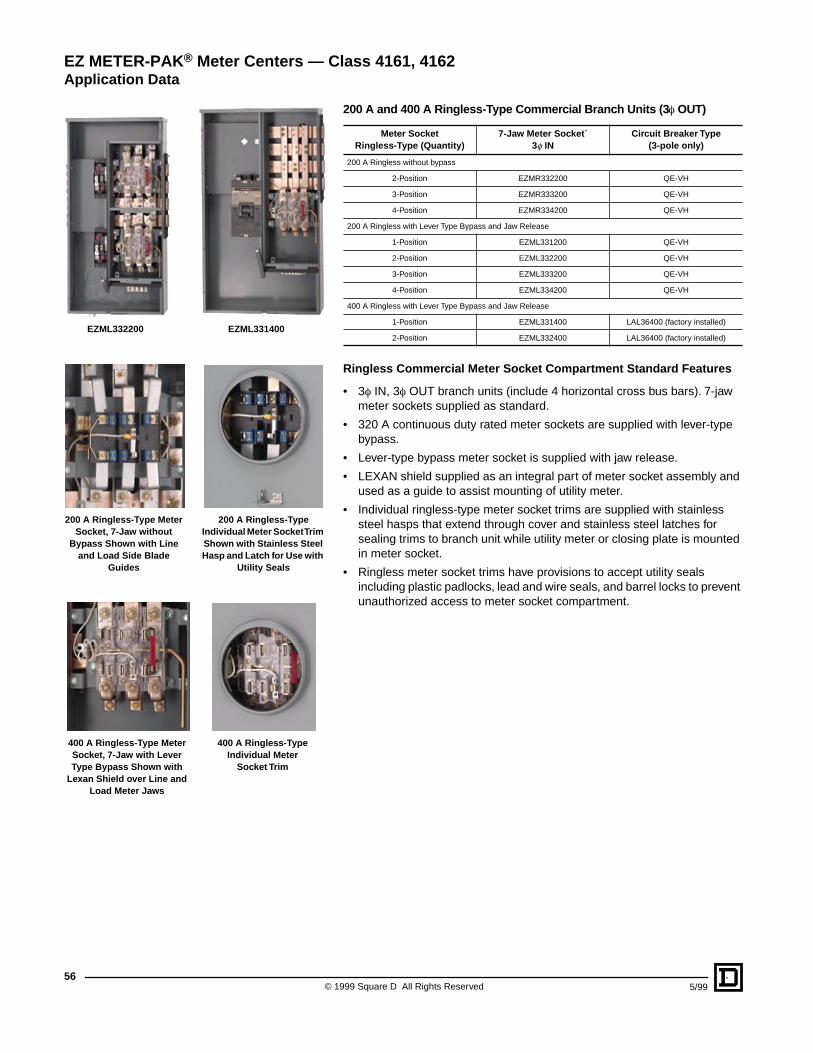
© 1999 Square D All Rights Reserved56
5/99
200 A and 400 A Ringless-Type Commercial Branch Units (3 f OUT)
Ringless Commercial Meter Socket Compartment Standard Features
• 3f IN, 3f OUT branch units (include 4 horizontal cross bus bars). 7-jaw meter sockets supplied as standard.
• 320 A continuous duty rated meter sockets are supplied with lever-type bypass.
• Lever-type bypass meter socket is supplied with jaw release.
• LEXAN shield supplied as an integral part of meter socket assembly and used as a guide to assist mounting of utility meter.
• Individual ringless-type meter socket trims are supplied with stainless steel hasps that extend through cover and stainless steel latches for sealing trims to branch unit while utility meter or closing plate is mounted in meter socket.
• Ringless meter socket trims have provisions to accept utility seals including plastic padlocks, lead and wire seals, and barrel locks to prevent unauthorized access to meter socket compartment.
Meter SocketRingless-Type (Quantity)
7-Jaw Meter Socket`3f IN
Circuit Breaker Type(3-pole only)
200 A Ringless without bypass
2-Position EZMR332200 QE-VH
3-Position EZMR333200 QE-VH
4-Position EZMR334200 QE-VH
200 A Ringless with Lever Type Bypass and Jaw Release
1-Position EZML331200 QE-VH
2-Position EZML332200 QE-VH
3-Position EZML333200 QE-VH
4-Position EZML334200 QE-VH
400 A Ringless with Lever Type Bypass and Jaw Release
1-Position EZML331400 LAL36400 (factory installed)
2-Position EZML332400 LAL36400 (factory installed)
EZ METER-PAK® Meter Centers — Class 4161, 4162Application Data
200 A Ringless-Type Meter Socket, 7-Jaw without
Bypass Shown with Line and Load Side Blade
Guides
200 A Ringless-Type Individual Meter Socket Trim Shown with Stainless Steel Hasp and Latch for Use with
Utility Seals
400 A Ringless-Type Meter Socket, 7-Jaw with Lever Type Bypass Shown with
Lexan Shield over Line and Load Meter Jaws
400 A Ringless-Type Individual Meter
Socket Trim
EZML332200 EZML331400
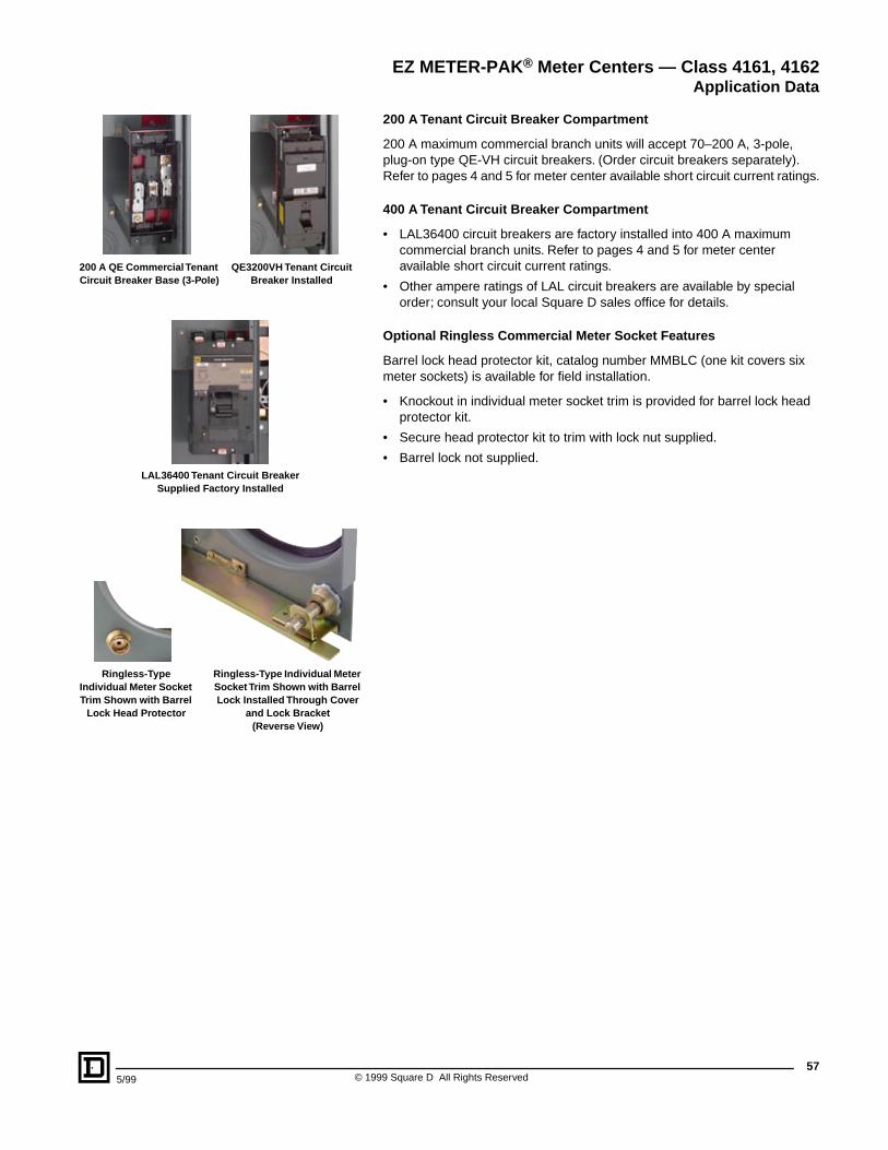
575/99 © 1999 Square D All Rights Reserved
200 A Tenant Circuit Breaker Compartment
200 A maximum commercial branch units will accept 70–200 A, 3-pole, plug-on type QE-VH circuit breakers. (Order circuit breakers separately). Refer to pages 4 and 5 for meter center available short circuit current ratings.
400 A Tenant Circuit Breaker Compartment
• LAL36400 circuit breakers are factory installed into 400 A maximum commercial branch units. Refer to pages 4 and 5 for meter center available short circuit current ratings.
• Other ampere ratings of LAL circuit breakers are available by special order; consult your local Square D sales office for details.
Optional Ringless Commercial Meter Socket Features
Barrel lock head protector kit, catalog number MMBLC (one kit covers six meter sockets) is available for field installation.
• Knockout in individual meter socket trim is provided for barrel lock head protector kit.
• Secure head protector kit to trim with lock nut supplied.
• Barrel lock not supplied.
EZ METER-PAK® Meter Centers — Class 4161, 4162Application Data
200 A QE Commercial Tenant Circuit Breaker Base (3-Pole)
QE3200VH Tenant Circuit Breaker Installed
LAL36400 Tenant Circuit Breaker Supplied Factory Installed
Ringless-Type Individual Meter Socket Trim Shown with Barrel Lock Installed Through Cover
and Lock Bracket(Reverse View)
Ringless-Type Individual Meter Socket Trim Shown with Barrel
Lock Head Protector
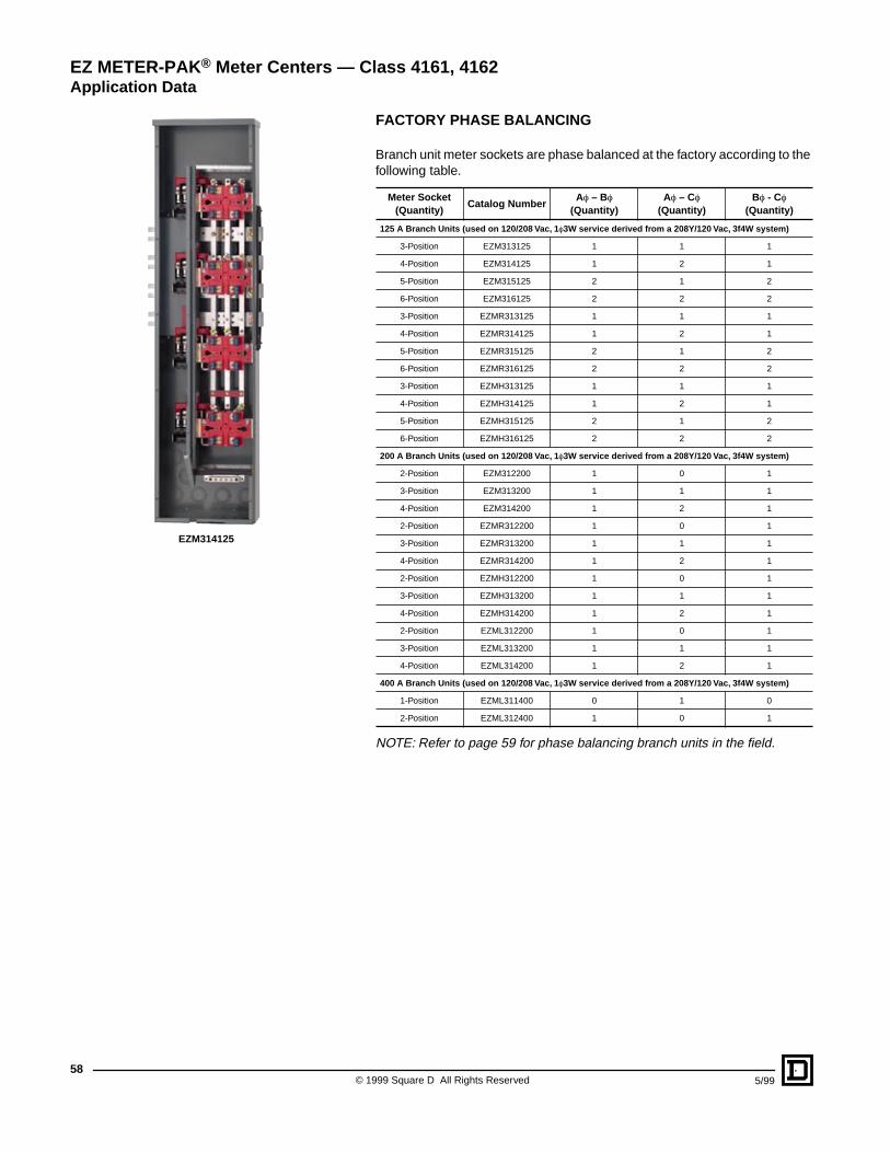
© 1999 Square D All Rights Reserved58
5/99
FACTORY PHASE BALANCING
Branch unit meter sockets are phase balanced at the factory according to the following table.
NOTE: Refer to page 59 for phase balancing branch units in the field.
Meter Socket (Quantity)
Catalog NumberAf – Bf
(Quantity)Af – Cf
(Quantity)Bf - Cf
(Quantity)
125 A Branch Units (used on 120/208 Vac, 1 f3W service derived from a 208Y/120 Vac, 3f4W system)
3-Position EZM313125 1 1 1
4-Position EZM314125 1 2 1
5-Position EZM315125 2 1 2
6-Position EZM316125 2 2 2
3-Position EZMR313125 1 1 1
4-Position EZMR314125 1 2 1
5-Position EZMR315125 2 1 2
6-Position EZMR316125 2 2 2
3-Position EZMH313125 1 1 1
4-Position EZMH314125 1 2 1
5-Position EZMH315125 2 1 2
6-Position EZMH316125 2 2 2
200 A Branch Units (used on 120/208 Vac, 1 f3W service derived from a 208Y/120 Vac, 3f4W system)
2-Position EZM312200 1 0 1
3-Position EZM313200 1 1 1
4-Position EZM314200 1 2 1
2-Position EZMR312200 1 0 1
3-Position EZMR313200 1 1 1
4-Position EZMR314200 1 2 1
2-Position EZMH312200 1 0 1
3-Position EZMH313200 1 1 1
4-Position EZMH314200 1 2 1
2-Position EZML312200 1 0 1
3-Position EZML313200 1 1 1
4-Position EZML314200 1 2 1
400 A Branch Units (used on 120/208 Vac, 1 f3W service derived from a 208Y/120 Vac, 3f4W system)
1-Position EZML311400 0 1 0
2-Position EZML312400 1 0 1
EZ METER-PAK® Meter Centers — Class 4161, 4162Application Data
EZM314125
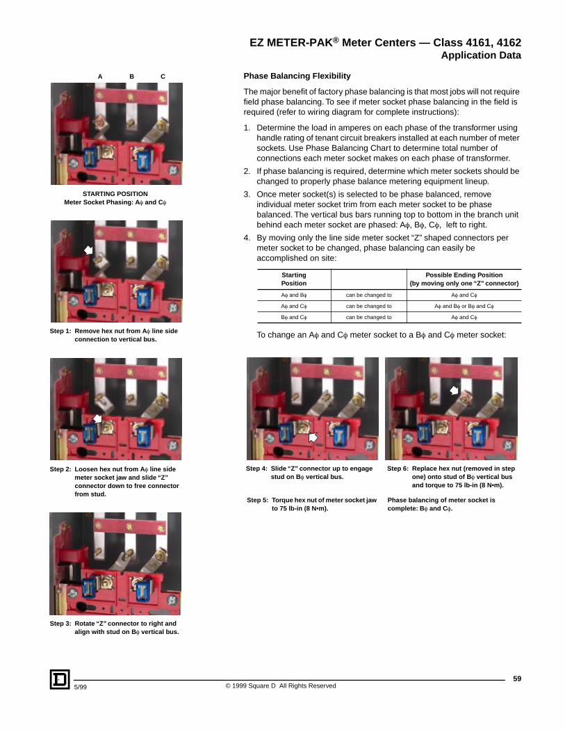
595/99 © 1999 Square D All Rights Reserved
Phase Balancing Flexibility
The major benefit of factory phase balancing is that most jobs will not require field phase balancing. To see if meter socket phase balancing in the field is required (refer to wiring diagram for complete instructions):
1. Determine the load in amperes on each phase of the transformer using handle rating of tenant circuit breakers installed at each number of meter sockets. Use Phase Balancing Chart to determine total number of connections each meter socket makes on each phase of transformer.
2. If phase balancing is required, determine which meter sockets should be changed to properly phase balance metering equipment lineup.
3. Once meter socket(s) is selected to be phase balanced, remove individual meter socket trim from each meter socket to be phase balanced. The vertical bus bars running top to bottom in the branch unit behind each meter socket are phased: Af, Bf, Cf, left to right.
4. By moving only the line side meter socket “Z” shaped connectors per meter socket to be changed, phase balancing can easily be accomplished on site:
To change an Af and Cf meter socket to a Bf and Cf meter socket:
StartingPosition
Possible Ending Position(by moving only one “Z” connector)
Af and Bf can be changed to Af and Cf
Af and Cf can be changed to Af and Bf or Bf and Cf
Bf and Cf can be changed to Af and Cf
Step 4: Slide “Z” connector up to engage stud on B f vertical bus.
Step 6: Replace hex nut (removed in step one) onto stud of B f vertical bus and torque to 75 lb-in (8 N•m).
Step 5: Torque hex nut of meter socket jaw to 75 lb-in (8 N•m).
Phase balancing of meter socket is complete: B f and Cf.
EZ METER-PAK® Meter Centers — Class 4161, 4162Application Data
STARTING POSITIONMeter Socket Phasing: A f and Cf
Step 2: Loosen hex nut from A f line side meter socket jaw and slide “Z” connector down to free connector from stud.
Step 3: Rotate “Z” connector to right and align with stud on B f vertical bus.
Step 1: Remove hex nut from A f line side connection to vertical bus.
A B C
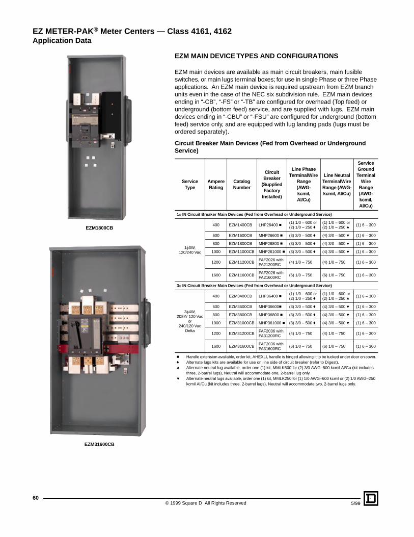
© 1999 Square D All Rights Reserved60
5/99
EZM MAIN DEVICE TYPES AND CONFIGURATIONS
EZM main devices are available as main circuit breakers, main fusible switches, or main lugs terminal boxes; for use in single Phase or three Phase applications. An EZM main device is required upstream from EZM branch units even in the case of the NEC six subdivision rule. EZM main devices ending in “-CB”, “-FS” or “-TB” are configured for overhead (Top feed) or underground (bottom feed) service, and are supplied with lugs. EZM main devices ending in “-CBU” or “-FSU” are configured for underground (bottom feed) service only, and are equipped with lug landing pads (lugs must be ordered separately).
Circuit Breaker Main Devices (Fed from Overhead or Underground Service)
Service Type
AmpereRating
Catalog Number
Circuit Breaker
(Supplied Factory
Installed)
Line Phase Terminal Wire
Range(AWG-kcmil, Al/Cu)
Line Neutral Terminal Wire Range (AWG-kcmil, Al/Cu)
Service Ground Terminal
Wire Range (AWG-kcmil, Al/Cu)
1f IN Circuit Breaker Main Devices (Fed from Overhead or Underground Service)
1f3W, 120/240 Vac
400 EZM1400CB LHP26400 c(1) 1/0 – 600 or (2) 1/0 – 250 f
(1) 1/0 – 600 or (2) 1/0 – 250 q
(1) 6 – 300
600 EZM1600CB MHP26600 c (3) 3/0 – 500 f (4) 3/0 – 500 p (1) 6 – 300
800 EZM1800CB MHP26800 c (3) 3/0 – 500 f (4) 3/0 – 500 p (1) 6 – 300
1000 EZM11000CB MHP261000 c (3) 3/0 – 500 f (4) 3/0 – 500 p (1) 6 – 300
1200 EZM11200CBPAF2026 with PA21200RC
(4) 1/0 – 750 (4) 1/0 – 750 (1) 6 – 300
1600 EZM11600CBPAF2026 with PA21600RC
(6) 1/0 – 750 (6) 1/0 – 750 (1) 6 – 300
3f IN Circuit Breaker Main Devices (Fed from Overhead or Underground Service)
3f4W, 208Y/ 120 Vac
or 240/120 Vac
Delta
400 EZM3400CB LHP36400 c(1) 1/0 – 600 or (2) 1/0 – 250 f
(1) 1/0 – 600 or (2) 1/0 – 250 q
(1) 6 – 300
600 EZM3600CB MHP36600c (3) 3/0 – 500 f (4) 3/0 – 500 p (1) 6 – 300
800 EZM3800CB MHP36800 c (3) 3/0 – 500 f (4) 3/0 – 500 p (1) 6 – 300
1000 EZM31000CB MHP361000 c (3) 3/0 – 500 f (4) 3/0 – 500 p (1) 6 – 300
1200 EZM31200CBPAF2036 with PA31200RC
(4) 1/0 – 750 (4) 1/0 – 750 (1) 6 – 300
1600 EZM31600CBPAF2036 with PA31600RC
(6) 1/0 – 750 (6) 1/0 – 750 (1) 6 – 300
c Handle extension available, order kit, AHEXLI, handle is hinged allowing it to be tucked under door on cover.f Alternate lugs kits are available for use on line side of circuit breaker (refer to Digest).q Alternate neutral lug available, order one (1) kit, MMLK500 for (2) 3/0 AWG–500 kcmil Al/Cu (kit includes
three, 2-barrel lugs), Neutral will accommodate one, 2-barrel lug only.p Alternate neutral lugs available, order one (1) kit, MMLK250 for (1) 1/0 AWG–600 kcmil or (2) 1/0 AWG–250
kcmil Al/Cu (kit includes three, 2-barrel lugs), Neutral will accommodate two, 2-barrel lugs only.
EZ METER-PAK® Meter Centers — Class 4161, 4162Application Data
EZM1800CB
EZM31600CB
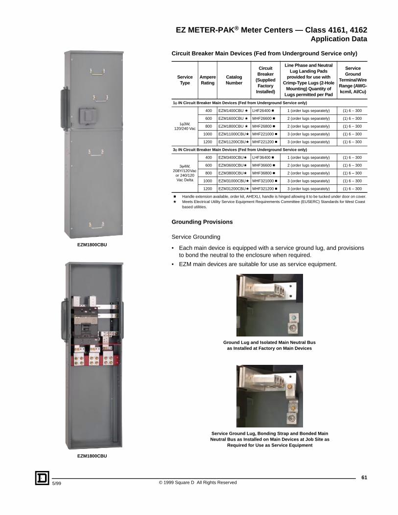
615/99 © 1999 Square D All Rights Reserved
Circuit Breaker Main Devices (Fed from Underground Service only)
Grounding Provisions
Service Grounding
• Each main device is equipped with a service ground lug, and provisions to bond the neutral to the enclosure when required.
• EZM main devices are suitable for use as service equipment.
Service Type
AmpereRating
Catalog Number
Circuit Breaker
(Supplied Factory
Installed)
Line Phase and Neutral Lug Landing Pads
provided for use with Crimp-Type Lugs (2-Hole
Mounting) Quantity of Lugs permitted per Pad
Service Ground
Terminal Wire Range (AWG-kcmil, Al/Cu)
1f IN Circuit Breaker Main Devices (Fed from Underground Service only)
1f3W, 120/240 Vac
400 EZM1400CBU a LHF26400 c 1 (order lugs separately) (1) 6 – 300
600 EZM1600CBU a MHF26600 c 2 (order lugs separately) (1) 6 – 300
800 EZM1800CBU a MHF26800 c 2 (order lugs separately) (1) 6 – 300
1000 EZM11000CBUa MHF221000 c 3 (order lugs separately) (1) 6 – 300
1200 EZM11200CBUa MHF221200 c 3 (order lugs separately) (1) 6 – 300
3f IN Circuit Breaker Main Devices (Fed from Underground Service only)
3f4W, 208Y/120 Vac
or 240/120 Vac Delta
400 EZM3400CBUa LHF36400 c 1 (order lugs separately) (1) 6 – 300
600 EZM3600CBUa MHF36600 c 2 (order lugs separately) (1) 6 – 300
800 EZM3800CBUa MHF36800 c 2 (order lugs separately) (1) 6 – 300
1000 EZM31000CBUa MHF321000 c 3 (order lugs separately) (1) 6 – 300
1200 EZM31200CBUa MHF321200 c 3 (order lugs separately) (1) 6 – 300
c Handle extension available, order kit, AHEXLI, handle is hinged allowing it to be tucked under door on cover.a Meets Electrical Utility Service Equipment Requirements Committee (EUSERC) Standards for West Coast
based utilities.
Service Ground Lug, Bonding Strap and Bonded Main Neutral Bus as Installed on Main Devices at Job Site as
Required for Use as Service Equipment
Ground Lug and Isolated Main Neutral Bus as Installed at Factory on Main Devices
EZ METER-PAK® Meter Centers — Class 4161, 4162Application Data
EZM1800CBU
EZM1800CBU
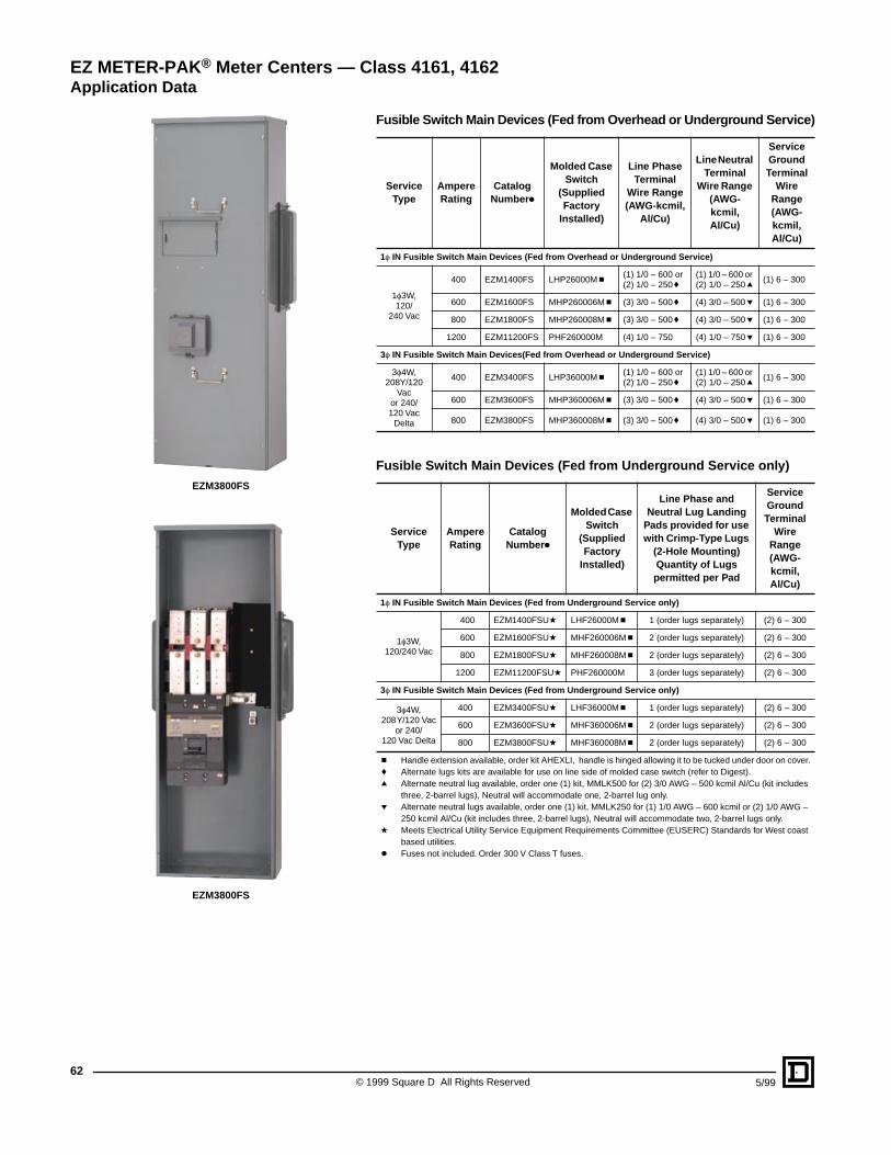
© 1999 Square D All Rights Reserved62
5/99
Fusible Switch Main Devices (Fed from Overhead or Underground Service)
Fusible Switch Main Devices (Fed from Underground Service only)
Service Type
AmpereRating
Catalog Number k
Molded Case Switch
(Supplied Factory
Installed)
Line Phase Terminal
Wire Range (AWG-kcmil,
Al/Cu)
Line Neutral Terminal
Wire Range (AWG-kcmil, Al/Cu)
Service Ground Terminal
Wire Range (AWG-kcmil, Al/Cu)
1f IN Fusible Switch Main Devices (Fed from Overhead or Underground Service)
1f3W, 120/
240 Vac
400 EZM1400FS LHP26000M c(1) 1/0 – 600 or (2) 1/0 – 250 f
(1) 1/0 – 600 or (2) 1/0 – 250 q
(1) 6 – 300
600 EZM1600FS MHP260006M c (3) 3/0 – 500 f (4) 3/0 – 500 p (1) 6 – 300
800 EZM1800FS MHP260008M c (3) 3/0 – 500 f (4) 3/0 – 500 p (1) 6 – 300
1200 EZM11200FS PHF260000M (4) 1/0 – 750 (4) 1/0 – 750 p (1) 6 – 300
3f IN Fusible Switch Main Devices(Fed from Overhead or Underground Service)
3f4W, 208Y/120
Vacor 240/120 Vac
Delta
400 EZM3400FS LHP36000M c(1) 1/0 – 600 or (2) 1/0 – 250 f
(1) 1/0 – 600 or (2) 1/0 – 250 q
(1) 6 – 300
600 EZM3600FS MHP360006M c (3) 3/0 – 500 f (4) 3/0 – 500 p (1) 6 – 300
800 EZM3800FS MHP360008M c (3) 3/0 – 500 f (4) 3/0 – 500 p (1) 6 – 300
Service Type
Ampere Rating
Catalog Number k
Molded Case Switch
(Supplied Factory
Installed)
Line Phase and Neutral Lug Landing
Pads provided for use with Crimp-Type Lugs
(2-Hole Mounting) Quantity of Lugs permitted per Pad
Service Ground Terminal
Wire Range (AWG-kcmil,Al/Cu)
1f IN Fusible Switch Main Devices (Fed from Underground Service only)
1f3W, 120/240 Vac
400 EZM1400FSUa LHF26000M c 1 (order lugs separately) (2) 6 – 300
600 EZM1600FSUa MHF260006M c 2 (order lugs separately) (2) 6 – 300
800 EZM1800FSUa MHF260008M c 2 (order lugs separately) (2) 6 – 300
1200 EZM11200FSUa PHF260000M 3 (order lugs separately) (2) 6 – 300
3f IN Fusible Switch Main Devices (Fed from Underground Service only)
3f4W, 208Y/120 Vac
or 240/120 Vac Delta
400 EZM3400FSUa LHF36000M c 1 (order lugs separately) (2) 6 – 300
600 EZM3600FSUa MHF360006M c 2 (order lugs separately) (2) 6 – 300
800 EZM3800FSUa MHF360008M c 2 (order lugs separately) (2) 6 – 300
c Handle extension available, order kit AHEXLI, handle is hinged allowing it to be tucked under door on cover.f Alternate lugs kits are available for use on line side of molded case switch (refer to Digest).q Alternate neutral lug available, order one (1) kit, MMLK500 for (2) 3/0 AWG – 500 kcmil Al/Cu (kit includes
three, 2-barrel lugs), Neutral will accommodate one, 2-barrel lug only.p Alternate neutral lugs available, order one (1) kit, MMLK250 for (1) 1/0 AWG – 600 kcmil or (2) 1/0 AWG –
250 kcmil Al/Cu (kit includes three, 2-barrel lugs), Neutral will accommodate two, 2-barrel lugs only.a Meets Electrical Utility Service Equipment Requirements Committee (EUSERC) Standards for West coast
based utilities.k Fuses not included. Order 300 V Class T fuses.
EZ METER-PAK® Meter Centers — Class 4161, 4162Application Data
EZM3800FS
EZM3800FS
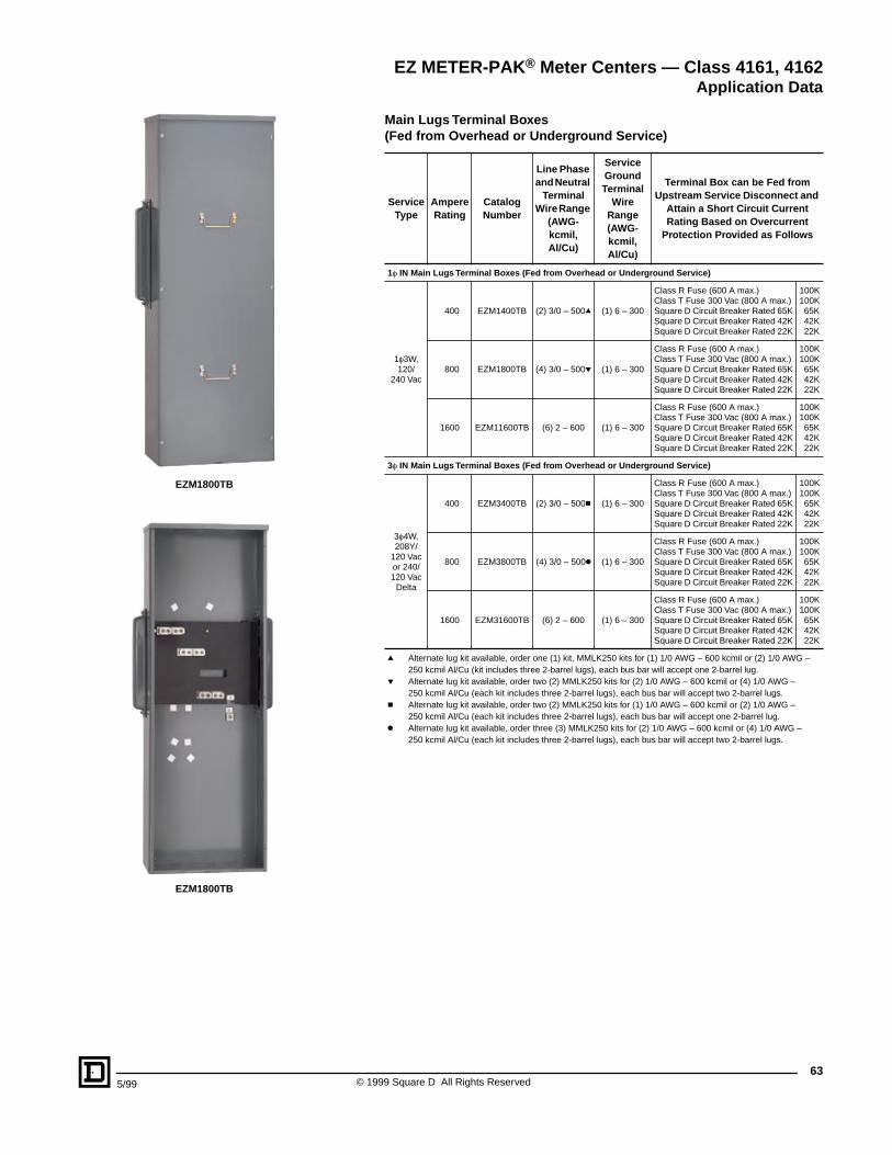
635/99 © 1999 Square D All Rights Reserved
Main Lugs Terminal Boxes(Fed from Overhead or Underground Service)
Service Type
AmpereRating
Catalog Number
Line Phase and Neutral
Terminal Wire Range
(AWG-kcmil, Al/Cu)
Service Ground Terminal
Wire Range (AWG-kcmil, Al/Cu)
Terminal Box can be Fed from Upstream Service Disconnect and
Attain a Short Circuit Current Rating Based on Overcurrent
Protection Provided as Follows
1f IN Main Lugs Terminal Boxes (Fed from Overhead or Underground Service)
1f3W, 120/
240 Vac
400 EZM1400TB (2) 3/0 – 500q (1) 6 – 300
Class R Fuse (600 A max.)Class T Fuse 300 Vac (800 A max.)Square D Circuit Breaker Rated 65KSquare D Circuit Breaker Rated 42KSquare D Circuit Breaker Rated 22K
100K100K65K42K22K
800 EZM1800TB (4) 3/0 – 500p (1) 6 – 300
Class R Fuse (600 A max.)Class T Fuse 300 Vac (800 A max.)Square D Circuit Breaker Rated 65KSquare D Circuit Breaker Rated 42KSquare D Circuit Breaker Rated 22K
100K100K65K42K22K
1600 EZM11600TB (6) 2 – 600 (1) 6 – 300
Class R Fuse (600 A max.)Class T Fuse 300 Vac (800 A max.)Square D Circuit Breaker Rated 65KSquare D Circuit Breaker Rated 42KSquare D Circuit Breaker Rated 22K
100K100K65K42K22K
3f IN Main Lugs Terminal Boxes (Fed from Overhead or Underground Service)
3f4W, 208Y/
120 Vac or 240/120 Vac
Delta
400 EZM3400TB (2) 3/0 – 500c (1) 6 – 300
Class R Fuse (600 A max.)Class T Fuse 300 Vac (800 A max.)Square D Circuit Breaker Rated 65KSquare D Circuit Breaker Rated 42KSquare D Circuit Breaker Rated 22K
100K100K65K42K22K
800 EZM3800TB (4) 3/0 – 500k (1) 6 – 300
Class R Fuse (600 A max.)Class T Fuse 300 Vac (800 A max.)Square D Circuit Breaker Rated 65KSquare D Circuit Breaker Rated 42KSquare D Circuit Breaker Rated 22K
100K100K65K42K22K
1600 EZM31600TB (6) 2 – 600 (1) 6 – 300
Class R Fuse (600 A max.)Class T Fuse 300 Vac (800 A max.)Square D Circuit Breaker Rated 65KSquare D Circuit Breaker Rated 42KSquare D Circuit Breaker Rated 22K
100K100K65K42K22K
q Alternate lug kit available, order one (1) kit, MMLK250 kits for (1) 1/0 AWG – 600 kcmil or (2) 1/0 AWG – 250 kcmil Al/Cu (kit includes three 2-barrel lugs), each bus bar will accept one 2-barrel lug.
p Alternate lug kit available, order two (2) MMLK250 kits for (2) 1/0 AWG – 600 kcmil or (4) 1/0 AWG – 250 kcmil Al/Cu (each kit includes three 2-barrel lugs), each bus bar will accept two 2-barrel lugs.
c Alternate lug kit available, order two (2) MMLK250 kits for (1) 1/0 AWG – 600 kcmil or (2) 1/0 AWG – 250 kcmil Al/Cu (each kit includes three 2-barrel lugs), each bus bar will accept one 2-barrel lug.
k Alternate lug kit available, order three (3) MMLK250 kits for (2) 1/0 AWG – 600 kcmil or (4) 1/0 AWG – 250 kcmil Al/Cu (each kit includes three 2-barrel lugs), each bus bar will accept two 2-barrel lugs.
EZ METER-PAK® Meter Centers — Class 4161, 4162Application Data
EZM1800TB
EZM1800TB
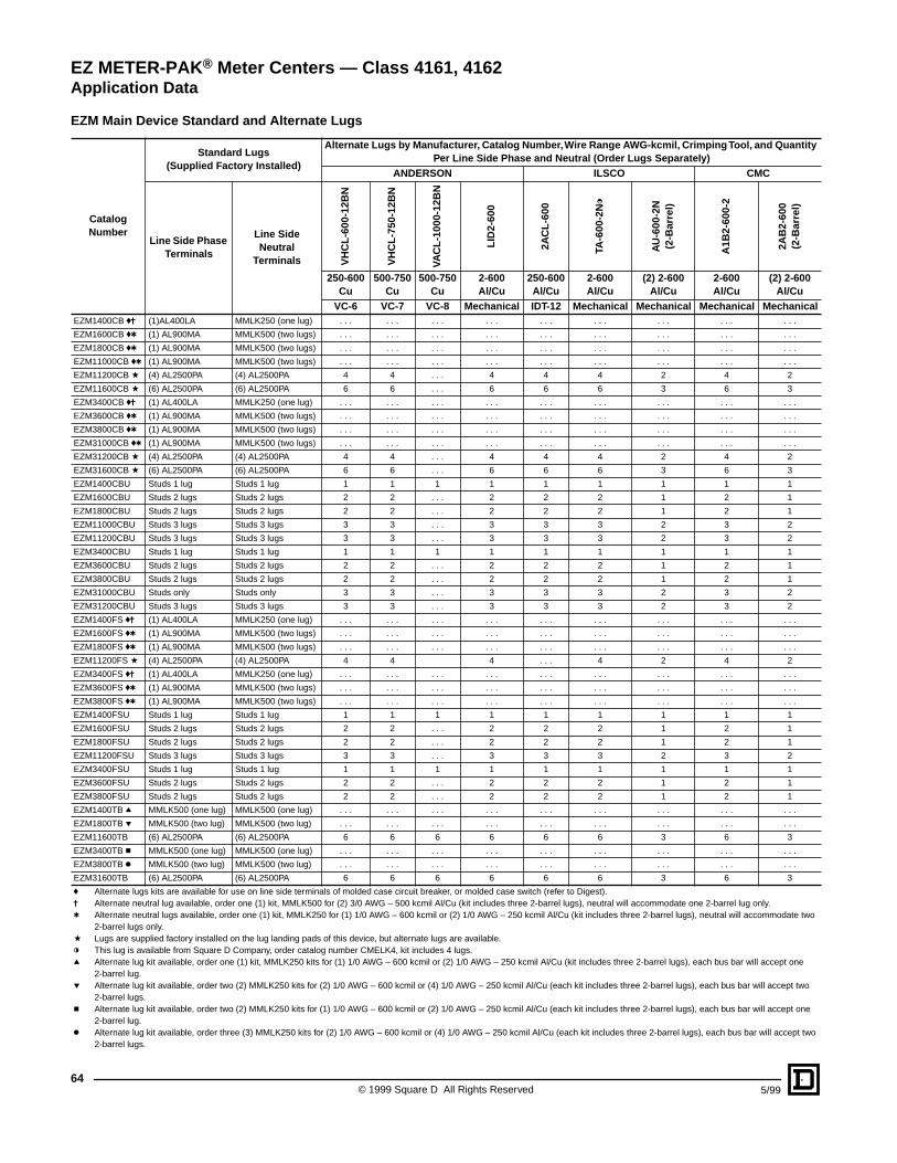
© 1999 Square D All Rights Reserved64
5/99
EZM Main Device Standard and Alternate Lugs
Catalog Number
Standard Lugs (Supplied Factory Installed)
Alternate Lugs by Manufacturer, Catalog Number, Wire Range AWG-kcmil, Crimping Tool, and Quantity Per Line Side Phase and Neutral (Order Lugs Separately)
ANDERSON ILSCO CMC
Line Side Phase Terminals
Line Side Neutral
Terminals VH
CL-
600-
12B
N
VH
CL-
750-
12B
N
VAC
L-10
00-1
2BN
LID
2-60
0
2AC
L-60
0
TA-6
00-2
Nl
AU
-600
-2N
(2-B
arre
l)
A1B
2-60
0-2
2AB
2-60
0(2
-Bar
rel)
250-600 Cu
500-750Cu
500-750Cu
2-600 Al/Cu
250-600Al/Cu
2-600 Al/Cu
(2) 2-600Al/Cu
2-600 Al/Cu
(2) 2-600Al/Cu
VC-6 VC-7 VC-8 Mechanical IDT-12 Mechanical Mechanical Mechanical MechanicalEZM1400CB fj (1)AL400LA MMLK250 (one lug) . . . . . . . . . . . . . . . . . . . . . . . . . . .
EZM1600CB ft (1) AL900MA MMLK500 (two lugs) . . . . . . . . . . . . . . . . . . . . . . . . . . .
EZM1800CB ft (1) AL900MA MMLK500 (two lugs) . . . . . . . . . . . . . . . . . . . . . . . . . . .
EZM11000CB ft (1) AL900MA MMLK500 (two lugs) . . . . . . . . . . . . . . . . . . . . . . . . . . .
EZM11200CB a (4) AL2500PA (4) AL2500PA 4 4 . . . 4 4 4 2 4 2
EZM11600CB a (6) AL2500PA (6) AL2500PA 6 6 . . . 6 6 6 3 6 3
EZM3400CB fj (1) AL400LA MMLK250 (one lug) . . . . . . . . . . . . . . . . . . . . . . . . . . .
EZM3600CB ft (1) AL900MA MMLK500 (two lugs) . . . . . . . . . . . . . . . . . . . . . . . . . . .
EZM3800CB ft (1) AL900MA MMLK500 (two lugs) . . . . . . . . . . . . . . . . . . . . . . . . . . .
EZM31000CB ft (1) AL900MA MMLK500 (two lugs) . . . . . . . . . . . . . . . . . . . . . . . . . . .
EZM31200CB a (4) AL2500PA (4) AL2500PA 4 4 . . . 4 4 4 2 4 2
EZM31600CB a (6) AL2500PA (6) AL2500PA 6 6 . . . 6 6 6 3 6 3
EZM1400CBU Studs 1 lug Studs 1 lug 1 1 1 1 1 1 1 1 1
EZM1600CBU Studs 2 lugs Studs 2 lugs 2 2 . . . 2 2 2 1 2 1
EZM1800CBU Studs 2 lugs Studs 2 lugs 2 2 . . . 2 2 2 1 2 1
EZM11000CBU Studs 3 lugs Studs 3 lugs 3 3 . . . 3 3 3 2 3 2
EZM11200CBU Studs 3 lugs Studs 3 lugs 3 3 . . . 3 3 3 2 3 2
EZM3400CBU Studs 1 lug Studs 1 lug 1 1 1 1 1 1 1 1 1
EZM3600CBU Studs 2 lugs Studs 2 lugs 2 2 . . . 2 2 2 1 2 1
EZM3800CBU Studs 2 lugs Studs 2 lugs 2 2 . . . 2 2 2 1 2 1
EZM31000CBU Studs only Studs only 3 3 . . . 3 3 3 2 3 2
EZM31200CBU Studs 3 lugs Studs 3 lugs 3 3 . . . 3 3 3 2 3 2
EZM1400FS fj (1) AL400LA MMLK250 (one lug) . . . . . . . . . . . . . . . . . . . . . . . . . . .
EZM1600FS ft (1) AL900MA MMLK500 (two lugs) . . . . . . . . . . . . . . . . . . . . . . . . . . .
EZM1800FS ft (1) AL900MA MMLK500 (two lugs) . . . . . . . . . . . . . . . . . . . . . . . . . . .
EZM11200FS a (4) AL2500PA (4) AL2500PA 4 4 4 . . . 4 2 4 2
EZM3400FS fj (1) AL400LA MMLK250 (one lug) . . . . . . . . . . . . . . . . . . . . . . . . . . .
EZM3600FS ft (1) AL900MA MMLK500 (two lugs) . . . . . . . . . . . . . . . . . . . . . . . . . . .
EZM3800FS ft (1) AL900MA MMLK500 (two lugs) . . . . . . . . . . . . . . . . . . . . . . . . . . .
EZM1400FSU Studs 1 lug Studs 1 lug 1 1 1 1 1 1 1 1 1
EZM1600FSU Studs 2 lugs Studs 2 lugs 2 2 . . . 2 2 2 1 2 1
EZM1800FSU Studs 2 lugs Studs 2 lugs 2 2 . . . 2 2 2 1 2 1
EZM11200FSU Studs 3 lugs Studs 3 lugs 3 3 . . . 3 3 3 2 3 2
EZM3400FSU Studs 1 lug Studs 1 lug 1 1 1 1 1 1 1 1 1
EZM3600FSU Studs 2 lugs Studs 2 lugs 2 2 . . . 2 2 2 1 2 1
EZM3800FSU Studs 2 lugs Studs 2 lugs 2 2 . . . 2 2 2 1 2 1
EZM1400TB q MMLK500 (one lug) MMLK500 (one lug) . . . . . . . . . . . . . . . . . . . . . . . . . . .
EZM1800TB p MMLK500 (two lug) MMLK500 (two lug) . . . . . . . . . . . . . . . . . . . . . . . . . . .
EZM11600TB (6) AL2500PA (6) AL2500PA 6 6 6 6 6 6 3 6 3
EZM3400TB c MMLK500 (one lug) MMLK500 (one lug) . . . . . . . . . . . . . . . . . . . . . . . . . . .
EZM3800TB k MMLK500 (two lug) MMLK500 (two lug) . . . . . . . . . . . . . . . . . . . . . . . . . . .
EZM31600TB (6) AL2500PA (6) AL2500PA 6 6 6 6 6 6 3 6 3
f Alternate lugs kits are available for use on line side terminals of molded case circuit breaker, or molded case switch (refer to Digest).j Alternate neutral lug available, order one (1) kit, MMLK500 for (2) 3/0 AWG – 500 kcmil Al/Cu (kit includes three 2-barrel lugs), neutral will accommodate one 2-barrel lug only.t Alternate neutral lugs available, order one (1) kit, MMLK250 for (1) 1/0 AWG – 600 kcmil or (2) 1/0 AWG – 250 kcmil Al/Cu (kit includes three 2-barrel lugs), neutral will accommodate two
2-barrel lugs only.a Lugs are supplied factory installed on the lug landing pads of this device, but alternate lugs are available.l This lug is available from Square D Company, order catalog number CMELK4, kit includes 4 lugs.q Alternate lug kit available, order one (1) kit, MMLK250 kits for (1) 1/0 AWG – 600 kcmil or (2) 1/0 AWG – 250 kcmil Al/Cu (kit includes three 2-barrel lugs), each bus bar will accept one
2-barrel lug.p Alternate lug kit available, order two (2) MMLK250 kits for (2) 1/0 AWG – 600 kcmil or (4) 1/0 AWG – 250 kcmil Al/Cu (each kit includes three 2-barrel lugs), each bus bar will accept two
2-barrel lugs.c Alternate lug kit available, order two (2) MMLK250 kits for (1) 1/0 AWG – 600 kcmil or (2) 1/0 AWG – 250 kcmil Al/Cu (each kit includes three 2-barrel lugs), each bus bar will accept one
2-barrel lug.k Alternate lug kit available, order three (3) MMLK250 kits for (2) 1/0 AWG – 600 kcmil or (4) 1/0 AWG – 250 kcmil Al/Cu (each kit includes three 2-barrel lugs), each bus bar will accept two
2-barrel lugs.
EZ METER-PAK® Meter Centers — Class 4161, 4162Application Data
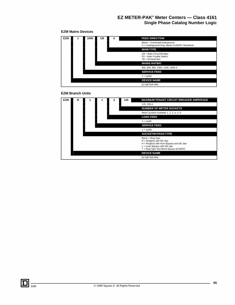
655/99 © 1999 Square D All Rights Reserved
EZM Mains Devices
EZM Branch Units
EZM 1 1000 CB U FEED DIRECTION
Blank = Overhead/UndergroundU = Underground Only, Meets EUSERC Standards
MAIN TYPE
CB = Main Circuit BreakerFS = Main Fusible SwitchTB = Terminal Box
MAINS RATING
400, 600, 800, 1000, 1200, 1600 A
SERVICE FEED
1 = 1f3W
DEVICE NAME
EZ METER-PAK
EZM R 1 1 3 125 MAXIMUM TENANT CIRCUIT BREAKER AMPERAGE
125, 200 A
NUMBER OF METER SOCKETS
Meter Sockets Available 1, 2, 3, 4, 5, 6
LOAD FEED
1 = 1f3W
SERVICE FEED
1 = 1f3W
SOCKET/BYPASS TYPE
Blank = Ring TypeR = Ringless with 5th JawH = Ringless with Horn Bypass and 5th JawL = Lever Bypass with 5th JawT = Ring Type Test-Block Bypass EUSERC
DEVICE NAME
EZ METER-PAK
EZ METER-PAK ® Meter Centers — Class 4161Single Phase Catalog Number Logic
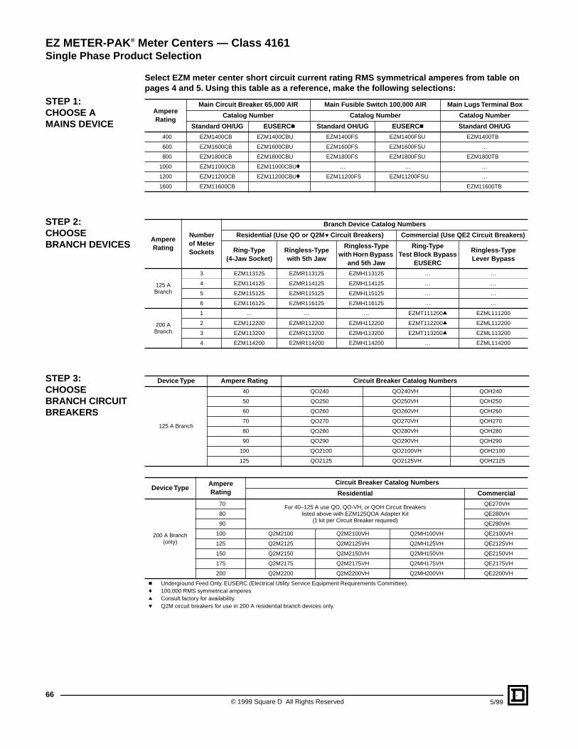
© 1999 Square D All Rights Reserved66
5/99
Select EZM meter center short circuit current rating RMS symmetrical amperes from table on pages 4 and 5. Using this table as a reference, make the following selections:
Ampere Rating
Main Circuit Breaker 65,000 AIR Main Fusible Switch 100,000 AIR Main Lugs Terminal Box
Catalog Number Catalog Number Catalog Number
Standard OH/UG EUSERC c Standard OH/UG EUSERC c Standard OH/UG
400 EZM1400CB EZM1400CBU EZM1400FS EZM1400FSU EZM1400TB
600 EZM1600CB EZM1600CBU EZM1600FS EZM1600FSU …
800 EZM1800CB EZM1800CBU EZM1800FS EZM1800FSU EZM1800TB
1000 EZM11000CB EZM11000CBUf … … …
1200 EZM11200CB EZM11200CBUf EZM11200FS EZM11200FSU …
1600 EZM11600CB EZM11600TB
Ampere Rating
Number of Meter Sockets
Branch Device Catalog Numbers
Residential (Use QO or Q2M p Circuit Breakers) Commercial (Use QE2 Circuit Breakers)
Ring-Type (4-Jaw Socket)
Ringless-Type with 5th Jaw
Ringless-Type with Horn Bypass
and 5th Jaw
Ring-Type Test Block Bypass
EUSERC
Ringless-Type Lever Bypass
125 A Branch
3 EZM113125 EZMR113125 EZMH113125 … …
4 EZM114125 EZMR114125 EZMH114125 … …
5 EZM115125 EZMR115125 EZMH115125 … …
6 EZM116125 EZMR116125 EZMH116125 … …
200 A Branch
1 … … … EZMT111200q EZML111200
2 EZM112200 EZMR112200 EZMH112200 EZMT112200q EZML112200
3 EZM113200 EZMR113200 EZMH113200 EZMT113200q EZML113200
4 EZM114200 EZMR114200 EZMH114200 … EZML114200
Device Type Ampere Rating Circuit Breaker Catalog Numbers
125 A Branch
40 QO240 QO240VH QOH240
50 QO250 QO250VH QOH250
60 QO260 QO260VH QOH260
70 QO270 QO270VH QOH270
80 QO280 QO280VH QOH280
90 QO290 QO290VH QOH290
100 QO2100 QO2100VH QOH2100
125 QO2125 QO2125VH QOH2125
Device TypeAmpere Rating
Circuit Breaker Catalog Numbers
Residential Commercial
200 A Branch(only)
70For 40–125 A use QO, QO-VH, or QOH Circuit Breakers
listed above with EZM125QOA Adapter Kit(1 kit per Circuit Breaker required)
QE270VH
80 QE280VH
90 QE290VH
100 Q2M2100 Q2M2100VH Q2MH100VH QE2100VH
125 Q2M2125 Q2M2125VH Q2MH125VH QE2125VH
150 Q2M2150 Q2M2150VH Q2MH150VH QE2150VH
175 Q2M2175 Q2M2175VH Q2MH175VH QE2175VH
200 Q2M2200 Q2M2200VH Q2MH200VH QE2200VH
c Underground Feed Only. EUSERC (Electrical Utility Service Equipment Requirements Committee).f 100,000 RMS symmetrical amperesq Consult factory for availability.p Q2M circuit breakers for use in 200 A residential branch devices only.
STEP 1: CHOOSE A MAINS DEVICE
STEP 2: CHOOSE BRANCH DEVICES
STEP 3:CHOOSEBRANCH CIRCUIT BREAKERS
EZ METER-PAK ® Meter Centers — Class 4161Single Phase Product Selection
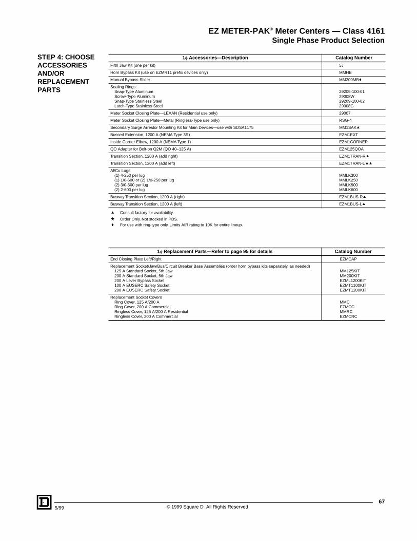
675/99 © 1999 Square D All Rights Reserved
1f Accessories—Description Catalog Number
Fifth Jaw Kit (one per kit) 5J
Horn Bypass Kit (use on EZMR11 prefix devices only) MMHB
Manual Bypass-Slider MM200MBf
Sealing Rings:Snap-Type AluminumScrew-Type AluminumSnap-Type Stainless SteelLatch-Type Stainless Steel
29209-100-0129008W29209-100-0229008G
Meter Socket Closing Plate—LEXAN (Residential use only) 29007
Meter Socket Closing Plate—Metal (Ringless-Type use only) RSG-4
Secondary Surge Arrestor Mounting Kit for Main Devices—use with SDSA1175 MM1SAKq
Bussed Extension, 1200 A (NEMA Type 3R) EZM1EXT
Inside Corner Elbow, 1200 A (NEMA Type 1) EZM1CORNER
QO Adapter for Bolt-on Q2M (QO 40–125 A) EZM125QOA
Transition Section, 1200 A (add right) EZM1TRAN-R q
Transition Section, 1200 A (add left) EZM1TRAN-Laq
Al/Cu Lugs(1) 4-250 per lug(1) 1/0-600 or (2) 1/0-250 per lug(2) 3/0-500 per lug(2) 2-600 per lug
MMLK300MMLK250MMLK500MMLK600
Busway Transition Section, 1200 A (right) EZM1BUS-Rq
Busway Transition Section, 1200 A (left) EZM1BUS-Lq
q Consult factory for availability.
a Order Only. Not stocked in PDS.f For use with ring-type only. Limits AIR rating to 10K for entire lineup.
1f Replacement Parts—Refer to page 95 for details Catalog Number
End Closing Plate Left/Right EZMCAP
Replacement Socket/Jaw/Bus/Circuit Breaker Base Assemblies (order horn bypass kits separately, as needed)125 A Standard Socket, 5th Jaw200 A Standard Socket, 5th Jaw200 A Lever Bypass Socket100 A EUSERC Safety Socket200 A EUSERC Safety Socket
MM125KITMM200KITEZML1200KITEZMT1100KITEZMT1200KIT
Replacement Socket CoversRing Cover, 125 A/200 ARing Cover, 200 A CommercialRingless Cover, 125 A/200 A ResidentialRingless Cover, 200 A Commercial
MMCEZMCCMMRCEZMCRC
STEP 4: CHOOSEACCESSORIES AND/OR REPLACEMENT PARTS
EZ METER-PAK ® Meter Centers — Class 4161Single Phase Product Selection
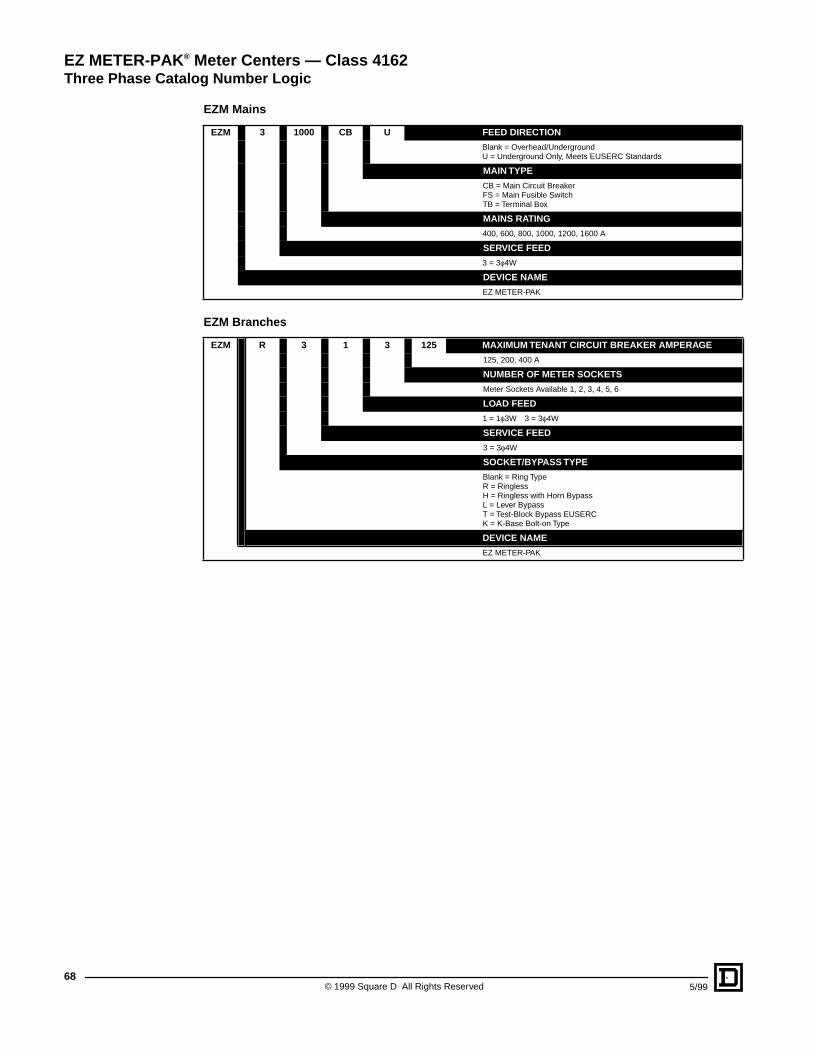
© 1999 Square D All Rights Reserved68
5/99
EZM Mains
EZM Branches
EZM 3 1000 CB U FEED DIRECTION
Blank = Overhead/UndergroundU = Underground Only, Meets EUSERC Standards
MAIN TYPE
CB = Main Circuit BreakerFS = Main Fusible SwitchTB = Terminal Box
MAINS RATING
400, 600, 800, 1000, 1200, 1600 A
SERVICE FEED
3 = 3f4W
DEVICE NAME
EZ METER-PAK
EZM R 3 1 3 125 MAXIMUM TENANT CIRCUIT BREAKER AMPERAGE
125, 200, 400 A
NUMBER OF METER SOCKETS
Meter Sockets Available 1, 2, 3, 4, 5, 6
LOAD FEED
1 = 1f3W 3 = 3f4W
SERVICE FEED
3 = 3f4W
SOCKET/BYPASS TYPE
Blank = Ring TypeR = RinglessH = Ringless with Horn BypassL = Lever BypassT = Test-Block Bypass EUSERCK = K-Base Bolt-on Type
DEVICE NAME
EZ METER-PAK
EZ METER-PAK ® Meter Centers — Class 4162Three Phase Catalog Number Logic
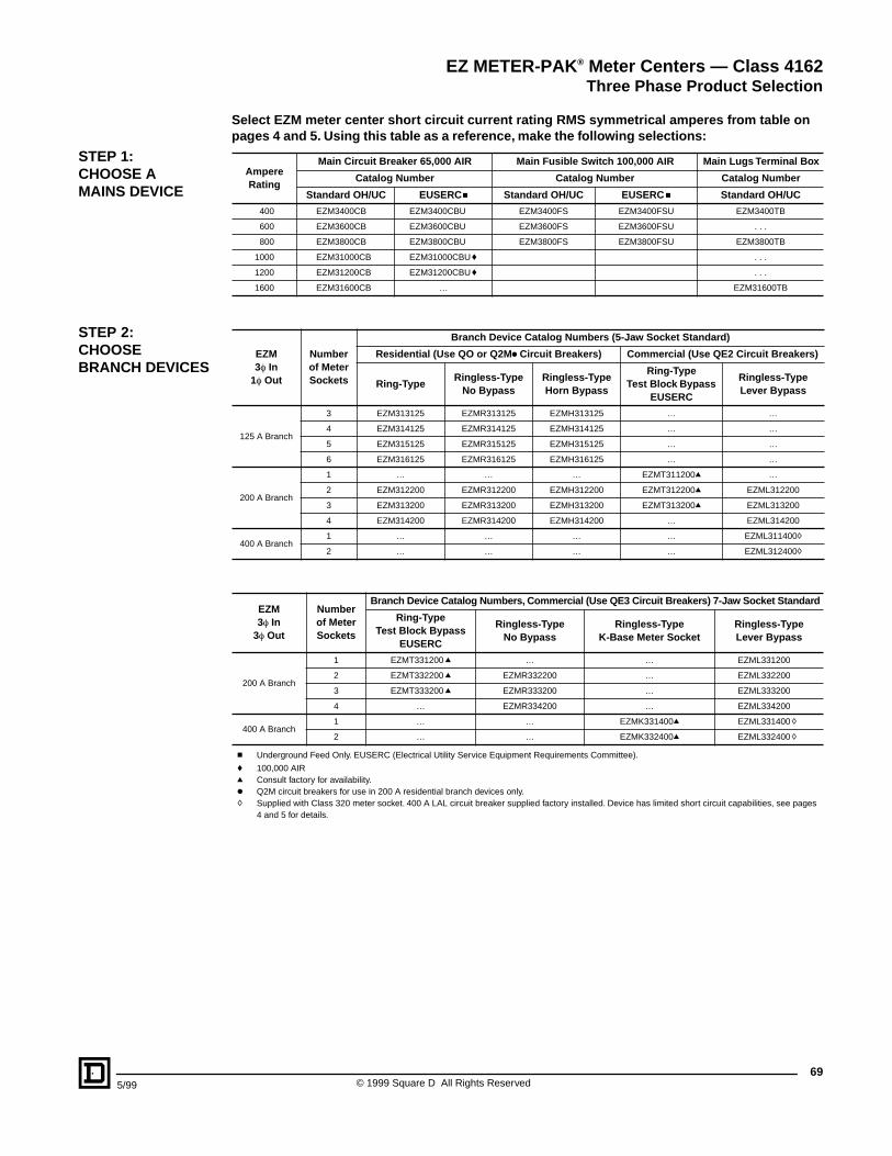
695/99 © 1999 Square D All Rights Reserved
Select EZM meter center short circuit current rating RMS symmetrical amperes from table on pages 4 and 5. Using this table as a reference, make the following selections:
Ampere Rating
Main Circuit Breaker 65,000 AIR Main Fusible Switch 100,000 AIR Main Lugs Terminal Box
Catalog Number Catalog Number Catalog Number
Standard OH/UC EUSERC c Standard OH/UC EUSERC c Standard OH/UC
400 EZM3400CB EZM3400CBU EZM3400FS EZM3400FSU EZM3400TB
600 EZM3600CB EZM3600CBU EZM3600FS EZM3600FSU . . .
800 EZM3800CB EZM3800CBU EZM3800FS EZM3800FSU EZM3800TB
1000 EZM31000CB EZM31000CBU f . . .
1200 EZM31200CB EZM31200CBU f . . .
1600 EZM31600CB … EZM31600TB
EZM3f In
1f Out
Number of Meter Sockets
Branch Device Catalog Numbers (5-Jaw Socket Standard)
Residential (Use QO or Q2M k Circuit Breakers) Commercial (Use QE2 Circuit Breakers)
Ring-TypeRingless-Type
No BypassRingless-Type Horn Bypass
Ring-Type Test Block Bypass
EUSERC
Ringless-Type Lever Bypass
125 A Branch
3 EZM313125 EZMR313125 EZMH313125 … …
4 EZM314125 EZMR314125 EZMH314125 … …
5 EZM315125 EZMR315125 EZMH315125 … …
6 EZM316125 EZMR316125 EZMH316125 … …
200 A Branch
1 … … … EZMT311200q …
2 EZM312200 EZMR312200 EZMH312200 EZMT312200q EZML312200
3 EZM313200 EZMR313200 EZMH313200 EZMT313200q EZML313200
4 EZM314200 EZMR314200 EZMH314200 … EZML314200
400 A Branch1 … … … … EZML311400h
2 … … … … EZML312400h
EZM3f In
3f Out
Number of Meter Sockets
Branch Device Catalog Numbers, Commercial (Use QE3 Circuit Breakers) 7-Jaw Socket Standard
Ring-Type Test Block Bypass
EUSERC
Ringless-Type No Bypass
Ringless-TypeK-Base Meter Socket
Ringless-TypeLever Bypass
200 A Branch
1 EZMT331200 q … … EZML331200
2 EZMT332200 q EZMR332200 … EZML332200
3 EZMT333200 q EZMR333200 … EZML333200
4 … EZMR334200 … EZML334200
400 A Branch1 … … EZMK331400q EZML331400 h
2 … … EZMK332400q EZML332400 h
c Underground Feed Only. EUSERC (Electrical Utility Service Equipment Requirements Committee).
f 100,000 AIRq Consult factory for availability.k Q2M circuit breakers for use in 200 A residential branch devices only.h Supplied with Class 320 meter socket. 400 A LAL circuit breaker supplied factory installed. Device has limited short circuit capabilities, see pages
4 and 5 for details.
STEP 1: CHOOSE A MAINS DEVICE
STEP 2: CHOOSE BRANCH DEVICES
EZ METER-PAK ® Meter Centers — Class 4162Three Phase Product Selection
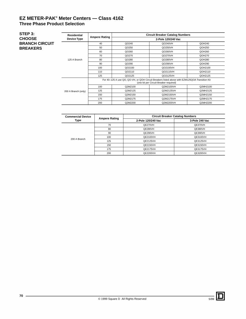
© 1999 Square D All Rights Reserved70
5/99
ResidentialDevice Type
Ampere RatingCircuit Breaker Catalog Numbers
2-Pole 120/240 Vac
125 A Branch
40 QO240 QO240VH QOH240
50 QO250 QO250VH QOH250
60 QO260 QO260VH QOH260
70 QO270 QO270VH QOH270
80 QO280 QO280VH QOH280
90 QO290 QO290VH QOH290
100 QO2100 QO2100VH QOH2100
110 QO2110 QO2110VH QOH2110
125 QO2125 QO2125VH QOH2125
200 A Branch (only)
For 40–125 A use QO, QO-VH, or QOH Circuit Breakers listed above with EZM125QOA Transition Kit (one kit per Circuit Breaker required)
100 Q2M2100 Q2M2100VH Q2MH2100
125 Q2M2125 Q2M2125VH Q2MH2125
150 Q2M2150 Q2M2150VH Q2MH2150
175 Q2M2175 Q2M2175VH Q2MH2175
200 Q2M2200 Q2M2200VH Q2MH2200
Commercial Device Type
Ampere RatingCircuit Breaker Catalog Numbers
2-Pole 120/240 Vac 3-Pole 240 Vac
200 A Branch
70 QE270VH QE370VH
80 QE280VH QE380VH
90 QE290VH QE390VH
100 QE2100VH QE3100VH
125 QE2125VH QE3125VH
150 QE2150VH QE3150VH
175 QE2175VH QE3175VH
200 QE2200VH QE3200VH
STEP 3:CHOOSE BRANCH CIRCUIT BREAKERS
EZ METER-PAK ® Meter Centers — Class 4162Three Phase Product Selection
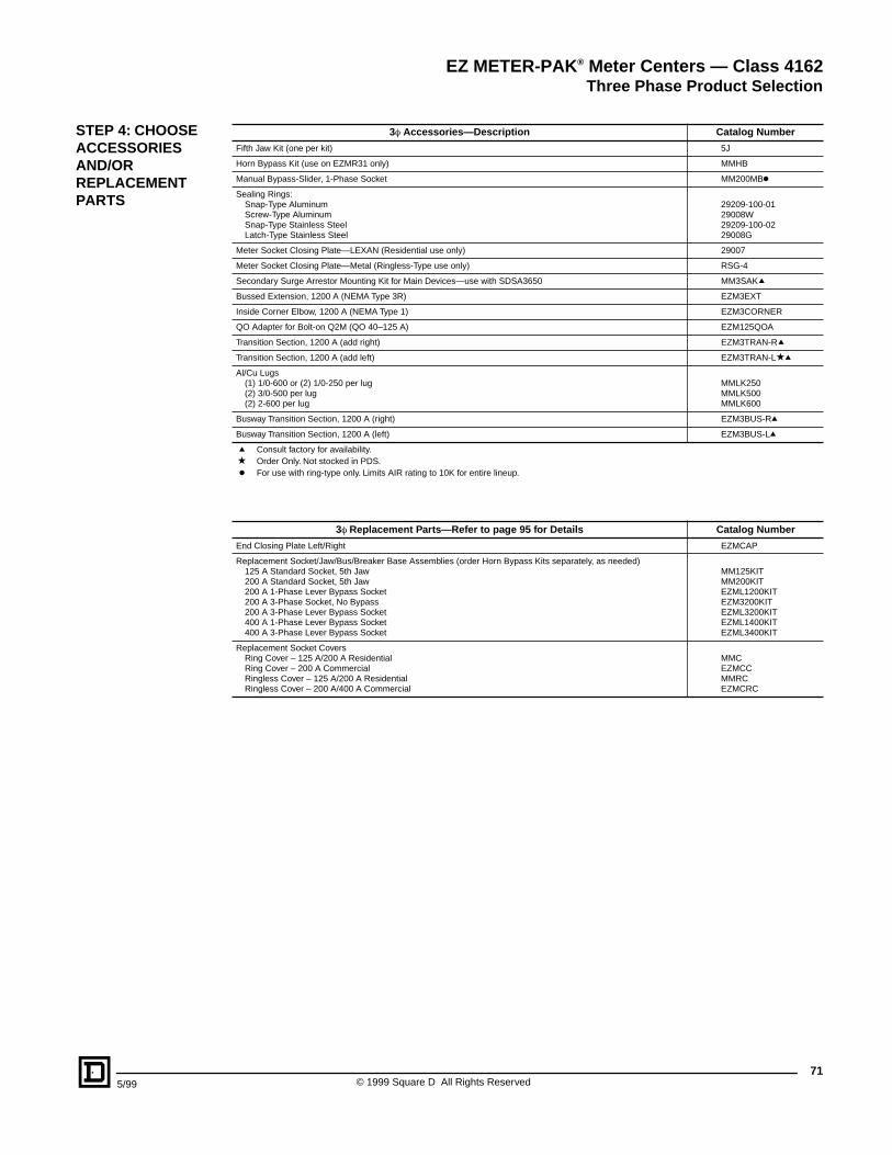
715/99 © 1999 Square D All Rights Reserved
3f Accessories—Description Catalog Number
Fifth Jaw Kit (one per kit) 5J
Horn Bypass Kit (use on EZMR31 only) MMHB
Manual Bypass-Slider, 1-Phase Socket MM200MBk
Sealing Rings:Snap-Type AluminumScrew-Type AluminumSnap-Type Stainless SteelLatch-Type Stainless Steel
29209-100-0129008W29209-100-0229008G
Meter Socket Closing Plate—LEXAN (Residential use only) 29007
Meter Socket Closing Plate—Metal (Ringless-Type use only) RSG-4
Secondary Surge Arrestor Mounting Kit for Main Devices—use with SDSA3650 MM3SAKq
Bussed Extension, 1200 A (NEMA Type 3R) EZM3EXT
Inside Corner Elbow, 1200 A (NEMA Type 1) EZM3CORNER
QO Adapter for Bolt-on Q2M (QO 40–125 A) EZM125QOA
Transition Section, 1200 A (add right) EZM3TRAN-Rq
Transition Section, 1200 A (add left) EZM3TRAN-Laq
Al/Cu Lugs(1) 1/0-600 or (2) 1/0-250 per lug(2) 3/0-500 per lug(2) 2-600 per lug
MMLK250MMLK500MMLK600
Busway Transition Section, 1200 A (right) EZM3BUS-Rq
Busway Transition Section, 1200 A (left) EZM3BUS-Lq
q Consult factory for availability.a Order Only. Not stocked in PDS.k For use with ring-type only. Limits AIR rating to 10K for entire lineup.
3f Replacement Parts—Refer to page 95 for Details Catalog Number
End Closing Plate Left/Right EZMCAP
Replacement Socket/Jaw/Bus/Breaker Base Assemblies (order Horn Bypass Kits separately, as needed)125 A Standard Socket, 5th Jaw200 A Standard Socket, 5th Jaw200 A 1-Phase Lever Bypass Socket200 A 3-Phase Socket, No Bypass200 A 3-Phase Lever Bypass Socket400 A 1-Phase Lever Bypass Socket400 A 3-Phase Lever Bypass Socket
MM125KITMM200KITEZML1200KITEZM3200KITEZML3200KITEZML1400KITEZML3400KIT
Replacement Socket CoversRing Cover – 125 A/200 A ResidentialRing Cover – 200 A CommercialRingless Cover – 125 A/200 A ResidentialRingless Cover – 200 A/400 A Commercial
MMCEZMCCMMRCEZMCRC
STEP 4: CHOOSE ACCESSORIES AND/OR REPLACEMENT PARTS
EZ METER-PAK ® Meter Centers — Class 4162Three Phase Product Selection
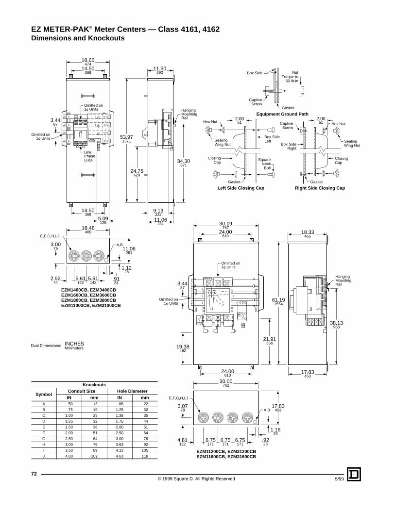
© 1999 Square D All Rights Reserved72
5/99
18.66474
14.50368
14.50368
11.50292
3.4487
53.971371
34.30871
11.06281
1.1228
.9123
18.48469
5.09129
9.13232
11.06281
5.61142
5.61142
2.9274
3.0076
A,B
E,F,G,H,I,J
HangingMountingRail
Omitted on1f Units
Omitted on1f Units
24.75629
EZM1400CB, EZM3400CBEZM1600CB, EZM3600CBEZM1800CB, EZM3800CBEZM11000CB, EZM31000CB
LinePhaseLugs
30.19767
3.4487
19.38492
21.91556
Omitted on1f Units
EZM11200CB, EZM31200CBEZM11600CB, EZM31600CB
18.33465
17.83453
61.191554
38.13968
HangingMountingRail
24.00610
24.00610
17.83453
30.00762
6.75171
.9223
1.1629
6.75171
6.75171
4.81122
3.0778
E,F,G,H,I,J
A,B
Omitted on1f Units
Knockouts
SymbolConduit Size Hole DiameterIN mm IN mm
A .50 13 .88 22
B .75 19 1.25 32
C 1.00 25 1.38 35
D 1.25 32 1.75 44
E 1.50 38 2.00 51
F 2.00 51 2.50 64
G 2.50 64 3.00 76
H 3.00 76 3.63 92
I 3.50 89 4.13 105
J 4.00 102 4.63 118
Box Side NutTorque to
50 lb-in
Gasket
Gasket Gasket
CaptiveScrew
2.0051
2.0051Hex Nut Hex NutCaptive
Screw
SealingWing Nut
SealingWing Nut
Box SideLeft
Box SideRight
SquareNeckBolt
ClosingCap
ClosingCap
Left Side Closing Cap
Equipment Ground Path
Right Side Closing Cap
EZ METER-PAK ® Meter Centers — Class 4161, 4162Dimensions and Knockouts
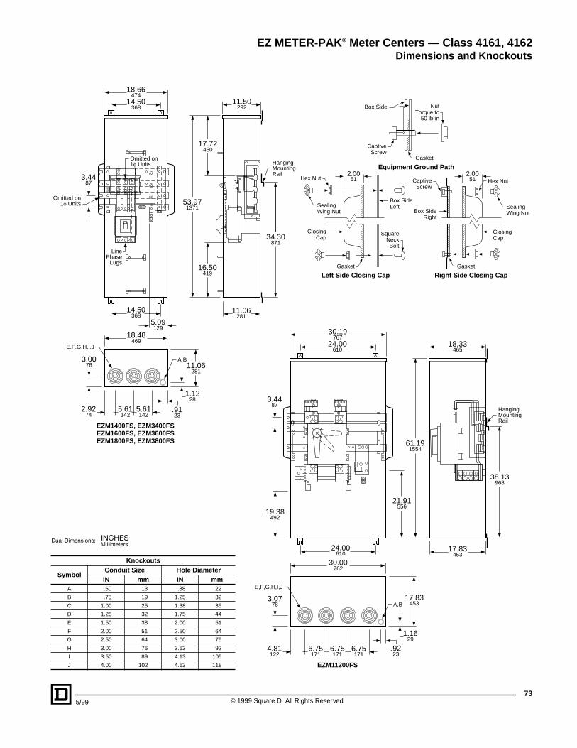
735/99 © 1999 Square D All Rights Reserved
18.66474
11.06281
11.50292
3.4487
53.971371
17.72450
34.30871
5.09129
HangingMountingRail
Omitted on1f Units
16.50419
EZM1400FS, EZM3400FSEZM1600FS, EZM3600FSEZM1800FS, EZM3800FS
Omitted on1f Units
LinePhase
Lugs
14.50368
14.50368
11.06281
1.1228
.9123
18.48469
5.61142
5.61142
2.9274
3.0076
A,B
E,F,G,H,I,J
3.4487
EZM11200FS
18.33465
17.83453
61.191554
38.13968
HangingMountingRail
30.19767
19.38492
21.91556
24.00610
24.00610
17.83453
30.00762
6.75171
.9223
1.1629
6.75171
6.75171
4.81122
3.0778
E,F,G,H,I,J
A,B
Knockouts
SymbolConduit Size Hole DiameterIN mm IN mm
A .50 13 .88 22
B .75 19 1.25 32
C 1.00 25 1.38 35
D 1.25 32 1.75 44
E 1.50 38 2.00 51
F 2.00 51 2.50 64
G 2.50 64 3.00 76
H 3.00 76 3.63 92
I 3.50 89 4.13 105
J 4.00 102 4.63 118
Box Side NutTorque to
50 lb-in
Gasket
Gasket Gasket
CaptiveScrew
2.0051
2.0051Hex Nut Hex NutCaptive
Screw
SealingWing Nut
SealingWing Nut
Box SideLeft
Box SideRight
SquareNeckBolt
ClosingCap
ClosingCap
Left Side Closing Cap
Equipment Ground Path
Right Side Closing Cap
EZ METER-PAK ® Meter Centers — Class 4161, 4162Dimensions and Knockouts
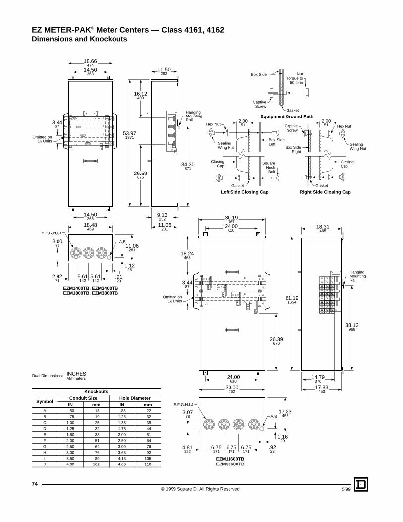
© 1999 Square D All Rights Reserved74
5/99
11.50292
3.4487
53.971371
26.59675
16.12409
34.30871
9.13232
HangingMountingRail
Omitted on1f Units
EZM1400TB, EZM3400TBEZM1800TB, EZM3800TB
11.06281
18.66474
14.50368
14.50368
11.06281
1.1228
.9123
18.48469
5.61142
5.61142
2.9274
3.0076
A,B
E,F,G,H,I,J
18.31465
3.4487
18.24463
26.39670
61.191554
38.12968
14.79376
HangingMountingRail
Omitted on1f Units
EZM11600TBEZM31600TB
17.83453
30.19767
24.00610
24.00610
17.83453
30.00762
6.75171
.9223
1.1629
6.75171
6.75171
4.81122
3.0778
E,F,G,H,I,J
A,B
Knockouts
SymbolConduit Size Hole DiameterIN mm IN mm
A .50 13 .88 22
B .75 19 1.25 32
C 1.00 25 1.38 35
D 1.25 32 1.75 44
E 1.50 38 2.00 51
F 2.00 51 2.50 64
G 2.50 64 3.00 76
H 3.00 76 3.63 92
I 3.50 89 4.13 105
J 4.00 102 4.63 118
Box Side NutTorque to
50 lb-in
Gasket
Gasket Gasket
CaptiveScrew
2.0051
2.0051Hex Nut Hex NutCaptive
Screw
SealingWing Nut
SealingWing Nut
Box SideLeft
Box SideRight
SquareNeckBolt
ClosingCap
ClosingCap
Left Side Closing Cap
Equipment Ground Path
Right Side Closing Cap
EZ METER-PAK ® Meter Centers — Class 4161, 4162Dimensions and Knockouts
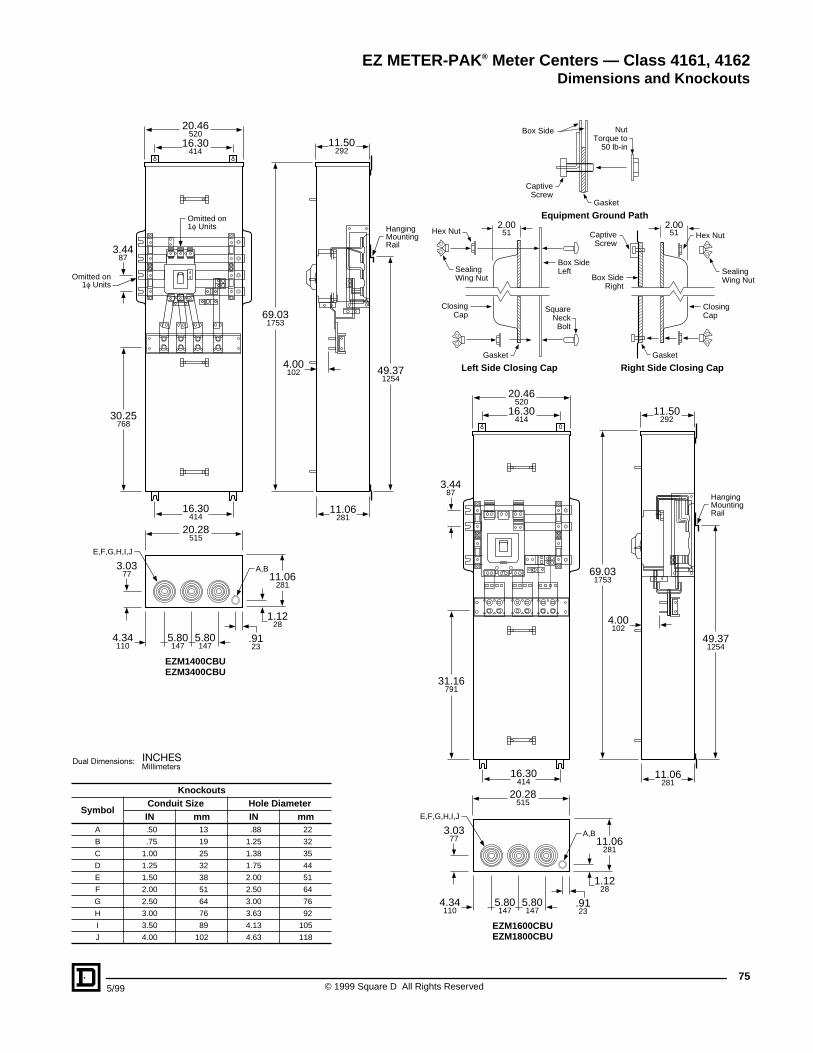
755/99 © 1999 Square D All Rights Reserved
20.46520
11.50292
3.4487
69.031753
49.371254
20.28515
11.06281
5.80147
5.80147
4.34110
30.25768
HangingMountingRail
EZM1400CBUEZM3400CBU
Omitted on1f Units
16.30414
16.30414
4.00102
E,F,G,H,I,J
11.06281
1.1228
.9123
A,B3.0377
Omitted on1f Units
11.50292
16.30414
69.031753
49.371254
4.00102
11.06281
HangingMountingRail
EZM1600CBUEZM1800CBU
3.4487
31.16791
16.30414
20.28515
5.80147
5.80147
4.34110
3.0377
E,F,G,H,I,J
11.06281
1.1228
.9123
A,B
20.46520
Knockouts
SymbolConduit Size Hole DiameterIN mm IN mm
A .50 13 .88 22
B .75 19 1.25 32
C 1.00 25 1.38 35
D 1.25 32 1.75 44
E 1.50 38 2.00 51
F 2.00 51 2.50 64
G 2.50 64 3.00 76
H 3.00 76 3.63 92
I 3.50 89 4.13 105
J 4.00 102 4.63 118
Box Side NutTorque to
50 lb-in
Gasket
Gasket Gasket
CaptiveScrew
2.0051
2.0051Hex Nut Hex NutCaptive
Screw
SealingWing Nut
SealingWing Nut
Box SideLeft
Box SideRight
SquareNeckBolt
ClosingCap
ClosingCap
Left Side Closing Cap
Equipment Ground Path
Right Side Closing Cap
EZ METER-PAK ® Meter Centers — Class 4161, 4162Dimensions and Knockouts
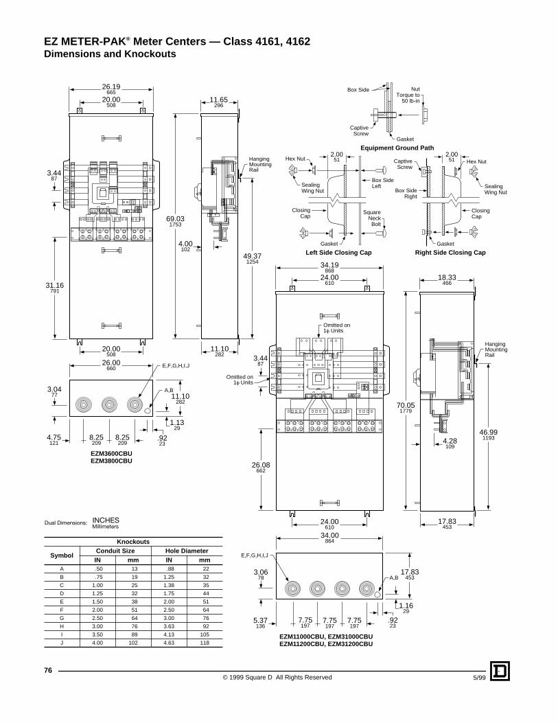
© 1999 Square D All Rights Reserved76
5/99
26.19665
20.00508
20.00508
11.65296
3.4487
69.031753
49.371254
11.10282
26.00660
11.10282
8.25209
8.25209
4.75121
3.0477
HangingMountingRail
EZM3600CBUEZM3800CBU
4.00102
31.16791
1.1329
.9223
A,B
E,F,G,H,I,J
34.19868
18.33466
24.00610
24.00610
3.4487
70.051779
46.991193
34.00864
17.83453
7.75197
7.75197
7.75197
5.37136
HangingMountingRail
Omitted on1f Units
EZM11000CBU, EZM31000CBUEZM11200CBU, EZM31200CBU
4.28109
26.08662
17.83453
1.1629
3.0678
E,F,G,H,I,J
A,B
.9223
Omitted on1f Units
Knockouts
SymbolConduit Size Hole DiameterIN mm IN mm
A .50 13 .88 22
B .75 19 1.25 32
C 1.00 25 1.38 35
D 1.25 32 1.75 44
E 1.50 38 2.00 51
F 2.00 51 2.50 64
G 2.50 64 3.00 76
H 3.00 76 3.63 92
I 3.50 89 4.13 105
J 4.00 102 4.63 118
Box Side NutTorque to
50 lb-in
Gasket
Gasket Gasket
CaptiveScrew
2.0051
2.0051Hex Nut Hex NutCaptive
Screw
SealingWing Nut
SealingWing Nut
Box SideLeft
Box SideRight
SquareNeckBolt
ClosingCap
ClosingCap
Left Side Closing Cap
Equipment Ground Path
Right Side Closing Cap
EZ METER-PAK ® Meter Centers — Class 4161, 4162Dimensions and Knockouts
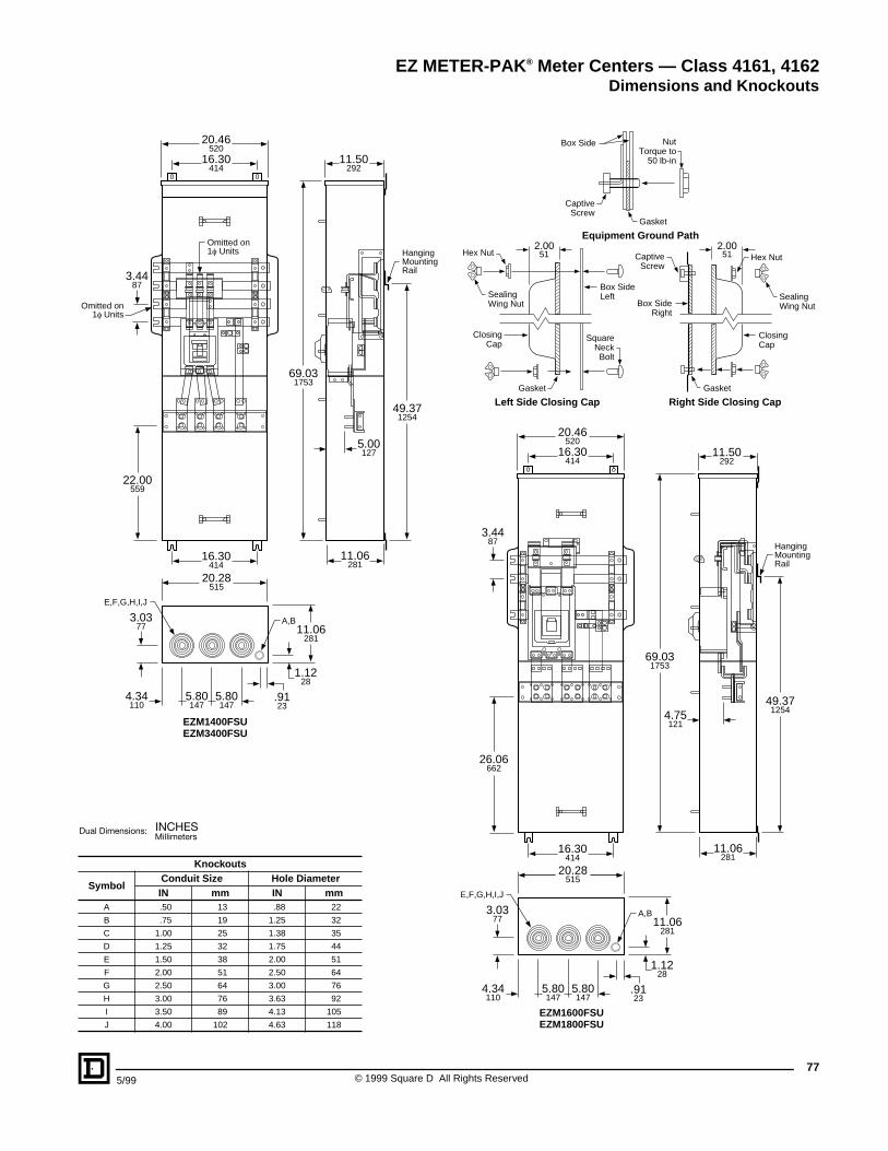
775/99 © 1999 Square D All Rights Reserved
20.46520
11.50292
16.30414
16.30414
3.4487
69.031753
49.371254
11.06281
22.00559
HangingMountingRail
EZM1400FSUEZM3400FSU
Omitted on1f Units
5.00127
20.28515
5.80147
5.80147
4.34110
E,F,G,H,I,J
11.06281
1.1228
.9123
A,B3.0377
Omitted on1f Units
11.50292
69.031753
49.371254
11.06281
HangingMountingRail
EZM1600FSUEZM1800FSU
3.4487
20.46520
16.30414
16.30414
26.06662
4.75121
20.28515
5.80147
5.80147
4.34110
E,F,G,H,I,J
11.06281
1.1228
.9123
A,B3.0377
Knockouts
SymbolConduit Size Hole DiameterIN mm IN mm
A .50 13 .88 22
B .75 19 1.25 32
C 1.00 25 1.38 35
D 1.25 32 1.75 44
E 1.50 38 2.00 51
F 2.00 51 2.50 64
G 2.50 64 3.00 76
H 3.00 76 3.63 92
I 3.50 89 4.13 105
J 4.00 102 4.63 118
Box Side NutTorque to
50 lb-in
Gasket
Gasket Gasket
CaptiveScrew
2.0051
2.0051Hex Nut Hex NutCaptive
Screw
SealingWing Nut
SealingWing Nut
Box SideLeft
Box SideRight
SquareNeckBolt
ClosingCap
ClosingCap
Left Side Closing Cap
Equipment Ground Path
Right Side Closing Cap
EZ METER-PAK ® Meter Centers — Class 4161, 4162Dimensions and Knockouts
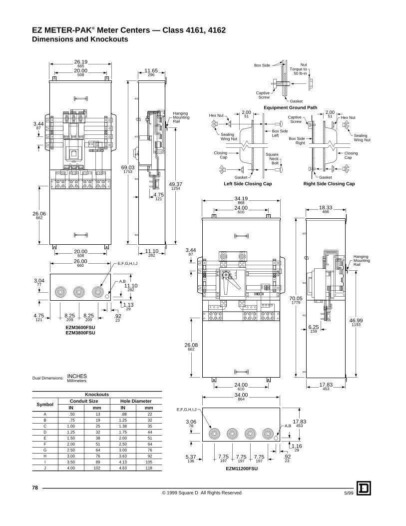
© 1999 Square D All Rights Reserved78
5/99
26.19665
11.65296
20.00508
20.00508
69.031753
49.371254
11.10282
HangingMountingRail
EZM3600FSUEZM3800FSU
3.4487
26.06662
4.75121
11.10282
26.00660
8.25209
8.25209
4.75121
3.0477
1.1329
.9223
A,B
E,F,G,H,I,J
34.19868
24.00610
24.00610
70.051779
46.991193
17.83453
26.08662
HangingMountingRail
EZM11200FSU
3.4487
6.25159
34.00864
18.33466
7.75197
7.75197
7.75197
5.37136
17.83453
1.1629
3.0678
E,F,G,H,I,J
A,B
.9223
Knockouts
SymbolConduit Size Hole DiameterIN mm IN mm
A .50 13 .88 22
B .75 19 1.25 32
C 1.00 25 1.38 35
D 1.25 32 1.75 44
E 1.50 38 2.00 51
F 2.00 51 2.50 64
G 2.50 64 3.00 76
H 3.00 76 3.63 92
I 3.50 89 4.13 105
J 4.00 102 4.63 118
Box Side NutTorque to
50 lb-in
Gasket
Gasket Gasket
CaptiveScrew
2.0051
2.0051Hex Nut Hex NutCaptive
Screw
SealingWing Nut
SealingWing Nut
Box SideLeft
Box SideRight
SquareNeckBolt
ClosingCap
ClosingCap
Left Side Closing Cap
Equipment Ground Path
Right Side Closing Cap
EZ METER-PAK ® Meter Centers — Class 4161, 4162Dimensions and Knockouts
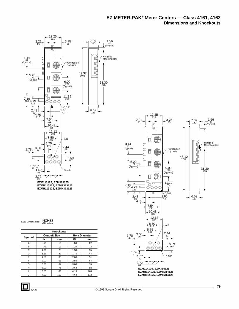
795/99 © 1999 Square D All Rights Reserved
12.25311
2.2156
3.7595
7.09180
1.5640
(Typical)
3.4487
(Typical)
2.4863
1.6542
4.59117
7.54192
10.48266
5.20132
(Typical)
4.79122
7.10180
42.371076
9.00229
(Typical)
11.19284
31.30795
C,D,E
C,D,E
A,B
HangingMounting Rail
Omitted on1f Units
EZM113125, EZM313125EZMR113125, EZMR313125EZMH113125, EZMH313125
6.59167
6.59167
2.44623.00
76
5.75146
8.50216
2.7269
12.12308
1.6742
1.6241
1.7845
12.25311
2.2156
7.09180
1.5640
(Typical)
3.4487
(Typical)
2.4863
1.6542
4.59117
7.54192
10.48266
5.20132
(Typical)
4.79122
7.10180
48.121222
9.00229
(Typical)
11.19284
31.30795
C,D,E
HangingMounting Rail
Omitted on1f Units
EZM114125, EZM314125EZMR114125, EZMR314125EZMH114125, EZMH314125
6.59167
6.59167
2.44623.00
76
5.75146
8.50216
2.7269
12.12308
1.6742
1.6241
1.7845
C,D,E
A,B
3.7595
Knockouts
SymbolConduit Size Hole DiameterIN mm IN mm
A .50 13 .88 22
B .75 19 1.25 32
C 1.00 25 1.38 35
D 1.25 32 1.75 44
E 1.50 38 2.00 51
F 2.00 51 2.50 64
G 2.50 64 3.00 76
H 3.00 76 3.63 92
I 3.50 89 4.13 105
J 4.00 102 4.63 118
EZ METER-PAK ® Meter Centers — Class 4161, 4162Dimensions and Knockouts
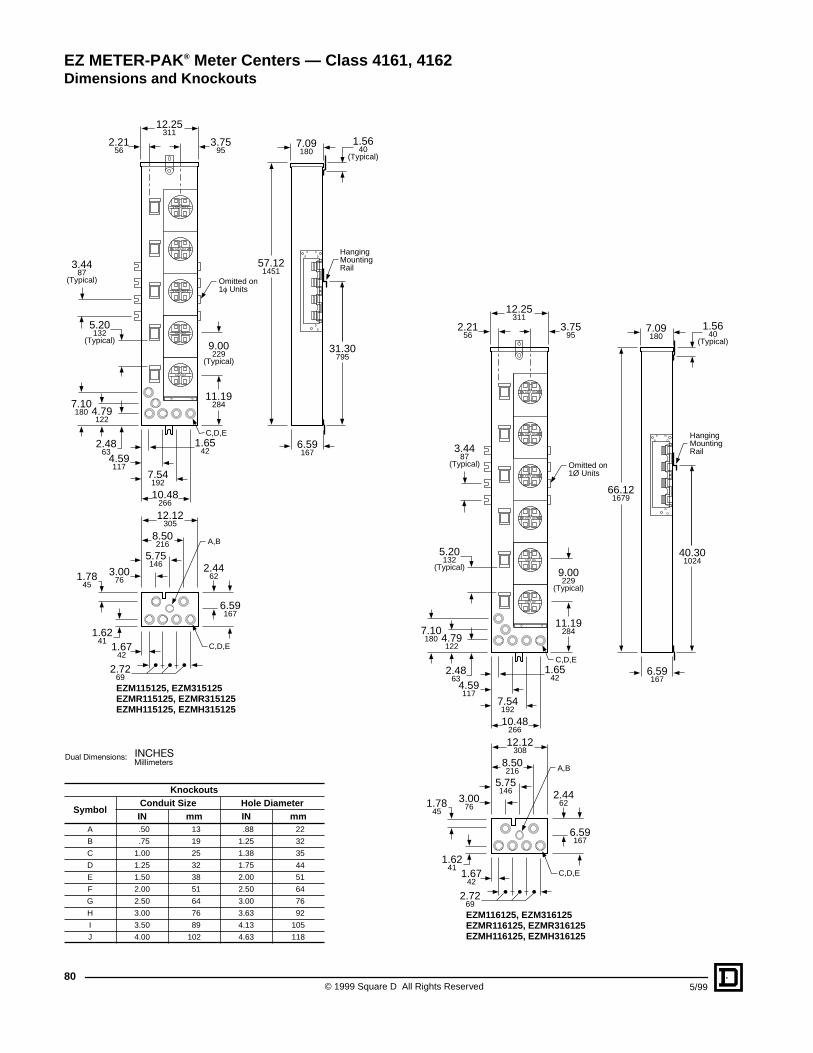
© 1999 Square D All Rights Reserved80
5/99
12.25311
2.2156
7.09180
1.5640
(Typical)
3.4487
(Typical)
2.4863
1.6542
4.59117
7.54192
10.48266
5.20132
(Typical)
4.79122
7.10180
57.121451
9.00229
(Typical)
11.19284
31.30795
6.59167
6.59167
2.44623.00
76
5.75146
8.50216
2.7269
12.12305
1.6742
1.6241
1.7845
C,D,E
HangingMountingRail
Omitted on1f Units
EZM115125, EZM315125EZMR115125, EZMR315125EZMH115125, EZMH315125
C,D,E
A,B
3.7595
12.25311
2.2156
7.09180
1.5640
(Typical)
3.4487
(Typical)
2.4863
1.6542
4.59117
7.54192
10.48266
5.20132
(Typical)
4.79122
7.10180
66.121679
9.00229
(Typical)
11.19284
40.301024
6.59167
6.59167
2.44623.00
76
5.75146
8.50216
2.7269
12.12308
1.6742
1.6241
1.7845
C,D,E
HangingMountingRail
Omitted on1Ø Units
EZM116125, EZM316125EZMR116125, EZMR316125EZMH116125, EZMH316125
C,D,E
A,B
3.7595
Knockouts
SymbolConduit Size Hole DiameterIN mm IN mm
A .50 13 .88 22
B .75 19 1.25 32
C 1.00 25 1.38 35
D 1.25 32 1.75 44
E 1.50 38 2.00 51
F 2.00 51 2.50 64
G 2.50 64 3.00 76
H 3.00 76 3.63 92
I 3.50 89 4.13 105
J 4.00 102 4.63 118
EZ METER-PAK ® Meter Centers — Class 4161, 4162Dimensions and Knockouts
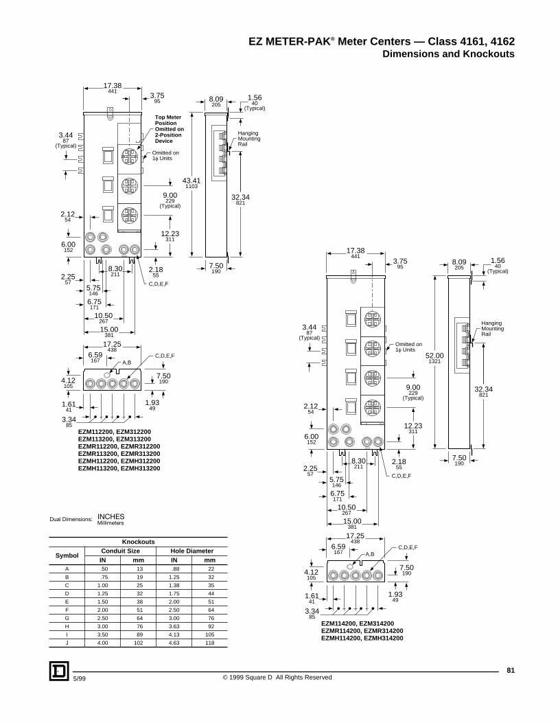
815/99 © 1999 Square D All Rights Reserved
17.38441
8.09205
7.50190
1.5640
(Typical)
3.4487
(Typical)
2.2557
2.1855
6.75171
8.30211
5.75146
6.00152
2.1254
10.50267
15.00381
43.411103
9.00229
(Typical)
12.23311
32.34821
7.50190
1.9349
6.59167
17.25438
3.3485
1.6141
4.12105
HangingMountingRail
Omitted on1f Units
Top MeterPositionOmitted on2-PositionDevice
EZM112200, EZM312200EZM113200, EZM313200EZMR112200, EZMR312200EZMR113200, EZMR313200EZMH112200, EZMH312200EZMH113200, EZMH313200
A,BC,D,E,F
C,D,E,F
3.7595
17.38441
8.09205
7.50190
1.5640
(Typical)
3.4487
(Typical)
2.2557
2.1855
6.75171
5.75146
6.00152
2.1254
10.50267
15.00381
52.001321
9.00229
(Typical)
12.23311
32.34821
HangingMountingRail
Omitted on1f Units
EZM114200, EZM314200EZMR114200, EZMR314200EZMH114200, EZMH314200
8.30211
7.50190
1.9349
6.59167
17.25438
3.3485
1.6141
4.12105
A,BC,D,E,F
C,D,E,F
3.7595
Knockouts
SymbolConduit Size Hole DiameterIN mm IN mm
A .50 13 .88 22
B .75 19 1.25 32
C 1.00 25 1.38 35
D 1.25 32 1.75 44
E 1.50 38 2.00 51
F 2.00 51 2.50 64
G 2.50 64 3.00 76
H 3.00 76 3.63 92
I 3.50 89 4.13 105
J 4.00 102 4.63 118
EZ METER-PAK ® Meter Centers — Class 4161, 4162Dimensions and Knockouts
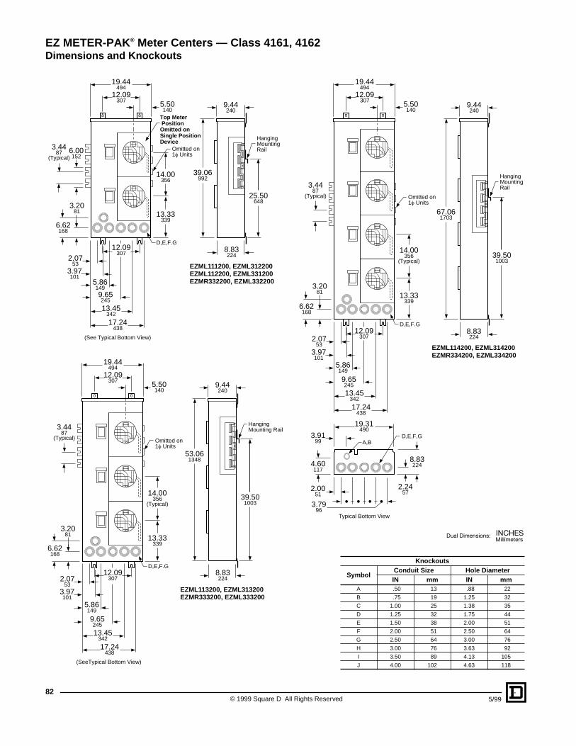
© 1999 Square D All Rights Reserved82
5/99
19.44494
9.44240
12.09307
12.09307
3.4487
(Typical)
3.2081
2.0753
3.97101
5.861499.65245
13.45342
17.24438
6.00152
6.62168
39.06992
13.33339
14.00356
25.50648
8.83224
D,E,F.G
HangingMountingRailOmitted on
1f Units
Top Meter PositionOmitted onSingle PositionDevice
EZML111200, EZML312200EZML112200, EZML331200EZMR332200, EZML332200
5.50140
(See Typical Bottom View)
9.44240
12.09307
3.4487
(Typical)
3.2081
2.0753
3.97101
5.86149
9.65245
13.45342
17.24438
6.62168
53.061348
13.33339
14.00356
(Typical)39.501003
D,E,F.G
HangingMounting Rail
Omitted on1f Units
EZML113200, EZML313200EZMR333200, EZML333200
8.83224
19.44494
12.09307
5.50140
(SeeTypical Bottom View)
Knockouts
SymbolConduit Size Hole DiameterIN mm IN mm
A .50 13 .88 22
B .75 19 1.25 32
C 1.00 25 1.38 35
D 1.25 32 1.75 44
E 1.50 38 2.00 51
F 2.00 51 2.50 64
G 2.50 64 3.00 76
H 3.00 76 3.63 92
I 3.50 89 4.13 105
J 4.00 102 4.63 118
9.44240
12.09307
3.4487
(Typical)
3.2081
2.0753
3.97101
5.86149
9.65245
13.45342
17.24438
6.62168
67.061703
13.33339
14.00356
(Typical)39.501003
8.83224
8.83224
2.2457
3.9199
D,E,F,G
3.7996
19.31490
2.0051
4.60117
D,E,F.G
HangingMountingRail
Omitted on1f Units
EZML114200, EZML314200EZMR334200, EZML334200
A,B
19.44494
12.09307
5.50140
Typical Bottom View
EZ METER-PAK ® Meter Centers — Class 4161, 4162Dimensions and Knockouts
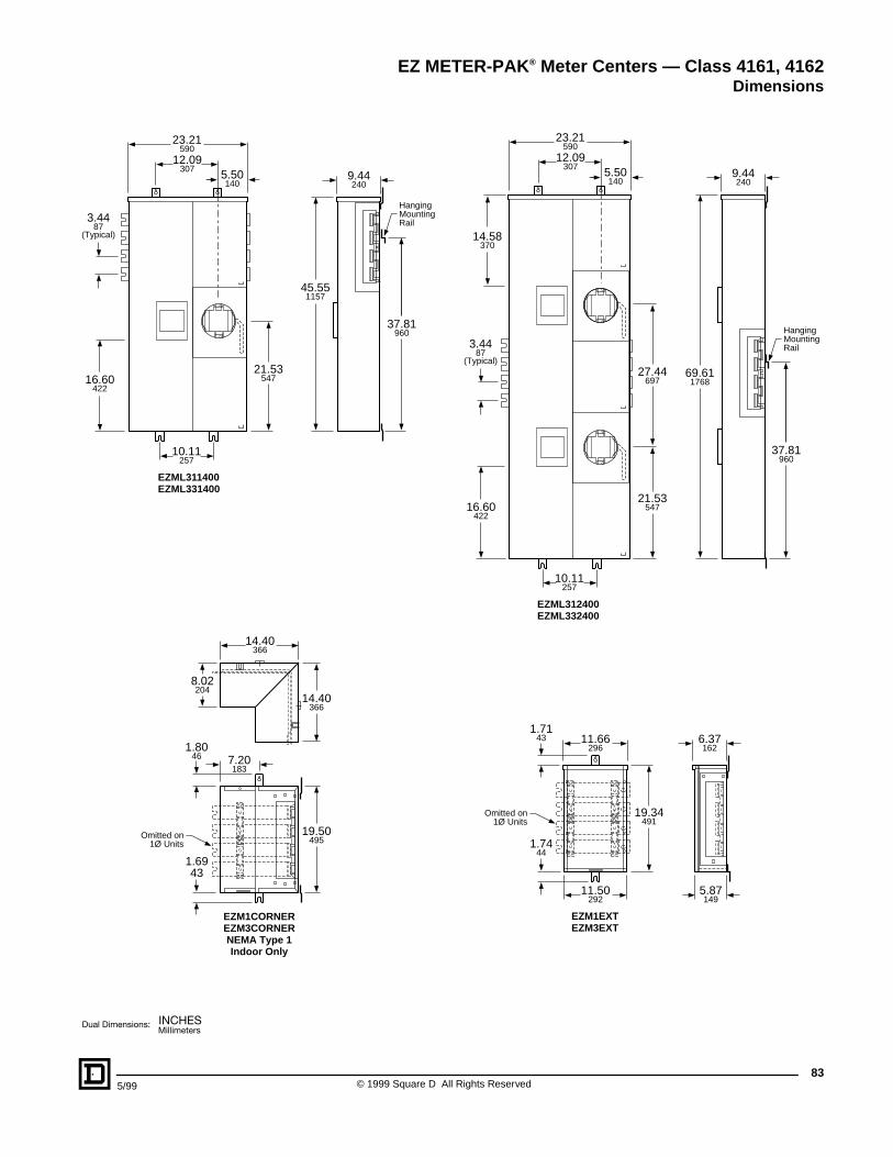
835/99 © 1999 Square D All Rights Reserved
9.44240
10.11257
3.4487
(Typical)
45.551157
21.53547
37.81960
HangingMountingRail
EZML311400EZML331400
16.60422
23.21590
12.09307
5.50140
9.44240
3.4487
(Typical)
14.58370
16.60422
69.611768
21.53547
37.81960
HangingMountingRail
27.44697
EZML312400EZML332400
10.11257
23.21590
12.09307
5.50140
11.66296
6.37162
1.7143
1.7444
11.50292
5.87149
19.34491
EZM1EXTEZM3EXT
Omitted on1Ø Units
8.02204
14.40366
7.20183
1.8046
1.6943
14.40366
19.50495
EZM1CORNEREZM3CORNERNEMA Type 1Indoor Only
Omitted on1Ø Units
EZ METER-PAK ® Meter Centers — Class 4161, 4162Dimensions
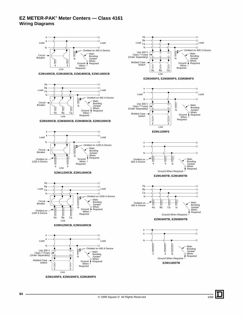
© 1999 Square D All Rights Reserved84
5/99
Load Load
Line
f
f
f f
N
EZM1400CB, EZM1600CB, EZM1800CB, EZM11000CB
CircuitBreaker
GroundWhen
Required
MainBondingJumperWhenRequired
N
Omitted on 400 A Device
Line
EZM3400CB, EZM3600CB, EZM3800CB, EZM31000CB
CircuitBreaker
Load Load
Af Bf Cf
Bf
Af
Cf
N
GroundWhen
Required
MainBondingJumperWhenRequired
N
Omitted on 400 A Device
Load Load
Line
f
f
f f
N
EZM11200CB, EZM11600CB
CircuitBreaker
GroundWhen
Required
MainBondingJumperWhenRequired
N
Omitted on 1200 A Device
Omitted on1200 A Device
Omitted on1200 A Device
Line
EZM31200CB, EZM31600CB
CircuitBreaker
Load Load
Af Bf Cf
Bf
Af
Cf
N
GroundWhen
Required
MainBondingJumperWhenRequired
N
Omitted on 1200 A Device
Load Load
Line
f
f
f
N
EZM1400FS, EZM1600FS, EZM1800FS
Use 300 VClass T Fuses
(Order Separately)
Molded CaseSwitch
f
GroundWhen
Required
MainBondingJumperWhenRequired
N
Omitted on 400 A Device
Line
EZM3400FS, EZM3600FS, EZM3800FS
Load Load
Af Bf Cf
Bf
Af
Cf
N
Use 300 VClass T Fuses
(Order Separately)
Molded CaseSwitch
GroundWhen
Required
MainBondingJumperWhenRequired
N
Omitted on 400 A Device
Load Load
Line
f
f
f
N
EZM11200FS
Use 300 VClass T Fuses
(Order Separately)
Molded CaseSwitch
f
GroundWhen
Required
MainBondingJumperWhenRequired
N
f
f
f f
N
EZM1400TB, EZM1800TB
Ground When Required
MainBondingJumperWhenRequired
N
Omitted on400 A Device
EZM3400TB, EZM3800TB
Af Bf Cf
Bf
Af
Cf
N
Ground When Required
MainBondingJumperWhenRequired
N
Omitted on400 A Device
f
f
f f
N
EZM11600TB
Ground When Required
MainBondingJumperWhenRequired
N
EZ METER-PAK ® Meter Centers — Class 4161Wiring Diagrams
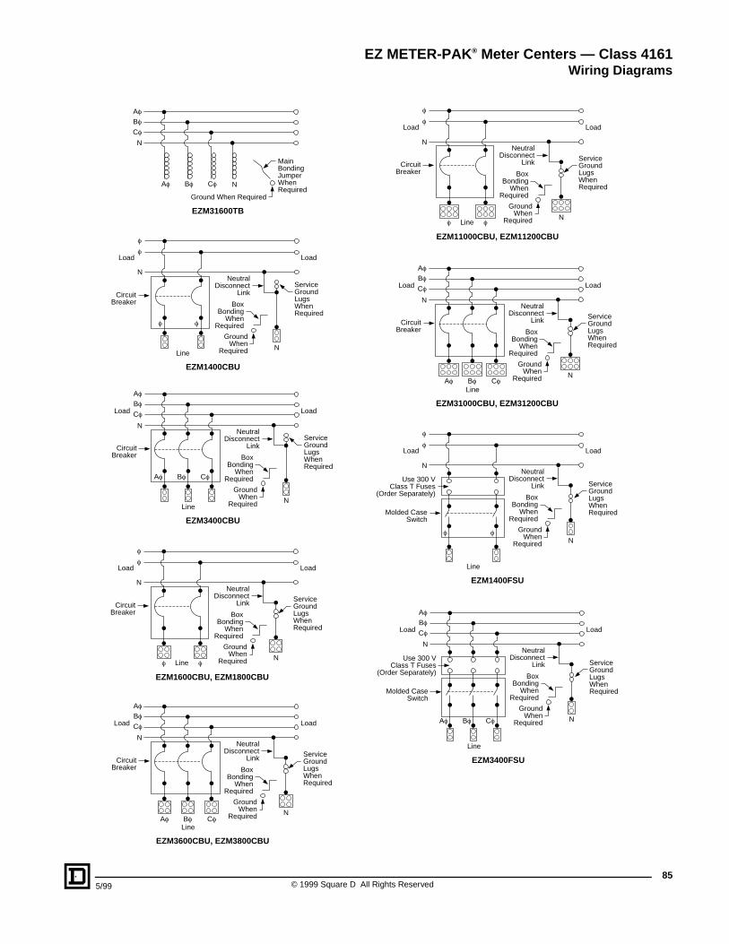
855/99 © 1999 Square D All Rights Reserved
EZM31600TB
Af Bf Cf
Bf
Af
Cf
N
Ground When Required
MainBondingJumperWhenRequired
N
Load Load
Line
f
f
f f
N
N
EZM1400CBU
CircuitBreaker
NeutralDisconnect
Link
BoxBonding
WhenRequired
GroundWhen
Required
ServiceGroundLugsWhenRequired
CircuitBreaker
N
NeutralDisconnect
Link
BoxBonding
WhenRequired
GroundWhen
Required
ServiceGroundLugsWhenRequired
Load Load
Line
Af Bf Cf
Bf
Af
Cf
N
EZM3400CBU
Load Load
Line
f
f
f f
N
N
EZM1600CBU, EZM1800CBU
CircuitBreaker
NeutralDisconnect
Link
BoxBonding
WhenRequired
GroundWhen
Required
ServiceGroundLugsWhenRequired
CircuitBreaker
Load Load
LineAf Bf Cf
Bf
Af
Cf
N
EZM3600CBU, EZM3800CBU
N
NeutralDisconnect
Link
BoxBonding
WhenRequired
GroundWhen
Required
ServiceGroundLugsWhenRequired
Load Load
Line
f
f
f f
N
N
EZM11000CBU, EZM11200CBU
CircuitBreaker
NeutralDisconnect
Link
BoxBonding
WhenRequired
GroundWhen
Required
ServiceGroundLugsWhenRequired
CircuitBreaker
Load Load
LineAf Bf Cf
Bf
Af
Cf
N
EZM31000CBU, EZM31200CBU
N
NeutralDisconnect
Link
BoxBonding
WhenRequired
GroundWhen
Required
ServiceGroundLugsWhenRequired
Load Load
Line
f
f
f f
N
N
EZM1400FSU
Use 300 VClass T Fuses
(Order Separately)
Molded CaseSwitch
NeutralDisconnect
Link
BoxBonding
WhenRequired
GroundWhen
Required
ServiceGroundLugsWhenRequired
Load Load
Line
Af Bf Cf
Bf
Af
Cf
N
N
EZM3400FSU
Use 300 VClass T Fuses
(Order Separately)
Molded CaseSwitch
NeutralDisconnect
Link
BoxBonding
WhenRequired
GroundWhen
Required
ServiceGroundLugsWhenRequired
EZ METER-PAK ® Meter Centers — Class 4161Wiring Diagrams
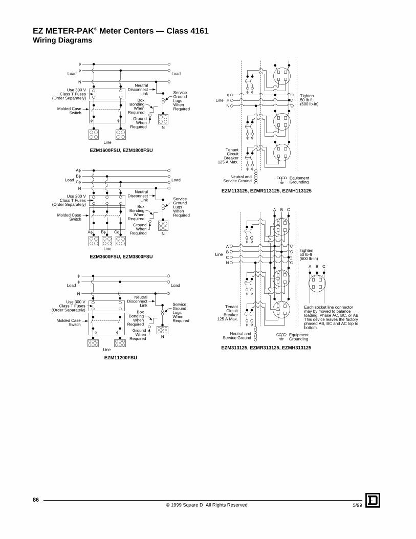
© 1999 Square D All Rights Reserved86
5/99
Load Load
Line
f
f
f f
N
N
EZM1600FSU, EZM1800FSU
Use 300 VClass T Fuses
(Order Separately)
Molded CaseSwitch
NeutralDisconnect
Link
BoxBonding
WhenRequired
GroundWhen
Required
ServiceGroundLugsWhenRequired
Load Load
Line
Af Bf Cf
Bf
Af
Cf
N
N
EZM3600FSU, EZM3800FSU
Use 300 VClass T Fuses
(Order Separately)
Molded CaseSwitch
NeutralDisconnect
Link
BoxBonding
WhenRequired
GroundWhen
Required
ServiceGroundLugsWhenRequired
Load Load
Line
f
f
f f
N
N
EZM11200FSU
Use 300 VClass T Fuses
(Order Separately)
Molded CaseSwitch
NeutralDisconnect
Link
BoxBonding
WhenRequired
GroundWhen
Required
ServiceGroundLugsWhenRequired
EZM113125, EZMR113125, EZMH113125
f
f f
f f
f f
N
TenantCircuit
Breaker125 A Max.
Line
Neutral andService Ground
EquipmentGrounding
Tighten50 lb-ft(600 lb-in)
f
EZM313125, EZMR313125, EZMH313125
f f
NCBA
f f
f f
TenantCircuit
Breaker125 A Max.
Line
Neutral andService Ground
EquipmentGrounding
Tighten50 lb-ft(600 lb-in)
A B C
A B C
Each socket line connectormay by moved to balanceloading. Phase AC, BC, or AB.This device leaves the factoryphased AB, BC and AC top tobottom.
EZ METER-PAK ® Meter Centers — Class 4161Wiring Diagrams
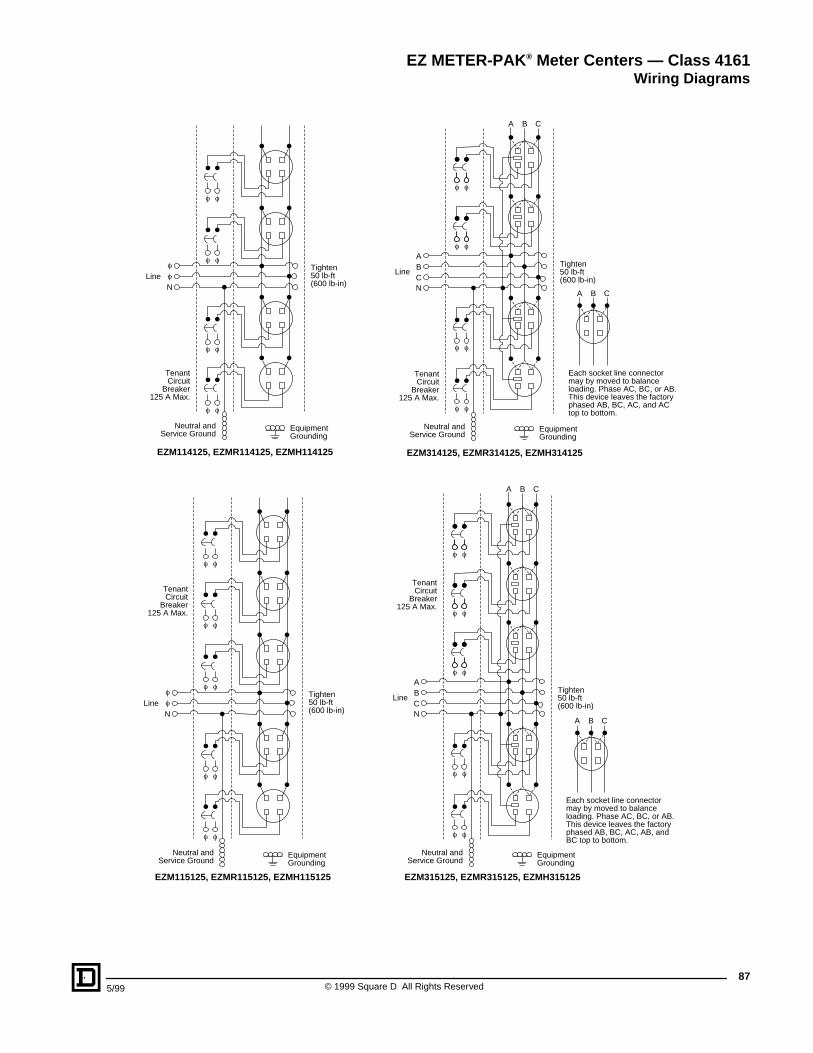
875/99 © 1999 Square D All Rights Reserved
EZM114125, EZMR114125, EZMH114125
f f
f f
f f
f f
ff
N
TenantCircuit
Breaker125 A Max.
Line
Neutral andService Ground
EquipmentGrounding
Tighten50 lb-ft(600 lb-in)
EZM314125, EZMR314125, EZMH314125
f f
NCBA
f f
f f
TenantCircuit
Breaker125 A Max.
Line
Neutral andService Ground
EquipmentGrounding
Tighten50 lb-ft(600 lb-in)
A B C
f f
A B C
Each socket line connectormay by moved to balanceloading. Phase AC, BC, or AB.This device leaves the factoryphased AB, BC, AC, and ACtop to bottom.
EZM115125, EZMR115125, EZMH115125
ff
N
TenantCircuit
Breaker125 A Max.
Line
Neutral andService Ground
EquipmentGrounding
Tighten50 lb-ft(600 lb-in)
f f
f f
f f
f f
f f
EZM315125, EZMR315125, EZMH315125
f f
NCBA
f f
f f
TenantCircuit
Breaker125 A Max.
Line
Neutral andService Ground
EquipmentGrounding
Tighten50 lb-ft(600 lb-in)
A B C
f f
f f
A B C
Each socket line connectormay by moved to balanceloading. Phase AC, BC, or AB.This device leaves the factoryphased AB, BC, AC, AB, andBC top to bottom.
EZ METER-PAK ® Meter Centers — Class 4161Wiring Diagrams
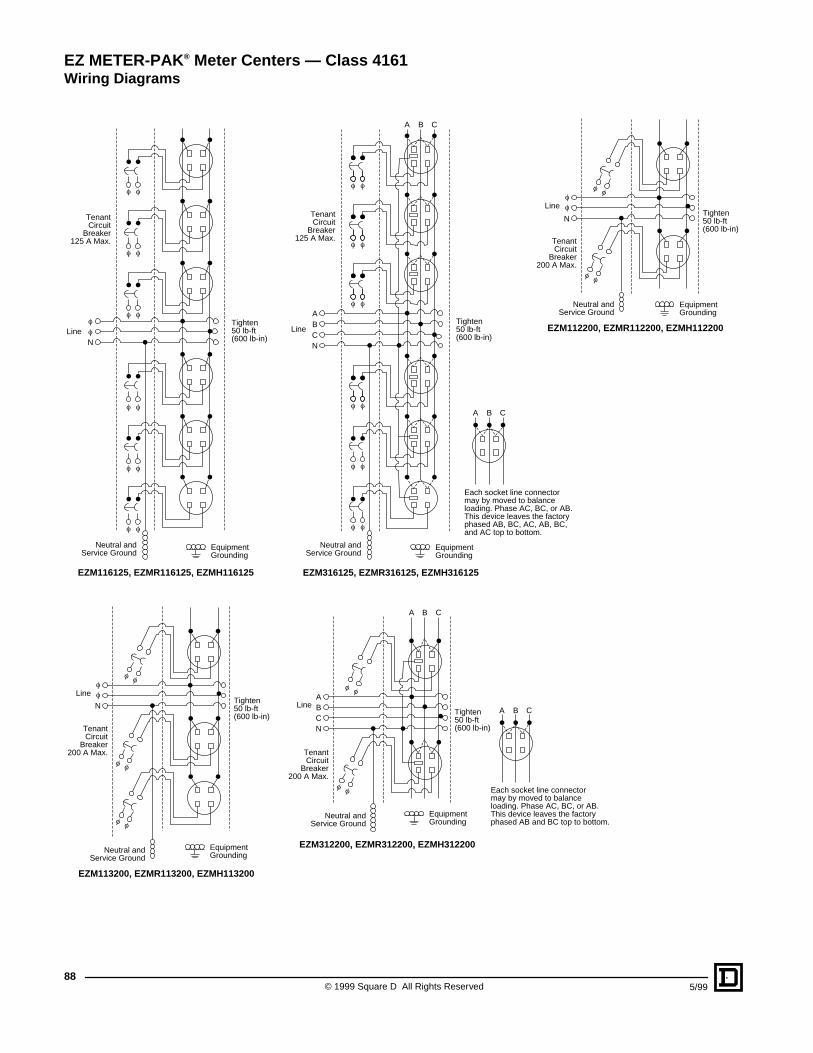
© 1999 Square D All Rights Reserved88
5/99
EZM116125, EZMR116125, EZMH116125
ffN
TenantCircuit
Breaker125 A Max.
Line
Neutral andService Ground
EquipmentGrounding
Tighten50 lb-ft(600 lb-in)
f f
f f
f f
f f
f f
f f
EZM316125, EZMR316125, EZMH316125
f f
NCBA
f f
f f
TenantCircuit
Breaker125 A Max.
Line
Neutral andService Ground
EquipmentGrounding
Tighten50 lb-ft(600 lb-in)
A B C
f f
f f
f fA B C
Each socket line connectormay by moved to balanceloading. Phase AC, BC, or AB.This device leaves the factoryphased AB, BC, AC, AB, BC,and AC top to bottom.
EZM112200, EZMR112200, EZMH112200
N
f f
f f
TenantCircuit
Breaker200 A Max.
Line
Neutral andService Ground
EquipmentGrounding
Tighten50 lb-ft(600 lb-in)
ff
EZM113200, EZMR113200, EZMH113200
N
f f
f f
f f
TenantCircuit
Breaker200 A Max.
Line
Neutral andService Ground
EquipmentGrounding
Tighten50 lb-ft(600 lb-in)
ff
EZM312200, EZMR312200, EZMH312200
NCBA
A B C
f f
f f
TenantCircuit
Breaker200 A Max.
Line
Neutral andService Ground
EquipmentGrounding
Tighten50 lb-ft(600 lb-in)
A B C
Each socket line connectormay by moved to balanceloading. Phase AC, BC, or AB.This device leaves the factoryphased AB and BC top to bottom.
EZ METER-PAK ® Meter Centers — Class 4161Wiring Diagrams
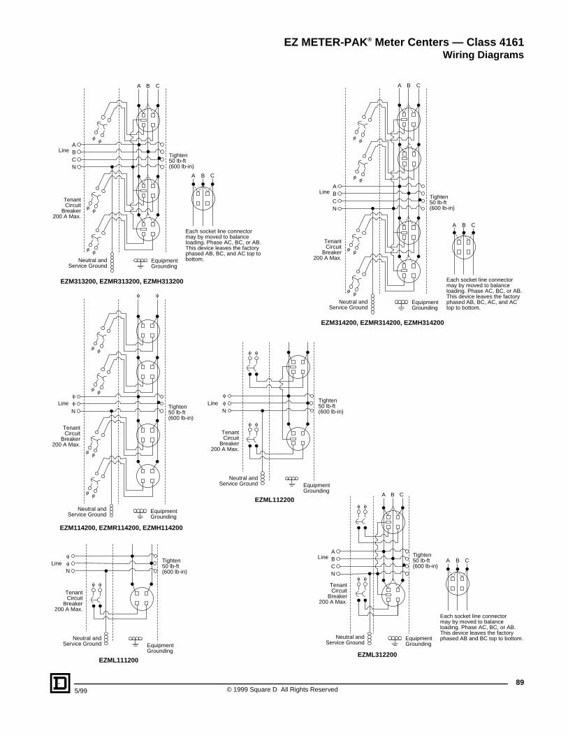
895/99 © 1999 Square D All Rights Reserved
EZM313200, EZMR313200, EZMH313200
NCBA
A B C
f f
f f
TenantCircuit
Breaker200 A Max.
Line
Neutral andService Ground
EquipmentGrounding
Tighten50 lb-ft(600 lb-in)
f f
A B C
Each socket line connectormay by moved to balanceloading. Phase AC, BC, or AB.This device leaves the factoryphased AB, BC, and AC top tobottom.
EZM114200, EZMR114200, EZMH114200
N
f f
f f
f f
f f
TenantCircuit
Breaker200 A Max.
Line
Neutral andService Ground
EquipmentGrounding
Tighten50 lb-ft(600 lb-in)
f f
ff
EZM314200, EZMR314200, EZMH314200
NCBA
A B C
f f
f f
TenantCircuit
Breaker200 A Max.
Line
Neutral andService Ground
EquipmentGrounding
Tighten50 lb-ft(600 lb-in)
f f
f f
A B C
Each socket line connectormay by moved to balanceloading. Phase AC, BC, or AB.This device leaves the factoryphased AB, BC, AC, and ACtop to bottom.
ff
f f
NLine Tighten
50 lb-ft(600 lb-in)
EZML111200
TenantCircuit
Breaker200 A Max.
Neutral andService Ground Equipment
Grounding
f
f f
f f
fN
Line Tighten50 lb-ft(600 lb-in)
EZML112200
TenantCircuit
Breaker200 A Max.
Neutral andService Ground Equipment
Grounding
f f
f f
EZML312200
NCBA
A B C
TenantCircuit
Breaker200 A Max.
Line
Neutral andService Ground
EquipmentGrounding
Tighten50 lb-ft(600 lb-in)
A B C
Each socket line connectormay by moved to balanceloading. Phase AC, BC, or AB.This device leaves the factoryphased AB and BC top to bottom.
EZ METER-PAK ® Meter Centers — Class 4161Wiring Diagrams
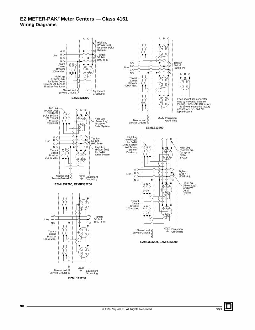
© 1999 Square D All Rights Reserved90
5/99
NCBA
A C B
A B C
Line Tighten50 lb-ft(600 lb-in)
EZML331200
TenantCircuit
Breaker200 A Max.
High Leg(Power Leg)
for 3f4W DeltaSystem (All TenantBreaker Positions)
High Leg(Power Leg)for 3f4W DeltaSystem
Neutral andService Ground
EquipmentGrounding
NCBA
A C B
A B C
LineTighten50 lb-ft(600 lb-in)
A B C
EZML332200, EZMR332200
TenantCircuit
Breaker200 A Max.
Neutral andService Ground
EquipmentGrounding
High Leg(Power Leg)
for 3f4WDelta System
(All TenantBreaker
Positions)
High Leg(Power Leg)for 3f4WDelta System
High Leg(Power Leg)for 3f4WDelta System
f
f f
f f
f f
f
NLine
Tighten50 lb-ft(600 lb-in)
EZML113200
TenantCircuit
Breaker125 A Max.
Neutral andService Ground
EquipmentGrounding
Line
Tighten50 lb-ft(600 lb-in)
EZML313200
TenantCircuit
Breaker400 A Max.
Neutral andService Ground
EquipmentGrounding
NCBA
A B C
f f
f f
f f
A B C
Each socket line connectormay by moved to balanceloading. Phase AC, BC, or AB.This device leaves the factoryphased AB, BC, and ACtop to bottom.
NCBA
A C B
A B C
LineTighten50 lb-ft(600 lb-in)
A B C
A B C
EZML333200, EZMR333200
TenantCircuit
Breaker200 A Max.
Neutral andService Ground
EquipmentGrounding
High Leg(Power Leg)
for 3f4WDelta System
(All TenantBreaker
Positions)
High Leg(Power Leg)for 3f4WDeltaSystem
High Leg(Power Leg)for 3f4WDeltaSystem
EZ METER-PAK ® Meter Centers — Class 4161Wiring Diagrams
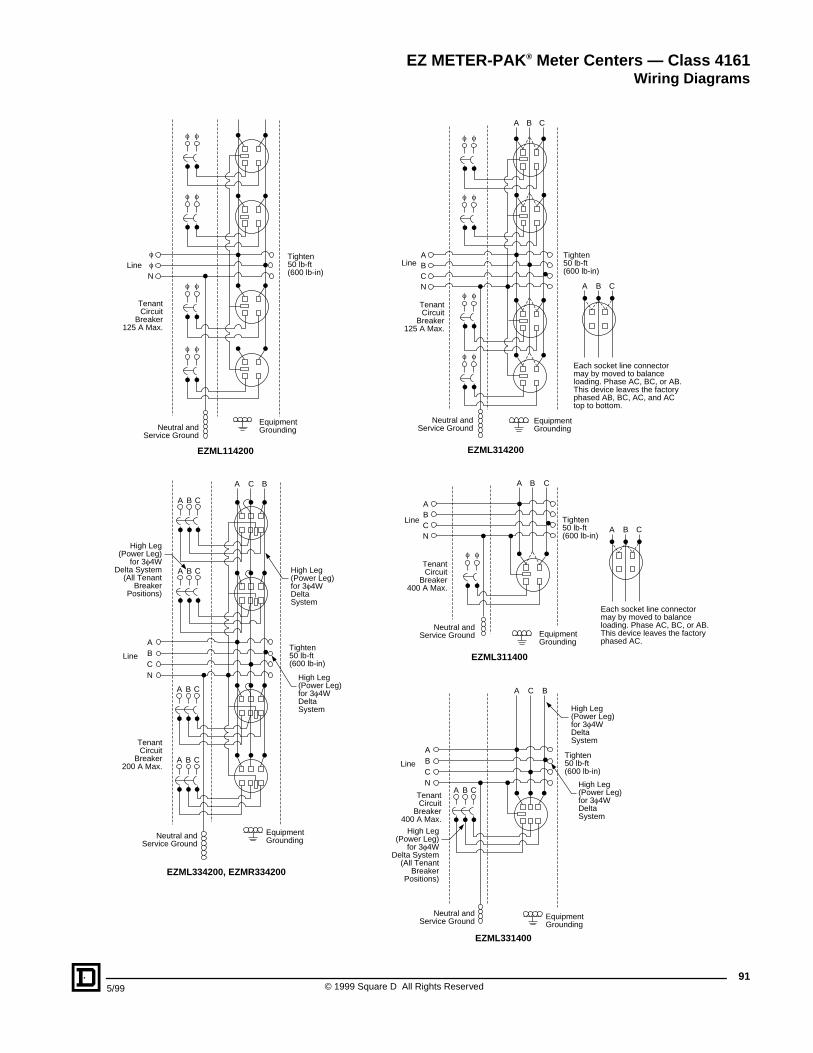
915/99 © 1999 Square D All Rights Reserved
f
f f
f f
f f
f f
f
NLine
Tighten50 lb-ft(600 lb-in)
EZML114200
TenantCircuit
Breaker125 A Max.
Neutral andService Ground
EquipmentGrounding
EZML314200
NCBA
A B C
TenantCircuit
Breaker125 A Max.
Line
Neutral andService Ground
EquipmentGrounding
Tighten50 lb-ft(600 lb-in)
f f
f f
f f
f f
A B C
Each socket line connectormay by moved to balanceloading. Phase AC, BC, or AB.This device leaves the factoryphased AB, BC, AC, and ACtop to bottom.
NCBA
A C B
A B C
LineTighten50 lb-ft(600 lb-in)
A B C
A B C
EZML334200, EZMR334200
TenantCircuit
Breaker200 A Max.
Neutral andService Ground
EquipmentGrounding
High Leg(Power Leg)
for 3f4WDelta System
(All TenantBreaker
Positions)
High Leg(Power Leg)for 3f4WDeltaSystem
High Leg(Power Leg)for 3f4WDeltaSystem
A B C
EZML311400
f fTenantCircuit
Breaker400 A Max.
Line
NCBA
Neutral andService Ground Equipment
Grounding
Tighten50 lb-ft(600 lb-in)
A B C
Each socket line connectormay by moved to balanceloading. Phase AC, BC, or AB.This device leaves the factoryphased AC.
A B C
NCBA
A C B
A B C
LineTighten50 lb-ft(600 lb-in)
EZML331400
TenantCircuit
Breaker400 A Max.
Neutral andService Ground
EquipmentGrounding
High Leg(Power Leg)
for 3f4WDelta System
(All TenantBreaker
Positions)
High Leg(Power Leg)for 3f4WDeltaSystem
High Leg(Power Leg)for 3f4WDeltaSystem
EZ METER-PAK ® Meter Centers — Class 4161Wiring Diagrams
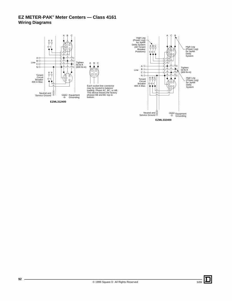
© 1999 Square D All Rights Reserved92
5/99
EZML312400
A B C
TenantCircuit
Breaker400 A Max.
Line
NCBA
Neutral andService Ground Equipment
Grounding
Tighten50 lb-ft(600 lb-in)
f f
f f
A B C
Each socket line connectormay by moved to balanceloading. Phase AC, BC, or AB.This device leaves the factoryphased AB and BC top tobottom.
NCBA
A C B
A B C
LineTighten50 lb-ft(600 lb-in)
A B C
EZML332400
TenantCircuit
Breaker400 A Max.
Neutral andService Ground
EquipmentGrounding
High Leg(Power Leg)
for 3f4WDelta System
(All TenantBreaker
Positions)
High Leg(Power Leg)for 3f4WDeltaSystem
High Leg(Power Leg)for 3f4WDeltaSystem
EZ METER-PAK ® Meter Centers — Class 4161Wiring Diagrams
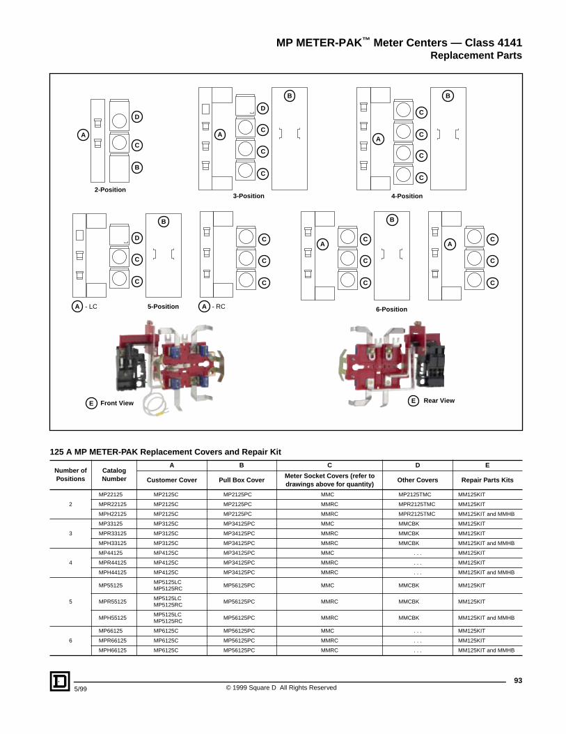
935/99 © 1999 Square D All Rights Reserved
125 A MP METER-PAK Replacement Covers and Repair Kit
Number of Positions
Catalog Number
A B C D E
Customer Cover Pull Box CoverMeter Socket Covers (refer to drawings above for quantity)
Other Covers Repair Parts Kits
2
MP22125 MP2125C MP2125PC MMC MP2125TMC MM125KIT
MPR22125 MP2125C MP2125PC MMRC MPR2125TMC MM125KIT
MPH22125 MP2125C MP2125PC MMRC MPR2125TMC MM125KIT and MMHB
3
MP33125 MP3125C MP34125PC MMC MMCBK MM125KIT
MPR33125 MP3125C MP34125PC MMRC MMCBK MM125KIT
MPH33125 MP3125C MP34125PC MMRC MMCBK MM125KIT and MMHB
4
MP44125 MP4125C MP34125PC MMC . . . MM125KIT
MPR44125 MP4125C MP34125PC MMRC . . . MM125KIT
MPH44125 MP4125C MP34125PC MMRC . . . MM125KIT and MMHB
5
MP55125MP5125LCMP5125RC
MP56125PC MMC MMCBK MM125KIT
MPR55125MP5125LCMP5125RC
MP56125PC MMRC MMCBK MM125KIT
MPH55125MP5125LCMP5125RC
MP56125PC MMRC MMCBK MM125KIT and MMHB
6
MP66125 MP6125C MP56125PC MMC . . . MM125KIT
MPR66125 MP6125C MP56125PC MMRC . . . MM125KIT
MPH66125 MP6125C MP56125PC MMRC . . . MM125KIT and MMHB
MP METER-PAK™ Meter Centers — Class 4141Replacement Parts
D
A
C
B
2-Position
D
A - LC A - RC
B
C
C
5-Position
A
B
C
D
C
C
E
C
C
C
A A
B
6-Position
C
C
C
C
C
C
3-Position
A
B
C
C
C
C
4-Position
Front View E Rear View
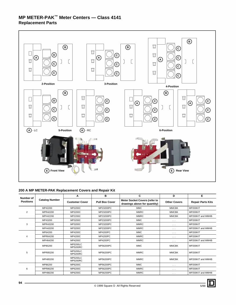
© 1999 Square D All Rights Reserved94
5/99
200 A MP METER-PAK Replacement Covers and Repair Kit
Number of Positions
Catalog NumberA B C D E
Customer Cover Pull Box CoverMeter Socket Covers (refer to drawings above for quantity)
Other Covers Repair Parts Kits
2
MP42200 MP2200C MP23200PC MMC MMCBK MP200KIT
MPR42200 MP2200C MP23200PC MMRC MMCBK MP200KIT
MPH42200 MP2200C MP23200PC MMRC MMCBK MP200KIT and MMHB
3
MP43200 MP3200C MP23200PC MMC . . . MP200KIT
MPR43200 MP3200C MP23200PC MMRC . . . MP200KIT
MPH43200 MP3200C MP23200PC MMRC . . . MP200KIT and MMHB
4
MP64200 MP4200C MP4200PC MMC . . . MP200KIT
MPR64200 MP4200C MP4200PC MMRC . . . MP200KIT
MPH64200 MP4200C MP4200PC MMRC . . . MP200KIT and MMHB
5
MP85200MP5200LCMP5200RC
MP56200PC MMC MMCBK MP200KIT
MPR85200MP5200LCMP5200RC
MP56200PC MMRC MMCBK MP200KIT
MPH85200MP5200LCMP5200RC
MP56200PC MMRC MMCBK MP200KIT and MMHB
6
MP86200 MP6200C MP56200PC MMC . . . MP200KIT
MPR86200 MP6200C MP56200PC MMRC . . . MP200KIT
MPH86200 MP6200C MP56200PC MMRC . . . MP200KIT and MMHB
MP METER-PAK™ Meter Centers — Class 4141Replacement Parts
DA
B
C
C
2-Position
D
A - LC A - RC
B
C
C
5-Position
A
B
C
C
C
C
C
C
A A
B
6-Position
C
C
C
C
C
C
3-Position
A
B
C
C
C
C
4-Position
Front View EE Rear View
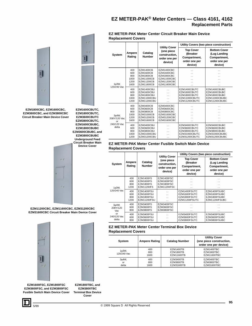
955/99 © 1999 Square D All Rights Reserved
EZ METER-PAK Meter Center Circuit Breaker Main Device Replacement Covers
EZ METER-PAK Meter Center Fusible Switch Main Device Replacement Covers
EZ METER-PAK Meter Center Terminal Box Device Replacement Covers
SystemAmpereRating
CatalogNumber
Utility Cover (one piece
construction, order one per
device)
Utility Covers (two piece construction)
Top Cover (Breaker
Compartment, order one per
device)
Bottom Cover(Lug Landing Compartment, order one per
device)
1f3W,120/240 Vac
400 EZM1400CB EZM1400CBC … …600 EZM1600CB EZM1600CBC … …800 EZM1800CB EZM1800CBC … …
1000 EZM11000CB EZM11000CBC … …1200 EZM11200CB EZM11200CBC … …1600 EZM11600CB EZM11600CBC … …
400 EZM1400CBU … EZM1400CBUTC EZM1400CBUBC600 EZM1600CBU … EZM1600CBUTC EZM1600CBUBC800 EZM1800CBU … EZM1800CBUTC EZM1800CBUBC
1000 EZM11000CBU … EZM11000CBUTC EZM11000CBUBC1200 EZM11200CBU … EZM11200CBUTC EZM11200CBUBC
3f4W,208Y/120 Vac
or240/120 Vac
delta
400 EZM3400CB EZM3400CBC … …600 EZM3600CB EZM3600CBC … …800 EZM3800CB EZM3800CBC … …
1000 EZM31000CB EZM31000CBC … …1200 EZM31200CB EZM31200CBC … …1600 EZM31600CB EZM31600CBC … …
400 EZM3400CBU … EZM3400CBUTC EZM3400CBUBC600 EZM3600CBU … EZM3600CBUTC EZM3600CBUBC800 EZM3800CBU … EZM3800CBUTC EZM3800CBUBC
1000 EZM31000CBU … EZM31000CBUTC EZM31000CBUBC1200 EZM31200CBU … EZM31200CBUTC EZM31200CBUBC
SystemAmpereRating
CatalogNumber
Utility Cover (one piece
construction, order one per
device)
Utility Covers (two piece construction)
Top Cover (Breaker
Compartment, order one per
device)
Bottom Cover (Lug Landing Compartment, order one per
device)
1f3W,120/240 Vac
400 EZM1400FS EZM1400FSC … …600 EZM1600FS EZM1600FSC … …800 EZM1800FS EZM1800FSC … …
1200 EZM11200FS EZM11200FSC … …
400 EZM1400FSU … EZM1400FSUTC EZM1400FSUBC600 EZM1600FSU … EZM1600FSUTC EZM1600FSUBC800 EZM1800FSU … EZM1800FSUTC EZM1800FSUBC
1200 EZM11200FSU … EZM11200FSUTC EZM11200FSUBC
3f4W,208Y/120
Vacor
240/120 Vacdelta
400 EZM3400FS EZM3400FSC … …600 EZM3600FS EZM3600FSC … …800 EZM3800FS EZM3800FSC … …
400 EZM3400FSU … EZM3400FSUTC EZM3400FSUBC600 EZM3600FSU … EZM3600FSUTC EZM3600FSUBC800 EZM3800FSU … EZM3800FSUTC EZM3800FSUBC
System Ampere Rating Catalog NumberUtility Cover
(one piece construction, order one per device)
1f3W,120/240 Vac
400 EZM1400TB EZM1400TBC800 EZM1800TB EZM1800TBC
1600 EZM11600TB EZM11600TBC
3f4W,or
delta
400 EZM3400TB EZM3400TBC800 EZM3800TB EZM3800TBC
1600 EZM31600TB EZM31600TBC
EZM1600FSC, EZM1800FSCEZM3600FSC, and EZM3800FSC
Fusible Switch Main Device Cover
EZM1800TBC, and EZM3800TBC
Terminal Box Device Cover
EZM11200CBC, EZM11600CBC, EZM31200CBCEZM31600CBC Circuit Breaker Main Device Cover
EZM1600CBUTC, EZM1800CBUTC, EZM3600CBUTCEZM3800CBUTC, EZM1600CBUBC, EZM1800CBUBC
EZM3600CBUBC, and EZM3800CBUBC
Underground Feed Circuit Breaker Main
Device Cover
EZM1800CBC, EZM1600CBC,EZM3600CBC, and EZM3800CBCCircuit Breaker Main Device Cover
EZ METER-PAK® Meter Centers — Class 4161, 4162Replacement Parts
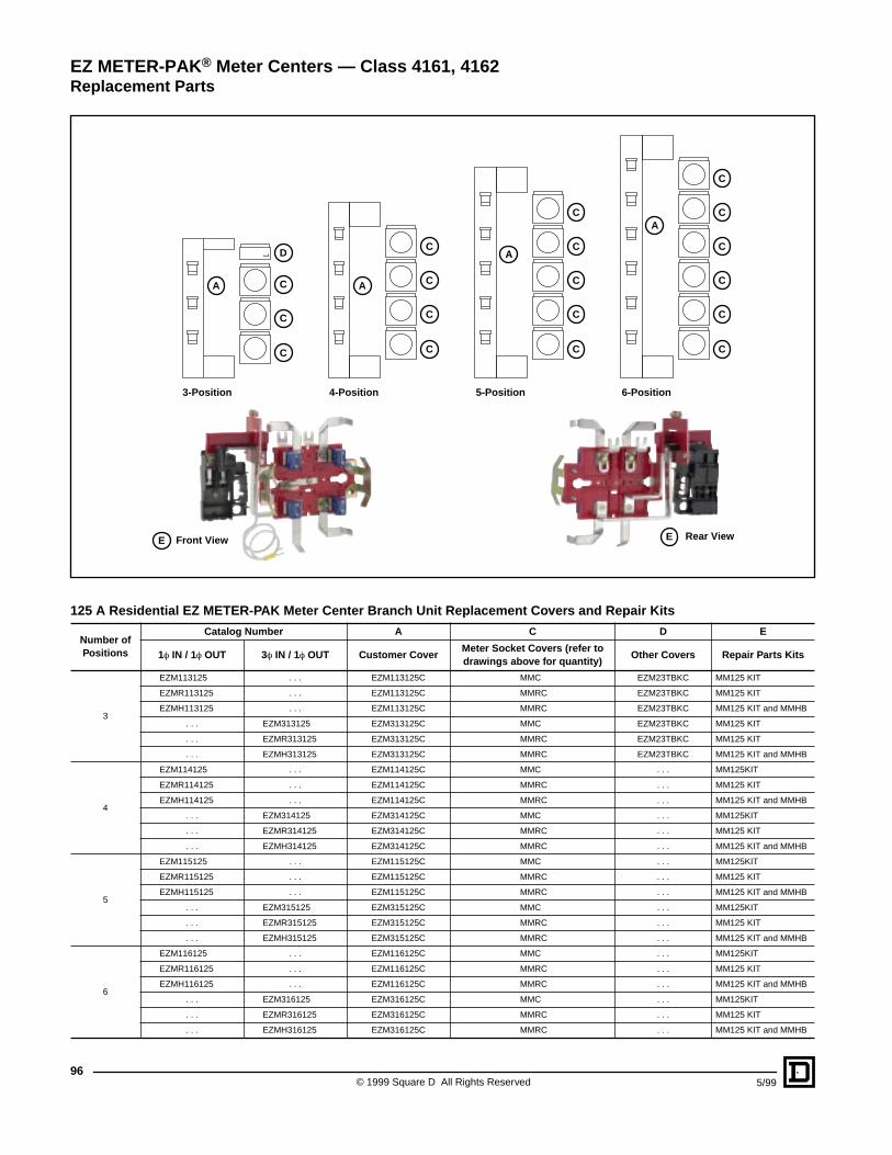
© 1999 Square D All Rights Reserved96
5/99
125 A Residential EZ METER-PAK Meter Center Branch Unit Replacement Covers and Repair Kits
Number of Positions
Catalog Number A C D E
1f IN / 1f OUT 3f IN / 1f OUT Customer CoverMeter Socket Covers (refer to drawings above for quantity)
Other Covers Repair Parts Kits
3
EZM113125 . . . EZM113125C MMC EZM23TBKC MM125 KIT
EZMR113125 . . . EZM113125C MMRC EZM23TBKC MM125 KIT
EZMH113125 . . . EZM113125C MMRC EZM23TBKC MM125 KIT and MMHB
. . . EZM313125 EZM313125C MMC EZM23TBKC MM125 KIT
. . . EZMR313125 EZM313125C MMRC EZM23TBKC MM125 KIT
. . . EZMH313125 EZM313125C MMRC EZM23TBKC MM125 KIT and MMHB
4
EZM114125 . . . EZM114125C MMC . . . MM125KIT
EZMR114125 . . . EZM114125C MMRC . . . MM125 KIT
EZMH114125 . . . EZM114125C MMRC . . . MM125 KIT and MMHB
. . . EZM314125 EZM314125C MMC . . . MM125KIT
. . . EZMR314125 EZM314125C MMRC . . . MM125 KIT
. . . EZMH314125 EZM314125C MMRC . . . MM125 KIT and MMHB
5
EZM115125 . . . EZM115125C MMC . . . MM125KIT
EZMR115125 . . . EZM115125C MMRC . . . MM125 KIT
EZMH115125 . . . EZM115125C MMRC . . . MM125 KIT and MMHB
. . . EZM315125 EZM315125C MMC . . . MM125KIT
. . . EZMR315125 EZM315125C MMRC . . . MM125 KIT
. . . EZMH315125 EZM315125C MMRC . . . MM125 KIT and MMHB
6
EZM116125 . . . EZM116125C MMC . . . MM125KIT
EZMR116125 . . . EZM116125C MMRC . . . MM125 KIT
EZMH116125 . . . EZM116125C MMRC . . . MM125 KIT and MMHB
. . . EZM316125 EZM316125C MMC . . . MM125KIT
. . . EZMR316125 EZM316125C MMRC . . . MM125 KIT
. . . EZMH316125 EZM316125C MMRC . . . MM125 KIT and MMHB
EZ METER-PAK® Meter Centers — Class 4161, 4162Replacement Parts
D
C
C
3-Position
CA
C
C
4-Position
CA
C
C
C
5-Position
C
AC
C
C
C
6-Position
C
A
C
C
C
E Front View E Rear View
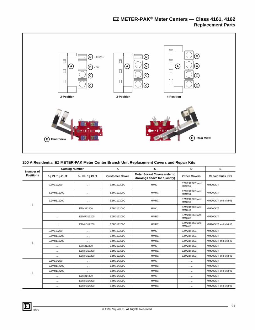
975/99 © 1999 Square D All Rights Reserved
200 A Residential EZ METER-PAK Meter Center Branch Unit Replacement Covers and Repair Kits
Number of Positions
Catalog Number A C D E
1f IN / 1f OUT 3f IN / 1f OUT Customer CoverMeter Socket Covers (refer to drawings above for quantity)
Other Covers Repair Parts Kits
2
EZM112200 . . . EZM112200C MMCEZM23TBKC andMMCBK
MM200KIT
EZMR112200 . . . EZM112200C MMRCEZM23TBKC andMMCBK
MM200KIT
EZMH112200 . . . EZM112200C MMRCEZM23TBKC andMMCBK
MM200KIT and MMHB
. . . EZM312200 EZM312200C MMCEZM23TBKC andMMCBK
MM200KIT
. . . EZMR312200 EZM312200C MMRCEZM23TBKC andMMCBK
MM200KIT
. . . EZMH312200 EZM312200C MMRCEZM23TBKC andMMCBK
MM200KIT and MMHB
3
EZM113200 . . . EZM113200C MMC EZM23TBKC MM200KIT
EZMR113200 . . . EZM113200C MMRC EZM23TBKC MM200KIT
EZMH113200 . . . EZM113200C MMRC EZM23TBKC MM200KIT and MMHB
. . . EZM313200 EZM313200C MMC EZM23TBKC MM200KIT
. . . EZMR313200 EZM313200C MMRC EZM23TBKC MM200KIT
. . . EZMH313200 EZM313200C MMRC EZM23TBKC MM200KIT and MMHB
4
EZM114200 . . . EZM114200C MMC . . . MM200KIT
EZMR114200 . . . EZM114200C MMRC . . . MM200KIT
EZMH114200 . . . EZM114200C MMRC . . . MM200KIT and MMHB
. . . EZM314200 EZM314200C MMC . . . MM200KIT
. . . EZMR314200 EZM314200C MMRC . . . MM200KIT
. . . EZMH314200 EZM314200C MMRC . . . MM200KIT and MMHB
EZ METER-PAK® Meter Centers — Class 4161, 4162Replacement Parts
D - TBKC
D - BK
C
C
2-Position
A
D
C
C
3-Position
CA
C
C
4-Position
CA
C
E Front View E Rear View
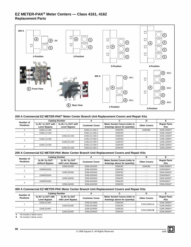
© 1999 Square D All Rights Reserved98
5/99
200 A Commercial EZ METER-PAK ® Meter Center Branch Unit Replacement Covers and Repair Kits
200 A Commercial EZ METER-PAK Meter Center Branch Unit Replacement Covers and Repair Kits
400 A Commercial EZ METER-PAK Meter Center Branch Unit Replacement Covers and Repair Kits
Number of Positions
Catalog Number A C D E
1f IN / 1f OUT with Lever Bypass
3f IN / 1f OUT with Lever Bypass
Customer CoverMeter Socket Covers (refer to drawings above for quantity)
Other CoversRepair Parts
Kits1 EZML111-200 . . . EZML111-200-C EZMCRC EZMCBK EZML1200KIT
2EZML112-200 . . . EZML112-200-C EZMCRC . . . EZML1200KIT
. . . EZML312-200 EZML312-200-C EZMCRC . . . EZML1200KIT
3EZML113-200 . . . EZML113-200-C EZMCRC . . . EZML1200KIT
. . . EZML313-200 EZML313-200-C EZMCRC . . . EZML1200KIT
4EZML114-200 … EZML114-200-C EZMCRC . . . EZML1200KIT
. . . EZML314-200 EZML314-200-C EZMCRC . . . EZML1200KIT
Number of Positions
Catalog Number A C D E
3f IN / 3f OUT without Bypass
3f IN / 3f OUTwith Lever Bypass
Customer CoverMeter Socket Covers (refer to drawings above for quantity)
Other CoversRepair Parts
Kits1 . . . EZML331200 EZML331200C EZMCRC EZMCBK EZML3200KIT
2EZMR332200 . . . EZML332200C EZMCRC . . . EZM3200KIT
. . . EZML332200 EZML332200C EZMCRC . . . EZML3200KIT
3EZMR333200 . . . EZML333200C EZMCRC . . . EZM3200KIT
. . . EZML333200 EZML333200C EZMCRC . . . EZML3200KIT
4EZMR334200 . . . EZML334200C EZMCRC . . . EZM3200KIT
. . . EZML334200 EZML334200C EZMCRC . . . EZML3200KIT
Number of Positions
Catalog Number A C D E
3f IN / 1f OUT with Lever Bypass
3f IN / 3f OUT with Lever Bypass
Customer CoverMeter Socket Covers (refer to drawings above for quantity)
Other CoversRepair Parts
Kits
1EZML311400 . . . EZML311400C EZMCRC
EZML400BK1qEZML1400KIT
. . . EZML331400 EZML331400C EZMCRC EZML3400KIT
2EZML312400 . . . EZML312400C EZMCRC
EZML400BK2cEZML1400KIT
. . . EZML332400 EZML332400C EZMCRC EZML3400KIT
q Kit includes 2 blank covers.c Kit includes 3 blank covers.
EZ METER-PAK® Meter Centers — Class 4161, 4162Replacement Parts
D - BK1
D - BK1
D - BK2
D - BK2
C
A
D - BK
C
A
C
A
D - BK2
C
C
A
C
C
AC
C
C
A
C
C
C
200 A
400 A
E Front View
1-Position
1-Position2-Position
2-Position
3-Position 4-Position
E Rear View
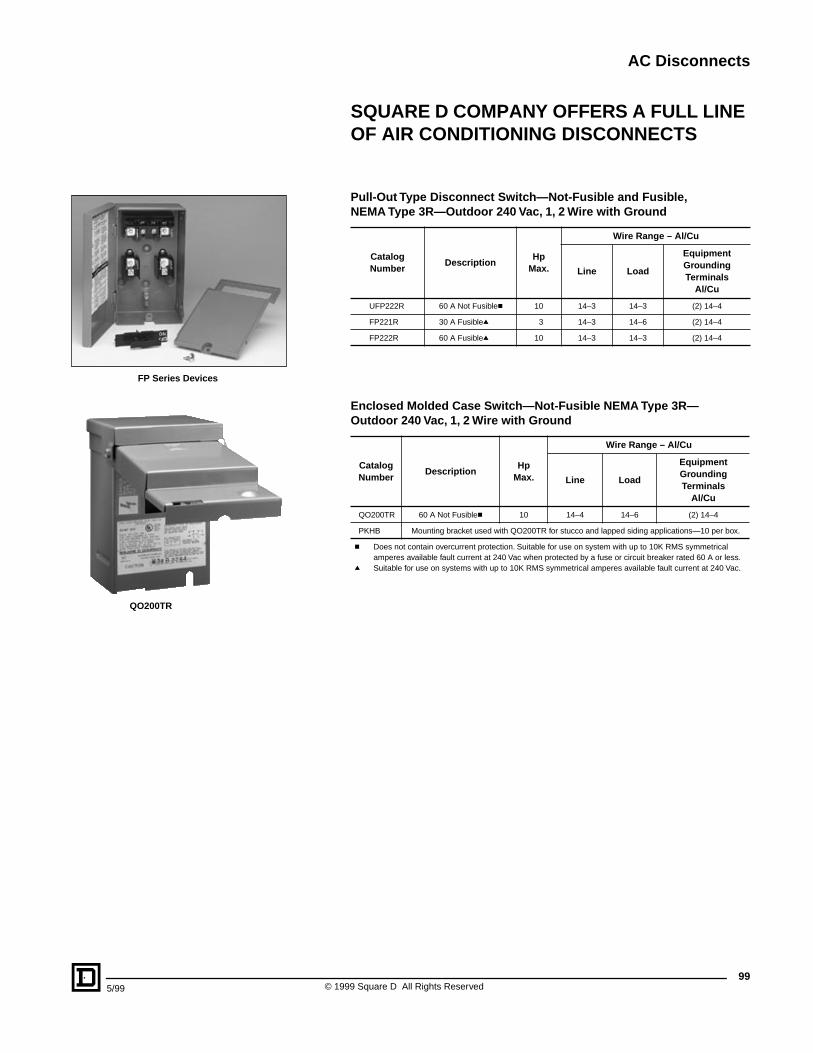
AC Disconnects
995/99 © 1999 Square D All Rights Reserved
SQUARE D COMPANY OFFERS A FULL LINE OF AIR CONDITIONING DISCONNECTS
Pull-Out Type Disconnect Switch—Not-Fusible and Fusible, NEMA Type 3R—Outdoor 240 Vac, 1, 2 Wire with Ground
Enclosed Molded Case Switch—Not-Fusible NEMA Type 3R— Outdoor 240 Vac, 1, 2 Wire with Ground
CatalogNumber
DescriptionHp
Max.
Wire Range – Al/Cu
Line Load
Equipment Grounding Terminals
Al/Cu
UFP222R 60 A Not Fusiblec 10 14–3 14–3 (2) 14–4
FP221R 30 A Fusibleq 3 14–3 14–6 (2) 14–4
FP222R 60 A Fusibleq 10 14–3 14–3 (2) 14–4
CatalogNumber
DescriptionHp
Max.
Wire Range – Al/Cu
Line Load
Equipment Grounding Terminals
Al/Cu
QO200TR 60 A Not Fusiblec 10 14–4 14–6 (2) 14–4
PKHB Mounting bracket used with QO200TR for stucco and lapped siding applications—10 per box.
c Does not contain overcurrent protection. Suitable for use on system with up to 10K RMS symmetrical amperes available fault current at 240 Vac when protected by a fuse or circuit breaker rated 60 A or less.
q Suitable for use on systems with up to 10K RMS symmetrical amperes available fault current at 240 Vac.
QO200TR
FP Series Devices

Catalog No. 4100CT9801 May 1999 © 1999 Square D All Rights Reserved.
QO, I-LINE, VISI-TITE, Square D and are Registered Trademarks of Square D Company or related companies.All other trademarks are the intellectual property of their respective companies.
Square D Company1601 Mercer RoadLexington, KY 40511(606) 243-8000www.squared.com


