

FIELD PROGRAMMABLE GATE ARRAY ARCHITECTURE OFPROPORTIONAL-INTEGRAL-DERIVATIVE CONTROLLER
ZULKIFLI YUSOF
UNIVERSITI TEKNOLOGI MALAYSIA

Replace this page with form PSZ 19:16 (Pind. 1/07), which can be obtained from SPS or your faculty.
Replace this page with the Cooperation Declaration form, which can be obtained from SPS or your faculty.

FIELD PROGRAMMABLE GATE ARRAY ARCHITECTURE OFPROPORTIONAL-INTEGRAL-DERIVATIVE CONTROLLER
ZULKIFLI YUSOF
A project report submitted in partial fulfilment of the
requirements for the award of the degree of Master of Engineering (Electrical - Computer and Microelectronic System)
Faculty of Electrical Engineering Universiti Teknologi Malaysia
JUNE 2015
"in The Name of Allah The Most Gracious The Most Merciful
seeking forgiveness from Rabb All-Hearer All-Sufficient”
iv
ACKNOWLEDGEMENT
Alhamdulillah, firstly I would like to express my highest and sincere gratefulness to the Almighty Allah S.W.T for his uncountable favor has helped me to completing this course.
Secondly, I would like to express my deepest gratitude to Dr. Muhammad Nadzir Marsono, my research supervisor, for his patient, guidance, enthusiastic
encouragement and useful critiques of this project.
Beside that, I would like to give my very highest appreciation to my employer, Intel for give oppotunity and funding my study.
Finally, I wish to extend my thanks to my beloved family and friends for their patient, support and encouragement towards completing this course work.

V
ABSTRACT
Proportional-integral-derivative (PID) control is widely used in control and automation. PID implementation in software especially using microcontroller requires a lot of CPU execution time. The performance of PID controller can be improved by
accelerating control function in hardware. Thus, the performance and throughput can be further improved when incorporated in FPGA architecture system. This project focuses on exploration of hardware architecture of PID controller and targeted for implementation on FPGA system. The architecture exploration include concurrent, serial and pipeline designs, functionality correctness and non-functional verification. These architectures was designed to support modularity and can be use for other
control applications. Serial design architecture of PID is able to reduce ~ 60% of datapath unit resources compared to concurrent design but it required five cycles to produce the output. High throughput can be achieve using pipeline design and required
7 more registers compared to concurrent design with pipeline speed up about 1.5 and five times compared to serial design architecture.

vi
ABSTRAK
Kawalan berkadar terus-berkamiran-pembeza (PID) digunakan secara meluas dalam sistem automasi. Perlaksanaan sistem kawalan berkadar terus-berkamiran- pembeza dalam bentuk perisian terutama pegawal terbenam memerlukan masa yang
panjang memproses arahan. Prestasi kawalan berkadar terus-berkamiran-pembeza dapat ditingkatkan dengan menjana fungsi kawalan ke dalam perkakasan. Oleh itu, prestasi dan hasil keluaran dapat ditingkatkan dengan lebih tinggi melalui penggabungan sistem seni bina FPGA. Projek ni memberi tumpuan kepada penerokaan seni bina perkakasan kawalan berkadar terus-berkamiran-pembeza yang boleh dilaksanakan melalui sistem FPGA. Penerokaan meliputi reka bentuk serentak, sesiri dan saluran paip, menguji ketepatan fungsinya dan aspek yang lain. Reka bentuk seni bina yang dibangunkan direka untuk menyokong kesesuaian modul dan boleh diguna pakai untuk kegunaan kawalan yang lain. Seni bina pengawal dengan reka bentuk sesiri dapat mengurangkan sumber pembinaan laluan data sebanyak 60 peratus berbanding rekabentuk serentak tetapi memerlukan masa lima kali ganda untuk mengeluarkan hasil keluaran. Pemprosessan tinggi boleh dihasilkan dengan menggunakan reka bentuk saluran paip dan ia memerlukan lebih tujuh penyimpan memori berbanding rekabentuk serentak dengan kelebihan 1.5 kali ganda hasil keluaran and lima kali ganda dibandingkan dengan reka bentuk sesiri.

TABLE OF CONTENTS
CHAPTER TITLE PAGE
DECLARATION iiDEDICATION iiiACKNOWLEDGEMENT ivABSTRACT vABSTRAK viTABLE OF CONTENTS viiLIST OF TABLES ixLIST OF FIGURES xLIST OF ABBREVIATIONS xi
1 INTRODUCTION 11.1 Overview 11.2 PID Controller 21.3 Problem Statement 3
1.4 Project Objective 31.5 Scope of Work 41.6 Report Overview 5
2 LITERATURE REVIEW 62.1 Introduction to PID controller 62.2 Closed-Loop Control System 72.3 PID Control 8
2.3.1 Proportional 82.3.2 Integral 92.3.3 Derivative 9
2.4 PID Design Techniques 102.5 FPGA for Digital Design 112.6 Related Work on PID in FPGA 122.7 Chapter Summary 13

viii
3 PID CONTROLLER ARCHITECTURE 143.1 Introduction 143.2 PID Incremental Algorithm 14
3.2.1 PID Architecture Development on FPGA 163.2.2 Concurrent Architecture Design 163.2.3 Serial Architecture Design 18
3.2.4 Pipeline Architecture Design 233.3 Chapter Summary 28
4 RESULTS ANDANALYSIS 294.1 Verification Methodology 294.2 Simulation Result 30
4.2.1 Concurrent Timing Simulation Result 304.2.2 Serial Timing Simulation Result 304.2.3 Pipeline Timing Simulation Result 31
4.3 Performance Analysis 324.4 Chapter Summary 33
5 CONCLUSION AND FUTURE WORK 345.1 Conclusion 345.2 Future Works 34
REFERENCES 35
LIST OF TABLES
TABLE NO. TITLE PAGE
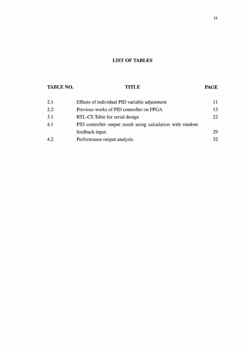
2.1 Effects of individual PID variable adjustment 112.2 Previous works of PID controller on FPGA 133.1 RTL-CS Table for serial design 224.1 PID controller output result using calculation with random
feedback input 294.2 Performance output analysis 32
X
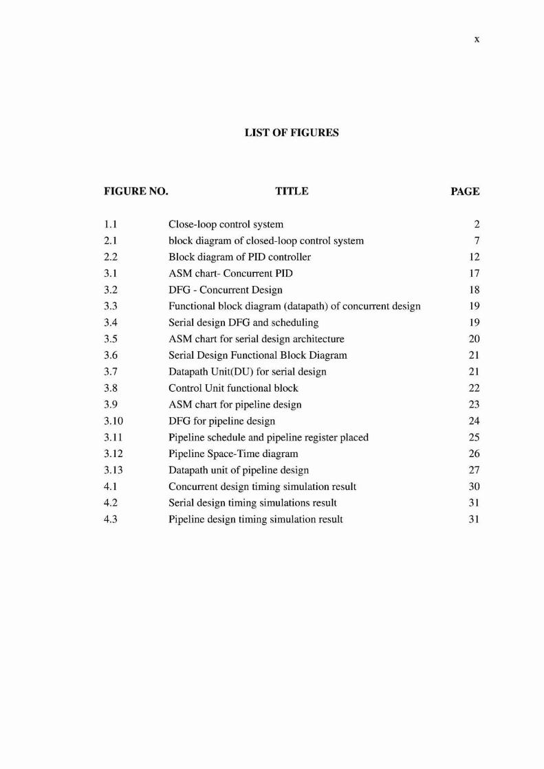
LIST OF FIGURES
FIGURE NO. TITLE PAGE
1.1 Close-loop control system 22.1 block diagram of closed-loop control system 72.2 Block diagram of PID controller 123.1 ASM chart-Concurrent PID 173.2 DFG - Concurrent Design 183.3 Functional block diagram (datapath) of concurrent design 193.4 Serial design DFG and scheduling 193.5 ASM chart for serial design architecture 203.6 Serial Design Functional Block Diagram 213.7 Datapath Unit(DU) for serial design 213.8 Control Unit functional block 223.9 ASM chart for pipeline design 233.10 DFG for pipeline design 24
3.11 Pipeline schedule and pipeline register placed 253.12 Pipeline Space-Time diagram 263.13 Datapath unit of pipeline design 274.1 Concurrent design timing simulation result 304.2 Serial design timing simulations result 314.3 Pipeline design timing simulation result 31

LIST OF ABBREVIATIONS
ASIC - Application Specific Integrated Circuit
ASM - Algorithmic State Machine
CAD - Computer Added Design
CU - Control Unit
DSP - Digital Signal Processor
DFG - Design Flow Graph
DU - Datapath Unit
FPGA - Field-Programmable Gate Array
NS - Next State
PID - Proportional-Integral-Derivative
PLC - programmable logic controller
PLD - programmable logic devices
PWM - Pulse Width Modulation
RTL - Register Tranfer Level
RTL-CS - Register Tranfer Level-Control State
VHDL - VHSIC Hardware Description Language
VHSIC - Very High Speed Integrated Circuit
CHAPTER 1
INTRODUCTION
1.1 Overview
Majority of industrial dynamic systems which utilizing digital control operate in continuous domain, rather than in discrete domain. Such systems typically
involve processing analog signals from sensors as input data to produce system output information. This requires analog-to-digital conversion. Digital control signals produced by converter then require conversion back to analog signal through digital- to-analog converter. Both process can introduce errors, delays or loses of information
which produce inaccurate control response [1].
In order to eliminate errors, increase system accuracy and produce better control response, output feedback is needed to monitor system output known as closed-
loop control [2]. Close-loop control systems widely are use in real-time embedded systems. These decision are normally made by software evaluation using feedback data from the hardware equipment under control. Proportional-Integral-Derivative (PID) control is one of the mostly used closed-loop control system and has been used in variety of applications in various industries [3]. Figure 1.1 shows a model of closed-loop control system to control servo motor. P,i and P correspond to the
control variables where P,i is desired value and P is real output value measured by sensor. The different values of P and P,i will create error signal, e(t) and «(/) is the controller output to control the device to meet desired value.

2
u(t)Closed-Loop Power ControlledController Amplifier Object P
Sensor -*
Figure 1.1: Close-loop control system
1.2 PID Controller
PID controllers have been in use and established as a key component in
industrial process control and today, over 90% industrial process are controlled by PID controllers [4]. From their simple structure design, versatility, flexibility, reliability, speed and robustness, majority of industries still rely on this controller for almost all
types of control systems.
PID controller has evolved from analog controllers using mechanical integrators and differentiator to digital controllers using programmable logic controller (PLC), microprocessor, digital signal processor (DSP) and the latest using field-
programmable gate arrays (FPGA) [5]. Digital controllers can be implemented either software based or hardware based. Digital PID controller is less expensive to implement compared to its analog version. Besides that, it is capable of utilizing
advanced control algorithm, flexible in changing its parameters and have greater insensitivity to noisy external signals.
From the topology perspective, PID controller utilizes three terms which are proportional, integral and derivative [6]. P is proportional term which correspond
to proportional control. The second term is I for integral term. This term used to control action and it is proportional to the time integral of error. This action is designed to monitor that steady state error of the system become zero. The last term
D is derivative. It is proportional to the time derivative of the control error. This feature allows system to predict the future error. Figure 1.1 shows the topology of the PID system where output signal, u[t) is the summation of proportional, integral and derivative components. There are many other variations of basic PID algorithm that improved its performance and operability.

3
1.3 Problem Statement
There are two methods to implement digital control system in digital technology. First is software implementation based approach and secondly using hardware based approach. Software-based solutions use memory-processor interactions whereby application programs will be stored in memory and at the same time, the processor proceeds to fetch, decodes, and execute the program instruction sequently. The speed of operation depend purely on software size and instruction complexity. As a result, this approach requires many cycles to execute all the
instructions and commands. Software-based implementation can be in Programmable Logic Controllers (PLC), microcontroller, microprocessors, Digital Signal Processors (DSP) and general purpose computers.
Hardware-based approach implementation previously using Application
Specific Integrated Circuit (ASIC) are utilized when system size and complexity increase. Recently, high-end FPGAs that have several million gates have given significant advantage over ASIC. Their features to assure ease of design, reduce development cost, produce extra product income and give opportunity to reduce time for product launch given superior advantage than software-based implementations. Implementation in hardware-based also produce more compact design interm of size, power efficient and high speed capabilities.
Based on significant advantage in hardware-based design, implementation of FPGA-based digital PID controller given some benefits which have better speed
performance with all operations are executed in parallel, archiving better accuracy and faster operation on FPGA.
1.4 Project Objective
Generally, this project aims to design PID controller using PID incremental
algorithm that is targeted for implementation in field-programmable gate arrays (FPGA). This aims is achieve by these two objectives.
1. The first objective is to design an RTL architecture of PID controller.
Based on PID incremental algorithm, it is simplified into its basic arithmetic operations. From this point on, a PID controller architecture design for
4
FPGA implementation has been developed. This controller architecture design
includes exploration of arithmetic operations, writing Verilog code for FPGA implementation, synthesis and simulation.
2. Second objective is to perform design space exploration of PID controller architecture. The PID controller architectures include serial, concurrent, and pipeline design. From these exploration, performance analysis is done based on simulation result.
1.5 Scope of Work
Few scopes and checklists has been identified to determine this project is planning well within given time frame. It is important to make sure the project is
done correctly and achieve their objectives.
1. The first scope is design the controller based on PID incremental algorithm. The focus of this work is to design the controller from the algorithm based on arithmetic operation which decomposed form PID incremental algorithm [4],
2. Reconstruct PID hardware architecture for implementation on an FPGA system. Architecture design is written in Verilog code and then synthesized using Altera Quartus II software before proceeding to the simulation using ModelSim from Altera.
3. PID implementation based on fixed point arithmetic and all operations in this design use real data type for a numbers.
4. For this project, the system is totally designed in software and a test bench is used to validate the design. Both RTL design and test bench are written in System Verilog programming using Altera Quartus II and Modelsim-Altera CAD tool as
logic synthesizing tool and hardware simulation tool.
5
1.6 Report Overview
This report consists of five chapters. The rest of the report is organize as follow.
1. Chapter 2 reviews existing works in literature including PID controller algorithm
and discusses several techniques and architectures on implement PID controller on FPGA. The algorithm and architecture of each technique will be examined
and explored. Several hardware architecture approaches will be compared and analyzed in this chapter.
2. Chapter 3 covers the system overview and implementation details of several
PID architectures explored in this project. This chapter describes the PID algorithm development into PID incremental algorithm and decomposed into basic arithmetic operation. Architecture development that show the hardware design steps are presented in this chapter.
3. Chapter 4 shows the result of the system output and the discussion of the system performance and limitation.
4. Finally in Chapter 5, the conclusion from this project and suggestion for future works are presented and discussed to improve PID contorller design in the future.

This document was created with W in2PDF available at h ttp://www.w in2pdf.com . The unregistered version o f W in2PDF is fo r evaluation or non-commercial use only. This page will not be added after purchasing Win2PDF.

REFERENCES
1. M. Abdelati, “FPGA-Based PID Controller Implementation,” The Islamic University o f Gaza, Palestine, 2005.
2. K. J. Astrom and T. Hagglund, “PID controllers: theory, design and tuning,” 1995.
3. M. A. Johnson and M. H. Moradi, PID control. Springer, 2005.
4. L. Rozsa, “Design and Implementation of Practical Digital PID Controllers,” in IFAC Proceedings Series, no. 15, 1990, pp. 115-121.
5. I. Grout, Digital systems design with FPGAs and CPLDs. Newnes, 2011.
6. R. Isermann, Digital control systems. Springer, 1991.
7. S. Bennett, “The past of PID controllers,” Annual Reviews in Control, vol. 25, pp. 43-53, 2001.
8. A. KRIGMAN, “Computers in process control-a panel discussion,” 1970.
9. R. C. Dorf and R. H. Bishop, “Modern control systems,” 1998.
10. D. of Scientific and I. R. GroBbritannien, Automation: a report on the technical trends and their impact on management and labour. HM Stationery Office, 1956.
11. D. Xue, Y. Chen, and D. P. Atherton, “Linear feedback control,” Analysis and
design with Matlab, Springer, 2002.
12. W. Zhao, B. H. Kim, A. C. Larson, and R. M. Voyles, “FPGA implementation of closed-loop control system for small-scale robot,” in Advanced Robotics, 2005. ICAR’05. Proceedings., 12th International Conference on. IEEE, 2005, pp. 70-77.
13. S. S. K. N. Raju, “Implementation of FPGA based PID Controller for DC
Motor Speed Control System,” in Proceedings o f the World Congress on Engineering and Computer Science, vol. 2, 2010, pp. 20-22.
14. A. Trimeche, A. Mtibaa, A. Sakly, and M. Benrejeb, PID Controller Using FPGA Technology. INTECH Open Access Publisher, 2011.

36
15. J. Lima, R. Menotti, J. M. Cardoso, and E. Marques, “A methodology to design FPGA-based PID controllers,” in Systems, Man and Cybernetics, 2006. SM C’06. IEEE International Conference on, vol. 3. IEEE, 2006, pp. 25772583.
16. S. C.Senthilsingh, “Design and Implementation of FPGA Based PID
Controller,” in International Conference on Syatem Dynamics and Control (ICSDC), 2010. ICSDC, Karnakata, India, 2010, pp. 233-236.
17. Y. Chen and Q. Wu, “Design and implementation of PID controller based on
FPGA and genetic algorithm,” in Electronics and Optoelectronics (ICEOE), 2011 International Conference on, vol. 4. IEEE, 2011, pp. V4-308.
18. V. Gupta, K. Khare, and R. Singh, “Efficient FPGA implementation of 2nd order digital controllers using MATLAB/Simulink,” Journal o f Engineering& Applied Sciences, vol. 6, no. 8, 2011.
![Sumber Manusia dan Kelebihan Daya Saing Lokasi Industri ...journalarticle.ukm.my/632/1/akademika74[01].pdf · Sumber Manusia dan Kelebihan Daya Saing Lokasi Industri Barangan ElektrikAkademika](https://static.documents.pub/doc/80x56/5c85fed109d3f289588ce4ae/sumber-manusia-dan-kelebihan-daya-saing-lokasi-industri-01pdf-sumber-manusia.jpg)


