

Engineering Data BookFile No. E06-312


1 -1
The engineering data book details all relevant data, charts and drawings toenable you to get the best performance from the Toshiba Mini-SMMS for variousapplications.
The information is aimed to assist you by providing greater system details andthe wider applications that system covers.
It is recommended that the data book be used in accordance with the followingas references.
Design manual: File No.A06-112Installation manual: File No.A06-212Service manual: File No.A05-016
(Revised 19 May 2006)


2 -1
Contents
1. Forward ...................................................................................................................... 1-1
2. Contents .................................................................................................................... 2-1
3. Introduction ............................................................................................................... 3-1
4. System overview ....................................................................................................... 4-1
4-1. Summary of system equipments ....................................................................... 4-1
4-2. Outdoor units .................................................................................................... 4-2
4-3. Indoor units ....................................................................................................... 4-3
4-4. Branching joints and headers ........................................................................... 4-5
4-5. PMV Kit ............................................................................................................. 4-5
4-6. Remote controller ............................................................................................. 4-6
5. Capacity compensation chart .................................................................................. 5-1
6. Piping requirements ................................................................................................. 6-1
7. Refrigerant cycle diagram ........................................................................................ 7-1
8. Wiring guideline ........................................................................................................ 8-1
9. Indoor unit line up ..................................................................................................... 9-1
9-1. 4-way Air Discharge Cassette Type ............................................................... 9-1-1
9-2. Compact 4-way Cassette (600 × 600) Type ................................................... 9-2-1
9-3. 2-way Air Discharge Cassette Type ............................................................... 9-3-1
9-4. 1-way Air Discharge Cassette Type (Included NewType) .............................. 9-4-1
9-5. Concealed Duct Standard Type ..................................................................... 9-5-1
9-6. Slim Duct Type ............................................................................................... 9-6-1
9-7. Concealed Duct High Static Pressure Type ................................................... 9-7-1
9-8. Under Ceiling Type ........................................................................................ 9-8-1
9-9. High Wall (1 series) Type ............................................................................... 9-9-1
9-10. High Wall (2 series) Type ............................................................................. 9-10-1
9-11. Floor Standing Cabinet Type ....................................................................... 9-11-1
9-12. Floor Standing Concealed Type .................................................................. 9-12-1
9-13. Floor Standing Type ..................................................................................... 9-13-1
9-14. Optional parts of indoor units ....................................................................... 9-14-1
10. PMV Kit .................................................................................................................... 10-1
11. Outdoor unit ............................................................................................................ 11-1
12. Controls ................................................................................................................... 12-1


World’s best class energy savings• COP of 4.61* achieved by Toshiba’s unrivalled SMMS technologies and newly developed components *When heating with 4HP CDU system
Greatest installation flexibility• 13 types of indoor units for use in up to 9 rooms; max. 6 HP
• Small and light weight outdoor unit
• Total piping length 180 m (farthest 100 m)
• Maximum height variation(Outdoor unit is up to 30 m higher than indoor unit / outdoor unit is up to 20 m lower than indoor unit)
Surprising quiet operation• Product with quiet outdoor unit by introduction of bat wing fan• Quiet operation enables a tranquil interior environment, which can be
further enhanced with our optional PMV* kit*Pulse Motor Valve
Mini-SMMS Data book
Introduction3
3 -1
1
2
3
4
5
6
7
8
9
10
11
12
Toshiba MiNi-SMMS Air Conditioning Greater Flexibility for Even More Comfort• Superior new Toshiba VRF system for small and mid-size buildings
• Toshiba’s innovative spirit and VRF concept: Advantages of the reputable SMMS technologies
(Revised 19 May 2006)

(Revised 19 May 2006)
World’s best class energy savingsCOP of 4.61* achieved by Toshiba’s unrivalled SMMS technologies and newlydeveloped components *When heating with 4HP CDU system
Vector-controlled inverter
Bat wing fan
DC fan motor• Highly efficient DC motor• 63 W+63 W output• Sine wave drive
Heat exchangerHigh-efficiency R410A heat-transfer tube
Configuration of the finned heat-transfer tube
Smooth sine curve realizes efficiency and less noise.
Efficient circuit built-in; new PIM
New development for high- pressure low-volume fan
→ The bat wing fan realizes the sound level equivalent to current model.
New
High reliability The enhanced DC twin-rotary compressor delivers stable performance with minimum friction. Ideal for noise-sensitive applications. The sound of outdoor unit is almost imperceptible.
• Low vibration
• Super-quiet operation
• High reliability
TWIN-ROTARY COMPRESSOR
DC twin-rotary compressor
Partial load range*Most frequent operation
Standard range
Tota
l eff
icie
ncy
of
com
pre
sso
r
DC twin- rotary type Conventional
rotary type
Frequency of compressor (rps)
(%)
Comparison of DC twin-rotary and conventional rotary compressor
Anti-eddy projectionMinimizes the generation of large eddies from small eddies.
Reverse-arc-shape wingReduces air turbulence due to less pressure Loss.
Toshiba Twin-Rotary Conventional Rotary Compressor
This difference is the reason for actual energy savings
3 Introduction
1
2
3
4
5
6
7
8
9
10
11
123 -2
Vector IPDU control changes the motor current wave to a smooth sinus pattern so that noise emitted from the drive units is greatly reduced.
DC driven motor with rare earth magnet· Compact· Higher efficiency· Higher power motor torque
Precise manufacturing technology in the compression parts· Higher efficiency (in wide range)· Higher reliability
Twin-rotary DC compressor

3 Introduction
Can be used with PMV kit
(Revised 19 May 2006)
New compact 4-way cassette
Line branching after header branching
Outdoor unit
Indoor unit
Branching jointHeader
Header branching after header branching
Outdoor unit
Indoor unit
Header
Header
Combination of line and header branching is highly flexible, allowing the shortest route possible thereby saving on installation time and costs. Line/header branching after header branching is only available with TOSHIBA.
Wide variety in our indoor unit line-up Shortest route design by free branching
Small and lightweight
Piping length
900 mm
117 kg228 kg1,340 mm
320 mm
1,800 mm
750 mm990 mm
1-phase3-phase
MiNi-SMMS outdoor unitSuper-MMS outdoor unit
Compact
- Line branching- Header branching - Line + Header branching
Best-in-class piping length and height
3 -3
1
2
3
4
5
6
7
8
9
10
11
12
Mini-SMMS is a result of our supreme VRF technology
Header branching after line branching
Line branching
Outdoor unit
Indoor unit
Branching joint
Outdoor unit
Indoor unit
Header

New batwing fan
DC fanmotor
Quieter soundand
power saving
DayDay NightNight
A n o p t i o n a l P M V k i t ( R B M -PMV0361E/RBM-PMV0901E) allows quiter placement to further reduce refrigerant sound.
Bat Wing fan
Night operation (sound reduction) control
PMV kit
Quieter with smoother wind flow
Die-away Zone
Suppress particular-Hz noise away Suppress overall noise levels
(Hz) (Hz)
3 Introduction
1
2
3
4
5
6
7
8
9
10
11
123 -4
(with optional PC Board (TCB-PCMO2E)) and locally supplied time/rswitch)
The unit also comes with a night-time low-noise mode, which reduces operating noise at the programmed activation time. (Timer or switch to be locally available.)
Operation control Normal Night
4HP Cooling 49 dB 46 dB
5HP Heating 50 dB 48 dB
6HP Cooling 50 dB 47 dB
Heating 52 dB 49 dB
(Revised 19 May 2006)

4 -1
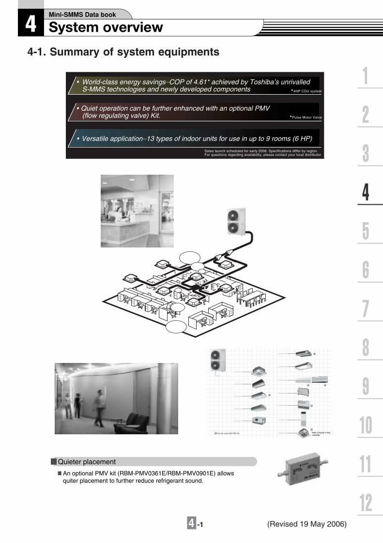
4-1. Summary of system equipments
Sales launch scheduled for early 2006. Specifications differ by region.For questions regarding availability, please contact your local distributor.
World-class energy savings_COP of 4.61* achieved by Toshiba’s unrivalled S-MMS technologies and newly developed components
Quiet operation can be further enhanced with an optional PMV (flow regulating valve) Kit.
Versatile application_13 types of indoor units for use in up to 9 rooms (6 HP)
*4HP CDU system
*Pulse Motor Valve
Quieter placement
An optional PMV kit (RBM-PMV0361E/RBM-PMV0901E) allows quiter placement to further reduce refrigerant sound.
New compact 4-way cassette
(Revised 19 May 2006)

4 -2
4-2. Outdoor units
MCY- 2DM AP H T
Corresponding HP
Modelname
Heat pump(50Hz) MCY-
Heat pump(60Hz) MCY-
Cooling capacity(kW)*1
Heating capacity(kW)*1
No.of connectable indoor units
Inverter unit
4HP 5HP 6HP
MAP0401HT MAP0501HT MAP0601HT
MAP0401HT2D MAP0501HT2D MAP0601HT2D
12.1
12.5
6
14.0
16.0
8
15.5
18.0
9
*1 Rated conditions Cooling:Indoor air temperature 27oC DB/19oCWB,Outdoor air temperature 35oCDB Heating:Indoor air temperature 20oC DB,Outdoor air temperature 7oCDB/6oCWB
Allocation standard of model name
No mark: Power supply specification, 1O/ 220-240V, 50Hz2D : Power supply specification, 1O/ 220V, 60Hz
T : Inverter unit
H : Heat pump
Development Number
Capacity rank HP x 10
R410A
M : Individual unit
Multi Compact Type
4 -3
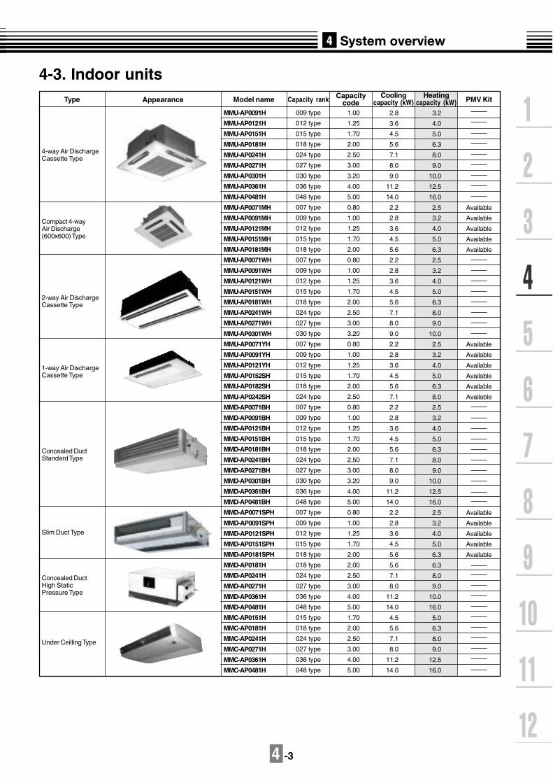
Type Appearance Model name Capacity rank Capacitycode
Coolingcapacity (kW)
Heatingcapacity (kW)
4-way Air DischargeCassette Type
2-way Air DischargeCassette Type
1-way Air DischargeCassette Type
Slim Duct Type
Concealed DuctStandard Type
Concealed DuctHigh StaticPressure Type
Under Ceilling Type
PMV Kit
Compact 4-wayAir Discharge(600x600) Type
MMU-AP0091H
MMU-AP0121H
MMU-AP0151H
MMU-AP0181H
MMU-AP0241H
MMU-AP0271H
MMU-AP0301H
MMU-AP0361H
MMU-AP0481H
MMU-AP0071MH
MMU-AP0091MH
MMU-AP0121MH
MMU-AP0151MH
MMU-AP0181MH
MMU-AP0071WH
MMU-AP0091WH
MMU-AP0121WH
MMU-AP0151WH
MMU-AP0181WH
MMU-AP0241WH
MMU-AP0271WH
MMU-AP0301WH
MMU-AP0071YH
MMU-AP0091YH
MMU-AP0121YH
MMU-AP0152SH
MMU-AP0182SH
MMU-AP0242SH
MMD-AP0071BH
MMD-AP0091BH
MMD-AP0121BH
MMD-AP0151BH
MMD-AP0181BH
MMD-AP0241BH
MMD-AP0271BH
MMD-AP0301BH
MMD-AP0361BH
MMD-AP0481BH
MMD-AP0071SPH
MMD-AP0091SPH
MMD-AP0121SPH
MMD-AP0151SPH
MMD-AP0181SPH
MMD-AP0181H
MMD-AP0241H
MMD-AP0271H
MMD-AP0361H
MMD-AP0481H
MMC-AP0151H
MMC-AP0181H
MMC-AP0241H
MMC-AP0271H
MMC-AP0361H
MMC-AP0481H
009 type
012 type
015 type
018 type
024 type
027 type
030 type
036 type
048 type
007 type
009 type
012 type
015 type
018 type
007 type
009 type
012 type
015 type
018 type
024 type
027 type
030 type
007 type
009 type
012 type
015 type
018 type
024 type
007 type
009 type
012 type
015 type
018 type
024 type
027 type
030 type
036 type
048 type
007 type
009 type
012 type
015 type
018 type
018 type
024 type
027 type
036 type
048 type
015 type
018 type
024 type
027 type
036 type
048 type
1.00
1.25
1.70
2.00
2.50
3.00
3.20
4.00
5.00
0.80
1.00
1.25
1.70
2.00
0.80
1.00
1.25
1.70
2.00
2.50
3.00
3.20
0.80
1.00
1.25
1.70
2.00
2.50
0.80
1.00
1.25
1.70
2.00
2.50
3.00
3.20
4.00
5.00
0.80
1.00
1.25
1.70
2.00
2.00
2.50
3.00
4.00
5.00
1.70
2.00
2.50
3.00
4.00
5.00
2.8
3.6
4.5
5.6
7.1
8.0
9.0
11.2
14.0
2.2
2.8
3.6
4.5
5.6
2.2
2.8
3.6
4.5
5.6
7.1
8.0
9.0
2.2
2.8
3.6
4.5
5.6
7.1
2.2
2.8
3.6
4.5
5.6
7.1
8.0
9.0
11.2
14.0
2.2
2.8
3.6
4.5
5.6
5.6
7.1
8.0
11.2
14.0
4.5
5.6
7.1
8.0
11.2
14.0
3.2
4.0
5.0
6.3
8.0
9.0
10.0
12.5
16.0
2.5
3.2
4.0
5.0
6.3
2.5
3.2
4.0
5.0
6.3
8.0
9.0
10.0
2.5
3.2
4.0
5.0
6.3
8.0
2.5
3.2
4.0
5.0
6.3
8.0
9.0
10.0
12.5
16.0
2.5
3.2
4.0
5.0
6.3
6.3
8.0
9.0
10.0
16.0
5.0
6.3
8.0
9.0
12.5
16.0
Available
Available
Available
Available
Available
Available
Available
Available
Available
Available
Available
Available
Available
Available
Available
Available
4-3. Indoor units

4 -4
- -AP HMM
Allocation standard of model name
M : Compact 4-way Cassete TypeW : 2-way Cassete TypeS : 1-way Cassete TypeY : Small sized 1-way Cassete TypeB : Built-in Type (Built-in Duct Type) (Floor concealed Type)SP(S) : Slim Duct Type
C : China model
U : Cassette TypeD : Duct TypeC : Under Ceiling TypeK : High Wall TypeL : Floor Type (Cabinet type) (Concealed type)F : Floor Standing Type
Development series No.
Based on the cooling capacity (Btu/h)/1,000
R410A
MM : Modular Multi Type
PMV Kit
007 type
009 type
012 type
015 type
018 type
024 type
007 type
009 type
012 type
007 type
009 type
012 type
015 type
018 type
024 type
007 type
009 type
012 type
015 type
018 type
024 type
015 type
018 type
024 type
027 type
036 type
048 type
Type Appearance Model name Capacityrank
Capacitycode
Coolingcapacity (kW)
Heatingcapacity (kW)
Floor StandingCabinet Type
Floor StandingConcealed Type
Floor Standing Type
MMK-AP0071H
MMK-AP0091H
MMK-AP0121H
MMK-AP0151H
MMK-AP0181H
MMK-AP0241H
MMK-AP0072H
MMK-AP0092H
MMK-AP0122H
MML-AP0071H
MML-AP0091H
MML-AP0121H
MML-AP0151H
MML-AP0181H
MML-AP0241H
MML-AP0071BH
MML-AP0091BH
MML-AP0121BH
MML-AP0151BH
MML-AP0181BH
MML-AP0241BH
MMF-AP0151H
MMF-AP0181H
MMF-AP0241H
MMF-AP0271H
MMF-AP0361H
MMF-AP0481H
0.80
1.00
1.25
1.70
2.00
2.50
0.80
1.00
1.25
0.80
1.00
1.25
1.70
2.00
2.50
0.80
1.00
1.25
1.70
2.00
2.50
1.70
2.00
2.50
3.00
4.00
5.00
2.2
2.8
3.6
4.5
5.6
7.1
2.2
2.8
3.6
2.2
2.8
3.6
4.5
5.6
7.1
2.2
2.8
3.6
4.5
5.6
7.1
4.5
5.6
7.1
8.0
11.2
14.0
2.5
3.2
4.0
5.0
6.3
8.0
2.5
3.2
4.0
2.5
3.2
4.0
5.0
6.3
8.0
2.5
3.2
4.0
5.0
6.3
8.0
5.0
6.3
8.0
9.0
10.0
16.0
High Wall Type(2 series)
High Wall Type(1 series)
Available
Available
Available
Available
Available
Available
Available
Available
Available
Available
Available
Available
Available
Available
Available

4 -5
4-4. Branching joints and headers *1
*1 If total capacity code value of indoor unit exceeds that of outdoor unit, apply code of outdoor unit.*2 "capacity code" can be obtained from page 5-1. (capacity code is not actual capacity)*3 When using Y-shape branching joint for 1st branching, select according to the capacity code of outdoor unit.
Model name
Usage Appearance
Y-shape branching joint
4-branching header
8-branching header
RBM-BY53E
RBM-HY1043E
RBM-HY1083E
Indoor unit capacity code (*2) :Total below 7.8
Indoor unit capacity code (*2) :Total below 7.8
Indoor unit capacity code (*2) :Total below 7.8
4-5. PMV Kit
Indoor unit capacity type Appearance
RBM-PMV0361E
RBM-PMV0901E
007, 009, 012 type
015, 018, 024 type
For more information see Chapter 10.
Model name
(Revised 12 July 2006)
4 -6
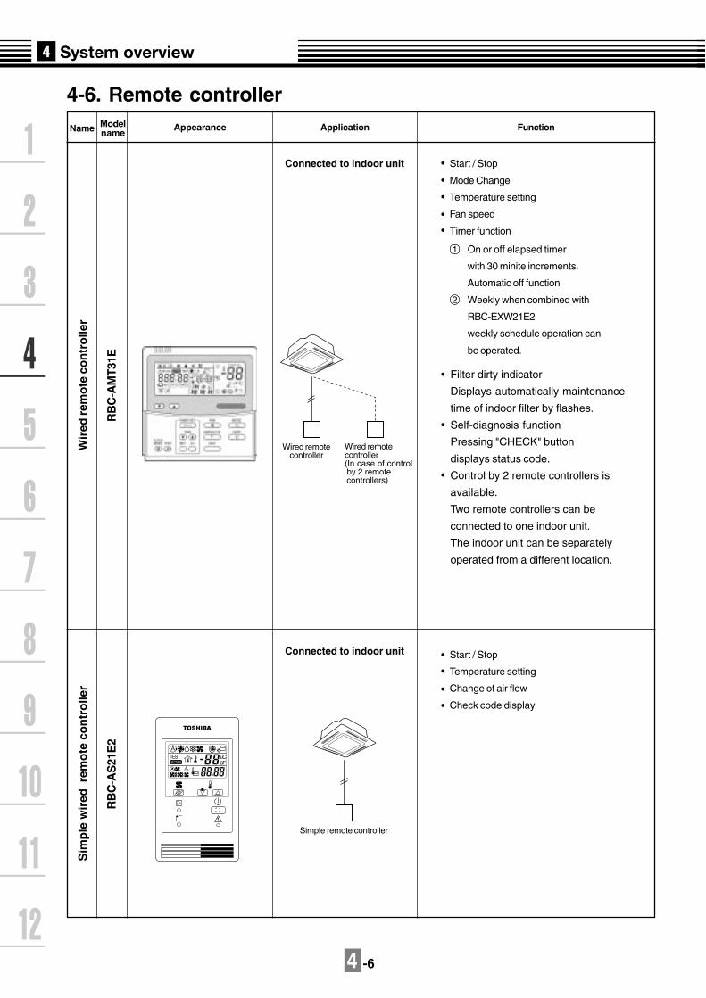
4-6. Remote controller
Name Modelname
Appearance Application Function
Wir
ed r
emo
te c
on
tro
ller
Sim
ple
wir
ed r
emo
te c
on
tro
ller
RB
C-A
S21
E2
RB
C-A
MT3
1E
Connected to indoor unit
Connected to indoor unit
Simple remote controller
Wired remotecontroller
Wired remotecontroller(In case of control by 2 remote controllers)
Start / Stop
Mode Change
Temperature setting
Fan speed
Timer function
Filter dirty indicator
Displays automatically maintenance
time of indoor filter by flashes.
Self-diagnosis function
Pressing "CHECK" button
displays status code.
Control by 2 remote controllers is
available.
Two remote controllers can be
connected to one indoor unit.
The indoor unit can be separately
operated from a different location.
1
2
Start / Stop
Temperature setting
Change of air flow
Check code display
On or off elapsed timer
with 30 minite increments.
Automatic off function
Weekly when combined with
RBC-EXW21E2
weekly schedule operation can
be operated.
ûCûF
TESTSETTING

4 -7
Wir
eles
s re
mo
te c
on
tro
ller
kit
TCB
-AX
21E
2R
BC
-AX
22C
E2
TCB
-AX
21U
(W)-
E2
Name Modelname
Appearance Function
Start / Stop
Mode change
Temperature setting
Change of air flow
Timer function
On or off timer operation, setting in
30 minute increments.
Automatic Off function
Control by 2 remote controllers is
available.
Two wireless remote controllers can
operate one indoor unit. The indoor unit
can be separately operated from a
different location.
Check code display
TCB-AX21U(W)-E2
(for 4-way airdischarge cassette)
RBC-AX22CE2
(for under ceiling)
TCB-AX21-E2
(for other units except for the con-
cealed duct high static pressure)

4 -8
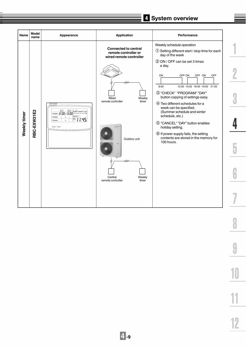
Name Modelname Appearance Application Performance
Cen
tral
rem
ote
co
ntr
olle
r
TCB
-SC
642T
LE2
Connected to outdoor unit,or indoor unit
Outdoorunit
Centralremote controller
Indoorremote controller
Centralremote
controller
Individual control up to 64 indoor units.
Individual control for max. 64 indoorunits divided into 4 zones.
Up to 16 indoor units for eachzone
Up to 16 outdoor units areconnectable.
Four selectable central control settings torestrict individual remote controlleroperations.
Setting for one of 1 to 4 zones isavailable.
Can be used with other central controldevices (Up to 10 central controldevices with in one control circuit)
Two selectable control modesCentral controller modeRemote controller mode
Setting of simultaneous ON/OFF 3times for each day of the weekcombined with a weekly timer.
ON
-OF
F c
on
tro
ller
TCB
-CC
163T
LE2
Connected to outdoor unit,or indoor unit
Indoor unit
Indoorremote controller
Outdoor unit
ON-OFFcontroller
ON-OFFcontroller
Setting of simultaneous ON-OFF 3 times for each day of the week when combined with a weekly timer.
Individual control up to 16 indoor units.
Connected to 2 remote controllers ispossible.
SELECT ZONE
CL SET
GROUP
CODE No.
UNIT No.
No.R.C.
TEST
ZONEALLZONEGROUP
SETTING
1234
SET DATA
4 -9
Name
Wee
kly
tim
er
Modelname Appearance Application Performance
RB
C-E
XW
21E
2
Connected to centralremote controller or
wired remote controller
Wiredremote controller
Weeklytimer
Outdoor unit
Centralremote controller
Weeklytimer
Weekly schedule operation
Setting different start / stop time for eachday of the week
ON / OFF can be set 3 timesa day.
1
2
3
Two different schedules for aweek can be specified.(Summer schedule and winterschedule, etc.)
4
5
If power supply fails, the settingcontents are stored in the memory for100 hours.
6
"CHECK" "PROGRAM" "DAY"button copying of settings easy.
"CANCEL" "DAY" button enablesholiday setting.WEEKLY TIMER
ERROR
SuMoTuWeTh Fr SaPROGRAM1
PROGRAM2
PROGRAM3
ON
8:00 12:00 13:00 18:00 19:00 21:00
OFF ON OFF ON OFF


5 -1
For indoor unit, the capacity code is decided for each capacity rank.
NOTE :
Capacity rank : Correspondence to Btu/h. Capacity code : Correspondence to Horsepower.
For outdoor unit, maximum No. of connectable indoor units and total capacity code of indoor unitsare decided.
Capacity rank type
Capacity code
007
0.8
009
1
012
1.25
015
1.7
018
2
024
2.5
030
3.2
036
4
048
5
027
3
Outdoor unitCapacity code of
outdoor unitMax. No. of
indoor unitsTotal capacity code
of indoor units
MCY-MAP0401HTMCY-MAP0401HT2D 4
5
6
6
8
9
3.2 to 5.2
4.0 to 6.5
4.8 to 7.8
1
2
5-1. Cooling/heating capacity characteristics
Cooling capacity calculation method :Required cooling capacity = Cooling capacity x Factor ( , , , , *1) kW
Indoor air wet bulb temperature vs. capacity correction value
1
Indoor air wet bulb temp. (oC)
Cap
acity
cor
rect
ion
valu
e
15
1.2
1.1
1.0
0.9
0.820 24
Outdoor air dry bulb temperature vs.capacity correction value
Indoor air wet bulb temp. (oC)
Cap
acity
cor
rect
ion
valu
e
15
1.2
1.1
1.0
0.9
0.820 24
(Example)Design Outdoor conditions : 17oC DB Capacity correction value : 1.14
Outdoor air dry bulb temp. (oC)Cap
acity
cor
rect
ion
valu
e
-5 0 5 10 15 20 25 30 35 40 430.9
1
1.1
1.2
Outdoor air dry bulb temp. (oC)Cap
acity
cor
rect
ion
valu
e
-5 0 5 10 15 20 25 30 35 40 430.9
1
1.1
1.2
MCY-MAP0501HTMCY-MAP0501HT2DMCY-MAP0601HTMCY-MAP0601HT2D
(Example)Design Indoor conditions : 22oC WB Capacity correction value : 1.09
*1 : Coefficient to use for correction of outdoor unit capacity when total capacity of the indoorunits are not equal to the outdoor unit capacity.
5 -2
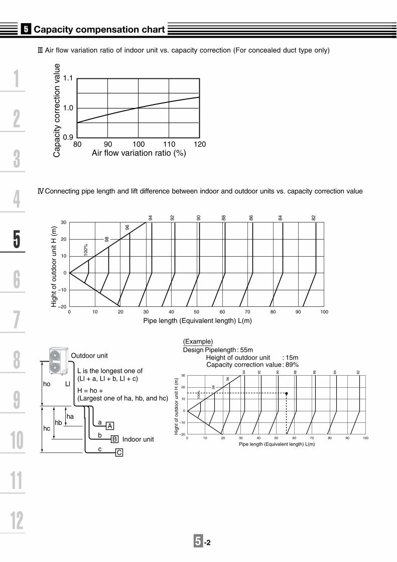
Air flow variation ratio of indoor unit vs. capacity correction (For concealed duct type only)C
apac
ity c
orre
ctio
n va
lue
1.1
1.0
0.980 90 100 110 120
Air flow variation ratio (%)
30
20
10
0
-10
-200 10 20 30 40
Pipe length (Equivalent length) L(m)
Hig
ht o
f out
door
uni
t H (
m)
50 60 70 80 90 100
100%
98
96
94 92 90 88 86 84 82
Outdoor unit
Indoor unit
L is the longest one of (Ll + a, Ll + b, Ll + c)
H = ho + (Largest one of ha, hb, and hc)
Aha
hbhc
ho Ll
a
b
cB
C
30
20
10
0
-10
-200 10 20 30 40
Pipe length (Equivalent length) L(m)
Hig
ht o
f out
door
uni
t H (
m)
50 60 70 80 90 100
100%
98
96
94 92 90 88 86 84 82
(Example)Design Pipelength : 55m Height of outdoor unit : 15m Capacity correction value: 89%
Connecting pipe length and lift difference between indoor and outdoor units vs. capacity correction value

5 -3
Correction of outdoor unit diversity
Heating capacity calculation method :Required heating capacity = Heating capacity x Factor ( , , , , *1, *2) kW
Indoor air dry bulb temperature vs. capacity correction value
Outdoor air wet bulb temperature vs. capacity correction value
2
Indoor air dry bulb temp. (oC)
Cap
acity
cor
rect
ion
valu
e
0.815 20 24
0.9
1.0
1.1
1.2
(Example)Design Outdoor unit : 5.0HP Indoor units total capacity : 5.5HP (Capacity ratio : 110%) Capacity correction value : 1.03%
Indoor air dry bulb temp. (oC)
Cap
acity
cor
rect
ion
valu
e
0.815 20 24
0.9
1.0
1.1
1.2
(Example)Design Indoor conditions : 21.5oC DB Capacity correction value : 0.98
(Example)Design Outdoor conditions : -5oC WB Capacity correction value : 0.8
Outdoor air wet bulb temp. (oC)
Cap
acity
cor
rect
ion
valu
e
1.2
1.1
1
0.9
0.8
0.7
0.6
0.5
-15 -10 -5 0 5 10 15
Outdoor air wet bulb temp. (oC)
Cap
acity
cor
rect
ion
valu
e
1.2
1.1
1
0.9
0.8
0.7
0.6
0.5
-15 -10 -5 0 5 10 15
1.1
1
0.9
0.8
0.7
80 80 100 110 120 130
Cap
acity
cor
rect
ion
valu
e
Indoor units total capacity ratio (%)Standard capacity ratio
1.1
1
0.9
0.8
0.7
80 80 100 110 120 130
Cap
acity
cor
rect
ion
valu
e
Indoor units total capacity ratio (%)Standard capacity ratio
*1 : Coefficient to use for correction of outdoor unit capacity when total capacity of the indoorunits are not equal to the outdoor unit capacity.
*2 : Refer to item 3.

5 -4
Air flow variation ratio of indoor unit vs. capacity correction (For concealed duct type only)C
apac
ity c
orre
ctio
n va
lue
Air flow variation ratio (%)
0.9
1.0
1.1
80 90 100 110 120
Connecting pipe length and lift difference between indoor and outdoor units vs. capacity correction value
Pipe length (Equivalent length) L (m)
Hei
ght o
f out
door
uni
t H (
m)
30
99
98
97 96 95 94
20
10
0
-10
-200 10 20 30 40 50 60 70 80 90 100
100%
Outdoor unit
Indoor unit
L is the longest one of (Ll + a, Ll + b, Ll + c)
H = ho + (Largest one of ha, hb, and hc)
Aha
hbhc
ho Ll
a
b
cB
CPipe length (Equivalent length) L (m)
Hei
ght o
f out
door
uni
t H (
m)
30
99
98
97 96 95 94
20
10
0
-10
-200 10 20 30 40 50 60 70 80 90 100
100%
(Example)Design Pipe length : 75m Heigh of outdoor unit : 15m Capacity correction value : 95.1%
5 -5
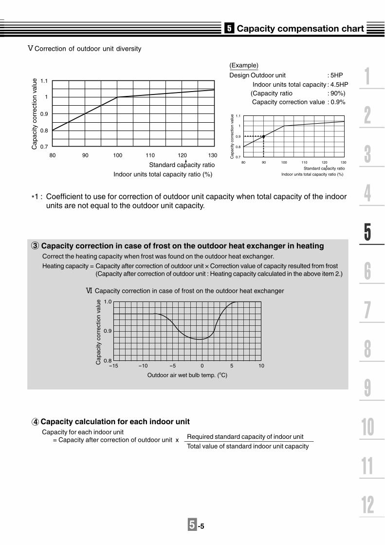
Correction of outdoor unit diversity
*1 : Coefficient to use for correction of outdoor unit capacity when total capacity of the indoorunits are not equal to the outdoor unit capacity.
Capacity correction in case of frost on the outdoor heat exchanger in heatingCorrect the heating capacity when frost was found on the outdoor heat exchanger.
Heating capacity = Capacity after correction of outdoor unit × Correction value of capacity resulted from frost(Capacity after correction of outdoor unit : Heating capacity calculated in the above item 2.)
3
0.8
0.9
1.0
-15 -10 -5 0 5 10
Outdoor air wet bulb temp. (oC)
Cap
acity
cor
rect
ion
valu
e
Capacity correction in case of frost on the outdoor heat exchanger
Capacity calculation for each indoor unitCapacity for each indoor unit
= Capacity after correction of outdoor unit x Required standard capacity of indoor unit
Total value of standard indoor unit capacity
4
(Example)
Design Outdoor unit : 5HP
Indoor units total capacity : 4.5HP (Capacity ratio : 90%) Capacity correction value : 0.9%
1.1
1
0.9
0.8
0.7
80 90 100 110 120 130
Cap
acity
cor
rect
ion
valu
e
Indoor units total capacity ratio (%)
Standard capacity ratio
1.1
1
0.9
0.8
0.7
80 90 100 110 120 130
Cap
acity
cor
rect
ion
valu
e
Indoor units total capacity ratio (%)
Standard capacity ratio
5 -6
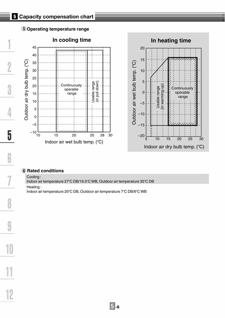
Rated conditionsCooling :Indoor air temperature 27oC DB/19.0oC WB, Outdoor air temperature 35oC DB
Heating :Indoor air temperature 20oC DB, Outdoor air temperature 7oC DB/6oC WB
5
6
Operating temperature range
3025 28201510-10
-5
0
5
10
15
20
25
30
35
40
45
Indoor air wet bulb temp. (oC)
In cooling time
Out
door
air
dry
bulb
tem
p. (
o C)
Continuously operable
rangeU
sabl
e ra
nge
(in p
ull d
own)
Indoor air dry bulb temp. (oC)
In heating time
Out
door
air
wet
bul
b te
mp.
(o C
)-20
-15
-10
-5
0
5
10
15
20
5 10 15 20 25 30
Continuously operable
range
Usa
ble
rang
e (in
war
min
g-up
)


6 -1
Linebranchingsystem
Headerbranchingsystem
Headerbranchingsystemafter linebranching
Linebranchingsystem afterheaderbranching
Headerbranchingsystem afterheaderbranching
6-1. Free branching systemLine branching system
Header branching system
Header branching system after line branching
Line branching system after header branching
Header branching system after header branching
The above five branching systems are available to dramatically increase the flexibility of refrigerant piping design.
1
2
3
4
5
Outdoor unit
Branching joint
Remotecontroller
Indoor unit
Branching header
Remote controller
Indoor unit
Outdoor unit
Branching joint
Remotecontroller
Indoor unit
PMVKit
Branching header
Outdoor unit
Branching joint
Remotecontroller
Indoorunit
Branching header
Outdoor unit
PMVKit
* In case of "PMV Kit"
* In case of "PMV Kit"

6 -2
6-2. Refrigerant piping length and piping size
A
Outdoor unit
Mainpipe
Branching header
Branchingpipe
HeightdifferencebetweenIndoor andoutdoor unit
Equivalent length corresponded to farthest piping
Equivalent length corresponded to farthest piping after 1st branching Li
Indoor unit
Y-shapebranching joint
Height differencebetween indoor units
1st branchingsection
L2
L3
L4
L
e fg
H1H2
L1
a b c d
Branching pipe
Allowable length and height difference of refrigerant piping1

6 -3
Allowable length and height difference of refrigerant piping
Allowable value Piping section
PipingLength
HeightDifference
Total extension of pipe(Liquid pipe, real length)
Furthest piping length L(*1)
Real length
Equivalentlength
Max.equivalent length ofmain pipe
Equivalent length of furthestpiping from 1st branchingLi (*1)
Max.real length of indoorunit connecting pipe
Height between indoor andoutdoor units H1
Upper outdoorunit
Lower outdoorunit
Height between indoor units H2
180m
100m
125m
65m
35m
15m
30m
20m
15m
L1+L2+L3+L4+a+b+c+d+e+f+g
L1+L3+L4+g
L1
L3+L4+g
a, b, c, d, e, f, g
_
_
_
*1 Furthest indoor unit from 1st branch to be named "A"
1

6 -4
Gas pipeLiquid pipe
1st branchingsection Branching
pipeBranching header
Indoor unit
Indoor unit
Branchingpipe
Y-shapeBranching joint
Outdoor unit
Mainpipe
14 2 4
33
3 3 3
2 24 4
3 3
Selection of refrigerant piping2

6 -5
Selection of refrigerant piping (cont.)
No. Piping parts Name Selection of pipe size
2
1
2
3
4
Outdoor unit
1st branchingsection
Branchingsection
Branchingsection
Branchingsection
Indoor unit
Branchingsection
Main pipe
Branchingpipe
Indoor unit
connectingpipe
Y-shapebranching joint
Branchingheader
Size of main pipe
Outdoor unit capacity type
0401 type
0501 type
0601 type
Gas pipe (mm)
15.9
15.9
19.1
Liquid pipe (mm)
9.5
9.5
9.5
Pipe size between branching sections
Total capacity codes of indoor units at down stream side Gas pipe(mm)
Liquid pipe(mm)Equivalent to HP
Below 2.8
2.8 to below 6.4
6.4 to below 7.2
12.7
15.9
19.1
9.5
9.5
9.5
Note) If the total capacity code value of indoor units exceeds that of the outdoor units, apply the capacity code of outdoor units.
Connecting pipe size of indoor unit
Indoor unit capacity type
007, 009, 012 type
015, 018 type
024, 030, 036, 048 type
Gas pipe (mm)
9.5
12.7
15.9
Liquid pipe (mm)
6.4
6.4
9.5
Selection of branching section
Total capacity codes of indoor units at down stream side
Equivalent to HP
Below 7.8
Below 7.8
Below 7.8
Model name
RBM-BY53E
RBM-HY1043E
RBM-HY1083E
Y-shape branching joint
Note) *1 : For 1 line after branching header indoor units with a maximum capacitycode of 6.0 in total can be connected.
Minimum wall thickness for R410A application
Soft Harf Hardor Hard
OD(inch)
OD(mm)
Minimum wallthickness (mm)
OK
OK
OK
OK
NG*
OK
OK
OK
OK
OK
1/4"
3/8"
1/2"
5/8"
3/4"
6.35
9.52
12.70
15.88
19.05
0.80
0.80
0.80
1.00
1.00*If the pipe size is O/ 19.0 or more, use a suitable material.
Branchingheader*1
For 4 branches
For 8 branches
(Revised 12 July 2006)

6 -6
6-3. Refrigerant piping length and piping size with PMV Kit
Allowable length and height difference of refrigerant piping1
A
Outdoor unit
Mainpipe
Branching header
PMV Kit
Branchingpipe
HeightdifferencebetweenIndoor andoutdoor unit
Equivalent length corresponded to farthest piping
Equivalent length corresponded to farthest piping after 1st branching
Indoor unit
Y-shapeBranching joint
Height differencebetween indoor units
(PMV Kit)
1st branchingsection
L2
L3
L4
L
Li
e f
l m n
g
H1H2
L1
a
h i j k
b c d
Branching pipe

6 -7
Allowable length and height difference of refrigerant piping
Allowable value Piping section
PipingLength
HeightDifference
Total extension of pipe(Liquid pipe, real length)
Furthest piping length L(*1)
Real length
Equivalentlength
Equivalent length of furthestpiping from 1st branching Li(*1)
Height between indoor andoutdoor unit H1
Upper outdoorunit
Lower outdoorunit
150m
65m
80m
15m
30m
20m
15m
L1+L2+L3+L4+a+b+c+d+e+f+g+h+i+j+k+l+m+n
L1+L3+L4+g+n
L1
L3+L4+g+n
a+h, b+i, c+j, d+k, e+l, f+m, g+n
_
_
_
*1 Furthest indoor unit from 1st branch to be named "A"
1
h, i, j, k, l, m, n
NOTEDon,t connect two or more indoor units to one PMV Kit. Arrange one indoor unit and one PMV Kit set to 1 by 1.
PMVKit
Not Available AvailablePMVKit
Indoor unit Indoor unit
2m or moreand up to 10m
Height between indoor units (PMV Kit) H2Height difference between highest indoor unit or PMV Kit andlowest indoor unit or PMV Kit shall be 15m or less
50mMax.equivalent length of main pipe
15mMax.real length of indoor unit connecting pipe
Real length between PMV Kit and indoor unit

6 -8
Selection of refrigerant piping2
Gas pipeLiquid pipe
1st branchingsection Branching
pipeBranching header
Indoor unit
Indoor unit
Branchingpipe
Y-shapeBranching joint
Outdoor unit
Mainpipe
14 2 4
33
5 5
5 5 5
5 5
3 3 3
2 24 4
3 3
PMV Kit

6 -9
Selection of refrigerant piping (cont.)
No. Piping parts Name Selection of pipe size
2
1
2
3
4
Outdoor unit
1st branchingsection
Branchingsection
Branchingsection
Branchingsection
Indoor unit
Branchingsection
Main pipe
Branchingpipe
Indoor unit
connectingpipe
Y-shapebranching joint
Branchingheader
Size of main pipe
Outdoor unit capacity type
0401 type
0501 type
0601 type
Gas pipe (mm)
15.9
15.9
19.1
Liquid pipe (mm)
9.5
9.5
9.5
Pipe size between branching sections
Total capacity codes of indoor units at down stream side Gas pipe(mm)Equivalent to HP
Below 2.8
2.8 to below 6.4
6.4 to below 7.2
12.7
15.9
19.1
Note) If the total capacity code value of indoor units exceeds that of the outdoor units, apply the capacity code of outdoor units.
Connecting pipe size of indoor unit
Indoor unit capacity type
007, 009, 012 type
015, 018 type
024 type
Gas pipe (mm)
9.5
12.7
15.9
Liquid pipe (mm)
6.4
6.4
9.5
Minimum wall thickness for R410A application
Soft Harf Hardor Hard
OD(inch)
OD(mm)
Minimum wallthickness (mm)
OK
OK
OK
OK
NG*
OK
OK
OK
OK
OK
1/4"
3/8"
1/2"
5/8"
3/4"
6.35
9.52
12.70
15.88
19.05
0.80
0.80
0.80
1.00
1.00
*If the pipe size is O/ 19.0 or more, use a suitable material as detailed in the installation manual.
5 PMV Kit PMV Kit
Selection of PMV Kit
Indoor unit capacity type
007, 009, 012 type
015, 018, 024 type
Model name
RBM-PMV0361E
PBM-PMV0901E
Liquid pipe(mm)
9.5
9.5
9.5
Selection of branching section
Total capacity codes of indoor units at down stream side
Equivalent to HP
Below 7.8
Below 7.8
Below 7.8
Model name
RBM-BY53E
RBM-HY1043E
RBM-HY1083E
Y-shape branching joint
Note) *1 : For 1 line after branching header indoor units with a maximum capacitycode of 6.0 in total can be connected.
Branchingheader*1
For 4 branches
For 8 branches
(Revised 12 July 2006)

6 -10
6-4. Refrigerant piping example
In case of without "PMV Kit"1
Outdoor unitMCY-MAP0601HT
Mainpipe
Branching pipe
Branching header
Branching pipe
Indoor unit
MMU-AP0071MH
MMU-AP0151H
MMU-AP0241H
MMU-AP0091H MMU-AP0701MH MMU-AP0701MH
Y-shapeBranching joint
Capacitycode
1st branchingsection
L3
L1
(3.4)(7.6)
(0.8) (1.0) (0.8) (0.8)
(2.5)
(4.2)12m
(1.7)
=60m
L2 =7m
=1m
=20m
a
=4me
=10mf
=6mb =8mc =15md10m
1
3
2

6 -11
Mark
Piping size
Equivalent length(m)
Seclection method(capacity code)
Gas pipe(mm)
Liquid pipe(mm)
L1
L2
L3
a
b
c
d
e
f
60
7
20
1
6
8
15
4
10
0.8 + 1.0 + 0.8 + 0.8 = 3.4
1.7 + 2.5 = 4.2
0.8
1.0
0.8
0.8
1.7
2.5
O/ 19.1
O/ 15.9
O/ 15.9
O/ 9.5
O/ 9.5
O/ 9.5
O/ 9.5
O/ 12.7
O/ 15.9
O/ 9.5
O/ 9.5
O/ 9.5
O/ 6.4
O/ 6.4
O/ 6.4
O/ 6.4
O/ 6.4
O/ 9.5
Y-shape branching joint and Header
MarkY-joint or Header select
(capacity code)Model name
1st branching
Branch header
Y-shape branch joint
6(capacity code of outdoor unit)
0.8 +1.0 +0.8 +0.8 = 3.4(a+b+c+d=L2)
1.7 + 2.5 = 4.2(e+f=L3)
RBM-BY53E
RBM-HY1043E
RBM-BY53E
1
2
3

6 -12
In cace of PMV Kit2
Outdoor unitMCY-MAP0601HT
Mainpipe
Branching pipe
Branching header
Branching pipe
Indoor unit
MMU-AP0071MH
MMU-AP0151H
MMU-AP0241H
MMU-AP0091H MMU-AP0701MH MMU-AP0701MH
Y-shapeBranching joint PMV Kit
Capacitycode
1st branchingsection
L3
L1
(3.4)(7.6)
(0.8) (1.0) (0.8) (0.8)
(2.5)
(4.2)12m
(1.7)
=20m
L2 =3m
=4m
=6m
a
=4me
=6mf
=3mb =6mc =7md10m
1
3
2

6 -13
Mark
Piping size
Equivalent length(m)
Seclection method(capacity code)
Gas pipe(mm)
Liquid pipe(mm)
L1
L2
L3
a
b
c
d
e
f
20
3
6
4
3
6
7
4
6
0.8 + 1.0 + 0.8 + 0.8 = 3.4
1.7 + 2.5 = 4.2
0.8
1.0
0.8
0.8
1.7
2.5
O/ 19.1
O/ 15.9
O/ 15.9
O/ 9.5
O/ 9.5
O/ 9.5
O/ 9.5
O/ 12.7
O/ 15.9
O/ 9.5
O/ 9.5
O/ 9.5
O/ 6.4
O/ 6.4
O/ 6.4
O/ 6.4
O/ 6.4
O/ 9.5
Y-shape branching joint and Header
MarkY-joint or Header select
(capacity code)Model name
1st branching
Branch header
Y-shape branch joint
6(capacity code of outdoor unit)
0.8 +1.0 +0.8 +0.8 = 3.4(a+b+c+d=L2)
1.7 + 2.5 = 4.2(e+f=L3)
RBM-BY53E
RBM-HY1043E
RBM-BY53E
1
2
3
Mark
PMV Kit
PMV Kit select(capacity code)
Model name
0.8
1.0
0.8
0.8
1.7
2.5
RBM-PMV0361E
RBM-PMV0361E
RBM-PMV0361E
RBM-PMV0361E
RBM-PMV0901E
RBM-PMV0901E

6 -14
6-5. Charging requirement with additional refrigerant
(Calculation)Additional refrigerant charge amount is calculated from size of liquid pipe at site and its real length.
After the system has been vacuumed,replace the vacuum pumpwith a refrigerant cylinder and charge the systemwith additional refrigerant.
Additional refrigerantcharge amount at site
Additional refrigerant chargeamount per liquid pipe 1m (Table 1)
Compensation byoutdoor HP (Table 2)
Real length ofliquid pipeR (kg) X= +
Table 1
Pipe dia. at liquid sideAdditional refrigerant amount/1m (kg)
O/ 6.40.025
O/ 9.50.055
Table 2Outdoor unit capacity type
Compensation by outdoor HP (kg)0401 type
-0.80501 type
-0.40601 type
0
Example : (0501 type)
L1 L2 L3
a b c d
L1b
O/ 9.5 : 10mO/ 6.4 : 3m
L2c
O/ 9.5 : 10mO/ 6.4 : 4m
L3d
O/ 9.5 : 5mO/ 6.4 : 5m
a O/ 9.5 : 3m
Additional charge amount R (kg) = (Lx X 0.025kg/m) + (Ly X 0.055kg/m) + (-0.4kg) = (12 X 0.025kg) + (28 X 0.055kg) + (-0.4kg)
=1.44kgLx : Real total length of liquid pipe O/ 6.4 (m)Ly : Real total length of liquid pipe O/ 9.5 (m)
Note)If the additional refrigerant amount indicates a negative result from the calculation,use air conditioner without the adding of any additional refrigerant.
Calculating the amount of additional refrigerant required
R410A


7 -1
7-1. Outdoor unit
Check joint
Liquid sidepacked valve
Liquid tank
Sensor (TL)
Strainer
PMV
Sensor (TO)
4-Way valve
Check valve
High-pressuresensor
Muffler
High pressureswitch
Sensor (TD)
Accumulator
Compressor (Inverter)
Sensor (TS)
Solenoid valve(SV2)
Solenoid valve(SV4)
Capillary tube 1
Check joint
Low-pressuresensor
Gas side ball valve
Solenoid valve (SV5)
Capillarytube 2
Sensor(TE)
Check joint
Strainer
Strainer
Heat exchanger

7 -2
7-2. Explanation of Functional Parts Functional part name Functional outline Connector Solenoid valve SV2 1) Low pressure release function CN312(Whight)
2) High pressure release function 3) Gas balance function during off time 4) Hot gas bypass into accumulator
SV4 1) High pressure release function CN311(Blue) 2) Low pressure release function
SV5 1) Preventive function for high-pressure rising CN310(Whight) in heating operation
Capillary tube 1 ID:Ø1.5 Length:200mm2 ID:Ø2.2 Length:100mm
4-Way valve 1) Cooling/heating exchange CN317(Blue) 2) Reverse defrost
PMV 1) Super heat control function in all heating and majority CN300(Whight) (Pulse motor valve) heating operation
2) Sub-cool adjustment function in cooling operation Temp. sensor TD 1) Protection of compressor discharge temp. Used for release CN502(Whight)
TS 1) Controls super heat in heating operation CN504(Whight)TE 1) Controls defrost in heating operation CN505(Green)
2) Controls outdoor fan in heating operationTL 1) Detects under cool in cooling operation CN521(Whight)TO 1) Detects outside temperature CN507(Yellow)
High-ressure sensor 1) Detects high pressure and controls compressor capacity CN501(Red) 2) Detects high pressure in cooling operation, and controls the fan in low ambientcooling operation
Low-pressure sensor 1) Detects low pressure in cooling operation and controls CN500(Whight) compressor capacity 2) Detects low pressure in heating operation, and controls the super heat
Compressor case heater 1) Prevents liquid accumulation to compressor CN316(Whight) Accumulator case heater 1) Prevents liquid accumulation to accumulator CN321(Red)

7 -3
7-3. Indoor Unit
M
(NOTE) MMU-AP0071YH to AP0121YH type air conditioners do not have a TC2 sensor .
Pulse Motor Valve
Temp. sensor
PMV
1. TA
2. TC1
3. TC2
4. TCJ
(Connector CN082 (6P): Blue)1)Controls super heat in cooling operation2)Controls under cool in heating operation3)Recovers refrigerant oil in cooling operation4)Recovers refrigerant oil in heating operation
(Connector CN104 (2P): Yellow)1)Detects indoor suction temperatur e
(Connector CN100 (3P): Brown)1)Controls PMV super heat in cooling operation
(Connector CN101 (2P): Black)1)Controls PMV under cool in heating operation
(Connector CN102 (2P): Red)1)Controls PMV super heat in cooling operation2) MMU-AP0071 to AP0121YH only Controls PMV under cool in heating operation
Functional part name Functional outline
Liquid side Gas side
Strainer Capillary tube
Pulse MotorValve (PMV)
Sensor(TC2)
Strainer Sensor(TCJ)
Sensor(TA)
Fan motor
Fan
Sensor(TC1)
Air heat exchangerat indoor side

8 -1
8-1. General
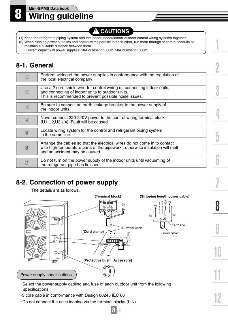
CAUTIONS(1) Keep the refrigerant piping system and the indoor-indoor/indoor-outdoor control wiring systems together.(2) When running power supplies and control wires parallel to each other, run them through separate conduits or
maintain a suitable distance between them.(Current capacity of power supplies: 10A or less for 300m, 50A or less for 500m)
Perform wiring of the power supplies in conformance with the regulation ofthe local electrical company.
Use a 2 core shield wire for control wiring on connecting indoor units,and connecting of indoor units to outdoor units.This is recommended to prevent possible noise issues.
Be sure to connect an earth leakage breaker to the power supply ofthe indoor units.
Never connect 220-240V power to the control wiring terminal block(U1,U2,U3,U4). Fault will be caused.
Locate wiring system for the control and refrigerant piping system in the same line.
Arrange the cables so that the electrical wires do not come in to contact with high-temperature parts of the pipework ; otherwise insulation will meltand an accident may be caused.
Do not turn on the power supply of the indoor units until vacuuming ofthe refrigerant pipe has finished.
8-2. Connection of power supply The details are as follows.
Select the power supply cabling and fuse of each outdoor unit from the followingspecifications:
Do not connect the units looping via the terminal blocks (L,N)
3 core cable in conformance with Design 60245 IEC 66
Power supply specifications
(Terminal block) (Stripping length power cable)
(Cord clamp)
(Protective bush : Accessory)
Power cable
NL
10
L N 10
50 90
Earth line
Power cable

8 -2
8-3. Electrical wiring desin
L N
Over current breakerbreaker (fuse) switch
Earth leakage breaker
Outdoor unit power supply
Earth
Power supplyMCY-MAP###1HT series 1N~ 50Hz 220V-240V
MCY-MAP###1HT2D series 1N~ 60Hz 220V
Outdoor Unit capacities and power supply wire sizes (Reference)
Determine the wire size for the indoor unit according to the number of conncted indoor units downstream.
Observe local regulations in reference to the wire size selection and installtion.
For Indoor Unit power supply(Must be independent from the outdoor unit power supply )
Outdoor unit capacity type Installation fuse
0401 type 6 mm2 Max. 28 m 32A0501 type 6 mm2 Max. 25 m 32A
0601 type 6 mm2 Max. 22 m 40A
25A28A
31A* Design 60245 IEC66
Wir Maximum running currente size *
Outdoorpower source
Indoorpower source
Earth leakage Breakerhand switchOver current breaker (fuse)switch
All models of indoor units
NOTE:The above connecting lengths stated in the table indicate the length from the isolator to the outdoor unit. When thepower supply of the indoor units are connected in parallel, it is assumed that no more than a 2% voltage drop will occur.If the connecting length is to exceed the stated lengths, select a suitable wire in accordance with the local wiring standards.
Model
Item
15A2.0mm2 MAX.20m 3.5mm2 MAX.50m
Field fuseWire size
Power supply wiring
Pull box
Indoor unitIndoor unitIndoor unit
Indoor unitIndoor unitIndoor unit
Single phase50Hz 220-240Vor 60Hz 220VEarth leakage breakerpower switch
(Revised 07 Apr 2006)
8 -3
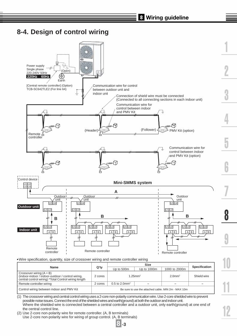
8-4. Design of control wiring
Wire specification, quantity, size of crossover wiring and remote controller wiring
Name Q’tySize
Up to 500m Up to 1000m 1000 to 2000mSpecification
Crossover wiring (A + B)(indoor-indoor / indoor-outdoor / control wiring,central control wiring) *Total Control wiring lengthRemote controller wiring
Control wiring between indoor and PMV Kit
2 cores
2 cores
1.25mm2 2.0mm2 Shield wire
0.5 to 2.0mm2 - - -
Be sure to use the attached cable. MIN 2m - MAX 10m
(1) The crossover wiring and central control wiring uses a 2-core non-polarity communication wire. Use 2-core shielded wire to preventpossible noise issues. Connect the end of the shielded wires and earth(ground) at both the outdoor and indoor unit.Where the shielded wire is connected between a central controller and a outdoor unit, only earth(ground) at one end ofthe central control line.
(2) Use 2-core non-polarity wire for remote controller. (A, B terminals)Use 2-core non-polarity wire for wiring of group control. (A, B terminals)
U3 U4
U1 U2
U1U3
U2U4
U1 U2
A B
U3 U4
U1 U2
U1 U2
A B
U1 U2
A B
U1 U2
A B
U1 U2
A B
Outdoorunit
Outdoorunit
U3 U4
U1 U2
U1 U2
A B
U1 U2
A B
U1 U2
A B
Outdoor
Control device
unit
Remotecontroller Remote controller Remote controller
Mini-SMMS system
A
BB B
Outdoor unit
Indoor unit
PMV Kit (option)(Header) (Follower)Remotecontroller
Communication wire forcontrol between indoorand PMV Kit
Communication wire forcontrol between indoorand PMV Kit (option)
Earth
(Open)
Communication wire for controlbetween outdoor unit andindoor unit
Connection of shield wire must be connected (Connected to all connecting sections in each indoor unit)
[Central remote controller] (Option)TCB-SC642TLE2 (For line 64)
Power supplySingle phase220-240V 50Hz 220Hz 60Hz

8 -4
8-5. Example of system wiring Design In cace of without "PMV Kit"1
Outdoor power supply Outdoor unitMCY-MAP###1HT ser ies : 1N~ 50Hz 220V-240V Indoor unitMCY-MAP###1HT2D series : 1N~ 60Hz 220V Remote controller
Central remote controller (option)Central remote controller power supply Over current breaker (fuse) switch1N~ 50Hz 220-240V Earth leakage breaker1N~ 60Hz 220V Main switch
Pull boxPMV Kit (option)
(Option)L N
U1 U2U3 U4
Outdoor unit
L N U1 U2 U3 U4
Relay connector (At shipment from factory : No connection)
Earth
Earth
(Open)
(Open)
To otherrefrigerant system
Connection of shield wire must be connected
(Connected to all connecting sections in each Indoor u
Control wiring between indoor units
Indoor unit
U1 U2 A B U1 U2 A B U1 U2 A B U1 U2 A B
control
ad L N L N L N
L N
A B A B A B
Remote controller
Group control
Indoor unit
power supply
1N~ 50Hz 220-240V
1N~ 60Hz 220V
Earth Earth
Earth
Earth
nits.)

8 -5
In cace of "PMV Kit"2
Outdoor power supply Outdoor unitMCY-MAP###1HT ser ies : 1N~ 50Hz 220V-240V Indoor unitMCY-MAP###1HT2D series : 1N~ 60Hz 220V Remote controller
Central remote controller (option)Central remote contro lle r power supply Over current breaker (fuse) switch1N~ 50Hz 220-240V Earth leakage breaker1N~ 60Hz 220V Main switch
Pull boxPMV Kit (option)
(Option)L N
U1 U2U3 U4
Outdoor unit
L N U1 U2 U3 U4
Relay connector (At shipment from factory : No connection)
Earth
Earth
(Open)
(Open)
To otherrefrigerant system
Connection of shield wire must be connected
(Connected to all connecting sections in each Indoor units.)
Control wiring between indoor units
Indoor unit
U1 U2 A B U1 U2 A B U1 U2 A B U1 U2 A B
Indoor control
PC boad L N L N L N
L N
A B A B A B
Remote controller
Group control
Indoor unit
power supply
1N~ 50Hz 220-240V
1N~ 60Hz 220V
Earth Earth
Eart
Indoor controlPMV Kit (option)
PC boad
CN82
h
Earth

8 -6
8-6. Electrical characteristics
Outdoor units
Model nameNominal
(V-Ph-Hz)Voltage Range CompressorMin Max RLA kW FLA MCA MOCP ICF
Fan Motor Power Supply
MCY-MAP0401HTMCY-MAP0501HTMCY-MAP0601HT
230-1-50230-1-50230-1-50
198198198
264264264
22.425.327.8
0.063 x 20.063 x 20.063 x 2
1.21.31.3
252831
323240
---
Legend RLA : Rated Load Amps FLA : Full Load Amps kW : Fan Motor Rated Output (kW)
MCA : Minimum Circuit Amps MOCP : Maximum Overcurrent Protection (Amps) ICF : Maximum Instantaneous Current Flow Start
NOTE : RLA is based on the following conditions. Indoor temperature : 27oCDB / 19oCWB Outdoor temperature : 35oCDB
Indoor units50Hz
50Hz
Type Model Nominal Voltage(V-Ph-Hz)
Voltage RangeMin Max
Fan MotorkW FLA
Power SupplyMCA MOCP
MMU-AP 0091 HMMU-AP 0121 HMMU-AP 0151 HMMU-AP 0181 HMMU-AP 0241 HMMU-AP 0271 HMMU-AP 0301 HMMU-AP 0361 HMMU-AP 0481 HMMU-AP 0071 MHMMU-AP 0091 MHMMU-AP 0121 MHMMU-AP 0151 MHMMU-AP 0181 MHMMU-AP 0071 WHMMU-AP 0091 WHMMU-AP 0121 WHMMU-AP 0151 WHMMU-AP 0181 WHMMU-AP 0241 WHMMU-AP 0271 WHMMU-AP 0301 WHMMU-AP 0071 YHMMU-AP 0091 YHMMU-AP 0121 YHMMU-AP 0152 SHMMU-AP 0182 SHMMU-AP 0242 SH
230-1-50230-1-50230-1-50230-1-50230-1-50230-1-50230-1-50230-1-50230-1-50230-1-50230-1-50230-1-50230-1-50230-1-50230-1-50230-1-50230-1-50230-1-50220-1-50230-1-50230-1-50230-1-50230-1-50230-1-50230-1-50230-1-50230-1-50230-1-50
198198198198198198198198198198198198198198198198198198198198198198198198198198198198
264264264264264264264264264264264264264264264264264264264264264264264264264264264264
0.0600.0600.0600.0600.0600.0600.0600.0900.0900.0600.0600.0600.0600.0600.0530.0530.0530.0390.0390.0530.0530.0530.0220.0220.0220.0300.0300.030
0.200.200.220.240.280.280.400.680.930.320.350.360.480.480.360.360.360.370.370.530.530.540.280.280.280.400.420.71
0.250.250.280.300.350.350.500.851.160.400.440.450.600.600.450.450.450.460.460.660.660.680.350.350.350.490.530.88
15151515151515151515151515151515151515151515151515151515
4-way AirDischargeCassette Type
Compact4-way Cassette(600 x 600) Type
2-way AirDischargeCassette Type
1-way AirDischargeCassette Type

8 -7
Indoor units50Hz
Type Model Nominal Voltage(V-Ph-Hz)
Voltage RangeMin Max
Fan MotorkW FLA
Power SupplyMCA MOCP
MMD-AP 0071 BHMMD-AP 0091 BHMMD-AP 0121 BHMMD-AP 0151 BHMMD-AP 0181 BHMMD-AP 0241 BHMMD-AP 0271 BHMMD-AP 0301 BHMMD-AP 0361 BHMMD-AP 0481 BHMMD-AP 0071 SPHMMD-AP 0091 SPHMMD-AP 0121 SPHMMD-AP 0151 SPHMMD-AP 0181 SPHMMD-AP 0181 HMMD-AP 0241 HMMD-AP 0271 HMMD-AP 0361 HMMD-AP 0481 HMMC-AP 0151 HMMC-AP 0181 HMMC-AP 0241 HMMC-AP 0271 HMMC-AP 0361 HMMC-AP 0481 HMMK-AP 0071 HMMK-AP 0091 HMMK-AP 0121 HMMK-AP 0151 HMMK-AP 0181 HMMK-AP 0241 HMMK-AP 0072 HMMK-AP 0092 HMMK-AP 0122 HMML-AP 0071 HMML-AP 0091 HMML-AP 0121 HMML-AP 0151 HMML-AP 0181 HMML-AP 0241 HMML-AP 0071 BHMML-AP 0091 BHMML-AP 0121 BHMML-AP 0151 BHMML-AP 0181 BHMML-AP 0241 BHMMF-AP 0151 HMMF-AP 0181 HMMF-AP 0241 HMMF-AP 0271 HMMF-AP 0361 HMMF-AP 0481 H
230-1-50230-1-50230-1-50230-1-50230-1-50230-1-50230-1-50230-1-50230-1-50230-1-50230-1-50230-1-50230-1-50230-1-50230-1-50230-1-50230-1-50230-1-50230-1-50230-1-50230-1-50220-1-50230-1-50230-1-50230-1-50230-1-50230-1-50230-1-50230-1-50230-1-50230-1-50230-1-50230-1-50230-1-50230-1-50230-1-50230-1-50230-1-50230-1-50230-1-50230-1-50230-1-50230-1-50230-1-50230-1-50230-1-50230-1-50230-1-50230-1-50230-1-50230-1-50230-1-50230-1-50
198198198198198198198198198198198198198198198198198198198198198198198198198198198198198198198198198198198198198198198198198198198198198198198198198198198198198
264264264264264264264264264264264264264264264264264264264264264264264264264264264264264264264264264264264264264264264264264264264264264264264264264264264264264
0.1200.1200.1200.1200.1200.1200.1200.1200.1200.1200.0600.0600.0600.0600.0600.1600.1600.1600.2600.2600.0300.0300.0400.0400.0800.0800.0300.0300.0300.0300.0300.0300.0300.0300.0300.0450.0450.0450.0450.0700.0700.0190.0190.0190.0700.0700.0700.0370.0370.0630.0630.1100.160
0.330.330.390.390.500.600.600.700.961.130.350.350.370.380.470.931.551.551.872.120.330.370.480.480.900.960.350.350.350.370.370.400.200.210.220.300.300.490.490.540.540.290.290.290.520.520.530.770.771.011.011.481.84
0.410.410.490.490.620.750.750.881.201.410.440.440.470.480.591.161.941.942.342.650.410.460.600.601.131.200.440.440.440.460.460.500.240.260.270.370.370.620.620.680.680.360.360.360.650.650.660.960.961.271.271.852.30
1515151515151515151515151515151515151515151515151515151515151515151515151515151515151515151515151515151515
Concealed DuctType
Concealed DuctHigh StaticPressure Type
Under Ceiling Type
Floor StandingConcealed Type
Floor StandingType
High Wall 1seriesType
Floor StandingCabinet Type
Slim Duct Type
High Wall 2seriesType

8 -8
Indoor units60Hz
Type Model Nominal Voltage(V-Ph-Hz)
Voltage RangeMin Max
Fan MotorkW FLA
Power SupplyMCA MOCP
MMU-AP 0091 HMMU-AP 0121 HMMU-AP 0151 HMMU-AP 0181 HMMU-AP 0241 HMMU-AP 0271 HMMU-AP 0301 HMMU-AP 0361 HMMU-AP 0481 HMMU-AP 0071 MHMMU-AP 0091 MHMMU-AP 0121 MHMMU-AP 0151 MHMMU-AP 0181 MHMMU-AP 0071 WHMMU-AP 0091 WHMMU-AP 0121 WHMMU-AP 0151 WHMMU-AP 0181 WHMMU-AP 0241 WHMMU-AP 0271 WHMMU-AP 0301 WHMMU-AP 0071 YHMMU-AP 0091 YHMMU-AP 0121 YHMMU-AP 0152 SHMMU-AP 0182 SHMMU-AP 0242 SH
220-1-60220-1-60220-1-60220-1-60220-1-60220-1-60220-1-60220-1-60220-1-60220-1-60220-1-60220-1-60220-1-60220-1-60220-1-60220-1-60220-1-60220-1-60220-1-60220-1-60220-1-60220-1-60220-1-60220-1-60220-1-60220-1-60220-1-60220-1-60
198198198198198198198198198198198198198198198198198198198198198198198198198198198198
242242242242242242242242242242242242242242242242242242242242242242242242242242242242
0.0600.0600.0600.0600.0600.0600.0600.0900.0900.0600.0600.0600.0600.0600.0530.0530.0530.0390.0390.0530.0530.0530.0220.0220.0220.0300.0300.030
0.210.210.230.250.290.290.420.700.980.310.330.350.470.470.380.380.380.440.440.610.610.670.300.300.300.400.450.75
0.260.260.290.310.370.370.520.881.220.390.410.440.590.590.470.470.470.550.550.760.760.840.370.370.370.500.570.94
15151515151515151515151515151515151515151515151515151515
4-way AirDischargeCassette Type
Compact4-way Cassette(600 x 600) Type
2-way AirDischargeCassette Type
1-way AirDischargeCassette Type
8-6. Electrical characteristics
Outdoor units
Model nameNominal
(V-Ph-Hz)Voltage Range CompressorMin Max RLA kW FLA MCA MOCP ICF
Fan Motor Power Supply
MCY-MAP0401HT2DMCY-MAP0501HT2DMCY-MAP0601HT2D
220-1-60220-1-60220-1-60
198198198
242242242
22.425.327.8
0.063 x 20.063 x 20.063 x 2
1.21.31.3
252831
323240
---
Legend RLA : Rated Load Amps FLA : Full Load Amps kW : Fan Motor Rated Output (kW)
MCA : Minimum Circuit Amps MOCP : Maximum Overcurrent Protection (Amps) ICF : Maximum Instantaneous Current Flow Start
NOTE : RLA is based on the following conditions. Indoor temperature : 27oCDB / 19oCWB Outdoor temperature : 35oCDB
60Hz

8 -9
Indoor units 60Hz
Type Model Nominal Voltage(V-Ph-Hz)
Voltage RangeMin Max
Fan MotorkW FLA
Power SupplyMCA MOCP
MMD-AP 0071 BHMMD-AP 0091 BHMMD-AP 0121 BHMMD-AP 0151 BHMMD-AP 0181 BHMMD-AP 0241 BHMMD-AP 0271 BHMMD-AP 0301 BHMMD-AP 0361 BHMMD-AP 0481 BHMMD-AP 0071 SPHMMD-AP 0091 SPHMMD-AP 0121 SPHMMD-AP 0151 SPHMMD-AP 0181 SPHMMD-AP 0181 HMMD-AP 0241 HMMD-AP 0271 HMMD-AP 0361 HMMD-AP 0481 HMMC-AP 0151 HMMC-AP 0181 HMMC-AP 0241 HMMC-AP 0271 HMMC-AP 0361 HMMC-AP 0481 HMMK-AP 0071 HMMK-AP 0091 HMMK-AP 0121 HMMK-AP 0151 HMMK-AP 0181 HMMK-AP 0241 HMMK-AP 0072 HMMK-AP 0092 HMMK-AP 0122 HMML-AP 0071 HMML-AP 0091 HMML-AP 0121 HMML-AP 0151 HMML-AP 0181 HMML-AP 0241 HMML-AP 0071 BHMML-AP 0091 BHMML-AP 0121 BHMML-AP 0151 BHMML-AP 0181 BHMML-AP 0241 BHMMF-AP 0151 HMMF-AP 0181 HMMF-AP 0241 HMMF-AP 0271 HMMF-AP 0361 HMMF-AP 0481 H
220-1-60220-1-60220-1-60220-1-60220-1-60220-1-60220-1-60220-1-60220-1-60220-1-60220-1-60220-1-60220-1-60220-1-60220-1-60220-1-60220-1-60220-1-60220-1-60220-1-60220-1-60220-1-60220-1-60220-1-60220-1-60220-1-60220-1-60220-1-60220-1-60220-1-60220-1-60220-1-60220-1-60220-1-60220-1-60220-1-60220-1-60220-1-60220-1-60220-1-60220-1-60220-1-60220-1-60220-1-60220-1-60220-1-60220-1-60220-1-60220-1-60220-1-60220-1-60220-1-60220-1-60
198198198198198198198198198198198198198198198198198198198198198198198198198198198198198198198198198198198198198198198198198198198198198198198198198198198198198
242242242242242242242242242242242242242242242242242242242242242242242242242242242242242242242242242242242242242242242242242242242242242242242242242242242242242
0.1200.1200.1200.1200.1200.1200.1200.1200.1200.1200.0600.0600.0600.0600.0600.1600.1600.1600.2600.2600.0300.0300.0400.0400.0800.0800.0300.0300.0300.0300.0300.0300.0300.0300.0300.0450.0450.0450.0450.0700.0700.0190.0190.0190.0700.0700.0700.0370.0370.0630.0630.1100.160
0.350.350.410.410.520.630.630.731.001.180.320.320.360.370.441.062.072.072.382.600.350.390.500.500.941.000.370.370.370.390.390.400.210.220.230.290.290.510.510.610.610.310.310.310.530.530.590.770.771.041.041.582.01
0.430.430.510.510.650.780.780.911.251.480.410.410.450.470.561.322.592.592.983.250.430.480.630.631.181.250.460.460.460.480.480.500.260.270.290.360.360.630.630.760.760.390.390.390.660.660.730.960.961.291.291.972.52
1515151515151515151515151515151515151515151515151515151515151515151515151515151515151515151515151515151515
Concealed DuctType
Concealed DuctHigh StaticPressure Type
Under Ceiling Type
Floor StandingConcealed Type
Floor StandingType
High Wall 1seriesType
Floor StandingCabinet Type
Slim Duct Type
High Wall 2seriesType


9-1 -1
9-1-1. Specifications
Note 1 : The cooling capacities and electrical characteristics are measured under the conditions specified by JIS B 8615 based on thereference piping. The reference piping consists of 5 m of main piping and 2.5 m of branch piping connected with 0 meter height.
Note 2 : The sound level are measured in an anechoic chamber in accordance with JIS B8616. Normally, the values measured in theactual operating environment become larger than the indicated values due to the effects of external sound.
Note : Rated conditions Cooling : Indoor air temperature 27oC DB/19oC WB, Outdoor air temperature 35oC DBHeating : Indoor air temperature 20oC DB, Outdoor air temperature 7oC DB/6oC WB
50Hz
Model name MMU-
Cooling/Heating capacity (Note 1) (kW)
Electricalcharacteris-t ics
Power supply
Running current (A)
Power consumption (kW)
Starting current (A)
Appearance
Main unit
Ceilingpanel
Model
Panel color
Outerdimension
Main unit
Ceilingpanel
Height (mm)
Width (mm)
Depth (mm)
Height (mm)
Width (mm)
Depth (mm)
Total weighMain unit (kg)
Ceiling panel (kg)
Heat exchanger
Soundproof/Heat-insulatingmaterial
Fan unit
Fan
Standard air flow(High/Mid/Low)
(m3/h)
Motor (W)
Air filter
Controller
Connectingpipe
Gas side (mm)
Liquid side (mm)
Drain port (Nominal dia. mm)
Sound pressure level (Note 2)(High/Mid/Low) (dB(A))
AP0091H
2.8/3.2
AP0121H
3.6/4.0
AP0151H
4.5/5.0
AP0181H
5.6/6.3
AP0241H
7.1/8.0
AP0271H
8.0/9.0
AP0301H
9.0/10.0
AP0361H
11.2/12.5
AP0481H
14.0/16.0
1 phase 50Hz 230V (220-240V) (Separate power supply for indoor units is required.)
0.17
0.020
0.30
0.19
0.022
0.33
0.21
0.026
0.36
0.24
0.032
0.42
0.35
0.048
0.59
0.59
0.070
0.87
0.81
0.110
1.23
Heat-insulating material attached Zinc hot dipping steel plate
RBC-U21PG (W)-E
Moon white (Munsell/2.5GY 9.0/0.5)
256 319
840
840
35
950
950
20 22 23 28
4.5
Non-flammable insulation
Finned tube
Turbo fan
800(730/680)
930(830/790)
1,050(920/800)
1,200(920/820)
1,320(1,110/850)
1,680(1,300/1,070)
2,040(1,430/1,130)
60 90
Standard filter (Long life filter)
Remote controller
O/ 9.5 O/ 12.7 O/ 15.9
O/ 6.4
25 (Polyvinyl chloride tube)
30/29/27 31/29/27 32/29/28 34/31/28 37/33/30 40/36/33 44/38/34
O/ 9.5
PMV Kit Not available
Specifications (50Hz)

9-1 -2
60Hz
Model name MMU-
(kW)Cooling/Heating capacity (Note 1)
AP0091H
2.8/3.2
Power supply
Electricalcharacteristics
Running current
Power consumption
Starting current
Main unit
Ceilingpanel
Model
Panel color
Height
Width
Depth
Height
Width
Depth
Main unit
Ceilingpanel
Outerdimension
Total weightMain unit
Ceiling panel
Heat exchanger
Soundproof/Heat-insulatingmaterial
Fan
Motor
Fan unit Standard air flow(High/Mid./Low)
Air filter
Controller
Gas side
Liquid side
Drain port
Connectingpipe
Sound pressure level (Note 2)(High/Mid./Low)
(A)
(kW)
(A)
(mm)
(mm)
(mm)
(mm)
(mm)
(mm)
(kg)
(kg)
(m3/h)
(W)
(mm)
(mm)
(Nominal dia. mm)
(dB(A))
AP0121H
3.6/4.0
AP0151H
4.5/5.0
AP0181H
5.6/6.3
AP0241H
7.1/8.0
AP0271H
8.0/9.0
AP0301H
9.0/10.0
AP0361H
11.2/12.5 14.0/16.0
1 phase 60Hz 220V (Separate power supply for indoor units is required.)
0.18 0.20 0.22 0.26 0.37 0.61 0.85
0.020 0.022 0.026 0.032 0.048 0.070 0.110
0.30 0.33 0.36 0.42 0.59 0.87 1.23
Heat-insulating material attached Zinc hot dipping steel plate
RBC-U21PG (W) -E
Moon white (Munsell/2.5GY 9.0/0.5)
256 319
840
840
35
950
950
20 22 23 28
4.5
Finned tube
Non-flammable insulation
Turbo fan
800(730/680)
930(830/790)
1,050(920/800)
1,200(920/820)
1,320(1,110/850)
1,680(1,300/1,070)
2,040(1,430/1,130)
60 90
Standard filter (Long life filter)
O/ 9.5 O/ 12.7 O/ 15.9
O/ 6.4 O/ 9.5
25 (Polyvinyl chloride tube)
30/29/27 31/29/27 32/29/28 34/31/28 37/33/30 40/36/33 44/38/34
Appearance
Remote controller
Note 1 : The cooling capacities and electrical characteristics are measured under the conditions specified by JIS B 8615 based on thereference piping. The reference piping consists of 5 m of main piping and 2.5 m of branch piping connected with 0 meter height.
Note 2 : The sound levels are measured in an anechoic chamber in accordance with JIS B8616. Normally, the values measured inthe actual operating environment become larger than the indicated values due to the effects of external sound.
Note : Rated conditions Cooling : Indoor air temperature 27OC DB/19OC WB, Outdoor air temperature 35OC DBHeating : Indoor air temperature 20OC DB, Outdoor air temperature 7OC DB/6OC WB
AP0481H
PMV Kit Not available
Specifications (60Hz)

9-1 -3
(NOTE)As ABS is used for the drain dischargeport of the main unit, the vinyl chloridepaste cannot be used.Use the flexible hose (Band fix)included in the package.
200
200
Check port( 450)
Check port( 450)
Electric parts box
Z35
o
105
105
B97
16120
4 2.7
120
57188
64
57.525360
415
381.6
840 840
30
1000 or more
1000
or
mor
e15
or
mor
e
15 o
r m
ore
1000 or more
250 70270
35 210
45 113
174
130
A
88
227480
346.
5
254.
5 950
pane
l ext
erna
l dim
ensi
on
790
hang
ing
bolt
pitc
h
723 hanging bolt pitch
950panel external dimension
Suction grille (Air suction port)
Air discharge port (4-way)
860 to 910ceiling open dimension
860
to 9
10ce
iling
ope
n di
men
sion
Hanging boltM10 or W3/8 local arrange
Bottom face of ceiling Bottom face of ceiling
For branch duct knockout square hole O/ 150(2 positions at right side)
Refrigerant pipe connecting port(Gas)Refrigerant pipe connecting port(Liquid)
Drain discharge port
Model A B256319
120183
AP0091H to AP0301HAP0361H to AP0481H
mm
Indoor unit Bottom face of ceiling
Bottom face of ceiling
Knockout for flesh air intakeFor O/ 100
Sta
nd-u
p85
0 or
less
Sta
nd-u
p64
0 or
less
Z view Drain-up standing-up size Space required for installation and servicing
Note: All dimensions are in mm.
Wired remote controller RBC-AMT31E
Simple wired remote controller RBC-AS21E2
Wireless remote controller kit TCB-AX21U(W)-E2
Weekly timer application RBC-AMT31E and RBC-EXW21E2
9-1-2. Dimension
MMU-AP0091H to P0481H
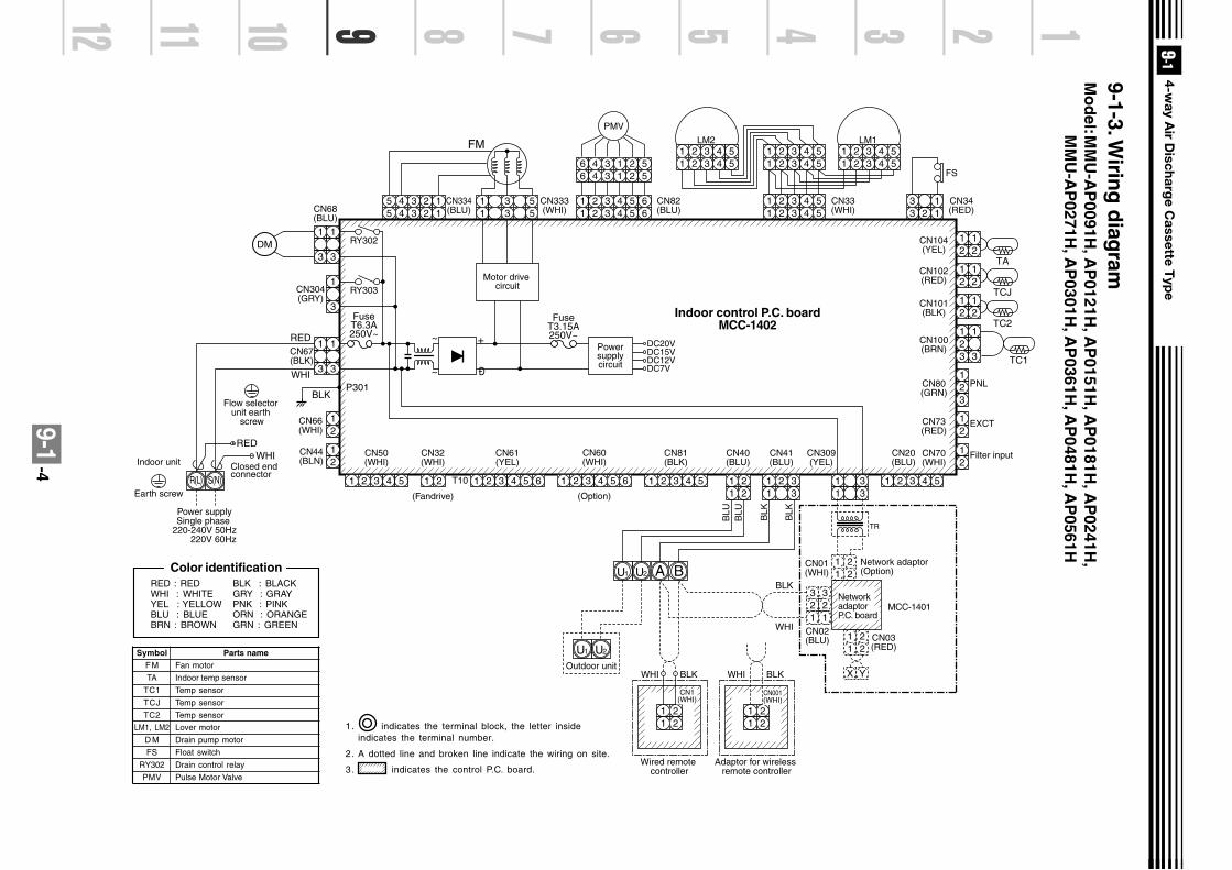
9-1-4
CN104(YEL)
CN102(RED)
CN101(BLK)
1 2 3 4 51 2 3 4 5
1 2 3 4 51 2 3 4 5
1 2 3 4 51 2 3 4 5
1 2 3 4 5 61 2 3 4 5
1 2 3 4 51 2 3 4 5 6
6 4 3 1 2 56 4 3 1 2 5
3 13 2 1
CN34(RED)
FS
CN33(WHI)
CN82(BLU)
5 4 3 2 15 4 3 2 1
CN334(BLU)
DC20V
CN333(WHI)CN68
(BLU)
CN304(GRY)
CN66(WHI)
CN44(BLN)
CN67(BLK)
LM1
PMV
12
12
TA12
12
TCJ12
12
TC2
CN100(BRN)
12
12
33
CN80(GRN)
PNL
EXCT
12
CN73(RED)
12
Filter input
(Option)(Fandrive)
CN70(WHI)
CN20(BLU)
12
3
TC1
1 2 3 4 51 2 3 4 5
LM2
1 2 3 4 5
CN81(BLK)
CN60(WHI)
CN32(WHI)
CN61(YEL)
CN50(WHI)
CN40(BLU)
T10 1 2 3 4 51 21 2 3 4 5 61 2 3 4 51 2 3
CN309(YEL)
1 2 31 2 3
1 21 2
CN41(BLU)
1 2 31 2 3
4 5 6
RY302
RY303
123
123
123
123
12
12
12
3
~ +
~ Ð
FuseT6.3A250V~
FuseT3.15A250V~
DC15VDC12VDC7V
P301BLK
RED
WHI
WHIRED
S(N)R(L)
Power supplySingle phase
220-240V 50Hz 220V 60Hz
Indoor unit
Earth screw
DM
FM
Powersupplycircuit
Motor drive circuit
Closed end connector
CN01(WHI)
CN02(BLU)
Adaptor for wireless remote controller
CN03(RED)
Network adaptor (Option)
1 21 2
1 21 2
1 21 2
X Y
3 32 21 1
Wired remote controller
1 2
BAU2
1 2
CN1(WHI)
CN001(WHI)
WHIOutdoor unit
BLK WHI BLK
BLK
BLU
BLU
BLK
BLK
TR
WHI
U1
U2U1
Network adaptorP.C. board
MCC-1401
Flow selector unit earth
screw
Color identificationRED : REDWHI : WHITEYEL : YELLOWBLU : BLUEBRN : BROWN
BLK : BLACKGRY : GRAYPNK : PINKORN : ORANGEGRN : GREEN
SymbolFM
TA
TC1
TCJ
TC2
LM1, LM2
D M
FS
RY302
PMV
Parts nameFan motor
Indoor temp sensor
Temp sensor
Temp sensor
Temp sensor
Lover motor
Drain pump motor
Float switch
Drain control relay
Pulse Motor Valve
Indoor control P.C. boardMCC-1402
1. indicates the terminal block, the letter insideindicates the terminal number.
2. A dotted line and broken line indicate the wiring on site.
3. indicates the control P.C. board.
9-1-3. Wirin
g d
iagram
Mo
del:M
MU
-AP
0091H, A
P0121H
, AP
0151H, A
P0181H
, AP
0241H,
MM
U-A
P0271H
, AP
0301H, A
P0361H
, AP
0481H, A
P0561H

9-1 -5
TC : Total Capacity (kW) SHC : Sensible Heat Capacity (kW)Indoor air temp.
Unit Outdoor 16.0˚CWB 18.0˚CWB 19.0˚CWB 20.0˚CWB 22.0˚CWB 24.0˚CWBsize air temp. 23˚CDB 26˚CDB 27˚CDB 28˚CDB 30˚CDB 32˚CDB
˚CDB TC SHC TC SHC TC SHC TC SHC TC SHC TC SHC10.0 2.5 2.0 2.7 2.1 2.8 2.1 2.9 2.1 3.1 2.1 3.2 2.012.0 2.5 2.0 2.7 2.1 2.8 2.1 2.9 2.1 3.1 2.1 3.2 2.014.0 2.5 2.0 2.7 2.1 2.8 2.1 2.9 2.1 3.1 2.1 3.2 2.016.0 2.5 2.0 2.7 2.1 2.8 2.1 2.9 2.1 3.1 2.1 3.2 2.018.0 2.5 2.0 2.7 2.1 2.8 2.1 2.9 2.1 3.1 2.1 3.2 2.020.0 2.5 2.0 2.7 2.1 2.8 2.1 2.9 2.1 3.1 2.1 3.2 2.021.0 2.5 2.0 2.7 2.1 2.8 2.1 2.9 2.1 3.1 2.1 3.2 2.0
009 23.0 2.5 2.0 2.7 2.1 2.8 2.1 2.9 2.1 3.1 2.1 3.2 2.025.0 2.5 2.0 2.7 2.1 2.8 2.1 2.9 2.1 3.1 2.1 3.2 2.027.0 2.5 2.0 2.7 2.1 2.8 2.1 2.9 2.1 3.1 2.1 3.2 2.029.0 2.5 2.0 2.7 2.1 2.8 2.1 2.9 2.1 3.1 2.1 3.2 2.031.0 2.5 2.0 2.7 2.1 2.8 2.1 2.9 2.1 3.1 2.1 3.2 2.033.0 2.5 2.0 2.7 2.1 2.8 2.1 2.9 2.1 3.1 2.1 3.2 2.035.0 2.5 2.0 2.7 2.1 2.8 2.1 2.9 2.1 3.1 2.1 3.2 2.037.0 2.5 1.9 2.7 2.1 2.7 2.1 2.8 2.1 3.0 2.0 3.1 2.039.0 2.4 1.9 2.6 2.0 2.7 2.0 2.8 2.0 2.9 2.0 3.1 1.910.0 3.3 2.5 3.5 2.6 3.6 2.6 3.7 2.6 3.9 2.6 4.1 2.512.0 3.3 2.5 3.5 2.6 3.6 2.6 3.7 2.6 3.9 2.6 4.1 2.514.0 3.3 2.5 3.5 2.6 3.6 2.6 3.7 2.6 3.9 2.6 4.1 2.516.0 3.3 2.5 3.5 2.6 3.6 2.6 3.7 2.6 3.9 2.6 4.1 2.518.0 3.3 2.5 3.5 2.6 3.6 2.6 3.7 2.6 3.9 2.6 4.1 2.520.0 3.3 2.5 3.5 2.6 3.6 2.6 3.7 2.6 3.9 2.6 4.1 2.521.0 3.3 2.5 3.5 2.6 3.6 2.6 3.7 2.6 3.9 2.6 4.1 2.5
012 23.0 3.3 2.5 3.5 2.6 3.6 2.6 3.7 2.6 3.9 2.6 4.1 2.525.0 3.3 2.5 3.5 2.6 3.6 2.6 3.7 2.6 3.9 2.6 4.1 2.527.0 3.3 2.5 3.5 2.6 3.6 2.6 3.7 2.6 3.9 2.6 4.1 2.529.0 3.3 2.5 3.5 2.6 3.6 2.6 3.7 2.6 3.9 2.6 4.1 2.531.0 3.3 2.5 3.5 2.6 3.6 2.6 3.7 2.6 3.9 2.6 4.1 2.533.0 3.3 2.5 3.5 2.6 3.6 2.6 3.7 2.6 3.9 2.6 4.1 2.535.0 3.3 2.5 3.5 2.6 3.6 2.6 3.7 2.6 3.9 2.6 4.1 2.537.0 3.2 2.4 3.4 2.6 3.5 2.5 3.6 2.5 3.8 2.5 4.0 2.539.0 3.1 2.3 3.4 2.5 3.5 2.4 3.6 2.4 3.8 2.4 3.9 2.410.0 4.1 3.0 4.4 3.2 4.5 3.2 4.6 3.2 4.9 3.2 5.1 3.112.0 4.1 3.0 4.4 3.2 4.5 3.2 4.6 3.2 4.9 3.2 5.1 3.114.0 4.1 3.0 4.4 3.2 4.5 3.2 4.6 3.2 4.9 3.2 5.1 3.116.0 4.1 3.0 4.4 3.2 4.5 3.2 4.6 3.2 4.9 3.2 5.1 3.118.0 4.1 3.0 4.4 3.2 4.5 3.2 4.6 3.2 4.9 3.2 5.1 3.120.0 4.1 3.0 4.4 3.2 4.5 3.2 4.6 3.2 4.9 3.2 5.1 3.121.0 4.1 3.0 4.4 3.2 4.5 3.2 4.6 3.2 4.9 3.2 5.1 3.1
015 23.0 4.1 3.0 4.4 3.2 4.5 3.2 4.6 3.2 4.9 3.2 5.1 3.125.0 4.1 3.0 4.4 3.2 4.5 3.2 4.6 3.2 4.9 3.2 5.1 3.127.0 4.1 3.0 4.4 3.2 4.5 3.2 4.6 3.2 4.9 3.2 5.1 3.129.0 4.1 3.0 4.4 3.2 4.5 3.2 4.6 3.2 4.9 3.2 5.1 3.131.0 4.1 3.0 4.4 3.2 4.5 3.2 4.6 3.2 4.9 3.2 5.1 3.133.0 4.1 3.0 4.4 3.2 4.5 3.2 4.6 3.2 4.9 3.2 5.1 3.135.0 4.1 3.0 4.4 3.2 4.5 3.2 4.6 3.2 4.9 3.2 5.1 3.137.0 4.0 3.0 4.3 3.1 4.4 3.1 4.5 3.1 4.8 3.1 5.0 3.039.0 3.9 2.8 4.2 3.0 4.3 3.0 4.4 3.0 4.7 3.0 4.9 2.9
9-1-4. Sensible capacity table(MMU-AP***H)
Cooling capacity
(Revised 12 July 2006)

9-1 -6
Indoor air temp.Unit Outdoor 16.0˚CWB 18.0˚CWB 19.0˚CWB 20.0˚CWB 22.0˚CWB 24.0˚CWBsize air temp. 23˚CDB 26˚CDB 27˚CDB 28˚CDB 30˚CDB 32˚CDB
˚CDB TC SHC TC SHC TC SHC TC SHC TC SHC TC SHC10.0 5.1 3.8 5.4 4.0 5.6 4.0 5.8 4.0 6.1 4.0 6.4 3.912.0 5.1 3.8 5.4 4.0 5.6 4.0 5.8 4.0 6.1 4.0 6.4 3.914.0 5.1 3.8 5.4 4.0 5.6 4.0 5.8 4.0 6.1 4.0 6.4 3.916.0 5.1 3.8 5.4 4.0 5.6 3.9 5.8 4.0 6.1 4.0 6.4 3.918.0 5.1 3.8 5.4 4.0 5.6 4.0 5.8 4.0 6.1 4.0 6.4 3.920.0 5.1 3.8 5.4 4.0 5.6 4.0 5.8 4.0 6.1 4.0 6.4 3.921.0 5.1 3.8 5.4 4.0 5.6 4.0 5.8 4.0 6.1 4.0 6.4 3.9
018 23.0 5.1 3.8 5.4 4.0 5.6 4.0 5.8 4.0 6.1 4.0 6.4 3.925.0 5.1 3.8 5.4 4.0 5.6 4.0 5.8 4.0 6.1 4.0 6.4 3.927.0 5.1 3.8 5.4 4.0 5.6 4.0 5.8 4.0 6.1 4.0 6.4 3.929.0 5.1 3.8 5.4 4.0 5.6 4.0 5.8 4.0 6.1 4.0 6.4 3.931.0 5.1 3.8 5.4 4.0 5.6 4.0 5.8 4.0 6.1 4.0 6.4 3.933.0 5.1 3.8 5.4 4.0 5.6 4.0 5.8 4.0 6.1 4.0 6.4 3.935.0 5.1 3.8 5.4 4.0 5.6 4.0 5.8 4.0 6.1 4.0 6.4 3.937.0 5.0 3.7 5.3 3.9 5.5 3.9 5.7 3.9 6.0 3.9 6.3 3.839.0 4.9 3.6 5.2 3.8 5.4 3.8 5.5 3.8 5.9 3.7 6.1 3.610.0 6.4 4.6 6.9 4.9 7.1 4.9 7.3 4.9 7.7 4.9 8.1 4.712.0 6.4 4.6 6.9 4.9 7.1 4.9 7.3 4.9 7.7 4.9 8.1 4.714.0 6.4 4.6 6.9 4.9 7.1 4.9 7.3 4.9 7.7 4.9 8.1 4.716.0 6.4 4.6 6.9 4.9 7.1 4.9 7.3 4.9 7.7 4.9 8.1 4.718.0 6.4 4.6 6.9 4.9 7.1 4.9 7.3 4.9 7.7 4.9 8.1 4.720.0 6.4 4.6 6.9 4.9 7.1 4.9 7.3 4.9 7.7 4.9 8.1 4.721.0 6.4 4.6 6.9 4.9 7.1 4.9 7.3 4.9 7.7 4.9 8.1 4.7
024 23.0 6.4 4.6 6.9 4.9 7.1 4.9 7.3 4.9 7.7 4.9 8.1 4.725.0 6.4 4.6 6.9 4.9 7.1 4.9 7.3 4.9 7.7 4.9 8.1 4.727.0 6.4 4.6 6.9 4.9 7.1 4.9 7.3 4.9 7.7 4.9 8.1 4.729.0 6.4 4.6 6.9 4.9 7.1 4.9 7.3 4.9 7.7 4.9 8.1 4.731.0 6.4 4.6 6.9 4.9 7.1 4.9 7.3 4.9 7.7 4.9 8.1 4.733.0 6.4 4.6 6.9 4.9 7.1 4.9 7.3 4.9 7.7 4.9 8.1 4.735.0 6.4 4.6 6.9 4.9 7.1 4.9 7.3 4.9 7.7 4.9 8.1 4.737.0 6.3 4.5 6.7 4.8 7.0 4.8 7.2 4.8 7.6 4.8 7.9 4.639.0 6.2 4.4 6.6 4.6 6.8 4.6 7.0 4.6 7.4 4.6 7.8 4.510.0 7.3 5.2 7.8 5.5 8.0 5.5 8.2 5.5 8.7 5.4 9.1 5.312.0 7.3 5.2 7.8 5.5 8.0 5.5 8.2 5.5 8.7 5.4 9.1 5.314.0 7.3 5.2 7.8 5.5 8.0 5.5 8.2 5.5 8.7 5.4 9.1 5.316.0 7.3 5.2 7.8 5.5 8.0 5.5 8.2 5.5 8.7 5.4 9.1 5.318.0 7.3 5.2 7.8 5.5 8.0 5.5 8.2 5.5 8.7 5.4 9.1 5.320.0 7.3 5.2 7.8 5.5 8.0 5.5 8.2 5.5 8.7 5.4 9.1 5.321.0 7.3 5.2 7.8 5.5 8.0 5.5 8.2 5.5 8.7 5.4 9.1 5.3
027 23.0 7.3 5.2 7.8 5.5 8.0 5.5 8.2 5.5 8.7 5.4 9.1 5.325.0 7.3 5.2 7.8 5.5 8.0 5.5 8.2 5.5 8.7 5.4 9.1 5.327.0 7.3 5.2 7.8 5.5 8.0 5.5 8.2 5.5 8.7 5.4 9.1 5.329.0 7.3 5.2 7.8 5.5 8.0 5.5 8.2 5.5 8.7 5.4 9.1 5.331.0 7.3 5.2 7.8 5.5 8.0 5.5 8.2 5.5 8.7 5.4 9.1 5.333.0 7.3 5.2 7.8 5.5 8.0 5.5 8.2 5.5 8.7 5.4 9.1 5.335.0 7.3 5.2 7.8 5.5 8.0 5.5 8.2 5.5 8.7 5.4 9.1 5.337.0 7.1 5.1 7.6 5.4 7.8 5.4 8.1 5.4 8.5 5.3 8.9 5.239.0 7.0 4.9 7.4 5.2 7.7 5.2 7.9 5.2 8.4 5.1 8.8 5.0
Cooling capacity (cont.)
(Revised 12 July 2006)

9-1 -7
Indoor air temp.Unit Outdoor 16.0°CWB 18.0°CWB 19.0°CWB 20.0°CWB 22.0°CWB 24.0°CWBsize air temp. 23°CDB 26°CDB 27°CDB 28°CDB 30°CDB 32°CDB
°CDB TC SHC TC SHC TC SHC TC SHC TC SHC TC SHC10.0 8.2 5.9 8.7 6.2 9.0 6.2 9.3 6.2 9.8 6.1 10.3 6.012.0 8.2 5.9 8.7 6.2 9.0 6.2 9.3 6.2 9.8 6.1 10.3 6.014.0 8.2 5.9 8.7 6.2 9.0 6.2 9.3 6.2 9.8 6.1 10.3 6.016.0 8.2 5.9 8.7 6.2 9.0 6.2 9.3 6.2 9.8 6.1 10.3 6.018.0 8.2 5.9 8.7 6.2 9.0 6.2 9.3 6.2 9.8 6.1 10.3 6.020.0 8.2 5.9 8.7 6.2 9.0 6.2 9.3 6.2 9.8 6.1 10.3 6.021.0 8.2 5.9 8.7 6.2 9.0 6.2 9.3 6.2 9.8 6.1 10.3 6.0
030 23.0 8.2 5.9 8.7 6.2 9.0 6.2 9.3 6.2 9.8 6.1 10.3 6.025.0 8.2 5.9 8.7 6.2 9.0 6.2 9.3 6.2 9.8 6.1 10.3 6.027.0 8.2 5.9 8.7 6.2 9.0 6.2 9.3 6.2 9.8 6.1 10.3 6.029.0 8.2 5.9 8.7 6.2 9.0 6.2 9.3 6.2 9.8 6.1 10.3 6.031.0 8.2 5.9 8.7 6.2 9.0 6.2 9.3 6.2 9.8 6.1 10.3 6.033.0 8.2 5.9 8.7 6.2 9.0 6.2 9.3 6.2 9.8 6.1 10.3 6.035.0 8.2 5.9 8.7 6.2 9.0 6.2 9.3 6.2 9.8 6.1 10.3 6.037.0 8.0 5.7 8.6 6.1 8.8 6.1 9.1 6.1 9.6 6.0 10.1 5.939.0 7.8 5.5 8.4 5.9 8.6 5.8 8.9 5.8 9.4 5.8 9.8 5.610.0 10.2 7.3 10.9 7.7 11.2 7.7 11.5 7.7 12.2 7.6 12.8 7.512.0 10.2 7.3 10.9 7.7 11.2 7.7 11.5 7.7 12.2 7.6 12.8 7.514.0 10.2 7.3 10.9 7.7 11.2 7.7 11.5 7.7 12.2 7.6 12.8 7.516.0 10.2 7.3 10.9 7.7 11.2 7.7 11.5 7.7 12.2 7.6 12.8 7.518.0 10.2 7.3 10.9 7.7 11.2 7.7 11.5 7.7 12.2 7.6 12.8 7.520.0 10.2 7.3 10.9 7.7 11.2 7.7 11.5 7.7 12.2 7.6 12.8 7.521.0 10.2 7.3 10.9 7.7 11.2 7.7 11.5 7.7 12.2 7.6 12.8 7.5
036 23.0 10.2 7.3 10.9 7.7 11.2 7.7 11.5 7.7 12.2 7.6 12.8 7.525.0 10.2 7.3 10.9 7.7 11.2 7.7 11.5 7.7 12.2 7.6 12.8 7.527.0 10.2 7.3 10.9 7.7 11.2 7.7 11.5 7.7 12.2 7.6 12.8 7.529.0 10.2 7.3 10.9 7.7 11.2 7.7 11.5 7.7 12.2 7.6 12.8 7.531.0 10.2 7.3 10.9 7.7 11.2 7.7 11.5 7.7 12.2 7.6 12.8 7.533.0 10.2 7.3 10.9 7.7 11.2 7.7 11.5 7.7 12.2 7.6 12.8 7.535.0 10.2 7.3 10.9 7.7 11.2 7.7 11.5 7.7 12.2 7.6 12.8 7.537.0 10.0 7.1 10.6 7.6 11.0 7.5 11.3 7.5 12.0 7.5 12.5 7.339.0 9.8 6.8 10.4 7.3 10.8 7.2 11.1 7.2 11.7 7.2 12.3 7.010.0 12.7 9.3 13.6 9.8 14.0 9.8 14.4 9.8 15.3 9.7 16.0 9.512.0 12.7 9.3 13.6 9.8 14.0 9.8 14.4 9.8 15.3 9.7 16.0 9.514.0 12.7 9.3 13.6 9.8 14.0 9.8 14.4 9.8 15.3 9.7 16.0 9.516.0 12.7 9.3 13.6 9.8 14.0 9.8 14.4 9.8 15.3 9.7 16.0 9.518.0 12.7 9.3 13.6 9.8 14.0 9.8 14.4 9.8 15.3 9.7 16.0 9.520.0 12.7 9.3 13.6 9.8 14.0 9.8 14.4 9.8 15.3 9.7 16.0 9.521.0 12.7 9.3 13.6 9.8 14.0 9.8 14.4 9.8 15.3 9.7 16.0 9.5
048 23.0 12.7 9.3 13.6 9.8 14.0 9.8 14.4 9.8 15.3 9.7 16.0 9.525.0 12.7 9.3 13.6 9.8 14.0 9.8 14.4 9.8 15.3 9.7 16.0 9.527.0 12.7 9.3 13.6 9.8 14.0 9.8 14.4 9.8 15.3 9.7 16.0 9.529.0 12.7 9.3 13.6 9.8 14.0 9.8 14.4 9.8 15.3 9.7 16.0 9.531.0 12.7 9.3 13.6 9.8 14.0 9.8 14.4 9.8 15.3 9.7 16.0 9.533.0 12.7 9.3 13.6 9.8 14.0 9.8 14.4 9.8 15.3 9.7 16.0 9.535.0 12.7 9.3 13.6 9.8 14.0 9.8 14.4 9.8 15.3 9.7 16.0 9.537.0 12.5 9.1 13.3 9.6 13.7 9.6 14.1 9.6 15.0 9.5 15.6 9.339.0 12.2 8.7 13.0 9.2 13.4 9.2 13.8 9.2 14.6 9.1 15.3 8.9
Cooling capacity (cont.)

9-1 -8
SHC : Sensible Heat Capacity (kW)
UnitOutdoor Indoor air temp. °CDB
size air temp. 16.0 18.0 20.0 22.0 24.0
°CWB SHC SHC SHC SHC SHC-15.0 2.0 2.0 1.9 1.9 1.8-13.0 2.1 2.1 2.1 2.0 1.9-11.0 2.3 2.2 2.2 2.1 2.1-10.0 2.3 2.3 2.2 2.2 2.1-8.0 2.5 2.4 2.4 2.3 2.3-6.0 2.6 2.6 2.5 2.4 2.4-4.0 2.7 2.7 2.6 2.6 2.5
009 -2.0 2.9 2.8 2.7 2.7 2.60.0 3.0 2.9 2.9 2.8 2.72.0 3.1 3.0 3.0 2.9 2.84.0 3.2 3.2 3.1 3.0 2.96.0 3.3 3.3 3.2 3.1 3.08.0 3.3 3.3 3.2 3.1 3.0
10.0 3.3 3.3 3.2 3.1 3.012.0 3.3 3.3 3.2 3.1 3.014.0 3.3 3.3 3.2 3.1 3.0-15.0 2.5 2.5 2.4 2.3 2.3-13.0 2.7 2.6 2.6 2.5 2.4-11.0 2.8 2.8 2.7 2.7 2.6-10.0 2.9 2.9 2.8 2.7 2.7-8.0 3.1 3.0 3.0 2.9 2.8-6.0 3.3 3.2 3.1 3.0 3.0-4.0 3.4 3.3 3.3 3.2 3.1
012 -2.0 3.6 3.5 3.4 3.3 3.30.0 3.7 3.7 3.6 3.5 3.42.0 3.9 3.8 3.7 3.6 3.54.0 4.0 3.9 3.9 3.8 3.76.0 4.2 4.1 4.0 3.9 3.88.0 4.2 4.1 4.0 3.9 3.8
10.0 4.2 4.1 4.0 3.9 3.812.0 4.2 4.1 4.0 3.9 3.814.0 4.2 4.1 4.0 3.9 3.8-15.0 3.1 3.1 3.0 2.9 2.9-13.0 3.3 3.3 3.2 3.1 3.0-11.0 3.6 3.5 3.4 3.3 3.2-10.0 3.7 3.6 3.5 3.4 3.3-8.0 3.9 3.8 3.7 3.6 3.5-6.0 4.1 4.0 3.9 3.8 3.7-4.0 4.3 4.2 4.1 4.0 3.9
015 -2.0 4.5 4.4 4.3 4.2 4.10.0 4.7 4.6 4.5 4.4 4.22.0 4.8 4.7 4.6 4.5 4.44.0 5.0 4.9 4.8 4.7 4.66.0 5.2 5.1 5.0 4.9 4.88.0 5.2 5.1 5.0 4.9 4.8
10.0 5.2 5.1 5.0 4.9 4.812.0 5.2 5.1 5.0 4.9 4.814.0 5.2 5.1 5.0 4.9 4.8
Heating capacity

9-1 -9
UnitOutdoor Indoor air temp. °CDB
size air temp. 16.0 18.0 20.0 22.0 24.0
°CWB SHC SHC SHC SHC SHC-15.0 3.9 3.9 3.8 3.7 3.6-13.0 4.2 4.1 4.0 3.9 3.8-11.0 4.5 4.4 4.3 4.2 4.1-10.0 4.6 4.5 4.4 4.3 4.2-8.0 4.9 4.8 4.7 4.6 4.4-6.0 5.1 5.0 4.9 4.8 4.7-4.0 5.4 5.3 5.2 5.0 4.9
018 -2.0 5.6 5.5 5.4 5.3 5.10.0 5.9 5.8 5.6 5.5 5.32.0 6.1 6.0 5.9 5.7 5.64.0 6.3 6.2 6.1 5.9 5.86.0 6.6 6.4 6.3 6.1 6.08.0 6.6 6.4 6.3 6.1 6.0
10.0 6.6 6.4 6.3 6.1 6.012.0 6.6 6.4 6.3 6.1 6.014.0 6.6 6.4 6.3 6.1 6.0-15.0 5.0 4.9 4.8 4.7 4.6-13.0 5.3 5.2 5.1 5.0 4.9-11.0 5.7 5.6 5.5 5.3 5.2-10.0 5.8 5.7 5.6 5.5 5.3-8.0 6.2 6.1 5.9 5.8 5.6-6.0 6.5 6.4 6.2 6.1 5.9-4.0 6.8 6.7 6.6 6.4 6.2
024 -2.0 7.1 7.0 6.9 6.7 6.50.0 7.4 7.3 7.1 7.0 6.82.0 7.7 7.6 7.4 7.3 7.14.0 8.0 7.9 7.7 7.5 7.36.0 8.3 8.2 8.0 7.8 7.68.0 8.3 8.2 8.0 7.8 7.6
10.0 8.3 8.2 8.0 7.8 7.612.0 8.3 8.2 8.0 7.8 7.614.0 8.3 8.2 8.0 7.8 7.6-15.0 5.6 5.5 5.4 5.3 5.1-13.0 6.0 5.9 5.8 5.6 5.5-11.0 6.4 6.3 6.1 6.0 5.8-10.0 6.6 6.5 6.3 6.2 6.0-8.0 7.0 6.8 6.7 6.5 6.3-6.0 7.3 7.2 7.0 6.9 6.7-4.0 7.7 7.5 7.4 7.2 7.0
027 -2.0 8.0 7.9 7.7 7.5 7.30.0 8.4 8.2 8.0 7.8 7.62.0 8.7 8.5 8.4 8.2 7.94.0 9.0 8.9 8.7 8.5 8.36.0 9.4 9.2 9.0 8.8 8.68.0 9.4 9.2 9.0 8.8 8.6
10.0 9.4 9.2 9.0 8.8 8.612.0 9.4 9.2 9.0 8.8 8.614.0 9.4 9.2 9.0 8.8 8.6
Heating capacity (cont.)

9-1 -10
UnitOutdoor Indoor air temp. °CDB
size air temp. 16.0 18.0 20.0 22.0 24.0
°CWB SHC SHC SHC SHC SHC-15.0 6.3 6.1 6.0 5.9 5.7-13.0 6.7 6.6 6.4 6.3 6.1-11.0 7.1 7.0 6.8 6.7 6.5-10.0 7.3 7.2 7.0 6.9 6.7-8.0 7.7 7.6 7.4 7.2 7.0-6.0 8.1 8.0 7.8 7.6 7.4-4.0 8.5 8.4 8.2 8.0 7.8
030 -2.0 8.9 8.8 8.6 8.4 8.10.0 9.3 9.1 8.9 8.7 8.52.0 9.7 9.5 9.3 9.1 8.84.0 10.0 9.9 9.7 9.4 9.26.0 10.4 10.2 10.0 9.8 9.58.0 10.4 10.2 10.0 9.8 9.5
10.0 10.4 10.2 10.0 9.8 9.512.0 10.4 10.2 10.0 9.8 9.514.0 10.4 10.2 10.0 9.8 9.5-15.0 7.8 7.7 7.5 7.3 7.2-13.0 8.3 8.2 8.0 7.8 7.6-11.0 8.9 8.7 8.5 8.3 8.1-10.0 9.1 9.0 8.8 8.6 8.3-8.0 9.7 9.5 9.3 9.1 8.8-6.0 10.2 10.0 9.8 9.5 9.3-4.0 10.7 10.5 10.2 10.0 9.7
036 -2.0 11.1 10.9 10.7 10.5 10.20.0 11.6 11.4 11.2 10.9 10.62.0 12.1 11.9 11.6 11.3 11.04.0 12.6 12.3 12.1 11.8 11.56.0 13.0 12.8 12.5 12.2 11.98.0 13.0 12.8 12.5 12.2 11.9
10.0 13.0 12.8 12.5 12.2 11.912.0 13.0 12.8 12.5 12.2 11.914.0 13.0 12.8 12.5 12.2 11.9-15.0 10.0 9.8 9.6 9.4 9.1-13.0 10.7 10.5 10.3 10.0 9.7-11.0 11.4 11.1 10.9 10.7 10.4-10.0 11.7 11.5 11.2 11.0 10.7-8.0 12.4 12.1 11.9 11.6 11.3-6.0 13.0 12.8 12.5 12.2 11.9-4.0 13.6 13.4 13.1 12.8 12.4
048 -2.0 14.3 14.0 13.7 13.4 13.00.0 14.9 14.6 14.3 14.0 13.62.0 15.5 15.2 14.9 14.5 14.14.0 16.1 15.8 15.4 15.1 14.76.0 16.7 16.3 16.0 15.6 15.28.0 16.7 16.3 16.0 15.6 15.2
10.0 16.7 16.3 16.0 15.6 15.212.0 16.7 16.3 16.0 15.6 15.214.0 16.7 16.3 16.0 15.6 15.2
Heating capacity (cont.)

9-1 -11
9-1-5. Air throw distance chart
2
0.3m/s
1
2
1
2.8m
0 1 2 3 4 5m
0.7m/s
0.5m/s
0.7m/s
0.5m/s
0.3m/s1
2
33.6m
0 1 2 3 4 5m
2
3
0.7m/s
0.7m/s
0.5m/s
0.5m/s
0.3m/s
0.3m/s
1
2
3
1
3.6m
3.6m
0 1 2 3 4 5m 0 1 2 3 4 5m
0 1 2 3 4 5m
2 0.7m/s
0.7m/s
0.5m/s
0.5m/s
0.3m/s
0.3m/s
1
2.8m
0 1 2 3 4 5m
0 1 2 3 4 5m
2
3 0.7m/s
0.5m/s
0.3m/s1
2
3
1
3.6m
3.6m
0 1 2 3 4 5m
2.7m
0.7m/s
0.5m/s
0.3m/s
MMU-AP0091H, AP0121H MMU-AP0151H
MMU-AP0181H MMU-AP0241H,AP0271H
MMU-AP0301H
MMU-A0361H
MMU-AP0561H
MMU-A0481H

9-1 -12
9-1-6. Sound characteristics (NC-Curve)Sound level values shown are based on a measurement in a non resound room.
Microphone
MMU-AP0091H, AP0121H
Oct
ave
ban
d s
ou
nd
pre
ssu
re le
vel (
dB
)Octave band frequency (Hz)
Audibility limits ofcontinuous white level
Audibility limits ofcontinuous white level
Audibility limits ofcontinuous white level
Audibility limits ofcontinuous white level
Octave band frequency (Hz)Octave band frequency (Hz)
Octave band frequency (Hz)
Oct
ave
ban
d s
ou
nd
pre
ssu
re le
vel (
dB
)
Oct
ave
ban
d s
ou
nd
pre
ssu
re le
vel (
dB
)O
ctav
e b
and
so
un
d p
ress
ure
leve
l (d
B)
MMU-AP0181HMMU-AP0151H
MMU-AP0241H, AP0271H
Fan Tap
Sound pressurelevel (dB(A))
H
30
M
29
L
27
Fan Tap
Sound pressurelevel (dB(A))
H
32
M
29
L
28
Fan Tap
Sound pressurelevel (dB(A))
H
31
M
29
L
27
Fan Tap
Sound pressurelevel (dB(A))
H
34
M
31
L
28

9-1 -13
Sound level values shown are based on a measurement in a non resound room.
MMU-AP0301H
Oct
ave
ban
d s
ou
nd
pre
ssu
re le
vel (
dB
)
Octave band frequency (Hz)
Fan Tap
Sound pressurelevel (dB(A))
H
37
M
33
L
30
Audibility limits ofcontinuous white level
MMU-AP0361H
Oct
ave
ban
d s
ou
nd
pre
ssu
re le
vel (
dB
)Octave band frequency (Hz)
Fan Tap
Sound pressurelevel (dB(A))
H
40
M
36
L
33
Audibility limits ofcontinuous white level
MMU-AP0481H MMU-AP0561HFan Tap
Sound pressurelevel (dB(A))
H
44
M
38
L
34
Fan Tap
Sound pressurelevel (dB(A))
H
45
M
48
L
34
Audibility limits ofcontinuous white level
Audibility limits ofcontinuous white level
Octave band frequency (Hz) Octave band frequency (Hz)
Oct
ave
ban
d s
ou
nd
pre
ssu
re le
vel (
dB
)
Oct
ave
ban
d s
ou
nd
pre
ssu
re le
vel (
dB
)

9-1 -14
9-1-7. Accessories
Apperarance
Standard accessories
Remote controller
Central remote controller TCB-SC642TLE2
ON-OFF controller TCB-CC163TLE2
Weekly timer application
Model Name
RBC-AMT31E
RBC-AS21E2
TCB-AX21U(W)-E2
RBC-AMT31E and RBC-EXW21E2
Wired remote controller
Simple wired remote controller
Wireless remote controller kit
Part name Qty Shape Use Part name Qty Shape Use
Installation Manual 2 (Be sure to hand over to
customer) Heat insulator 1 For heat insulating of drain
connecting section
Heat insulating pipe
2 For heat insulating of pipe connecting section Washer 8 For hanging down unit
Installation pattern 1
For confirmation of ceiling opening and main unit position
Hose band 1 For connecting drain pipe
Installation gauge 2
For positioning of ceiling position (united with installation pattern)
Flexible hose 1 For centering the drain pipe
Pattern fixing screw 4 M5 x 16 For attaching pattern Heat
insulator 1 For sealing the wire connection opening

9-1 -15
Optional accessories
Super Long Life Filter TCB-LF1601UE2
High Efficiency Filter 65 TCB-UFM1601UE
High Efficiency Filter 90 TCB-UFH1601UE
Ceiling panel
RBC-U21PG(W)-E2
Fresh air inlet Box
TCB-GB1601UE2
Spacer for height adjustment
TCB-SP1601UE
Fresh air and Filter Chamber
TCB-GFC1601UE2
Auxiliary fresh air Flange
TCB-FF101URE2
Air discharge direction kit
TCB-BC1601UE
Name Model name Note
Required accessory
Dust collecting effect :50%(Weight method)Use with TCB-GFC1601UE2
Dust collecting effect :65%(NBS Colorimentric method)Use with TCB-GFC1601UE2
Dust collecting effect :90%(NBS Colorimentric method)Use with TCB-GFC1601UE2
For fresh air intake by using the knockout hole of fresh air and filter chamber. (dia=100mm)*Not valid in combination with TCB-FF101UREUse with TCB-GFC1601UE2
For fresh air intake and installing high efficiency filter or super long filter
For easy fresh air intake by using the knockout hole of indoor unit.(dia=100mm)*Not valid in combination with TCB-GB1601UE2
Height=500mm
Air direction charge by cutting off air discharge port (3pcs)
RBC-U21PG(W)-E2
TCB-LF1601UE2
TCB-UFM1601UE
TCB-UFH1601UE
TCB-GB1601UE2
TCB-GFC1601UE2
TCB-FF101URE2
TCB-SP1601UE
TCB-BC1601UE
Ceiling panel
Super Long Life Filter
High Efficiency Filter 65
High Efficiency Filter 90
Fresh Air Inlet Box
Frech Air and Filter Chamber
Auxiliary Fresh Air Flange
Spacer for Height Adjustment
Air Discharge Direction Kit

9-2 -1
9-2-1. Specifications 50Hz
Note 1 : The cooling capacities and electrical characteristics are measured under the conditions specified by JIS B 8615 based on thereference piping. The reference piping consists of 5 m of main piping and 2.5 m of branch piping connected with 0 meter height.
Note 2 : The sound level are measured in an anechoic chamber in accordance with JIS B8616. Normally, the values measured in theactual operating environment become larger than the indicated values due to the effects of external sound.
Note : Rated conditions Cooling : Indoor air temperature 27oC DB/19oC WB, Outdoor air temperature 35oC DBHeating : Indoor air temperature 20oC DB, Outdoor air temperature 7oC DB/6oC WB
Model name MMU-
Cooling/Heating capacity (Note 1) (kW)
Power supply
Running current (A)
Power consumption (kW)
Starting current (A)
Appearance
Main unit
Ceilingpanel
Model
Panel color
Outerdimension
Main unit
Ceilingpanel
Height (mm)
Width (mm)
Depth (mm)
Height (mm)
Width (mm)
Depth (mm)
Total weighMain unit (kg)
Ceiling panel (kg)
Heat exchanger
Soundproof/Heat-insulatingmaterial
Fan unit
Fan
Standard air flow(High/Mid/Low)
(m3/h)
Motor (W)
Air filter
Controller
Connectingpipe
Gas side (mm)
Liquid side (mm)
Drain port (Nominal dia. mm)
Sound pressure level (Note 2)(High/Mid/Low) (dB(A))
AP0071MH
2.2/2.5
1 phase 50Hz 230V (220-240V) (Separate power supply for indoor units is required.)
Zinc hot dipping steel plate *Heat-insulating material attached to only upper plate
RBC-UM11PG(W)E
Moon white (Munsell/2.5GY 9.0/0.5)
268
575
575
27
700
700
17
3
Non-flammble insulation
Finned tube
Turbo fan
60
Long life filter
RBC-AMT31E
O/ 9.5
25 (Polyvinyl choride tube)
36/32/28
AP0091MH
2.8/3.2
AP0121MH
3.6/4.0
AP0151MH
4.5/5.0
AP0181MH
5.6/6.3
O/ 12.7
O/ 6.4
37/33/28 37/33/29 40/35/30 44/39/34
0.28
0.034
0.49
0.30
0.036
0.52
0.31
0.038
0.54
0.34
0.041
0.59
0.42
0.052
0.73
552/462/378 570/468/378 594/504/402 660/552/468 762/642/522
PMV Kit Available
Electricalcharacteristics
Specifications (50Hz)

9-2 -2
Note 1 : The cooling capacities and electrical characteristics are measured under the conditions specified by JIS B 8615 based on thereference piping. The reference piping consists of 5 m of main piping and 2.5 m of branch piping connected with 0 meter height.
Note 2 : The sound levels are measured in an anechoic chamber in accordance with JIS B8616. Normally, the values measured inthe actual operating environment become larger than the indicated values due to the effects of external sound.
Note : Rated conditions Cooling : Indoor air temperature 27OC DB/19OC WB, Outdoor air temperature 35OC DBHeating : Indoor air temperature 20OC DB, Outdoor air temperature 7OC DB/6OC WB
60Hz
Model name MMU-
Cooling/Heating capacity (Note 1) (kW)
Electricalcharacteristics
Power supply
Running current (A)
Power consumption (kW)
Starting current (A)
Appearance
Main unit
Ceilingpanel
Model
Panel color
Outerdimension
Main unit
Ceilingpanel
Height (mm)
Width (mm)
Depth (mm)
Height (mm)
Width (mm)
Depth (mm)
Total weighMain unit (kg)
Ceiling panel (kg)
Heat exchanger
Soundproof/Heat-insulatingmaterial
Fan unit
Fan
Standard air flow(High/Mid/Low)
(m3/h)
Motor (W)
Air filter
Controller
Connectingpipe
Gas side (mm)
Liquid side (mm)
Drain port (Nominal dia. mm)
Sound pressure level (Note 2)(High/Mid/Low) (dB(A))
AP0071MH
2.2/2.5
1 phase 60Hz 220V (Separate power supply for indoor units is required.)
Zinc hot dipping steel plate *Heat-insulating material attached to only upper plate
RBC-UM11PG(W)E
Moon white (Munsell/2.5GY 9.0/0.5)
268
575
575
27
700
700
17
3
Non-flammble insulation
Finned tube
Turbo fan
60
Long life filter
RBC-AMT31E
O/ 9.5
23 (Polyvinyl choride tube)
36/32/28
AP0091MH
2.8/3.2
AP0121MH
3.6/4.0
AP0151MH
4.5/5.0
AP0181MH
5.6/6.3
O/ 12.7
O/ 6.4
37/33/28 37/33/29 40/35/30 44/39/34
0.27
0.034
0.49
0.29
0.036
0.52
0.30
0.038
0.54
0.33
0.041
0.59
0.41
0.052
0.73
552/462/378 570/468/378 594/504/402 660/552/468 762/642/522
PMV Kit Available
Specifications (60Hz)
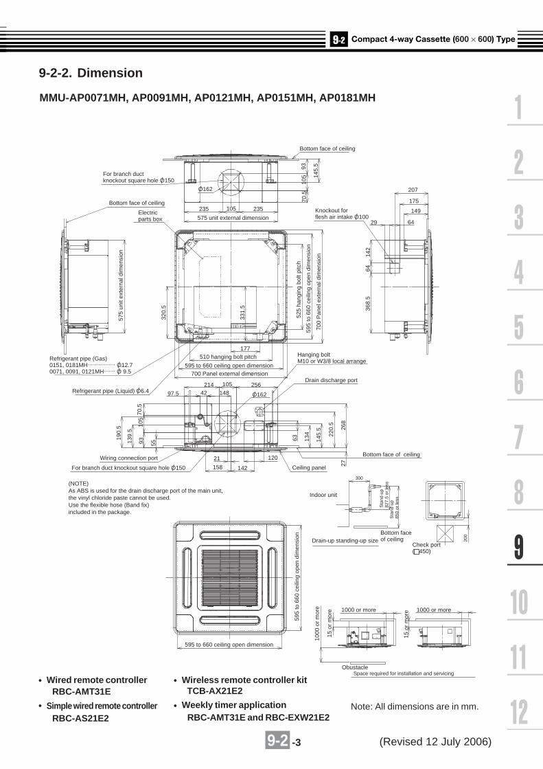
9-2 -3
9-2-2. Dimension
4-way air Discharge Cassete Type
Mode l name
MMU-AP0151MH
MMU-AP0181MH
MMU-AP0071MH
MMU-AP0091MH
MMU-AP0121MH
Arialb1i0c0p34;TOSHIBA CARRIER CORPORATION
Check port( 450)
For branch ductknockout square hole O/ 150
Knockout forflesh air intake O/ 100
700
Pan
el e
xter
nal d
imen
sion
595
to 6
60 c
eilin
g op
en d
imen
sion
525
hang
ing
bolt
pitc
h
Bottom face of ceiling
Electricparts box 575 unit external dimension
177
Bottom face of ceiling
235 235
207
29
175
149
64
70.5
142
6436
8.5
320.
5
Refrigerant pipe (Gas)0151, 0181MH................. O/ 12.70071, 0091, 0121MH....... O/ 9.5
97.5
70.5
105
55
63 134
145.
5
220.
5
268
27
93139.
5
190.
5
214
O/ 162
256105
42
142
120
158
21
148Refrigerant pipe (Liquid) O/ 6.4
Wiring connection port
(NOTE)As ABS is used for the drain discharge port of the main unit,the vinyl chloride paste cannot be used.Use the flexible hose (Band fix)included in the package.
575
unit
exte
rnal
dim
ensi
on
331.
5
510 hanging bolt pitch
595 to 660 ceiling open dimension700 Panel external dimension
Hanging boltM10 or W3/8 local arrange
Drain discharge port
Bottom face of ceiling
Ceiling panel
Indoor unit
Drain-up standing-up size
595
to 6
60 c
eilin
g op
en d
imen
sion
1000
or
mor
e
15 o
r m
ore
15 o
r m
ore1000 or more 1000 or more
ObustacleSpace required for installation and servicing
595 to 660 ceiling open dimension
Bottom faceof ceiling 20
0
Sta
nd-u
p82
7.5
or le
ssS
tand
-up
850
or le
ss
300
105
93
145.
5
105
O/ 162
For branch duct knockout square hole O/ 150
Note: All dimensions are in mm.
Wired remote controller RBC-AMT31E
Simple wired remote controller RBC-AS21E2
Wireless remote controller kit TCB-AX21E2
Weekly timer application RBC-AMT31E and RBC-EXW21E2
MMU-AP0071MH, AP0091MH, AP0121MH, AP0151MH, AP0181MH
(Revised 12 July 2006)
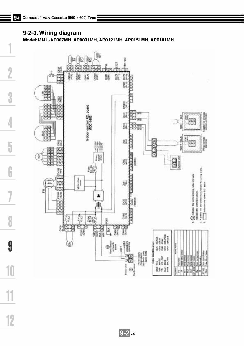
9-2 -4
9-2-3. Wiring diagramModel:MMU-AP007MH, AP0091MH, AP0121MH, AP0151MH, AP0181MH
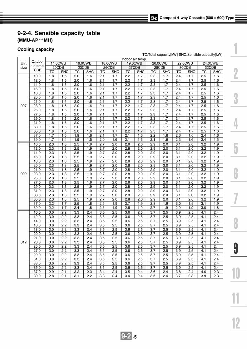
9-2 -5
TC:Total capacity[kW] SHC:Sensible capacity[kW]Indoor air temp.
Unit 14.0CWB 16.0CWB 18.0CWB 19.0CWB 20.0CWB 22.0CWB 24.0CWBsize 20CDB 23CDB 26CDB 27CDB 28CDB 30CDB 32CDB
TC SHC TC SHC TC SHC TC SHC TC SHC TC SHC TC SHC10.0 1.8 1.5 2.0 1.6 2.1 1.7 2.2 1.7 2.3 1.7 2.4 1.7 2.5 1.612.0 1.8 1.5 2.0 1.6 2.1 1.7 2.2 1.7 2.3 1.7 2.4 1.7 2.5 1.614.0 1.8 1.5 2.0 1.6 2.1 1.7 2.2 1.7 2.3 1.7 2.4 1.7 2.5 1.616.0 1.8 1.5 2.0 1.6 2.1 1.7 2.2 1.7 2.3 1.7 2.4 1.7 2.5 1.618.0 1.8 1.5 2.0 1.6 2.1 1.7 2.2 1.7 2.3 1.7 2.4 1.7 2.5 1.620.0 1.8 1.5 2.0 1.6 2.1 1.7 2.2 1.7 2.3 1.7 2.4 1.7 2.5 1.621.0 1.8 1.5 2.0 1.6 2.1 1.7 2.2 1.7 2.3 1.7 2.4 1.7 2.5 1.6
007 23.0 1.8 1.5 2.0 1.6 2.1 1.7 2.2 1.7 2.3 1.7 2.4 1.7 2.5 1.625.0 1.8 1.5 2.0 1.6 2.1 1.7 2.2 1.7 2.3 1.7 2.4 1.7 2.5 1.627.0 1.8 1.5 2.0 1.6 2.1 1.7 2.2 1.7 2.3 1.7 2.4 1.7 2.5 1.629.0 1.8 1.5 2.0 1.6 2.1 1.7 2.2 1.7 2.3 1.7 2.4 1.7 2.5 1.631.0 1.8 1.5 2.0 1.6 2.1 1.7 2.2 1.7 2.3 1.7 2.4 1.7 2.5 1.633.0 1.8 1.5 2.0 1.6 2.1 1.7 2.2 1.7 2.3 1.7 2.4 1.7 2.5 1.635.0 1.8 1.5 2.0 1.6 2.1 1.7 2.2 1.7 2.3 1.7 2.4 1.7 2.5 1.637.0 1.7 1.5 1.9 1.6 2.1 1.7 2.1 1.6 2.2 1.6 2.3 1.6 2.4 1.639.0 1.7 1.4 1.9 1.5 2.0 1.6 2.1 1.6 2.1 1.6 2.3 1.6 2.4 1.510.0 2.3 1.8 2.5 1.9 2.7 2.0 2.8 2.0 2.9 2.0 3.1 2.0 3.2 1.912.0 2.3 1.8 2.5 1.9 2.7 2.0 2.8 2.0 2.9 2.0 3.1 2.0 3.2 1.914.0 2.3 1.8 2.5 1.9 2.7 2.0 2.8 2.0 2.9 2.0 3.1 2.0 3.2 1.916.0 2.3 1.8 2.5 1.9 2.7 2.0 2.8 2.0 2.9 2.0 3.1 2.0 3.2 1.918.0 2.3 1.8 2.5 1.9 2.7 2.0 2.8 2.0 2.9 2.0 3.1 2.0 3.2 1.920.0 2.3 1.8 2.5 1.9 2.7 2.0 2.8 2.0 2.9 2.0 3.1 2.0 3.2 1.921.0 2.3 1.8 2.5 1.9 2.7 2.0 2.8 2.0 2.9 2.0 3.1 2.0 3.2 1.9
009 23.0 2.3 1.8 2.5 1.9 2.7 2.0 2.8 2.0 2.9 2.0 3.1 2.0 3.2 1.925.0 2.3 1.8 2.5 1.9 2.7 2.0 2.8 2.0 2.9 2.0 3.1 2.0 3.2 1.927.0 2.3 1.8 2.5 1.9 2.7 2.0 2.8 2.0 2.9 2.0 3.1 2.0 3.2 1.929.0 2.3 1.8 2.5 1.9 2.7 2.0 2.8 2.0 2.9 2.0 3.1 2.0 3.2 1.931.0 2.3 1.8 2.5 1.9 2.7 2.0 2.8 2.0 2.9 2.0 3.1 2.0 3.2 1.933.0 2.3 1.8 2.5 1.9 2.7 2.0 2.8 2.0 2.9 2.0 3.1 2.0 3.2 1.935.0 2.3 1.8 2.5 1.9 2.7 2.0 2.8 2.0 2.9 2.0 3.1 2.0 3.2 1.937.0 2.2 1.7 2.5 1.8 2.6 1.9 2.7 1.9 2.8 1.9 3.0 1.9 3.1 1.939.0 2.2 1.7 2.4 1.8 2.6 1.9 2.6 1.9 2.7 1.9 2.9 1.9 3.0 1.810.0 3.0 2.2 3.3 2.4 3.5 2.5 3.6 2.5 3.7 2.5 3.9 2.5 4.1 2.412.0 3.0 2.2 3.3 2.4 3.5 2.5 3.6 2.5 3.7 2.5 3.9 2.5 4.1 2.414.0 3.0 2.2 3.3 2.4 3.5 2.5 3.6 2.5 3.7 2.5 3.9 2.5 4.1 2.416.0 3.0 2.2 3.3 2.4 3.5 2.5 3.6 2.5 3.7 2.5 3.9 2.5 4.1 2.418.0 3.0 2.2 3.3 2.4 3.5 2.5 3.6 2.5 3.7 2.5 3.9 2.5 4.1 2.420.0 3.0 2.2 3.3 2.4 3.5 2.5 3.6 2.5 3.7 2.5 3.9 2.5 4.1 2.421.0 3.0 2.2 3.3 2.4 3.5 2.5 3.6 2.5 3.7 2.5 3.9 2.5 4.1 2.4
012 23.0 3.0 2.2 3.3 2.4 3.5 2.5 3.6 2.5 3.7 2.5 3.9 2.5 4.1 2.425.0 3.0 2.2 3.3 2.4 3.5 2.5 3.6 2.5 3.7 2.5 3.9 2.5 4.1 2.427.0 3.0 2.2 3.3 2.4 3.5 2.5 3.6 2.5 3.7 2.5 3.9 2.5 4.1 2.429.0 3.0 2.2 3.3 2.4 3.5 2.5 3.6 2.5 3.7 2.5 3.9 2.5 4.1 2.431.0 3.0 2.2 3.3 2.4 3.5 2.5 3.6 2.5 3.7 2.5 3.9 2.5 4.1 2.433.0 3.0 2.2 3.3 2.4 3.5 2.5 3.6 2.5 3.7 2.5 3.9 2.5 4.1 2.435.0 3.0 2.2 3.3 2.4 3.5 2.5 3.6 2.5 3.7 2.5 3.9 2.5 4.1 2.437.0 2.9 2.1 3.2 2.3 3.4 2.4 3.5 2.4 3.6 2.4 3.8 2.4 4.0 2.339.0 2.8 2.1 3.1 2.2 3.3 2.4 3.4 2.4 3.5 2.4 3.7 2.3 3.9 2.3
tOu doorair temp.
CDB
9-2-4. Sensible capacity table(MMU-AP***MH)
Cooling capacity

9-2 -6
Cooling capacity (cont.)
10.0 4.6 3.2 5.1 3.4 5.4 3.6 5.6 3.6 5.8 3.6 6.1 3.6 6.4 3.512.0 4.6 3.2 5.1 3.4 5.4 3.6 5.6 3.6 5.8 3.6 6.1 3.6 6.4 3.514.0 4.6 3.2 5.1 3.4 5.4 3.6 5.6 3.6 5.8 3.6 6.1 3.6 6.4 3.516.0 4.6 3.2 5.1 3.4 5.4 3.6 5.6 3.6 5.8 3.6 6.1 3.6 6.4 3.518.0 4.6 3.2 5.1 3.4 5.4 3.6 5.6 3.6 5.8 3.6 6.1 3.6 6.4 3.520.0 4.6 3.2 5.1 3.4 5.4 3.6 5.6 3.6 5.8 3.6 6.1 3.6 6.4 3.521.0 4.6 3.2 5.1 3.4 5.4 3.6 5.6 3.6 5.8 3.6 6.1 3.6 6.4 3.5
018 23.0 4.6 3.2 5.1 3.4 5.4 3.6 5.6 3.6 5.8 3.6 6.1 3.6 6.4 3.525.0 4.6 3.2 5.1 3.4 5.4 3.6 5.6 3.6 5.8 3.6 6.1 3.6 6.4 3.527.0 4.6 3.2 5.1 3.4 5.4 3.6 5.6 3.6 5.8 3.6 6.1 3.6 6.4 3.529.0 4.6 3.2 5.1 3.4 5.4 3.6 5.6 3.6 5.8 3.6 6.1 3.6 6.4 3.531.0 4.6 3.2 5.1 3.4 5.4 3.6 5.6 3.6 5.8 3.6 6.1 3.6 6.4 3.533.0 4.6 3.2 5.1 3.4 5.4 3.6 5.6 3.6 5.8 3.6 6.1 3.6 6.4 3.535.0 4.6 3.2 5.1 3.4 5.4 3.6 5.6 3.6 5.8 3.6 6.1 3.6 6.4 3.537.0 4.5 3.1 4.9 3.3 5.3 3.5 5.4 3.5 5.6 3.5 5.9 3.5 6.2 3.439.0 4.3 3.0 4.8 3.2 5.1 3.4 5.3 3.4 5.4 3.4 5.7 3.4 6.0 3.3
Indoor air temp.Unit 14.0CWB 16.0CWB 18.0CWB 19.0CWB 20.0CWB 22.0CWB 24.0CWBsize 20CDB 23CDB 26CDB 27CDB 28CDB 30CDB 32CDB
Outdoorair temp.
CDB TC SHC TC SHC TC SHC TC SHC TC SHC TC SHC TC SHC10.0 3.7 2.7 4.1 2.9 4.4 3.1 4.5 3.1 4.6 3.1 4.9 3.1 5.1 3.012.0 3.7 2.7 4.1 2.9 4.4 3.1 4.5 3.1 4.6 3.1 4.9 3.1 5.1 3.014.0 3.7 2.7 4.1 2.9 4.4 3.1 4.5 3.1 4.6 3.1 4.9 3.1 5.1 3.016.0 3.7 2.7 4.1 2.9 4.4 3.1 4.5 3.1 4.6 3.1 4.9 3.1 5.1 3.018.0 3.7 2.7 4.1 2.9 4.4 3.1 4.5 3.1 4.6 3.1 4.9 3.1 5.1 3.020.0 3.7 2.7 4.1 2.9 4.4 3.1 4.5 3.1 4.6 3.1 4.9 3.1 5.1 3.021.0 3.7 2.7 4.1 2.9 4.4 3.1 4.5 3.1 4.6 3.1 4.9 3.1 5.1 3.0
015 23.0 3.7 2.7 4.1 2.9 4.4 3.1 4.5 3.1 4.6 3.1 4.9 3.1 5.1 3.025.0 3.7 2.7 4.1 2.9 4.4 3.1 4.5 3.1 4.6 3.1 4.9 3.1 5.1 3.027.0 3.7 2.7 4.1 2.9 4.4 3.1 4.5 3.1 4.6 3.1 4.9 3.1 5.1 3.029.0 3.7 2.7 4.1 2.9 4.4 3.1 4.5 3.1 4.6 3.1 4.9 3.1 5.1 3.031.0 3.7 2.7 4.1 2.9 4.4 3.1 4.5 3.1 4.6 3.1 4.9 3.1 5.1 3.033.0 3.7 2.7 4.1 2.9 4.4 3.1 4.5 3.1 4.6 3.1 4.9 3.1 5.1 3.035.0 3.7 2.7 4.1 2.9 4.4 3.1 4.5 3.1 4.6 3.1 4.9 3.1 5.1 3.037.0 3.6 2.7 4.0 2.8 4.2 3.0 4.4 3.0 4.5 3.0 4.7 3.0 5.0 2.939.0 3.5 2.6 3.8 2.8 4.1 2.9 4.2 2.9 4.4 2.9 4.6 2.9 4.8 2.8

9-2 -7
Heating capacitySHC : Sensible Heat Capacity (kW)
UnitOutdoor Indoor air temp. °CDB
size air temp. 16.0 18.0 20.0 22.0 24.0
°CWB SHC SHC SHC SHC SHC-15.0 1.6 1.5 1.5 1.5 1.4-13.0 1.7 1.6 1.6 1.6 1.5-11.0 1.8 1.7 1.7 1.7 1.6-10.0 1.8 1.8 1.8 1.7 1.7-8.0 1.9 1.9 1.9 1.8 1.8-6.0 2.0 2.0 2.0 1.9 1.9-4.0 2.1 2.1 2.0 2.0 1.9
007 -2.0 2.2 2.2 2.1 2.1 2.00.0 2.3 2.3 2.2 2.2 2.12.0 2.4 2.4 2.3 2.3 2.24.0 2.5 2.5 2.4 2.4 2.36.0 2.6 2.6 2.5 2.4 2.48.0 2.6 2.6 2.5 2.4 2.4
10.0 2.6 2.6 2.5 2.4 2.412.0 2.6 2.6 2.5 2.4 2.414.0 2.6 2.6 2.5 2.4 2.4-15.0 2.0 2.0 1.9 1.9 1.8-13.0 2.1 2.1 2.1 2.0 1.9-11.0 2.3 2.2 2.2 2.1 2.1-10.0 2.3 2.3 2.2 2.2 2.1-8.0 2.5 2.4 2.4 2.3 2.3-6.0 2.6 2.6 2.5 2.4 2.4-4.0 2.7 2.7 2.6 2.6 2.5
009 -2.0 2.9 2.8 2.7 2.7 2.60.0 3.0 2.9 2.9 2.8 2.72.0 3.1 3.0 3.0 2.9 2.84.0 3.2 3.2 3.1 3.0 2.96.0 3.3 3.3 3.2 3.1 3.08.0 3.3 3.3 3.2 3.1 3.0
10.0 3.3 3.3 3.2 3.1 3.012.0 3.3 3.3 3.2 3.1 3.014.0 3.3 3.3 3.2 3.1 3.0-15.0 2.5 2.5 2.4 2.3 2.3-13.0 2.7 2.6 2.6 2.5 2.4-11.0 2.8 2.8 2.7 2.7 2.6-10.0 2.9 2.9 2.8 2.7 2.7-8.0 3.1 3.0 3.0 2.9 2.8-6.0 3.3 3.2 3.1 3.0 3.0-4.0 3.4 3.3 3.3 3.2 3.1
012 -2.0 3.6 3.5 3.4 3.3 3.30.0 3.7 3.7 3.6 3.5 3.42.0 3.9 3.8 3.7 3.6 3.54.0 4.0 3.9 3.9 3.8 3.76.0 4.2 4.1 4.0 3.9 3.88.0 4.2 4.1 4.0 3.9 3.8
10.0 4.2 4.1 4.0 3.9 3.812.0 4.2 4.1 4.0 3.9 3.814.0 4.2 4.1 4.0 3.9 3.8

9-2 -8
Unit Outdoor Indoor air temp. °CDB
size air temp. 16.0 18.0 20.0 22.0 24.0
°CWB SHC SHC SHC SHC SHC-15.0 3.1 3.1 3.0 2.9 2.9-13.0 3.3 3.3 3.2 3.1 3.0-11.0 3.6 3.5 3.4 3.3 3.2-10.0 3.7 3.6 3.5 3.4 3.3-8.0 3.9 3.8 3.7 3.6 3.5-6.0 4.1 4.0 3.9 3.8 3.7-4.0 4.3 4.2 4.1 4.0 3.9
015 -2.0 4.5 4.4 4.3 4.2 4.10.0 4.7 4.6 4.5 4.4 4.22.0 4.8 4.7 4.6 4.5 4.44.0 5.0 4.9 4.8 4.7 4.66.0 5.2 5.1 5.0 4.9 4.88.0 5.2 5.1 5.0 4.9 4.8
10.0 5.2 5.1 5.0 4.9 4.812.0 5.2 5.1 5.0 4.9 4.814.0 5.2 5.1 5.0 4.9 4.8-15.0 3.9 3.9 3.8 3.7 3.6-13.0 4.2 4.1 4.0 3.9 3.8-11.0 4.5 4.4 4.3 4.2 4.1-10.0 4.6 4.5 4.4 4.3 4.2-8.0 4.9 4.8 4.7 4.6 4.4-6.0 5.1 5.0 4.9 4.8 4.7-4.0 5.4 5.3 5.2 5.0 4.9
018 -2.0 5.6 5.5 5.4 5.3 5.10.0 5.9 5.8 5.6 5.5 5.32.0 6.1 6.0 5.9 5.7 5.64.0 6.3 6.2 6.1 5.9 5.86.0 6.6 6.4 6.3 6.1 6.08.0 6.6 6.4 6.3 6.1 6.0
10.0 6.6 6.4 6.3 6.1 6.012.0 6.6 6.4 6.3 6.1 6.014.0 6.6 6.4 6.3 6.1 6.0
Heating capacity (cont.)

9-2 -9
0 1 2 3 4 5m
0.7m/s
0.5m/s
0.3m/s
2.7m
1
2
0 1 2 3 4 5m
0.7m/s
0.5m/s
0.3m/s
2.7m
1
2
0 1 2 3 4 5m
0.7m/s
0.5m/s
0.3m/s
2.7m
1
2
0 1 2 3 4 5m
0.7m/s
0.5m/s
0.3m/s
3.2m
1
2
3
0 1 2 3 4 5m
0.7m/s
0.5m/s
0.3m/s
2.9m
1
2
3
0 1 2 3 4 5m
0.7m/s
0.5m/s
0.3m/s
3.2m
1
2
3
9-2-5. Air throw distance chartAir Speed Distribution
MMU-AP0071MH MMU-AP0091MH
MMU-AP0121MH MMU-AP0151MH
MMU-AP0181MH MMU-AP0151MH,MMU-AP0181MH(High ceiling mode)
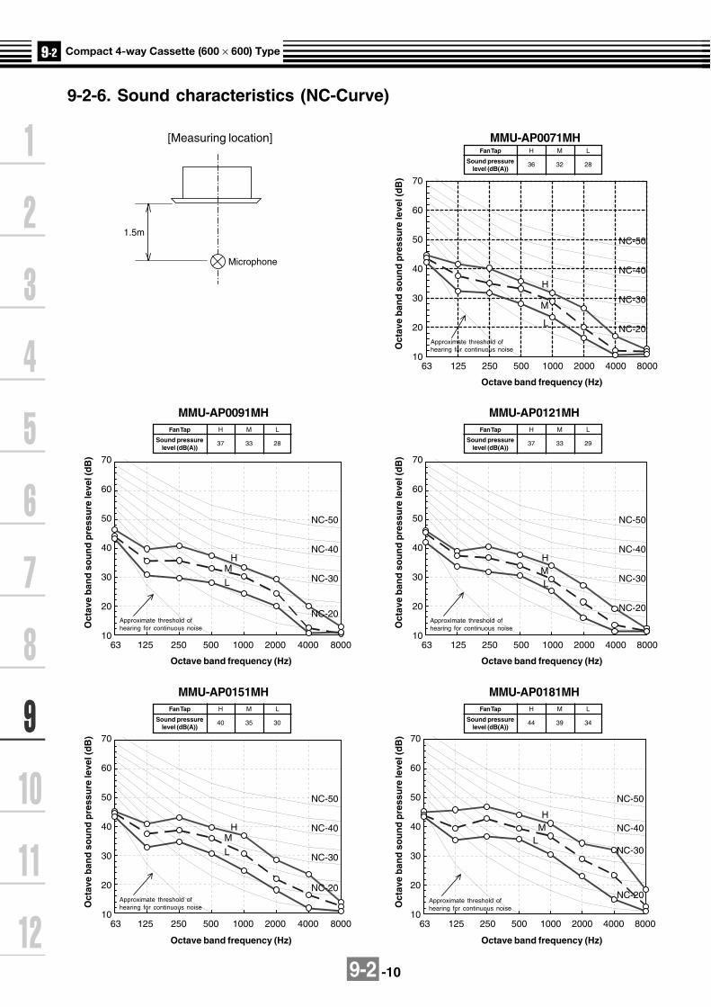
9-2 -10
9-2-6. Sound characteristics (NC-Curve)
1.5m
Microphone
70
60
50
40
30
20
10
NC-50
NC-40
NC-30
NC-20
H
M
L
63 125 250 500 1000 2000 4000 8000
70
60
50
40
30
20
10
NC-50
NC-40
NC-30
NC-20
HML
63 125 250 500 1000 2000 4000 8000
70
60
50
40
30
20
10
NC-50
NC-40
NC-30
NC-20
HM
L
63 125 250 500 1000 2000 4000 8000
70
60
50
40
30
20
10
NC-50
NC-40
NC-30
NC-20
HM
L
63 125 250 500 1000 2000 4000 8000
70
60
50
40
30
20
10
NC-50
NC-40
NC-30
NC-20
HM
L
63 125 250 500 1000 2000 4000 8000
MMU-AP0071MH
Oct
ave
ban
d s
ou
nd
pre
ssu
re le
vel (
dB
)
Octave band frequency (Hz)
Approximate threshold ofhearing for continuous noise
Fan Tap
Sound pressurelevel (dB(A))
H
36
M
32
L
28
MMU-AP0121MHO
ctav
e b
and
so
un
d p
ress
ure
leve
l (d
B)
Octave band frequency (Hz)
Approximate threshold ofhearing for continuous noise
Fan Tap
Sound pressurelevel (dB(A))
H
37
M
33
L
29
MMU-AP0091MH
Oct
ave
ban
d s
ou
nd
pre
ssu
re le
vel (
dB
)
Octave band frequency (Hz)
Approximate threshold ofhearing for continuous noise
Fan Tap
Sound pressurelevel (dB(A))
H
37
M
33
L
28
MMU-AP0181MH
Oct
ave
ban
d s
ou
nd
pre
ssu
re le
vel (
dB
)
Octave band frequency (Hz)
Approximate threshold ofhearing for continuous noise
Fan Tap
Sound pressurelevel (dB(A))
H
44
M
39
L
34
MMU-AP0151MH
Oct
ave
ban
d s
ou
nd
pre
ssu
re le
vel (
dB
)
Octave band frequency (Hz)
Approximate threshold ofhearing for continuous noise
Fan Tap
Sound pressurelevel (dB(A))
H
40
M
35
L
30
[Measuring location]

9-2 -11
9-2-7. Accessories
Apperarance
Standard accessories
Remote controller
Weekly timer application
Model Name
RBC-AMT31E
RBC-AS21E2
TCB-AX21E2
RBC-AMT31E and RBC-EXW21E2
Wired remote controller
Simple wired remote controller
Wireless remote controller kit
Central remote controller TCB-SC642TLE2
ON-OFF controller TCB-CC163TLE2
Qty Shape Use
M5 x 16
Installation Manual
Heat insulating pipe
Installation pattern
Installation gauge
Pattern fixing screw
Part name
Heat insulator
Heat insulator
Flexible hose
Hose band
Washer
1
2
1
2
4
1
1
1
1
8
For heat insulating of drain connecting section
For hanging down unit
For connecting drain pipe
For centering the drain pipe
For sealing the wire connection opening
(Be sure to hand over to customer)
For heat insulating of pipe connecting section
For confirmation of ceiling opening and main unit position
For positioning of ceiling position (united with installation pattern)
For attaching pattern

9-2 -12
Ceiling panel
RBC-UM11PG(W)E
Auxiliary fresh air flange
TCB-FF101URE2
Name Model name Note
Required accessory
For easy fresh air intake by using the knockout hole of indoor unit.(dia=100mm)
RBC-UM11PG(W)E
TCB-FF101URE2
Ceiling panel
Auxiliary Fresh Air Flange
Optional accessories
(Revised 19 May 2006)

9-3 -1
9-3-1. Specifications 50Hz
Note 1 : The cooling capacities and electrical characteristics are measured under the conditions specified by JIS B 8615 based on thereference piping. The reference piping consists of 5 m of main piping and 2.5 m of branch piping connected with 0 meter height.
Note 2 : The sound level are measured in an anechoic chamber in accordance with JIS B8616. Normally, the values measured in theactual operating environment become larger than the indicated values due to the effects of external sound.
Note : Rated conditions Cooling : Indoor air temperature 27oC DB/19oC WB, Outdoor air temperature 35oC DBHeating : Indoor air temperature 20oC DB, Outdoor air temperature 7oC DB/6oC WB
Model name MMU-
Cooling/Heating capacity (Note 1)
(kW)
Electricalcharacteris-t ics
Power supply
Running current (A)
Power consumption (kW)
Power factor (%)
Starting current (A)
Appearance
Main unit
Ceilingpanel
Model
Panel color
Outerdimension
Main unit
Ceilingpanel
Height (mm)
Width (mm)
Depth (mm)
Height (mm)
Width (mm)
Depth (mm)
Total weighMain unit (kg)
Ceiling panel (kg)
Heat exchanger
Soundproof/Heat-insulatingmaterial
Fan unit
Fan
Standard air flow(High/Mid/Low)
(m3/h)
Motor (W)
Air filter
Controller
Connectingpipe
Gas side (mm)
Liquid side (mm)
Drain port (Nominal dia. mm)
Sound pressure level (Note 2)(High/Mid/Low) (dB(A))
AP0071WH
2.2/2.5
1 phase 50Hz 230V (220-240V) (Separate power supply for indoor units is required.)
Heat-insulating material attached Zinc hot dipping steel plate
398
830
33
8
Non-flammable insulation
Finned tube
Centrifugal fan
570/510/450
O/ 9.5
O/ 6.4
25 (Polyvinyl chloride tube)
34/32/30
AP0091WH
2.8/3.2
AP0121WH
3.6/4.0
AP0151WH
4.5/5.0
AP0181WH
5.6/6.3
AP0241WH
7.1/8.0
AP0271WH
8.0/9.0
0.32
0.072
0.46
0.105
97 99
0.890.47 0.60
RBC-UW136PG RBC-UW266PG
Light ivory (Munsell 10Y 9/0.5)
1,350
550
1,000 1,520
650
44 48
11
780/700/600 1140/960/720
Standard filter (Long life filter)
Remote controller
O/ 15.9
O/ 9.5
O/ 12.7
35/33/30 38/35/33
53 39 53
AP0301WH
9.0/10.0
0.47
0.106
0.98
8
1260/1140/960
40/37/34
98
PMV Kit Not available
0.31
0.070
Specifications (50Hz)

9-3 -2
60Hz
Model name MMU-
(kW)Cooling/Heating capacity (Note 1)
AP0071WH
2.2/2.5
Power supply
Electricalcharacteris-tics
Running current
Powerconsumption
Power factor
Starting current
Main unit
Model
Panel color
AppearanceCeilingpanel
Height
Width
Depth
Height
Width
Depth
Mainunit
Ceilingpanel
Outerdimension
Main unit
Ceiling panelTotal weight
Heat exchanger
Soundproof/Heat-insulating material
Fan unit
Fan
Motor
Standard air flow(High/Mid./Low)
Air filter
Controller
Gas side
Liquid side
Drain port
Connectingpipe
Sound pressure level(Note 2)(High/Mid./Low)
(A)
(kW)
(%)
(A)
(mm)
(mm)
(mm)
(mm)
(mm)
(mm)
(kg)
(kg)
(W)
(m3/h)
(mm)
(mm)
(Nominal dia.mm)
(dB(A))
AP0091WH
2.8/3.2
AP0121WH
3.6/4.0
AP0151WH
4.5/5.0
AP0181WH
5.6/6.3
AP0241WH
7.1/8.0
AP0271WH
8.0/9.0
AP0301WH
9.0/10.0
1 phase 60Hz 220V (Separate power supply for indoor units is required.)
0.33 0.38 0.53 0.58
0.070 0.076 0.115 0.123
97 90 99 96
0.46 0.59 0.87 0.96
Heat-insulating material attached Zinc hot dipping steel plate
RBC-UW136PG RBC-UW266PG
Light ivory (Munsell 10Y 9/0.5)
398
830 1.350
550
8
1,000 1,520
650
33 44 48
8 11
Finned tube
Non-flammable insulation
Centrifugal fan
570/510/450 780/700/600 1,140/960/720 1,260/1,140/960
53 39 53
Remote controller
Standard filter (Long life filter)
25 (Polyvinyl chloride tube)
O/ 9.5 O/ 12.7 O/ 15.9
O/ 6.4 O/ 9.5
34/32/30 35/33/30 38/35/33 40/37/34
Note 1 : The cooling capacities and electrical characteristics are measured under the conditions specified by JIS B 8615 based on thereference piping. The reference piping consists of 5 m of main piping and 2.5 m of branch piping connected with 0 meter height.
Note 2 : The sound levels are measured in an anechoic chamber in accordance with JIS B8616. Normally, the values measured inthe actual operating environment become larger than the indicated values due to the effects of external sound.
Note : Rated conditions Cooling : Indoor air temperature 27OC DB/19OC WB, Outdoor air temperature 35OC DBHeating : Indoor air temperature 20OC DB, Outdoor air temperature 7OC DB/6OC WB
PMV Kit Not available
Specifications (60Hz)
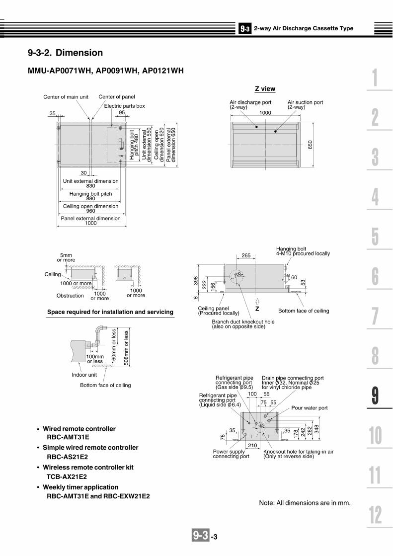
9-3 -3
Electric parts box
Z53
60
30
9535
265
1000
100
75 55
56
22239
8
156
8
650
Center of main unit Center of panel
Unit external dimension830
Hanging bolt pitch880
Ceiling open dimension960
Panel external dimension1000
Han
ging
bol
tpi
tch
480
Uni
t ext
erna
ldi
men
sion
550
Cei
ling
open
dim
ensi
on 6
20P
anel
ext
erna
ldi
men
sion
650
Z view
Air suction port(2-way)
Air discharge port(2-way)
1000 or more
Ceiling
1000or more
5mmor more
1000or moreObstruction
Hanging bolt4-M10 procured locally
Branch duct knockout hole(also on opposite side)
Ceiling panel(Procured locally) Bottom face of ceiling
¯ 200
Space required for installation and servicing
508m
m o
r le
ss
160m
m o
r le
ss
100mmor less
Bottom face of ceiling
Indoor unit
Power supply connecting port
178
242
282
348
35
78
35
210Knockout hole for taking-in air(Only at reverse side)
Refrigerant pipe connecting port(Gas side O/ 9.5)
Refrigerant pipe connecting port(Liquid side O/ 6.4)
Drain pipe connecting portInner O/ 32, Nominal O/ 25for vinyl chloride pipe
Pour water port
¯ 150
Note: All dimensions are in mm.
Wired remote controller RBC-AMT31E
Simple wired remote controller RBC-AS21E2
Wireless remote controller kit TCB-AX21E2
Weekly timer application RBC-AMT31E and RBC-EXW21E2
9-3-2. Dimension
MMU-AP0071WH, AP0091WH, AP0121WH

9-3 -4
Power supply connecting port
Branch duct knockout hole(Also on opposite side)
650
35 95
30
Z
53
¯ 20060
295
22239
8
156
8
178
242
282
348
35
7555
56
100
78
35
210
Center of main unit
1000 or more
Center of panel
Electric parts box
Unit external dimension 1350
Hanging bolt pitch 1400
Ceiling open dimension 1480
Ceiling 1000or more
5mm
or m
ore
Panel external dimension 1520
1000or more
Han
ging
bol
tpi
tch
480
Uni
t ext
erna
ldi
men
sion
550
Cei
ling
open
dim
ensi
on 6
20P
anel
ext
erna
ldi
men
sion
650
Z view
Air suction port(2-way)
Air discharge port(2-way)
Obstruction
Space required for installation and servicing
ModelMMU-AP0151WH to AP0181WHMMU-AP0241WH to AP0301WH
AO/ 6.4O/ 9.5
BO/ 12.7O/ 15.9
Hanging bolt4-M10 procured locally
Ceiling panel(Procured locally)
Bottom face of ceiling
508m
m o
r le
ss
160m
m o
r le
ss
100mmor less
Bottom face of ceiling
Knockout hole for air intake(Only at reverse side)
Refrigerant pipe connecting port(Gas side O/ B)
Refrigerant pipe connecting port(Liquid side O/ A)
Drain pipe connecting portInner O/ 32, Nominal O/ 25for vinyl chloride pipe
Pour water port
¯ 150
MMU-AP0151WH, AP0181WH, AP0241WH, AP0271WH. AP0301WH
Note: All dimensions are in mm.
Wired remote controller RBC-AMT31E
Simple wired remote controller RBC-AS21E2
Wireless remote controller kit TCB-AX21E2
Weekly timer application RBC-AMT31E and RBC-EXW21E2

9-3 -5
Air suction port(2-way)
Air discharge port(2-way)Electric parts box
95
Z
23040
6
60
8
166 68
455 150
5 105
680
1898
16120
4 2.7
120
Center of main unit Center of panel
Unit external dimension 1650
Hanging bolt pitch 1700
Ceiling open dimension 1850
Panel external dimension 1898
5mm
or m
ore
Han
ging
bol
tpi
tch
510
Uni
t ext
erna
ldi
men
sion
620
Cei
ling
open
dim
ensi
on 6
50P
anel
ext
erna
ldi
men
sion
680
Z view
1000 or more
Ceiling 1000or more
1000or moreObstruction
Space required for installation and servicing
Hanging bolt4-M10 procured locally
Ceiling panel(Procured locally)
Branch duct knockout hole(Also on reverse side)
Bottom face of ceiling
¯20
0
¯20
0
• Wired remote controller (RBC-AMT21E)
516m
m o
r le
ss
160m
m o
r le
ss
Bottom face of ceiling
100mmor less
Power supply connecting port
186
250
290
356
15
7555
56
100
86
15
Knockout hole for air intake(Only at reverse side)
210
Refrigerant pipe connecting port(Gas side O/ 15.9)
Refrigerant pipe connecting port(Liquid side O/ 9.5)
Drain pipe connecting port(VP25)
Pour water port
¯ 150
MMU-AP0481WH*CHINA market only
Note: All dimensions are in mm.
Wired remote controller RBC-AMT31E
Simple wired remote controller RBC-AS21E2
Wireless remote controller kit TCB-AX21E2
Weekly timer application RBC-AMT31E and RBC-EXW21E2

9-3-6
9-3-3. Wirin
g d
iagram
Mo
del:M
MU
-AP
0071WH
, AP
0091WH
, AP
0121WH
, AP
0151WH
, AP
0181WH
,M
MU
-AP
0241WH
, AP
0271WH
, AP
0301WH
, AP
0481WH
CN104(YEL)
CN102(RED)
CN101(BLK)
5 4 3 2 15 4 3 2 1
9 8 7 69 8 7 6
FANCN083(WHI)
WHI
RED
DP(BLU)CN068
DM
CN304(GRY)
CN066(WHI)
CN067(BLK)
CN044(BRW)
12
12
TA12
12
TCJ12
12
TC2
CN100(BRW)
12
12
33
CN080(GRN) PNL
EXCT
12
CN073(RED)
12
FilterCN070(WHI)
CN081(BLK)
CN060(WHI)
Option
CN032(WHI)
CN075(WHI)
CN074(WHI)
TR
12
12345
12
3
TC1
1 2 3 4 5 6
CN061(YEL)
Fan drive1 2 3 4 5 61 2 3 4 5 6
1 2 31 2 31 2 3
1 21 2
1 2 31 2 3
1 2 31 2 3
4 5 6
1 2 3 4 5 61 2 3 4 5 6
1 2 3 4 5 61 2 3 4 5 6
CN050(WHI)
CN041(BLU)
CN040(BLU)
CN01(WHI)
CN02(BLU)
Network adaptor(Option)
1 21 2 3 4 5
1 21 2
3 32
1 1CN03(RED)MCC-1401
2 21 1
RY004123
12
12
RY002
RY006
RY007
RY005
1 2
BA YXS(N)R(L)
U2
1 2Remote controller
CN1(WHI)
Power supplySingle phase
220-240V 50Hz 220V 60Hz
Indoor unitEarth screw
Outdoor unit
BLU
BLU BLK
BLK
U1
U2U1
Flow selector unit earth
screw
Power supplycircuit
CN01(WHI)
CN02(YEL)
Sub P.C. boardMCC-1520
LM(GRN)CN033
LM
1 2 31 2 3
FS(RED)CN030
PMV(BLU)CN082
FS
1 2 31 2 3
1 2 31 2 3
4 5 64 5 6
6 4 36 4 3
1 2 51 2 5
RY001
TR
FuseT5.0A
250V~123
123
CN039(YEL)
123
123
1 21 2
PMV
12
12
34
34
56
56
77
9
FM
YE
L
BLU
OR
NBLK
H M L UL
RC
RED
Closed end connector
Line Filter
P301(BLK)
Symbol
FM
RC
LM
TR
TA
TC1,TC2,TCJ
RY001
RY002
RY004
RY005~007
FS
D M
PMV
Parts name
Fan motor
Running capacitor
Transformer
Louver motor
Indoor temp sensor
Temp sensor
Louver control relay
Drain control relay
Heater control relay
Fan motor control relay
Float switch
Drain pump motor
Pulse Motor Valve
Colorindication
RED : REDWHI : WHITEYEL : YELLOWBLU : BLUEBLK : BLACKGRY : GRAYPNK : PINKORN :ORANGEBRN : BROWNGRN : GREEN Indoor control P.C. board
1. indicates the terminal block, the letter insideindicates the terminal number.
2. A dotted line and broken line indicate the wiring on site.
3. indicates the control P.C. board.

9-3 -7
TC : Total Capacity (kW) SHC : Sensible Heat Capacity (kW)Indoor air temp.
Unit Outdoor 16.0˚CWB 18.0˚CWB 19.0˚CWB 20.0˚CWB 22.0˚CWB 24.0˚CWBsize air temp. 23˚CDB 26˚CDB 27˚CDB 28˚CDB 30˚CDB 32˚CDB
˚CDB TC SHC TC SHC TC SHC TC SHC TC SHC TC SHC10.0 2.0 1.6 2.1 1.7 2.2 1.7 2.3 1.7 2.4 1.7 2.5 1.612.0 2.0 1.6 2.1 1.7 2.2 1.7 2.3 1.7 2.4 1.7 2.5 1.614.0 2.0 1.6 2.1 1.7 2.2 1.7 2.3 1.7 2.4 1.7 2.5 1.616.0 2.0 1.6 2.1 1.7 2.2 1.7 2.3 1.7 2.4 1.7 2.5 1.618.0 2.0 1.6 2.1 1.7 2.2 1.7 2.3 1.7 2.4 1.7 2.5 1.620.0 2.0 1.6 2.1 1.7 2.2 1.7 2.3 1.7 2.4 1.7 2.5 1.621.0 2.0 1.6 2.1 1.7 2.2 1.7 2.3 1.7 2.4 1.7 2.5 1.6
007 23.0 2.0 1.6 2.1 1.7 2.2 1.7 2.3 1.7 2.4 1.7 2.5 1.625.0 2.0 1.6 2.1 1.7 2.2 1.7 2.3 1.7 2.4 1.7 2.5 1.627.0 2.0 1.6 2.1 1.7 2.2 1.7 2.3 1.7 2.4 1.7 2.5 1.629.0 2.0 1.6 2.1 1.7 2.2 1.7 2.3 1.7 2.4 1.7 2.5 1.631.0 2.0 1.6 2.1 1.7 2.2 1.7 2.3 1.7 2.4 1.7 2.5 1.633.0 2.0 1.6 2.1 1.7 2.2 1.7 2.3 1.7 2.4 1.7 2.5 1.635.0 2.0 1.6 2.1 1.7 2.2 1.7 2.3 1.7 2.4 1.7 2.5 1.637.0 2.0 1.6 2.1 1.7 2.2 1.7 2.2 1.7 2.4 1.7 2.5 1.639.0 1.9 1.5 2.0 1.6 2.1 1.6 2.2 1.6 2.3 1.6 2.4 1.510.0 2.5 1.9 2.7 2.0 2.8 2.0 2.9 2.0 3.1 2.0 3.2 1.912.0 2.5 1.9 2.7 2.0 2.8 2.0 2.9 2.0 3.1 2.0 3.2 1.914.0 2.5 1.9 2.7 2.0 2.8 2.0 2.9 2.0 3.1 2.0 3.2 1.916.0 2.5 1.9 2.7 2.0 2.8 2.0 2.9 2.0 3.1 2.0 3.2 1.918.0 2.5 1.9 2.7 2.0 2.8 2.0 2.9 2.0 3.1 2.0 3.2 1.920.0 2.5 1.9 2.7 2.0 2.8 2.0 2.9 2.0 3.1 2.0 3.2 1.921.0 2.5 1.9 2.7 2.0 2.8 2.0 2.9 2.0 3.1 2.0 3.2 1.9
009 23.0 2.5 1.9 2.7 2.0 2.8 2.0 2.9 2.0 3.1 2.0 3.2 1.925.0 2.5 1.9 2.7 2.0 2.8 2.0 2.9 2.0 3.1 2.0 3.2 1.927.0 2.5 1.9 2.7 2.0 2.8 2.0 2.9 2.0 3.1 2.0 3.2 1.929.0 2.5 1.9 2.7 2.0 2.8 2.0 2.9 2.0 3.1 2.0 3.2 1.931.0 2.5 1.9 2.7 2.0 2.8 2.0 2.9 2.0 3.1 2.0 3.2 1.933.0 2.5 1.9 2.7 2.0 2.8 2.0 2.9 2.0 3.1 2.0 3.2 1.935.0 2.5 1.9 2.7 2.0 2.8 2.0 2.9 2.0 3.1 2.0 3.2 1.937.0 2.5 1.9 2.7 2.0 2.7 2.0 2.8 2.0 3.0 1.9 3.1 1.939.0 2.4 1.8 2.6 1.9 2.7 1.9 2.8 1.9 2.9 1.9 3.1 1.810.0 3.3 2.2 3.5 2.3 3.6 2.3 3.7 2.3 3.9 2.3 4.1 2.212.0 3.3 2.2 3.5 2.3 3.6 2.3 3.7 2.3 3.9 2.3 4.1 2.214.0 3.3 2.2 3.5 2.3 3.6 2.3 3.7 2.3 3.9 2.3 4.1 2.216.0 3.3 2.2 3.5 2.3 3.6 2.3 3.7 2.3 3.9 2.3 4.1 2.218.0 3.3 2.2 3.5 2.3 3.6 2.3 3.7 2.3 3.9 2.3 4.1 2.220.0 3.3 2.2 3.5 2.3 3.6 2.3 3.7 2.3 3.9 2.3 4.1 2.221.0 3.3 2.2 3.5 2.3 3.6 2.3 3.7 2.3 3.9 2.3 4.1 2.2
012 23.0 3.3 2.2 3.5 2.3 3.6 2.3 3.7 2.3 3.9 2.3 4.1 2.225.0 3.3 2.2 3.5 2.3 3.6 2.3 3.7 2.3 3.9 2.3 4.1 2.227.0 3.3 2.2 3.5 2.3 3.6 2.3 3.7 2.3 3.9 2.3 4.1 2.229.0 3.3 2.2 3.5 2.3 3.6 2.3 3.7 2.3 3.9 2.3 4.1 2.231.0 3.3 2.2 3.5 2.3 3.6 2.3 3.7 2.3 3.9 2.3 4.1 2.233.0 3.3 2.2 3.5 2.3 3.6 2.3 3.7 2.3 3.9 2.3 4.1 2.235.0 3.3 2.2 3.5 2.3 3.6 2.3 3.7 2.3 3.9 2.3 4.1 2.237.0 3.2 2.1 3.4 2.3 3.5 2.3 3.6 2.3 3.8 2.2 4.0 2.239.0 3.1 2.0 3.4 2.2 3.5 2.2 3.6 2.2 3.8 2.1 3.9 2.110.0 4.1 2.9 4.4 3.1 4.5 3.1 4.6 3.1 4.9 3.1 5.1 3.012.0 4.1 2.9 4.4 3.1 4.5 3.1 4.6 3.1 4.9 3.1 5.1 3.014.0 4.1 2.9 4.4 3.1 4.5 3.1 4.6 3.1 4.9 3.1 5.1 3.016.0 4.1 2.9 4.4 3.1 4.5 3.1 4.6 3.1 4.9 3.1 5.1 3.018.0 4.1 2.9 4.4 3.1 4.5 3.1 4.6 3.1 4.9 3.1 5.1 3.020.0 4.1 2.9 4.4 3.1 4.5 3.1 4.6 3.1 4.9 3.1 5.1 3.021.0 4.1 2.9 4.4 3.1 4.5 3.1 4.6 3.1 4.9 3.1 5.1 3.0
015 23.0 4.1 2.9 4.4 3.1 4.5 3.1 4.6 3.1 4.9 3.1 5.1 3.025.0 4.1 2.9 4.4 3.1 4.5 3.1 4.6 3.1 4.9 3.1 5.1 3.027.0 4.1 2.9 4.4 3.1 4.5 3.1 4.6 3.1 4.9 3.1 5.1 3.029.0 4.1 2.9 4.4 3.1 4.5 3.1 4.6 3.1 4.9 3.1 5.1 3.031.0 4.1 2.9 4.4 3.1 4.5 3.1 4.6 3.1 4.9 3.1 5.1 3.033.0 4.1 2.9 4.4 3.1 4.5 3.1 4.6 3.1 4.9 3.1 5.1 3.035.0 4.1 2.9 4.4 3.1 4.5 3.1 4.6 3.1 4.9 3.1 5.1 3.037.0 4.0 2.9 4.3 3.0 4.4 3.0 4.5 3.0 4.8 3.0 5.0 2.939.0 3.9 2.8 4.2 2.9 4.3 2.9 4.4 2.9 4.7 2.9 4.9 2.8
9-3-4. Sensible capacity table(MMU-AP***WH)
Cooling capacity
(Revised 12 July 2006)

9-3 -8
Cooling capacity (cont.)
Indoor air temp.Unit Outdoor 16.0˚CWB 18.0˚CWB 19.0˚CWB 20.0˚CWB 22.0˚CWB 24.0˚CWBsize air temp. 23˚CDB 26˚CDB 27˚CDB 28˚CDB 30˚CDB 32˚CDB
˚CDB TC SHC TC SHC TC SHC TC SHC TC SHC TC SHC10.0 5.1 3.6 5.4 3.8 5.6 3.8 5.8 3.8 6.1 3.8 6.4 3.712.0 5.1 3.6 5.4 3.8 5.6 3.8 5.8 3.8 6.1 3.8 6.4 3.714.0 5.1 3.6 5.4 3.8 5.6 3.8 5.8 3.8 6.1 3.8 6.4 3.716.0 5.1 3.6 5.4 3.8 5.6 3.8 5.8 3.8 6.1 3.8 6.4 3.718.0 5.1 3.6 5.4 3.8 5.6 3.8 5.8 3.8 6.1 3.8 6.4 3.720.0 5.1 3.6 5.4 3.8 5.6 3.8 5.8 3.8 6.1 3.8 6.4 3.721.0 5.1 3.6 5.4 3.8 5.6 3.8 5.8 3.8 6.1 3.8 6.4 3.7
018 23.0 5.1 3.6 5.4 3.8 5.6 3.8 5.8 3.8 6.1 3.8 6.4 3.725.0 5.1 3.6 5.4 3.8 5.6 3.8 5.8 3.8 6.1 3.8 6.4 3.727.0 5.1 3.6 5.4 3.8 5.6 3.8 5.8 3.8 6.1 3.8 6.4 3.729.0 5.1 3.6 5.4 3.8 5.6 3.8 5.8 3.8 6.1 3.8 6.4 3.731.0 5.1 3.6 5.4 3.8 5.6 3.8 5.8 3.8 6.1 3.8 6.4 3.733.0 5.1 3.6 5.4 3.8 5.6 3.8 5.8 3.8 6.1 3.8 6.4 3.735.0 5.1 3.6 5.4 3.8 5.6 3.8 5.8 3.8 6.1 3.8 6.4 3.737.0 5.0 3.5 5.3 3.7 5.5 3.7 5.7 3.7 6.0 3.7 6.3 3.639.0 4.9 3.4 5.2 3.6 5.4 3.6 5.5 3.6 5.9 3.5 6.1 3.510.0 6.4 4.5 6.9 4.8 7.1 4.8 7.3 4.8 7.7 4.8 8.1 4.612.0 6.4 4.5 6.9 4.8 7.1 4.8 7.3 4.8 7.7 4.8 8.1 4.614.0 6.4 4.5 6.9 4.8 7.1 4.8 7.3 4.8 7.7 4.8 8.1 4.616.0 6.4 4.5 6.9 4.8 7.1 4.8 7.3 4.8 7.7 4.8 8.1 4.618.0 6.4 4.5 6.9 4.8 7.1 4.8 7.3 4.8 7.7 4.8 8.1 4.620.0 6.4 4.5 6.9 4.8 7.1 4.8 7.3 4.8 7.7 4.8 8.1 4.621.0 6.4 4.5 6.9 4.8 7.1 4.8 7.3 4.8 7.7 4.8 8.1 4.6
024 23.0 6.4 4.5 6.9 4.8 7.1 4.8 7.3 4.8 7.7 4.8 8.1 4.625.0 6.4 4.5 6.9 4.8 7.1 4.8 7.3 4.8 7.7 4.8 8.1 4.627.0 6.4 4.5 6.9 4.8 7.1 4.8 7.3 4.8 7.7 4.8 8.1 4.629.0 6.4 4.5 6.9 4.8 7.1 4.8 7.3 4.8 7.7 4.8 8.1 4.631.0 6.4 4.5 6.9 4.8 7.1 4.8 7.3 4.8 7.7 4.8 8.1 4.633.0 6.4 4.5 6.9 4.8 7.1 4.8 7.3 4.8 7.7 4.8 8.1 4.635.0 6.4 4.5 6.9 4.8 7.1 4.8 7.3 4.8 7.7 4.8 8.1 4.637.0 6.3 4.4 6.7 4.7 7.0 4.7 7.2 4.7 7.6 4.7 7.9 4.639.0 6.2 4.3 6.6 4.5 6.8 4.5 7.0 4.5 7.4 4.5 7.8 4.410.0 7.3 5.2 7.8 5.5 8.0 5.5 8.2 5.5 8.7 5.4 9.1 5.312.0 7.3 5.2 7.8 5.5 8.0 5.5 8.2 5.5 8.7 5.4 9.1 5.314.0 7.3 5.2 7.8 5.5 8.0 5.5 8.2 5.5 8.7 5.4 9.1 5.316.0 7.3 5.2 7.8 5.5 8.0 5.5 8.2 5.5 8.7 5.4 9.1 5.318.0 7.3 5.2 7.8 5.5 8.0 5.5 8.2 5.5 8.7 5.4 9.1 5.320.0 7.3 5.2 7.8 5.5 8.0 5.5 8.2 5.5 8.7 5.4 9.1 5.321.0 7.3 5.2 7.8 5.5 8.0 5.5 8.2 5.5 8.7 5.4 9.1 5.3
027 23.0 7.3 5.2 7.8 5.5 8.0 5.5 8.2 5.5 8.7 5.4 9.1 5.325.0 7.3 5.2 7.8 5.5 8.0 5.5 8.2 5.5 8.7 5.4 9.1 5.327.0 7.3 5.2 7.8 5.5 8.0 5.5 8.2 5.5 8.7 5.4 9.1 5.329.0 7.3 5.2 7.8 5.5 8.0 5.5 8.2 5.5 8.7 5.4 9.1 5.331.0 7.3 5.2 7.8 5.5 8.0 5.5 8.2 5.5 8.7 5.4 9.1 5.333.0 7.3 5.2 7.8 5.5 8.0 5.5 8.2 5.5 8.7 5.4 9.1 5.335.0 7.3 5.2 7.8 5.5 8.0 5.5 8.2 5.5 8.7 5.4 9.1 5.337.0 7.1 5.1 7.6 5.4 7.8 5.4 8.1 5.4 8.5 5.3 8.9 5.239.0 7.0 4.9 7.4 5.2 7.7 5.2 7.9 5.2 8.4 5.1 8.8 5.010.0 8.2 5.7 8.7 6.0 9.0 6.0 9.3 6.0 9.8 5.9 10.3 5.812.0 8.2 5.7 8.7 6.0 9.0 6.0 9.3 6.0 9.8 5.9 10.3 5.814.0 8.2 5.7 8.7 6.0 9.0 6.0 9.3 6.0 9.8 5.9 10.3 5.816.0 8.2 5.7 8.7 6.0 9.0 6.0 9.3 6.0 9.8 5.9 10.3 5.818.0 8.2 5.7 8.7 6.0 9.0 6.0 9.3 6.0 9.8 5.9 10.3 5.820.0 8.2 5.7 8.7 6.0 9.0 6.0 9.3 6.0 9.8 5.9 10.3 5.821.0 8.2 5.7 8.7 6.0 9.0 6.0 9.3 6.0 9.8 5.9 10.3 5.8
030 23.0 8.2 5.7 8.7 6.0 9.0 6.0 9.3 6.0 9.8 5.9 10.3 5.825.0 8.2 5.7 8.7 6.0 9.0 6.0 9.3 6.0 9.8 5.9 10.3 5.827.0 8.2 5.7 8.7 6.0 9.0 6.0 9.3 6.0 9.8 5.9 10.3 5.829.0 8.2 5.7 8.7 6.0 9.0 6.0 9.3 6.0 9.8 5.9 10.3 5.831.0 8.2 5.7 8.7 6.0 9.0 6.0 9.3 6.0 9.8 5.9 10.3 5.833.0 8.2 5.7 8.7 6.0 9.0 6.0 9.3 6.0 9.8 5.9 10.3 5.835.0 8.2 5.7 8.7 6.0 9.0 6.0 9.3 6.0 9.8 5.9 10.3 5.837.0 8.0 5.6 8.6 5.9 8.8 5.9 9.1 5.9 9.6 5.8 10.1 5.739.0 7.8 5.3 8.4 5.7 8.6 5.6 8.9 5.6 9.4 5.6 9.8 5.5
(Revised 12 July 2006)
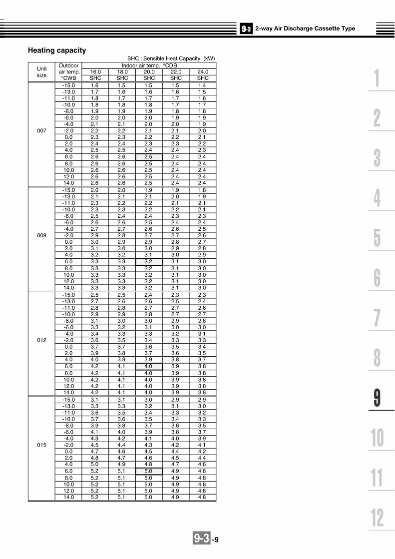
9-3 -9
Heating capacitySHC : Sensible Heat Capacity (kW)
UnitOutdoor Indoor air temp. °CDB
size air temp. 16.0 18.0 20.0 22.0 24.0
°CWB SHC SHC SHC SHC SHC-15.0 1.6 1.5 1.5 1.5 1.4-13.0 1.7 1.6 1.6 1.6 1.5-11.0 1.8 1.7 1.7 1.7 1.6-10.0 1.8 1.8 1.8 1.7 1.7-8.0 1.9 1.9 1.9 1.8 1.8-6.0 2.0 2.0 2.0 1.9 1.9-4.0 2.1 2.1 2.0 2.0 1.9
007 -2.0 2.2 2.2 2.1 2.1 2.00.0 2.3 2.3 2.2 2.2 2.12.0 2.4 2.4 2.3 2.3 2.24.0 2.5 2.5 2.4 2.4 2.36.0 2.6 2.6 2.5 2.4 2.48.0 2.6 2.6 2.5 2.4 2.410.0 2.6 2.6 2.5 2.4 2.412.0 2.6 2.6 2.5 2.4 2.414.0 2.6 2.6 2.5 2.4 2.4-15.0 2.0 2.0 1.9 1.9 1.8-13.0 2.1 2.1 2.1 2.0 1.9-11.0 2.3 2.2 2.2 2.1 2.1-10.0 2.3 2.3 2.2 2.2 2.1-8.0 2.5 2.4 2.4 2.3 2.3-6.0 2.6 2.6 2.5 2.4 2.4-4.0 2.7 2.7 2.6 2.6 2.5
009 -2.0 2.9 2.8 2.7 2.7 2.60.0 3.0 2.9 2.9 2.8 2.72.0 3.1 3.0 3.0 2.9 2.84.0 3.2 3.2 3.1 3.0 2.96.0 3.3 3.3 3.2 3.1 3.08.0 3.3 3.3 3.2 3.1 3.010.0 3.3 3.3 3.2 3.1 3.012.0 3.3 3.3 3.2 3.1 3.014.0 3.3 3.3 3.2 3.1 3.0-15.0 2.5 2.5 2.4 2.3 2.3-13.0 2.7 2.6 2.6 2.5 2.4-11.0 2.8 2.8 2.7 2.7 2.6-10.0 2.9 2.9 2.8 2.7 2.7-8.0 3.1 3.0 3.0 2.9 2.8-6.0 3.3 3.2 3.1 3.0 3.0-4.0 3.4 3.3 3.3 3.2 3.1
012 -2.0 3.6 3.5 3.4 3.3 3.30.0 3.7 3.7 3.6 3.5 3.42.0 3.9 3.8 3.7 3.6 3.54.0 4.0 3.9 3.9 3.8 3.76.0 4.2 4.1 4.0 3.9 3.88.0 4.2 4.1 4.0 3.9 3.810.0 4.2 4.1 4.0 3.9 3.812.0 4.2 4.1 4.0 3.9 3.814.0 4.2 4.1 4.0 3.9 3.8-15.0 3.1 3.1 3.0 2.9 2.9-13.0 3.3 3.3 3.2 3.1 3.0-11.0 3.6 3.5 3.4 3.3 3.2-10.0 3.7 3.6 3.5 3.4 3.3-8.0 3.9 3.8 3.7 3.6 3.5-6.0 4.1 4.0 3.9 3.8 3.7-4.0 4.3 4.2 4.1 4.0 3.9
015 -2.0 4.5 4.4 4.3 4.2 4.10.0 4.7 4.6 4.5 4.4 4.22.0 4.8 4.7 4.6 4.5 4.44.0 5.0 4.9 4.8 4.7 4.66.0 5.2 5.1 5.0 4.9 4.88.0 5.2 5.1 5.0 4.9 4.810.0 5.2 5.1 5.0 4.9 4.812.0 5.2 5.1 5.0 4.9 4.814.0 5.2 5.1 5.0 4.9 4.8

9-3 -10
Unit Outdoor Indoor air temp. °CDB
size air temp. 16.0 18.0 20.0 22.0 24.0
°CWB SHC SHC SHC SHC SHC-15.0 3.9 3.9 3.8 3.7 3.6-13.0 4.2 4.1 4.0 3.9 3.8-11.0 4.5 4.4 4.3 4.2 4.1-10.0 4.6 4.5 4.4 4.3 4.2-8.0 4.9 4.8 4.7 4.6 4.4-6.0 5.1 5.0 4.9 4.8 4.7-4.0 5.4 5.3 5.2 5.0 4.9
018 -2.0 5.6 5.5 5.4 5.3 5.10.0 5.9 5.8 5.6 5.5 5.32.0 6.1 6.0 5.9 5.7 5.64.0 6.3 6.2 6.1 5.9 5.86.0 6.6 6.4 6.3 6.1 6.08.0 6.6 6.4 6.3 6.1 6.010.0 6.6 6.4 6.3 6.1 6.012.0 6.6 6.4 6.3 6.1 6.014.0 6.6 6.4 6.3 6.1 6.0-15.0 5.0 4.9 4.8 4.7 4.6-13.0 5.3 5.2 5.1 5.0 4.9-11.0 5.7 5.6 5.5 5.3 5.2-10.0 5.8 5.7 5.6 5.5 5.3-8.0 6.2 6.1 5.9 5.8 5.6-6.0 6.5 6.4 6.2 6.1 5.9-4.0 6.8 6.7 6.6 6.4 6.2
024 -2.0 7.1 7.0 6.9 6.7 6.50.0 7.4 7.3 7.1 7.0 6.82.0 7.7 7.6 7.4 7.3 7.14.0 8.0 7.9 7.7 7.5 7.36.0 8.3 8.2 8.0 7.8 7.68.0 8.3 8.2 8.0 7.8 7.610.0 8.3 8.2 8.0 7.8 7.612.0 8.3 8.2 8.0 7.8 7.614.0 8.3 8.2 8.0 7.8 7.6-15.0 5.6 5.5 5.4 5.3 5.1-13.0 6.0 5.9 5.8 5.6 5.5-11.0 6.4 6.3 6.1 6.0 5.8-10.0 6.6 6.5 6.3 6.2 6.0-8.0 7.0 6.8 6.7 6.5 6.3-6.0 7.3 7.2 7.0 6.9 6.7-4.0 7.7 7.5 7.4 7.2 7.0
027 -2.0 8.0 7.9 7.7 7.5 7.30.0 8.4 8.2 8.0 7.8 7.62.0 8.7 8.5 8.4 8.2 7.94.0 9.0 8.9 8.7 8.5 8.36.0 9.4 9.2 9.0 8.8 8.68.0 9.4 9.2 9.0 8.8 8.610.0 9.4 9.2 9.0 8.8 8.612.0 9.4 9.2 9.0 8.8 8.614.0 9.4 9.2 9.0 8.8 8.6
Heating capacity (cont.)
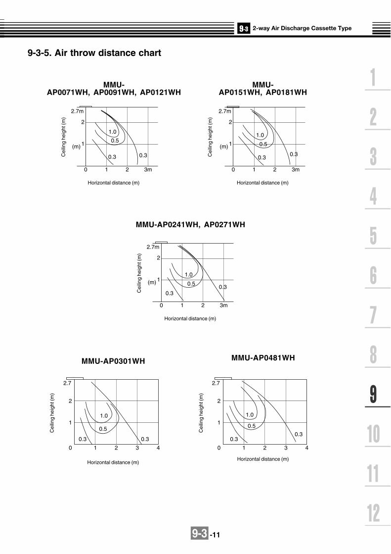
9-3 -11
2
0
(m)
1 2
0
1
2
2.7
1.0
0.5
0.30.3
1 2 3 4
3m
2.7m
1
1.0
0.5
0.3 0.3
2
0
(m)
1 2 3m
2.7m
1
1.0
0.50.5
0.30.30.3
2
0
(m)
1 2 3m
2.7m
11.0
0.5
0.30.30.3
0
1
2
2.7
1.0
0.5
0.30.3
1 2 3 4
9-3-5. Air throw distance chart
MMU-AP0071WH, AP0091WH, AP0121WH
Horizontal distance (m)
MMU-AP0151WH, AP0181WH
Horizontal distance (m)
MMU-AP0241WH, AP0271WH
Horizontal distance (m)
MMU-AP0301WH
Horizontal distance (m)
MMU-AP0481WH
Horizontal distance (m)
Cei
ling
heig
ht (m
)
Cei
ling
heig
ht (m
)
Cei
ling
heig
ht (m
)
Cei
ling
heig
ht (m
)
Cei
ling
heig
ht (m
)

9-3 -12
9-3-6. Sound characteristics (NC-Curve)
Microphone
MMU-AP0071WH, AP0091WH, AP0121WH
Oct
ave
band
sou
nd p
ress
ure
leve
l (dB
)
Octave band frequency (Hz)
standard sound pressure 0.0002 µbar
Audibility limitsof continuouswhite level
Fan Tap
Sound pressurelevel (dB(A))
H
34
M
32
L
30
Fan Tap
Sound pressurelevel (dB(A))
H
38
M
35
L
33
Fan Tap
Sound pressurelevel (dB(A))
H
35
M
33
L
30
MMU-AP0151WH, AP0181WH MMU-AP0241WH, AP0271WH
Oct
ave
band
sou
nd p
ress
ure
leve
l (dB
)
Oct
ave
band
sou
nd p
ress
ure
leve
l (dB
)
Octave band frequency (Hz) Octave band frequency (Hz)
Audibility limitsof continuouswhite level
Audibility limitsof continuouswhite level
standard sound pressure 0.0002 µbar standard sound pressure 0.0002 µbar
Sound level values shown are based on a measurement in a non resound room.

9-3 -13
NC-70
NC-60
NC-50
NC-40
NC-30
NC-20
HM
L
10
20
30
40
50
60
70
80
90
63 125 250 500 1000 2000 4000 8000
MMU-AP0301WH
Oct
ave
band
sou
nd p
ress
ure
leve
l (dB
)
Fan Tap
Sound pressurelevel (dB(A))
H
40
M
37
L
34
Audibility limitsof continuous white level
Octave band center frequency (Hz)
(Revised 07 Apr 2006)
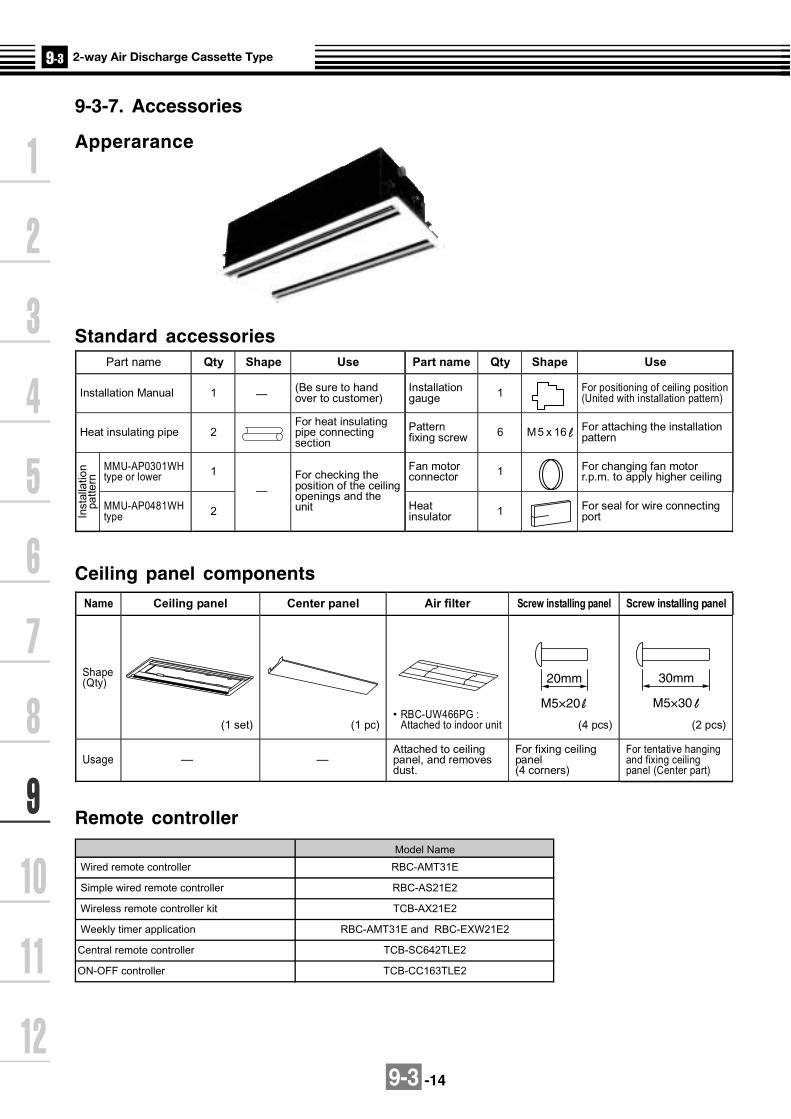
9-3 -14
9-3-7. Accessories
Apperarance
Standard accessories
Remote controller
Part name Qty Shape Use Part name Qty Shape Use
Installation Manual 1 (Be sure to hand over to customer)
Installation gauge 1 For positioning of ceiling position
(United with installation pattern)
Heat insulating pipe 2 For heat insulating pipe connecting section
Pattern fixing screw 6 M5 x 16 For attaching the installation
pattern
MMU-AP0301WH type or lower 1 Fan motor
connector 1 For changing fan motor r.p.m. to apply higher ceiling
Inst
alla
tion
patte
rn
MMU-AP0481WH type 2
—
—
For checking the position of the ceiling openings and the unit Heat
insulator 1 For seal for wire connecting port
Ceiling panel componentsName Ceiling panel Center panel Air filter Screw installing panel Screw installing panel
Shape (Qty)
(1 set) (1 pc) • RBC-UW466PG :
Attached to indoor unit (4 pcs) (2 pcs)
Usage — — Attached to ceiling panel, and removes dust.
For fixing ceiling panel (4 corners)
For tentative hanging and fixing ceiling panel (Center part)
20mm
M5×20
30mm
M5×30
Central remote controller TCB-SC642TLE2
ON-OFF controller TCB-CC163TLE2
Weekly timer application
Model Name
RBC-AMT31E
RBC-AS21E2
TCB-AX21E2
RBC-AMT31E and RBC-EXW21E2
Wired remote controller
Simple wired remote controller
Wireless remote controller kit

9-3 -15
Optional accessories
Name Model name Note
Required accessoryRBC-UW136PG
RBC-UW266PGCeiling panel
Ceiling panel
RBC-UW136PGRBC-UW266PGRBC-UW466PG

9-4 -1
9-4-1. Specifications 50Hz
Note 1 : The cooling capacities and electrical characteristics are measured under the conditions specified by JIS B 8615 based on thereference piping. The reference piping consists of 5 m of main piping and 2.5 m of branch piping connected with 0 meter height.
Note 2 : The sound level are measured in an anechoic chamber in accordance with JIS B8616. Normally, the values measured in theactual operating environment become larger than the indicated values due to the effects of external sound.
Note : Rated conditions Cooling : Indoor air temperature 27oC DB/19oC WB, Outdoor air temperature 35oC DBHeating : Indoor air temperature 20oC DB, Outdoor air temperature 7oC DB/6oC WB
Model name MMU-
Cooling/Heating capacity (Note 1) (kW)
Electricalcharacteris-t ics(Note 2)
Power supply
Running current (A)
Power consumption (kW)
Power factor (%)
Starting current (A)
Main unit
AppearanceCeilingpanel
Model
Panel color
Outerdimension
Main unit
Ceilingpanel
Height (mm)
Width (mm)
Depth (mm)
Height (mm)
Width (mm)
Depth (mm)
Total weighMain unit (kg)
Ceiling panel (kg)
Heat exchanger
Soundproof/Heat-insulating material
Fan unit
Fan
Standard air flow(High/Mid/Low)
(m3/h)
Motor (W)
Controller
Air filter
Connectingpipe
Gas side (mm)
Liquid side (mm)
Drain port (Nominal dia. mm)
Sound pressure level (Note 2)(High/Mid/Low) (dB(A))
AP0071YH
2.2/2.5
1 phase 50Hz 230V (220-240V) (Separate power supply for indoor units is required.)
AP0091YH
2.8/3.2
AP0121YH
3.6/4.0
AP0152SH
4.5/5.0
AP0182SH
5.6/6.3
AP0242SH
7.1/8.0
0.24
0.053
95
0.6
Heat-insulating material attached Zinc hot dipping steel plate
W : Silky shade (1Y8.5/0.5)
RBC-UY135PG
235
850
400
18
1,050
470
22
3.5
Finned tube
Centrifugal fan
540/480/420
22
Remote controller
Standard filter (Long life filter)
O/ 9.5
O/ 6.4
25 (Polyvinyl chloride tube:External dia.32 Internal dia.25)
42/39/34
0.34
0.042
_
0.53
0.37
0.046
_
0.54
0.62
0.075
_
0.80
RBC-US21PGE
Moon white (Munsel 2.5GY9.0/0.5)
200
1,000
710
20
1,230
800
21 22
5.5
Non-flammable insulation Polyethylene foam + Expanded polystyrene
750/690/630 780/720/660 1,140/960/810
30
O/ 9.5
O/ 12.7 O/ 15.9
37/35/32 38/36/34 45/41/37
PMV Kit Available
Specifications (50Hz)

9-4 -2
60Hz
Note 1 : The cooling capacities and electrical characteristics are measured under the conditions specified by JIS B 8615 based on thereference piping. The reference piping consists of 5 m of main piping and 2.5 m of branch piping connected with 0 meter height.
Note 2 : The sound level are measured in an anechoic chamber in accordance with JIS B8616. Normally, the values measured in theactual operating environment become larger than the indicated values due to the effects of external sound.
Note : Rated conditions Cooling : Indoor air temperature 27oC DB/19oC WB, Outdoor air temperature 35oC DBHeating : Indoor air temperature 20oC DB, Outdoor air temperature 7oC DB/6oC WB
Model name MMU-
Cooling/Heating capacity (Note 1) (kW)
Electricalcharacteris-t ics(Note 2)
Power supply
Running current (A)
Power consumption (kW)
Power factor (%)
Starting current (A)
Main unit
AppearanceCeilingpanel
Model
Panel color
Outerdimension
Main unit
Ceilingpanel
Height (mm)
Width (mm)
Depth (mm)
Height (mm)
Width (mm)
Depth (mm)
Total weighMain unit (kg)
Ceiling panel (kg)
Heat exchanger
Soundproof/Heat-insulating material
Fan unit
Fan
Standard air flow(High/Mid/Low)
(m3/h)
Motor (W)
Controller
Air filter
AP0071YH
2.2/2.5
1 phase 60Hz 220V (Separate power supply for indoor units is required.)
AP0091YH
2.8/3.2
AP0121YH
3.6/4.0
AP0152SH
4.5/5.0
AP0182SH
5.6/6.3
AP0242SH
7.1/8.0
0.26
0.056
98
0.60
Heat-insulating material attached Zinc hot dipping steel plate
W : Silky shade (1Y8.5/0.5)
RBC-UY135PG
235
850
400
18
1,050
470
22
3.5
Finned tube
Centrifugal fan
540/480/420
22
Remote controller
Standard filter (Long life filter)
0.35
0.041
_
0.53
0.39
0.045
_
0.54
0.62
0.073
_
0.80
RBC-US21PGE
Moon white (Munsel 2.5GY9.0/0.5)
200
1,000
710
20
1,230
800
21 22
5.5
Non-flammable insulation Polyethylene foam + Expanded polystyrene
750/690/630 780/720/660 1,140/960/810
30
Specifications (60Hz)
Connectingpipe
Gas side (mm)
Liquid side (mm)
Drain port (Nominal dia. mm)
Sound pressure level (Note 2)(High/Mid/Low) (dB(A))
O/ 9.5
O/ 6.4
25 (Polyvinyl chloride tube:External dia.32 Internal dia.25)
42/39/34
O/ 9.5
O/ 12.7 O/ 15.9
37/35/32 38/36/34 45/41/37
PMV Kit Available

9-4 -3
16
4 2.7
120
120
Panel external dimension 1050
Ceiling open dimension 1010
Pan
el e
xter
nal
dim
ensi
on47
0
Cei
ling
open
dim
ensi
on43
020
20
Center of panelDrain pipe connecting port(VP25)
Power supply connecting port
Hanging bolt4-M10 procured locally
Supportmetal
Ceiling panelProcured locally
Bottom face of ceilingAir discharge portDischarge louver
Refrigerant pipe connecting port(Gas side) Ø9.5
Refrigerant pipe connecting port(Liquid side) Ø6.4
Panel mounting hole5 positions
Air suction port
100 or more 100 or more 200 or more
Bor
mor
e
Space required for installation and servicing
Note: All dimensions are in mm.
Wired remote controller RBC-AMT31E
Simple wired remote controller RBC-AS21E2
Wireless remote controller kit TCB-AX21E2
Weekly timer application RBC-AMT31E and RBC-EXW21E2
DimensionsModel MMU-
AP0071YH,AP0091YH, AP0121YH
A
235
B
245
C
200
MMU-AP0071YH, AP0091YH, AP0121YH
9-4-2. Dimension

9-4 -4
Cable inlet (Knockout hole)
Drain pipe connecting port(Be sure to connect the attached flexible hose.)
248
20 94
154
5620
20
7673
.4
135
220
233
122
200
20
2.7
120
93
475
Han
ging
bol
t pitc
h
760
Cei
ling
open
ing
size
710
Uni
t ext
erna
l siz
e
800
Pan
el e
xter
nal s
ize
1060 Hanging bolt pitch
Refrigerant pipe connecting port Gas side B
Refrigerant pipe connecting port Liquid side A
Hanging bolt M10 or W3/8 (Local supply)
1190 Ceiling opening size
1230 Panel external size
1000 Unit external size
Lower surface of ceiling Ceiling panel (Sold separately) For front air discharge unit (Sold separately) knockout hole
100 43
6080
216
72
Cable inlet
252
C/L
C/L
20
706
4
12016
112Fresh air inlet (Ø92 knockout hole)
Ø112 (4-tapping screw under-hole)
Model name MMU-
AP015, AP018 type
AP024 type
A B
O/ 6.4 O/ 12.7
O/ 9.5 O/ 15.9
Wired remote controller RBC-AMT31E
Simple wired remote controller RBC-AS21E2
Wireless remote controller kit TCB-AX21E2
Weekly timer application RBC-AMT31E and RBC-EXW21E2
MMU-AP0152SH, AP0182SH, AP0242SH

9-4-5
CN104(YEL)
CN102(RED)
CN101(BLK)
5 4 3 2 15 4 3 2 1
9 8 7 69 8 7 6
FANCN083(WHI)
DP(BLU)CN068
DM
CN304(GRY)
Heater
CN301(BLK)
CN066(WHI)
WHI
RED
BLU
BLUBLU
CN067(BLK)
12
12
TA
TCJ
12
12
12
CN100(BRW)
12
12
33
CN080(GRN) PNL
EXCT
12
CN073(RED)
12
FilterCN070(WHI)
CN081(BLK)
CN060(WHI)
Option
CN032(WHI)
CN075(WHI)
CN074(WHI)
TR
12
12345
12
3
TC1
1 2 3 4 5 6
CN061(YEL)
Fan drive
1 2 3 4 5 61 2 3 4 5 61 2 3
1 2 31 3
1 21 2
1 2 31 2 3
1 2 31 2 3
1 2 31 2 3
4 5 6
CN050(WHI)
CN041(BLU)
CN040(BLU)
1 21 2
CN044(BRW)
CN01(WHI)
CN02(BLU)
Network adaptor(Option)
1 21 2 3 4 5
1 21 2
1 12 2
2 12
33 1
CN03(RED)
MCC-1401
RY004123
12
RY002
RY006
RY007
RY005
1 2
BA YXS(N)R(L) U2
1 2Remote controller
CN1(WHI)
Power supplySingle phase
220-240V 50Hz 220V 60Hz
Indoor unitEarth screw
Outdoorunit
BLU
BLU
RE
D
WH
I
BLK
BLK
U1
U2U1
Power supplycircuit
Network adaptorP.C. board
LM(GRN)CN033
LM
1 2 31 2 3
FS(RED)CN030
PMV(BLU)CN082
FS
1 2 31 2 3
1 2 31 2 3
4 5 64 5 6
6 4 36 4 3
1 2 51 2 5
RY001
AI-NETcentral control terminal
TR
FuseT5.0A
123
123
CN309(YEL)
AC IN
123
123
2 12 1
2 12 1
PMV12
12
34
34
56
56
FM
YE
L
BLU
OR
N
BLK
RE
D
H M L UL
RC
Closed end connector
1 2 3 4 5 61 2 3 4 5 6
1 2 3 4 5 61 2 3 4 5 6
CN01(WHI)
CN02(YEL)
Sub P.C. boardMCC-1520
Line Filter
Flow selector unit earth
screw
9-4-3. Wirin
g d
iagram
1-way A
ir Disch
arge C
assette Type (C
om
pact typ
e)M
od
el: MM
U-A
P0071Y
H, A
P0091Y
H, A
P0121Y
H
1. indicates the terminal block, the letter insideindicates the terminal number.
2. A dotted line and broken line indicate the wiring on site.
3. indicates the control P.C. board.
Symbol
FM
RC
TR
LM
TA
TC1,TCJ
RY001
RY002
RY004
RY005~007
FS
D M
PMV
Parts name
Fan motor
Running capacitor
Power transformer
Louver motor
Indoor temp sensor
Temp sensor
Flap motor control relay
Drain pump control relay
Heater control relay
Fan motor control relay
Float switch
Drain pump motor
Pulse Motor Valve
Colorindication
RED : REDWHI : WHITEYEL : YELLOWBLU : BLUEBLK : BLACKGRY : GRAYPNK : PINKORN :ORANGEBRN : BROWNGRN : GREEN
Indoor control P.C. board

9-4 -6
1-way (2 series) Air Discharge Cassette Type (MMU-AP***SH)
on s
ide

9-4 -7
TC : Total Capacity (kW) SHC : Sensible Heat Capacity (kW)Indoor air temp.
Unit Outdoor 16.0°CWB 18.0°CWB 19.0°CWB 20.0°CWB 22.0°CWB 24.0°CWBsize air temp. 23°CDB 26°CDB 27°CDB 28°CDB 30°CDB 32°CDB
°CDB TC SHC TC SHC TC SHC TC SHC TC SHC TC SHC10.0 2.0 1.7 2.1 1.8 2.2 1.8 2.3 1.8 2.4 1.8 2.5 1.712.0 2.0 1.7 2.1 1.8 2.2 1.8 2.3 1.8 2.4 1.8 2.5 1.714.0 2.0 1.7 2.1 1.8 2.2 1.8 2.3 1.8 2.4 1.8 2.5 1.716.0 2.0 1.7 2.1 1.8 2.2 1.8 2.3 1.8 2.4 1.8 2.5 1.718.0 2.0 1.7 2.1 1.8 2.2 1.8 2.3 1.8 2.4 1.8 2.5 1.720.0 2.0 1.7 2.1 1.8 2.2 1.8 2.3 1.8 2.4 1.8 2.5 1.721.0 2.0 1.7 2.1 1.8 2.2 1.8 2.3 1.8 2.4 1.8 2.5 1.7
007 23.0 2.0 1.7 2.1 1.8 2.2 1.8 2.3 1.8 2.4 1.8 2.5 1.725.0 2.0 1.7 2.1 1.8 2.2 1.8 2.3 1.8 2.4 1.8 2.5 1.727.0 2.0 1.7 2.1 1.8 2.2 1.8 2.3 1.8 2.4 1.8 2.5 1.729.0 2.0 1.7 2.1 1.8 2.2 1.8 2.3 1.8 2.4 1.8 2.5 1.731.0 2.0 1.7 2.1 1.8 2.2 1.8 2.3 1.8 2.4 1.8 2.5 1.733.0 2.0 1.7 2.1 1.8 2.2 1.8 2.3 1.8 2.4 1.8 2.5 1.735.0 2.0 1.7 2.1 1.8 2.2 1.8 2.3 1.8 2.4 1.8 2.5 1.737.0 2.0 1.7 2.1 1.8 2.2 1.8 2.2 1.8 2.4 1.7 2.5 1.739.0 1.9 1.6 2.0 1.7 2.1 1.7 2.2 1.7 2.3 1.7 2.4 1.610.0 2.5 2.1 2.7 2.2 2.8 2.2 2.9 2.2 3.1 2.2 3.2 2.112.0 2.5 2.1 2.7 2.2 2.8 2.2 2.9 2.2 3.1 2.2 3.2 2.114.0 2.5 2.1 2.7 2.2 2.8 2.2 2.9 2.2 3.1 2.2 3.2 2.116.0 2.5 2.1 2.7 2.2 2.8 2.2 2.9 2.2 3.1 2.2 3.2 2.118.0 2.5 2.1 2.7 2.2 2.8 2.2 2.9 2.2 3.1 2.2 3.2 2.120.0 2.5 2.1 2.7 2.2 2.8 2.2 2.9 2.2 3.1 2.2 3.2 2.121.0 2.5 2.1 2.7 2.2 2.8 2.2 2.9 2.2 3.1 2.2 3.2 2.1
009 23.0 2.5 2.1 2.7 2.2 2.8 2.2 2.9 2.2 3.1 2.2 3.2 2.125.0 2.5 2.1 2.7 2.2 2.8 2.2 2.9 2.2 3.1 2.2 3.2 2.127.0 2.5 2.1 2.7 2.2 2.8 2.2 2.9 2.2 3.1 2.2 3.2 2.129.0 2.5 2.1 2.7 2.2 2.8 2.2 2.9 2.2 3.1 2.2 3.2 2.131.0 2.5 2.1 2.7 2.2 2.8 2.2 2.9 2.2 3.1 2.2 3.2 2.133.0 2.5 2.1 2.7 2.2 2.8 2.2 2.9 2.2 3.1 2.2 3.2 2.135.0 2.5 2.1 2.7 2.2 2.8 2.2 2.9 2.2 3.1 2.2 3.2 2.137.0 2.5 2.0 2.7 2.2 2.7 2.2 2.8 2.2 3.0 2.1 3.1 2.139.0 2.4 2.0 2.6 2.1 2.7 2.1 2.8 2.1 2.9 2.1 3.1 2.010.0 3.3 2.5 3.5 2.7 3.6 2.7 3.7 2.7 3.9 2.7 4.1 2.612.0 3.3 2.5 3.5 2.7 3.6 2.7 3.7 2.7 3.9 2.7 4.1 2.614.0 3.3 2.5 3.5 2.7 3.6 2.7 3.7 2.7 3.9 2.7 4.1 2.616.0 3.3 2.5 3.5 2.7 3.6 2.7 3.7 2.7 3.9 2.7 4.1 2.618.0 3.3 2.5 3.5 2.7 3.6 2.7 3.7 2.7 3.9 2.7 4.1 2.620.0 3.3 2.5 3.5 2.7 3.6 2.7 3.7 2.7 3.9 2.7 4.1 2.621.0 3.3 2.5 3.5 2.7 3.6 2.7 3.7 2.7 3.9 2.7 4.1 2.6
012 23.0 3.3 2.5 3.5 2.7 3.6 2.7 3.7 2.7 3.9 2.7 4.1 2.625.0 3.3 2.5 3.5 2.7 3.6 2.7 3.7 2.7 3.9 2.7 4.1 2.627.0 3.3 2.5 3.5 2.7 3.6 2.7 3.7 2.7 3.9 2.7 4.1 2.629.0 3.3 2.5 3.5 2.7 3.6 2.7 3.7 2.7 3.9 2.7 4.1 2.631.0 3.3 2.5 3.5 2.7 3.6 2.7 3.7 2.7 3.9 2.7 4.1 2.633.0 3.3 2.5 3.5 2.7 3.6 2.7 3.7 2.7 3.9 2.7 4.1 2.635.0 3.3 2.5 3.5 2.7 3.6 2.7 3.7 2.7 3.9 2.7 4.1 2.637.0 3.2 2.5 3.4 2.7 3.5 2.6 3.6 2.6 3.8 2.6 4.0 2.639.0 3.1 2.4 3.4 2.5 3.5 2.5 3.6 2.5 3.8 2.5 3.9 2.5
9-4-4. Sensible capacity table(MMU-AP***YH, MMU-AP***SH)
Cooling capacity

9-4 -8
Cooling capacity (cont.)
Indoor air temp.Unit Outdoor 16.0°CWB 18.0°CWB 19.0°CWB 20.0°CWB 22.0°CWB 24.0°CWBsize air temp. 23°CDB 26°CDB 27°CDB 28°CDB 30°CDB 32°CDB
°CDB TC SHC TC SHC TC SHC TC SHC TC SHC TC SHC10.0 4.1 3.0 4.4 3.2 4.5 3.2 4.6 3.2 4.9 3.2 5.1 3.112.0 4.1 3.0 4.4 3.2 4.5 3.2 4.6 3.2 4.9 3.2 5.1 3.114.0 4.1 3.0 4.4 3.2 4.5 3.2 4.6 3.2 4.9 3.2 5.1 3.116.0 4.1 3.0 4.4 3.2 4.5 3.2 4.6 3.2 4.9 3.2 5.1 3.118.0 4.1 3.0 4.4 3.2 4.5 3.2 4.6 3.2 4.9 3.2 5.1 3.120.0 4.1 3.0 4.4 3.2 4.5 3.2 4.6 3.2 4.9 3.2 5.1 3.121.0 4.1 3.0 4.4 3.2 4.5 3.2 4.6 3.2 4.9 3.2 5.1 3.1
015 23.0 4.1 3.0 4.4 3.2 4.5 3.2 4.6 3.2 4.9 3.2 5.1 3.125.0 4.1 3.0 4.4 3.2 4.5 3.2 4.6 3.2 4.9 3.2 5.1 3.127.0 4.1 3.0 4.4 3.2 4.5 3.2 4.6 3.2 4.9 3.2 5.1 3.129.0 4.1 3.0 4.4 3.2 4.5 3.2 4.6 3.2 4.9 3.2 5.1 3.131.0 4.1 3.0 4.4 3.2 4.5 3.2 4.6 3.2 4.9 3.2 5.1 3.133.0 4.1 3.0 4.4 3.2 4.5 3.2 4.6 3.2 4.9 3.2 5.1 3.135.0 4.1 3.0 4.4 3.2 4.5 3.2 4.6 3.2 4.9 3.2 5.1 3.137.0 4.0 3.0 4.3 3.1 4.4 3.1 4.5 3.1 4.8 3.1 5.0 3.039.0 3.9 2.8 4.2 3.0 4.3 3.0 4.4 3.0 4.7 3.0 4.9 2.910.0 5.1 3.7 5.4 3.9 5.6 3.9 5.8 3.9 6.1 3.9 6.4 3.812.0 5.1 3.7 5.4 3.9 5.6 3.9 5.8 3.9 6.1 3.9 6.4 3.814.0 5.1 3.7 5.4 3.9 5.6 3.9 5.8 3.9 6.1 3.9 6.4 3.816.0 5.1 3.7 5.4 3.9 5.6 3.9 5.8 3.9 6.1 3.9 6.4 3.818.0 5.1 3.7 5.4 3.9 5.6 3.9 5.8 3.9 6.1 3.9 6.4 3.820.0 5.1 3.7 5.4 3.9 5.6 3.9 5.8 3.9 6.1 3.9 6.4 3.821.0 5.1 3.7 5.4 3.9 5.6 3.9 5.8 3.9 6.1 3.9 6.4 3.8
018 23.0 5.1 3.7 5.4 3.9 5.6 3.9 5.8 3.9 6.1 3.9 6.4 3.825.0 5.1 3.7 5.4 3.9 5.6 3.9 5.8 3.9 6.1 3.9 6.4 3.827.0 5.1 3.7 5.4 3.9 5.6 3.9 5.8 3.9 6.1 3.9 6.4 3.829.0 5.1 3.7 5.4 3.9 5.6 3.9 5.8 3.9 6.1 3.9 6.4 3.831.0 5.1 3.7 5.4 3.9 5.6 3.9 5.8 3.9 6.1 3.9 6.4 3.833.0 5.1 3.7 5.4 3.9 5.6 3.9 5.8 3.9 6.1 3.9 6.4 3.835.0 5.1 3.7 5.4 3.9 5.6 3.9 5.8 3.9 6.1 3.9 6.4 3.837.0 5.0 3.6 5.3 3.8 5.5 3.8 5.7 3.8 6.0 3.8 6.3 3.739.0 4.9 3.5 5.2 3.7 5.4 3.7 5.5 3.7 5.9 3.6 6.1 3.610.0 6.4 4.7 6.9 5.0 7.1 5.0 7.3 5.0 7.7 5.0 8.1 4.812.0 6.4 4.7 6.9 5.0 7.1 5.0 7.3 5.0 7.7 5.0 8.1 4.814.0 6.4 4.7 6.9 5.0 7.1 5.0 7.3 5.0 7.7 5.0 8.1 4.816.0 6.4 4.7 6.9 5.0 7.1 5.0 7.3 5.0 7.7 5.0 8.1 4.818.0 6.4 4.7 6.9 5.0 7.1 5.0 7.3 5.0 7.7 5.0 8.1 4.820.0 6.4 4.7 6.9 5.0 7.1 5.0 7.3 5.0 7.7 5.0 8.1 4.821.0 6.4 4.7 6.9 5.0 7.1 5.0 7.3 5.0 7.7 5.0 8.1 4.8
024 23.0 6.4 4.7 6.9 5.0 7.1 5.0 7.3 5.0 7.7 5.0 8.1 4.825.0 6.4 4.7 6.9 5.0 7.1 5.0 7.3 5.0 7.7 5.0 8.1 4.827.0 6.4 4.7 6.9 5.0 7.1 5.0 7.3 5.0 7.7 5.0 8.1 4.829.0 6.4 4.7 6.9 5.0 7.1 5.0 7.3 5.0 7.7 5.0 8.1 4.831.0 6.4 4.7 6.9 5.0 7.1 5.0 7.3 5.0 7.7 5.0 8.1 4.833.0 6.4 4.7 6.9 5.0 7.1 5.0 7.3 5.0 7.7 5.0 8.1 4.835.0 6.4 4.7 6.9 5.0 7.1 5.0 7.3 5.0 7.7 5.0 8.1 4.837.0 6.3 4.6 6.7 4.9 7.0 4.9 7.2 4.9 7.6 4.9 7.9 4.739.0 6.2 4.4 6.6 4.7 6.8 4.7 7.0 4.7 7.4 4.7 7.8 4.6

9-4 -9
Heating capacitySHC : Sensible Heat Capacity (kW)
Unit Outdoor Indoor air temp. °CDB
size air temp. 16.0 18.0 20.0 22.0 24.0
°CWB SHC SHC SHC SHC SHC-15.0 1.6 1.5 1.5 1.5 1.4-13.0 1.7 1.6 1.6 1.6 1.5-11.0 1.8 1.7 1.7 1.7 1.6-10.0 1.8 1.8 1.8 1.7 1.7-8.0 1.9 1.9 1.9 1.8 1.8-6.0 2.0 2.0 2.0 1.9 1.9-4.0 2.1 2.1 2.0 2.0 1.9
007 -2.0 2.2 2.2 2.1 2.1 2.00.0 2.3 2.3 2.2 2.2 2.12.0 2.4 2.4 2.3 2.3 2.24.0 2.5 2.5 2.4 2.4 2.36.0 2.6 2.6 2.5 2.4 2.48.0 2.6 2.6 2.5 2.4 2.410.0 2.6 2.6 2.5 2.4 2.412.0 2.6 2.6 2.5 2.4 2.414.0 2.6 2.6 2.5 2.4 2.4-15.0 2.0 2.0 1.9 1.9 1.8-13.0 2.1 2.1 2.1 2.0 1.9-11.0 2.3 2.2 2.2 2.1 2.1-10.0 2.3 2.3 2.2 2.2 2.1-8.0 2.5 2.4 2.4 2.3 2.3-6.0 2.6 2.6 2.5 2.4 2.4-4.0 2.7 2.7 2.6 2.6 2.5
009 -2.0 2.9 2.8 2.7 2.7 2.60.0 3.0 2.9 2.9 2.8 2.72.0 3.1 3.0 3.0 2.9 2.84.0 3.2 3.2 3.1 3.0 2.96.0 3.3 3.3 3.2 3.1 3.08.0 3.3 3.3 3.2 3.1 3.010.0 3.3 3.3 3.2 3.1 3.012.0 3.3 3.3 3.2 3.1 3.014.0 3.3 3.3 3.2 3.1 3.0-15.0 2.5 2.5 2.4 2.3 2.3-13.0 2.7 2.6 2.6 2.5 2.4-11.0 2.8 2.8 2.7 2.7 2.6-10.0 2.9 2.9 2.8 2.7 2.7-8.0 3.1 3.0 3.0 2.9 2.8-6.0 3.3 3.2 3.1 3.0 3.0-4.0 3.4 3.3 3.3 3.2 3.1
012 -2.0 3.6 3.5 3.4 3.3 3.30.0 3.7 3.7 3.6 3.5 3.42.0 3.9 3.8 3.7 3.6 3.54.0 4.0 3.9 3.9 3.8 3.76.0 4.2 4.1 4.0 3.9 3.88.0 4.2 4.1 4.0 3.9 3.810.0 4.2 4.1 4.0 3.9 3.812.0 4.2 4.1 4.0 3.9 3.814.0 4.2 4.1 4.0 3.9 3.8

9-4 -10
Heating capacity (cont.)
UnitOutdoor Indoor air temp. °CDB
size air temp. 16.0 18.0 20.0 22.0 24.0
°CWB SHC SHC SHC SHC SHC-15.0 3.1 3.1 3.0 2.9 2.9-13.0 3.3 3.3 3.2 3.1 3.0-11.0 3.6 3.5 3.4 3.3 3.2-10.0 3.7 3.6 3.5 3.4 3.3-8.0 3.9 3.8 3.7 3.6 3.5-6.0 4.1 4.0 3.9 3.8 3.7-4.0 4.3 4.2 4.1 4.0 3.9
015 -2.0 4.5 4.4 4.3 4.2 4.10.0 4.7 4.6 4.5 4.4 4.22.0 4.8 4.7 4.6 4.5 4.44.0 5.0 4.9 4.8 4.7 4.66.0 5.2 5.1 5.0 4.9 4.88.0 5.2 5.1 5.0 4.9 4.810.0 5.2 5.1 5.0 4.9 4.812.0 5.2 5.1 5.0 4.9 4.814.0 5.2 5.1 5.0 4.9 4.8-15.0 3.9 3.9 3.8 3.7 3.6-13.0 4.2 4.1 4.0 3.9 3.8-11.0 4.5 4.4 4.3 4.2 4.1-10.0 4.6 4.5 4.4 4.3 4.2-8.0 4.9 4.8 4.7 4.6 4.4-6.0 5.1 5.0 4.9 4.8 4.7-4.0 5.4 5.3 5.2 5.0 4.9
018 -2.0 5.6 5.5 5.4 5.3 5.10.0 5.9 5.8 5.6 5.5 5.32.0 6.1 6.0 5.9 5.7 5.64.0 6.3 6.2 6.1 5.9 5.86.0 6.6 6.4 6.3 6.1 6.08.0 6.6 6.4 6.3 6.1 6.010.0 6.6 6.4 6.3 6.1 6.012.0 6.6 6.4 6.3 6.1 6.014.0 6.6 6.4 6.3 6.1 6.0-15.0 5.0 4.9 4.8 4.7 4.6-13.0 5.3 5.2 5.1 5.0 4.9-11.0 5.7 5.6 5.5 5.3 5.2-10.0 5.8 5.7 5.6 5.5 5.3-8.0 6.2 6.1 5.9 5.8 5.6-6.0 6.5 6.4 6.2 6.1 5.9-4.0 6.8 6.7 6.6 6.4 6.2
024 -2.0 7.1 7.0 6.9 6.7 6.50.0 7.4 7.3 7.1 7.0 6.82.0 7.7 7.6 7.4 7.3 7.14.0 8.0 7.9 7.7 7.5 7.36.0 8.3 8.2 8.0 7.8 7.68.0 8.3 8.2 8.0 7.8 7.610.0 8.3 8.2 8.0 7.8 7.612.0 8.3 8.2 8.0 7.8 7.614.0 8.3 8.2 8.0 7.8 7.6
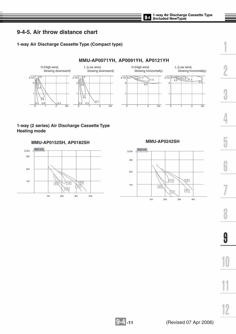
9-4 -11
9-4-5. Air throw distance chart
1-way Air Discharge Cassette Type (Compact type)
2.7m
2
0 1 2 3m0.6
0.9
0.4 0.4
2.3
5.0
1
2.7m
2
0 1 2 3m
1.71.5
0.4
4.5
1
2.7m
2
0 1 2 3m0.3
0.5
0.20.2
2.5
4.0
1
2.7m
2
0 1 2 3m
1.5 1.10.3
3.00.3
1
MMU-AP0071YH, AP0091YH, AP0121YHH (High wind, blowing downward)
L (Low wind, blowing downward)
L (Low wind, blowing horizontally)
H (High wind, blowing horizontally)
1-way (2 series) Air Discharge Cassette TypeHeating mode
MMU-AP0242SH
1.0
0.50.5
0.3 0.3
Main unit3.5m
3m
2m
1m
1m 2m 3m 4m
Main unit
1.0
0.50.5
0.3
0.3
3.5m
3m
2m
1m
1m 2m 3m 4m
MMU-AP0152SH, AP0182SH
(Revised 07 Apr 2006)

9-4 -12
9-4-6. Sound characteristics (NC-Curve)
1-way Air Discharge Cassette Type (Compact type)
MMU-AP0071YH, MMU-AP0091YH, MMU-AP0121YH
Fan tapSound pressure
level (dB(A))3442 39
10
20
30
40
50
60
70
80
90
63 125 250 500 1000 2000 4000 8000Octave band center frequency (Hz)
Oct
ave
band
sou
nd p
ress
ure
leve
l (dB
)
NC-60
NC-50
NC-40
NC- 30
NC-20Approximate threshold ofhearing for continuous noise
L
HM
NC-70
LH M
Microphone
(Revised 19 May 2006)

9-4 -13
1-way (2 series) Air Discharge Cassette Type
MMU-AP0152SH MMU-AP0242SH
MMU-AP0182SH
10
20
30
40
50
60
70
80
90
63 125 250 500 1000 2000 4000 8000
Octave band center frequency (Hz)
Oct
ave
band
sou
nd p
ress
ure
leve
l (dB
)
L
H M
NC-60
NC-50
NC-40
NC-20
NC-70
NC-30
Approximate threshold ofhearing for continuous noise
10
20
30
40
50
60
70
80
90
63 125 250 500 1000 2000 4000 8000
Octave band center frequency (Hz)
Oct
ave
band
sou
nd p
ress
ure
leve
l (dB
)M
L
H
NC-60
NC-50
NC-40
NC-20
NC-70
NC-30
Approximate threshold ofhearing for continuous noise
10
20
30
40
50
60
70
80
90
63 125 250 500 1000 2000 4000 8000
Octave band center frequency (Hz)
Oct
ave
band
sou
nd p
ress
ure
leve
l (dB
)
L
H M
NC-60
NC-50
NC-40
NC-20
NC-70
NC-30
Approximate threshold ofhearing for continuous noise
Center1.5m
Microphone
Fan tapSound pressure
level (dB(A))
H M L
37 35 32
Fan tapSound pressure
level (dB(A))
H M L
45 41 37
Fan tapSound pressure
level (dB(A))
H M L
38 36 34

9-4 -14
9-4-7. Accessories1-way (2 series) Air Discharge Cassette Type
Apperarance
Standard accessories
—
—
Qty Shape
Installation Manual
Heat insulating pipe
Installation gauge
Installation pattern
Part name
1
2
—
1
(Be sure to hand over to customer)
For heat insulating of pipe connecting section
For positioning of ceiling position
For confirmation of ceiling opening and main unit position
Use
Celling panel components
Qty Part name
RBC-US135PG, 165PG, 265PG type Use
Ceiling panel 1 —
Intake grille 3 —
Air filter 1 Located in the intake grille and removes dust and dirt from the air.
Panel installation screw (M5 x 20) 7 For securing the ceiling panel
Screw head insulation 1 set Prevents condensation from forming on screw heads
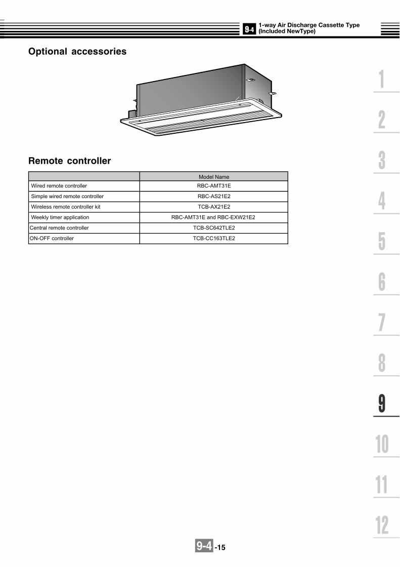
9-4 -15
Optional accessories
Remote controller
Wireless remote controller kit
Central remote controller
ON-OFF controller
TCB-SC642TLE2
TCB-CC163TLE2
Weekly timer application
Model Name
RBC-AMT31E
RBC-AS21E2
TCB-AX21E2
RBC-AMT31E and RBC-EXW21E2
Wired remote controller
Simple wired remote controller

9-4 -16
1-way (2 series) Air Discharge Cassette Type
Apperarance
Standard accessories
Qty Shape Use
M5 x 16
Installation Manual This manual
Installation pattern
Installation gauge
Pattern fixing screw
Heat insulating pipe
Part name
Washer
Heat insulator
Heat insulator
Flexible hose
Hose band
1
1
1
4
2
8
1
1
1
1
For hanging-down of unit
For connecting drain pipe
For adjustment of drain pipe centering
For insulating drain connecting section
For sealing of pipe connection port (With slit)
(Be sure to hand over to customer)
For check of ceiling opening and unit position
For check of ceiling opening and unit position(Unit with installation pattern)
For mounting of pattern
For insulating pipe connecting section
Heat insulator 1 For sealing of pipe connection port (Without slit)
M10 x ∅34
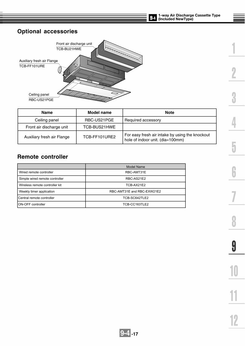
9-4 -17
Optional accessories
Remote controller
Name Model name Note
Required accessory
For easy fresh air intake by using the knockout hole of indoor unit. (dia=100mm)
RBC-US21PGE
TCB-BUS21HWE
TCB-FF101URE2
Ceiling panel
Front air discharge unit
Auxiliary fresh air Flange
Ceiling panel
RBC-US21PGE
Front air discharge unit
TCB-BU21HWE
Auxiliary fresh air Flange
TCB-FF101URE
Weekly timer application
Model Name
RBC-AMT31E
RBC-AS21E2
TCB-AX21E2
RBC-AMT31E and RBC-EXW21E2
Wired remote controller
Simple wired remote controller
Wireless remote controller kit
Central remote controller
ON-OFF controller
TCB-SC642TLE2
TCB-CC163TLE2

9-5 -1
9-5-1. Specifications 50Hz
Specifications (50Hz)
Note 1 : The cooling capacities and electrical characteristics are measured under the conditions specified by JIS B 8615 based on thereference piping. The reference piping consists of 5 m of main piping and 2.5 m of branch piping connected with 0 meter height.
Note 2 : The sound level are measured in an anechoic chamber in accordance with JIS B8616. Normally, the values measured in theactual operating environment become larger than the indicated values due to the effects of external sound.
Note : Rated conditions Cooling : Indoor air temperature 27oC DB/19oC WB, Outdoor air temperature 35oC DBHeating : Indoor air temperature 20oC DB, Outdoor air temperature 7oC DB/6oC WB
Model name MMD-
Cooling/Heating capacity (Note 1) (kW)
Electricalcharacteris-t ics
Power supply
Running current (A)
Power consumption (kW)
Starting current (A)
Appearance Main unit
Main unit
Height (mm)
Width (mm)
Depth (mm)
Height (mm)
Width (mm)
Depth (mm)
Suctionceilingpanel
Total weighMain unit (kg)
Ceiling panel (kg)
Heat exchanger
Soundproof/Heat-insulating material
Fan unit
Fan
Standard air flow(High/Mid/Low)
(m3/h)
Motor (W)
External static pressure(factory setting)
(Pa)
External static pressure (W)
Air filter
Controller
Connectingpipe
Gas side (mm)
Liquid side (mm)
Drain port (Nominal dia. mm)
Sound pressure level (Note 2)(High/Mid/Low) (dB(A))
AP0071BH
2.2/2.5
1 phase 50Hz 230V (220-240V) (Separate power supply for indoor units is required.)
0.29
0.033
0.5
Zinc hot dipping steel plate
320
AP0091BH
2.8/3.2
AP0121BH
3.6/4.0
AP0151BH
4.5/5.0
AP0181BH
5.6/6.3
AP0241BH
7.1/8.0
AP0271BH
8.0/9.0
AP0301BH
9.0/10.0
AP0361BH
11.2/12.5
AP0481BH
14.0/16.0
0.34
0.039
0.59
0.43
0.050
0.75
0.52
0.060
0.90
0.61
0.071
1.05
0.83
0.107
1.44
0.98
0.128
1.70
550 700 1,000 1,350
800
9
630 780 1,080 1,430
500
28
3.5
32
4
43
6
55
7
Finned tube
Non-flammable insulation
Centrifugal fan
480(420/340)
570(490/400)
650(540/480)
780(660/540)
1,140(990/870)
1,260(1,080/870)
1,620(1,410/1,200)
1,980(1,710/1,490)
120
40
100
Standard filter (Long life filter)
Remote controller
O/ 9.5 O/ 12.7 O/ 15.9
O/ 9.5O/ 6.4
25 (Polyvinyl chloride tube)
30/28/26 31/29/27 32/30/28 33/31/29 34/32/29 36/34/32 38/36/32
Outerdimension
PMV Kit Not available
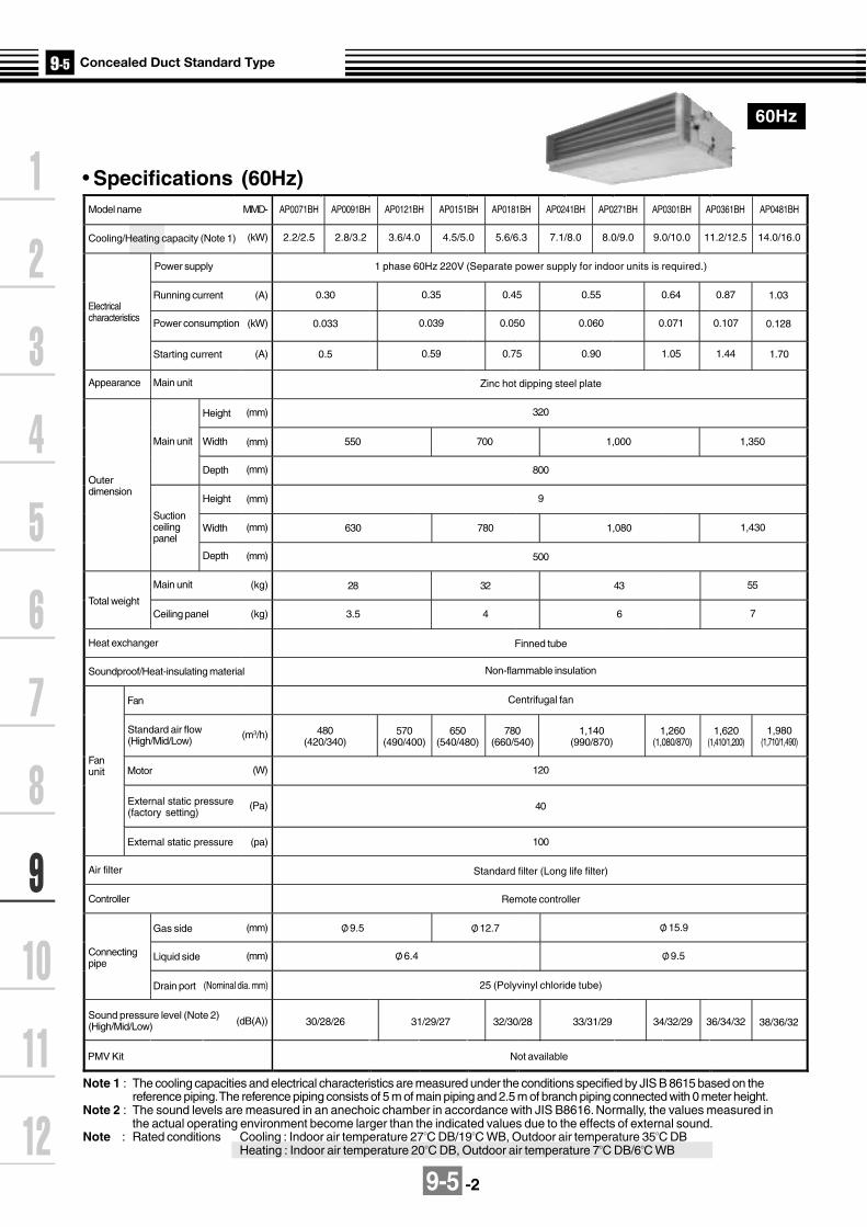
9-5 -2
60Hz
Model name MMD-
(kW)Cooling/Heating capacity (Note 1)
AP0071BH
2.2/2.5
Power supply
Electricalcharacteristics
Running current (A)
Power consumption
Starting current
Main unitAppearance
Outerdimension
Main unit
Height
Width
Depth
Height
Width
Depth
Suctionceilingpanel
Main unit
Total weightCeiling panel
Heat exchanger
Soundproof/Heat-insulating material
Fan
Motor
External static pressure
Fanunit
Standard air flow(High/Mid/Low)
External static pressure(factory setting)
Air filter
Controller
Connectingpipe
Gas side
Liquid side
Drain port
Sound pressure level (Note 2)(High/Mid/Low)
(kW)
(A)
(mm)
(mm)
(mm)
(mm)
(mm)
(mm)
(kg)
(kg)
(m3/h)
(W)
(Pa)
(pa)
(mm)
(mm)
(Nominal dia. mm)
(dB(A))
AP0091BH
2.8/3.2
AP0121BH
3.6/4.0
AP0151BH
4.5/5.0
AP0181BH
5.6/6.3
AP0241BH
7.1/8.0
AP0271BH
8.0/9.0
AP0301BH
9.0/10.0
AP0361BH
11.2/12.5
AP0481BH
14.0/16.0
1 phase 60Hz 220V (Separate power supply for indoor units is required.)
0.30 0.35 0.45 0.55 0.64 0.87 1.03
0.033 0.039 0.050 0.060 0.071 0.107 0.128
0.5 0.59 0.75 0.90 1.05 1.44 1.70
Zinc hot dipping steel plate
320
550 700 1,000 1,350
800
9
630 780 1,080 1,430
500
28 32 43 55
3.5 4 6 7
Finned tube
Non-flammable insulation
Centrifugal fan
480(420/340)
570(490/400)
650(540/480)
780(660/540)
1,140(990/870)
1,260(1,080/870)
1,620(1,410/1,200)
1,980(1,710/1,490)
120
40
100
Remote controller
Standard filter (Long life filter)
O/ 9.5 O/ 12.7 O/ 15.9
O/ 6.4 O/ 9.5
25 (Polyvinyl chloride tube)
30/28/26 31/29/27 32/30/28 33/31/29 34/32/29 36/34/32 38/36/32
Note 1 : The cooling capacities and electrical characteristics are measured under the conditions specified by JIS B 8615 based on thereference piping. The reference piping consists of 5 m of main piping and 2.5 m of branch piping connected with 0 meter height.
Note 2 : The sound levels are measured in an anechoic chamber in accordance with JIS B8616. Normally, the values measured inthe actual operating environment become larger than the indicated values due to the effects of external sound.
Note : Rated conditions Cooling : Indoor air temperature 27OC DB/19OC WB, Outdoor air temperature 35OC DBHeating : Indoor air temperature 20OC DB, Outdoor air temperature 7OC DB/6OC WB
PMV Kit Not available
Specifications (60Hz)

9-5 -3
ø125 knockout hole(For air intake)
10-ø4 tapping screw ø160
100mm or less
Panel C, L
150
91
Drain-up piping
550m
m o
r les
s
271m
m o
r les
s
450mm
Air outlet
Check port B
450mmCheck port A
Air filter700mm for maintenance of air filter 700mm for
maintenance of air filter
Ceiling opening part
(150mm)
300m
m
ø26 power supply, remote controller wires drawing-out port
Ceiling opendimension D
E
Air Suction
B
C 142
70 to
270
240
Drain pipe connecting port(Inner ø32 vinyl chloride pipe VP25 connection)
Hanging bolt 4-M10 (Procured locally)
Refrigerant pipe connecting port(Gas side øF)
Refrigerant pipe connecting port(Liquid side øG)
Unit external dimension 800
Hanging bolt pitch 700
Hanging bolt pitch A ± 7.5
44
50 638498
41 59
25 40
49(Whe
n at
tach
ing
dire
ctly
)
Ceiling opening470
393
196
50 50 24313
1
41
215 Air
DischargeAirSuction
Model MMD-
AP0071BH, AP0091BH, AP0121BH
AP0151BH, AP0181BH
AP0241BH, AP0271BH, AP0301BH
AP0361BH, AP0481BH
A616
766
1066
1416
B550
700
1000
1350
C350
500
800
1150
D600
750
1050
1400
E470
620
920
1270
F9.5
12.7
15.9
15.9
(Note)Be sure to create a check port at position A as indicatedin the following figure. This is for maintenance of theequipment.
Note: All dimensions are in mm.
Wired remote controller RBC-AMT31E
Simple wired remote controller RBC-AS21E2
Wireless remote controller kit TCB-AX21E2
Weekly timer application RBC-AMT31E and RBC-EXW21E2
G6.4
9.4
9.5
9.5(Note)Two of high efficiency filters availableDeodorant filter not available
MMD-AP0071BH, AP0091BH, AP0121BH, AP0151BH, AP0181BH, AP0241BH,
AP0271BH, AP0301BH, AP0361BH, AP0481BH
9-5-2. Dimension

9-5-4
Mo
del: M
MD
-AP
0071BH
, AP
0091BH
, AP
0121BH
, AP
0151BH
, AP
0181BH
, AP
0241BH
MM
D-A
P0271B
H, A
P0301B
H, A
P0361B
H, A
P0481B
H, A
P0561B
H
CN104(YEL)
CN102(RED)
CN101(BLK)
1 2 3 4 51 2 3 4 5 61 2 3 4 5 6
6 4 3 1 2 56 4 3 1 2 5
3 13 2 1
CN34(RED)
FS
CN33(WHI)
CN82(BLU)
DC20V
CN68(BLU)
CN304(GRY)
CN66(WHI)
CN44(BRW)
CN67(BLK)
Reactor
PMV
12
12
TA12
12
TCJ12
12
TC2
CN100(BRN)
12
12
33
CN80(GRN)
PNL
EXCT
12
CN73(RED)
12
(Signal output)(Fan drive)
CN70(WHI)
CN20(BLU)
12
3
TC1
1 2 3 4 5
CN81(BLK)
CN60(WHI)
CN32(WHI)
CN61(YEL)
CN50(WHI)
Adaputor for wiredremote controller
CN309(YEL)
CN41(BLU)
CN40(BLU)
T10 1 2 3 4 51 21 2 3 4 5 61 2 3 4 51 2 31 2 31 2 3
1 2 31 2
1 21 2 3
1 31 2 2
4 5 6
1 21 2
RY302123
123
123
123
12
12
12
3
~ +
~ Ð
FuseT6.3A
250V~
FuseT3.15A
250V~ DC15VDC12VDC7V
P301BLK
RED
WHI
WHIWHIRED
Wired remote controller
1 2
BA
S(N)R(L)
U2
1 2
CN1(WHI)
CN001(WHI)
Indoor unit power supplySingle phase
220-240V 50Hz 220V 60Hz
Indoor unit
Earth screw
WHI
Outdoor unit
BLK WHI BLK
BLK
BLU
BLU
BLK
BLK
TR
WHI
U1
U2U1
DM
Powersupplycircuit
Motor drive circuit
CN01(WHI)
CN02(BLU) CN03
(RED)
Network adaptor(Option)
1 21 2
1 21 2
X Y
3 32 21 1
Network adaptorP.C. board
Closed end connector
CN333(WHI)
CN334(WHI)
11
22
344
55
1 3 51 3
1 2 31 2 3
5
11
54
54
FM
Flow selector unit earth
screw
Indoor control P.C. board
Color identificationRED : REDWHI : WHITEYEL : YELLOWBLU : BLUEBRN : BROWN
BLK : BLACKGRY : GRAYPNK : PINKORN : ORANGEGRN : GREEN
Symbol
FM
TA
TC1,TC2,TCJ
D M
FS
RY302
PMV
Parts name
Fan motor
Indoor temp sensor
Indoor temp sensor
Drain pump motor
Float switch
Drain pump control relay
Pulse Motor Valve
1. indicates the terminal block, the letter inside indicates
the terminal number.
2. A dotted line and broken line indicate the wiring on site.
3. indicates the control P.C. board.
9-5-3. Wirin
g d
iagram

9-5 -5
TC : Total Capacity (kW) SHC : Sensible Heat Capacity (kW)Indoor air temp.
Unit Outdoor 16.0˚CWB 18.0˚CWB 19.0˚CWB 20.0˚CWB 22.0˚CWB 24.0˚CWBsize air temp. 23˚CDB 26˚CDB 27˚CDB 28˚CDB 30˚CDB 32˚CDB
˚CDB TC SHC TC SHC TC SHC TC SHC TC SHC TC SHC10.0 2.0 1.6 2.1 1.7 2.2 1.7 2.3 1.7 2.4 1.7 2.5 1.612.0 2.0 1.6 2.1 1.7 2.2 1.7 2.3 1.7 2.4 1.7 2.5 1.614.0 2.0 1.6 2.1 1.7 2.2 1.7 2.3 1.7 2.4 1.7 2.5 1.616.0 2.0 1.6 2.1 1.7 2.2 1.7 2.3 1.7 2.4 1.7 2.5 1.618.0 2.0 1.6 2.1 1.7 2.2 1.7 2.3 1.7 2.4 1.7 2.5 1.620.0 2.0 1.6 2.1 1.7 2.2 1.7 2.3 1.7 2.4 1.7 2.5 1.621.0 2.0 1.6 2.1 1.7 2.2 1.7 2.3 1.7 2.4 1.7 2.5 1.6
007 23.0 2.0 1.6 2.1 1.7 2.2 1.7 2.3 1.7 2.4 1.7 2.5 1.625.0 2.0 1.6 2.1 1.7 2.2 1.7 2.3 1.7 2.4 1.7 2.5 1.627.0 2.0 1.6 2.1 1.7 2.2 1.7 2.3 1.7 2.4 1.7 2.5 1.629.0 2.0 1.6 2.1 1.7 2.2 1.7 2.3 1.7 2.4 1.7 2.5 1.631.0 2.0 1.6 2.1 1.7 2.2 1.7 2.3 1.7 2.4 1.7 2.5 1.633.0 2.0 1.6 2.1 1.7 2.2 1.7 2.3 1.7 2.4 1.7 2.5 1.635.0 2.0 1.6 2.1 1.7 2.2 1.7 2.3 1.7 2.4 1.7 2.5 1.637.0 2.0 1.6 2.1 1.7 2.2 1.7 2.2 1.7 2.4 1.7 2.5 1.639.0 1.9 1.5 2.0 1.6 2.1 1.6 2.2 1.6 2.3 1.6 2.4 1.510.0 2.5 2.0 2.7 2.1 2.8 2.1 2.9 2.1 3.1 2.1 3.2 2.012.0 2.5 2.0 2.7 2.1 2.8 2.1 2.9 2.1 3.1 2.1 3.2 2.014.0 2.5 2.0 2.7 2.1 2.8 2.1 2.9 2.1 3.1 2.1 3.2 2.016.0 2.5 2.0 2.7 2.1 2.8 2.1 2.9 2.1 3.1 2.1 3.2 2.018.0 2.5 2.0 2.7 2.1 2.8 2.1 2.9 2.1 3.1 2.1 3.2 2.020.0 2.5 2.0 2.7 2.1 2.8 2.1 2.9 2.1 3.1 2.1 3.2 2.021.0 2.5 2.0 2.7 2.1 2.8 2.1 2.9 2.1 3.1 2.1 3.2 2.0
009 23.0 2.5 2.0 2.7 2.1 2.8 2.1 2.9 2.1 3.1 2.1 3.2 2.025.0 2.5 2.0 2.7 2.1 2.8 2.1 2.9 2.1 3.1 2.1 3.2 2.027.0 2.5 2.0 2.7 2.1 2.8 2.1 2.9 2.1 3.1 2.1 3.2 2.029.0 2.5 2.0 2.7 2.1 2.8 2.1 2.9 2.1 3.1 2.1 3.2 2.031.0 2.5 2.0 2.7 2.1 2.8 2.1 2.9 2.1 3.1 2.1 3.2 2.033.0 2.5 2.0 2.7 2.1 2.8 2.1 2.9 2.1 3.1 2.1 3.2 2.035.0 2.5 2.0 2.7 2.1 2.8 2.1 2.9 2.1 3.1 2.1 3.2 2.037.0 2.5 1.9 2.7 2.1 2.7 2.1 2.8 2.1 3.0 2.0 3.1 2.039.0 2.4 1.9 2.6 2.0 2.7 2.0 2.8 2.0 2.9 2.0 3.1 1.910.0 3.3 2.4 3.5 2.5 3.6 2.5 3.7 2.5 3.9 2.5 4.1 2.412.0 3.3 2.4 3.5 2.5 3.6 2.5 3.7 2.5 3.9 2.5 4.1 2.414.0 3.3 2.4 3.5 2.5 3.6 2.5 3.7 2.5 3.9 2.5 4.1 2.416.0 3.3 2.4 3.5 2.5 3.6 2.5 3.7 2.5 3.9 2.5 4.1 2.418.0 3.3 2.4 3.5 2.5 3.6 2.5 3.7 2.5 3.9 2.5 4.1 2.420.0 3.3 2.4 3.5 2.5 3.6 2.5 3.7 2.5 3.9 2.5 4.1 2.421.0 3.3 2.4 3.5 2.5 3.6 2.5 3.7 2.5 3.9 2.5 4.1 2.4
012 23.0 3.3 2.4 3.5 2.5 3.6 2.5 3.7 2.5 3.9 2.5 4.1 2.425.0 3.3 2.4 3.5 2.5 3.6 2.5 3.7 2.5 3.9 2.5 4.1 2.427.0 3.3 2.4 3.5 2.5 3.6 2.5 3.7 2.5 3.9 2.5 4.1 2.429.0 3.3 2.4 3.5 2.5 3.6 2.5 3.7 2.5 3.9 2.5 4.1 2.431.0 3.3 2.4 3.5 2.5 3.6 2.5 3.7 2.5 3.9 2.5 4.1 2.433.0 3.3 2.4 3.5 2.5 3.6 2.5 3.7 2.5 3.9 2.5 4.1 2.435.0 3.3 2.4 3.5 2.5 3.6 2.5 3.7 2.5 3.9 2.5 4.1 2.437.0 3.2 2.3 3.4 2.5 3.5 2.5 3.6 2.4 3.8 2.4 4.0 2.439.0 3.1 2.2 3.4 2.4 3.5 2.4 3.6 2.4 3.8 2.3 3.9 2.310.0 4.1 2.8 4.4 3.0 4.5 3.0 4.6 3.0 4.9 3.0 5.1 2.912.0 4.1 2.8 4.4 3.0 4.5 3.0 4.6 3.0 4.9 3.0 5.1 2.914.0 4.1 2.8 4.4 3.0 4.5 3.0 4.6 3.0 4.9 3.0 5.1 2.916.0 4.1 2.8 4.4 3.0 4.5 3.0 4.6 3.0 4.9 3.0 5.1 2.918.0 4.1 2.8 4.4 3.0 4.5 3.0 4.6 3.0 4.9 3.0 5.1 2.920.0 4.1 2.8 4.4 3.0 4.5 3.0 4.6 3.0 4.9 3.0 5.1 2.921.0 4.1 2.8 4.4 3.0 4.5 3.0 4.6 3.0 4.9 3.0 5.1 2.9
015 23.0 4.1 2.8 4.4 3.0 4.5 3.0 4.6 3.0 4.9 3.0 5.1 2.925.0 4.1 2.8 4.4 3.0 4.5 3.0 4.6 3.0 4.9 3.0 5.1 2.927.0 4.1 2.8 4.4 3.0 4.5 3.0 4.6 3.0 4.9 3.0 5.1 2.929.0 4.1 2.8 4.4 3.0 4.5 3.0 4.6 3.0 4.9 3.0 5.1 2.931.0 4.1 2.8 4.4 3.0 4.5 3.0 4.6 3.0 4.9 3.0 5.1 2.933.0 4.1 2.8 4.4 3.0 4.5 3.0 4.6 3.0 4.9 3.0 5.1 2.935.0 4.1 2.8 4.4 3.0 4.5 3.0 4.6 3.0 4.9 3.0 5.1 2.937.0 4.0 2.8 4.3 2.9 4.4 2.9 4.5 2.9 4.8 2.9 5.0 2.839.0 3.9 2.7 4.2 2.8 4.3 2.8 4.4 2.8 4.7 2.8 4.9 2.7
9-5-4. Sensible capacity table(MMD-AP***BH)
Cooling capacity
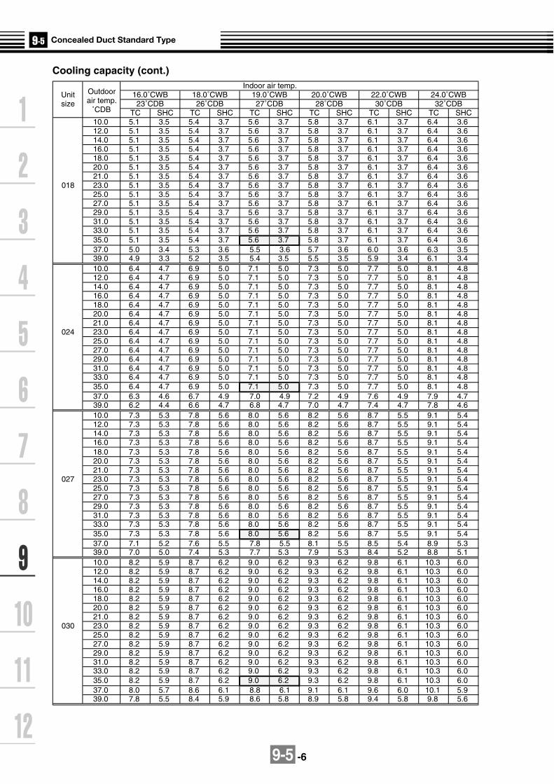
9-5 -6
Cooling capacity (cont.)Indoor air temp.
Unit Outdoor 16.0˚CWB 18.0˚CWB 19.0˚CWB 20.0˚CWB 22.0˚CWB 24.0˚CWBsize air temp. 23˚CDB 26˚CDB 27˚CDB 28˚CDB 30˚CDB 32˚CDB
˚CDB TC SHC TC SHC TC SHC TC SHC TC SHC TC SHC10.0 5.1 3.5 5.4 3.7 5.6 3.7 5.8 3.7 6.1 3.7 6.4 3.612.0 5.1 3.5 5.4 3.7 5.6 3.7 5.8 3.7 6.1 3.7 6.4 3.614.0 5.1 3.5 5.4 3.7 5.6 3.7 5.8 3.7 6.1 3.7 6.4 3.616.0 5.1 3.5 5.4 3.7 5.6 3.7 5.8 3.7 6.1 3.7 6.4 3.618.0 5.1 3.5 5.4 3.7 5.6 3.7 5.8 3.7 6.1 3.7 6.4 3.620.0 5.1 3.5 5.4 3.7 5.6 3.7 5.8 3.7 6.1 3.7 6.4 3.621.0 5.1 3.5 5.4 3.7 5.6 3.7 5.8 3.7 6.1 3.7 6.4 3.6
018 23.0 5.1 3.5 5.4 3.7 5.6 3.7 5.8 3.7 6.1 3.7 6.4 3.625.0 5.1 3.5 5.4 3.7 5.6 3.7 5.8 3.7 6.1 3.7 6.4 3.627.0 5.1 3.5 5.4 3.7 5.6 3.7 5.8 3.7 6.1 3.7 6.4 3.629.0 5.1 3.5 5.4 3.7 5.6 3.7 5.8 3.7 6.1 3.7 6.4 3.631.0 5.1 3.5 5.4 3.7 5.6 3.7 5.8 3.7 6.1 3.7 6.4 3.633.0 5.1 3.5 5.4 3.7 5.6 3.7 5.8 3.7 6.1 3.7 6.4 3.635.0 5.1 3.5 5.4 3.7 5.6 3.7 5.8 3.7 6.1 3.7 6.4 3.637.0 5.0 3.4 5.3 3.6 5.5 3.6 5.7 3.6 6.0 3.6 6.3 3.539.0 4.9 3.3 5.2 3.5 5.4 3.5 5.5 3.5 5.9 3.4 6.1 3.410.0 6.4 4.7 6.9 5.0 7.1 5.0 7.3 5.0 7.7 5.0 8.1 4.812.0 6.4 4.7 6.9 5.0 7.1 5.0 7.3 5.0 7.7 5.0 8.1 4.814.0 6.4 4.7 6.9 5.0 7.1 5.0 7.3 5.0 7.7 5.0 8.1 4.816.0 6.4 4.7 6.9 5.0 7.1 5.0 7.3 5.0 7.7 5.0 8.1 4.818.0 6.4 4.7 6.9 5.0 7.1 5.0 7.3 5.0 7.7 5.0 8.1 4.820.0 6.4 4.7 6.9 5.0 7.1 5.0 7.3 5.0 7.7 5.0 8.1 4.821.0 6.4 4.7 6.9 5.0 7.1 5.0 7.3 5.0 7.7 5.0 8.1 4.8
024 23.0 6.4 4.7 6.9 5.0 7.1 5.0 7.3 5.0 7.7 5.0 8.1 4.825.0 6.4 4.7 6.9 5.0 7.1 5.0 7.3 5.0 7.7 5.0 8.1 4.827.0 6.4 4.7 6.9 5.0 7.1 5.0 7.3 5.0 7.7 5.0 8.1 4.829.0 6.4 4.7 6.9 5.0 7.1 5.0 7.3 5.0 7.7 5.0 8.1 4.831.0 6.4 4.7 6.9 5.0 7.1 5.0 7.3 5.0 7.7 5.0 8.1 4.833.0 6.4 4.7 6.9 5.0 7.1 5.0 7.3 5.0 7.7 5.0 8.1 4.835.0 6.4 4.7 6.9 5.0 7.1 5.0 7.3 5.0 7.7 5.0 8.1 4.837.0 6.3 4.6 6.7 4.9 7.0 4.9 7.2 4.9 7.6 4.9 7.9 4.739.0 6.2 4.4 6.6 4.7 6.8 4.7 7.0 4.7 7.4 4.7 7.8 4.610.0 7.3 5.3 7.8 5.6 8.0 5.6 8.2 5.6 8.7 5.5 9.1 5.412.0 7.3 5.3 7.8 5.6 8.0 5.6 8.2 5.6 8.7 5.5 9.1 5.414.0 7.3 5.3 7.8 5.6 8.0 5.6 8.2 5.6 8.7 5.5 9.1 5.416.0 7.3 5.3 7.8 5.6 8.0 5.6 8.2 5.6 8.7 5.5 9.1 5.418.0 7.3 5.3 7.8 5.6 8.0 5.6 8.2 5.6 8.7 5.5 9.1 5.420.0 7.3 5.3 7.8 5.6 8.0 5.6 8.2 5.6 8.7 5.5 9.1 5.421.0 7.3 5.3 7.8 5.6 8.0 5.6 8.2 5.6 8.7 5.5 9.1 5.4
027 23.0 7.3 5.3 7.8 5.6 8.0 5.6 8.2 5.6 8.7 5.5 9.1 5.425.0 7.3 5.3 7.8 5.6 8.0 5.6 8.2 5.6 8.7 5.5 9.1 5.427.0 7.3 5.3 7.8 5.6 8.0 5.6 8.2 5.6 8.7 5.5 9.1 5.429.0 7.3 5.3 7.8 5.6 8.0 5.6 8.2 5.6 8.7 5.5 9.1 5.431.0 7.3 5.3 7.8 5.6 8.0 5.6 8.2 5.6 8.7 5.5 9.1 5.433.0 7.3 5.3 7.8 5.6 8.0 5.6 8.2 5.6 8.7 5.5 9.1 5.435.0 7.3 5.3 7.8 5.6 8.0 5.6 8.2 5.6 8.7 5.5 9.1 5.437.0 7.1 5.2 7.6 5.5 7.8 5.5 8.1 5.5 8.5 5.4 8.9 5.339.0 7.0 5.0 7.4 5.3 7.7 5.3 7.9 5.3 8.4 5.2 8.8 5.110.0 8.2 5.9 8.7 6.2 9.0 6.2 9.3 6.2 9.8 6.1 10.3 6.012.0 8.2 5.9 8.7 6.2 9.0 6.2 9.3 6.2 9.8 6.1 10.3 6.014.0 8.2 5.9 8.7 6.2 9.0 6.2 9.3 6.2 9.8 6.1 10.3 6.016.0 8.2 5.9 8.7 6.2 9.0 6.2 9.3 6.2 9.8 6.1 10.3 6.018.0 8.2 5.9 8.7 6.2 9.0 6.2 9.3 6.2 9.8 6.1 10.3 6.020.0 8.2 5.9 8.7 6.2 9.0 6.2 9.3 6.2 9.8 6.1 10.3 6.021.0 8.2 5.9 8.7 6.2 9.0 6.2 9.3 6.2 9.8 6.1 10.3 6.0
030 23.0 8.2 5.9 8.7 6.2 9.0 6.2 9.3 6.2 9.8 6.1 10.3 6.025.0 8.2 5.9 8.7 6.2 9.0 6.2 9.3 6.2 9.8 6.1 10.3 6.027.0 8.2 5.9 8.7 6.2 9.0 6.2 9.3 6.2 9.8 6.1 10.3 6.029.0 8.2 5.9 8.7 6.2 9.0 6.2 9.3 6.2 9.8 6.1 10.3 6.031.0 8.2 5.9 8.7 6.2 9.0 6.2 9.3 6.2 9.8 6.1 10.3 6.033.0 8.2 5.9 8.7 6.2 9.0 6.2 9.3 6.2 9.8 6.1 10.3 6.035.0 8.2 5.9 8.7 6.2 9.0 6.2 9.3 6.2 9.8 6.1 10.3 6.037.0 8.0 5.7 8.6 6.1 8.8 6.1 9.1 6.1 9.6 6.0 10.1 5.939.0 7.8 5.5 8.4 5.9 8.6 5.8 8.9 5.8 9.4 5.8 9.8 5.6

9-5 -7
Cooling capacity (cont.)Indoor air temp.
Unit Outdoor 16.0˚CWB 18.0˚CWB 19.0˚CWB 20.0˚CWB 22.0˚CWB 24.0˚CWBsize air temp. 23˚CDB 26˚CDB 27˚CDB 28˚CDB 30˚CDB 32˚CDB
˚CDB TC SHC TC SHC TC SHC TC SHC TC SHC TC SHC10.0 10.2 6.9 10.9 7.3 11.2 7.3 11.5 7.3 12.2 7.2 12.8 7.112.0 10.2 6.9 10.9 7.3 11.2 7.3 11.5 7.3 12.2 7.2 12.8 7.114.0 10.2 6.9 10.9 7.3 11.2 7.3 11.5 7.3 12.2 7.2 12.8 7.116.0 10.2 6.9 10.9 7.3 11.2 7.3 11.5 7.3 12.2 7.2 12.8 7.118.0 10.2 6.9 10.9 7.3 11.2 7.3 11.5 7.3 12.2 7.2 12.8 7.120.0 10.2 6.9 10.9 7.3 11.2 7.3 11.5 7.3 12.2 7.2 12.8 7.121.0 10.2 6.9 10.9 7.3 11.2 7.3 11.5 7.3 12.2 7.2 12.8 7.1
036 23.0 10.2 6.9 10.9 7.3 11.2 7.3 11.5 7.3 12.2 7.2 12.8 7.125.0 10.2 6.9 10.9 7.3 11.2 7.3 11.5 7.3 12.2 7.2 12.8 7.127.0 10.2 6.9 10.9 7.3 11.2 7.3 11.5 7.3 12.2 7.2 12.8 7.129.0 10.2 6.9 10.9 7.3 11.2 7.3 11.5 7.3 12.2 7.2 12.8 7.131.0 10.2 6.9 10.9 7.3 11.2 7.3 11.5 7.3 12.2 7.2 12.8 7.133.0 10.2 6.9 10.9 7.3 11.2 7.3 11.5 7.3 12.2 7.2 12.8 7.135.0 10.2 6.9 10.9 7.3 11.2 7.3 11.5 7.3 12.2 7.2 12.8 7.137.0 10.0 6.8 10.6 7.2 11.0 7.2 11.3 7.2 12.0 7.1 12.5 6.939.0 9.8 6.5 10.4 6.9 10.8 6.9 11.1 6.9 11.7 6.8 12.3 6.610.0 12.7 8.7 13.6 9.2 14.0 9.2 14.4 9.2 15.3 9.1 16.0 8.912.0 12.7 8.7 13.6 9.2 14.0 9.2 14.4 9.2 15.3 9.1 16.0 8.914.0 12.7 8.7 13.6 9.2 14.0 9.2 14.4 9.2 15.3 9.1 16.0 8.916.0 12.7 8.7 13.6 9.2 14.0 9.2 14.4 9.2 15.3 9.1 16.0 8.918.0 12.7 8.7 13.6 9.2 14.0 9.2 14.4 9.2 15.3 9.1 16.0 8.920.0 12.7 8.7 13.6 9.2 14.0 9.2 14.4 9.2 15.3 9.1 16.0 8.921.0 12.7 8.7 13.6 9.2 14.0 9.2 14.4 9.2 15.3 9.1 16.0 8.9
048 23.0 12.7 8.7 13.6 9.2 14.0 9.2 14.4 9.2 15.3 9.1 16.0 8.925.0 12.7 8.7 13.6 9.2 14.0 9.2 14.4 9.2 15.3 9.1 16.0 8.927.0 12.7 8.7 13.6 9.2 14.0 9.2 14.4 9.2 15.3 9.1 16.0 8.929.0 12.7 8.7 13.6 9.2 14.0 9.2 14.4 9.2 15.3 9.1 16.0 8.931.0 12.7 8.7 13.6 9.2 14.0 9.2 14.4 9.2 15.3 9.1 16.0 8.933.0 12.7 8.7 13.6 9.2 14.0 9.2 14.4 9.2 15.3 9.1 16.0 8.935.0 12.7 8.7 13.6 9.2 14.0 9.2 14.4 9.2 15.3 9.1 16.0 8.937.0 12.5 8.5 13.3 9.0 13.7 9.0 14.1 9.0 15.0 8.9 15.6 8.739.0 12.2 8.2 13.0 8.7 13.4 8.7 13.8 8.7 14.6 8.6 15.3 8.4
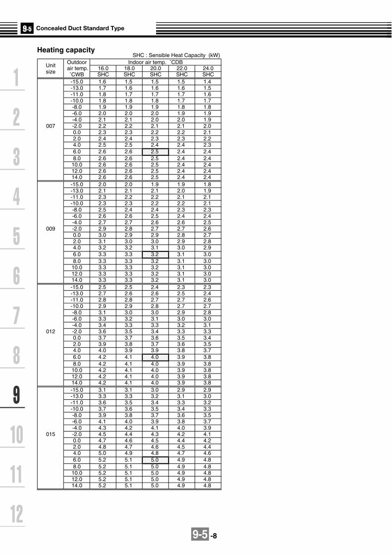
9-5 -8
SHC : Sensible Heat Capacity (kW)
UnitOutdoor Indoor air temp. ˚CDB
size air temp. 16.0 18.0 20.0 22.0 24.0
˚CWB SHC SHC SHC SHC SHC-15.0 1.6 1.5 1.5 1.5 1.4-13.0 1.7 1.6 1.6 1.6 1.5-11.0 1.8 1.7 1.7 1.7 1.6-10.0 1.8 1.8 1.8 1.7 1.7-8.0 1.9 1.9 1.9 1.8 1.8-6.0 2.0 2.0 2.0 1.9 1.9-4.0 2.1 2.1 2.0 2.0 1.9
007 -2.0 2.2 2.2 2.1 2.1 2.00.0 2.3 2.3 2.2 2.2 2.12.0 2.4 2.4 2.3 2.3 2.24.0 2.5 2.5 2.4 2.4 2.36.0 2.6 2.6 2.5 2.4 2.48.0 2.6 2.6 2.5 2.4 2.4
10.0 2.6 2.6 2.5 2.4 2.412.0 2.6 2.6 2.5 2.4 2.414.0 2.6 2.6 2.5 2.4 2.4-15.0 2.0 2.0 1.9 1.9 1.8-13.0 2.1 2.1 2.1 2.0 1.9-11.0 2.3 2.2 2.2 2.1 2.1-10.0 2.3 2.3 2.2 2.2 2.1-8.0 2.5 2.4 2.4 2.3 2.3-6.0 2.6 2.6 2.5 2.4 2.4-4.0 2.7 2.7 2.6 2.6 2.5
009 -2.0 2.9 2.8 2.7 2.7 2.60.0 3.0 2.9 2.9 2.8 2.72.0 3.1 3.0 3.0 2.9 2.84.0 3.2 3.2 3.1 3.0 2.96.0 3.3 3.3 3.2 3.1 3.08.0 3.3 3.3 3.2 3.1 3.0
10.0 3.3 3.3 3.2 3.1 3.012.0 3.3 3.3 3.2 3.1 3.014.0 3.3 3.3 3.2 3.1 3.0-15.0 2.5 2.5 2.4 2.3 2.3-13.0 2.7 2.6 2.6 2.5 2.4-11.0 2.8 2.8 2.7 2.7 2.6-10.0 2.9 2.9 2.8 2.7 2.7-8.0 3.1 3.0 3.0 2.9 2.8-6.0 3.3 3.2 3.1 3.0 3.0-4.0 3.4 3.3 3.3 3.2 3.1
012 -2.0 3.6 3.5 3.4 3.3 3.30.0 3.7 3.7 3.6 3.5 3.42.0 3.9 3.8 3.7 3.6 3.54.0 4.0 3.9 3.9 3.8 3.76.0 4.2 4.1 4.0 3.9 3.88.0 4.2 4.1 4.0 3.9 3.8
10.0 4.2 4.1 4.0 3.9 3.812.0 4.2 4.1 4.0 3.9 3.814.0 4.2 4.1 4.0 3.9 3.8-15.0 3.1 3.1 3.0 2.9 2.9-13.0 3.3 3.3 3.2 3.1 3.0-11.0 3.6 3.5 3.4 3.3 3.2-10.0 3.7 3.6 3.5 3.4 3.3-8.0 3.9 3.8 3.7 3.6 3.5-6.0 4.1 4.0 3.9 3.8 3.7-4.0 4.3 4.2 4.1 4.0 3.9
015 -2.0 4.5 4.4 4.3 4.2 4.10.0 4.7 4.6 4.5 4.4 4.22.0 4.8 4.7 4.6 4.5 4.44.0 5.0 4.9 4.8 4.7 4.66.0 5.2 5.1 5.0 4.9 4.88.0 5.2 5.1 5.0 4.9 4.8
10.0 5.2 5.1 5.0 4.9 4.812.0 5.2 5.1 5.0 4.9 4.814.0 5.2 5.1 5.0 4.9 4.8
Heating capacity

9-5 -9
Unit Outdoor Indoor air temp. ˚CDB
size air temp. 16.0 18.0 20.0 22.0 24.0
˚CWB SHC SHC SHC SHC SHC-15.0 3.9 3.9 3.8 3.7 3.6-13.0 4.2 4.1 4.0 3.9 3.8-11.0 4.5 4.4 4.3 4.2 4.1-10.0 4.6 4.5 4.4 4.3 4.2-8.0 4.9 4.8 4.7 4.6 4.4-6.0 5.1 5.0 4.9 4.8 4.7-4.0 5.4 5.3 5.2 5.0 4.9
018 -2.0 5.6 5.5 5.4 5.3 5.10.0 5.9 5.8 5.6 5.5 5.32.0 6.1 6.0 5.9 5.7 5.64.0 6.3 6.2 6.1 5.9 5.86.0 6.6 6.4 6.3 6.1 6.08.0 6.6 6.4 6.3 6.1 6.0
10.0 6.6 6.4 6.3 6.1 6.012.0 6.6 6.4 6.3 6.1 6.014.0 6.6 6.4 6.3 6.1 6.0-15.0 5.0 4.9 4.8 4.7 4.6-13.0 5.3 5.2 5.1 5.0 4.9-11.0 5.7 5.6 5.5 5.3 5.2-10.0 5.8 5.7 5.6 5.5 5.3-8.0 6.2 6.1 5.9 5.8 5.6-6.0 6.5 6.4 6.2 6.1 5.9-4.0 6.8 6.7 6.6 6.4 6.2
024 -2.0 7.1 7.0 6.9 6.7 6.50.0 7.4 7.3 7.1 7.0 6.82.0 7.7 7.6 7.4 7.3 7.14.0 8.0 7.9 7.7 7.5 7.36.0 8.3 8.2 8.0 7.8 7.68.0 8.3 8.2 8.0 7.8 7.6
10.0 8.3 8.2 8.0 7.8 7.612.0 8.3 8.2 8.0 7.8 7.614.0 8.3 8.2 8.0 7.8 7.6-15.0 5.6 5.5 5.4 5.3 5.1-13.0 6.0 5.9 5.8 5.6 5.5-11.0 6.4 6.3 6.1 6.0 5.8-10.0 6.6 6.5 6.3 6.2 6.0-8.0 7.0 6.8 6.7 6.5 6.3-6.0 7.3 7.2 7.0 6.9 6.7-4.0 7.7 7.5 7.4 7.2 7.0
027 -2.0 8.0 7.9 7.7 7.5 7.30.0 8.4 8.2 8.0 7.8 7.62.0 8.7 8.5 8.4 8.2 7.94.0 9.0 8.9 8.7 8.5 8.36.0 9.4 9.2 9.0 8.8 8.68.0 9.4 9.2 9.0 8.8 8.6
10.0 9.4 9.2 9.0 8.8 8.612.0 9.4 9.2 9.0 8.8 8.614.0 9.4 9.2 9.0 8.8 8.6-15.0 6.3 6.1 6.0 5.9 5.7-13.0 6.7 6.6 6.4 6.3 6.1-11.0 7.1 7.0 6.8 6.7 6.5-10.0 7.3 7.2 7.0 6.9 6.7-8.0 7.7 7.6 7.4 7.2 7.0-6.0 8.1 8.0 7.8 7.6 7.4-4.0 8.5 8.4 8.2 8.0 7.8
030 -2.0 8.9 8.8 8.6 8.4 8.10.0 9.3 9.1 8.9 8.7 8.52.0 9.7 9.5 9.3 9.1 8.84.0 10.0 9.9 9.7 9.4 9.26.0 10.4 10.2 10.0 9.8 9.58.0 10.4 10.2 10.0 9.8 9.5
10.0 10.4 10.2 10.0 9.8 9.512.0 10.4 10.2 10.0 9.8 9.514.0 10.4 10.2 10.0 9.8 9.5
Heating capacity (cont.)

9-5 -10
Unit Outdoor Indoor air temp. ˚CDB
size air temp. 16.0 18.0 20.0 22.0 24.0˚CWB SHC SHC SHC SHC SHC-15.0 7.8 7.7 7.5 7.3 7.2-13.0 8.3 8.2 8.0 7.8 7.6-11.0 8.9 8.7 8.5 8.3 8.1-10.0 9.1 9.0 8.8 8.6 8.3-8.0 9.7 9.5 9.3 9.1 8.8-6.0 10.2 10.0 9.8 9.5 9.3-4.0 10.7 10.5 10.2 10.0 9.7
036 -2.0 11.1 10.9 10.7 10.5 10.20.0 11.6 11.4 11.2 10.9 10.62.0 12.1 11.9 11.6 11.3 11.04.0 12.6 12.3 12.1 11.8 11.56.0 13.0 12.8 12.5 12.2 11.98.0 13.0 12.8 12.5 12.2 11.9
10.0 13.0 12.8 12.5 12.2 11.912.0 13.0 12.8 12.5 12.2 11.914.0 13.0 12.8 12.5 12.2 11.9-15.0 10.0 9.8 9.6 9.4 9.1-13.0 10.7 10.5 10.3 10.0 9.7-11.0 11.4 11.1 10.9 10.7 10.4-10.0 11.7 11.5 11.2 11.0 10.7-8.0 12.4 12.1 11.9 11.6 11.3-6.0 13.0 12.8 12.5 12.2 11.9-4.0 13.6 13.4 13.1 12.8 12.4
048 -2.0 14.3 14.0 13.7 13.4 13.00.0 14.9 14.6 14.3 14.0 13.62.0 15.5 15.2 14.9 14.5 14.14.0 16.1 15.8 15.4 15.1 14.76.0 16.7 16.3 16.0 15.6 15.28.0 16.7 16.3 16.0 15.6 15.2
10.0 16.7 16.3 16.0 15.6 15.212.0 16.7 16.3 16.0 15.6 15.214.0 16.7 16.3 16.0 15.6 15.2
Heating capacity (cont.)

9-5 -11
9-5-5. Fan characteristics
140
120
100
80
60
40
20
0200 400 600480
Ext
erna
l sta
tic p
ress
ure
(Pa)
Air volume (m³/h)
Standard air volume: 480m³/h
Air
volu
me
limit
(Max
)
Air
volu
me
limit
(Min
)
140
120
100
80
60
40
20
0300 500 570 700
Ext
erna
l sta
tic p
ress
ure
(Pa)
Air volume (m³/h)
Standard air volume: 570m³/h
High static pressure 1 (70 Pa)
Low static pressure (High)Standard pressure (20 Pa) (Low)
Standard static pressure (40 Pa) (High)
Air
volu
me
limit
(Min
)
140
120
100
80
60
40
20
0400 650600 800
Ext
erna
l sta
tic p
ress
ure
(Pa)
Air volume (m³/h)
Standard air volume: 650m³/h
High static pressure 1 (70 Pa)
Low static pressure (High)Standard pressure (20 Pa) (Low)
Standard static pressure (40 Pa) (High)
Air
volu
me
limit
(Max
)
Air
volu
me
limit
(Min
)
140
120
100
80
60
40
20
0500 700 780 900
Ext
erna
l sta
tic p
ress
ure
(Pa)
Air volume (m³/h)
Standard air volume: 780m³/h
High static pressure 2 (100 Pa)
High static pressure 1 (70 Pa)
Low static pressure (High)Standard pressure (20 Pa) (Low)
Standard static pressure (40 Pa) (High)
Air
volu
me
limit
(Max
)
Air
volu
me
limit
(Min
)
Air
volu
me
limit
(Max
)
Long life filter
Long life filter
Long life filter
Long life filter
High static pressure 2 (100 Pa)High static pressure 1 (70 Pa)
Low static pressure (High)Standard pressure (20 Pa) (Low)
Applic
atio
n lim
it
Application limit
Standard static pressure (40 Pa) (High)
High static pressure 2 (100 Pa)Applic
ation lim
it
High static pressure 2 (100 Pa)
Applicatio
n limit
MMD-AP0071BH, AP0091BH
MMD-AP0151BH
MMD-AP0121BH
MMD-AP0181BH
In case of square duct flange of discharge section
*Note: “High” and “Low” refers to air flow.

9-5 -12
140
120
100
80
60
40
20
0800 1000 1140 13001200
Ext
erna
l sta
tic p
ress
ure
(Pa)
Air volume (m³/h)
Standard air volume: 1140m³/h
High static pressure 2 (100 Pa)
High static pressure 1 (70 Pa)
Low static pressure (High)
Standard pressure (20 Pa) (Low)
Standard static pressure (40 Pa) (High)A
ir vo
lum
e lim
it (M
ax)
Air
volu
me
limit
(Min
)140
120
100
80
60
40
20
0900 1100 1260 1300
Ext
erna
l sta
tic p
ress
ure
(Pa)
Air volume (m³/h)
Standard air volume: 1260m³/h
High static pressure 2 (100 Pa)
High static pressure 1 (70 Pa)
Low static pressure (High)
Standard pressure (20 Pa) (Low)
Standard static pressure (40 Pa) (High) Air
volu
me
limit
(Max
)
Air
volu
me
limit
(Min
)
140
120
100
80
60
40
20
01200 1620 2000
Ext
erna
l sta
tic p
ress
ure
(Pa)
Air volume (m³/h)
Standard air volume: 1620m³/h
High static pressure 1 (70 Pa)
Low static pressure (High)
Standard pressure (20 Pa) (Low)
Standard static pressure (40 Pa) (High)
Air
volu
me
limit
(Max
)
Air
volu
me
lim
it (M
in)
140
120
100
80
60
40
20
01400 22001800 1980
Ext
erna
l sta
tic p
ress
ure
(Pa)
Air volume (m³/h)
Standard air volume: 1980m³/h
High static pressure 2 (100 Pa)
High static pressure 1 (70 Pa)
Low static pressure (High)
Standard pressure (20 Pa) (Low)
Standard static pressure (40 Pa) (High)
Air
volu
me
limit
(Max
)
Air
volu
me
limit
(Min
)
Long life filter Long life filter
Long life filterLong life filter
Application limit
Application limit
Application limit
Application limit
High static pressure 2 (100 Pa)
MMD-AP0241BH, AP0271BH
MMD-AP0361BH
MMD-AP0301BH
MMD-AP0481BH
*Note: “High” and “Low” refers to air flow.

9-5 -13
9-5-6. Sound characteristics (NC-Curve)
HM
L
10
20
30
40
50
60
70
80
90
63 125 250 500 1000 2000 4000 8000
NC-70
NC-60
NC-50
NC-40
NC-30
NC-20
H
ML
10
20
30
40
50
60
70
80
90
63 125 250 500 1000 2000 4000 8000
NC-70
NC-60
NC-50
NC-40
NC-30
NC-20
H
ML
10
20
30
40
50
60
70
80
90
63 125 250 500 1000 2000 4000 8000
NC-70
NC-60
NC-50
NC-40
NC-30
NC-20
HM
L
10
20
30
40
50
60
70
80
90
63 125 250 500 1000 2000 4000 8000
NC-70
NC-60
NC-50
NC-40
NC-30
NC-20
Microphone
MMD-AP0071BH, AP0091BH
MMD-AP0151BHMMD-AP0121BH
MMD-AP0181BH
Oct
ave
ba
nd
so
un
d p
ress
ure
le
vel
(dB
)
Octave band center frequency (Hz)
Audibility limits ofcontinuous white level
Oct
ave
ba
nd
so
un
d p
ress
ure
le
vel
(dB
)
Octave band center frequency (Hz)
Audibility limits ofcontinuous white level
Oct
ave
ba
nd
so
un
d p
ress
ure
le
vel
(dB
)
Audibility limits ofcontinuous white level
Octave band center frequency (Hz)
Audibility limits ofcontinuous white level
Octave band center frequency (Hz)
Oct
ave
ba
nd
so
un
d p
ress
ure
le
vel
(dB
)
Fan TapSound pressure level
(dB (A))
H
30
M
28
L
26
Fan TapSound pressure level
(dB (A))
H
31
M
29
L
27
Fan TapSound pressure level
(dB (A))
H
31
M
29
L
27
Fan TapOverall level
dB(A)
H
32
M
30
L
28

9-5 -14
10
20
30
40
50
60
70
80
90
63 125 250 500 1000 2000 4000 8000
NC-70
NC-60
NC-50
NC-40
NC-30
NC-20
10
20
30
40
50
60
70
80
90
63 125 250 500 1000 2000 4000 8000
NC-70
NC-60
NC-50
NC-40
NC-30
NC-20
10
20
30
40
50
60
70
80
90
63 125 250 500 1000 2000 4000 8000
NC-70
NC-60
NC-50
NC-40
NC-30
NC-20
10
20
30
40
50
60
70
80
90
63 125 250 500 1000 2000 4000 8000
NC-70
NC-60
NC-50
NC-40
NC-30
NC-20
MMD-AP0241BH, AP0271BH
Oct
ave
band
sou
nd p
ress
ure
leve
l (dB
)
Audibility limits ofcontinuous white level
Octave band center frequency (Hz)
Fan TapSound pressure level
(dB(A))
H
33
M
31
L
29
MMD-AP0301BH
Fan TapSound pressure level
(dB(A))
H
34
M
32
L
29
MMD-AP0361BH
Fan TapSound pressure level
(dB(A))
H
36
M
34
L
32
MMD-AP0481BH, AP0561BH
Fan TapSound pressure level
(dB(A))
H
38
M
36
L
32
Oct
ave
band
sou
nd p
ress
ure
leve
l (dB
)
Oct
ave
band
sou
nd p
ress
ure
leve
l (dB
)
Oct
ave
band
sou
nd p
ress
ure
leve
l (dB
)
Octave band center frequency (Hz)
Octave band center frequency (Hz) Octave band center frequency (Hz)
Audibility limits ofcontinuous white level
Audibility limits ofcontinuous white levelAudibility limits of
continuous white level
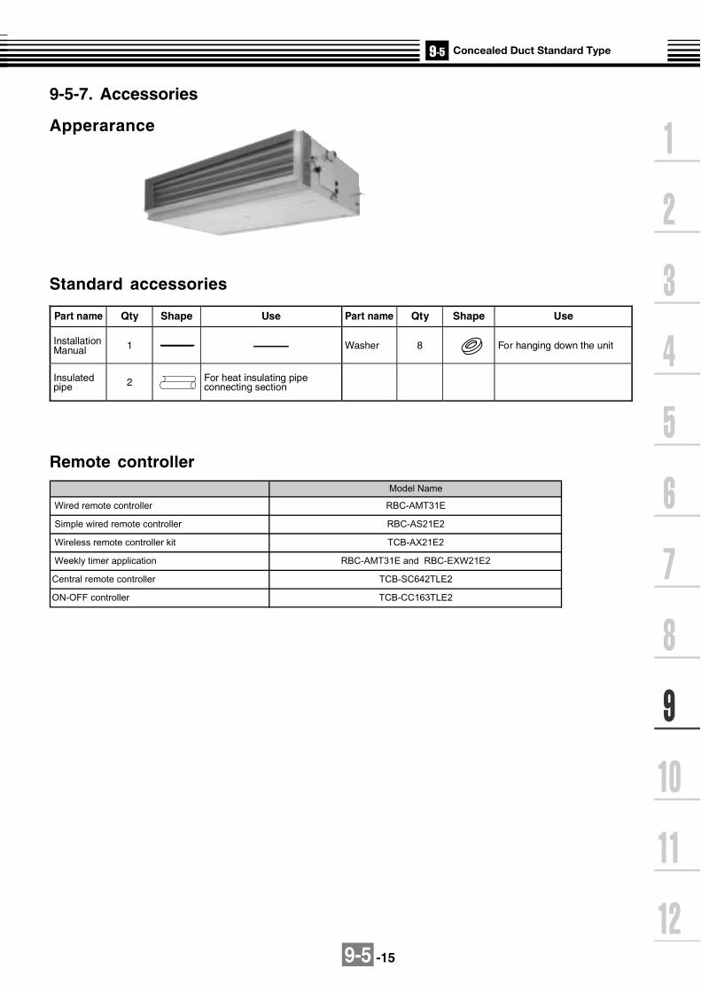
9-5 -15
9-5-7. Accessories
Apperarance
Standard accessories
Part name Qty Shape Use Part name Qty Shape Use
Installation Manual 1 Washer 8 For hanging down the unit
Insulated pipe 2 For heat insulating pipe
connecting section
Remote controller
Central remote controller TCB-SC642TLE2
ON-OFF controller TCB-CC163TLE2
Weekly timer application
Model Name
RBC-AMT31E
RBC-AS21E2
TCB-AX21E2
RBC-AMT31E and RBC-EXW21E2
Wired remote controller
Simple wired remote controller
Wireless remote controller kit

9-5 -16
Optional accessories
High Efficiency Filter 65
TCB-UFM11BFCE TCB-UFM21BFCE
High Efficiency Filter 90
TCB-UFH51BFCE TCB-UFH61BFCE
Filter Chamber
TCB-FC281BE, TCB-FC501BETCB-FC801BE, TCB-FC1401BE
Filter kit for underside
TCB-FK281BE, TCB-FK501BETCB-FK801BE, TCB-FK1401BE
Suction Canvas
TCB-CA281BE, TCB-CA501BETCB-CA801BE, TCB-CA1401BE
Ceiling panel
Standard filter and filter frame
High Efficiency Filter 65 TCB-UFM11BE TCB-UFM21BE TCB-UFM31BE TCB-UFM41BE
High Efficiency Filter 90 TCB-UFH51BE TCB-UFH61BE TCB-UFH71BE TCB-UFH81BE

9-5 -17
Name Model name Note
Dust collecting effect :65%(NBS Colorimentric method)
Dust collecting effect :90%(NBS Colorimentric method)
For high efficiency filter
Dust collecting effect :65%(NBS Colorimentric method)
Dust collecting effect :90%(NBS Colorimentric method)
Adjustment height of the suction canvas is more 40mm and 100mm
Kit of underside prefilter &shielding plate of rear suction
TCB-UFM11BFCE
TCB-UFM11BFCE(2 pcs.)
TCB-UFM21BFCE
TCB-UFM21BFCE(2 pcs.)
TCB-UFH51BFCE
TCB-UFH51BFCE(2 pcs.)
TCB-UFH61BFCE
TCB-UFH61BFCE(2 pcs.)
TCB-FC281BE
TCB-FC501BE
TCB-FC801BE
TCB-FC1401BE
TCB-UFM11BE
TCB-UFM21BE
TCB-UFM31BE
TCB-UFM41BE
TCB-UFH51BE
TCB-UFH61BE
TCB-UFH71BE
TCB-UFH81BE
RBC-UD281PE(W)
RBC-UD501PE(W)
RBC-UD801PE(W)
RBC-UD1401PE(W)
TCB-CA281BE
TCB-CA501BE
TCB-CA801BE
TCB-CA1401BE
TCB-FK281BE
TCB-FK501BE
TCB-FK801BE
TCB-FK1401BE
High Efficiency Filter 65 (For rear suction)
High Efficiency Filter 90 (For rear suction)
Filter Chamber (For rear suction)
High Efficiency Filter 65 (For underside suction)
High Efficiency Filter 90 (For underside suction)
Ceiling panel (Half panel for underside
suction)
Suction Canvas (For underside suction)
Filter kit for underside
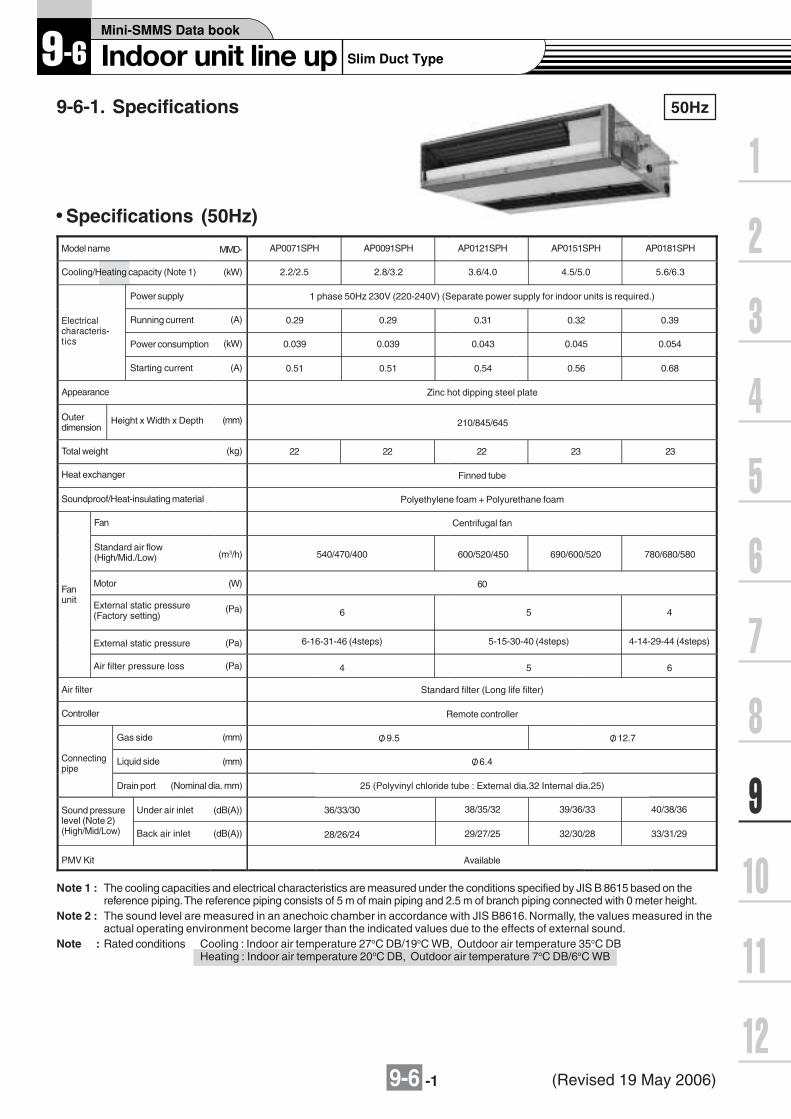
9-6 -1
9-6-1. Specifications 50Hz
Model name
Cooling/Heating capacity (Note 1)
AP0071SPH
2.2/2.5
Power supply
Electricalcharacteris-tics
Running current (A)
Power consumption
MMD-
(kW)
(kW)
1 phase 50Hz 230V (220-240V) (Separate power supply for indoor units is required.)
0.29
0.039
AP0091SPH
2.8/3.2
AP0121SPH
3.6/4.0
AP0151SPH
4.5/5.0
AP0181SPH
5.6/6.3
0.29
0.039
0.31
0.043
0.32
0.045
0.39
0.054
Note 1 : The cooling capacities and electrical characteristics are measured under the conditions specified by JIS B 8615 based on thereference piping. The reference piping consists of 5 m of main piping and 2.5 m of branch piping connected with 0 meter height.
Note 2 : The sound level are measured in an anechoic chamber in accordance with JIS B8616. Normally, the values measured in theactual operating environment become larger than the indicated values due to the effects of external sound.
Note : Rated conditions Cooling : Indoor air temperature 27oC DB/19oC WB, Outdoor air temperature 35oC DBHeating : Indoor air temperature 20oC DB, Outdoor air temperature 7oC DB/6oC WB
Specifications (50Hz)
Starting current
Appearance
Height x Width x DepthOuterdimension
Total weight
Heat exchanger
Soundproof/Heat-insulating material
Fan
Motor
External static pressure
External static pressure(Factory setting)
Air filter pressure loss
Fanunit
Air filter
Controller
Gas side
Liquid side
Drain port
Connectingpipe
(A)
(mm)
(kg)
(m3/h)
(W)
(Pa)
(Pa)
(Pa)
(mm)
(mm)
(Nominal dia. mm)
(dB(A))Sound pressurelevel (Note 2)(High/Mid/Low)
0.51
Zinc hot dipping steel plate
22
Finned tube
Polyethylene foam + Polyurethane foam
Centrifugal fan
540/470/400
60
6
4
Standard filter (Long life filter)
Remote controller
O/ 9.5
25 (Polyvinyl chloride tube : External dia.32 Internal dia.25)
36/33/30
0.51 0.54 0.56 0.68
22 22 23 23
600/520/450 690/600/520 780/680/580
5 4
5 6
O/ 12.7
O/ 6.4
38/35/32 39/36/33 40/38/36
210/845/645
28/26/24 29/27/25 32/30/28 33/31/29(dB(A))
Under air inlet
Back air inlet
PMV Kit Available
Standard air flow(High/Mid./Low)
6-16-31-46 (4steps) 5-15-30-40 (4steps) 4-14-29-44 (4steps)
(Revised 19 May 2006)

9-6 -2
60Hz
Model name
Cooling/Heating capacity (Note 1)
AP0071SPH
2.2/2.5
Power supply
Electricalcharacteris-tics
Running current (A)
Power consumption
MMD-
(kW)
(kW)
1 phase 60Hz 220V (Separate power supply for indoor units is required.)
0.27
0.037
AP0091SPH
2.8/3.2
AP0121SPH
3.6/4.0
AP0151SPH
4.5/5.0
AP0181SPH
5.6/6.3
0.27
0.037
0.30
0.041
0.31
0.043
0.37
0.052
Note 1 : The cooling capacities and electrical characteristics are measured under the conditions specified by JIS B 8615 based on thereference piping. The reference piping consists of 5 m of main piping and 2.5 m of branch piping connected with 0 meter height.
Note 2 : The sound level are measured in an anechoic chamber in accordance with JIS B8616. Normally, the values measured in theactual operating environment become larger than the indicated values due to the effects of external sound.
Note : Rated conditions Cooling : Indoor air temperature 27oC DB/19oC WB, Outdoor air temperature 35oC DBHeating : Indoor air temperature 20oC DB, Outdoor air temperature 7oC DB/6oC WB
Specifications (60Hz)
Starting current
Appearance
Height x Width x DepthOuterdimension
Total weight
Heat exchanger
Soundproof/Heat-insulating material
Fan
Standard air flow(High/Mid./Low)
Motor
External static pressure
External static pressure(Factory setting)
Air filter pressure loss
Fanunit
Air filter
Controller
Gas side
Liquid side
Drain port
Connectingpipe
(A)
(mm)
(kg)
(m3/h)
(W)
(Pa)
(Pa)
(Pa)
(mm)
(mm)
(Nominal dia. mm)
(dB(A))Sound pressurelevel (Note 2)(High/Mid/Low)
0.47
Zinc hot dipping steel plate
22
Finned tube
Polyethylene foam + Polyurethane foam
Centrifugal fan
540/470/400
60
6
4
Standard filter (Long life filter)
Remote controller
O/ 9.5
25 (Polyvinyl chloride tube : External dia.32 Internal dia.25)
36/33/30
0.47 0.53 0.54 0.65
22 22 23 23
600/520/450 690/600/520 780/680/580
5 4
5 6
O/ 12.7
O/ 6.4
38/35/32 39/36/33 40/38/36
210/845/645
28/26/24 29/27/25 32/30/28 33/31/29(dB(A))
Under air inlet
Back air inlet
PMV Kit Available
6-16-31-46 (4steps) 5-15-30-45 (4steps) 4-14-29-44 (4steps)
(Revised 07 Apr 2006)

9-6 -3
805
805
825
n=24 M5 (O/ 4.2 mounting hole)
n=22 M5 (O/ 4.2 mounting hole)
10012.5
100 100 100 100 100 10012.5
45.3
10026
6.5
12.5
170
100
41.5 8.2
or le
ss28
6.8
12.5
44.3
100
44.3
188.
6
100
825
100 100 100 100 100 100 100 100
MMD-AP0071SPH, AP0091SPH, AP0121SPH, AP0151SPH, AP0181SPH
9-6-2. Dimension
Air inlet connecting flange (Field supply)
Rearside
Wired remote controller RBC-AMT31E
Simple wired remote controller RBC-AS21E2
Wireless remote controller kit TCB-AX21E2
Weekly timer application RBC-AMT31E and RBC-EXW21E2
845
80580
Fresh air inlet(Knock-out hole)
59 910
168
(insi
de)
2120
19
67
210
5751
164
567
359
40
372
422
502
4-O /
4
O/92 80 16
812
021 803 (inside) Refrigerant piping2121
Air filter 103
31
33163
Hanger plate
Drain-up port
Underside

9-6 -4
MMD-AP007SPH-C, AP0091SPH-C, AP0121SPH-C, AP0151SPH-C, AP0181SPH-C,
MMD-AP0071SH-C, AP0091SH-C, AP0121SH-C, AP0151SH-C, AP0181SH-C
805
805
825
n=24 M5 (O/ 4.2 mounting hole)
n=22 M5 (O/ 4.2 mounting hole)
10012.5
100 100 100 100 100 10012.5
45.3
10026
6.5
12.5
170
100
41.5 8.2
or le
ss28
6.8
12.5
44.3
100
44.3
188.
6
100
825
100 100 100 100 100 100 100 100
Air inlet connecting flange (Field supply)
Rearside
Underside
Wired remote controller RBC-AMT31E
Simple wired remote controller RBC-AS21E2
Wireless remote controller kit TCB-AX21E2
Weekly timer application RBC-AMT31E and RBC-EXW21E2
845
80580
Fresh air inlet(Knock-out hole)
59 910
168
(insi
de)
2120
19
67
210
5751
164
5
67
359
40
372
422
502
4-O /
4
O/ 92
80 168
146
120
21 21 803 (inside)Refrigerant piping
21Natural drain port 103
31
33163
Hanger plate
Drain-up port(SPH model only)
*China only
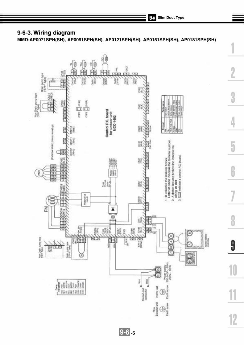
9-6 -5
9-6-3. Wiring diagramMMD-AP0071SPH(SH), AP0091SPH(SH), AP0121SPH(SH), AP0151SPH(SH), AP0181SPH(SH)
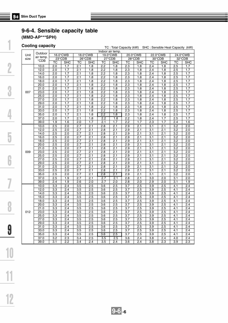
9-6 -6
TC : Total Capacity (kW) SHC : Sensible Heat Capacity (kW)Indoor air temp.
Unit Outdoor 16.0°CWB 18.0°CWB 19.0°CWB 20.0°CWB 22.0°CWB 24.0°CWBsize air temp. 23°CDB 26°CDB 27°CDB 28°CDB 30°CDB 32°CDB
°CDB TC SHC TC SHC TC SHC TC SHC TC SHC TC SHC10.0 2.0 1.7 2.1 1.8 2.2 1.8 2.3 1.8 2.4 1.8 2.5 1.712.0 2.0 1.7 2.1 1.8 2.2 1.8 2.3 1.8 2.4 1.8 2.5 1.714.0 2.0 1.7 2.1 1.8 2.2 1.8 2.3 1.8 2.4 1.8 2.5 1.716.0 2.0 1.7 2.1 1.8 2.2 1.8 2.3 1.8 2.4 1.8 2.5 1.718.0 2.0 1.7 2.1 1.8 2.2 1.8 2.3 1.8 2.4 1.8 2.5 1.720.0 2.0 1.7 2.1 1.8 2.2 1.8 2.3 1.8 2.4 1.8 2.5 1.721.0 2.0 1.7 2.1 1.8 2.2 1.8 2.3 1.8 2.4 1.8 2.5 1.7
007 23.0 2.0 1.7 2.1 1.8 2.2 1.8 2.3 1.8 2.4 1.8 2.5 1.725.0 2.0 1.7 2.1 1.8 2.2 1.8 2.3 1.8 2.4 1.8 2.5 1.727.0 2.0 1.7 2.1 1.8 2.2 1.8 2.3 1.8 2.4 1.8 2.5 1.729.0 2.0 1.7 2.1 1.8 2.2 1.8 2.3 1.8 2.4 1.8 2.5 1.731.0 2.0 1.7 2.1 1.8 2.2 1.8 2.3 1.8 2.4 1.8 2.5 1.733.0 2.0 1.7 2.1 1.8 2.2 1.8 2.3 1.8 2.4 1.8 2.5 1.735.0 2.0 1.7 2.1 1.8 2.2 1.8 2.3 1.8 2.4 1.8 2.5 1.737.0 2.0 1.7 2.1 1.8 2.2 1.8 2.2 1.8 2.4 1.7 2.5 1.739.0 1.9 1.6 2.0 1.7 2.1 1.7 2.2 1.7 2.3 1.7 2.4 1.610.0 2.5 2.0 2.7 2.1 2.8 2.1 2.9 2.1 3.1 2.1 3.2 2.012.0 2.5 2.0 2.7 2.1 2.8 2.1 2.9 2.1 3.1 2.1 3.2 2.014.0 2.5 2.0 2.7 2.1 2.8 2.1 2.9 2.1 3.1 2.1 3.2 2.016.0 2.5 2.0 2.7 2.1 2.8 2.1 2.9 2.1 3.1 2.1 3.2 2.018.0 2.5 2.0 2.7 2.1 2.8 2.1 2.9 2.1 3.1 2.1 3.2 2.020.0 2.5 2.0 2.7 2.1 2.8 2.1 2.9 2.1 3.1 2.1 3.2 2.021.0 2.5 2.0 2.7 2.1 2.8 2.1 2.9 2.1 3.1 2.1 3.2 2.0
009 23.0 2.5 2.0 2.7 2.1 2.8 2.1 2.9 2.1 3.1 2.1 3.2 2.025.0 2.5 2.0 2.7 2.1 2.8 2.1 2.9 2.1 3.1 2.1 3.2 2.027.0 2.5 2.0 2.7 2.1 2.8 2.1 2.9 2.1 3.1 2.1 3.2 2.029.0 2.5 2.0 2.7 2.1 2.8 2.1 2.9 2.1 3.1 2.1 3.2 2.031.0 2.5 2.0 2.7 2.1 2.8 2.1 2.9 2.1 3.1 2.1 3.2 2.033.0 2.5 2.0 2.7 2.1 2.8 2.1 2.9 2.1 3.1 2.1 3.2 2.035.0 2.5 2.0 2.7 2.1 2.8 2.1 2.9 2.1 3.1 2.1 3.2 2.037.0 2.5 1.9 2.7 2.1 2.7 2.1 2.8 2.1 3.0 2.0 3.1 2.039.0 2.4 1.9 2.6 2.0 2.7 2.0 2.8 2.0 2.9 2.0 3.1 1.910.0 3.3 2.4 3.5 2.5 3.6 2.5 3.7 2.5 3.9 2.5 4.1 2.412.0 3.3 2.4 3.5 2.5 3.6 2.5 3.7 2.5 3.9 2.5 4.1 2.414.0 3.3 2.4 3.5 2.5 3.6 2.5 3.7 2.5 3.9 2.5 4.1 2.416.0 3.3 2.4 3.5 2.5 3.6 2.5 3.7 2.5 3.9 2.5 4.1 2.418.0 3.3 2.4 3.5 2.5 3.6 2.5 3.7 2.5 3.9 2.5 4.1 2.420.0 3.3 2.4 3.5 2.5 3.6 2.5 3.7 2.5 3.9 2.5 4.1 2.421.0 3.3 2.4 3.5 2.5 3.6 2.5 3.7 2.5 3.9 2.5 4.1 2.4
012 23.0 3.3 2.4 3.5 2.5 3.6 2.5 3.7 2.5 3.9 2.5 4.1 2.425.0 3.3 2.4 3.5 2.5 3.6 2.5 3.7 2.5 3.9 2.5 4.1 2.427.0 3.3 2.4 3.5 2.5 3.6 2.5 3.7 2.5 3.9 2.5 4.1 2.429.0 3.3 2.4 3.5 2.5 3.6 2.5 3.7 2.5 3.9 2.5 4.1 2.431.0 3.3 2.4 3.5 2.5 3.6 2.5 3.7 2.5 3.9 2.5 4.1 2.433.0 3.3 2.4 3.5 2.5 3.6 2.5 3.7 2.5 3.9 2.5 4.1 2.435.0 3.3 2.4 3.5 2.5 3.6 2.5 3.7 2.5 3.9 2.5 4.1 2.437.0 3.2 2.3 3.4 2.5 3.5 2.5 3.6 2.4 3.8 2.4 4.0 2.439.0 3.1 2.2 3.4 2.4 3.5 2.4 3.6 2.4 3.8 2.3 3.9 2.3
9-6-4. Sensible capacity table(MMD-AP***SPH)
Cooling capacity

9-6 -7
Cooling capacity (cont.)Indoor air temp.
Unit Outdoor 16.0°CWB 18.0°CWB 19.0°CWB 20.0°CWB 22.0°CWB 24.0°CWBsize air temp. 23°CDB 26°CDB 27°CDB 28°CDB 30°CDB 32°CDB
°CDB TC SHC TC SHC TC SHC TC SHC TC SHC TC SHC10.0 4.1 3.0 4.4 3.2 4.5 3.2 4.6 3.2 4.9 3.2 5.1 3.112.0 4.1 3.0 4.4 3.2 4.5 3.2 4.6 3.2 4.9 3.2 5.1 3.114.0 4.1 3.0 4.4 3.2 4.5 3.2 4.6 3.2 4.9 3.2 5.1 3.116.0 4.1 3.0 4.4 3.2 4.5 3.2 4.6 3.2 4.9 3.2 5.1 3.118.0 4.1 3.0 4.4 3.2 4.5 3.2 4.6 3.2 4.9 3.2 5.1 3.120.0 4.1 3.0 4.4 3.2 4.5 3.2 4.6 3.2 4.9 3.2 5.1 3.121.0 4.1 3.0 4.4 3.2 4.5 3.2 4.6 3.2 4.9 3.2 5.1 3.1
015 23.0 4.1 3.0 4.4 3.2 4.5 3.2 4.6 3.2 4.9 3.2 5.1 3.125.0 4.1 3.0 4.4 3.2 4.5 3.2 4.6 3.2 4.9 3.2 5.1 3.127.0 4.1 3.0 4.4 3.2 4.5 3.2 4.6 3.2 4.9 3.2 5.1 3.129.0 4.1 3.0 4.4 3.2 4.5 3.2 4.6 3.2 4.9 3.2 5.1 3.131.0 4.1 3.0 4.4 3.2 4.5 3.2 4.6 3.2 4.9 3.2 5.1 3.133.0 4.1 3.0 4.4 3.2 4.5 3.2 4.6 3.2 4.9 3.2 5.1 3.135.0 4.1 3.0 4.4 3.2 4.5 3.2 4.6 3.2 4.9 3.2 5.1 3.137.0 4.0 3.0 4.3 3.1 4.4 3.1 4.5 3.1 4.8 3.1 5.0 3.039.0 3.9 2.8 4.2 3.0 4.3 3.0 4.4 3.0 4.7 3.0 4.9 2.910.0 5.1 3.7 5.4 3.9 5.6 3.9 5.8 3.9 6.1 3.9 6.4 3.812.0 5.1 3.7 5.4 3.9 5.6 3.9 5.8 3.9 6.1 3.9 6.4 3.814.0 5.1 3.7 5.4 3.9 5.6 3.9 5.8 3.9 6.1 3.9 6.4 3.816.0 5.1 3.7 5.4 3.9 5.6 3.9 5.8 3.9 6.1 3.9 6.4 3.818.0 5.1 3.7 5.4 3.9 5.6 3.9 5.8 3.9 6.1 3.9 6.4 3.820.0 5.1 3.7 5.4 3.9 5.6 3.9 5.8 3.9 6.1 3.9 6.4 3.821.0 5.1 3.7 5.4 3.9 5.6 3.9 5.8 3.9 6.1 3.9 6.4 3.8
018 23.0 5.1 3.7 5.4 3.9 5.6 3.9 5.8 3.9 6.1 3.9 6.4 3.825.0 5.1 3.7 5.4 3.9 5.6 3.9 5.8 3.9 6.1 3.9 6.4 3.827.0 5.1 3.7 5.4 3.9 5.6 3.9 5.8 3.9 6.1 3.9 6.4 3.829.0 5.1 3.7 5.4 3.9 5.6 3.9 5.8 3.9 6.1 3.9 6.4 3.831.0 5.1 3.7 5.4 3.9 5.6 3.9 5.8 3.9 6.1 3.9 6.4 3.833.0 5.1 3.7 5.4 3.9 5.6 3.9 5.8 3.9 6.1 3.9 6.4 3.835.0 5.1 3.7 5.4 3.9 5.6 3.9 5.8 3.9 6.1 3.9 6.4 3.837.0 5.0 3.6 5.3 3.8 5.5 3.8 5.7 3.8 6.0 3.8 6.3 3.739.0 4.9 3.5 5.2 3.7 5.4 3.7 5.5 3.7 5.9 3.6 6.1 3.6

9-6 -8
SHC : Sensible Heat Capacity (kW)
Unit Outdoor Indoor air temp. °CDB
size air temp. 16.0 18.0 20.0 22.0 24.0
°CWB SHC SHC SHC SHC SHC-15.0 1.6 1.5 1.5 1.5 1.4-13.0 1.7 1.6 1.6 1.6 1.5-11.0 1.8 1.7 1.7 1.7 1.6-10.0 1.8 1.8 1.8 1.7 1.7-8.0 1.9 1.9 1.9 1.8 1.8-6.0 2.0 2.0 2.0 1.9 1.9-4.0 2.1 2.1 2.0 2.0 1.9
007 -2.0 2.2 2.2 2.1 2.1 2.00.0 2.3 2.3 2.2 2.2 2.12.0 2.4 2.4 2.3 2.3 2.24.0 2.5 2.5 2.4 2.4 2.36.0 2.6 2.6 2.5 2.4 2.48.0 2.6 2.6 2.5 2.4 2.4
10.0 2.6 2.6 2.5 2.4 2.412.0 2.6 2.6 2.5 2.4 2.414.0 2.6 2.6 2.5 2.4 2.4-15.0 2.0 2.0 1.9 1.9 1.8-13.0 2.1 2.1 2.1 2.0 1.9-11.0 2.3 2.2 2.2 2.1 2.1-10.0 2.3 2.3 2.2 2.2 2.1-8.0 2.5 2.4 2.4 2.3 2.3-6.0 2.6 2.6 2.5 2.4 2.4-4.0 2.7 2.7 2.6 2.6 2.5
009 -2.0 2.9 2.8 2.7 2.7 2.60.0 3.0 2.9 2.9 2.8 2.72.0 3.1 3.0 3.0 2.9 2.84.0 3.2 3.2 3.1 3.0 2.96.0 3.3 3.3 3.2 3.1 3.08.0 3.3 3.3 3.2 3.1 3.0
10.0 3.3 3.3 3.2 3.1 3.012.0 3.3 3.3 3.2 3.1 3.014.0 3.3 3.3 3.2 3.1 3.0-15.0 2.5 2.5 2.4 2.3 2.3-13.0 2.7 2.6 2.6 2.5 2.4-11.0 2.8 2.8 2.7 2.7 2.6-10.0 2.9 2.9 2.8 2.7 2.7-8.0 3.1 3.0 3.0 2.9 2.8-6.0 3.3 3.2 3.1 3.0 3.0-4.0 3.4 3.3 3.3 3.2 3.1
012 -2.0 3.6 3.5 3.4 3.3 3.30.0 3.7 3.7 3.6 3.5 3.42.0 3.9 3.8 3.7 3.6 3.54.0 4.0 3.9 3.9 3.8 3.76.0 4.2 4.1 4.0 3.9 3.88.0 4.2 4.1 4.0 3.9 3.8
10.0 4.2 4.1 4.0 3.9 3.812.0 4.2 4.1 4.0 3.9 3.814.0 4.2 4.1 4.0 3.9 3.8
Heating capacity

9-6 -9
UnitOutdoor Indoor air temp. °CDB
size air temp. 16.0 18.0 20.0 22.0 24.0
°CWB SHC SHC SHC SHC SHC-15.0 3.1 3.1 3.0 2.9 2.9-13.0 3.3 3.3 3.2 3.1 3.0-11.0 3.6 3.5 3.4 3.3 3.2-10.0 3.7 3.6 3.5 3.4 3.3-8.0 3.9 3.8 3.7 3.6 3.5-6.0 4.1 4.0 3.9 3.8 3.7-4.0 4.3 4.2 4.1 4.0 3.9
015 -2.0 4.5 4.4 4.3 4.2 4.10.0 4.7 4.6 4.5 4.4 4.22.0 4.8 4.7 4.6 4.5 4.44.0 5.0 4.9 4.8 4.7 4.66.0 5.2 5.1 5.0 4.9 4.88.0 5.2 5.1 5.0 4.9 4.8
10.0 5.2 5.1 5.0 4.9 4.812.0 5.2 5.1 5.0 4.9 4.814.0 5.2 5.1 5.0 4.9 4.8-15.0 3.9 3.9 3.8 3.7 3.6-13.0 4.2 4.1 4.0 3.9 3.8-11.0 4.5 4.4 4.3 4.2 4.1-10.0 4.6 4.5 4.4 4.3 4.2-8.0 4.9 4.8 4.7 4.6 4.4-6.0 5.1 5.0 4.9 4.8 4.7-4.0 5.4 5.3 5.2 5.0 4.9
018 -2.0 5.6 5.5 5.4 5.3 5.10.0 5.9 5.8 5.6 5.5 5.32.0 6.1 6.0 5.9 5.7 5.64.0 6.3 6.2 6.1 5.9 5.86.0 6.6 6.4 6.3 6.1 6.08.0 6.6 6.4 6.3 6.1 6.0
10.0 6.6 6.4 6.3 6.1 6.012.0 6.6 6.4 6.3 6.1 6.014.0 6.6 6.4 6.3 6.1 6.0
Heating capacity (cont.)

9-6 -10
9-6-5. Fan characteristics
0
10
20
30
40
50
60
300 400 500 600 700
Air Volume (m3/h)
Ext
erna
l sta
tic p
ress
ure
(Pa)
High (50Pa)
High (35Pa)
High (20Pa)
High (10Pa)
Low (50Pa)
Low (35Pa)
Low (20Pa)
Lower limit of externalstatic pressure (50Pa)
Lower limit of externalstatic pressure (35Pa)
Lower limit of externalstatic pressure (20Pa)
Upper limit ofexternal static
pressure(35Pa)
Upper limit of externalstatic pressure(50Pa)
Upper limit ofexternal static
pressure(20Pa)
Upper limit ofexternal static
pressure(10Pa)
Standard air volume : 540m3/h
Low (10Pa)
MMD-AP0071SPHMMD-AP0091SPH
MMD-AP0121SPH
MMD-AP0151SPH MMD-AP0181SPH
0
10
20
30
40
50
60
300 400 500 600 700
Air Volume (m3/h)
Ext
erna
l sta
tic p
ress
ure
(Pa)
High (50Pa)
High (35Pa)
High (20Pa)
High (10Pa)
Low (50Pa)
Low (35Pa)
Low (20Pa)
Low (10Pa)
Lower limit of externalstatic pressure (50Pa)
Lower limit of externalstatic pressure (35Pa)
Lower limit of externalstatic pressure (20Pa)
Upper limit of externalstatic pressure(50Pa)
Upper limit ofexternal static
pressure(20Pa)
Upper limit ofexternal static
pressure(35Pa)
Upper limit ofexternal static
pressure(10Pa)
Standard air volume : 600m3/h
0
10
20
30
40
50
60
400 500 600 700 800 900
High (50Pa)
High (35Pa)
High (20Pa)
Low (50Pa)
Low (35Pa)
Low (20Pa)
Low (10Pa)
Lower limit ofexternal staticpressure (50Pa)
Lower limit ofexternal staticpressure (35Pa)
Lower limit ofexternal staticpressure (20Pa)
Upper limit of externalstatic pressure(50Pa)
Upper limit ofexternal static
pressure(20Pa)
Upper limit ofexternal static
pressure(35Pa)
Upper limit ofexternal static
pressure(10Pa)
High (10Pa)
Standard air volume : 780m3/h
Air Volume (m3/h)
Ext
erna
l sta
tic p
ress
ure
(Pa)
0
10
20
30
40
50
60
400 500 600 700 800
High (50Pa)
High (35Pa)
High (20Pa)
High (10Pa)
Low (50Pa)
Low (35Pa)
Low (20Pa)
Low (10Pa)
Lower limit of externalstatic pressure (50Pa)
Lower limit of externalstatic pressure (35Pa)
Lower limit of externalstatic pressure (20Pa)
Upper limit of externalstatic pressure(50Pa)
Upper limit ofexternal static
pressure(20Pa)
Upper limit ofexternal static
pressure(35Pa)
Upper limit ofexternal static
pressure(10Pa)
Air Volume (m3/h)
Ext
erna
l sta
tic p
ress
ure
(Pa)
Standard air volume : 690m3/h
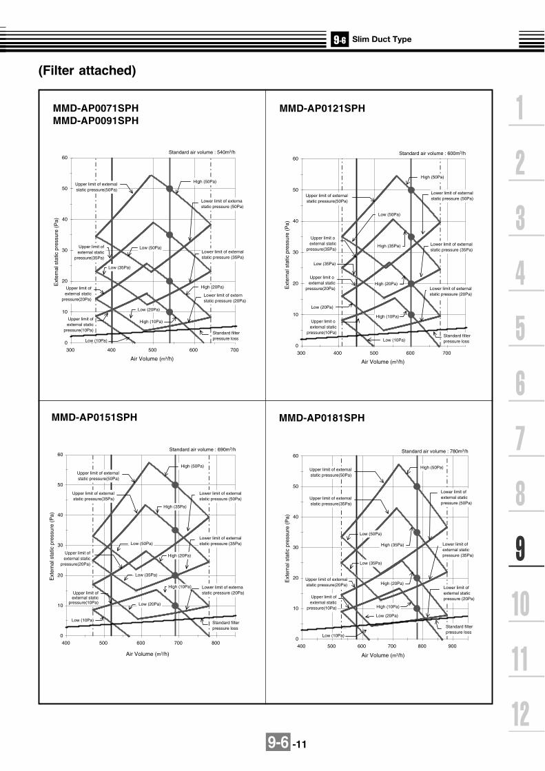
9-6 -11
0
10
20
30
40
50
60
400 500 600 700 800
High (50Pa)
High (35Pa)
High (10Pa)
Low (50Pa)
Low (35Pa)
Low (20Pa)
Low (10Pa)
Lower limit of externalstatic pressure (35Pa)
Lower limit of externastatic pressure (20Pa)
Upper limit of externalstatic pressure(50Pa)
Upper limit ofexternal static
pressure(20Pa)
Upper limit of externalstatic pressure(35Pa)
Upper limit ofexternal static
pressure(10Pa)
Standard filterpressure loss
High (20Pa)
Lower limit of externalstatic pressure (50Pa)
Standard air volume : 690m3/h
Air Volume (m3/h)
Ext
erna
l sta
tic p
ress
ure
(Pa)
(Filter attached)
MMD-AP0071SPHMMD-AP0091SPH
MMD-AP0121SPH
MMD-AP0151SPH MMD-AP0181SPH
0
10
20
30
40
50
60
300 400 500 600 700
High (50Pa)
High (20Pa)
High (10Pa)
Low (50Pa)
Low (35Pa)
Low (20Pa)
Lower limit of externastatic pressure (50Pa)
Lower limit of externalstatic pressure (35Pa)
Lower limit of externstatic pressure (20Pa)
Upper limit of externalstatic pressure(50Pa)
Upper limit ofexternal static
pressure(20Pa)
Upper limit of external static
pressure(35Pa)
Upper limit ofexternal static
pressure(10Pa)Standard filterpressure loss
Air Volume (m3/h)
Ext
erna
l sta
tic p
ress
ure
(Pa)
Standard air volume : 540m3/h
Low (10Pa)0
10
20
30
40
50
60
300 400 500 600 700
High (50Pa)
High (35Pa)
High (20Pa)
High (10Pa)
Low (50Pa)
Low (35Pa)
Low (20Pa)
Low (10Pa)
Lower limit of externalstatic pressure (50Pa)
Lower limit of externalstatic pressure (35Pa)
Lower limit of externalstatic pressure (20Pa)
Upper limit of externalstatic pressure(50Pa)
Upper limit oexternal static
pressure(20Pa)
Upper limit oexternal static
pressure(35Pa)
Upper limit oexternal static
pressure(10Pa)Standard filterpressure loss
Air Volume (m3/h)
Ext
erna
l sta
tic p
ress
ure
(Pa)
Standard air volume : 600m3/h
0
10
20
30
40
50
60
400 500 600 700 800 900
High (50Pa)
High (35Pa)
High (20Pa)
High (10Pa)
Low (50Pa)
Low (35Pa)
Low (20Pa)
Low (10Pa)
Lower limit ofexternal staticpressure (50Pa)
Lower limit ofexternal staticpressure (35Pa)
Upper limit of externalstatic pressure(50Pa)
Upper limit of externalstatic pressure(20Pa)
Upper limit of externalstatic pressure(35Pa)
Upper limit ofexternal static
pressure(10Pa)
Lower limit ofexternal staticpressure (20Pa)
Standard filterpressure loss
Air Volume (m3/h)
Ext
erna
l sta
tic p
ress
ure
(Pa)
Standard air volume : 780m3/h
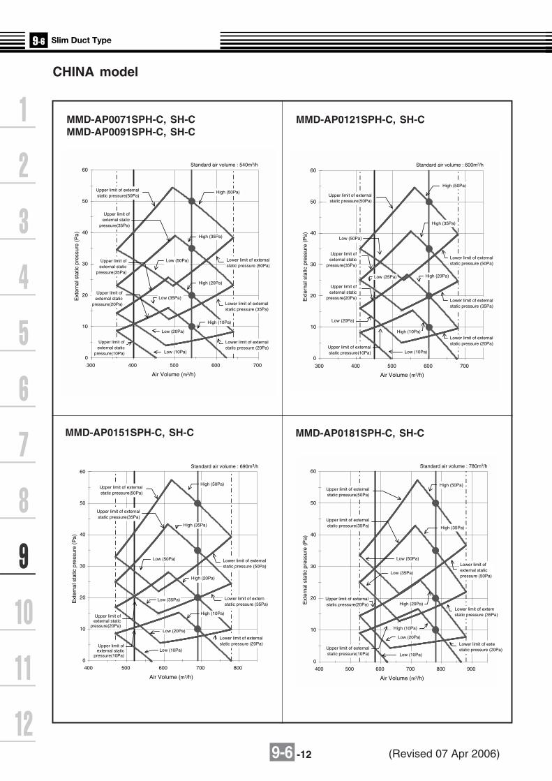
9-6 -12
CHINA model
MMD-AP0071SPH-C, SH-CMMD-AP0091SPH-C, SH-C
MMD-AP0121SPH-C, SH-C
MMD-AP0151SPH-C, SH-C MMD-AP0181SPH-C, SH-C
0
10
20
30
40
50
60
300 400 500 600 700
High (50Pa)
High (35Pa)
High (20Pa)
High (10Pa)
Low (50Pa)
Low (35Pa)
Low (20Pa)
Lower limit of externalstatic pressure (50Pa)
Lower limit of externalstatic pressure (35Pa)
Lower limit of externalstatic pressure (20Pa)
Upper limit ofexternal static
pressure(35Pa)
Upper limit of externalstatic pressure(50Pa)
Upper limit ofexternal static
pressure(35Pa)
Upper limit ofexternal static
pressure(10Pa)
Air Volume (m3/h)
Ext
erna
l sta
tic p
ress
ure
(Pa)
Standard air volume : 540m3/h
Low (10Pa)
Upper limit ofexternal static
pressure(20Pa)
0
10
20
30
40
50
60
300 400 500 600 700
High (50Pa)
High (35Pa)
High (20Pa)
High (10Pa)
Low (50Pa)
Low (35Pa)
Low (20Pa)
Low (10Pa)
Upper limit of externalstatic pressure(50Pa)
Upper limit ofexternal static
pressure(20Pa)
Upper limit ofexternal static
pressure(35Pa)
Upper limit of externalstatic pressure(10Pa)
Air Volume (m3/h)
Ext
erna
l sta
tic p
ress
ure
(Pa)
Standard air volume : 600m3/h
Lower limit of externalstatic pressure (50Pa)
Lower limit of externalstatic pressure (35Pa)
Lower limit of externalstatic pressure (20Pa)
0
10
20
30
40
50
60
400 500 600 700 800
High (50Pa)
High (35Pa)
High (20Pa)
High (10Pa)
Low (50Pa)
Low (35Pa)
Low (20Pa)
Low (10Pa)
Upper limit of externalstatic pressure(50Pa)
Upper limit ofexternal static
pressure(20Pa)
Upper limit of externalstatic pressure(35Pa)
Upper limit of external static
pressure(10Pa)
Air Volume (m3/h)
Ext
erna
l sta
tic p
ress
ure
(Pa)
Standard air volume : 690m3/h
Lower limit of externalstatic pressure (50Pa)
Lower limit of externstatic pressure (35Pa)
Lower limit of externalstatic pressure (20Pa)
0
10
20
30
40
50
60
400 500 600 700 800 900
High (50Pa)
High (35Pa)
High (20Pa)
High (10Pa)
Low (50Pa)
Low (35Pa)
Low (20Pa)
Low (10Pa)
Lower limit of externstatic pressure (35Pa)
Upper limit of externalstatic pressure(50Pa)
Upper limit of externalstatic pressure(20Pa)
Upper limit of externalstatic pressure(35Pa)
Upper limit of externalstatic pressure(10Pa)
Air Volume (m3/h)
Ext
erna
l sta
tic p
ress
ure
(Pa)
Standard air volume : 780m3/h
Lower limit ofexternal staticpressure (50Pa)
Lower limit of extestatic pressure (20Pa)
(Revised 07 Apr 2006)

9-6 -13
9-6-6. Sound characteristics (NC-Curve)MMD-AP0071SPH/SH ,MMD-AP0091SPH/SH
Air outlet Air inlet
2m 1m
Duct Duct
Center1.5m
Microphone
Measuring location
Rear air intake
External static pressure 10Pa External static pressure 20Pa
10
20
30
40
50
60
70
63 125 250 500 1000 2000 4000 8000
L
HM
NC-50
NC-40
NC-30
NC-20
Octave band center frequency (Hz)
Oct
ave
band
sou
nd p
ress
ure
leve
l (dB
)
hearing for continuous noiseApproximate threshold of
10
20
30
40
50
60
70
63 125 250 500 1000 2000 4000 8000
L
HM
NC-50
NC-40
NC-30
NC-20
Octave band center frequency (Hz)
Oct
ave
band
sou
nd p
ress
ure
leve
l (dB
)
hearing for continuous noiseApproximate threshold of
External static pressure 35Pa External static pressure 50Pa
10
20
30
40
50
60
70
63 125 250 500 1000 2000 4000 8000
NC-50
NC-40
NC-30
NC-20L
H
M
Octave band center frequency (Hz)
Oct
ave
band
sou
nd p
ress
ure
leve
l (dB
)
hearing for continuous noiseApproximate threshold of
10
20
30
40
50
60
70
63 125 250 500 1000 2000 4000 8000
L
HM
NC-50
NC-40
NC-30
NC-20
Octave band center frequency (Hz)
Oct
ave
band
sou
nd p
ress
ure
leve
l (dB
)
hearing for continuous noiseApproximate threshold of
Fan tapSound pressure
level (dB(A))
H M L
28 26 24
Fan tapSound pressure
level (dB(A))
H M L
29 27 25
Fan tapSound pressure
level (dB(A))
H M L
30 28 26
Fan tapSound pressure
level (dB(A))
H M L
32 29 27

9-6 -14
MMD-AP0121SPH/SH
Measuring location
Rear air intakeAir outlet Air inlet
2m 1m
Duct Duct
Center1.5m
Microphone
10
20
30
40
50
60
70
63 125 250 500 1000 2000 4000 8000
L
H
M
NC-50
NC-40
NC-30
NC-20
Octave band center frequency (Hz)
Oct
ave
band
sou
nd p
ress
ure
leve
l (dB
)
hearing for continuous noiseApproximate threshold of
10
20
30
40
50
60
70
63 125 250 500 1000 2000 4000 8000
Octave band center frequency (Hz)
Oct
ave
band
sou
nd p
ress
ure
leve
l (dB
)
L
H
M
NC-50
NC-40
NC-30
NC-20
hearing for continuous noiseApproximate threshold of
10
20
30
40
50
60
70
63 125 250 500 1000 2000 4000 8000
Octave band center frequency (Hz)
Oct
ave
band
sou
nd p
ress
ure
leve
l (dB
)
NC-50
NC-40
NC-30
NC-20
L
H
M
hearing for continuous noiseApproximate threshold of
10
20
30
40
50
60
70
63 125 250 500 1000 2000 4000 8000
Octave band center frequency (Hz)
Oct
ave
band
sou
nd p
ress
ure
leve
l (dB
)
L
H
M
NC-50
NC-40
NC-30
NC-20
hearing for continuous noiseApproximate threshold of
External static pressure 10Pa External static pressure 20Pa
External static pressure 35Pa External static pressure 50Pa
Fan tapSound pressure
level (dB(A))
H M L
29 27 25
Fan tapSound pressure
level (dB(A))
H M L
30 28 26
Fan tapSound pressure
level (dB(A))
H M L
31 29 27
Fan tapSound pressure
level (dB(A))
H M L
32 30 28

9-6 -15
10
20
30
40
50
60
70
63 125 250 500 1000 2000 4000 8000
Octave band center frequency (Hz)
Oct
ave
band
sou
nd p
ress
ur le
vel (
dB)
NC-50
NC-40
NC-30
NC-20
L
H
M
Approximate threshold ofhearing for continuous noise
10
20
30
40
50
60
70
63 125 250 500 1000 2000 4000 8000
Octave band center frequency (Hz)
Oct
ave
band
sou
nd p
ress
ure
leve
l (dB
)
L
H
M
NC-50
NC-40
NC-30
NC-20
Approximate threshold ofhearing for continuous noise
Measuring location
Rear air intakeAir outlet Air inlet
2m 1m
Duct Duct
Center1.5m
Microphone
L
10
20
30
40
50
60
70
63 125 250 500 1000 2000 4000 8000
Octave band center frequency (Hz)
Oct
ave
band
sou
nd p
ress
ure
leve
l (dB
)
H
M
NC-50
NC-40
NC-30
NC-20
Approximate threshold ofhearing for continuous noise
10
20
30
40
50
60
70
63 125 250 500 1000 2000 4000 8000
Octave band center frequency (Hz)
Oct
ave
band
sou
nd p
ress
ure
leve
l (dB
)
L
H
M
NC-50
NC-40
NC-30
NC-20
Approximate threshold ofhearing for continuous noise
MMD-AP0151SPH/SH
External static pressure 10Pa External static pressure 20Pa
External static pressure 35Pa External static pressure 50Pa
Fan tapSound pressure
level (dB(A))
H M L
32 30 28
Fan tapSound pressure
level (dB(A))
H M L
33 31 29
Fan tapSound pressure
level (dB(A))
H M L
34 32 30
Fan tapSound pressure
level (dB(A))
H M L
35 33 31

9-6 -16
10
20
30
40
50
60
70
63 125 250 500 1000 2000 4000 8000
Octave band center frequency (Hz)
Oct
ave
band
sou
nd p
ress
ure
leve
l (dB
)
Approximate threshold ofhearing for continuous noise
L
H
M
NC-50
NC-40
NC-30
NC-20
MMD-AP0181SPH/SH
Measuring location
Rear air intake
Air outlet Air inlet
2m 1m
Duct Duct
Center1.5m
Microphone
10
20
30
40
50
60
70
63 125 250 500 1000 2000 4000 8000
Octave band center frequency (Hz)
Oct
ave
band
sou
nd p
ress
ure
leve
l (dB
)
L
H
M
NC-50
NC-40
NC-30
NC-20Approximate threshold ofhearing for continuous noise
10
20
30
40
50
60
70
63 125 250 500 1000 2000 4000 8000
Octave band center frequency (Hz)
Oct
ave
band
sou
nd p
ress
ure
leve
l (dB
)
L
HM
NC-50
NC-40
NC-30
NC-20
hearing for continuous noiseApproximate threshold of
10
20
30
40
50
60
70
63 125 250 500 1000 2000 4000 8000
Octave band center fequency (Hz)
Oct
ave
band
sou
nd p
ress
ure
leve
l (dB
)
NC-50
NC-40
NC-30
NC-20
Approximate threshold ofhearing for continuous noise
L
H
M
External static pressure 10Pa External static pressure 20Pa
External static pressure 35Pa External static pressure 50Pa
Fan tapSound pressure
level (dB(A))
H M L
33 31 29
Fan tapSound pressure
level (dB(A))
H M L
34 32 30
Fan tapSound pressure
level (dB(A))
H M L
35 33 31
Fan tapSound pressure
level (dB(A))
H M L
36 34 32
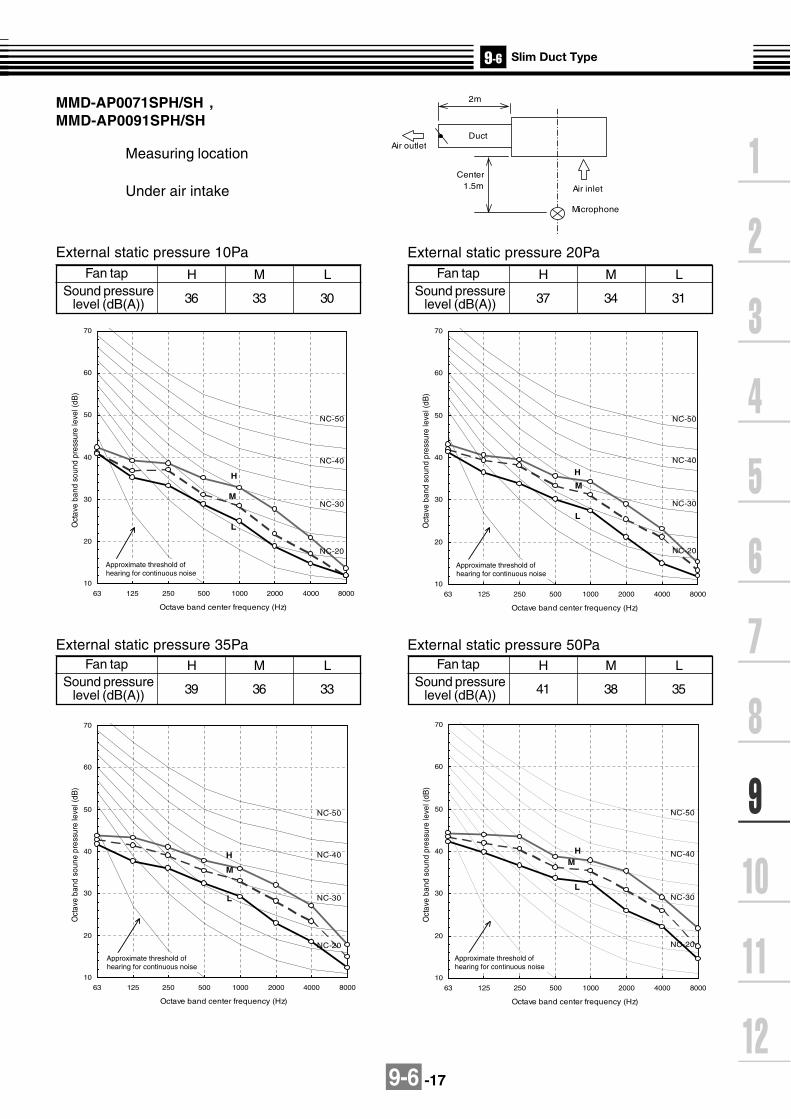
9-6 -17
10
20
30
40
50
60
70
63 125 250 500 1000 2000 4000 8000
Octave band center frequency (Hz)
Oct
ave
band
sou
nd p
ress
ure
leve
l (dB
)
L
H
M
NC-50
NC-40
NC-30
NC-20
hearing for continuous noiseApproximate threshold of
Measuring location
Under air intake
10
20
30
40
50
60
70
63 125 250 500 1000 2000 4000 8000
Octave band center frequency (Hz)
Oct
ave
band
sou
nd p
ress
ure
leve
l (dB
)
L
H
M
NC-50
NC-40
NC-30
NC-20
hearing for continuous noiseApproximate threshold of
10
20
30
40
50
60
70
63 125 250 500 1000 2000 4000 8000
Octave band center frequency (Hz)
Oct
ave
band
sou
ne p
ress
ure
leve
l (dB
)
NC-50
NC-40
NC-30
NC-20
L
H
M
hearing for continuous noiseApproximate threshold of
10
20
30
40
50
60
70
63 125 250 500 1000 2000 4000 8000
Octave band center frequency (Hz)
Oct
ave
band
sou
nd p
ress
ure
leve
l (dB
)
L
HM
NC-50
NC-40
NC-30
NC-20
hearing for continuous noiseApproximate threshold of
MMD-AP0071SPH/SH ,MMD-AP0091SPH/SH
Air outlet
Air inlet
2m
Center1.5m
Duct
Microphone
External static pressure 10Pa External static pressure 20Pa
External static pressure 35Pa External static pressure 50Pa
Fan tapSound pressure
level (dB(A))
H M L
36 33 30
Fan tapSound pressure
level (dB(A))
H M L
37 34 31
Fan tapSound pressure
level (dB(A))
H M L
39 36 33
Fan tapSound pressure
level (dB(A))
H M L
41 38 35

9-6 -18
MMD-AP0121SPH/SH
Measuring location
Under air intake
Air outlet
Air inlet
2m
Center1.5m
Duct
Microphone
10
20
30
40
50
60
70
63 125 250 500 1000 2000 4000 8000
Octave band center frequency (Hz)
Oct
ave
band
sou
nd p
ress
ure
leve
l (dB
)
L
H
M
NC-50
NC-40
NC-30
NC-20
hearing for continuous noiseApproximate threshold of
10
20
30
40
50
60
70
63 125 250 500 1000 2000 4000 8000
Octave band center frequency (Hz)
Oct
ave
band
sou
nd p
ress
ure
leve
l (dB
)
L
H
M
NC-50
NC-40
NC-30
NC-20
hearing for continuous noiseApproximate threshold of
10
20
30
40
50
60
70
63 125 250 500 1000 2000 4000 8000
Octave band center frequency (Hz)
Oct
ave
band
sou
nd p
ress
ure
leve
l (dB
)
NC-50
NC-40
NC-30
NC-20
L
H
M
hearing for continuous noiseApproximate threshold of
10
20
30
40
50
60
70
63 125 250 500 1000 2000 4000 8000
Octave band center frequency (Hz)
Oct
ave
band
sou
nd p
ress
ure
frequ
ency
(dB
)
L
H
M
NC-50
NC-40
NC-30
NC-20
hearing for continuous noiseApproximate threshold of
External static pressure 10Pa External static pressure 20Pa
External static pressure 35Pa External static pressure 50Pa
Fan tapSound pressure
level (dB(A))
H M L
38 35 32
Fan tapSound pressure
level (dB(A))
H M L
39 36 33
Fan tapSound pressure
level (dB(A))
H M L
41 38 35
Fan tapSound pressure
level (dB(A))
H M L
43 40 37
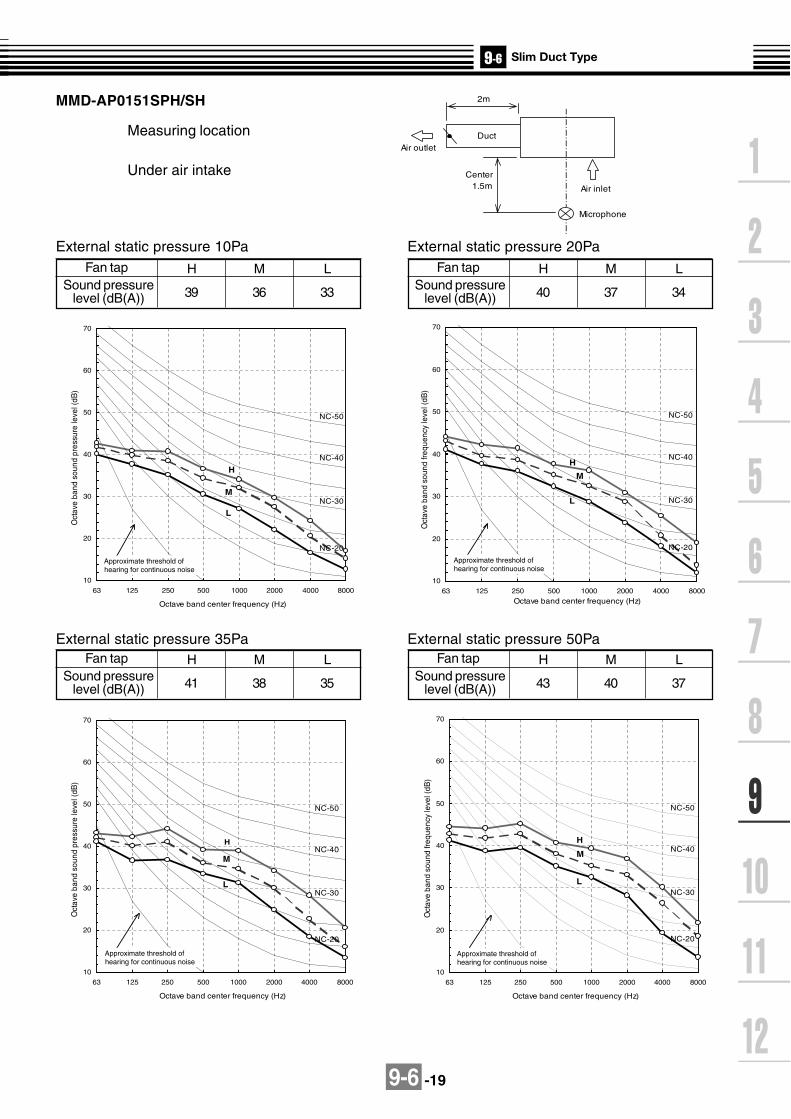
9-6 -19
10
20
30
40
50
60
70
63 125 250 500 1000 2000 4000 8000
Octave band center frequency (Hz)
Oct
ave
band
sou
nd fr
eque
ncy
leve
l (dB
)
L
H
M
NC-50
NC-40
NC-30
NC-20
hearing for continuous noiseApproximate threshold of
MMD-AP0151SPH/SH
Measuring location
Under air intake
Air outlet
Air inlet
2m
Center1.5m
Duct
Microphone
10
20
30
40
50
60
70
63 125 250 500 1000 2000 4000 8000
Octave band center frequency (Hz)
Oct
ave
band
sou
nd p
ress
ure
leve
l (dB
)
L
H
M
NC-50
NC-40
NC-30
NC-20
hearing for continuous noiseApproximate threshold of
10
20
30
40
50
60
70
63 125 250 500 1000 2000 4000 8000
L
H
M
NC-50
NC-40
NC-30
NC-20
hearing for continuous noiseApproximate threshold of
Octave band center frequency (Hz)
Oct
ave
band
sou
nd fr
eque
ncy
leve
l (dB
)
10
20
30
40
50
60
70
63 125 250 500 1000 2000 4000 8000
Octave band center frequency (Hz)
Oct
ave
band
sou
nd p
ress
ure
leve
l (dB
)
NC-50
NC-40
NC-30
NC-20
L
H
M
hearing for continuous noiseApproximate threshold of
External static pressure 10Pa External static pressure 20Pa
External static pressure 35Pa External static pressure 50Pa
Fan tapSound pressure
level (dB(A))
H M L
39 36 33
Fan tapSound pressure
level (dB(A))
H M L
40 37 34
Fan tapSound pressure
level (dB(A))
H M L
41 38 35
Fan tapSound pressure
level (dB(A))
H M L
43 40 37

9-6 -20
10
20
30
40
50
60
70
63 125 250 500 1000 2000 4000 8000
Octave band center frequency (Hz)
Oct
ave
band
sou
nd p
ress
ure
leve
l (dB
)
L
H
M
NC-50
NC-40
NC-30
NC-20
hearing for continuous noiseApproximate threshold of
MMD-AP0181SPH/SH
Measuring location
Under air intake
Air outlet
Air inlet
2m
Center1.5m
Duct
Microphone
10
20
30
40
50
60
70
63 125 250 500 1000 2000 4000 8000
Octave band center frequency (Hz)
Oct
ave
band
sou
nd p
ress
ure
leve
l (dB
)
L
H
M
NC-50
NC-40
NC-30
NC-20
hearing for continuous noiseApproximate threshold of
10
20
30
40
50
60
70
63 125 250 500 1000 2000 4000 8000
Octave band center frequency (Hz)
Oct
ave
band
sou
nd p
ress
ure
leve
l (dB
)
L
H
M
NC-50
NC-40
NC-30
NC-20
hearing for continuous noiseApproximate threshold of
10
20
30
40
50
60
70
63 125 250 500 1000 2000 4000 8000
Octave band center frequency (Hz)
Oct
ave
band
sou
nd p
ress
ure
leve
l (dB
)
NC-50
NC-40
NC-30
NC-20
L
H
M
hearing for continuous noiseApproximate threshold of
External static pressure 10Pa External static pressure 20Pa
External static pressure 35Pa External static pressure 50Pa
Fan tapSound pressure
level (dB(A))
H M L
40 38 36
Fan tapSound pressure
level (dB(A))
H M L
42 40 37
Fan tapSound pressure
level (dB(A))
H M L
43 41 38
Fan tapSound pressure
level (dB(A))
H M L
44 42 39

9-6 -21
9-6-7. Accessories
Apperarance
Standard accessories
Remote controller
Central remote controller TCB-SC642TLE2
ON-OFF controller TCB-CC163TLE2
Weekly timer application
Model Name
RBC-AMT31E
RBC-AS21E2
TCB-AX21E2
RBC-AMT31E and RBC-EXW21E2
Wired remote controller
Simple wired remote controller
Wireless remote controller kit
Optional accessories
Qty Shape Use
Installation Manual
Insulating pipe
Part name
Heat insulator
Flexible hose
Hose band
Washer
1
2
1
1
1
8 For hanging down unitM10 x Ø34
For connecting drain pipe
For centering the drain pipe
For sealing the wire connection opening
(Be sure to hand over to customer)
For insulating of pipe connecting section
—
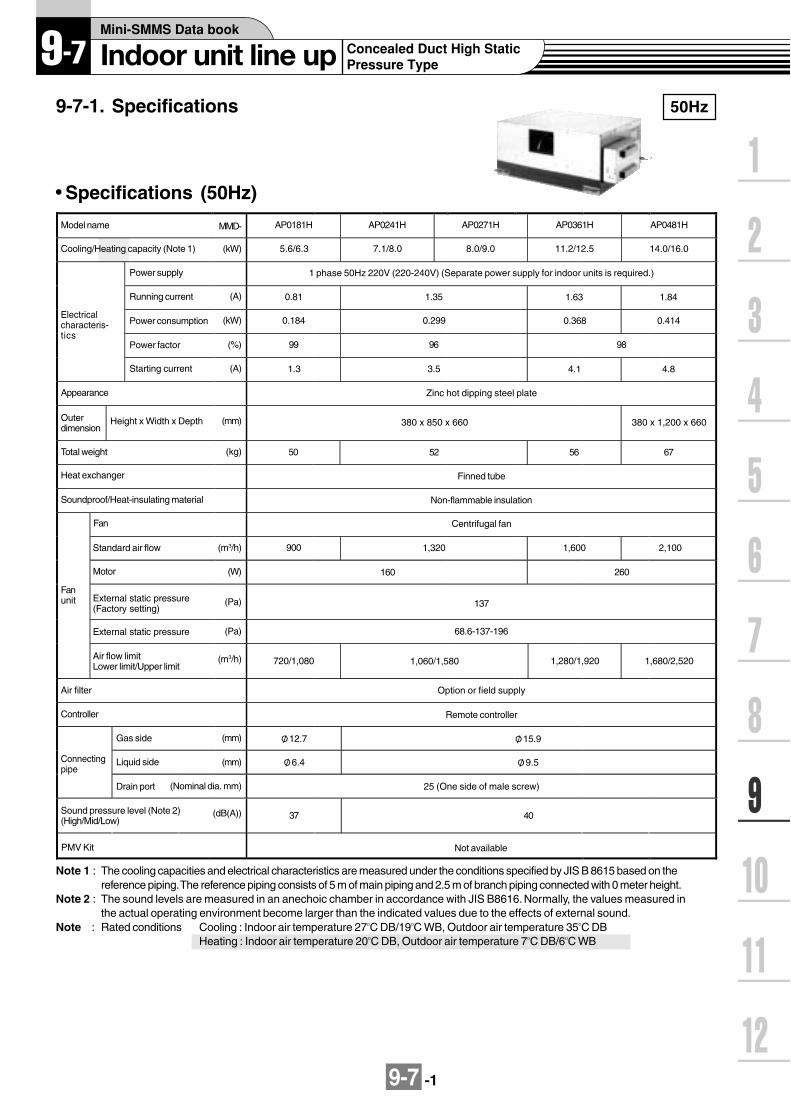
9-7 -1
9-7-1. Specifications 50Hz
Model name
Cooling/Heating capacity (Note 1)
AP0181H
5.6/6.3
Power supply
Electricalcharacteris-tics
Running current (A)
Power consumption
Power factor
Starting current
Appearance
Height x Width x DepthOuterdimension
Total weight
Heat exchanger
Soundproof/Heat-insulating material
Fan
Standard air flow
Motor
External static pressure
External static pressure(Factory setting)
Air flow limitLower limit/Upper limit
Fanunit
Air filter
Controller
Gas side
Liquid side
Drain port
Connectingpipe
MMD-
(kW)
(kW)
(%)
(A)
(mm)
(kg)
(m3/h)
(W)
(Pa)
(Pa)
(m3/h)
(mm)
(mm)
(Nominal dia. mm)
(dB(A))Sound pressure level (Note 2)(High/Mid/Low)
AP0241H
7.1/8.0
AP0271H
8.0/9.0
AP0361H
11.2/12.5
AP0481H
14.0/16.0
1 phase 50Hz 220V (220-240V) (Separate power supply for indoor units is required.)
0.81 1.35 1.63 1.84
0.184 0.299 0.368 0.414
99 96 98
1.3 3.5 4.1 4.8
Zinc hot dipping steel plate
380 x 850 x 660 380 x 1,200 x 660
50 6752 56
Finned tube
Non-flammable insulation
Centrifugal fan
900 2,1001,320 1,600
160 260
137
68.6-137-196
720/1,080 1,680/2,5201,060/1,580 1,280/1,920
Option or field supply
Remote controller
O/ 12.7 O/ 15.9
O/ 6.4 O/ 9.5
25 (One side of male screw)
37 40
Note 1 : The cooling capacities and electrical characteristics are measured under the conditions specified by JIS B 8615 based on thereference piping. The reference piping consists of 5 m of main piping and 2.5 m of branch piping connected with 0 meter height.
Note 2 : The sound levels are measured in an anechoic chamber in accordance with JIS B8616. Normally, the values measured inthe actual operating environment become larger than the indicated values due to the effects of external sound.
Note : Rated conditions Cooling : Indoor air temperature 27OC DB/19OC WB, Outdoor air temperature 35OC DBHeating : Indoor air temperature 20OC DB, Outdoor air temperature 7OC DB/6OC WB
PMV Kit Not available
Specifications (50Hz)

9-7 -2
60Hz
Model name
Cooling/Heating capacity (Note 1)
AP0181H
5.6/6.3
Power supply
Electricalcharacteris-tics
Running current (A)
Power consumption
Power factor
Starting current
Appearance
Height x Width x DepthOuterdimension
Total weight
Heat exchanger
Soundproof/Heat-insulating material
Fan
Standard air flow
Motor
External static pressure
External static pressure(Factory setting)
Air flow limitLower limit/Upper limit
Fanunit
Air filter
Controller
Gas side
Liquid side
Drain port
Connectingpipe
MMD-
(kW)
(kW)
(%)
(A)
(mm)
(kg)
(m3/h)
(W)
(Pa)
(Pa)
(m3/h)
(mm)
(mm)
(Nominal dia. mm)
(dB(A))Sound pressure level (Note 2)(High/Mid/Low)
AP0241H
7.1/8.0
AP0271H
8.0/9.0
AP0361H
11.2/12.5
AP0481H
14.0/16.0
1 phase 60Hz 220V (Separate power supply for indoor units is required.)
0.92 1.80 2.07 2.26
0.198 0.385 0.450 0.490
98 97 99
1.30 3.40 3.90 4.35
Zinc hot dipping steel plate
380 x 850 x 660 380 x 1,200 x 660
50 6752 56
Finned tube
Non-flammable insulation
Centrifugal fan
900 2,1001,320 1,600
160 260
137
68.6-137-196
720/1,080 1,680/2,5201,060/1,580 1,280/1,920
Option or field supply
Remote controller
O/ 12.7 O/ 15.9
O/ 6.4 O/ 9.5
25 (One side of male screw)
37 40
Note 1 : The cooling capacities and electrical characteristics are measured under the conditions specified by JIS B 8615 based on thereference piping. The reference piping consists of 5 m of main piping and 2.5 m of branch piping connected with 0 meter height.
Note 2 : The sound levels are measured in an anechoic chamber in accordance with JIS B8616. Normally, the values measured inthe actual operating environment become larger than the indicated values due to the effects of external sound.
Note : Rated conditions Cooling : Indoor air temperature 27OC DB/19OC WB, Outdoor air temperature 35OC DBHeating : Indoor air temperature 20OC DB, Outdoor air temperature 7OC DB/6OC WB
PMV Kit Not available
Specifications (60Hz)

9-7 -3
MMD-AP0181H, AP0241H, AP0271H, AP0361H, AP0481H
9-7-2. Dimension
AP0181H to AP0271H type
Model MMD- A B6.49.5
12.715.9
AP0361H type
Hole for hanging bolt(4-O/ 12 x 72)
Electric parts box
AP0181HAP0241H, AP0271H, AP0361H, AP0481H
Power supply/communicationpiping port (O/ 26)(Under electric parts box)
Refrigerant pipe connecting port(Gas side O/ B)
710
(Han
ging
bol
t mou
ntin
g pi
tch
800)
Power supply/communicationpiping port (O/ 26)(Under electric parts box)
Refrigerant pipe connecting port(Liquid side O/ A)
Screw hole for duct mounting (6-M6)
Air suction portDrain pipe connecting port (VP25)
Z view Z view
Z view
Air discharge portScrew hole for duct mounting (4-M6)
Screw hole for duct mounting (6-M6)
Hole for hanging bolt(4-O/ 12 x 72)
Electric parts box
Refrigerant pipe connecting port(Gas side O/ 15.9)
Refrigerant pipe connecting port(Liquid side O/ 9.5)
Screw hole for duct mounting (8-M6) Air suction port
Drain pipe connectingport (VP25)
Air discharge portScrew hole for duct mounting (8-M6)
16
4 2.7
120
120
Space required for installation and servicing *1
500
mm
or
mor
e60
0 m
mor
mor
e
Check port 600
Service space
Service space
Air discharge port
Note: All dimensions are in mm.
MMD-AP0181H to AP0361H MMD-AP0481H
Wireless remote controller kit TCB-AX21E2
Weekly timer application RBC-AMT31E and RBC-EXW21E2
Wired remote controller RBC-AMT31E
Simple wired remote controller RBC-AS21E2

9-7-4
9-7-3. Wirin
g d
iagram
Mo
del: M
MD
-AP
0181H, A
P0241H
, AP
0271H, A
P0361H
, AP
0481H
TC1TC2
CN080(GRN)
CN101(BLK)
CN073(RED)
CN070(WHI)
4 25 4 3 2 1
9 8 7 69 8 7 6
FANCN083(WHI)
DP(BLU)CN068
DP
CN304(GRY)
CN066(WHI)
CN067(BLK)
(BLK)PNL
EXCT
12
12
Filter
CN082(BLU)
CN060(WHI)
Option
CN032(WHI)
CN075(WHI)
CN074(WHI)
TR
T10
12
654321
654321
521346
521346
CN081(BLK)
12345
3
1 2 3 4 5 6
CN061(YEL)
Fan drive
1 2 3 4 5 61 2 3 4 5 61 2 3
1 2 31 3
1 21 21 2
1 2 31 2 3
1 2 31 2 3
4 5 6
CN050(WHI)
CN041(BLU)
CN040(BLU)
CN044(BRW)
1 21 2 3 4 5
RY004
P301
123
12
RY002RY006
RY007
RY005
1 2
BA
S(N)R(L)
U2
1 2Remote controller
CN1(WHI)
Power supplySingle phase
220-240V 50Hz 220V 60Hz
Indoor unitEarth screw
Outdoor unit
U1
U2U1
Powersupplycircuit
LM(GRN)CN033
1 2 31 2 3
CN100(BRN)
1 2 31 2 3
1 2 31 2 3
1 21 2
TCJ
CN102(RED)
1 21 2
TA
CN104(YEL)
FSCN030(RED)
1 21 2
RY001
TR
OCEMG
RC
FuseT5.0A
T10A,250V~
123
123
CN309(YEL)
123
123
REDWHI
H M L UL
PMV
(Option)
CN01(WHI)
CN02(BLU)
WHI
WHI
RED
GRY
WHI
RED
BLU
OR
N
BLK
BR
N
GRY
YEL
REDREDRED F
RED
WHI
43F1
6
4
CN03(RED)
MCC-1401
Network adaptor (Option)
1 21 2
1 21 2
X Y
3 32
1 1
43F1
Sparkkiller
8 7
43F1
5
3
1 2 3 41 2 3 4
F1 F2 F3 F4
RC
FM
WHI
BLK
BLU
ORNBRN
GRYRED 49F
Closedendconnector
Closed end connector
Wired for MMD-AP0481 only(BRN Wire)
Motor over heating protection switch
1 2 3 4 5 61 2 3 4 5 6
1 2 3 4 5 61 2 3 4 5 6
CN01(WHI)
CN02(YEL)
Sub P.C. boardMCC-1520Flow selector
unit earth screw
Indoor control P.C. board
Colorindication
RED : REDWHI : WHITEYEL : YELLOWBLU : BLUEBLK : BLACKGRY : GRAYPNK : PINKORN :ORANGEBRN : BROWNGRN : GREEN
Symbol
FM
RC
TR
TA
TC1,TC2,TCJ
RY005~007
RY001
RY002
PMV
F
43F1
D M
FS
Parts name
Fan motor
Running capacitor
Transformer
Indoor temp sensor
Temp sensor
Fan motor control relay
Flap motor control relay
Drain control relay
Pulse Motor Valve
Fuse
Fan motor control relay
Drain pump motor
Float switch
Soldseparately
1. indicates the terminal block, the letter inside indicates the terminal number.2. A dotted line and broken line indicate the wiring on site.3. indicates the control P.C. board.4. When installing a drain pump, Remove CN030 connector and connect float switch.5. A part is connected to the terminal block.
When a change is required due to the outside static pressure at site, check theterminal No. and lead colour of the fan motor in the below diagram and then changethe lead wire as indicated by the arrow mark ( ),
6. Pay attention when changing static pressure because the outside static pressureof H tap in 50 or 60Hz.
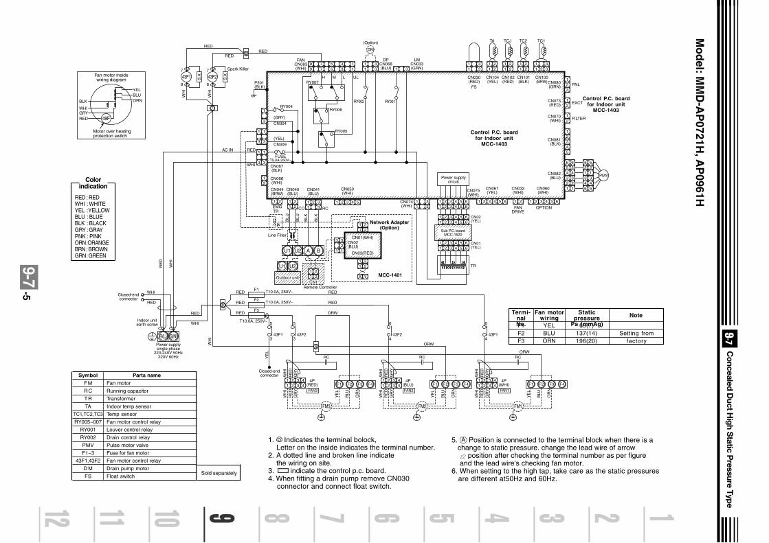
9-7-5
CN080(GRN) PNL
EXCT
23
1
2
2
3
3
4
4
5
56
1
12
2 2
3 3 34
4 4
55 56
6 61
1 1
CN073(RED) 2
1
FILTERCN070(WHI)
CN081(BLK)
CN082(BLU)
21
11
2 33
CN100(BRW)
11
22
CN101(BLK)
CN030(RED)
TC1TC2
11
22
CN102(RED)
TCJ
11
22
CN104(YEL)
TA
PMV
11
33
FS
5 3 177
99 5 3 1
RY007P301(BLK)
REDRED
Spark Killer
WH
I
WH
I
RED
YEL
BLK
WHIGRYRED
BLUORN
RY004
(GRY)CN304
(YEL)CN309
FUSET5.0A 250V~
RY006
RY005
H M L UL
3
1
3
1
3
1
3
1
3
1
6
8
7
21
11
221 2
11
22
11
2
X Y
2
32
1 1
3
11 2
33 1 2 3 4 5 1 2 3 4 5 6 1 2 1 23 4 5 6 1 2 3 4 5 6
1 2 3 4 5 6
CN066(WHI)
CN067(BLK)
AC IN RED
WHI
CN044(BRW)
EMG
Remote Controller
Power supplysingle phase
220-240V 50Hz220V 60Hz
Indoor unitearth screw
Closed-endconnector
Closed-endconnector
Line Filter
WHI
RED
RED
WHI
RE
D
WH
I
WH
I
CN01(WHI)
CN03(RED)
CN02(BLU)
CN040(BLU)
CN041(BLU)
CN050(WHI)
CN061(YEL)
CN032(WHI)
FANDRIVE
OPTION
CN060(WHI)
BLU
BLU
BLK
BLK
RCCOTR
U1 U2 A B
Network Adapter(Option)
MCC-140111
22
CN1
11
33CN074
(WHI)
CN075(WHI)
Power supplycircuit
TR
DPCN068(BLU)
LMCN033(GRN)
FANCN083(WHI)
RY002
1 3
RY001
R(L) S(N)
11
33
DM
(Option)
43F243F1
49F
F1 T10.0A, 250V~
T10.0A, 250V~
T10.0A, 250V~
RED
F2RED
F3RED
7
8
5
343F1
7
8
5
343F2
FAN3
4P(RED)
RC
ORW
RED
RED
ORW
ORW
YE
L
YE
L
WH
IR
ED
GR
Y
WH
IR
ED
GR
Y
BLU
OR
N
1 2 3 41 2 3 4
FM3
F1 F2 F3 F4
6
443F2
FAN2
4P(BLU)
RC
YE
L
WH
IR
ED
GR
Y
WH
IR
ED
GR
Y
BLU
OR
N
1 2 3 41 2 3 4
FM2
F1 F2 F3 F4
6
443F1
FAN1
4P(WHI)
RC
YE
L
WH
IR
ED
GR
Y
WH
IR
ED
GR
Y
BLU
OR
N
1 2 3 41 2 3 4
FM1
F1 F2 F3 F4
5
Motor over heatingprotection switch
Fan motor insidewiring diagram
U1 U2
Outdoor unit
1 2 3 4 5 61 2 3 4 5 6
1 2 3 4 5 61 2 3 4 5 6
CN01(YEL)
CN02(YEL)
Sub P.C. boardMCC-1520
S.K
S.K
Symbol
FM
RC
TR
TA
TC1,TC2,TC3
RY005~007
RY001
RY002
PMV
F1~3
43F1,43F2
D M
FS
Parts name
Fan motor
Running capacitor
Transformer
Indoor temp sensor
Temp sensor
Fan motor control relay
Louver control relay
Drain control relay
Pulse motor valve
Fuse for fan motor
Fan motor control relay
Drain pump motor
Float switchSold separately
Colorindication
RED : REDWHI : WHITEYEL : YELLOWBLU : BLUEBLK : BLACKGRY : GRAYPNK : PINKORN :ORANGEBRN : BROWNGRN : GREEN
Termi-nalNo.
Fan motorwiring
Staticpressure
Pa (mmAg)
Note
F1F2F3
YELBLUORN
69(7)137(14)196(20)
Setting fromfactory
Control P.C. boardfor Indoor unit
MCC-1403
Mo
del: M
MD
-AP
0721H, A
P0961H
Control P.C. boardfor Indoor unit
MCC-1403
1. Indicates the terminal bolock, Letter on the inside indicates the terminal number.2. A dotted line and broken line indicate the wiring on site.3. indicate the control p.c. board.4. When fitting a drain pump remove CN030 connector and connect float switch.
5. A Position is connected to the terminal block when there is a change to static pressure. change the lead wire of arrow position after checking the terminal number as per figure and the lead wire's checking fan motor.6. When setting to the high tap, take care as the static pressures are different at50Hz and 60Hz.
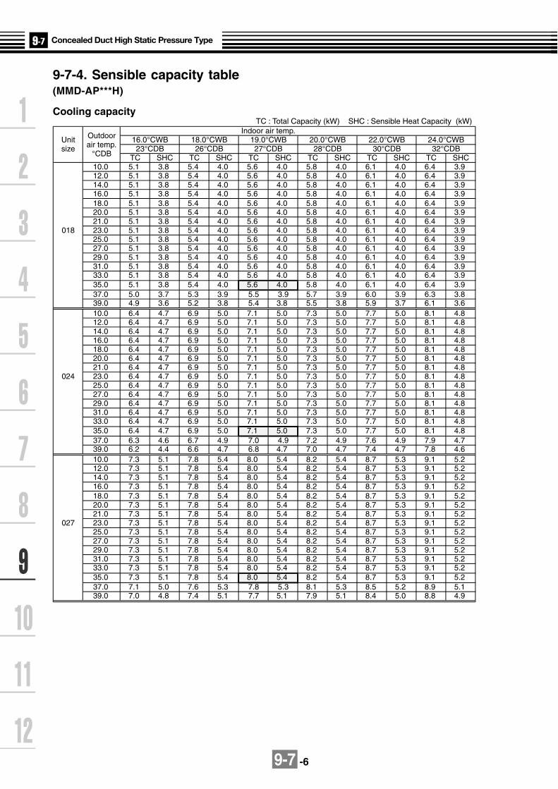
9-7 -6
TC : Total Capacity (kW) SHC : Sensible Heat Capacity (kW)Indoor air temp.
Unit Outdoor 16.0°CWB 18.0°CWB 19.0°CWB 20.0°CWB 22.0°CWB 24.0°CWBsize air temp. 23°CDB 26°CDB 27°CDB 28°CDB 30°CDB 32°CDB
°CDB TC SHC TC SHC TC SHC TC SHC TC SHC TC SHC10.0 5.1 3.8 5.4 4.0 5.6 4.0 5.8 4.0 6.1 4.0 6.4 3.912.0 5.1 3.8 5.4 4.0 5.6 4.0 5.8 4.0 6.1 4.0 6.4 3.914.0 5.1 3.8 5.4 4.0 5.6 4.0 5.8 4.0 6.1 4.0 6.4 3.916.0 5.1 3.8 5.4 4.0 5.6 4.0 5.8 4.0 6.1 4.0 6.4 3.918.0 5.1 3.8 5.4 4.0 5.6 4.0 5.8 4.0 6.1 4.0 6.4 3.920.0 5.1 3.8 5.4 4.0 5.6 4.0 5.8 4.0 6.1 4.0 6.4 3.921.0 5.1 3.8 5.4 4.0 5.6 4.0 5.8 4.0 6.1 4.0 6.4 3.9
018 23.0 5.1 3.8 5.4 4.0 5.6 4.0 5.8 4.0 6.1 4.0 6.4 3.925.0 5.1 3.8 5.4 4.0 5.6 4.0 5.8 4.0 6.1 4.0 6.4 3.927.0 5.1 3.8 5.4 4.0 5.6 4.0 5.8 4.0 6.1 4.0 6.4 3.929.0 5.1 3.8 5.4 4.0 5.6 4.0 5.8 4.0 6.1 4.0 6.4 3.931.0 5.1 3.8 5.4 4.0 5.6 4.0 5.8 4.0 6.1 4.0 6.4 3.933.0 5.1 3.8 5.4 4.0 5.6 4.0 5.8 4.0 6.1 4.0 6.4 3.935.0 5.1 3.8 5.4 4.0 5.6 4.0 5.8 4.0 6.1 4.0 6.4 3.937.0 5.0 3.7 5.3 3.9 5.5 3.9 5.7 3.9 6.0 3.9 6.3 3.839.0 4.9 3.6 5.2 3.8 5.4 3.8 5.5 3.8 5.9 3.7 6.1 3.610.0 6.4 4.7 6.9 5.0 7.1 5.0 7.3 5.0 7.7 5.0 8.1 4.812.0 6.4 4.7 6.9 5.0 7.1 5.0 7.3 5.0 7.7 5.0 8.1 4.814.0 6.4 4.7 6.9 5.0 7.1 5.0 7.3 5.0 7.7 5.0 8.1 4.816.0 6.4 4.7 6.9 5.0 7.1 5.0 7.3 5.0 7.7 5.0 8.1 4.818.0 6.4 4.7 6.9 5.0 7.1 5.0 7.3 5.0 7.7 5.0 8.1 4.820.0 6.4 4.7 6.9 5.0 7.1 5.0 7.3 5.0 7.7 5.0 8.1 4.821.0 6.4 4.7 6.9 5.0 7.1 5.0 7.3 5.0 7.7 5.0 8.1 4.8
024 23.0 6.4 4.7 6.9 5.0 7.1 5.0 7.3 5.0 7.7 5.0 8.1 4.825.0 6.4 4.7 6.9 5.0 7.1 5.0 7.3 5.0 7.7 5.0 8.1 4.827.0 6.4 4.7 6.9 5.0 7.1 5.0 7.3 5.0 7.7 5.0 8.1 4.829.0 6.4 4.7 6.9 5.0 7.1 5.0 7.3 5.0 7.7 5.0 8.1 4.831.0 6.4 4.7 6.9 5.0 7.1 5.0 7.3 5.0 7.7 5.0 8.1 4.833.0 6.4 4.7 6.9 5.0 7.1 5.0 7.3 5.0 7.7 5.0 8.1 4.835.0 6.4 4.7 6.9 5.0 7.1 5.0 7.3 5.0 7.7 5.0 8.1 4.837.0 6.3 4.6 6.7 4.9 7.0 4.9 7.2 4.9 7.6 4.9 7.9 4.739.0 6.2 4.4 6.6 4.7 6.8 4.7 7.0 4.7 7.4 4.7 7.8 4.610.0 7.3 5.1 7.8 5.4 8.0 5.4 8.2 5.4 8.7 5.3 9.1 5.212.0 7.3 5.1 7.8 5.4 8.0 5.4 8.2 5.4 8.7 5.3 9.1 5.214.0 7.3 5.1 7.8 5.4 8.0 5.4 8.2 5.4 8.7 5.3 9.1 5.216.0 7.3 5.1 7.8 5.4 8.0 5.4 8.2 5.4 8.7 5.3 9.1 5.218.0 7.3 5.1 7.8 5.4 8.0 5.4 8.2 5.4 8.7 5.3 9.1 5.220.0 7.3 5.1 7.8 5.4 8.0 5.4 8.2 5.4 8.7 5.3 9.1 5.221.0 7.3 5.1 7.8 5.4 8.0 5.4 8.2 5.4 8.7 5.3 9.1 5.2
027 23.0 7.3 5.1 7.8 5.4 8.0 5.4 8.2 5.4 8.7 5.3 9.1 5.225.0 7.3 5.1 7.8 5.4 8.0 5.4 8.2 5.4 8.7 5.3 9.1 5.227.0 7.3 5.1 7.8 5.4 8.0 5.4 8.2 5.4 8.7 5.3 9.1 5.229.0 7.3 5.1 7.8 5.4 8.0 5.4 8.2 5.4 8.7 5.3 9.1 5.231.0 7.3 5.1 7.8 5.4 8.0 5.4 8.2 5.4 8.7 5.3 9.1 5.233.0 7.3 5.1 7.8 5.4 8.0 5.4 8.2 5.4 8.7 5.3 9.1 5.235.0 7.3 5.1 7.8 5.4 8.0 5.4 8.2 5.4 8.7 5.3 9.1 5.237.0 7.1 5.0 7.6 5.3 7.8 5.3 8.1 5.3 8.5 5.2 8.9 5.139.0 7.0 4.8 7.4 5.1 7.7 5.1 7.9 5.1 8.4 5.0 8.8 4.9
9-7-4. Sensible capacity table(MMD-AP***H)
Cooling capacity
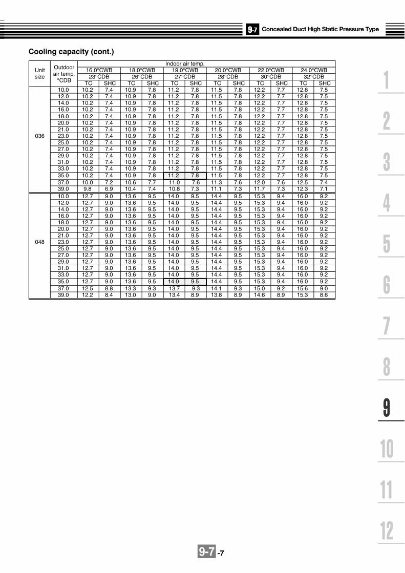
9-7 -7
Cooling capacity (cont.)
Indoor air temp.Unit Outdoor 16.0°CWB 18.0°CWB 19.0°CWB 20.0°CWB 22.0°CWB 24.0°CWBsize air temp. 23°CDB 26°CDB 27°CDB 28°CDB 30°CDB 32°CDB
°CDB TC SHC TC SHC TC SHC TC SHC TC SHC TC SHC10.0 10.2 7.4 10.9 7.8 11.2 7.8 11.5 7.8 12.2 7.7 12.8 7.512.0 10.2 7.4 10.9 7.8 11.2 7.8 11.5 7.8 12.2 7.7 12.8 7.514.0 10.2 7.4 10.9 7.8 11.2 7.8 11.5 7.8 12.2 7.7 12.8 7.516.0 10.2 7.4 10.9 7.8 11.2 7.8 11.5 7.8 12.2 7.7 12.8 7.518.0 10.2 7.4 10.9 7.8 11.2 7.8 11.5 7.8 12.2 7.7 12.8 7.520.0 10.2 7.4 10.9 7.8 11.2 7.8 11.5 7.8 12.2 7.7 12.8 7.521.0 10.2 7.4 10.9 7.8 11.2 7.8 11.5 7.8 12.2 7.7 12.8 7.5
036 23.0 10.2 7.4 10.9 7.8 11.2 7.8 11.5 7.8 12.2 7.7 12.8 7.525.0 10.2 7.4 10.9 7.8 11.2 7.8 11.5 7.8 12.2 7.7 12.8 7.527.0 10.2 7.4 10.9 7.8 11.2 7.8 11.5 7.8 12.2 7.7 12.8 7.529.0 10.2 7.4 10.9 7.8 11.2 7.8 11.5 7.8 12.2 7.7 12.8 7.531.0 10.2 7.4 10.9 7.8 11.2 7.8 11.5 7.8 12.2 7.7 12.8 7.533.0 10.2 7.4 10.9 7.8 11.2 7.8 11.5 7.8 12.2 7.7 12.8 7.535.0 10.2 7.4 10.9 7.8 11.2 7.8 11.5 7.8 12.2 7.7 12.8 7.537.0 10.0 7.2 10.6 7.7 11.0 7.6 11.3 7.6 12.0 7.6 12.5 7.439.0 9.8 6.9 10.4 7.4 10.8 7.3 11.1 7.3 11.7 7.3 12.3 7.110.0 12.7 9.0 13.6 9.5 14.0 9.5 14.4 9.5 15.3 9.4 16.0 9.212.0 12.7 9.0 13.6 9.5 14.0 9.5 14.4 9.5 15.3 9.4 16.0 9.214.0 12.7 9.0 13.6 9.5 14.0 9.5 14.4 9.5 15.3 9.4 16.0 9.216.0 12.7 9.0 13.6 9.5 14.0 9.5 14.4 9.5 15.3 9.4 16.0 9.218.0 12.7 9.0 13.6 9.5 14.0 9.5 14.4 9.5 15.3 9.4 16.0 9.220.0 12.7 9.0 13.6 9.5 14.0 9.5 14.4 9.5 15.3 9.4 16.0 9.221.0 12.7 9.0 13.6 9.5 14.0 9.5 14.4 9.5 15.3 9.4 16.0 9.2
048 23.0 12.7 9.0 13.6 9.5 14.0 9.5 14.4 9.5 15.3 9.4 16.0 9.225.0 12.7 9.0 13.6 9.5 14.0 9.5 14.4 9.5 15.3 9.4 16.0 9.227.0 12.7 9.0 13.6 9.5 14.0 9.5 14.4 9.5 15.3 9.4 16.0 9.229.0 12.7 9.0 13.6 9.5 14.0 9.5 14.4 9.5 15.3 9.4 16.0 9.231.0 12.7 9.0 13.6 9.5 14.0 9.5 14.4 9.5 15.3 9.4 16.0 9.233.0 12.7 9.0 13.6 9.5 14.0 9.5 14.4 9.5 15.3 9.4 16.0 9.235.0 12.7 9.0 13.6 9.5 14.0 9.5 14.4 9.5 15.3 9.4 16.0 9.237.0 12.5 8.8 13.3 9.3 13.7 9.3 14.1 9.3 15.0 9.2 15.6 9.039.0 12.2 8.4 13.0 9.0 13.4 8.9 13.8 8.9 14.6 8.9 15.3 8.6

9-7 -8
SHC : Sensible Heat Capacity (kW)
Unit Outdoor Indoor air temp. °CDB
size air temp. 16.0 18.0 20.0 22.0 24.0°CWB SHC SHC SHC SHC SHC-15.0 3.9 3.9 3.8 3.7 3.6-13.0 4.2 4.1 4.0 3.9 3.8-11.0 4.5 4.4 4.3 4.2 4.1-10.0 4.6 4.5 4.4 4.3 4.2-8.0 4.9 4.8 4.7 4.6 4.4-6.0 5.1 5.0 4.9 4.8 4.7-4.0 5.4 5.3 5.2 5.0 4.9
018 -2.0 5.6 5.5 5.4 5.3 5.10.0 5.9 5.8 5.6 5.5 5.32.0 6.1 6.0 5.9 5.7 5.64.0 6.3 6.2 6.1 5.9 5.86.0 6.6 6.4 6.3 6.1 6.08.0 6.6 6.4 6.3 6.1 6.0
10.0 6.6 6.4 6.3 6.1 6.012.0 6.6 6.4 6.3 6.1 6.014.0 6.6 6.4 6.3 6.1 6.0-15.0 5.0 4.9 4.8 4.7 4.6-13.0 5.3 5.2 5.1 5.0 4.9-11.0 5.7 5.6 5.5 5.3 5.2-10.0 5.8 5.7 5.6 5.5 5.3-8.0 6.2 6.1 5.9 5.8 5.6-6.0 6.5 6.4 6.2 6.1 5.9-4.0 6.8 6.7 6.6 6.4 6.2
024 -2.0 7.1 7.0 6.9 6.7 6.50.0 7.4 7.3 7.1 7.0 6.82.0 7.7 7.6 7.4 7.3 7.14.0 8.0 7.9 7.7 7.5 7.36.0 8.3 8.2 8.0 7.8 7.68.0 8.3 8.2 8.0 7.8 7.6
10.0 8.3 8.2 8.0 7.8 7.612.0 8.3 8.2 8.0 7.8 7.614.0 8.3 8.2 8.0 7.8 7.6-15.0 5.6 5.5 5.4 5.3 5.1-13.0 6.0 5.9 5.8 5.6 5.5-11.0 6.4 6.3 6.1 6.0 5.8-10.0 6.6 6.5 6.3 6.2 6.0-8.0 7.0 6.8 6.7 6.5 6.3-6.0 7.3 7.2 7.0 6.9 6.7-4.0 7.7 7.5 7.4 7.2 7.0
027 -2.0 8.0 7.9 7.7 7.5 7.30.0 8.4 8.2 8.0 7.8 7.62.0 8.7 8.5 8.4 8.2 7.94.0 9.0 8.9 8.7 8.5 8.36.0 9.4 9.2 9.0 8.8 8.68.0 9.4 9.2 9.0 8.8 8.6
10.0 9.4 9.2 9.0 8.8 8.612.0 9.4 9.2 9.0 8.8 8.614.0 9.4 9.2 9.0 8.8 8.6
Heating capacity

9-7 -9
Unit Outdoor Indoor air temp. °CDB
size air temp. 16.0 18.0 20.0 22.0 24.0
°CWB SHC SHC SHC SHC SHC-15.0 7.8 7.7 7.5 7.3 7.2-13.0 8.3 8.2 8.0 7.8 7.6-11.0 8.9 8.7 8.5 8.3 8.1-10.0 9.1 9.0 8.8 8.6 8.3-8.0 9.7 9.5 9.3 9.1 8.8-6.0 10.2 10.0 9.8 9.5 9.3-4.0 10.7 10.5 10.2 10.0 9.7
036 -2.0 11.1 10.9 10.7 10.5 10.20.0 11.6 11.4 11.2 10.9 10.62.0 12.1 11.9 11.6 11.3 11.04.0 12.6 12.3 12.1 11.8 11.56.0 13.0 12.8 12.5 12.2 11.98.0 13.0 12.8 12.5 12.2 11.9
10.0 13.0 12.8 12.5 12.2 11.912.0 13.0 12.8 12.5 12.2 11.914.0 13.0 12.8 12.5 12.2 11.9-15.0 10.0 9.8 9.6 9.4 9.1-13.0 10.7 10.5 10.3 10.0 9.7-11.0 11.4 11.1 10.9 10.7 10.4-10.0 11.7 11.5 11.2 11.0 10.7-8.0 12.4 12.1 11.9 11.6 11.3-6.0 13.0 12.8 12.5 12.2 11.9-4.0 13.6 13.4 13.1 12.8 12.4
048 -2.0 14.3 14.0 13.7 13.4 13.00.0 14.9 14.6 14.3 14.0 13.62.0 15.5 15.2 14.9 14.5 14.14.0 16.1 15.8 15.4 15.1 14.76.0 16.7 16.3 16.0 15.6 15.28.0 16.7 16.3 16.0 15.6 15.2
10.0 16.7 16.3 16.0 15.6 15.212.0 16.7 16.3 16.0 15.6 15.214.0 16.7 16.3 16.0 15.6 15.2
Heating capacity (cont.)

9-7 -10
9-7-5. Fan characteristics
MMD-AP0181H
MMD-AP0361H
MMD-AP0241H, AP0271H
MMD-AP0481H
Fan
mot
or c
urre
nt (
A)
Out
side
sta
tic p
ress
ure
(Pa)
1.5
1.0
0.5
250
200
150
100
50
700 800 900 1,000 1,1000
Air volume (m³/h)
High static pressure tap
High static pressure tap
Medium static pressure tap
Low static pressure tap
Medium static pressure tap
Low static pressure tap
Air
volu
me
low
er li
mit
Air
volu
me
uppe
r lim
it50Hz60Hz
Standard air volume: 900 m3/h
Fan
mot
or c
urre
nt (
A)
Out
side
sta
tic p
ress
ure
(Pa)
2.0
1.5
1.0
300
250
200
150
50
100
1,000 1,100 1,200 1,3001,320
1,400 1,500 1,6000
Air volume (m³/h)
High static pressure tap
High static pressure tapMedium static pressure tap
Low static pressure tap
Medium static pressure tap
Low static pressure tap
Air
volu
me
low
er li
mit
Air
volu
me
uppe
r lim
it
50Hz60Hz
Standard air volume: 1,320 m3/h
Fan
mot
or c
urre
nt (
A)
Out
side
sta
tic p
ress
ure
(Pa)
2.5
2.0
1.5
1.0
250
200
150
100
50
1,400 1,500 1,600 1,700 1,8000
Air volume (m³/h)
High static pressure tap
Low static pressure tap
Medium static pressure tap
Low static pressure tap
Air
volu
me
low
er li
mit
Air
volu
me
uppe
r lim
it
Standard air volume: 1,600 m3/h
50Hz60Hz
High static pressure tap
Medium static pressure tap
Fan
mot
or c
urre
nt (
A)
Out
side
sta
tic p
ress
ure
(Pa)
2.0
2.5
3.0
1.5
0.5
250
200
150
50
100
1,500 2,000
2,100
2,5000
Air volume (m³/h)
High static pressure tap
High static pressure tap
Low static pressure tap
Medium static pressure tapLow static pressure tap
Air
volu
me
low
er li
mit
Air
volu
me
uppe
r lim
it50Hz60Hz
Standard air volume: 2,100 m3/h
Medium static pressure tap

9-7 -11
9-7-6. Sound characteristics (NC-Curve)
Sound level values shown are based on a measurement in a non resound room.
Microphone
MMD-AP0181H
Oct
ave
band
sou
nd p
ress
ure
leve
l (dB
)
Octave band center frequency (Hz)
Audibility limitsof continuouswhite level
196.0(external static pressure(Pa))
(standard sound pressure 0.0002 µbar) (standard sound pressure 0.0002 µbar)
(standard sound pressure 0.0002 µbar) (standard sound pressure 0.0002 µbar)
MMD-AP0241H, AP0271H
Audibility limitsof continuouswhite level
Octave band center frequency (Hz)
Oct
ave
band
sou
nd p
ress
ure
leve
l (dB
)
Oct
ave
band
sou
nd p
ress
ure
leve
l (dB
)
Oct
ave
band
sou
nd p
ress
ure
leve
l (dB
)
196.0(external static pressure(Pa))
Outside still pressure
Overall level(dB)
68.6 (Pa)
33
46
A
C
137.2 (Pa)
37
51
196.0 (Pa)
40
53
(dB)
Outside still pressure
Overall level(dB)
68.6 (Pa)
33
47
A
C
137.2 (Pa)
37
49
196.0 (Pa)
40
53
(dB)
Outside still pressure
Overall level(dB)
68.6 (Pa)
36
50.5
A
C
137.2 (Pa)
40
53
196.0 (Pa)
44
57
(dB)
Outside still pressure
Overall level(dB)
68.6 (Pa)
36
50
A
C
137.2 (Pa)
40
53
196.0 (Pa)
44
57
(dB)
Audibility limitsof continuouswhite level
Audibility limitsof continuouswhite level
Octave band center frequency (Hz) Octave band center frequency (Hz)
196.0(external static pressure(Pa)) 196.0(external static pressure(Pa))

9-7 -12
MMD-AP0361HO
ctav
e ba
nd s
ound
pre
ssur
e le
vel (
dB)
Octave band center frequency (Hz)
Audibility limitsof continuouswhite level
196.0(external static pressure(Pa))
(dB)
(standard sound pressure 0.0002 µbar) (standard sound pressure 0.0002 µbar)
Oct
ave
band
sou
nd p
ress
ure
leve
l (dB
)
Octave band center frequency (Hz)
Audibility limitsof continuouswhite level
196.0(external static pressure(Pa))
(standard sound pressure 0.0002 µbar)
Oct
ave
band
sou
nd p
ress
ure
leve
l (dB
)
Octave band center frequency (Hz)
Audibility limitsof continuouswhite level
196.0(external static pressure(Pa))
(standard sound pressure 0.0002 µbar)
Oct
ave
band
sou
nd p
ress
ure
leve
l (dB
)
Octave band center frequency (Hz)
Audibility limitsof continuouswhite level
196.0(external static pressure(Pa))
Outside still pressure
Overall level(dB)
68.6 (Pa)
36
49.5
A
C
137.2 (Pa)
40
54
196.0 (Pa)
44
59
Outside still pressure
Overall level(dB)
68.6 (Pa)
36
49
A
C
137.2 (Pa)
40
53.5
196.0 (Pa)
44
57
(dB)
Outside still pressure
Overall level(dB)
68.6 (Pa)
36
47
A
C
137.2 (Pa)
40
51
196.0 (Pa)
44
54
(dB)
Outside still pressure
Overall level(dB)
68.6 (Pa)
36
47
A
C
137.2 (Pa)
40
51
196.0 (Pa)
44
54
(dB)

9-7 -13
Sound level data (NC CURVE) Sound level values shown are based on a measurement in a non resound room.
MMD-AP0721H
Oct
ave
band
sou
nd p
ress
ure
leve
l (dB
)
Octave band center frequency (Hz)
Audibility limitsof continuouswhite level
Outside still pressure
Overall level(dB)
69 (Pa)
48
54
A
(50Hz)
C
137 (Pa)
49
55
196 (Pa)
50.5
57
Outside still pressure
Overall level(dB)
69 (Pa)
48
55
A
(60Hz)
C
137 (Pa)
49
50
196 (Pa)
50.5
58
Outside still pressure
Overall level(dB)
69 (Pa)
49
56
A
(50Hz)
C
137 (Pa)
50
59
196 (Pa)
51.5
61
Outside still pressure
Overall level(dB)
69 (Pa)
49
57
A
(60Hz)
C
137 (Pa)
50
59
196 (Pa)
51.5
61
MMD-AP0961H
Oct
ave
band
sou
nd p
ress
ure
leve
l (dB
)
Oct
ave
band
sou
nd p
ress
ure
leve
l (dB
)
Oct
ave
band
sou
nd p
ress
ure
leve
l (dB
)
Octave band center frequency (Hz)
Octave band center frequency (Hz) Octave band center frequency (Hz)
Audibility limitsof continuouswhite level
Audibility limitsof continuouswhite level
Audibility limitsof continuouswhite level

9-7 -14
9-7-7. Accessories
Apperarance
Standard accessories
Remote controller
TCB-AX21E2 Wireless remote controller kit
Central remote controller
ON-OFF controller
TCB-SC642TLE2
TCB-CC163TLE2
Weekly timer application RBC-AMT31E and RBC-EXW21E2
Wired remote controller
Simple wired remote controller
Model Name
RBC-AMT31E
RBC-AS21E2
Part name Qty Shape Use Part name Qty Shape Use
Installation Manual 1 Insulation 1 For insulating the liquid pipe
connection
Insulation 1 For insulating the gas pipe connection

9-7 -15
High Efficiency Filter 65 TCB-UFM1D-1E, TCB-UFM2D-1E
High Efficiency Filter 90 TCB-UFH5D-1E, TCB-UFH6D-1E
Long Life Pre-Filter
TCB-PF1D-1ETCB-PF2D-1E
Filter Chamber
TCB-FCY21DE, TCB-FCY31DETCB-FCY51DE
Drain pump kit
TCB-DP31DE
Optional accessories
Name Model name Note
TCB-UFM1D-1E
TCB-UFM2D-1E(2 pcs.)
TCB-UFM1D-1E(2 pcs.)
TCB-UFH5D-1E
TCB-UFH6D-1E (2 pcs.)
TCB-UFH5D-1E (2 pcs.)
TCB-PF1D-1E
TCB-PF2D-1E (2 pcs.)
TCB-PF1D-1E (2 pcs.)
TCB-FCY21DE
TCB-FCY31DE
TCB-FCY51DE
TCB-DP31DE
High Efficiency Filter 65
High Efficiency Filter 90
Long life Pre-filter
Filter Chamber
Drain Pump Kit
Dust collecting effect :65%(NBS Colorimentric method)Use with TCB-FCY21D
Dust collecting effect :65%(NBS Colorimentric method)Use with TCB-FCY31D
Dust collecting effect :65%(NBS Colorimentric method)Use with TCB-FCY41D
Dust collecting effect :90%(NBS Colorimentric method)Use with TCB-FCY21D
Dust collecting effect :90%(NBS Colorimentric method)Use with TCB-FCY31D
Dust collecting effect :90%(NBS Colorimentric method)Use with TCB-FCY41D
Dust collecting effect :50%(Weight method)Use with TCB-FCY21D
Dust collecting effect :50%(Weight method)Use with TCB-FCY31D
Dust collecting effect :50%(Weight method)Use with TCB-FCY41D
For high efficiency filter or long life pre-filter
Stand-up 330 or less(from bottom face of ceiling)

9-8 -1
9-8-1. Specifications 50Hz
Specifications (50Hz)
Note 1 : The cooling capacities and electrical characteristics are measured under the conditions specified by JIS B 8615 based on thereference piping. The reference piping consists of 5 m of main piping and 2.5 m of branch piping connected with 0 meter height.
Note 2 : The sound level are measured in an anechoic chamber in accordance with JIS B8616. Normally, the values measured in theactual operating environment become larger than the indicated values due to the effects of external sound.
Note : Rated conditions Cooling : Indoor air temperature 27oC DB/19oC WB, Outdoor air temperature 35oC DBHeating : Indoor air temperature 20oC DB, Outdoor air temperature 7oC DB/6oC WB
Cooling/Heating capacity (Note 1) (kW)
Electricalcharacteristics
Power supply
Running current (A)
Power consumption
(kW)
Starting current (A)
Model name MMC-
Appearance
Outerdimension Height x Width x Depth (mm)
Total weight (kg)
Heat exchanger
Soundproof/Heat-insulating material
Fan unit
Fan
Standard air flow(High/Mid/Low)
(m3/h)
Motor (W)
Controller
Air filter
AP0151H
4.5/5.0
1 phase 50Hz 230V (220-240V) (Separate power supply for indoor units is required.)
0.29
0.033
0.43
AP0181H
5.6/6.3
AP0241H
7.1/8.0
AP0271H
8.0/9.0
AP0361H
11.2/12.5
AP0481H
14.0/16.0
0.42
0.050
0.62
0.78
0.091
1.17
0.84
0.110
1.25
0.32
0.038
0.48
White (Munsell 10Y 9.3/0.4)
210 x 910 x 680 210 x 1,180 x 680 210 x 1,595 x 680
22 26 34
Finned tube
Non-flammable insulation
Centrifugal fan
720/600/540 1,110/900/840 1,650/1,380/1,200
780/660/540 1,800/1,560/1,320
30 40 80
Remote controller
Standard filter (Long life filter)
Gas side (mm)
Liquid side (mm)Connectingpipe
Sound pressure level (Note 2)(High/Mid/Low) (dB(A))
O/ 12.7
O/ 6.4
O/ 15.9
O/ 9.5
20 (Polyvinyl chloride tube)
35/32/30 38/36/33 41/38/3536/33/30 43/40/37
PMV Kit Not available
Drain port (Nominal dia. mm)

9-8 -2
60Hz
Model name MMC-
(kW)
AP0151H
4.5/5.0
Power supply
Electricalcharacteristics
Running current (A)
Power consumption
Starting current
Appearance
Height x Width x DepthOuterdimension
Total weight
Heat exchanger
Soundproof/Heat-insulating material
Standard air flow(High/Mid/Low)
Fan
Motor
Fan unit
Controller
(kW)
(A)
(mm)
(kg)
(m3/h)
(W)
AP0181H
5.6/6.3
AP0241H
7.1/8.0
AP0271H
8.0/9.0
AP0361H
11.2/12.5
AP0481H
14.0/16.0
1 phase 60Hz 220V (Separate power supply for indoor units is required.)
0.30 0.34 0.44 0.82 0.87
0.033 0.038 0.050 0.091 0.110
0.43 0.48 0.62 1.17 1.25
White (Munsell 10Y 9.3/0.4)
210 x 910 x 680 210 x 1,180 x 680 210 x 1,595 x 680
22 26 34
Finned tube
Non-flammable insulation
Centrifugal fan
720/600/540 1,110/900/840 1,650/1,380/1,200 1,800/1,560/1,320780/660/540
30 40 80
Remote controller
Note 1 : The cooling capacities and electrical characteristics are measured under the conditions specified by JIS B 8615 based on thereference piping. The reference piping consists of 5 m of main piping and 2.5 m of branch piping connected with 0 meter height.
Note 2 : The sound levels are measured in an anechoic chamber in accordance with JIS B8616. Normally, the values measured inthe actual operating environment become larger than the indicated values due to the effects of external sound.
Note : Rated conditions Cooling : Indoor air temperature 27OC DB/19OC WB, Outdoor air temperature 35OC DBHeating : Indoor air temperature 20OC DB, Outdoor air temperature 7OC DB/6OC WB
Cooling/Heating capacity (Note 1)
Specifications (60Hz)
Air filter
Gas side
Liquid side
Drain port
Connectingpipe
Sound pressure level (Note 2)(High/Mid/Low)
(mm)
(mm)
(Nominal dia. mm)
(db(A))
Standard filter (Long life filter)
O/ 12.7 O/ 15.9
O/ 6.4 O/ 9.5
20 (Polyvinyl chloride tube)
35/32/30 38/36/33 41/38/35 43/40/3736/33/30
PMV Kit Not available

9-8 -3
MMC-AP0151H, AP0181H, AP0241H, AP0271H, AP0361H, AP0481H
9-8-2. Dimension
Remote controller piping taking-in port (Knockout hole)
Upper piping drawing-out port (Knockout hole)
Power supply cable taking-in port (Knockout)
Left drain size
B (Hanging position)
500
or m
ore
Refrigerant pipe (Liquid side O/O/
D)
Refrigerant pipe (Gas side C)
Drain pipe connecting port
Piping drawing-out port (Knockout port)
Drain port VP20 (Inner diam. O/ 26, hose supplied)
Wireless sensor mounting section(Optional)
250 or more250 or more
(Han
ging
pos
ition
)
320
170
70
16
4 2.7
120
120
Piping hole on the wall (O/ 100 hole)
Drain left piping drawing-out port (Knockout hole)
Air taking-in port (Duct sold separately) (Knockout hole O/ 92)
Remote controller cable taking-in port
Power supply taking-in port (Knockout hole)
Remote controller cable taking-in port (Knockout hole)
(Front side to be positioned horizontally.)
Hanging bolt
Ceiling surface
With
in 5
0
Unit
A
Space required for installation and servicing
Model MMC-
AP0151H, AP0181H
AP0241H, AP0271H
AP0361H, AP0481H
A
910
1180
1595
B
855
1125
1540
C
12.7
15.9
15.9
D
6.4
9.5
9.5
Note: All dimensions are in mm.
Wired remote controller RBC-AMT31E
Simple wired remote controller RBC-AS21E2
Wireless remote controller kit TCB-AX22CE2
Weekly timer application RBC-AMT31E and RBC-EXW21E2

9-8-4
9-8-3. Wirin
g d
iagram
Mo
del: M
MC
-AP
0151H, A
P0181H
, AP
0241H, A
P0271H
, AP
0361H, A
P0481H
CN104(YEL)
CN102(RED)
CN101(BLK)
1 2 3 4 51 2 3 4 5
1 2 3 4 51
11
2
22
3
33
4
44
5
55
66
66
1 2 3 4 51 2 3 4 5
1 31 2 3
CN34(RED)
FS
CN33(WHI)
CN82(BLU)
5 4 15 4 3 2 1
CN334(WHI)
DC20V
CN333(WHI)CN68
(BLU)
CN304(GRY)
CN66(WHI)
CN67(BLK)
12
12
TA12
12
TCJ12
12
TC2
CN80(GRN)
PNL
EXCT
12
CN73(RED)
12
FILTER
Option GRLFandrive
CN70(WHI)
CN20(BLU)
12
3
1 2 3 4 51 2 3 4 5
LM
1 2 3 4 5
CN60(WHI)
CN32(WHI)
CN61(YEL)
CN50(WHI)
Adpter for wirelessremote controller
CN309(YEL)
CN41(BLU)
T10
1 21 2 3 4 5 6
CN81(BLK)
1 2 3 4 51 2 3 4 51 2 31 2 31 2 3
CN40(BLU)
4 5 6
1 21 2
RY302123
123
123
123
12
12
12
12
1
33
12
3
RY303
~ +
~ Ð
FuseT6.3A250V~
FuseT3.15A
DC15VDC12VDC7V
P301BLK
REDWHI
Closed endterminal
RE
D
WH
I
Wired remote controller
Outdoor unit 1 2
BAU2U1
U2U1
1 2
CN1(WHI)
CN001(WHI)
Indoor unit
Earth screw
WHI BLK BLKWHI
BLK
TR
BLU
WHI
BLU
BLK
BLK
DM
FM
Powersupplycircuit
Motor drive circuit
CN01(WHI)
CN02(BLU) CN03
(RED)
Network adaptor(Option)
1 21 2
1 21 2
X Y
3 32 21 1
Network adaptorP.C. board
S(N)R(L)
Power supplysingle phase
200-240V 50Hz 200V 60Hz
PMV
Flow selector unit earth
screw
CN100(BRW)
12
12
33 TC1
Color identificationRED : REDWHI : WHITEYEL : YELLOWBLU : BLUEBRN : BROWN
BLK : BLACKGRY : GRAYPNK : PINKORN : ORANGEGRN : GREEN
Symbol
FM
TA
TC1,TC2,TCJ
LM
RY302
D M
FSSoldseparately
Parts name
Fan motor
Indoor temp sensor
Temp sensor
Louver motor
Drain control relay
Drain pump motor
Float switch
Indoor control P.C. board
1. indicates the terminal block, the letter inside
indicates the terminal number.
2. A dotted line and broken line indicate the wiring on site.
3. indicates the control P.C. board.

9-8 -5
TC : Total Capacity (kW) SHC : Sensible Heat Capacity (kW)Indoor air temp.
Unit Outdoor 16.0°CWB 18.0°CWB 19.0°CWB 20.0°CWB 22.0°CWB 24.0°CWBsize air temp. 23°CDB 26°CDB 27°CDB 28°CDB 30°CDB 32°CDB
°CDB TC SHC TC SHC TC SHC TC SHC TC SHC TC SHC10.0 4.1 3.0 4.4 3.2 4.5 3.2 4.6 3.2 4.9 3.2 5.1 3.112.0 4.1 3.0 4.4 3.2 4.5 3.2 4.6 3.2 4.9 3.2 5.1 3.114.0 4.1 3.0 4.4 3.2 4.5 3.2 4.6 3.2 4.9 3.2 5.1 3.116.0 4.1 3.0 4.4 3.2 4.5 3.2 4.6 3.2 4.9 3.2 5.1 3.118.0 4.1 3.0 4.4 3.2 4.5 3.2 4.6 3.2 4.9 3.2 5.1 3.120.0 4.1 3.0 4.4 3.2 4.5 3.2 4.6 3.2 4.9 3.2 5.1 3.121.0 4.1 3.0 4.4 3.2 4.5 3.2 4.6 3.2 4.9 3.2 5.1 3.1
015 23.0 4.1 3.0 4.4 3.2 4.5 3.2 4.6 3.2 4.9 3.2 5.1 3.125.0 4.1 3.0 4.4 3.2 4.5 3.2 4.6 3.2 4.9 3.2 5.1 3.127.0 4.1 3.0 4.4 3.2 4.5 3.2 4.6 3.2 4.9 3.2 5.1 3.129.0 4.1 3.0 4.4 3.2 4.5 3.2 4.6 3.2 4.9 3.2 5.1 3.131.0 4.1 3.0 4.4 3.2 4.5 3.2 4.6 3.2 4.9 3.2 5.1 3.133.0 4.1 3.0 4.4 3.2 4.5 3.2 4.6 3.2 4.9 3.2 5.1 3.135.0 4.1 3.0 4.4 3.2 4.5 3.2 4.6 3.2 4.9 3.2 5.1 3.137.0 4.0 3.0 4.3 3.1 4.4 3.1 4.5 3.1 4.8 3.1 5.0 3.039.0 3.9 2.8 4.2 3.0 4.3 3.0 4.4 3.0 4.7 3.0 4.9 2.910.0 5.1 3.7 5.4 3.9 5.6 3.9 5.8 3.9 6.1 3.9 6.4 3.812.0 5.1 3.7 5.4 3.9 5.6 3.9 5.8 3.9 6.1 3.9 6.4 3.814.0 5.1 3.7 5.4 3.9 5.6 3.9 5.8 3.9 6.1 3.9 6.4 3.816.0 5.1 3.7 5.4 3.9 5.6 3.9 5.8 3.9 6.1 3.9 6.4 3.818.0 5.1 3.7 5.4 3.9 5.6 3.9 5.8 3.9 6.1 3.9 6.4 3.820.0 5.1 3.7 5.4 3.9 5.6 3.9 5.8 3.9 6.1 3.9 6.4 3.821.0 5.1 3.7 5.4 3.9 5.6 3.9 5.8 3.9 6.1 3.9 6.4 3.8
018 23.0 5.1 3.7 5.4 3.9 5.6 3.9 5.8 3.9 6.1 3.9 6.4 3.825.0 5.1 3.7 5.4 3.9 5.6 3.9 5.8 3.9 6.1 3.9 6.4 3.827.0 5.1 3.7 5.4 3.9 5.6 3.9 5.8 3.9 6.1 3.9 6.4 3.829.0 5.1 3.7 5.4 3.9 5.6 3.9 5.8 3.9 6.1 3.9 6.4 3.831.0 5.1 3.7 5.4 3.9 5.6 3.9 5.8 3.9 6.1 3.9 6.4 3.833.0 5.1 3.7 5.4 3.9 5.6 3.9 5.8 3.9 6.1 3.9 6.4 3.835.0 5.1 3.7 5.4 3.9 5.6 3.9 5.8 3.9 6.1 3.9 6.4 3.837.0 5.0 3.6 5.3 3.8 5.5 3.8 5.7 3.8 6.0 3.8 6.3 3.739.0 4.9 3.5 5.2 3.7 5.4 3.7 5.5 3.7 5.9 3.6 6.1 3.610.0 6.4 4.8 6.9 5.1 7.1 5.1 7.3 5.1 7.7 5.1 8.1 4.912.0 6.4 4.8 6.9 5.1 7.1 5.1 7.3 5.1 7.7 5.1 8.1 4.914.0 6.4 4.8 6.9 5.1 7.1 5.1 7.3 5.1 7.7 5.1 8.1 4.916.0 6.4 4.8 6.9 5.1 7.1 5.1 7.3 5.1 7.7 5.1 8.1 4.918.0 6.4 4.8 6.9 5.1 7.1 5.1 7.3 5.1 7.7 5.1 8.1 4.920.0 6.4 4.8 6.9 5.1 7.1 5.1 7.3 5.1 7.7 5.1 8.1 4.921.0 6.4 4.8 6.9 5.1 7.1 5.1 7.3 5.1 7.7 5.1 8.1 4.9
024 23.0 6.4 4.8 6.9 5.1 7.1 5.1 7.3 5.1 7.7 5.1 8.1 4.925.0 6.4 4.8 6.9 5.1 7.1 5.1 7.3 5.1 7.7 5.1 8.1 4.927.0 6.4 4.8 6.9 5.1 7.1 5.1 7.3 5.1 7.7 5.1 8.1 4.929.0 6.4 4.8 6.9 5.1 7.1 5.1 7.3 5.1 7.7 5.1 8.1 4.931.0 6.4 4.8 6.9 5.1 7.1 5.1 7.3 5.1 7.7 5.1 8.1 4.933.0 6.4 4.8 6.9 5.1 7.1 5.1 7.3 5.1 7.7 5.1 8.1 4.935.0 6.4 4.8 6.9 5.1 7.1 5.1 7.3 5.1 7.7 5.1 8.1 4.937.0 6.3 4.7 6.7 5.0 7.0 5.0 7.2 5.0 7.6 5.0 7.9 4.839.0 6.2 4.5 6.6 4.8 6.8 4.8 7.0 4.8 7.4 4.8 7.8 4.6
9-8-4. Sensible capacity table(MMD-AP***H)
Cooling capacity
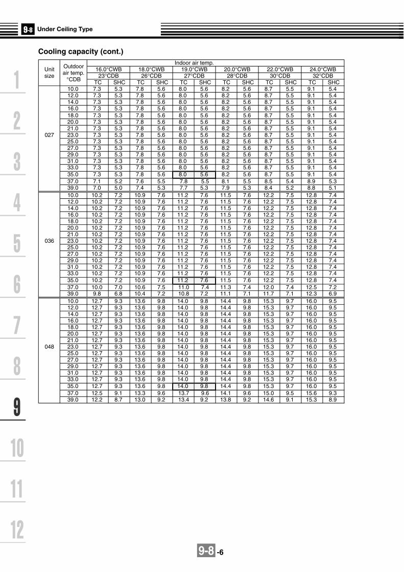
9-8 -6
Cooling capacity (cont.)Indoor air temp.
Unit Outdoor 16.0°CWB 18.0°CWB 19.0°CWB 20.0°CWB 22.0°CWB 24.0°CWBsize air temp. 23°CDB 26°CDB 27°CDB 28°CDB 30°CDB 32°CDB
°CDB TC SHC TC SHC TC SHC TC SHC TC SHC TC SHC10.0 7.3 5.3 7.8 5.6 8.0 5.6 8.2 5.6 8.7 5.5 9.1 5.412.0 7.3 5.3 7.8 5.6 8.0 5.6 8.2 5.6 8.7 5.5 9.1 5.414.0 7.3 5.3 7.8 5.6 8.0 5.6 8.2 5.6 8.7 5.5 9.1 5.416.0 7.3 5.3 7.8 5.6 8.0 5.6 8.2 5.6 8.7 5.5 9.1 5.418.0 7.3 5.3 7.8 5.6 8.0 5.6 8.2 5.6 8.7 5.5 9.1 5.420.0 7.3 5.3 7.8 5.6 8.0 5.6 8.2 5.6 8.7 5.5 9.1 5.421.0 7.3 5.3 7.8 5.6 8.0 5.6 8.2 5.6 8.7 5.5 9.1 5.4
027 23.0 7.3 5.3 7.8 5.6 8.0 5.6 8.2 5.6 8.7 5.5 9.1 5.425.0 7.3 5.3 7.8 5.6 8.0 5.6 8.2 5.6 8.7 5.5 9.1 5.427.0 7.3 5.3 7.8 5.6 8.0 5.6 8.2 5.6 8.7 5.5 9.1 5.429.0 7.3 5.3 7.8 5.6 8.0 5.6 8.2 5.6 8.7 5.5 9.1 5.431.0 7.3 5.3 7.8 5.6 8.0 5.6 8.2 5.6 8.7 5.5 9.1 5.433.0 7.3 5.3 7.8 5.6 8.0 5.6 8.2 5.6 8.7 5.5 9.1 5.435.0 7.3 5.3 7.8 5.6 8.0 5.6 8.2 5.6 8.7 5.5 9.1 5.437.0 7.1 5.2 7.6 5.5 7.8 5.5 8.1 5.5 8.5 5.4 8.9 5.339.0 7.0 5.0 7.4 5.3 7.7 5.3 7.9 5.3 8.4 5.2 8.8 5.110.0 10.2 7.2 10.9 7.6 11.2 7.6 11.5 7.6 12.2 7.5 12.8 7.412.0 10.2 7.2 10.9 7.6 11.2 7.6 11.5 7.6 12.2 7.5 12.8 7.414.0 10.2 7.2 10.9 7.6 11.2 7.6 11.5 7.6 12.2 7.5 12.8 7.416.0 10.2 7.2 10.9 7.6 11.2 7.6 11.5 7.6 12.2 7.5 12.8 7.418.0 10.2 7.2 10.9 7.6 11.2 7.6 11.5 7.6 12.2 7.5 12.8 7.420.0 10.2 7.2 10.9 7.6 11.2 7.6 11.5 7.6 12.2 7.5 12.8 7.421.0 10.2 7.2 10.9 7.6 11.2 7.6 11.5 7.6 12.2 7.5 12.8 7.4
036 23.0 10.2 7.2 10.9 7.6 11.2 7.6 11.5 7.6 12.2 7.5 12.8 7.425.0 10.2 7.2 10.9 7.6 11.2 7.6 11.5 7.6 12.2 7.5 12.8 7.427.0 10.2 7.2 10.9 7.6 11.2 7.6 11.5 7.6 12.2 7.5 12.8 7.429.0 10.2 7.2 10.9 7.6 11.2 7.6 11.5 7.6 12.2 7.5 12.8 7.431.0 10.2 7.2 10.9 7.6 11.2 7.6 11.5 7.6 12.2 7.5 12.8 7.433.0 10.2 7.2 10.9 7.6 11.2 7.6 11.5 7.6 12.2 7.5 12.8 7.435.0 10.2 7.2 10.9 7.6 11.2 7.6 11.5 7.6 12.2 7.5 12.8 7.437.0 10.0 7.0 10.6 7.5 11.0 7.4 11.3 7.4 12.0 7.4 12.5 7.239.0 9.8 6.8 10.4 7.2 10.8 7.2 11.1 7.1 11.7 7.1 12.3 6.910.0 12.7 9.3 13.6 9.8 14.0 9.8 14.4 9.8 15.3 9.7 16.0 9.512.0 12.7 9.3 13.6 9.8 14.0 9.8 14.4 9.8 15.3 9.7 16.0 9.514.0 12.7 9.3 13.6 9.8 14.0 9.8 14.4 9.8 15.3 9.7 16.0 9.516.0 12.7 9.3 13.6 9.8 14.0 9.8 14.4 9.8 15.3 9.7 16.0 9.518.0 12.7 9.3 13.6 9.8 14.0 9.8 14.4 9.8 15.3 9.7 16.0 9.520.0 12.7 9.3 13.6 9.8 14.0 9.8 14.4 9.8 15.3 9.7 16.0 9.521.0 12.7 9.3 13.6 9.8 14.0 9.8 14.4 9.8 15.3 9.7 16.0 9.5
048 23.0 12.7 9.3 13.6 9.8 14.0 9.8 14.4 9.8 15.3 9.7 16.0 9.525.0 12.7 9.3 13.6 9.8 14.0 9.8 14.4 9.8 15.3 9.7 16.0 9.527.0 12.7 9.3 13.6 9.8 14.0 9.8 14.4 9.8 15.3 9.7 16.0 9.529.0 12.7 9.3 13.6 9.8 14.0 9.8 14.4 9.8 15.3 9.7 16.0 9.531.0 12.7 9.3 13.6 9.8 14.0 9.8 14.4 9.8 15.3 9.7 16.0 9.533.0 12.7 9.3 13.6 9.8 14.0 9.8 14.4 9.8 15.3 9.7 16.0 9.535.0 12.7 9.3 13.6 9.8 14.0 9.8 14.4 9.8 15.3 9.7 16.0 9.537.0 12.5 9.1 13.3 9.6 13.7 9.6 14.1 9.6 15.0 9.5 15.6 9.339.0 12.2 8.7 13.0 9.2 13.4 9.2 13.8 9.2 14.6 9.1 15.3 8.9

9-8 -7
SHC : Sensible Heat Capacity (kW)
Unit Outdoor Indoor air temp. °CDB
size air temp. 16.0 18.0 20.0 22.0 24.0
°CWB SHC SHC SHC SHC SHC-15.0 3.1 3.1 3.0 2.9 2.9-13.0 3.3 3.3 3.2 3.1 3.0-11.0 3.6 3.5 3.4 3.3 3.2-10.0 3.7 3.6 3.5 3.4 3.3-8.0 3.9 3.8 3.7 3.6 3.5-6.0 4.1 4.0 3.9 3.8 3.7-4.0 4.3 4.2 4.1 4.0 3.9
015 -2.0 4.5 4.4 4.3 4.2 4.10.0 4.7 4.6 4.5 4.4 4.22.0 4.8 4.7 4.6 4.5 4.44.0 5.0 4.9 4.8 4.7 4.66.0 5.2 5.1 5.0 4.9 4.88.0 5.2 5.1 5.0 4.9 4.8
10.0 5.2 5.1 5.0 4.9 4.812.0 5.2 5.1 5.0 4.9 4.814.0 5.2 5.1 5.0 4.9 4.8-15.0 3.9 3.9 3.8 3.7 3.6-13.0 4.2 4.1 4.0 3.9 3.8-11.0 4.5 4.4 4.3 4.2 4.1-10.0 4.6 4.5 4.4 4.3 4.2-8.0 4.9 4.8 4.7 4.6 4.4-6.0 5.1 5.0 4.9 4.8 4.7-4.0 5.4 5.3 5.2 5.0 4.9
018 -2.0 5.6 5.5 5.4 5.3 5.10.0 5.9 5.8 5.6 5.5 5.32.0 6.1 6.0 5.9 5.7 5.64.0 6.3 6.2 6.1 5.9 5.86.0 6.6 6.4 6.3 6.1 6.08.0 6.6 6.4 6.3 6.1 6.0
10.0 6.6 6.4 6.3 6.1 6.012.0 6.6 6.4 6.3 6.1 6.014.0 6.6 6.4 6.3 6.1 6.0-15.0 5.0 4.9 4.8 4.7 4.6-13.0 5.3 5.2 5.1 5.0 4.9-11.0 5.7 5.6 5.5 5.3 5.2-10.0 5.8 5.7 5.6 5.5 5.3-8.0 6.2 6.1 5.9 5.8 5.6-6.0 6.5 6.4 6.2 6.1 5.9-4.0 6.8 6.7 6.6 6.4 6.2
024 -2.0 7.1 7.0 6.9 6.7 6.50.0 7.4 7.3 7.1 7.0 6.82.0 7.7 7.6 7.4 7.3 7.14.0 8.0 7.9 7.7 7.5 7.36.0 8.3 8.2 8.0 7.8 7.68.0 8.3 8.2 8.0 7.8 7.6
10.0 8.3 8.2 8.0 7.8 7.612.0 8.3 8.2 8.0 7.8 7.614.0 8.3 8.2 8.0 7.8 7.6
Heating capacity

9-8 -8
Unit Outdoor Indoor air temp. °CDB
size air temp. 16.0 18.0 20.0 22.0 24.0°CWB SHC SHC SHC SHC SHC-15.0 5.6 5.5 5.4 5.3 5.1-13.0 6.0 5.9 5.8 5.6 5.5-11.0 6.4 6.3 6.1 6.0 5.8-10.0 6.6 6.5 6.3 6.2 6.0-8.0 7.0 6.8 6.7 6.5 6.3-6.0 7.3 7.2 7.0 6.9 6.7-4.0 7.7 7.5 7.4 7.2 7.0
027 -2.0 8.0 7.9 7.7 7.5 7.30.0 8.4 8.2 8.0 7.8 7.62.0 8.7 8.5 8.4 8.2 7.94.0 9.0 8.9 8.7 8.5 8.36.0 9.4 9.2 9.0 8.8 8.68.0 9.4 9.2 9.0 8.8 8.6
10.0 9.4 9.2 9.0 8.8 8.612.0 9.4 9.2 9.0 8.8 8.614.0 9.4 9.2 9.0 8.8 8.6-15.0 7.8 7.7 7.5 7.3 7.2-13.0 8.3 8.2 8.0 7.8 7.6-11.0 8.9 8.7 8.5 8.3 8.1-10.0 9.1 9.0 8.8 8.6 8.3-8.0 9.7 9.5 9.3 9.1 8.8-6.0 10.2 10.0 9.8 9.5 9.3-4.0 10.7 10.5 10.2 10.0 9.7
036 -2.0 11.1 10.9 10.7 10.5 10.20.0 11.6 11.4 11.2 10.9 10.62.0 12.1 11.9 11.6 11.3 11.04.0 12.6 12.3 12.1 11.8 11.56.0 13.0 12.8 12.5 12.2 11.98.0 13.0 12.8 12.5 12.2 11.9
10.0 13.0 12.8 12.5 12.2 11.912.0 13.0 12.8 12.5 12.2 11.914.0 13.0 12.8 12.5 12.2 11.9-15.0 10.0 9.8 9.6 9.4 9.1-13.0 10.7 10.5 10.3 10.0 9.7-11.0 11.4 11.1 10.9 10.7 10.4-10.0 11.7 11.5 11.2 11.0 10.7-8.0 12.4 12.1 11.9 11.6 11.3-6.0 13.0 12.8 12.5 12.2 11.9-4.0 13.6 13.4 13.1 12.8 12.4
048 -2.0 14.3 14.0 13.7 13.4 13.00.0 14.9 14.6 14.3 14.0 13.62.0 15.5 15.2 14.9 14.5 14.14.0 16.1 15.8 15.4 15.1 14.76.0 16.7 16.3 16.0 15.6 15.28.0 16.7 16.3 16.0 15.6 15.2
10.0 16.7 16.3 16.0 15.6 15.212.0 16.7 16.3 16.0 15.6 15.214.0 16.7 16.3 16.0 15.6 15.2
Heating capacity (cont.)

9-8 -9
9-8-5. Air throw distance chart
1m
1m 2m 3m 4m 1m 2m 3m 4m
1m 2m 3m 4m
2m
3m0.3
0.5
1.0
0.3 0.5
1m
2m
3m
1m
2m
3m
0.3
0.5
1.0
0.3
0.3
0.5
1.0
0.3
MMC-AP0181H,AP0481H MMC-AP0361H
MMC-AP015H,AP0241H,AP0271H

9-8 -10
9-8-6. Sound characteristics (NC-Curve)
Sound level values shown are based on a measurement in a non resound room.
10
20
30
40
50
60
70
80
90
NC-70
NC-60
NC-50
NC-40
NC-30
NC-20
20~
75
75~
150
150~
300
300~
600
600~
1200
1200~
2400
2400~
4800
4800~
9600
HML
10
20
30
40
50
60
70
80
90
NC-70
NC-60
NC-50
NC-40
NC-30
NC-20
20~
75
75~
150
150~
300
300~
600
600~
1200
1200~
2400
2400~
4800
4800~
9600
HML
10
20
30
40
50
60
70
80
90
NC-70
NC-60
NC-50
NC-40
NC-30
NC-20
20~
75
75~
150
150~
300
300~
600
600~
1200
1200~
2400
2400~
4800
4800~
9600
HML
10
20
30
40
50
60
70
80
90
NC-70
NC-60
NC-50
NC-40
NC-30
NC-20
20~
75
75~
150
150~
300
300~
600
600~
1200
1200~
2400
2400~
4800
4800~
9600
HML
10
20
30
40
50
60
70
80
90
NC-70
NC-60
NC-50
NC-40
NC-30
NC-20
20~
75
75~
150
150~
300
300~
600
600~
1200
1200~
2400
2400~
4800
4800~
9600
HML
Microphone
MMC-AP0151HFan Tap
Sound pressurelevel (dB(A))
H
35
M
32
L
30
Oct
ave
ban
d s
ou
nd
pre
ssu
re l
evel
(d
B)
Octave band frequency (Hz)
Audibility limits ofcontinuous white level
MMC-AP0181HFan Tap
Sound pressurelevel (dB(A))
H
36
M
33
L
30
MMC-AP0241H,AP0271HFan Tap
Sound pressurelevel (dB(A))
H
38
M
36
L
33
MMC-AP0361HFan Tap
Sound pressurelevel (dB(A))
H
41
M
38
L
35
MMC-AP0481HFan Tap
Sound pressurelevel (dB(A))
H
43
M
40
L
37
Oct
ave
ban
d s
ou
nd
pre
ssu
re l
evel
(d
B)
Oct
ave
ban
d s
ou
nd
pre
ssu
re l
evel
(d
B)
Oct
ave
ban
d s
ou
nd
pre
ssu
re l
evel
(d
B)
Oct
ave
ban
d s
ou
nd
pre
ssu
re l
evel
(d
B)
Octave band frequency (Hz) Octave band frequency (Hz)
Octave band frequency (Hz) Octave band frequency (Hz)
Audibility limits ofcontinuous white level
Audibility limits ofcontinuous white level
Audibility limits ofcontinuous white level
Audibility limits ofcontinuous white level

9-8 -11
9-8-7. Accessories
Apperarance
Standard accessories
Remote controller
Weekly timer application
Model Name
RBC-AMT31E
RBC-AS21E2
TCB-AX21E2
RBC-AMT31E and RBC-EXW21E2
Wired remote controller
TCB-SC642TLE2
TCB-CC163TLE2
Simple wired remote controller
Wireless remote controller kit
Central remote controller
ON-OFF controller
Part name Qty Shape Use Part name Qty Shape Use
Installation Manual 1 (Be sure to hand over to the
customer) Heat insulator 1 For heat insulation of drain
connecting section
Heat insulating pipe
2 For heat insulation of pipe connecting section Washer 4 For hanging-down unit
Installation pattern 1
For confirmation of ceiling opening and main unit position
Hose band 2 For connecting drain pipe
Banding band 2 For drain hose forming Drain hose 1 For drain piping
Bushing For power supply cord protection
Heat insulator 1 For sealing of piping hole 1

9-8 -12
Optional accessories
Drain pump kit
TCB-DP22CE2
Elbow piping kit
TCB-KP12CE2TCB-KP22CE2
Name Model name Note
Stand-up 600 or less(from bottom face of ceiling)MMC-AP0151/0181H Type(Use with TCB-KP12CE)MMC-AP0241H/0271/0361H/0481H (Use with TCB-KP22CE)
Needed when Drain Pump Kid is used
TCB-DP22CE
TCB-KP12CE
TCB-KP22CE
Drain Pump Kit
Elbow Piping Kit

9-9 -1
9-9-1. Specifications 50Hz
Specifications (50Hz)
Note 1 : The cooling capacities and electrical characteristics are measured under the conditions specified by JIS B 8615 based on thereference piping. The reference piping consists of 5 m of main piping and 2.5 m of branch piping connected with 0 meter height.
Note 2 : The sound level are measured in an anechoic chamber in accordance with JIS B8616. Normally, the values measured in theactual operating environment become larger than the indicated values due to the effects of external sound.
Note : Rated conditions Cooling : Indoor air temperature 27oC DB/19oC WB, Outdoor air temperature 35oC DBHeating : Indoor air temperature 20oC DB, Outdoor air temperature 7oC DB/6oC WB
Cooling/Heating capacity (Note 1) (kW)
Electricalcharacteristics
Power supply
Running current (A)
Power consumption (kW)
Starting current (A)
Suction grille and side panel
Discharge grille
Bottom surface
Model name MMK-
Appearance
Outerdimension
Height x Width x Depth (mm)
Total weight (kg)
Heat exchanger
Soundproof/Heat-insulating material
Fan unit
Fan
Standard air flow (High/Mid/Low)
(m3/h)
Motor outlet (W)
Air filter
Controller
Gas side (mm)
Liquid side (mm)
Drain port (Nominal dia. mm)
Connectingpipe
Sound pressure level (Note 2)(High/Mid/Low) (dB(A))
AP0071H
2.2/2.5
1 phase 50Hz 230V (220-240V) (Separate power supply for indoor units is required.)
0.30
0.035
0.36
AP0091H
2.8/3.2
AP0121H
3.6/4.0
AP0151H
4.5/5.0
AP0181H
5.6/6.3
AP0241H
7.1/8.0
0.35
0.040
0.47
0.32
0.037
0.42
Silky mist (Munsell 1Y 8.9/0.5)
City gray (Munsell N6.5)
Silky mist (Munsell 1Y 8.9/0.5)
368 x 895 x 210 368 x 1,055 x 210 368 x 1,430 x 210
18 2519
Finned tube
Non-flammable insulation
Cross-flow fan
600/540/480 780/660/600 1,200/1,020/900
30
Standard filter (Simple filter)
Remote controller
O/ 9.5 O/ 12.7 O/ 15.9
O/ 9.5O/ 6.4
20 (Polyvinyl chloride tube)
39/34/31 42/38/35 42/38/35
PMV Kit Available
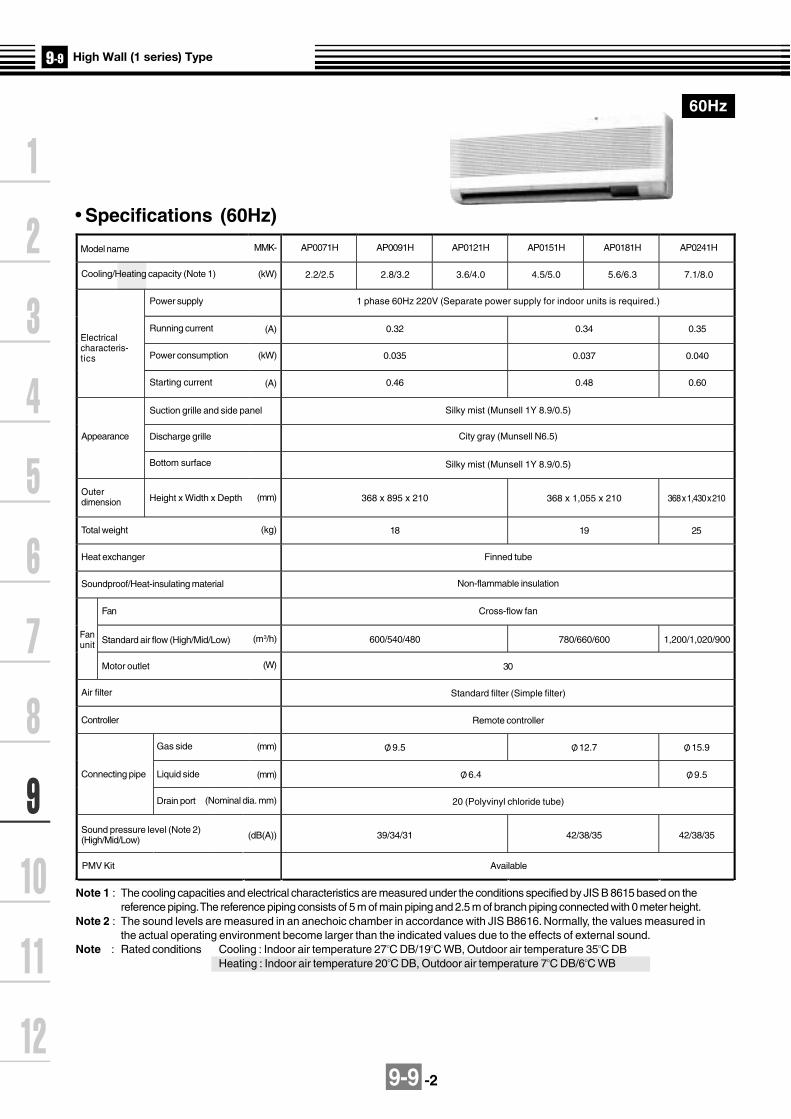
9-9 -2
60Hz
Specifications (60Hz)
Model name
Cooling/Heating capacity (Note 1)
AP0071H
2.2/2.5
Power supply
Electricalcharacteris-tics
Running current (A)
Power consumption
Starting current
Suction grille and side panel
Discharge grille
Bottom surface
Appearance
Outerdimension Height x Width x Depth
Total weight
Heat exchanger
Soundproof/Heat-insulating material
Fanunit
Fan
Standard air flow (High/Mid/Low)
Motor outlet
Air filter
Controller
Connecting pipe
Gas side
Liquid side
Drain port
Sound pressure level (Note 2)(High/Mid/Low)
MMK-
(kW)
(kW)
(A)
(mm)
(kg)
(W)
(m3/h)
(mm)
(mm)
(Nominal dia. mm)
(dB(A))
AP0091H
2.8/3.2
AP0121H
3.6/4.0
AP0151H
4.5/5.0
AP0181H
5.6/6.3
AP0241H
7.1/8.0
1 phase 60Hz 220V (Separate power supply for indoor units is required.)
0.32 0.34 0.35
0.035 0.037 0.040
0.46 0.48 0.60
Silky mist (Munsell 1Y 8.9/0.5)
City gray (Munsell N6.5)
Silky mist (Munsell 1Y 8.9/0.5)
368 x 895 x 210 368 x 1,055 x 210 368 x 1,430 x 210
18 19 25
Finned tube
Non-flammable insulation
Cross-flow fan
600/540/480 780/660/600 1,200/1,020/900
30
Remote controller
Standard filter (Simple filter)
O/ 9.5 O/ 12.7 O/ 15.9
O/ 6.4 O/ 9.5
20 (Polyvinyl chloride tube)
39/34/31 42/38/35 42/38/35
Note 1 : The cooling capacities and electrical characteristics are measured under the conditions specified by JIS B 8615 based on thereference piping. The reference piping consists of 5 m of main piping and 2.5 m of branch piping connected with 0 meter height.
Note 2 : The sound levels are measured in an anechoic chamber in accordance with JIS B8616. Normally, the values measured inthe actual operating environment become larger than the indicated values due to the effects of external sound.
Note : Rated conditions Cooling : Indoor air temperature 27OC DB/19OC WB, Outdoor air temperature 35OC DBHeating : Indoor air temperature 20OC DB, Outdoor air temperature 7OC DB/6OC WB
PMV Kit Available

9-9 -3
MMK-AP0071H, AP0091H, AP0121H
9-9-2. Dimension
9.5
690 (Installation plate)
Upper end of installation plate
Discharge port(Air direction upward/downward/leftward/rightward are adjustable.)
Air suction port
Gas pipe 440Liquid pipe 540Drain pipe 560
Long hole for wooden screw15-6 X 30
Hole for anchor bolt10-10 X 20 long hole
16
4 2.7
120
120
Piping port from left/right sides(Knockout hole)
(Including installation plate)210
Including installation plate (Accessory)
Earth screw (M4)(Inside of electric parts box)
Refrigerant pipe connecting portGas side O/ 9.5
Refrigerant pipe connecting portLiquid side O/ 6.4
Drain pipe connecting port
300 or more 300 or more
30 o
r m
ore
At shipment(When drawing pipe from left)
Space required for service
Position of holes on the installation plate.
Note: All dimensions are in mm.
Wired remote controller RBC-AMT31E
Simple wired remote controller RBC-AS21E2
Wireless remote controller kit TCB-AX21E2
Weekly timer application RBC-AMT31E and RBC-EXW21E2

9-9 -4
MMK-AP0151H, AP0181H
690 (Installation plate)182.5 182.5
Upper end of installation plate
Gas pipe 440Liquid pipe 540Drain pipe 560
At shipment(When drawing pipe from left)
Hole for wooden screw15-6 X 30
Hole for anchor bolt10-10 X 20 long hole
Piping port from left/right sides(Knockout hole)
(Including installation plate)210
Including installation plate (Accessory)
Earth screw (M4)(Inside of electric parts box)
Refrigerant pipe connecting portGas side O/ 12.7
Refrigerant pipe connecting portLiquid side O/ 6.4
Drain pipe connecting port
300 or more 300 or more
30 o
r m
ore
Air discharge port(Air direction upward/downward/leftward/rightward air adjustable.)
Air suction port
Space required for service
Note: All dimensions are in mm.
Wired remote controller RBC-AMT31E
Simple wired remote controller RBC-AS21E2
Wireless remote controller kit TCB-AX21E2
Weekly timer application RBC-AMT31E and RBC-EXW21E2
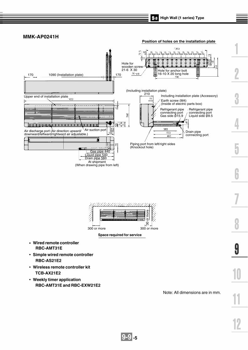
9-9 -5
1090 (Installation plate)170 170
Upper end of installation plate
Air discharge port (Air direction upward/downward/leftward/rightward air adjustable.)
Air suction port
Gas pipe 440Liquid pipe 540Drain pipe 560
At shipment(When drawing pipe from left)
Hole for wooden screw21-6 X 30
Position of holes on the installation plate
Hole for anchor bolt16-10 X 20 long hole
Piping port from left/right sides(Knockout hole)
(Including installation plate)210
Including installation plate (Accessory)
Earth screw (M4)(Inside of electric parts box)
Refrigerant pipe connecting portGas side O/ 15.9
Refrigerant pipe connecting portLiquid side O/ 9.5
Drain pipe connecting port
300 or more 300 or more
30 o
r m
ore
MMK-AP0241H
Space required for service
Note: All dimensions are in mm.
Wired remote controller RBC-AMT31E
Simple wired remote controller RBC-AS21E2
Wireless remote controller kit TCB-AX21E2
Weekly timer application RBC-AMT31E and RBC-EXW21E2

9-9-6
CN080(GRN)
EXCT
23
1
CN68(BLU)
3
1
CN304(GRY)
3
1
3
1
CN67(BLK)
CN66(WHI)
3
1
21
3
1
CN103(GRN) 2
1
CN73(RED) 2
1
CN70(WHI) 2
1
11
2 31 2 3 4 53
CN100(BRW)
CN101(BLK)
CN34(RED)
CN33(WHI)
1 2 3 4 5
CN20(BLU)
1 2 3 4 5
CN81(BLK)
1 2 3 4 5 6
CN60(WHI)
1 2 3 4 5 6
CN61(YEL)
1 2 31 31 3
1 21 21 2
31 3
4 5
CN50(WHI)
CN41(BLU)
CN40(BLU)
GRY
BLUBLU
BLKBLK
BLK
WHI
GRY
CN309(YEL) Option
1 2
CN32(WHI)
Fandrive
CN82(BLU)
Motor drivecircuit
CN333(WHI)
CN334(WHI)
TC1TC2
CN102(RED)
TCJ
21
21
21
21
21
21
CN104(YEL)
TA
11
33
1 2 3 4 5 61
11 2 3 4 5 6
1 234 561 234 56
22
344
55
1 3 51 3
1 2 31 2 3
5
PMV11
54
54
LM
P301BLK
RY302
FUSET6.3A 250V~
RY303
11
22
11
22
32
1 1
3CN01(WHI)
CN03(RED)
CN02(BLU)
TR
11
22
Network Adapter(Option)
MCC-1401
U1 U2
U1 U2
A B X Y
CN1(WHI)
WHI BLK
Wired remotecontroller
Outdoorunit
11
22
CN001(WHI)
WHI BLK
Adapter forwireless remote
controller
Power supplysingle phase
220-240V 50Hz220V 60Hz
Indoor unit
Earth screw
Closed-endconnector
RED
WHI
R(L) S(N)
FM
FUSET3.15A 250V~
Powersupplycircuit
DC20VDC15VDC12VDC7V
Flow selector unit earth
screw
RED
WHI
Symbol
FM
TA
TC1,TC2,TCJ
PMV
LM
RY303
Parts name
Fan motor
Indoor temp sensor
Temp sensor
Pulse motor valve
Lover motor
Louver control relay
Colorindication
RED : REDWHI : WHITEYEL : YELLOWBLU : BLUEBLK : BLACKGRY : GRAYPNK : PINKORN :ORANGEBRN : BROWNGRN : GREEN
Control P.C. boardfor Indoor unit
MCC-1402
1. indicates the terminal block, the letter inside
indicates the terminal number.
2. A dotted line and broken line indicate the wiring on site.
3. indicates the control P.C. board.
9-9-3. Wirin
g d
iagram
Mo
del: M
MK
-AP
0071H, A
P0091H
, AP
0121H, A
P0151H
, AP
0181H, A
P0241H

9-9 -7
TC : Total Capacity (kW) SHC : Sensible Heat Capacity (kW)Indoor air temp.
Unit Outdoor 16.0°CWB 18.0°CWB 19.0°CWB 20.0°CWB 22.0°CWB 24.0°CWBsize air temp. 23°CDB 26°CDB 27°CDB 28°CDB 30°CDB 32°CDB
°CDB TC SHC TC SHC TC SHC TC SHC TC SHC TC SHC10.0 2.0 1.6 2.1 1.7 2.2 1.7 2.3 1.7 2.4 1.7 2.5 1.612.0 2.0 1.6 2.1 1.7 2.2 1.7 2.3 1.7 2.4 1.7 2.5 1.614.0 2.0 1.6 2.1 1.7 2.2 1.7 2.3 1.7 2.4 1.7 2.5 1.616.0 2.0 1.6 2.1 1.7 2.2 1.7 2.3 1.7 2.4 1.7 2.5 1.618.0 2.0 1.6 2.1 1.7 2.2 1.7 2.3 1.7 2.4 1.7 2.5 1.620.0 2.0 1.6 2.1 1.7 2.2 1.7 2.3 1.7 2.4 1.7 2.5 1.621.0 2.0 1.6 2.1 1.7 2.2 1.7 2.3 1.7 2.4 1.7 2.5 1.6
007 23.0 2.0 1.6 2.1 1.7 2.2 1.7 2.3 1.7 2.4 1.7 2.5 1.625.0 2.0 1.6 2.1 1.7 2.2 1.7 2.3 1.7 2.4 1.7 2.5 1.627.0 2.0 1.6 2.1 1.7 2.2 1.7 2.3 1.7 2.4 1.7 2.5 1.629.0 2.0 1.6 2.1 1.7 2.2 1.7 2.3 1.7 2.4 1.7 2.5 1.631.0 2.0 1.6 2.1 1.7 2.2 1.7 2.3 1.7 2.4 1.7 2.5 1.633.0 2.0 1.6 2.1 1.7 2.2 1.7 2.3 1.7 2.4 1.7 2.5 1.635.0 2.0 1.6 2.1 1.7 2.2 1.7 2.3 1.7 2.4 1.7 2.5 1.637.0 2.0 1.6 2.1 1.7 2.2 1.7 2.2 1.7 2.4 1.7 2.5 1.639.0 1.9 1.5 2.0 1.6 2.1 1.6 2.2 1.6 2.3 1.6 2.4 1.510.0 2.5 1.9 2.7 2.0 2.8 2.0 2.9 2.0 3.1 2.0 3.2 1.912.0 2.5 1.9 2.7 2.0 2.8 2.0 2.9 2.0 3.1 2.0 3.2 1.914.0 2.5 1.9 2.7 2.0 2.8 2.0 2.9 2.0 3.1 2.0 3.2 1.916.0 2.5 1.9 2.7 2.0 2.8 2.0 2.9 2.0 3.1 2.0 3.2 1.918.0 2.5 1.9 2.7 2.0 2.8 2.0 2.9 2.0 3.1 2.0 3.2 1.920.0 2.5 1.9 2.7 2.0 2.8 2.0 2.9 2.0 3.1 2.0 3.2 1.921.0 2.5 1.9 2.7 2.0 2.8 2.0 2.9 2.0 3.1 2.0 3.2 1.9
009 23.0 2.5 1.9 2.7 2.0 2.8 2.0 2.9 2.0 3.1 2.0 3.2 1.925.0 2.5 1.9 2.7 2.0 2.8 2.0 2.9 2.0 3.1 2.0 3.2 1.927.0 2.5 1.9 2.7 2.0 2.8 2.0 2.9 2.0 3.1 2.0 3.2 1.929.0 2.5 1.9 2.7 2.0 2.8 2.0 2.9 2.0 3.1 2.0 3.2 1.931.0 2.5 1.9 2.7 2.0 2.8 2.0 2.9 2.0 3.1 2.0 3.2 1.933.0 2.5 1.9 2.7 2.0 2.8 2.0 2.9 2.0 3.1 2.0 3.2 1.935.0 2.5 1.9 2.7 2.0 2.8 2.0 2.9 2.0 3.1 2.0 3.2 1.937.0 2.5 1.9 2.7 2.0 2.7 2.0 2.8 2.0 3.0 1.9 3.1 1.939.0 2.4 1.8 2.6 1.9 2.7 1.9 2.8 1.9 2.9 1.9 3.1 1.810.0 3.3 2.4 3.5 2.5 3.6 2.5 3.7 2.5 3.9 2.5 4.1 2.412.0 3.3 2.4 3.5 2.5 3.6 2.5 3.7 2.5 3.9 2.5 4.1 2.414.0 3.3 2.4 3.5 2.5 3.6 2.5 3.7 2.5 3.9 2.5 4.1 2.416.0 3.3 2.4 3.5 2.5 3.6 2.5 3.7 2.5 3.9 2.5 4.1 2.418.0 3.3 2.4 3.5 2.5 3.6 2.5 3.7 2.5 3.9 2.5 4.1 2.420.0 3.3 2.4 3.5 2.5 3.6 2.5 3.7 2.5 3.9 2.5 4.1 2.421.0 3.3 2.4 3.5 2.5 3.6 2.5 3.7 2.5 3.9 2.5 4.1 2.4
012 23.0 3.3 2.4 3.5 2.5 3.6 2.5 3.7 2.5 3.9 2.5 4.1 2.425.0 3.3 2.4 3.5 2.5 3.6 2.5 3.7 2.5 3.9 2.5 4.1 2.427.0 3.3 2.4 3.5 2.5 3.6 2.5 3.7 2.5 3.9 2.5 4.1 2.429.0 3.3 2.4 3.5 2.5 3.6 2.5 3.7 2.5 3.9 2.5 4.1 2.431.0 3.3 2.4 3.5 2.5 3.6 2.5 3.7 2.5 3.9 2.5 4.1 2.433.0 3.3 2.4 3.5 2.5 3.6 2.5 3.7 2.5 3.9 2.5 4.1 2.435.0 3.3 2.4 3.5 2.5 3.6 2.5 3.7 2.5 3.9 2.5 4.1 2.437.0 3.2 2.3 3.4 2.5 3.5 2.5 3.6 2.4 3.8 2.4 4.0 2.439.0 3.1 2.2 3.4 2.4 3.5 2.4 3.6 2.4 3.8 2.3 3.9 2.3
9-9-4. Sensible capacity table(MMD-AP***H)
Cooling capacity

9-9 -8
Cooling capacity (cont.)Indoor air temp.
Unit Outdoor 16.0°CWB 18.0°CWB 19.0°CWB 20.0°CWB 22.0°CWB 24.0°CWBsize air temp. 23°CDB 26°CDB 27°CDB 28°CDB 30°CDB 32°CDB
°CDB TC SHC TC SHC TC SHC TC SHC TC SHC TC SHC10.0 4.1 2.7 4.4 2.9 4.5 2.9 4.6 2.9 4.9 2.9 5.1 2.812.0 4.1 2.7 4.4 2.9 4.5 2.9 4.6 2.9 4.9 2.9 5.1 2.814.0 4.1 2.7 4.4 2.9 4.5 2.9 4.6 2.9 4.9 2.9 5.1 2.816.0 4.1 2.7 4.4 2.9 4.5 2.9 4.6 2.9 4.9 2.9 5.1 2.818.0 4.1 2.7 4.4 2.9 4.5 2.9 4.6 2.9 4.9 2.9 5.1 2.820.0 4.1 2.7 4.4 2.9 4.5 2.9 4.6 2.9 4.9 2.9 5.1 2.821.0 4.1 2.7 4.4 2.9 4.5 2.9 4.6 2.9 4.9 2.9 5.1 2.8
015 23.0 4.1 2.7 4.4 2.9 4.5 2.9 4.6 2.9 4.9 2.9 5.1 2.825.0 4.1 2.7 4.4 2.9 4.5 2.9 4.6 2.9 4.9 2.9 5.1 2.827.0 4.1 2.7 4.4 2.9 4.5 2.9 4.6 2.9 4.9 2.9 5.1 2.829.0 4.1 2.7 4.4 2.9 4.5 2.9 4.6 2.9 4.9 2.9 5.1 2.831.0 4.1 2.7 4.4 2.9 4.5 2.9 4.6 2.9 4.9 2.9 5.1 2.833.0 4.1 2.7 4.4 2.9 4.5 2.9 4.6 2.9 4.9 2.9 5.1 2.835.0 4.1 2.7 4.4 2.9 4.5 2.9 4.6 2.9 4.9 2.9 5.1 2.837.0 4.0 2.7 4.3 2.9 4.4 2.8 4.5 2.8 4.8 2.8 5.0 2.839.0 3.9 2.6 4.2 2.7 4.3 2.7 4.4 2.7 4.7 2.7 4.9 2.610.0 5.1 3.4 5.4 3.6 5.6 3.6 5.8 3.6 6.1 3.6 6.4 3.512.0 5.1 3.4 5.4 3.6 5.6 3.6 5.8 3.6 6.1 3.6 6.4 3.514.0 5.1 3.4 5.4 3.6 5.6 3.6 5.8 3.6 6.1 3.6 6.4 3.516.0 5.1 3.4 5.4 3.6 5.6 3.6 5.8 3.6 6.1 3.6 6.4 3.518.0 5.1 3.4 5.4 3.6 5.6 3.6 5.8 3.6 6.1 3.6 6.4 3.520.0 5.1 3.4 5.4 3.6 5.6 3.6 5.8 3.6 6.1 3.6 6.4 3.521.0 5.1 3.4 5.4 3.6 5.6 3.6 5.8 3.6 6.1 3.6 6.4 3.5
018 23.0 5.1 3.4 5.4 3.6 5.6 3.6 5.8 3.6 6.1 3.6 6.4 3.525.0 5.1 3.4 5.4 3.6 5.6 3.6 5.8 3.6 6.1 3.6 6.4 3.527.0 5.1 3.4 5.4 3.6 5.6 3.6 5.8 3.6 6.1 3.6 6.4 3.529.0 5.1 3.4 5.4 3.6 5.6 3.6 5.8 3.6 6.1 3.6 6.4 3.531.0 5.1 3.4 5.4 3.6 5.6 3.6 5.8 3.6 6.1 3.6 6.4 3.533.0 5.1 3.4 5.4 3.6 5.6 3.6 5.8 3.6 6.1 3.6 6.4 3.535.0 5.1 3.4 5.4 3.6 5.6 3.6 5.8 3.6 6.1 3.6 6.4 3.537.0 5.0 3.3 5.3 3.5 5.5 3.5 5.7 3.5 6.0 3.5 6.3 3.439.0 4.9 3.2 5.2 3.4 5.4 3.4 5.5 3.4 5.9 3.4 6.1 3.310.0 6.4 4.4 6.9 4.7 7.1 4.7 7.3 4.7 7.7 4.7 8.1 4.512.0 6.4 4.4 6.9 4.7 7.1 4.7 7.3 4.7 7.7 4.7 8.1 4.514.0 6.4 4.4 6.9 4.7 7.1 4.7 7.3 4.7 7.7 4.7 8.1 4.516.0 6.4 4.4 6.9 4.7 7.1 4.7 7.3 4.7 7.7 4.7 8.1 4.518.0 6.4 4.4 6.9 4.7 7.1 4.7 7.3 4.7 7.7 4.7 8.1 4.520.0 6.4 4.4 6.9 4.7 7.1 4.7 7.3 4.7 7.7 4.7 8.1 4.521.0 6.4 4.4 6.9 4.7 7.1 4.7 7.3 4.7 7.7 4.7 8.1 4.5
024 23.0 6.4 4.4 6.9 4.7 7.1 4.7 7.3 4.7 7.7 4.7 8.1 4.525.0 6.4 4.4 6.9 4.7 7.1 4.7 7.3 4.7 7.7 4.7 8.1 4.527.0 6.4 4.4 6.9 4.7 7.1 4.7 7.3 4.7 7.7 4.7 8.1 4.529.0 6.4 4.4 6.9 4.7 7.1 4.7 7.3 4.7 7.7 4.7 8.1 4.531.0 6.4 4.4 6.9 4.7 7.1 4.7 7.3 4.7 7.7 4.7 8.1 4.533.0 6.4 4.4 6.9 4.7 7.1 4.7 7.3 4.7 7.7 4.7 8.1 4.535.0 6.4 4.4 6.9 4.7 7.1 4.7 7.3 4.7 7.7 4.7 8.1 4.537.0 6.3 4.3 6.7 4.6 7.0 4.6 7.2 4.6 7.6 4.6 7.9 4.539.0 6.2 4.2 6.6 4.4 6.8 4.4 7.0 4.4 7.4 4.4 7.8 4.3

9-9 -9
SHC : Sensible Heat Capacity (kW)
UnitOutdoor Indoor air temp. °CDB
size air temp. 16.0 18.0 20.0 22.0 24.0
°CWB SHC SHC SHC SHC SHC-15.0 1.6 1.5 1.5 1.5 1.4-13.0 1.7 1.6 1.6 1.6 1.5-11.0 1.8 1.7 1.7 1.7 1.6-10.0 1.8 1.8 1.8 1.7 1.7-8.0 1.9 1.9 1.9 1.8 1.8-6.0 2.0 2.0 2.0 1.9 1.9-4.0 2.1 2.1 2.0 2.0 1.9
007 -2.0 2.2 2.2 2.1 2.1 2.00.0 2.3 2.3 2.2 2.2 2.12.0 2.4 2.4 2.3 2.3 2.24.0 2.5 2.5 2.4 2.4 2.36.0 2.6 2.6 2.5 2.4 2.48.0 2.6 2.6 2.5 2.4 2.4
10.0 2.6 2.6 2.5 2.4 2.412.0 2.6 2.6 2.5 2.4 2.414.0 2.6 2.6 2.5 2.4 2.4-15.0 2.0 2.0 1.9 1.9 1.8-13.0 2.1 2.1 2.1 2.0 1.9-11.0 2.3 2.2 2.2 2.1 2.1-10.0 2.3 2.3 2.2 2.2 2.1-8.0 2.5 2.4 2.4 2.3 2.3-6.0 2.6 2.6 2.5 2.4 2.4-4.0 2.7 2.7 2.6 2.6 2.5
009 -2.0 2.9 2.8 2.7 2.7 2.60.0 3.0 2.9 2.9 2.8 2.72.0 3.1 3.0 3.0 2.9 2.84.0 3.2 3.2 3.1 3.0 2.96.0 3.3 3.3 3.2 3.1 3.08.0 3.3 3.3 3.2 3.1 3.0
10.0 3.3 3.3 3.2 3.1 3.012.0 3.3 3.3 3.2 3.1 3.014.0 3.3 3.3 3.2 3.1 3.0-15.0 2.5 2.5 2.4 2.3 2.3-13.0 2.7 2.6 2.6 2.5 2.4-11.0 2.8 2.8 2.7 2.7 2.6-10.0 2.9 2.9 2.8 2.7 2.7-8.0 3.1 3.0 3.0 2.9 2.8-6.0 3.3 3.2 3.1 3.0 3.0-4.0 3.4 3.3 3.3 3.2 3.1
012 -2.0 3.6 3.5 3.4 3.3 3.30.0 3.7 3.7 3.6 3.5 3.42.0 3.9 3.8 3.7 3.6 3.54.0 4.0 3.9 3.9 3.8 3.76.0 4.2 4.1 4.0 3.9 3.88.0 4.2 4.1 4.0 3.9 3.8
10.0 4.2 4.1 4.0 3.9 3.812.0 4.2 4.1 4.0 3.9 3.814.0 4.2 4.1 4.0 3.9 3.8
Heating capacity

9-9 -10
Unit Outdoor Indoor air temp. °CDB
size air temp. 16.0 18.0 20.0 22.0 24.0
°CWB SHC SHC SHC SHC SHC-15.0 3.1 3.1 3.0 2.9 2.9-13.0 3.3 3.3 3.2 3.1 3.0-11.0 3.6 3.5 3.4 3.3 3.2-10.0 3.7 3.6 3.5 3.4 3.3-8.0 3.9 3.8 3.7 3.6 3.5-6.0 4.1 4.0 3.9 3.8 3.7-4.0 4.3 4.2 4.1 4.0 3.9
015 -2.0 4.5 4.4 4.3 4.2 4.10.0 4.7 4.6 4.5 4.4 4.22.0 4.8 4.7 4.6 4.5 4.44.0 5.0 4.9 4.8 4.7 4.66.0 5.2 5.1 5.0 4.9 4.88.0 5.2 5.1 5.0 4.9 4.8
10.0 5.2 5.1 5.0 4.9 4.812.0 5.2 5.1 5.0 4.9 4.814.0 5.2 5.1 5.0 4.9 4.8-15.0 3.9 3.9 3.8 3.7 3.6-13.0 4.2 4.1 4.0 3.9 3.8-11.0 4.5 4.4 4.3 4.2 4.1-10.0 4.6 4.5 4.4 4.3 4.2-8.0 4.9 4.8 4.7 4.6 4.4-6.0 5.1 5.0 4.9 4.8 4.7-4.0 5.4 5.3 5.2 5.0 4.9
018 -2.0 5.6 5.5 5.4 5.3 5.10.0 5.9 5.8 5.6 5.5 5.32.0 6.1 6.0 5.9 5.7 5.64.0 6.3 6.2 6.1 5.9 5.86.0 6.6 6.4 6.3 6.1 6.08.0 6.6 6.4 6.3 6.1 6.0
10.0 6.6 6.4 6.3 6.1 6.012.0 6.6 6.4 6.3 6.1 6.014.0 6.6 6.4 6.3 6.1 6.0-15.0 5.0 4.9 4.8 4.7 4.6-13.0 5.3 5.2 5.1 5.0 4.9-11.0 5.7 5.6 5.5 5.3 5.2-10.0 5.8 5.7 5.6 5.5 5.3-8.0 6.2 6.1 5.9 5.8 5.6-6.0 6.5 6.4 6.2 6.1 5.9-4.0 6.8 6.7 6.6 6.4 6.2
024 -2.0 7.1 7.0 6.9 6.7 6.50.0 7.4 7.3 7.1 7.0 6.82.0 7.7 7.6 7.4 7.3 7.14.0 8.0 7.9 7.7 7.5 7.36.0 8.3 8.2 8.0 7.8 7.68.0 8.3 8.2 8.0 7.8 7.6
10.0 8.3 8.2 8.0 7.8 7.612.0 8.3 8.2 8.0 7.8 7.614.0 8.3 8.2 8.0 7.8 7.6
Heating capacity (cont.)

9-9 -11
0 1 2 3 4 5 6 7
1
2
3
4
5
0 1 2 3 4 5 6 7
1
2
3
4
5
0 1 2 3 4 5 6 7
1
2
3
4
5
9-9-5. Air throw distance chart
MMK-AP0241H
MMK-AP0071H, AP0091H, AP0121H MMK-AP0151H, AP0181H
Horizontal discharge Initial speed
Air
spee
d (m
/s)
High wind: 5.0m/sMed. wind: 4.4m/s
Horizontal throw (m)
Horizontal discharge Initial speed
Air
spee
d (m
/s)
High wind: 5.0m/sMed. wind: 4.4m/s
Horizontal throw (m)
Horizontal discharge Initial speed
Air
spee
d (m
/s)
High wind: 5.0m/sMed. wind: 4.4m/s
Horizontal throw (m)
(Revised 07 Apr 2006)

9-9 -12
9-9-6. Sound characteristics (NC-Curve)
NC-70
NC-60
NC-50
NC-40
NC-30
NC-20
MM
L
10
20
30
40
50
60
70
80
90
60 125 250 500 1000 2000 4000 8000
NC-70
NC-60
NC-50
NC-40
NC-30
NC-20
H
M
L
10
20
30
40
50
60
70
80
90
63
NC-70
NC-60
NC-50
NC-40
NC-30
NC-20
HM
L
10
20
30
40
50
60
70
80
90
63 125 250 500 1000 2000 4000 8000
Microphone
MMK-AP0071H, AP0091H, AP0121H
Oct
ave
band
sou
nd p
ress
ure
leve
l (dB
)
Octave band frequency (Hz)
Audibility limitsof continouswhite level
MMK-AP0151H, AP0181H
Oct
ave
band
sou
nd p
ress
ure
leve
l (dB
)
Octave band frequency (Hz)
MMK-AP0241H
Fan TapSound pressure
level(dB(A))
H
39
M
34
L
31
H
42
M
38
L
35
H
42
M
38
L
35
125 250 500 1000 2000 4000 8000
Oct
ave
band
sou
nd p
ress
ure
leve
l (dB
)
Octave band frequency (Hz)
Audibility limitsof continouswhite level
Fan TapSound pressure
level(dB(A))
Fan TapSound pressure
level(dB(A))
Audibility limitsof continouswhite level
1m
1m
(Revised 07 Apr 2006)

9-9 -13
9-9-7. Accessories
Apperarance
Standard accessories
Remote controller
Part name Qty Shape Use Part name Qty Shape Use
Installation Manual 1 (Be sure to hand over to
customer) Installation pattern 1 Used for drilling holes and
positioning installation plate
Heat Insulating pipe
2 For heat insulating of pipe connecting section Screw cap 4 Cover on fixing screw at side
plate
Wood screw Ø5.1 x 45 12 Used to fix installation plate Bundling
band 4 Used to fix attached pipe heat insulating material
Installation plate 1 Used to install indoor unit wall
unit
Optional accessories
Weekly timer application
Model Name
RBC-AMT31E
RBC-AS21E2
TCB-AX21E2
RBC-AMT31E and RBC-EXW21E2
Wired remote controller
Simple wired remote controller
Wireless remote controller kit
Central remote controller TCB-SC642TLE2
ON-OFF controller TCB-CC163TLE2

9-10 -1
9-10-1. Specifications 50Hz
Specifications (50Hz)
Note 1 : The cooling capacities and electrical characteristics are measured under the conditions specified by JIS B 8615 based on thereference piping. The reference piping consists of 5 m of main piping and 2.5 m of branch piping connected with 0 meter height.
Note 2 : The sound level are measured in an anechoic chamber in accordance with JIS B8616. Normally, the values measured in theactual operating environment become larger than the indicated values due to the effects of external sound.
Note 3 : Wireless remote controller is packed with indoor unit.Wired remote controller (RBC-AMT31E, RBC-AS21E2) can be also connected.
Note : Rated conditions Cooling : Indoor air temperature 27oC DB/19oC WB, Outdoor air temperature 35oC DBHeating : 20oC DB, Outdoor air temperature 7oC DB/6oC WB
Cooling/Heating capacity (Note 1) (kW)
Electricalcharacteristics
Power supply
Running current (A)
Power consumption (kW)
Starting current (A)
Suction grille and side panel
Discharge grille
Bottom surface
Model name MMK-
Appearance
Outerdimension Height x Width x Depth (mm)
Total weight (kg)
Heat exchanger
Soundproof/Heat-insulating material
Fan unit
Fan
Standard air flow(High/Mid/Low)
(m3/h)
Motor outlet (W)
Air filter
Controller
Gas side (mm)
Liquid side (mm)
Drain port (Nominal dia. mm)
Connectingpipe
Sound pressure level (Note 2)(High/Mid/Low) (dB(A))
AP0072H
2.2/2.5
1 phase 50Hz 230V (220-240V) (Separate power supply for indoor units is required.)
0.17
0.017
0.22
AP0092H
2.8/3.2
AP0122H
3.6/4.0
0.19
0.019
0.24
0.18
0.018
0.23
Moon white
Moon white
Moon white
275 x 790 x 208
11
Finned tube
Non-flammable insulation
Cross-flow fan
480/420/360 510/450/360 540/450/360
30
Standard filter (Simple filter)
Wireless remote controller (WH-H2UE, Packed with indoor unit)
O/ 9.5
O/ 6.4
16 (Polyvinyl chloride tube)
35/32/29 36/33/29 37/33/29
PMV Kit Available

9-10 -2
60Hz
Specifications (60Hz)
Note 1 : The cooling capacities and electrical characteristics are measured under the conditions specified by JIS B 8615 based on thereference piping. The reference piping consists of 5 m of main piping and 2.5 m of branch piping connected with 0 meter height.
Note 2 : The sound level are measured in an anechoic chamber in accordance with JIS B8616. Normally, the values measured in theactual operating environment become larger than the indicated values due to the effects of external sound.
Note 3 : Wireless remote controller is packed with indoor unit.Wired remote controller (RBC-AMT31E, RBC-AS21E2) can be also connected.
Note : Rated conditions Cooling : Indoor air temperature 27oC DB/19oC WB, Outdoor air temperature 35oC DBHeating : 20oC DB, Outdoor air temperature 7oC DB/6oC WB
Cooling/Heating capacity (Note 1) (kW)
Electricalcharacteristics
Power supply
Running current (A)
Power consumption (kW)
Starting current (A)
Suction grille and side panel
Discharge grille
Bottom surface
Model name MMK-
Appearance
Outerdimension Height x Width x Depth (mm)
Total weight (kg)
Heat exchanger
Soundproof/Heat-insulating material
Fan unit
Fan
Standard air flow(High/Mid/Low)
(m3/h)
Motor outlet (W)
Air filter
Controller
Gas side (mm)
Liquid side (mm)
Drain port (Nominal dia. mm)
Connectingpipe
Sound pressure level (Note 2)(High/Mid/Low) (dB(A))
AP0072H
2.2/2.5
1 phase 60Hz 220V (Separate power supply for indoor units is required.)
AP0092H
2.8/3.2
AP0122H
3.6/4.0
Moon white
Moon white
Moon white
275 x 790 x 208
11
Finned tube
Non-flammable insulation
Cross-flow fan
480/420/360 510/450/360 540/450/360
30
Standard filter (Simple filter)
Wireless remote controller (WH-H2UE, Packed with indoor unit)
O/ 9.5
O/ 6.4
16 (Polyvinyl chloride tube)
35/32/29 36/33/29 37/33/29
PMV Kit
0.18
0.017
0.22
0.19
0.018
0.23
0.20
0.019
0.24
Available

9-10 -3
9-10-2. Dimension
MMK-AP0072H, AP0092H, AP0122H
Note: All dimensions are in mm.
208
790
6
48
208
60
275
275
790
Air inlet part
Air outlet gril
208
48
275
6 Knockout
321
275
790
Hock for insulation plate
Refrigerant pipe connecting port Gas side O/ 9.5
Refrigerant pipe connecting port Liquid side O/ 6.4
Drain pipe
60 54.5
208
6054.5
48
790
48
Knockout60
100mm or more
170mm or more*300mm or more170mm or more
*(For attached Flow Selector unit of heat recovery model)
Space required for service
Wired remote controller RBC-AMT31E
Simple wired remote controller RBC-AS21E2
Weekly timer application RBC-AMT31E and RBC-EXW21E2

9-10 -4
9-10-3. Wiring diagram
Model: MMK-AP0072H, AP0092H, AP0122H

9-10 -5
TC : Total Capacity (kW) SHC : Sensible Heat Capacity (kW)Indoor air temp.
Unit Outdoor 16.0˚CWB 18.0˚CWB 19.0˚CWB 20.0˚CWB 22.0˚CWB 24.0˚CWBsize air temp. 23˚CDB 26˚CDB 27˚CDB 28˚CDB 30˚CDB 32˚CDB
˚CDB TC SHC TC SHC TC SHC TC SHC TC SHC TC SHC10.0 2.0 1.6 2.1 1.7 2.2 1.7 2.3 1.7 2.4 1.7 2.5 1.612.0 2.0 1.6 2.1 1.7 2.2 1.7 2.3 1.7 2.4 1.7 2.5 1.614.0 2.0 1.6 2.1 1.7 2.2 1.7 2.3 1.7 2.4 1.7 2.5 1.616.0 2.0 1.6 2.1 1.7 2.2 1.7 2.3 1.7 2.4 1.7 2.5 1.618.0 2.0 1.6 2.1 1.7 2.2 1.7 2.3 1.7 2.4 1.7 2.5 1.620.0 2.0 1.6 2.1 1.7 2.2 1.7 2.3 1.7 2.4 1.7 2.5 1.621.0 2.0 1.6 2.1 1.7 2.2 1.7 2.3 1.7 2.4 1.7 2.5 1.6
007 23.0 2.0 1.6 2.1 1.7 2.2 1.7 2.3 1.7 2.4 1.7 2.5 1.625.0 2.0 1.6 2.1 1.7 2.2 1.7 2.3 1.7 2.4 1.7 2.5 1.627.0 2.0 1.6 2.1 1.7 2.2 1.7 2.3 1.7 2.4 1.7 2.5 1.629.0 2.0 1.6 2.1 1.7 2.2 1.7 2.3 1.7 2.4 1.7 2.5 1.631.0 2.0 1.6 2.1 1.7 2.2 1.7 2.3 1.7 2.4 1.7 2.5 1.633.0 2.0 1.6 2.1 1.7 2.2 1.7 2.3 1.7 2.4 1.7 2.5 1.635.0 2.0 1.6 2.1 1.7 2.2 1.7 2.3 1.7 2.4 1.7 2.5 1.637.0 2.0 1.6 2.1 1.7 2.2 1.7 2.2 1.7 2.4 1.7 2.5 1.639.0 1.9 1.5 2.0 1.6 2.1 1.6 2.2 1.6 2.3 1.6 2.4 1.510.0 2.5 1.9 2.7 2.0 2.8 2.0 2.9 2.0 3.1 2.0 3.2 1.912.0 2.5 1.9 2.7 2.0 2.8 2.0 2.9 2.0 3.1 2.0 3.2 1.914.0 2.5 1.9 2.7 2.0 2.8 2.0 2.9 2.0 3.1 2.0 3.2 1.916.0 2.5 1.9 2.7 2.0 2.8 2.0 2.9 2.0 3.1 2.0 3.2 1.918.0 2.5 1.9 2.7 2.0 2.8 2.0 2.9 2.0 3.1 2.0 3.2 1.920.0 2.5 1.9 2.7 2.0 2.8 2.0 2.9 2.0 3.1 2.0 3.2 1.921.0 2.5 1.9 2.7 2.0 2.8 2.0 2.9 2.0 3.1 2.0 3.2 1.9
009 23.0 2.5 1.9 2.7 2.0 2.8 2.0 2.9 2.0 3.1 2.0 3.2 1.925.0 2.5 1.9 2.7 2.0 2.8 2.0 2.9 2.0 3.1 2.0 3.2 1.927.0 2.5 1.9 2.7 2.0 2.8 2.0 2.9 2.0 3.1 2.0 3.2 1.929.0 2.5 1.9 2.7 2.0 2.8 2.0 2.9 2.0 3.1 2.0 3.2 1.931.0 2.5 1.9 2.7 2.0 2.8 2.0 2.9 2.0 3.1 2.0 3.2 1.933.0 2.5 1.9 2.7 2.0 2.8 2.0 2.9 2.0 3.1 2.0 3.2 1.935.0 2.5 1.9 2.7 2.0 2.8 2.0 2.9 2.0 3.1 2.0 3.2 1.937.0 2.5 1.9 2.7 2.0 2.7 2.0 2.8 2.0 3.0 1.9 3.1 1.939.0 2.4 1.8 2.6 1.9 2.7 1.9 2.8 1.9 2.9 1.9 3.1 1.810.0 3.3 2.4 3.5 2.5 3.6 2.5 3.7 2.5 3.9 2.5 4.1 2.412.0 3.3 2.4 3.5 2.5 3.6 2.5 3.7 2.5 3.9 2.5 4.1 2.414.0 3.3 2.4 3.5 2.5 3.6 2.5 3.7 2.5 3.9 2.5 4.1 2.416.0 3.3 2.4 3.5 2.5 3.6 2.5 3.7 2.5 3.9 2.5 4.1 2.418.0 3.3 2.4 3.5 2.5 3.6 2.5 3.7 2.5 3.9 2.5 4.1 2.420.0 3.3 2.4 3.5 2.5 3.6 2.5 3.7 2.5 3.9 2.5 4.1 2.421.0 3.3 2.4 3.5 2.5 3.6 2.5 3.7 2.5 3.9 2.5 4.1 2.4
012 23.0 3.3 2.4 3.5 2.5 3.6 2.5 3.7 2.5 3.9 2.5 4.1 2.425.0 3.3 2.4 3.5 2.5 3.6 2.5 3.7 2.5 3.9 2.5 4.1 2.427.0 3.3 2.4 3.5 2.5 3.6 2.5 3.7 2.5 3.9 2.5 4.1 2.429.0 3.3 2.4 3.5 2.5 3.6 2.5 3.7 2.5 3.9 2.5 4.1 2.431.0 3.3 2.4 3.5 2.5 3.6 2.5 3.7 2.5 3.9 2.5 4.1 2.433.0 3.3 2.4 3.5 2.5 3.6 2.5 3.7 2.5 3.9 2.5 4.1 2.435.0 3.3 2.4 3.5 2.5 3.6 2.5 3.7 2.5 3.9 2.5 4.1 2.437.0 3.2 2.3 3.4 2.5 3.5 2.5 3.6 2.4 3.8 2.4 4.0 2.439.0 3.1 2.2 3.4 2.4 3.5 2.4 3.6 2.4 3.8 2.3 3.9 2.3
9-10-4. Sensible capacity table(MMD-AP***H)
Cooling capacity

9-10 -6
SHC : Sensible Heat Capacity (kW)
UnitOutdoor Indoor air temp. ˚CDB
size air temp. 16.0 18.0 20.0 22.0 24.0
˚CWB SHC SHC SHC SHC SHC-15.0 1.6 1.5 1.5 1.5 1.4-13.0 1.7 1.6 1.6 1.6 1.5-11.0 1.8 1.7 1.7 1.7 1.6-10.0 1.8 1.8 1.8 1.7 1.7-8.0 1.9 1.9 1.9 1.8 1.8-6.0 2.0 2.0 2.0 1.9 1.9-4.0 2.1 2.1 2.0 2.0 1.9
007 -2.0 2.2 2.2 2.1 2.1 2.00.0 2.3 2.3 2.2 2.2 2.12.0 2.4 2.4 2.3 2.3 2.24.0 2.5 2.5 2.4 2.4 2.36.0 2.6 2.6 2.5 2.4 2.48.0 2.6 2.6 2.5 2.4 2.4
10.0 2.6 2.6 2.5 2.4 2.412.0 2.6 2.6 2.5 2.4 2.414.0 2.6 2.6 2.5 2.4 2.4-15.0 2.0 2.0 1.9 1.9 1.8-13.0 2.1 2.1 2.1 2.0 1.9-11.0 2.3 2.2 2.2 2.1 2.1-10.0 2.3 2.3 2.2 2.2 2.1-8.0 2.5 2.4 2.4 2.3 2.3-6.0 2.6 2.6 2.5 2.4 2.4-4.0 2.7 2.7 2.6 2.6 2.5
009 -2.0 2.9 2.8 2.7 2.7 2.60.0 3.0 2.9 2.9 2.8 2.72.0 3.1 3.0 3.0 2.9 2.84.0 3.2 3.2 3.1 3.0 2.96.0 3.3 3.3 3.2 3.1 3.08.0 3.3 3.3 3.2 3.1 3.0
10.0 3.3 3.3 3.2 3.1 3.012.0 3.3 3.3 3.2 3.1 3.014.0 3.3 3.3 3.2 3.1 3.0-15.0 2.5 2.5 2.4 2.3 2.3-13.0 2.7 2.6 2.6 2.5 2.4-11.0 2.8 2.8 2.7 2.7 2.6-10.0 2.9 2.9 2.8 2.7 2.7-8.0 3.1 3.0 3.0 2.9 2.8-6.0 3.3 3.2 3.1 3.0 3.0-4.0 3.4 3.3 3.3 3.2 3.1
012 -2.0 3.6 3.5 3.4 3.3 3.30.0 3.7 3.7 3.6 3.5 3.42.0 3.9 3.8 3.7 3.6 3.54.0 4.0 3.9 3.9 3.8 3.76.0 4.2 4.1 4.0 3.9 3.88.0 4.2 4.1 4.0 3.9 3.8
10.0 4.2 4.1 4.0 3.9 3.812.0 4.2 4.1 4.0 3.9 3.814.0 4.2 4.1 4.0 3.9 3.8
Heating capacity

9-10 -7
9-10-5. Air throw distance chart
Model : MMK-AP0072H, AP0092H, AP0122H
Horizontal discharge Initial speed High wind : 4.5m/sMed wind : 3.7m/sLow wind : 3.2m/s
0
1
2
3
4
5
Horizontal throw (m)
Air
spee
d (
m/s
)
HighMidLow
0 1 2 3 4 5 6 7

9-10 -8
9-10-6. Sound characteristics (NC-Curve)
Model : MMK-AP0072H, AP0092H, AP0122H
Microphone
1m
1m
MMK-AP0072H Fan tap H M L
Sound pressure level (dB(A)) 35 32 29
10
20
30
40
50
60
70
80
90
20-75 75-150 150-300 300-600 600-1200 1200-2400 2400-4800 4800-10000
Octave band frequency (Hz)
Oct
ave
band
sou
nd p
ress
ure
leve
l (dB
)
NC-70
NC-60
NC-50
NC-40
NC-30
NC-20Audibility limits of
continuous white level

9-10 -9
MMK-AP0092H Fan tap H M L
Sound pressure level (dB(A)) 36 33 29
MMK-AP0122H Fan tap H M L
Sound pressure level (dB(A)) 35 33 29
10
20
30
40
50
60
70
80
90
20-75 75-150 150-300 300-600 600-1200 1200-2400 2400-4800 4800-10000
Octave band frequency (Hz)
Oct
ave
band
sou
nd p
ress
ure
leve
l (dB
)
NC-70
NC-60
NC-50
NC-40
NC-30
NC-20Audibility limits ofcontinuous white level
10
20
30
40
50
60
70
80
90
20-75 75-150 150-300 300-600 600-1200 1200-2400 2400-4800 4800-10000
Octave band frequency (Hz)
Oct
ave
band
sou
nd p
ress
ure
leve
l (dB
)
NC-70
NC-60
NC-50
NC-40
NC-30
NC-20Audibility limits of
continuous white level
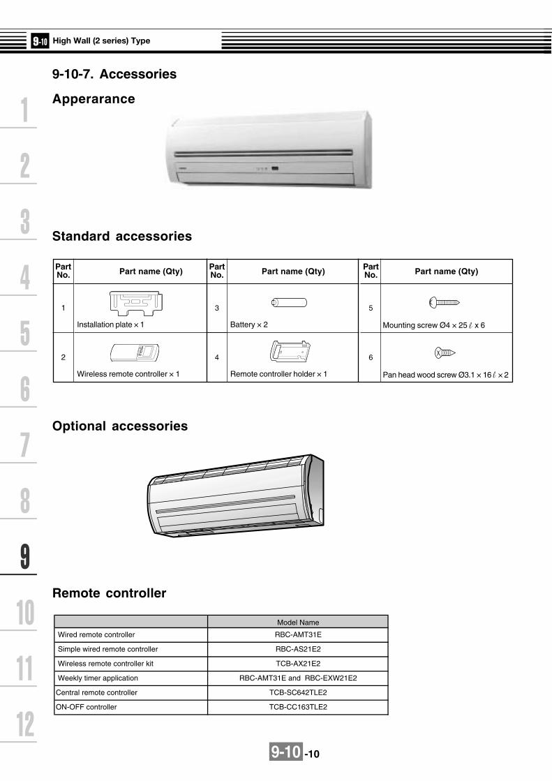
9-10 -10
9-10-7. Accessories
Apperarance
Standard accessories
Remote controller
Optional accessories
PartNo.
1
2
Part name (Qty)
Installation plate × 1
Wireless remote controller × 1
PartNo.
3
4
Part name (Qty)
Battery × 2
Remote controller holder × 1
PartNo.
5
6
Part name (Qty)
Mounting screw Ø4 × 25 x 6
Pan head wood screw Ø3.1 × 16 × 2
Central remote controller TCB-SC642TLE2
ON-OFF controller TCB-CC163TLE2
Weekly timer application
Model Name
RBC-AMT31E
RBC-AS21E2
TCB-AX21E2
RBC-AMT31E and RBC-EXW21E2
Wired remote controller
Simple wired remote controller
Wireless remote controller kit
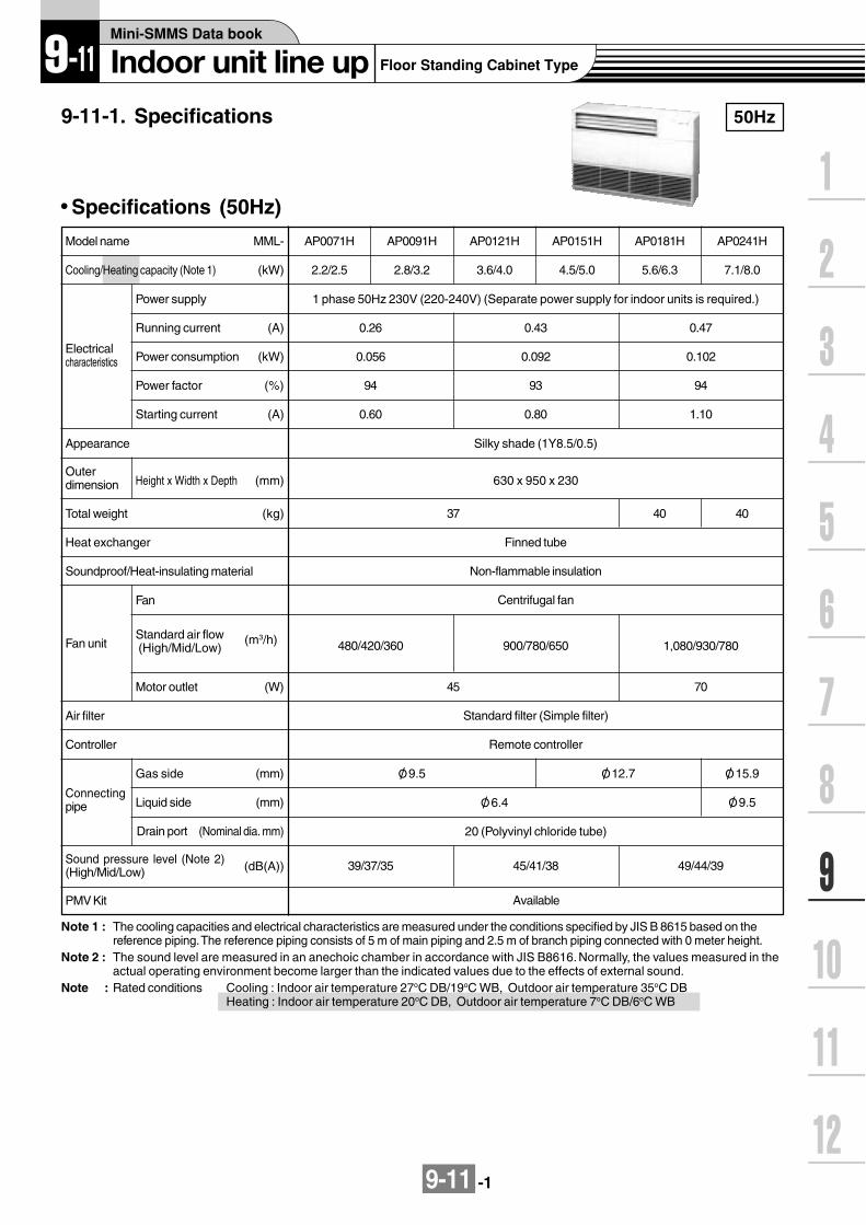
9-11 -1
9-11-1. Specifications 50Hz
Specifications (50Hz)
Note 1 : The cooling capacities and electrical characteristics are measured under the conditions specified by JIS B 8615 based on thereference piping. The reference piping consists of 5 m of main piping and 2.5 m of branch piping connected with 0 meter height.
Note 2 : The sound level are measured in an anechoic chamber in accordance with JIS B8616. Normally, the values measured in theactual operating environment become larger than the indicated values due to the effects of external sound.
Note : Rated conditions Cooling : Indoor air temperature 27oC DB/19oC WB, Outdoor air temperature 35oC DBHeating : Indoor air temperature 20oC DB, Outdoor air temperature 7oC DB/6oC WB
Cooling/Heating capacity (Note 1) (kW)
Electricalcharacteristics
Power supply
Running current (A)
Power consumption (kW)
Power factor (%)
Starting current (A)
Model name MML-
Appearance
Outerdimension Height x Width x Depth (mm)
Total weight (kg)
Heat exchanger
Soundproof/Heat-insulating material
Fan unit
Fan
Standard air flow (High/Mid/Low)
(m3/h)
Motor outlet (W)
Air filter
Controller
Gas side (mm)
Liquid side (mm)
Drain port (Nominal dia. mm)
Connectingpipe
Sound pressure level (Note 2)(High/Mid/Low) (dB(A))
AP0071H
2.2/2.5
1 phase 50Hz 230V (220-240V) (Separate power supply for indoor units is required.)
0.26
0.056
94
0.60
AP0091H
2.8/3.2
AP0121H
3.6/4.0
AP0151H
4.5/5.0
AP0181H
5.6/6.3
AP0241H
7.1/8.0
0.43
0.092
93
0.80
0.47
0.102
94
1.10
Silky shade (1Y8.5/0.5)
630 x 950 x 230
4037
Finned tube
Non-flammable insulation
Centrifugal fan
480/420/360 900/780/650
7045
Standard filter (Simple filter)
Remote controller
O/ 9.5 O/ 12.7
20 (Polyvinyl chloride tube)
49/44/3939/37/35 45/41/38
40
1,080/930/780
O/ 15.9
O/ 9.5O/ 6.4
PMV Kit Available

9-11 -2
60Hz
Specifications (60Hz)
Model name MML-
(kW)Cooling/Heating capacity (Note 1)
AP0071H
2.2/2.5
Power supply
Electricalcharacteristics
Running current (A)
Power consumption
Power factor
Starting current
Appearance
Outerdimension
Height x Width x Depth
Total weight
Heat exchanger
Soundproof/Heat-insulating material
Connectingpipe
Fan
Motor outlet
Fan unit
Air filter
Controller
Gas side
Liquid side
Drain port
Sound pressure level (Note 2)(High/Mid/Low)
(kW)
(%)
(A)
(mm)
(kg)
(m3/h)
(W)
(mm)
(mm)
(Nominal dia. mm)
(dB(A))
Standard air flow(High/Mid/Low)
AP0091H
2.8/3.2
AP0121H
3.6/4.0
AP0151H
4.5/5.0
AP0181H
5.6/6.3
AP0241H
7.1/8.0
1 phase 60Hz 220V (Separate power supply for indoor units is required.)
0.25 0.44 0.53
0.053 0.092 0.113
96 95 97
0.60 0.80 1.10
Silky shade (1Y8.5/0.5)
630 x 950 x 230
37 40
Finned tube
Non-flammable insulation
Centrifugal fan
480/420/360 900/780/650 1,080/930/780
45 70
Remote controller
Standard filter (Simple filter)
O/ 9.5 O/ 12.7 O/ 15.9
O/ 6.4 O/ 9.5
20 (Polyvinyl chloride tube)
39/37/35 45/41/38 49/44/39
Note 1 : The cooling capacities and electrical characteristics are measured under the conditions specified by JIS B 8615 based on thereference piping. The reference piping consists of 5 m of main piping and 2.5 m of branch piping connected with 0 meter height.
Note 2 : The sound levels are measured in an anechoic chamber in accordance with JIS B8616. Normally, the values measured inthe actual operating environment become larger than the indicated values due to the effects of external sound.
Note : Rated conditions Cooling : Indoor air temperature 27OC DB/19OC WB, Outdoor air temperature 35OC DBHeating : Indoor air temperature 20OC DB, Outdoor air temperature 7OC DB/6OC WB
PMV Kit Available
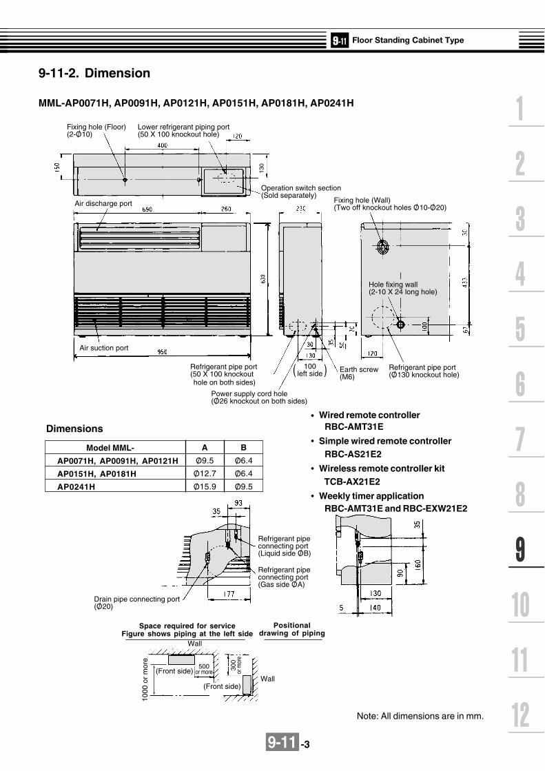
9-11 -3
9-11-2. Dimension
130
Fixing hole (Floor)(2-O/ 10)
Lower refrigerant piping port(50 X 100 knockout hole)
Operation switch section (Sold separately)
Fixing hole (Wall)(Two off knockout holes O/ 10-O/ 20)
Air suction port
100left side( )
Power supply cord hole(O/ 26 knockout on both sides)
Earth screw (M6)
Refrigerant pipe port(O/ 130 knockout hole)
Refrigerant pipe port(50 X 100 knockout
Hole fixing wall(2-10 X 24 long hole)
1000
or
mor
e
Drain pipe connecting port (O/ 20)
Refrigerant pipe connecting port(Liquid side O/ B)
Refrigerant pipe connecting port(Gas side O/ A)
Wall
Wall(Front side)
(Front side)
500or more 30
0or
mor
e
Air discharge port
hole on both sides)
MML-AP0071H, AP0091H, AP0121H, AP0151H, AP0181H, AP0241H
Space required for serviceFigure shows piping at the left side
Positionaldrawing of piping
Dimensions
Model MML-
AP0071H, AP0091H, AP0121H
AP0151H, AP0181H
AP0241H
A
O/ 9.5
O/ 12.7
O/ 15.9
B
O/ 6.4
O/ 6.4
O/ 9.5
Note: All dimensions are in mm.
Wired remote controller RBC-AMT31E
Simple wired remote controller RBC-AS21E2
Wireless remote controller kit TCB-AX21E2
Weekly timer application RBC-AMT31E and RBC-EXW21E2

9-11-4
9-11-3. Wirin
g d
iagram
Mo
del: M
ML
-AP
0071H, A
P0091H
, AP
0121H, A
P0151H
, AP
0181H, A
P0241H
5 3 177
99 5 3 1
RY007P301(BLK)
RY004
(GRY)CN304
(YEL)CN309
FUSET5.0A 250V~
RY006
RY005
H
RED BLK ORN BLU YEL
M L UL
3
1
3
1
3
1
3
1
3
1
3
1
RC
FM
CN104(YEL)
TA
21
21
CN102(RED)
TCJ
21
21
CN101(BLK)
CN100(BRN)
1
3
CN080(GRN)
TC2
PNL
EXCT
21
CN073(RED) 2
2
1
32
45
1
FILTERCN070(WHI)
CN081(BLK)
21
21
21
11
22
11
22
11
2
X Y
2
32
1 1
3
11 2
33 1 2 3 4 5 1 2 3 4 5 6 1 2 1 23 4 5 6 1 2 3 4 5 6
1 2 3 4 5 6
1 2 3 4 5 61 2 3 4 5 6
1 2 3 4 5 61 2 3 4 5 6
21
TC1
21
21
CN066(WHI)
CN067(BLK)
AC IN RED
WHI
CN040(BLU)
Outdoor unit Remote Controller
Power supplysingle phase
220-240V 50Hz220V 60Hz
Indoor unitearth screw
Closed-endconnector
Line Filter
RED
WHI
CN01(WHI)
CN03(RED)
CN02(BLU)
CN041(BLU)
CN050(WHI)
CN061(YEL)
T10
CN032(WHI)
FANDRIVE
OPTION
CN060(WHI)
BLU
BLU
BLK
BLK
RC
TR
U1
U1 U2
U2 A B
Network Adapter(Option)
MCC-1401
11
22
CN1
11
33CN074
(WHI)
CN075(WHI)
Power supplycircuit
TR
1 3CN068(BLU)
FANCN083(WHI)
RY002
DP1 3
CN033(GRN)
RY001
LM CN082(BLU)
PMV
11
2 33 CN030
(RED)
FS
1 2 3 4 5 61 2 3 4 5 6
1 234 561 234 56
PMV32
32
654
654
R(L) S(N)
CN01(WHI)
CN02(YEL)
Sub P.C. boardMCC-1520
Flow selector unit earth
screw
Colorindication
RED : REDWHI : WHITEYEL : YELLOWBLU : BLUEBLK : BLACKGRY : GRAYPNK : PINKORN :ORANGEBRN : BROWNGRN : GREEN
SymbolFM
RC
TR
TA
TC1,TC2,TCJ
RY001
RY002
RY004
RY005~007
PMV
Parts nameFan motor
Running capacitor
Transformer
Indoor temp sensor
Temp sensor
Louver control relay
Drain control relay
Heater control relay
Fan motor control relay
Pulse motor valve
Control P.C. boardfor Indoor unit
MCC-1403
1. indicates the terminal block.the letter inside indicates the terminal number.
2. A dotted line and broken line indicatethe wiring on site.
3. Indicates the control p.c. board.

9-11 -5
TC : Total Capacity (kW) SHC : Sensible Heat Capacity (kW)Indoor air temp.
Unit Outdoor 16.0˚CWB 18.0˚CWB 19.0˚CWB 20.0˚CWB 22.0˚CWB 24.0˚CWBsize air temp. 23˚CDB 26˚CDB 27˚CDB 28˚CDB 30˚CDB 32˚CDB
˚CDB TC SHC TC SHC TC SHC TC SHC TC SHC TC SHC10.0 2.0 1.3 2.1 1.4 2.2 1.4 2.3 1.4 2.4 1.4 2.5 1.412.0 2.0 1.3 2.1 1.4 2.2 1.4 2.3 1.4 2.4 1.4 2.5 1.414.0 2.0 1.3 2.1 1.4 2.2 1.4 2.3 1.4 2.4 1.4 2.5 1.416.0 2.0 1.3 2.1 1.4 2.2 1.4 2.3 1.4 2.4 1.4 2.5 1.418.0 2.0 1.3 2.1 1.4 2.2 1.4 2.3 1.4 2.4 1.4 2.5 1.420.0 2.0 1.3 2.1 1.4 2.2 1.4 2.3 1.4 2.4 1.4 2.5 1.421.0 2.0 1.3 2.1 1.4 2.2 1.4 2.3 1.4 2.4 1.4 2.5 1.4
007 23.0 2.0 1.3 2.1 1.4 2.2 1.4 2.3 1.4 2.4 1.4 2.5 1.425.0 2.0 1.3 2.1 1.4 2.2 1.4 2.3 1.4 2.4 1.4 2.5 1.427.0 2.0 1.3 2.1 1.4 2.2 1.4 2.3 1.4 2.4 1.4 2.5 1.429.0 2.0 1.3 2.1 1.4 2.2 1.4 2.3 1.4 2.4 1.4 2.5 1.431.0 2.0 1.3 2.1 1.4 2.2 1.4 2.3 1.4 2.4 1.4 2.5 1.433.0 2.0 1.3 2.1 1.4 2.2 1.4 2.3 1.4 2.4 1.4 2.5 1.435.0 2.0 1.3 2.1 1.4 2.2 1.4 2.3 1.4 2.4 1.4 2.5 1.437.0 2.0 1.3 2.1 1.4 2.2 1.4 2.2 1.4 2.4 1.4 2.5 1.339.0 1.9 1.2 2.0 1.3 2.1 1.3 2.2 1.3 2.3 1.3 2.4 1.310.0 2.5 1.5 2.7 1.6 2.8 1.6 2.9 1.6 3.1 1.6 3.2 1.512.0 2.5 1.5 2.7 1.6 2.8 1.6 2.9 1.6 3.1 1.6 3.2 1.514.0 2.5 1.5 2.7 1.6 2.8 1.6 2.9 1.6 3.1 1.6 3.2 1.516.0 2.5 1.5 2.7 1.6 2.8 1.6 2.9 1.6 3.1 1.6 3.2 1.518.0 2.5 1.5 2.7 1.6 2.8 1.6 2.9 1.6 3.1 1.6 3.2 1.520.0 2.5 1.5 2.7 1.6 2.8 1.6 2.9 1.6 3.1 1.6 3.2 1.521.0 2.5 1.5 2.7 1.6 2.8 1.6 2.9 1.6 3.1 1.6 3.2 1.5
009 23.0 2.5 1.5 2.7 1.6 2.8 1.6 2.9 1.6 3.1 1.6 3.2 1.525.0 2.5 1.5 2.7 1.6 2.8 1.6 2.9 1.6 3.1 1.6 3.2 1.527.0 2.5 1.5 2.7 1.6 2.8 1.6 2.9 1.6 3.1 1.6 3.2 1.529.0 2.5 1.5 2.7 1.6 2.8 1.6 2.9 1.6 3.1 1.6 3.2 1.531.0 2.5 1.5 2.7 1.6 2.8 1.6 2.9 1.6 3.1 1.6 3.2 1.533.0 2.5 1.5 2.7 1.6 2.8 1.6 2.9 1.6 3.1 1.6 3.2 1.535.0 2.5 1.5 2.7 1.6 2.8 1.6 2.9 1.6 3.1 1.6 3.2 1.537.0 2.5 1.5 2.7 1.6 2.7 1.6 2.8 1.6 3.0 1.6 3.1 1.539.0 2.4 1.4 2.6 1.5 2.7 1.5 2.8 1.5 2.9 1.5 3.1 1.510.0 3.2 2.0 3.4 2.1 3.5 2.1 3.6 2.1 3.8 2.1 4.0 2.012.0 3.2 2.0 3.4 2.1 3.5 2.1 3.6 2.1 3.8 2.1 4.0 2.014.0 3.2 2.0 3.4 2.1 3.5 2.1 3.6 2.1 3.8 2.1 4.0 2.016.0 3.2 2.0 3.4 2.1 3.5 2.1 3.6 2.1 3.8 2.1 4.0 2.018.0 3.2 2.0 3.4 2.1 3.5 2.1 3.6 2.1 3.8 2.1 4.0 2.020.0 3.2 2.0 3.4 2.1 3.5 2.1 3.6 2.1 3.8 2.1 4.0 2.021.0 3.2 2.0 3.4 2.1 3.5 2.1 3.6 2.1 3.8 2.1 4.0 2.0
012 23.0 3.2 2.0 3.4 2.1 3.5 2.1 3.6 2.1 3.8 2.1 4.0 2.025.0 3.2 2.0 3.4 2.1 3.5 2.1 3.6 2.1 3.8 2.1 4.0 2.027.0 3.2 2.0 3.4 2.1 3.5 2.1 3.6 2.1 3.8 2.1 4.0 2.029.0 3.2 2.0 3.4 2.1 3.5 2.1 3.6 2.1 3.8 2.1 4.0 2.031.0 3.2 2.0 3.4 2.1 3.5 2.1 3.6 2.1 3.8 2.1 4.0 2.033.0 3.2 2.0 3.4 2.1 3.5 2.1 3.6 2.1 3.8 2.1 4.0 2.035.0 3.2 2.0 3.4 2.1 3.5 2.1 3.6 2.1 3.8 2.1 4.0 2.037.0 3.1 1.9 3.3 2.1 3.4 2.1 3.5 2.1 3.7 2.0 3.9 2.039.0 3.1 1.9 3.3 2.0 3.4 2.0 3.5 2.0 3.7 2.0 3.8 1.9
9-11-4. Sensible capacity table(MML-AP***H)
Cooling capacity

9-11 -6
Cooling capacity (cont.)
Indoor air temp.Unit Outdoor 16.0˚CWB 18.0˚CWB 19.0˚CWB 20.0˚CWB 22.0˚CWB 24.0˚CWBsize air temp. 23˚CDB 26˚CDB 27˚CDB 28˚CDB 30˚CDB 32˚CDB
˚CDB TC SHC TC SHC TC SHC TC SHC TC SHC TC SHC10.0 4.1 2.6 4.4 2.8 4.5 2.8 4.6 2.8 4.9 2.8 5.1 2.712.0 4.1 2.6 4.4 2.8 4.5 2.8 4.6 2.8 4.9 2.8 5.1 2.714.0 4.1 2.6 4.4 2.8 4.5 2.8 4.6 2.8 4.9 2.8 5.1 2.716.0 4.1 2.6 4.4 2.8 4.5 2.8 4.6 2.8 4.9 2.8 5.1 2.718.0 4.1 2.6 4.4 2.8 4.5 2.8 4.6 2.8 4.9 2.8 5.1 2.720.0 4.1 2.6 4.4 2.8 4.5 2.8 4.6 2.8 4.9 2.8 5.1 2.721.0 4.1 2.6 4.4 2.8 4.5 2.8 4.6 2.8 4.9 2.8 5.1 2.7
015 23.0 4.1 2.6 4.4 2.8 4.5 2.8 4.6 2.8 4.9 2.8 5.1 2.725.0 4.1 2.6 4.4 2.8 4.5 2.8 4.6 2.8 4.9 2.8 5.1 2.727.0 4.1 2.6 4.4 2.8 4.5 2.8 4.6 2.8 4.9 2.8 5.1 2.729.0 4.1 2.6 4.4 2.8 4.5 2.8 4.6 2.8 4.9 2.8 5.1 2.731.0 4.1 2.6 4.4 2.8 4.5 2.8 4.6 2.8 4.9 2.8 5.1 2.733.0 4.1 2.6 4.4 2.8 4.5 2.8 4.6 2.8 4.9 2.8 5.1 2.735.0 4.1 2.6 4.4 2.8 4.5 2.8 4.6 2.8 4.9 2.8 5.1 2.737.0 4.0 2.6 4.3 2.8 4.4 2.7 4.5 2.7 4.8 2.7 5.0 2.739.0 3.9 2.5 4.2 2.6 4.3 2.6 4.4 2.6 4.7 2.6 4.9 2.510.0 5.1 3.3 5.4 3.5 5.6 3.5 5.8 3.5 6.1 3.5 6.4 3.412.0 5.1 3.3 5.4 3.5 5.6 3.5 5.8 3.5 6.1 3.5 6.4 3.414.0 5.1 3.3 5.4 3.5 5.6 3.5 5.8 3.5 6.1 3.5 6.4 3.416.0 5.1 3.3 5.4 3.5 5.6 3.5 5.8 3.5 6.1 3.5 6.4 3.418.0 5.1 3.3 5.4 3.5 5.6 3.5 5.8 3.5 6.1 3.5 6.4 3.420.0 5.1 3.3 5.4 3.5 5.6 3.5 5.8 3.5 6.1 3.5 6.4 3.421.0 5.1 3.3 5.4 3.5 5.6 3.5 5.8 3.5 6.1 3.5 6.4 3.4
018 23.0 5.1 3.3 5.4 3.5 5.6 3.5 5.8 3.5 6.1 3.5 6.4 3.425.0 5.1 3.3 5.4 3.5 5.6 3.5 5.8 3.5 6.1 3.5 6.4 3.427.0 5.1 3.3 5.4 3.5 5.6 3.5 5.8 3.5 6.1 3.5 6.4 3.429.0 5.1 3.3 5.4 3.5 5.6 3.5 5.8 3.5 6.1 3.5 6.4 3.431.0 5.1 3.3 5.4 3.5 5.6 3.5 5.8 3.5 6.1 3.5 6.4 3.433.0 5.1 3.3 5.4 3.5 5.6 3.5 5.8 3.5 6.1 3.5 6.4 3.435.0 5.1 3.3 5.4 3.5 5.6 3.5 5.8 3.5 6.1 3.5 6.4 3.437.0 5.0 3.2 5.3 3.4 5.5 3.4 5.7 3.4 6.0 3.4 6.3 3.339.0 4.9 3.1 5.2 3.3 5.4 3.3 5.5 3.3 5.9 3.3 6.1 3.210.0 6.4 4.2 6.9 4.5 7.1 4.5 7.3 4.5 7.7 4.5 8.1 4.412.0 6.4 4.2 6.9 4.5 7.1 4.5 7.3 4.5 7.7 4.5 8.1 4.414.0 6.4 4.2 6.9 4.5 7.1 4.5 7.3 4.5 7.7 4.5 8.1 4.416.0 6.4 4.2 6.9 4.5 7.1 4.5 7.3 4.5 7.7 4.5 8.1 4.418.0 6.4 4.2 6.9 4.5 7.1 4.5 7.3 4.5 7.7 4.5 8.1 4.420.0 6.4 4.2 6.9 4.5 7.1 4.5 7.3 4.5 7.7 4.5 8.1 4.421.0 6.4 4.2 6.9 4.5 7.1 4.5 7.3 4.5 7.7 4.5 8.1 4.4
024 23.0 6.4 4.2 6.9 4.5 7.1 4.5 7.3 4.5 7.7 4.5 8.1 4.425.0 6.4 4.2 6.9 4.5 7.1 4.5 7.3 4.5 7.7 4.5 8.1 4.427.0 6.4 4.2 6.9 4.5 7.1 4.5 7.3 4.5 7.7 4.5 8.1 4.429.0 6.4 4.2 6.9 4.5 7.1 4.5 7.3 4.5 7.7 4.5 8.1 4.431.0 6.4 4.2 6.9 4.5 7.1 4.5 7.3 4.5 7.7 4.5 8.1 4.433.0 6.4 4.2 6.9 4.5 7.1 4.5 7.3 4.5 7.7 4.5 8.1 4.435.0 6.4 4.2 6.9 4.5 7.1 4.5 7.3 4.5 7.7 4.5 8.1 4.437.0 6.3 4.2 6.7 4.4 7.0 4.4 7.2 4.4 7.6 4.4 7.9 4.339.0 6.2 4.0 6.6 4.2 6.8 4.2 7.0 4.2 7.4 4.2 7.8 4.1

9-11 -7
SHC : Sensible Heat Capacity (kW)
UnitOutdoor Indoor air temp. ˚CDB
size air temp. 16.0 18.0 20.0 22.0 24.0
˚CWB SHC SHC SHC SHC SHC-15.0 1.6 1.5 1.5 1.5 1.4-13.0 1.7 1.6 1.6 1.6 1.5-11.0 1.8 1.7 1.7 1.7 1.6-10.0 1.8 1.8 1.8 1.7 1.7-8.0 1.9 1.9 1.9 1.8 1.8-6.0 2.0 2.0 2.0 1.9 1.9-4.0 2.1 2.1 2.0 2.0 1.9
007 -2.0 2.2 2.2 2.1 2.1 2.00.0 2.3 2.3 2.2 2.2 2.12.0 2.4 2.4 2.3 2.3 2.24.0 2.5 2.5 2.4 2.4 2.36.0 2.6 2.6 2.5 2.4 2.48.0 2.6 2.6 2.5 2.4 2.4
10.0 2.6 2.6 2.5 2.4 2.412.0 2.6 2.6 2.5 2.4 2.414.0 2.6 2.6 2.5 2.4 2.4-15.0 2.0 2.0 1.9 1.9 1.8-13.0 2.1 2.1 2.1 2.0 1.9-11.0 2.3 2.2 2.2 2.1 2.1-10.0 2.3 2.3 2.2 2.2 2.1-8.0 2.5 2.4 2.4 2.3 2.3-6.0 2.6 2.6 2.5 2.4 2.4-4.0 2.7 2.7 2.6 2.6 2.5
009 -2.0 2.9 2.8 2.7 2.7 2.60.0 3.0 2.9 2.9 2.8 2.72.0 3.1 3.0 3.0 2.9 2.84.0 3.2 3.2 3.1 3.0 2.96.0 3.3 3.3 3.2 3.1 3.08.0 3.3 3.3 3.2 3.1 3.0
10.0 3.3 3.3 3.2 3.1 3.012.0 3.3 3.3 3.2 3.1 3.014.0 3.3 3.3 3.2 3.1 3.0-15.0 2.5 2.5 2.4 2.3 2.3-13.0 2.7 2.6 2.6 2.5 2.4-11.0 2.8 2.8 2.7 2.7 2.6-10.0 2.9 2.9 2.8 2.7 2.7-8.0 3.1 3.0 3.0 2.9 2.8-6.0 3.3 3.2 3.1 3.0 3.0-4.0 3.4 3.3 3.3 3.2 3.1
012 -2.0 3.6 3.5 3.4 3.3 3.30.0 3.7 3.7 3.6 3.5 3.42.0 3.9 3.8 3.7 3.6 3.54.0 4.0 3.9 3.9 3.8 3.76.0 4.2 4.1 4.0 3.9 3.88.0 4.2 4.1 4.0 3.9 3.8
10.0 4.2 4.1 4.0 3.9 3.812.0 4.2 4.1 4.0 3.9 3.814.0 4.2 4.1 4.0 3.9 3.8
Heating capacity

9-11 -8
Unit Outdoor Indoor air temp. ˚CDB
size air temp. 16.0 18.0 20.0 22.0 24.0
˚CWB SHC SHC SHC SHC SHC-15.0 3.1 3.1 3.0 2.9 2.9-13.0 3.3 3.3 3.2 3.1 3.0-11.0 3.6 3.5 3.4 3.3 3.2-10.0 3.7 3.6 3.5 3.4 3.3-8.0 3.9 3.8 3.7 3.6 3.5-6.0 4.1 4.0 3.9 3.8 3.7-4.0 4.3 4.2 4.1 4.0 3.9
015 -2.0 4.5 4.4 4.3 4.2 4.10.0 4.7 4.6 4.5 4.4 4.22.0 4.8 4.7 4.6 4.5 4.44.0 5.0 4.9 4.8 4.7 4.66.0 5.2 5.1 5.0 4.9 4.88.0 5.2 5.1 5.0 4.9 4.8
10.0 5.2 5.1 5.0 4.9 4.812.0 5.2 5.1 5.0 4.9 4.814.0 5.2 5.1 5.0 4.9 4.8-15.0 3.9 3.9 3.8 3.7 3.6-13.0 4.2 4.1 4.0 3.9 3.8-11.0 4.5 4.4 4.3 4.2 4.1-10.0 4.6 4.5 4.4 4.3 4.2-8.0 4.9 4.8 4.7 4.6 4.4-6.0 5.1 5.0 4.9 4.8 4.7-4.0 5.4 5.3 5.2 5.0 4.9
018 -2.0 5.6 5.5 5.4 5.3 5.10.0 5.9 5.8 5.6 5.5 5.32.0 6.1 6.0 5.9 5.7 5.64.0 6.3 6.2 6.1 5.9 5.86.0 6.6 6.4 6.3 6.1 6.08.0 6.6 6.4 6.3 6.1 6.0
10.0 6.6 6.4 6.3 6.1 6.012.0 6.6 6.4 6.3 6.1 6.014.0 6.6 6.4 6.3 6.1 6.0-15.0 5.0 4.9 4.8 4.7 4.6-13.0 5.3 5.2 5.1 5.0 4.9-11.0 5.7 5.6 5.5 5.3 5.2-10.0 5.8 5.7 5.6 5.5 5.3-8.0 6.2 6.1 5.9 5.8 5.6-6.0 6.5 6.4 6.2 6.1 5.9-4.0 6.8 6.7 6.6 6.4 6.2
024 -2.0 7.1 7.0 6.9 6.7 6.50.0 7.4 7.3 7.1 7.0 6.82.0 7.7 7.6 7.4 7.3 7.14.0 8.0 7.9 7.7 7.5 7.36.0 8.3 8.2 8.0 7.8 7.68.0 8.3 8.2 8.0 7.8 7.6
10.0 8.3 8.2 8.0 7.8 7.612.0 8.3 8.2 8.0 7.8 7.614.0 8.3 8.2 8.0 7.8 7.6
Heating capacity (cont.)
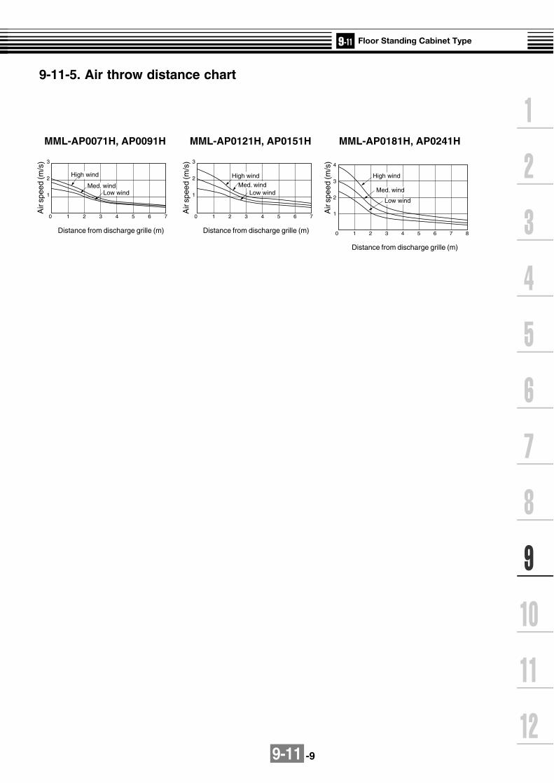
9-11 -9
0 1 2 3 4 5 6 7
1
2
3
0 1 2 3 4 5 6 7
1
2
3
0 1 2 3 4 5 6 7 8
1
2
3
4
High wind
Med. wind
Low wind
High wind
Med. windLow wind
High wind
Med. windLow wind
9-11-5. Air throw distance chart
MML-AP0071H, AP0091H MML-AP0121H, AP0151H MML-AP0181H, AP0241H
Air
spee
d (m
/s)
Distance from discharge grille (m)
Air
spee
d (m
/s)
Distance from discharge grille (m)
Air
spee
d (m
/s)
Distance from discharge grille (m)

9-11 -10
9-11-6. Sound characteristics (NC-Curve)
[Measuring location]
MML-AP0071H,MML-AP0091H MML-AP0121H,MML-AP0151H
Fan tap H M L Fan tap H M LSound pressure Sound pressure
level (dB(A)) level (dB(A))
MML-AP0181H,MML-AP0241H
Fan tap H M LSound pressure
level (dB(A))
41 3839 37
49 44 39
35 45
1 0
2 0
3 0
4 0
5 0
6 0
7 0
8 0
9 0
6 3 1 2 5 2 5 0 5 0 0 1 0 0 0 2 0 0 0 4 0 0 0 8 0 0 0
O c
t a v e
b a n
d s
o u n
d p r
e s s
u r e
l e v e
l ( d
B )
N C - 6 0
N C - 5 0
N C - 4 0
N C - 3 0
N C - 2 0
LL
HH MM
N C - 7 0
1 0
2 0
3 0
4 0
5 0
6 0
7 0
8 0
9 0
6 3 1 2 5 2 5 0 5 0 0 1 0 0 0 2 0 0 0 4 0 0 0 8 0 0 0
O c
t a v e
b a n
d s
o u n
d p r
e s s
u r e
l e v e
l ( d
B )
N C - 6 0
N C - 5 0
N C - 4 0
N C - 3 0
N C - 2 0
LL
HH
MM
N C - 7 0
1 0
2 0
3 0
4 0
5 0
6 0
7 0
8 0
9 0
6 3 1 2 5 2 5 0 5 0 0 1 0 0 0 2 0 0 0 4 0 0 0 8 0 0 0
O c
t a v e
b a n
d s
o u n
d p r
e s s
u r e
l e v e
l ( d
B )
N C - 6 0
N C - 5 0
N C - 4 0
N C - 3 0
N C - 2 0
N C - 7 0
LL
HH MM
1m
1mAir outlet
Microphon
Approximate threshold ofhearing for continuous noise
Octave band center frequency (Hz)
Octave band center frequency (Hz)
Octave band center frequency (Hz)
Approximate threshold ofhearing for continuous noise
Approximate threshold ofhearing for continuous noise
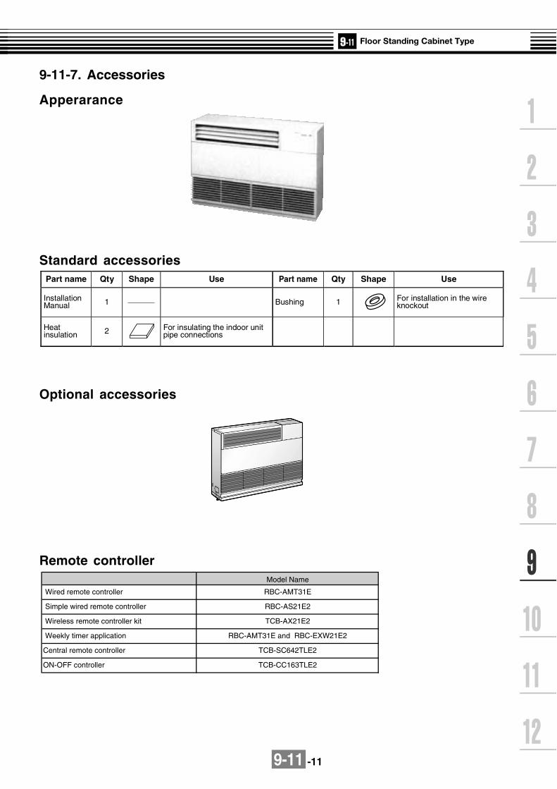
9-11 -11
9-11-7. Accessories
Apperarance
Standard accessories
Remote controller
Optional accessories
Part name Qty Shape Use Part name Qty Shape Use
Installation Manual 1 Bushing 1 For installation in the wire
knockout
Heat insulation 2 For insulating the indoor unit
pipe connections
Central remote controller TCB-SC642TLE2
ON-OFF controller TCB-CC163TLE2
Weekly timer application
Model Name
RBC-AMT31E
RBC-AS21E2
TCB-AX21E2
RBC-AMT31E and RBC-EXW21E2
Wired remote controller
Simple wired remote controller
Wireless remote controller kit
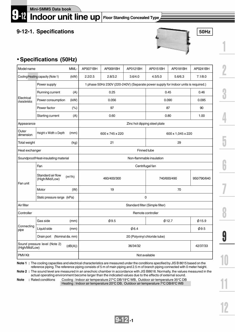
9-12 -1
9-12-1. Specifications 50Hz
Specifications (50Hz)
Note 1 : The cooling capacities and electrical characteristics are measured under the conditions specified by JIS B 8615 based on thereference piping. The reference piping consists of 5 m of main piping and 2.5 m of branch piping connected with 0 meter height.
Note 2 : The sound level are measured in an anechoic chamber in accordance with JIS B8616. Normally, the values measured in theactual operating environment become larger than the indicated values due to the effects of external sound.
Note : Rated conditions Cooling : Indoor air temperature 27oC DB/19oC WB, Outdoor air temperature 35oC DBHeating : Indoor air temperature 20oC DB, Outdoor air temperature 7oC DB/6oC WB
Cooling/Heating capacity (Note 1) (kW)
Electricalcharacteristics
Power supply
Running current (A)
Power consumption (kW)
Power factor (%)
Starting current (A)
Model name MML-
Appearance
Outerdimension Height x Width x Depth (mm)
Total weight (kg)
Heat exchanger
Soundproof/Heat-insulating material
Fan unit
Fan
Standard air flow(High/Mid/Low)
(m3/h)
Motor (W)
Static pressure range (kPa)
Air filter
Controller
Gas side (mm)
Liquid side (mm)
Drain port (Nominal dia. mm)
Connectingpipe
Sound pressure level (Note 2)(High/Mid/Low) (dB(A))
AP0071BH
2.2/2.5
1 phase 50Hz 230V (220-240V) (Separate power supply for indoor units is required.)
0.25
0.056
97
0.60
AP0091BH
2.8/3.2
AP0121BH
3.6/4.0
AP0151BH
4.5/5.0
AP0181BH
5.6/6.3
AP0241BH
7.1/8.0
0.45
0.090
87
0.80
Zinc hot dipping steel plate
600 x 745 x 220
21
Finned tube
Non-flammable insulation
Centrifugal fan
460/400/300 740/600/490
19
O/ 9.5 O/ 12.7
20 (Polyvinyl chloride tube)
42/37/3336/34/32
O/ 15.9
O/ 9.5O/ 6.4
0.46
0.095
90
1.00
600 x 1,045 x 220
29
950/790/640
70
0
Standard filter (Simple filter)
Remote controller
PMV Kit Not available

9-12 -2
60Hz
Specifications (60Hz)
Model name MML-
(kW)Cooling/Heating capacity (Note 1)
AP0071BH
2.2/2.5
Power supply
Electricalcharacteristics
Running current (A)
(kW)Power consumption
Power factor
Starting current
Appearance
Outerdimension
Height x Width xDepth
Total weight
Heat exchanger
Soundproof/Heat-insulating material
Fan
Standard air flow(High/Mid/Low)
Motor
Static pressure range
Fan unit
Air filter
Controller
Gas side
Liquid side
Drain port
Connectingpipe
Sound pressure level (Note 2) (High/Mid/Low)
(%)
(A)
(mm)
(kg)
(m3/h)
(W)
(kPa)
(mm)
(Nominal dia. mm)
(dB(A))
AP0091BH
2.8/3.2
AP0121BH
3.6/4.0
AP0151BH
4.5/5.0
AP0181BH
5.6/6.3
AP0241BH
7.1/8.0
1 phase 60Hz 220V (Separate power supply for indoor units is required.)
0.27 0.46 0.51
0.058 0.096 0.110
98 95 98
0.60 0.80 1.00
600 x 745 x 220 600 x 1,045 x 220
460/400/300 740/600/490
Zinc hot dipping steel plate
Finned tube
Non-flammable insulation
Centrifugal fan
950/790/640
19 70
0
Standard filter (Simple filter)
O/ 9.5 O/ 12.7 O/ 15.9
O/ 6.4 O/ 9.5
20 (Polyvinyl chloride tube)
36/34/32 42/37/33
(mm)
21 29
Remote controller
Note 1 : The cooling capacities and electrical characteristics are measured under the conditions specified by JIS B 8615 based on thereference piping. The reference piping consists of 5 m of main piping and 2.5 m of branch piping connected with 0 meter height.
Note 2 : The sound levels are measured in an anechoic chamber in accordance with JIS B8616. Normally, the values measured inthe actual operating environment become larger than the indicated values due to the effects of external sound.
Note : Rated conditions Cooling : Indoor air temperature 27OC DB/19OC WB, Outdoor air temperature 35OC DBHeating : Indoor air temperature 20OC DB, Outdoor air temperature 7OC DB/6OC WB
PMV Kit Not available
(Revised 07 Apr 2006)

9-12 -3
(Service space)
150or more
(Service space)
150or more
Fixing hole (Floor) (Discharge port size in flange)
Ceiling board section
(Air discharge port size in flange)
G-O/ 4.7 hole(Front side and rear side each)
4-O/ 15 hole(For mounting rear side)
Expansionvalve box
2-O/ 4.7 hole (Left/right side each)
2-12 5 18 holeFixing hole (Floor)
16
4 2.7
120
120
9-12-2. Dimension
MML-AP0071BH, AP0091BH, AP0121BH, AP0151BH, AP0181BH, AP0241BH
Dimensions
Name
Pipe connecting port at liquid side (O/ E)
Pipe connecting port at gas side (O/ F)
Drain pipe connecting port (20A)
Electric parts box(Earth terminal on the inside)
Air filter
No.
1
2
3
4
5
Model MML-
AP0071BH, AP0091BH, AP0121BH
AP0151BH, AP0181BH
AP0241BH
A
610
910
B
580
880
C
550
850
D
4
7
E
6.4
9.5
F
9.5
12.7
15.9
G
5
8
Wired remote controller RBC-AMT31E
Simple wired remote controller RBC-AS21E2
Wireless remote controller kit TCB-AX21E2
Weekly timer application RBC-AMT31E and RBC-EXW21E2
Note: All dimensions are in mm.

9-12-4
9-12-3. Wirin
g d
iagram
Mo
del: M
ML
-AP
0071BH
, AP
0091BH
, AP
0121BH
, AP
0151BH
, AP
0181BH
, AP
0241BH
GRN
5 3 177
99 5 3 1
RY007R301(BLK)
RY004
(GRY)CN304
(YEL)CN309
(BLK)CN067
FUSET5.0A 250V~
RY006
RY005
H
RED BLK ORN BLU YEL
M L UL
3
1
3
1
3
1
3
1
3
1
RCWH
I
1
3
1
3
CN104(YEL)
TA
21
21
CN102(RED)
TCJ
21
21
CN101(BLK)
CN100(BRW)
1
3
CN080(GRN)
TC2
PNL
EXCT
21
CN073(RED) 2
2
1
FILTERCN070(WHI)
CN081(BLK)
21
21
11
22
11
22
11
22
2 23
21 1
1 13
11 2
33 1 2 3 4 5 1 2 3 4 5 6 1 2 1 23 4 5 6 1 2 3 4 5 6
1 2 3 4 5 6
1 2 3 4 5 61 2 3 4 5 6
1 2 3 4 5 61 2 3 4 5 6
21
43
5
2
2
1
TC1
AC IN
CN044(BRW)
21 CN066
(WHI)
CN040(BLU)
Outdoor unit
Remote ControllerPower supplysingle phase
220-240V 50Hz220V 60Hz
Indoor unitearth screw
Closed-endconnector
CN01(WHI)
CN03(RED)
CN02(BLU)
CN03(RED)
CN041(BLU)
CN050(WHI)
CN061(YEL)
CN032(WHI)
FANDRIVE
OPTION
CN060(WHI)
EMG
TR
RED
RE
D
WH
I
WHI
U1 U2
U1 U2
A B X Y
Networkadapter(Option)
MCC-1401
For AP0071BH,AP0091BH,AP0121BH
11
22
CN1
11
33CN074
(WHI)
CN075(WHI)
Power supplycircuit
TR
11
33CN068
(BLU)
FANCN083(WHI)
RY002
11
33
11
2 33CN033
(GRN)
RY001
CN082(BLU)
CN030(RED)
PMV1 2 3 4 5 61 2 3 4 5 6
1 234 561 234 56
PMV
RED
42
42
365
365
R(L) S(N)
FMGRN
5 3 177
99 5 3 1
RED BLK ORN BLU YELFANCN083(WHI)
REDWHI
231
231
654
654
RC
FM
CN01(WHI)
CN02(YEL)
Sub P.C. boardMCC-1520
Flow selector unit earth
screw
SymbolFM
RC
TR
TA
TC1,TC2,TCJ
RY001
RY002
RY004
RY005~007
PMV
Parts nameFan motor
Running capacitor
Transformer
Indoor temp sensor
Temp sensor
Louver control relay
Drain control relay
Heater control relay
Fan motor control relay
Pulse motor valve
Colorindication
RED : REDWHI : WHITEYEL : YELLOWBLU : BLUEBLK : BLACKGRY : GRAYPNK : PINKORN :ORANGEBRN : BROWNGRN : GREEN
Control P.C. boardfor undoor unit
MCC-1403
1. indicates the terminal block.the letter inside indicates the terminal number.
2. A dotted line and broken line indicatethe wiring on site.
3. Indicates the control p.c. board.

9-12 -5
TC : Total Capacity (kW) SHC : Sensible Heat Capacity (kW)Indoor air temp.
Unit Outdoor 16.0˚CWB 18.0˚CWB 19.0˚CWB 20.0˚CWB 22.0˚CWB 24.0˚CWBsize air temp. 23˚CDB 26˚CDB 27˚CDB 28˚CDB 30˚CDB 32˚CDB
˚CDB TC SHC TC SHC TC SHC TC SHC TC SHC TC SHC10.0 2.0 1.3 2.1 1.4 2.2 1.4 2.3 1.4 2.4 1.4 2.5 1.412.0 2.0 1.3 2.1 1.4 2.2 1.4 2.3 1.4 2.4 1.4 2.5 1.414.0 2.0 1.3 2.1 1.4 2.2 1.4 2.3 1.4 2.4 1.4 2.5 1.416.0 2.0 1.3 2.1 1.4 2.2 1.4 2.3 1.4 2.4 1.4 2.5 1.418.0 2.0 1.3 2.1 1.4 2.2 1.4 2.3 1.4 2.4 1.4 2.5 1.420.0 2.0 1.3 2.1 1.4 2.2 1.4 2.3 1.4 2.4 1.4 2.5 1.421.0 2.0 1.3 2.1 1.4 2.2 1.4 2.3 1.4 2.4 1.4 2.5 1.4
007 23.0 2.0 1.3 2.1 1.4 2.2 1.4 2.3 1.4 2.4 1.4 2.5 1.425.0 2.0 1.3 2.1 1.4 2.2 1.4 2.3 1.4 2.4 1.4 2.5 1.427.0 2.0 1.3 2.1 1.4 2.2 1.4 2.3 1.4 2.4 1.4 2.5 1.429.0 2.0 1.3 2.1 1.4 2.2 1.4 2.3 1.4 2.4 1.4 2.5 1.431.0 2.0 1.3 2.1 1.4 2.2 1.4 2.3 1.4 2.4 1.4 2.5 1.433.0 2.0 1.3 2.1 1.4 2.2 1.4 2.3 1.4 2.4 1.4 2.5 1.435.0 2.0 1.3 2.1 1.4 2.2 1.4 2.3 1.4 2.4 1.4 2.5 1.437.0 2.0 1.3 2.1 1.4 2.2 1.4 2.2 1.4 2.4 1.4 2.5 1.339.0 1.9 1.2 2.0 1.3 2.1 1.3 2.2 1.3 2.3 1.3 2.4 1.310.0 2.5 1.5 2.7 1.6 2.8 1.6 2.9 1.6 3.1 1.6 3.2 1.512.0 2.5 1.5 2.7 1.6 2.8 1.6 2.9 1.6 3.1 1.6 3.2 1.514.0 2.5 1.5 2.7 1.6 2.8 1.6 2.9 1.6 3.1 1.6 3.2 1.516.0 2.5 1.5 2.7 1.6 2.8 1.6 2.9 1.6 3.1 1.6 3.2 1.518.0 2.5 1.5 2.7 1.6 2.8 1.6 2.9 1.6 3.1 1.6 3.2 1.520.0 2.5 1.5 2.7 1.6 2.8 1.6 2.9 1.6 3.1 1.6 3.2 1.521.0 2.5 1.5 2.7 1.6 2.8 1.6 2.9 1.6 3.1 1.6 3.2 1.5
009 23.0 2.5 1.5 2.7 1.6 2.8 1.6 2.9 1.6 3.1 1.6 3.2 1.525.0 2.5 1.5 2.7 1.6 2.8 1.6 2.9 1.6 3.1 1.6 3.2 1.527.0 2.5 1.5 2.7 1.6 2.8 1.6 2.9 1.6 3.1 1.6 3.2 1.529.0 2.5 1.5 2.7 1.6 2.8 1.6 2.9 1.6 3.1 1.6 3.2 1.531.0 2.5 1.5 2.7 1.6 2.8 1.6 2.9 1.6 3.1 1.6 3.2 1.533.0 2.5 1.5 2.7 1.6 2.8 1.6 2.9 1.6 3.1 1.6 3.2 1.535.0 2.5 1.5 2.7 1.6 2.8 1.6 2.9 1.6 3.1 1.6 3.2 1.537.0 2.5 1.5 2.7 1.6 2.7 1.6 2.8 1.6 3.0 1.6 3.1 1.539.0 2.4 1.4 2.6 1.5 2.7 1.5 2.8 1.5 2.9 1.5 3.1 1.510.0 3.3 2.1 3.5 2.2 3.6 2.2 3.7 2.2 3.9 2.2 4.1 2.112.0 3.3 2.1 3.5 2.2 3.6 2.2 3.7 2.2 3.9 2.2 4.1 2.114.0 3.3 2.1 3.5 2.2 3.6 2.2 3.7 2.2 3.9 2.2 4.1 2.116.0 3.3 2.1 3.5 2.2 3.6 2.2 3.7 2.2 3.9 2.2 4.1 2.118.0 3.3 2.1 3.5 2.2 3.6 2.2 3.7 2.2 3.9 2.2 4.1 2.120.0 3.3 2.1 3.5 2.2 3.6 2.2 3.7 2.2 3.9 2.2 4.1 2.121.0 3.3 2.1 3.5 2.2 3.6 2.2 3.7 2.2 3.9 2.2 4.1 2.1
012 23.0 3.3 2.1 3.5 2.2 3.6 2.2 3.7 2.2 3.9 2.2 4.1 2.125.0 3.3 2.1 3.5 2.2 3.6 2.2 3.7 2.2 3.9 2.2 4.1 2.127.0 3.3 2.1 3.5 2.2 3.6 2.2 3.7 2.2 3.9 2.2 4.1 2.129.0 3.3 2.1 3.5 2.2 3.6 2.2 3.7 2.2 3.9 2.2 4.1 2.131.0 3.3 2.1 3.5 2.2 3.6 2.2 3.7 2.2 3.9 2.2 4.1 2.133.0 3.3 2.1 3.5 2.2 3.6 2.2 3.7 2.2 3.9 2.2 4.1 2.135.0 3.3 2.1 3.5 2.2 3.6 2.2 3.7 2.2 3.9 2.2 4.1 2.137.0 3.2 2.0 3.4 2.2 3.5 2.2 3.6 2.2 3.8 2.1 4.0 2.139.0 3.1 2.0 3.4 2.1 3.5 2.1 3.6 2.1 3.8 2.1 3.9 2.0
9-12-4. Sensible capacity table(MML-AP***BH)
Cooling capacity

9-12 -6
Cooling capacity (cont.)Indoor air temp.
Unit Outdoor 16.0˚CWB 18.0˚CWB 19.0˚CWB 20.0˚CWB 22.0˚CWB 24.0˚CWBsize air temp. 23˚CDB 26˚CDB 27˚CDB 28˚CDB 30˚CDB 32˚CDB
˚CDB TC SHC TC SHC TC SHC TC SHC TC SHC TC SHC10.0 4.1 2.6 4.4 2.8 4.5 2.8 4.6 2.8 4.9 2.8 5.1 2.712.0 4.1 2.6 4.4 2.8 4.5 2.8 4.6 2.8 4.9 2.8 5.1 2.714.0 4.1 2.6 4.4 2.8 4.5 2.8 4.6 2.8 4.9 2.8 5.1 2.716.0 4.1 2.6 4.4 2.8 4.5 2.8 4.6 2.8 4.9 2.8 5.1 2.718.0 4.1 2.6 4.4 2.8 4.5 2.8 4.6 2.8 4.9 2.8 5.1 2.720.0 4.1 2.6 4.4 2.8 4.5 2.8 4.6 2.8 4.9 2.8 5.1 2.721.0 4.1 2.6 4.4 2.8 4.5 2.8 4.6 2.8 4.9 2.8 5.1 2.7
015 23.0 4.1 2.6 4.4 2.8 4.5 2.8 4.6 2.8 4.9 2.8 5.1 2.725.0 4.1 2.6 4.4 2.8 4.5 2.8 4.6 2.8 4.9 2.8 5.1 2.727.0 4.1 2.6 4.4 2.8 4.5 2.8 4.6 2.8 4.9 2.8 5.1 2.729.0 4.1 2.6 4.4 2.8 4.5 2.8 4.6 2.8 4.9 2.8 5.1 2.731.0 4.1 2.6 4.4 2.8 4.5 2.8 4.6 2.8 4.9 2.8 5.1 2.733.0 4.1 2.6 4.4 2.8 4.5 2.8 4.6 2.8 4.9 2.8 5.1 2.735.0 4.1 2.6 4.4 2.8 4.5 2.8 4.6 2.8 4.9 2.8 5.1 2.737.0 4.0 2.6 4.3 2.8 4.4 2.7 4.5 2.7 4.8 2.7 5.0 2.739.0 3.9 2.5 4.2 2.6 4.3 2.6 4.4 2.6 4.7 2.6 4.9 2.510.0 5.1 3.3 5.4 3.5 5.6 3.5 5.8 3.5 6.1 3.5 6.4 3.412.0 5.1 3.3 5.4 3.5 5.6 3.5 5.8 3.5 6.1 3.5 6.4 3.414.0 5.1 3.3 5.4 3.5 5.6 3.5 5.8 3.5 6.1 3.5 6.4 3.416.0 5.1 3.3 5.4 3.5 5.6 3.5 5.8 3.5 6.1 3.5 6.4 3.418.0 5.1 3.3 5.4 3.5 5.6 3.5 5.8 3.5 6.1 3.5 6.4 3.420.0 5.1 3.3 5.4 3.5 5.6 3.5 5.8 3.5 6.1 3.5 6.4 3.421.0 5.1 3.3 5.4 3.5 5.6 3.5 5.8 3.5 6.1 3.5 6.4 3.4
018 23.0 5.1 3.3 5.4 3.5 5.6 3.5 5.8 3.5 6.1 3.5 6.4 3.425.0 5.1 3.3 5.4 3.5 5.6 3.5 5.8 3.5 6.1 3.5 6.4 3.427.0 5.1 3.3 5.4 3.5 5.6 3.5 5.8 3.5 6.1 3.5 6.4 3.429.0 5.1 3.3 5.4 3.5 5.6 3.5 5.8 3.5 6.1 3.5 6.4 3.431.0 5.1 3.3 5.4 3.5 5.6 3.5 5.8 3.5 6.1 3.5 6.4 3.433.0 5.1 3.3 5.4 3.5 5.6 3.5 5.8 3.5 6.1 3.5 6.4 3.435.0 5.1 3.3 5.4 3.5 5.6 3.5 5.8 3.5 6.1 3.5 6.4 3.437.0 5.0 3.2 5.3 3.4 5.5 3.4 5.7 3.4 6.0 3.4 6.3 3.339.0 4.9 3.1 5.2 3.3 5.4 3.3 5.5 3.3 5.9 3.3 6.1 3.210.0 6.4 4.2 6.9 4.5 7.1 4.5 7.3 4.5 7.7 4.5 8.1 4.412.0 6.4 4.2 6.9 4.5 7.1 4.5 7.3 4.5 7.7 4.5 8.1 4.414.0 6.4 4.2 6.9 4.5 7.1 4.5 7.3 4.5 7.7 4.5 8.1 4.416.0 6.4 4.2 6.9 4.5 7.1 4.5 7.3 4.5 7.7 4.5 8.1 4.418.0 6.4 4.2 6.9 4.5 7.1 4.5 7.3 4.5 7.7 4.5 8.1 4.420.0 6.4 4.2 6.9 4.5 7.1 4.5 7.3 4.5 7.7 4.5 8.1 4.421.0 6.4 4.2 6.9 4.5 7.1 4.5 7.3 4.5 7.7 4.5 8.1 4.4
024 23.0 6.4 4.2 6.9 4.5 7.1 4.5 7.3 4.5 7.7 4.5 8.1 4.425.0 6.4 4.2 6.9 4.5 7.1 4.5 7.3 4.5 7.7 4.5 8.1 4.427.0 6.4 4.2 6.9 4.5 7.1 4.5 7.3 4.5 7.7 4.5 8.1 4.429.0 6.4 4.2 6.9 4.5 7.1 4.5 7.3 4.5 7.7 4.5 8.1 4.431.0 6.4 4.2 6.9 4.5 7.1 4.5 7.3 4.5 7.7 4.5 8.1 4.433.0 6.4 4.2 6.9 4.5 7.1 4.5 7.3 4.5 7.7 4.5 8.1 4.435.0 6.4 4.2 6.9 4.5 7.1 4.5 7.3 4.5 7.7 4.5 8.1 4.437.0 6.3 4.2 6.7 4.4 7.0 4.4 7.2 4.4 7.6 4.4 7.9 4.339.0 6.2 4.0 6.6 4.2 6.8 4.2 7.0 4.2 7.4 4.2 7.8 4.1
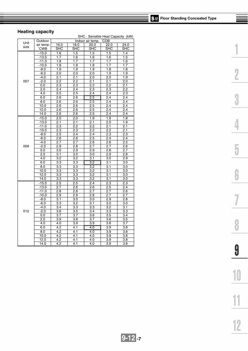
9-12 -7
SHC : Sensible Heat Capacity (kW)
Unit Outdoor Indoor air temp. ˚CDB
size air temp. 16.0 18.0 20.0 22.0 24.0
˚CWB SHC SHC SHC SHC SHC-15.0 1.6 1.5 1.5 1.5 1.4-13.0 1.7 1.6 1.6 1.6 1.5-11.0 1.8 1.7 1.7 1.7 1.6-10.0 1.8 1.8 1.8 1.7 1.7-8.0 1.9 1.9 1.9 1.8 1.8-6.0 2.0 2.0 2.0 1.9 1.9-4.0 2.1 2.1 2.0 2.0 1.9
007 -2.0 2.2 2.2 2.1 2.1 2.00.0 2.3 2.3 2.2 2.2 2.12.0 2.4 2.4 2.3 2.3 2.24.0 2.5 2.5 2.4 2.4 2.36.0 2.6 2.6 2.5 2.4 2.48.0 2.6 2.6 2.5 2.4 2.4
10.0 2.6 2.6 2.5 2.4 2.412.0 2.6 2.6 2.5 2.4 2.414.0 2.6 2.6 2.5 2.4 2.4-15.0 2.0 2.0 1.9 1.9 1.8-13.0 2.1 2.1 2.1 2.0 1.9-11.0 2.3 2.2 2.2 2.1 2.1-10.0 2.3 2.3 2.2 2.2 2.1-8.0 2.5 2.4 2.4 2.3 2.3-6.0 2.6 2.6 2.5 2.4 2.4-4.0 2.7 2.7 2.6 2.6 2.5
009 -2.0 2.9 2.8 2.7 2.7 2.60.0 3.0 2.9 2.9 2.8 2.72.0 3.1 3.0 3.0 2.9 2.84.0 3.2 3.2 3.1 3.0 2.96.0 3.3 3.3 3.2 3.1 3.08.0 3.3 3.3 3.2 3.1 3.0
10.0 3.3 3.3 3.2 3.1 3.012.0 3.3 3.3 3.2 3.1 3.014.0 3.3 3.3 3.2 3.1 3.0-15.0 2.5 2.5 2.4 2.3 2.3-13.0 2.7 2.6 2.6 2.5 2.4-11.0 2.8 2.8 2.7 2.7 2.6-10.0 2.9 2.9 2.8 2.7 2.7-8.0 3.1 3.0 3.0 2.9 2.8-6.0 3.3 3.2 3.1 3.0 3.0-4.0 3.4 3.3 3.3 3.2 3.1
012 -2.0 3.6 3.5 3.4 3.3 3.30.0 3.7 3.7 3.6 3.5 3.42.0 3.9 3.8 3.7 3.6 3.54.0 4.0 3.9 3.9 3.8 3.76.0 4.2 4.1 4.0 3.9 3.88.0 4.2 4.1 4.0 3.9 3.8
10.0 4.2 4.1 4.0 3.9 3.812.0 4.2 4.1 4.0 3.9 3.814.0 4.2 4.1 4.0 3.9 3.8
Heating capacity

9-12 -8
UnitOutdoor Indoor air temp. ˚CDB
size air temp. 16.0 18.0 20.0 22.0 24.0
˚CWB SHC SHC SHC SHC SHC-15.0 3.1 3.1 3.0 2.9 2.9-13.0 3.3 3.3 3.2 3.1 3.0-11.0 3.6 3.5 3.4 3.3 3.2-10.0 3.7 3.6 3.5 3.4 3.3-8.0 3.9 3.8 3.7 3.6 3.5-6.0 4.1 4.0 3.9 3.8 3.7-4.0 4.3 4.2 4.1 4.0 3.9
015 -2.0 4.5 4.4 4.3 4.2 4.10.0 4.7 4.6 4.5 4.4 4.22.0 4.8 4.7 4.6 4.5 4.44.0 5.0 4.9 4.8 4.7 4.66.0 5.2 5.1 5.0 4.9 4.88.0 5.2 5.1 5.0 4.9 4.8
10.0 5.2 5.1 5.0 4.9 4.812.0 5.2 5.1 5.0 4.9 4.814.0 5.2 5.1 5.0 4.9 4.8-15.0 3.9 3.9 3.8 3.7 3.6-13.0 4.2 4.1 4.0 3.9 3.8-11.0 4.5 4.4 4.3 4.2 4.1-10.0 4.6 4.5 4.4 4.3 4.2-8.0 4.9 4.8 4.7 4.6 4.4-6.0 5.1 5.0 4.9 4.8 4.7-4.0 5.4 5.3 5.2 5.0 4.9
018 -2.0 5.6 5.5 5.4 5.3 5.10.0 5.9 5.8 5.6 5.5 5.32.0 6.1 6.0 5.9 5.7 5.64.0 6.3 6.2 6.1 5.9 5.86.0 6.6 6.4 6.3 6.1 6.08.0 6.6 6.4 6.3 6.1 6.0
10.0 6.6 6.4 6.3 6.1 6.012.0 6.6 6.4 6.3 6.1 6.014.0 6.6 6.4 6.3 6.1 6.0-15.0 5.0 4.9 4.8 4.7 4.6-13.0 5.3 5.2 5.1 5.0 4.9-11.0 5.7 5.6 5.5 5.3 5.2-10.0 5.8 5.7 5.6 5.5 5.3-8.0 6.2 6.1 5.9 5.8 5.6-6.0 6.5 6.4 6.2 6.1 5.9-4.0 6.8 6.7 6.6 6.4 6.2
024 -2.0 7.1 7.0 6.9 6.7 6.50.0 7.4 7.3 7.1 7.0 6.82.0 7.7 7.6 7.4 7.3 7.14.0 8.0 7.9 7.7 7.5 7.36.0 8.3 8.2 8.0 7.8 7.68.0 8.3 8.2 8.0 7.8 7.6
10.0 8.3 8.2 8.0 7.8 7.612.0 8.3 8.2 8.0 7.8 7.614.0 8.3 8.2 8.0 7.8 7.6
Heating capacity (cont.)

9-12 -9
9-12-5. Sound characteristics (NC-Curve)
Microphone
Sound level values shown are based on a measurement in a non resound room.
MML-AP0071BH, AP0091BH, AP0121BH
Oct
ave
band
sou
nd p
ress
ure
leve
l (dB
)
Octave band center frequency (Hz)
Audibility limitsof continuous white level
(standard sound pressure 0.0002 µbar)
Oct
ave
band
sou
nd p
ress
ure
leve
l (dB
)
Octave band center frequency (Hz)
Audibility limitsof continuous white level
(standard sound pressure 0.0002 µbar)
MML-AP0151BH, AP0181BH
Oct
ave
band
sou
nd p
ress
ure
leve
l (dB
)
Octave band center frequency (Hz)
Audibility limitsof continuous white level
(standard sound pressure 0.0002 µbar)
Oct
ave
band
sou
nd p
ress
ure
leve
l (dB
) (standard sound pressure 0.0002 µbar)
Octave band center frequency (Hz)
Audibility limitsof continuous white level
Fan Tap
Overall level(dB)
H
36.0
41.7
A
50Hz
C
M
34.0
40.2
L
32.0
37.9
Fan Tap
Overall level(dB)
H
36.0
41.6
A
60Hz
C
M
34.0
39.8
L
32.0
38.1
Fan Tap
Overall level(dB)
H
36.0
41.4
A
50Hz
C
M
34.0
40.0
L
32.0
38.8
Fan Tap
Overall level(dB)
H
36.0
41.4
A
60Hz
C
M
34.0
40.0
L
32.0
39.0
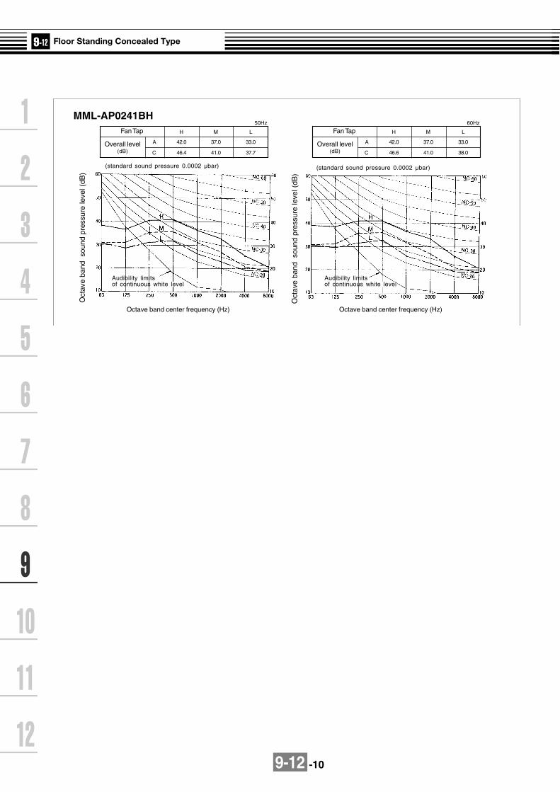
9-12 -10
MML-AP0241BH
Oct
ave
band
sou
nd p
ress
ure
leve
l (dB
)
Octave band center frequency (Hz)
Audibility limitsof continuous white level
(standard sound pressure 0.0002 µbar)
Fan Tap
Overall level(dB)
H
42.0
46.4
A
50Hz
C
M
37.0
41.0
L
33.0
37.7
Oct
ave
band
sou
nd p
ress
ure
leve
l (dB
)
Octave band center frequency (Hz)
Audibility limitsof continuous white level
(standard sound pressure 0.0002 µbar)
Fan Tap
Overall level(dB)
H
42.0
46.6
A
60Hz
C
M
37.0
41.0
L
33.0
38.0
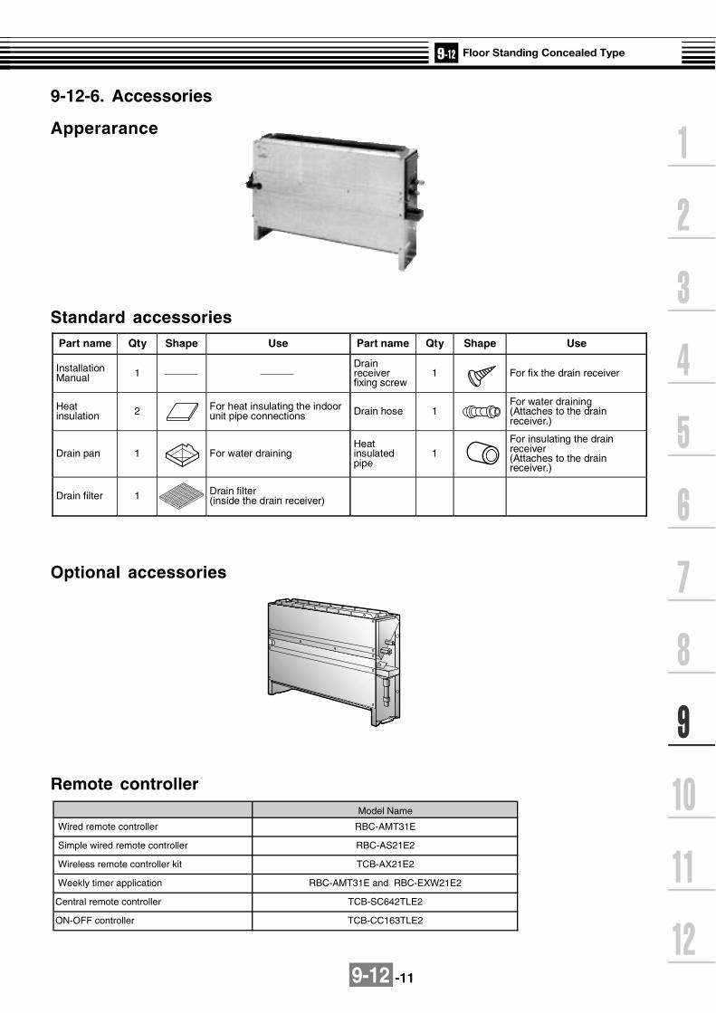
9-12 -11
9-12-6. Accessories
Apperarance
Standard accessories
Remote controller
Optional accessories
Part name Qty Shape Use Part name Qty Shape Use
Installation Manual 1
Drain receiver fixing screw
1 For fix the drain receiver
Heat insulation 2 For heat insulating the indoor
unit pipe connections Drain hose 1 For water draining (Attaches to the drain receiver.)
Drain pan 1 For water draining Heat insulated pipe
1For insulating the drain receiver (Attaches to the drain receiver.)
Drain filter 1 Drain filter (inside the drain receiver)
Wireless remote controller kit
Central remote controller
ON-OFF controller
TCB-SC642TLE2
TCB-CC163TLE2
Weekly timer application
Model Name
RBC-AMT31E
RBC-AS21E2
TCB-AX21E2
RBC-AMT31E and RBC-EXW21E2
Wired remote controller
Simple wired remote controller

9-13 -1
9-13-1. Specifications 50Hz
Specifications (50Hz)
Note 1 : The cooling capacities and electrical characteristics are measured under the conditions specified by JIS B 8615 based on thereference piping. The reference piping consists of 5 m of main piping and 2.5 m of branch piping connected with 0 meter height.
Note 2 : The sound level are measured in an anechoic chamber in accordance with JIS B8616. Normally, the values measured in theactual operating environment become larger than the indicated values due to the effects of external sound.
Note : Rated conditions Cooling : Indoor air temperature 27oC DB/19oC WB, Outdoor air temperature 35oC DBHeating : Indoor air temperature 20oC DB, Outdoor air temperature 7oC DB/6oC WB
Cooling/Heating capacity (Note 1) (kW)
Electricalcharacteristics
Power supply
Running current (A)
Power consumption (kW)
Power factor (%)
Starting current (A)
Model name MMF-
Appearance
Outerdimension Height x Width x Depth (mm)
Total weight (kg)
Heat exchanger
Soundproof/Heat-insulating material
Fan unit
Fan
Standard air flow (High/Mid/Low)
(m3/h)
Motor (W)
Air filter
Controller
Gas side (mm)
Liquid side (mm)
Drain port (Nominal dia. mm)
Connectingpipe
Sound pressure level (Note 2)(High/Mid/Low) (dB(A))
AP0151H
4.5/5.0
1 phase 50Hz 230V (220-240V) (Separate power supply for indoor units is required.)
0.67
0.150
97
0.90
AP0181H
5.6/6.3
AP0241H
7.1/8.0
AP0271H
8.0/9.0
AP0361H
11.2/12.5
AP0481H
14.0/16.0
0.88
0.190
1.29
0.280
1.60
0.350
95
2.10
94
1.10 1.70
W : Silky shade (1Y 8.5/0.5)
1,750 x 600 x 210 1,750 x 600 x 390
6548 49
Finned tube
Non-flammable insulation
Centrifugal fan
900/780/6601,920/1,680/1,380
1,200/1,020/8402,160/1,860/1,560
11037 63 160
Standard filter (Simple filter)
Remote controller
O/ 12.7
O/ 6.4
O/ 15.9
O/ 9.5
20 (Polyvinyl chloride tube)
51/48/4446/43/38 49/45/40 54/50/46
PMV Kit Not available

9-13 -2
60Hz
Model name MMF-
(kW)Cooling/Heating capacity (Note 1)
AP0151H
4.5/5.0
Power supply
Electricalcharacteristics
Running current (A)
Power consumption
Power factor
Starting current
(kW)
(%)
(A)
1 phase 60Hz 220V (Separate power supply for indoor units is required.)
Appearance
Outerdimension
Height x Width xDepth
Total weight
Heat exchanger
Soundproof/Heat-insulating material
Fan
Motor
Standard air flow(High/Mid/Low)Fan unit
Air filter
Controller
Gas side
Liquid side
Drain port
Connectingpipe
Sound pressure level (Note 2)(High/Mid/Low)
(mm)
(kg)
(m3/h)
(W)
(mm)
(mm)
(Nominal dia. mm)
(dB(A))
AP0181H
5.6/6.3
AP0241H
7.1/8.0
AP0271H
8.0/9.0
AP0361H
11.2/12.5
AP0481H
14.0/16.0
0.67 0.90 1.37 1.75
0.146 0.195 0.295 0.380
99 9998
0.90 1.10 1.80 2.30
W : Silky Shade (1Y 8.5/0.5)
1,750 x 600 x 210 1,750 x 600 x 390
48 6549
Finned tube
Non-flammable insulation
Centrifugal fan
900/780/660 1,200/1,020/840 1,920/1,680/1,380 2,160/1,860/1,560
37 63 110 160
Remote controller
Standard filter (Simple filter)
O/ 12.7 O/ 15.9
O/ 6.4 O/ 9.5
20 (Polyvinyl chloride tube)
46/43/38 49/45/40 51/48/44 54/50/46
Note 1 : The cooling capacities and electrical characteristics are measured under the conditions specified by JIS B 8615 based on thereference piping. The reference piping consists of 5 m of main piping and 2.5 m of branch piping connected with 0 meter height.
Note 2 : The sound levels are measured in an anechoic chamber in accordance with JIS B8616. Normally, the values measured inthe actual operating environment become larger than the indicated values due to the effects of external sound.
Note : Rated conditions Cooling : Indoor air temperature 27OC DB/19OC WB, Outdoor air temperature 35OC DBHeating : Indoor air temperature 20OC DB, Outdoor air temperature 7OC DB/6OC WB
PMV Kit Not available
Specifications (60Hz)

9-13 -3
9-13-2. Dimension
MMF-AP0151H, AP0181H, AP0241H, AP0271H
Installation plate
Installation plate
Suction port
Drainhose
Refrigerant piping hole (Back side)(O/ 130 Knockout )
Refrigerant piping hole (Bottom side)(50 x 120 Knockout)
Earth screw (M4)
Dischargeport 80
30 x 3 30 x 3600
Wall
Wall
Wall
Wall
Wall
Floor
Wall
Incase of installing distance is 50mm from wall( )
Lower refrigerant piping port(50 x 120 Knockout hole)
Controlpart
Controlcover
Refrigerant piping port (Both side)(O/ 80 Knockout)
a b
In c
ase
1770
a
In c
ase
1773
b
( )4- lower hole For M8 Screw bolt or M8 Anchor bolt
( )2- lower hole For M8 Screw bolt or M8 Anchor bolt
Front
Fro
nt
Mor
e th
an10
00
Mor
e th
an20
0
Morethan500
Refrigerant piping joint (Gas side A)
Refrigerant piping joint (Liquid side B)
50 x 120 (Square opening)(For under surface piping)O/ 130 Knockout
(For backside piping)
Space required for service(In case of right side piping )
Refrigerant piping position
Details of hole for lower side pipingDetails of hole for back side piping
Note: All dimensions are in mm.
Dimensions
Model
MMF-AP0151H, AP0181H
MMF-AP0241H, AP0271H
A
O/ 12.7
O/ 15.7
B
O/ 6.4
O/ 9.5
Wired remote controller RBC-AMT31E
Simple wired remote controller RBC-AS21E2
Wireless remote controller kit TCB-AX21E2
Weekly timer application RBC-AMT31E and RBC-EXW21E2

9-13 -4
MMF-AP0361H, AP0481H
Installation plate
Dischargeport 80
30 x 3 30 x 3600
Wall
Wall
Incase of installing distance is 50mm from wall( )
Lower refrigerant piping port(50 x 120 Knockout)
Controlpart
Controlcover
Installation plate
Suction portDtain hose
Drain hose
Refrigerant piping hole (Back side)(O/ 130 Knockout)
Refrigerant piping hole (Bottom side)(50 x 120 Knockout)
Earth screw (M4)
Refrigerant piping port (Both side)(O/ 80 Knockout)
Wall
Wall
Wall
Wall
Front
Fro
nt
Mor
e th
an10
00
Mor
e th
an 2
00
Morethan500
Refrigerant piping joint (Gas side O/ 19)
Refrigerant piping joint (Liquid side O/ 9.5)
Gas side
Liquidside
( )4- lower hole For M8 Screw bolt or M8 Anchor bolt
( )2- lower hole For M8 Screw bolt or M8 Anchor bolt
50 x 120 (Square opening)(For under surface piping)
O/ 130 Knockout(For backside piping)
Floor
a b
In c
ase
1770
a
In c
ase
1773
b
Refrigerant piping position
Details of hole for back side piping Details of hole for lower side piping
Space required for service(In case of right side piping )
Wired remote controller RBC-AMT31E
Simple wired remote controller RBC-AS21E2
Wireless remote controller kit TCB-AX21E2
Weekly timer application RBC-AMT31E and RBC-EXW21E2
Note: All dimensions are in mm.
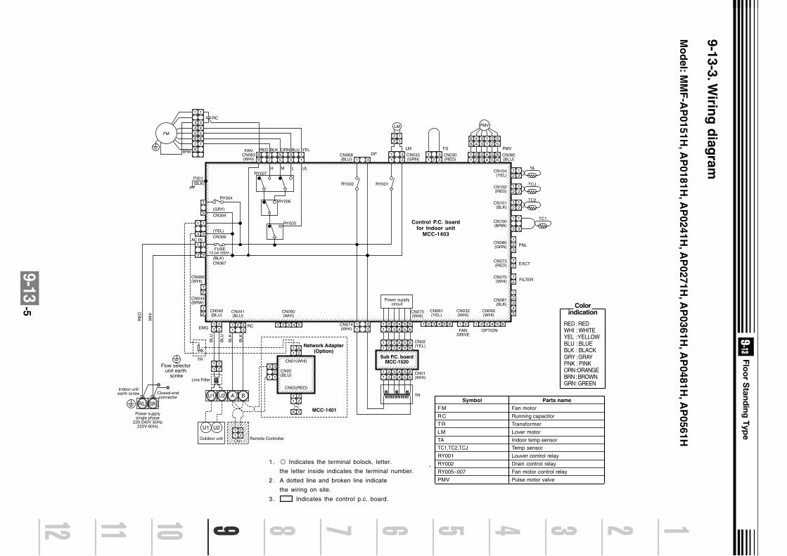
9-13-5
9-13-3. Wirin
g d
iagram
Mo
del: M
MF
-AP
0151H, A
P0181H
, AP
0241H, A
P0271H
, AP
0361H, A
P0481H
, AP
0561H
.
5 3 177
99 5 3 1
RY007P301(BLK)
RY004
(GRY)CN304
(YEL)CN309
(BLK)CN067
FUSET5.0A 250V~
RY006
RY005
H
RED BLK ORN BLU YEL
M L UL
3
1
3
1
3
1
3
1
3
1
RC
BRW
FM
1
3
1
3
CN104(YEL)
TA
21
21
CN102(RED)
TCJ
21
21
CN101(BLK)
CN100(BRW)
1
3
CN080(GRN)
TC2
PNL
EXCT
21
CN073(RED) 2
2
1
FILTERCN070(WHI)
CN081(BLK)
21
21
21
11
22
11
22
11
22
11
2
X Y
2
32
1 1
3
11 2
33 1 2 3 4 5 1 2 3 4 5 6 1 2 1 23 4 5 6 1 2 3 4 5 6
1 2 3 4 5 6
21
43
5
21
TC1
CN066(WHI)
AC IN
CN044(BRW)
CN040(BLU)
Outdoor unit Remote Controller
Power supplysingle phase
220-240V 50Hz220V 60Hz
Indoor unitearth screw Closed-end
connector
Line Filter
CN01(WHI)
CN03(RED)
CN02(BLU)
CN041(BLU)
CN050(WHI)
CN061(YEL)
CN032(WHI)
FANDRIVE
OPTION
CN060(WHI)
EMG
BLU
BLU
RE
D
WH
I
BLK
BLK
RC
TR
U1
U1 U2
U2 A B
Network Adapter(Option)
MCC-1401
11
22
CN1
11
33CN074
(WHI)
CN075(WHI)
Power supplycircuit
TR
1 3CN068(BLU)
FANCN083(WHI)
RY002
DP11
33 CN033
(GRN)
RY001
LM
CN082(BLU)
PMV
LM
11
2 33 CN030
(RED)
FS
22
11
1 2 3 4 5 61 2 3 4 5 6
1 234 561 234 56
PMV
R(L) S(N)
3
1
3
1
654
654
787
1 2 3 4 5 61 2 3 4 5 6
1 2 3 4 5 61 2 3 4 5 6
CN01(WHI)
CN02(YEL)
Sub P.C. boardMCC-1520
Flow selector unit earth
screw
Colorindication
RED : REDWHI : WHITEYEL : YELLOWBLU : BLUEBLK : BLACKGRY : GRAYPNK : PINKORN :ORANGEBRN : BROWNGRN : GREEN
SymbolFM
RC
TR
LM
TA
TC1,TC2,TCJ
RY001
RY002
RY005~007
PMV
Parts nameFan motor
Running capacitor
Transformer
Lover motor
Indoor temp sensor
Temp sensor
Louver control relay
Drain control relay
Fan motor control relay
Pulse motor valve
1. Indicates the terminal bolock, letter.
the letter inside indicates the terminal number.
2. A dotted line and broken line indicate
the wiring on site.
3. Indicates the control p.c. board.
Control P.C. boardfor Indoor unit
MCC-1403

9-13 -6
TC : Total Capacity (kW) SHC : Sensible Heat Capacity (kW)Indoor air temp.
Unit Outdoor 16.0˚CWB 18.0˚CWB 19.0˚CWB 20.0˚CWB 22.0˚CWB 24.0˚CWBsize air temp. 23˚CDB 26˚CDB 27˚CDB 28˚CDB 30˚CDB 32˚CDB
˚CDB TC SHC TC SHC TC SHC TC SHC TC SHC TC SHC10.0 4.1 3.2 4.4 3.4 4.5 3.4 4.6 3.4 4.9 3.4 5.1 3.312.0 4.1 3.2 4.4 3.4 4.5 3.4 4.6 3.4 4.9 3.4 5.1 3.314.0 4.1 3.2 4.4 3.4 4.5 3.4 4.6 3.4 4.9 3.4 5.1 3.316.0 4.1 3.2 4.4 3.4 4.5 3.4 4.6 3.4 4.9 3.4 5.1 3.318.0 4.1 3.2 4.4 3.4 4.5 3.4 4.6 3.4 4.9 3.4 5.1 3.320.0 4.1 3.2 4.4 3.4 4.5 3.4 4.6 3.4 4.9 3.4 5.1 3.321.0 4.1 3.2 4.4 3.4 4.5 3.4 4.6 3.4 4.9 3.4 5.1 3.3
015 23.0 4.1 3.2 4.4 3.4 4.5 3.4 4.6 3.4 4.9 3.4 5.1 3.325.0 4.1 3.2 4.4 3.4 4.5 3.4 4.6 3.4 4.9 3.4 5.1 3.327.0 4.1 3.2 4.4 3.4 4.5 3.4 4.6 3.4 4.9 3.4 5.1 3.329.0 4.1 3.2 4.4 3.4 4.5 3.4 4.6 3.4 4.9 3.4 5.1 3.331.0 4.1 3.2 4.4 3.4 4.5 3.4 4.6 3.4 4.9 3.4 5.1 3.333.0 4.1 3.2 4.4 3.4 4.5 3.4 4.6 3.4 4.9 3.4 5.1 3.335.0 4.1 3.2 4.4 3.4 4.5 3.4 4.6 3.4 4.9 3.4 5.1 3.337.0 4.0 3.1 4.3 3.3 4.4 3.3 4.5 3.3 4.8 3.3 5.0 3.239.0 3.9 3.0 4.2 3.2 4.3 3.2 4.4 3.2 4.7 3.2 4.9 3.110.0 5.1 3.9 5.4 4.1 5.6 4.1 5.8 4.1 6.1 4.1 6.4 4.012.0 5.1 3.9 5.4 4.1 5.6 4.1 5.8 4.1 6.1 4.1 6.4 4.014.0 5.1 3.9 5.4 4.1 5.6 4.1 5.8 4.1 6.1 4.1 6.4 4.016.0 5.1 3.9 5.4 4.1 5.6 4.1 5.8 4.1 6.1 4.1 6.4 4.018.0 5.1 3.9 5.4 4.1 5.6 4.1 5.8 4.1 6.1 4.1 6.4 4.020.0 5.1 3.9 5.4 4.1 5.6 4.1 5.8 4.1 6.1 4.1 6.4 4.021.0 5.1 3.9 5.4 4.1 5.6 4.1 5.8 4.1 6.1 4.1 6.4 4.0
018 23.0 5.1 3.9 5.4 4.1 5.6 4.1 5.8 4.1 6.1 4.1 6.4 4.025.0 5.1 3.9 5.4 4.1 5.6 4.1 5.8 4.1 6.1 4.1 6.4 4.027.0 5.1 3.9 5.4 4.1 5.6 4.1 5.8 4.1 6.1 4.1 6.4 4.029.0 5.1 3.9 5.4 4.1 5.6 4.1 5.8 4.1 6.1 4.1 6.4 4.031.0 5.1 3.9 5.4 4.1 5.6 4.1 5.8 4.1 6.1 4.1 6.4 4.033.0 5.1 3.9 5.4 4.1 5.6 4.1 5.8 4.1 6.1 4.1 6.4 4.035.0 5.1 3.9 5.4 4.1 5.6 4.1 5.8 4.1 6.1 4.1 6.4 4.037.0 5.0 3.8 5.3 4.0 5.5 4.0 5.7 4.0 6.0 4.0 6.3 3.939.0 4.9 3.6 5.2 3.9 5.4 3.9 5.5 3.9 5.9 3.8 6.1 3.710.0 6.4 5.0 6.9 5.3 7.1 5.3 7.3 5.3 7.7 5.3 8.1 5.112.0 6.4 5.0 6.9 5.3 7.1 5.3 7.3 5.3 7.7 5.3 8.1 5.114.0 6.4 5.0 6.9 5.3 7.1 5.3 7.3 5.3 7.7 5.3 8.1 5.116.0 6.4 5.0 6.9 5.3 7.1 5.3 7.3 5.3 7.7 5.3 8.1 5.118.0 6.4 5.0 6.9 5.3 7.1 5.3 7.3 5.3 7.7 5.3 8.1 5.120.0 6.4 5.0 6.9 5.3 7.1 5.3 7.3 5.3 7.7 5.3 8.1 5.121.0 6.4 5.0 6.9 5.3 7.1 5.3 7.3 5.3 7.7 5.3 8.1 5.1
024 23.0 6.4 5.0 6.9 5.3 7.1 5.3 7.3 5.3 7.7 5.3 8.1 5.125.0 6.4 5.0 6.9 5.3 7.1 5.3 7.3 5.3 7.7 5.3 8.1 5.127.0 6.4 5.0 6.9 5.3 7.1 5.3 7.3 5.3 7.7 5.3 8.1 5.129.0 6.4 5.0 6.9 5.3 7.1 5.3 7.3 5.3 7.7 5.3 8.1 5.131.0 6.4 5.0 6.9 5.3 7.1 5.3 7.3 5.3 7.7 5.3 8.1 5.133.0 6.4 5.0 6.9 5.3 7.1 5.3 7.3 5.3 7.7 5.3 8.1 5.135.0 6.4 5.0 6.9 5.3 7.1 5.3 7.3 5.3 7.7 5.3 8.1 5.137.0 6.3 4.9 6.7 5.2 7.0 5.2 7.2 5.2 7.6 5.1 7.9 5.039.0 6.2 4.7 6.6 5.0 6.8 5.0 7.0 5.0 7.4 4.9 7.8 4.8
9-13-4. Sensible capacity table(MMF-AP***H)
Cooling capacity

9-13 -7
Cooling capacity (cont.)Indoor air temp.
Unit Outdoor 16.0˚CWB 18.0˚CWB 19.0˚CWB 20.0˚CWB 22.0˚CWB 24.0˚CWBsize air temp. 23˚CDB 26˚CDB 27˚CDB 28˚CDB 30˚CDB 32˚CDB
˚CDB TC SHC TC SHC TC SHC TC SHC TC SHC TC SHC10.0 7.3 5.6 7.8 5.9 8.0 5.9 8.2 5.9 8.7 5.8 9.1 5.712.0 7.3 5.6 7.8 5.9 8.0 5.9 8.2 5.9 8.7 5.8 9.1 5.714.0 7.3 5.6 7.8 5.9 8.0 5.9 8.2 5.9 8.7 5.8 9.1 5.716.0 7.3 5.6 7.8 5.9 8.0 5.9 8.2 5.9 8.7 5.8 9.1 5.718.0 7.3 5.6 7.8 5.9 8.0 5.9 8.2 5.9 8.7 5.8 9.1 5.720.0 7.3 5.6 7.8 5.9 8.0 5.9 8.2 5.9 8.7 5.8 9.1 5.721.0 7.3 5.6 7.8 5.9 8.0 5.9 8.2 5.9 8.7 5.8 9.1 5.7
027 23.0 7.3 5.6 7.8 5.9 8.0 5.9 8.2 5.9 8.7 5.8 9.1 5.725.0 7.3 5.6 7.8 5.9 8.0 5.9 8.2 5.9 8.7 5.8 9.1 5.727.0 7.3 5.6 7.8 5.9 8.0 5.9 8.2 5.9 8.7 5.8 9.1 5.729.0 7.3 5.6 7.8 5.9 8.0 5.9 8.2 5.9 8.7 5.8 9.1 5.731.0 7.3 5.6 7.8 5.9 8.0 5.9 8.2 5.9 8.7 5.8 9.1 5.733.0 7.3 5.6 7.8 5.9 8.0 5.9 8.2 5.9 8.7 5.8 9.1 5.735.0 7.3 5.6 7.8 5.9 8.0 5.9 8.2 5.9 8.7 5.8 9.1 5.737.0 7.1 5.5 7.6 5.8 7.8 5.8 8.1 5.8 8.5 5.7 8.9 5.639.0 7.0 5.2 7.4 5.6 7.7 5.6 7.9 5.6 8.4 5.5 8.8 5.410.0 10.2 7.6 10.9 8.0 11.2 8.0 11.5 8.0 12.2 7.9 12.8 7.712.0 10.2 7.6 10.9 8.0 11.2 8.0 11.5 8.0 12.2 7.9 12.8 7.714.0 10.2 7.6 10.9 8.0 11.2 8.0 11.5 8.0 12.2 7.9 12.8 7.716.0 10.2 7.6 10.9 8.0 11.2 8.0 11.5 8.0 12.2 7.9 12.8 7.718.0 10.2 7.6 10.9 8.0 11.2 8.0 11.5 8.0 12.2 7.9 12.8 7.720.0 10.2 7.6 10.9 8.0 11.2 8.0 11.5 8.0 12.2 7.9 12.8 7.721.0 10.2 7.6 10.9 8.0 11.2 8.0 11.5 8.0 12.2 7.9 12.8 7.7
036 23.0 10.2 7.6 10.9 8.0 11.2 8.0 11.5 8.0 12.2 7.9 12.8 7.725.0 10.2 7.6 10.9 8.0 11.2 8.0 11.5 8.0 12.2 7.9 12.8 7.727.0 10.2 7.6 10.9 8.0 11.2 8.0 11.5 8.0 12.2 7.9 12.8 7.729.0 10.2 7.6 10.9 8.0 11.2 8.0 11.5 8.0 12.2 7.9 12.8 7.731.0 10.2 7.6 10.9 8.0 11.2 8.0 11.5 8.0 12.2 7.9 12.8 7.733.0 10.2 7.6 10.9 8.0 11.2 8.0 11.5 8.0 12.2 7.9 12.8 7.735.0 10.2 7.6 10.9 8.0 11.2 8.0 11.5 8.0 12.2 7.9 12.8 7.737.0 10.0 7.4 10.6 7.9 11.0 7.8 11.3 7.8 12.0 7.8 12.5 7.639.0 9.8 7.1 10.4 7.5 10.8 7.5 11.1 7.5 11.7 7.5 12.3 7.310.0 12.7 9.3 13.6 9.9 14.0 9.9 14.4 9.9 15.3 9.8 16.0 9.612.0 12.7 9.3 13.6 9.9 14.0 9.9 14.4 9.9 15.3 9.8 16.0 9.614.0 12.7 9.3 13.6 9.9 14.0 9.9 14.4 9.9 15.3 9.8 16.0 9.616.0 12.7 9.3 13.6 9.9 14.0 9.9 14.4 9.9 15.3 9.8 16.0 9.618.0 12.7 9.3 13.6 9.9 14.0 9.9 14.4 9.9 15.3 9.8 16.0 9.620.0 12.7 9.3 13.6 9.9 14.0 9.9 14.4 9.9 15.3 9.8 16.0 9.621.0 12.7 9.3 13.6 9.9 14.0 9.9 14.4 9.9 15.3 9.8 16.0 9.6
048 23.0 12.7 9.3 13.6 9.9 14.0 9.9 14.4 9.9 15.3 9.8 16.0 9.625.0 12.7 9.3 13.6 9.9 14.0 9.9 14.4 9.9 15.3 9.8 16.0 9.627.0 12.7 9.3 13.6 9.9 14.0 9.9 14.4 9.9 15.3 9.8 16.0 9.629.0 12.7 9.3 13.6 9.9 14.0 9.9 14.4 9.9 15.3 9.8 16.0 9.631.0 12.7 9.3 13.6 9.9 14.0 9.9 14.4 9.9 15.3 9.8 16.0 9.633.0 12.7 9.3 13.6 9.9 14.0 9.9 14.4 9.9 15.3 9.8 16.0 9.635.0 12.7 9.3 13.6 9.9 14.0 9.9 14.4 9.9 15.3 9.8 16.0 9.637.0 12.5 9.2 13.3 9.7 13.7 9.7 14.1 9.7 15.0 9.6 15.6 9.439.0 12.2 8.8 13.0 9.3 13.4 9.3 13.8 9.3 14.6 9.2 15.3 9.0

9-13 -8
SHC : Sensible Heat Capacity (kW)
UnitOutdoor Indoor air temp. ˚CDB
size air temp. 16.0 18.0 20.0 22.0 24.0
˚CWB SHC SHC SHC SHC SHC-15.0 3.1 3.1 3.0 2.9 2.9-13.0 3.3 3.3 3.2 3.1 3.0-11.0 3.6 3.5 3.4 3.3 3.2-10.0 3.7 3.6 3.5 3.4 3.3-8.0 3.9 3.8 3.7 3.6 3.5-6.0 4.1 4.0 3.9 3.8 3.7-4.0 4.3 4.2 4.1 4.0 3.9
015 -2.0 4.5 4.4 4.3 4.2 4.10.0 4.7 4.6 4.5 4.4 4.22.0 4.8 4.7 4.6 4.5 4.44.0 5.0 4.9 4.8 4.7 4.66.0 5.2 5.1 5.0 4.9 4.88.0 5.2 5.1 5.0 4.9 4.8
10.0 5.2 5.1 5.0 4.9 4.812.0 5.2 5.1 5.0 4.9 4.814.0 5.2 5.1 5.0 4.9 4.8-15.0 3.9 3.9 3.8 3.7 3.6-13.0 4.2 4.1 4.0 3.9 3.8-11.0 4.5 4.4 4.3 4.2 4.1-10.0 4.6 4.5 4.4 4.3 4.2-8.0 4.9 4.8 4.7 4.6 4.4-6.0 5.1 5.0 4.9 4.8 4.7-4.0 5.4 5.3 5.2 5.0 4.9
018 -2.0 5.6 5.5 5.4 5.3 5.10.0 5.9 5.8 5.6 5.5 5.32.0 6.1 6.0 5.9 5.7 5.64.0 6.3 6.2 6.1 5.9 5.86.0 6.6 6.4 6.3 6.1 6.08.0 6.6 6.4 6.3 6.1 6.0
10.0 6.6 6.4 6.3 6.1 6.012.0 6.6 6.4 6.3 6.1 6.014.0 6.6 6.4 6.3 6.1 6.0-15.0 5.0 4.9 4.8 4.7 4.6-13.0 5.3 5.2 5.1 5.0 4.9-11.0 5.7 5.6 5.5 5.3 5.2-10.0 5.8 5.7 5.6 5.5 5.3-8.0 6.2 6.1 5.9 5.8 5.6-6.0 6.5 6.4 6.2 6.1 5.9-4.0 6.8 6.7 6.6 6.4 6.2
024 -2.0 7.1 7.0 6.9 6.7 6.50.0 7.4 7.3 7.1 7.0 6.82.0 7.7 7.6 7.4 7.3 7.14.0 8.0 7.9 7.7 7.5 7.36.0 8.3 8.2 8.0 7.8 7.68.0 8.3 8.2 8.0 7.8 7.6
10.0 8.3 8.2 8.0 7.8 7.612.0 8.3 8.2 8.0 7.8 7.614.0 8.3 8.2 8.0 7.8 7.6
Heating capacity

9-13 -9
UnitOutdoor Indoor air temp. ˚CDB
size air temp. 16.0 18.0 20.0 22.0 24.0
˚CWB SHC SHC SHC SHC SHC-15.0 5.6 5.5 5.4 5.3 5.1-13.0 6.0 5.9 5.8 5.6 5.5-11.0 6.4 6.3 6.1 6.0 5.8-10.0 6.6 6.5 6.3 6.2 6.0-8.0 7.0 6.8 6.7 6.5 6.3-6.0 7.3 7.2 7.0 6.9 6.7-4.0 7.7 7.5 7.4 7.2 7.0
027 -2.0 8.0 7.9 7.7 7.5 7.30.0 8.4 8.2 8.0 7.8 7.62.0 8.7 8.5 8.4 8.2 7.94.0 9.0 8.9 8.7 8.5 8.36.0 9.4 9.2 9.0 8.8 8.68.0 9.4 9.2 9.0 8.8 8.6
10.0 9.4 9.2 9.0 8.8 8.612.0 9.4 9.2 9.0 8.8 8.614.0 9.4 9.2 9.0 8.8 8.6-15.0 7.8 7.7 7.5 7.3 7.2-13.0 8.3 8.2 8.0 7.8 7.6-11.0 8.9 8.7 8.5 8.3 8.1-10.0 9.1 9.0 8.8 8.6 8.3-8.0 9.7 9.5 9.3 9.1 8.8-6.0 10.2 10.0 9.8 9.5 9.3-4.0 10.7 10.5 10.2 10.0 9.7
036 -2.0 11.1 10.9 10.7 10.5 10.20.0 11.6 11.4 11.2 10.9 10.62.0 12.1 11.9 11.6 11.3 11.04.0 12.6 12.3 12.1 11.8 11.56.0 13.0 12.8 12.5 12.2 11.98.0 13.0 12.8 12.5 12.2 11.9
10.0 13.0 12.8 12.5 12.2 11.912.0 13.0 12.8 12.5 12.2 11.914.0 13.0 12.8 12.5 12.2 11.9-15.0 10.0 9.8 9.6 9.4 9.1-13.0 10.7 10.5 10.3 10.0 9.7-11.0 11.4 11.1 10.9 10.7 10.4-10.0 11.7 11.5 11.2 11.0 10.7-8.0 12.4 12.1 11.9 11.6 11.3-6.0 13.0 12.8 12.5 12.2 11.9-4.0 13.6 13.4 13.1 12.8 12.4
048 -2.0 14.3 14.0 13.7 13.4 13.00.0 14.9 14.6 14.3 14.0 13.62.0 15.5 15.2 14.9 14.5 14.14.0 16.1 15.8 15.4 15.1 14.76.0 16.7 16.3 16.0 15.6 15.28.0 16.7 16.3 16.0 15.6 15.2
10.0 16.7 16.3 16.0 15.6 15.212.0 16.7 16.3 16.0 15.6 15.214.0 16.7 16.3 16.0 15.6 15.2
Heating capacity (cont.)

9-13 -10
9-13-5. Air throw distance chart
1 2 3 4 5 6 7 8
2.7
2.0
1.0
1.5m/s 1.0m/s 0.7m/s0.5m/s
1 2 3 4 5 6 7 8
2.7
2.0
1.0
1.5m/s 1.0m/s
0.5m/s
1 2 3 4 5 6 7 8
2.7
2.0
(m)
(m)
(m)
(m)
(m)
(m)
(m)
(m)
1.0
2.0m/s1.0m/s1.5m/s
0.5m/s
1 2 3 4 5 6 7 8
2.7
2.0
1.0
1.5m/s1.5m/s1.5m/s1.0m/s
MMF-AP0151H, AP0181H MMF-AP0241H, AP0271H
MMF-AP0361H MMF-AP0481H,AP0561H
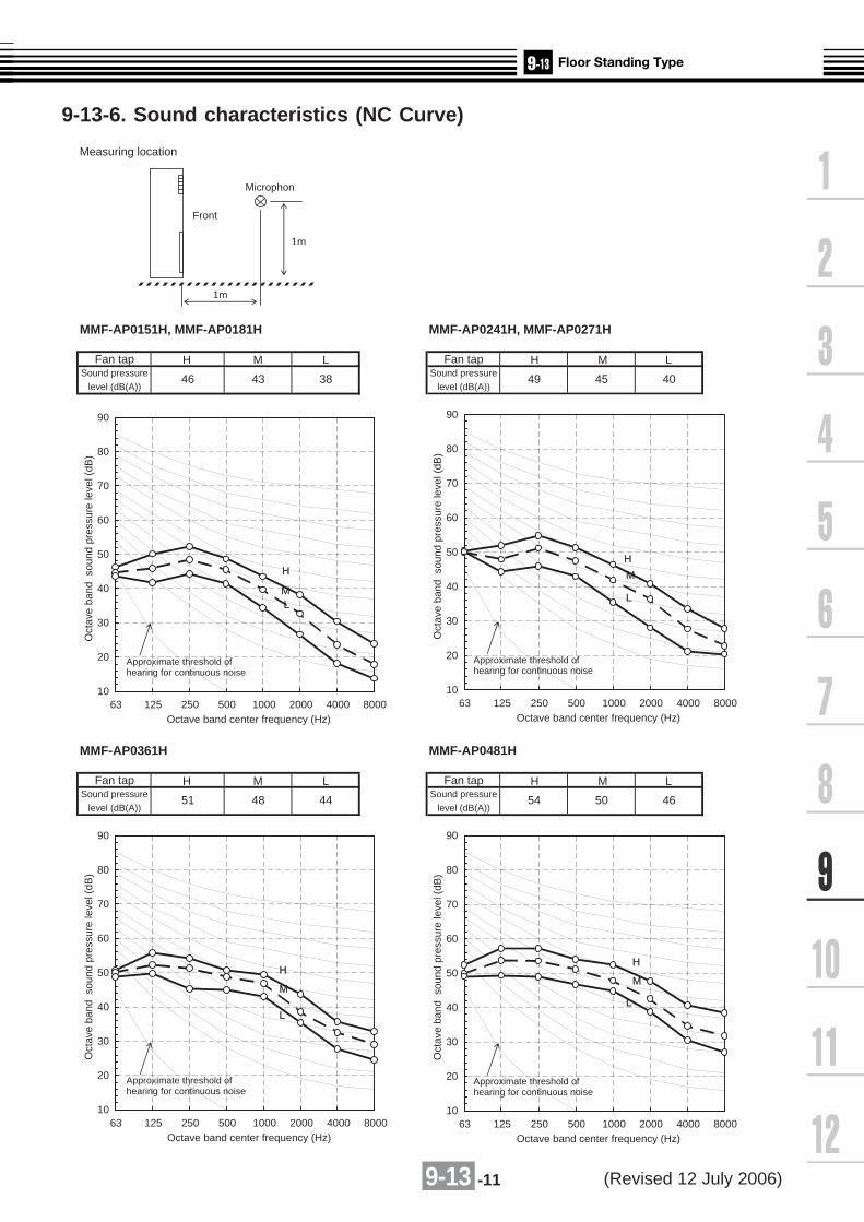
9-13 -11
Measuring location
MMF-AP0151H, MMF-AP0181H MMF-AP0241H, MMF-AP0271H
Fan tap Fan tapSound pressure Sound pressure
level (dB(A)) level (dB(A))
MMF-AP0361H MMF-AP0481H
Fan tap Fan tapSound pressure Sound pressure
level (dB(A)) level (dB(A))
43 38 49 45 40
H M L
51 48 44 54 50 46
46
10
20
30
40
50
60
70
80
90
63 125 250 500 1000 2000 4000 8000Octave band center frequency (Hz)
Oct
ave
band
sou
nd p
ress
ure
leve
l (dB
)
Approximate threshold ofhearing for continuous noise
L
H
M
10
20
30
40
50
60
70
80
90
63 125 250 500 1000 2000 4000 8000Octave band center frequency (Hz)
Oct
ave
band
sou
nd p
ress
ure
leve
l (dB
)
Approximate threshold ofhearing for continuous noise
L
H
M
10
20
30
40
50
60
70
80
90
63 125 250 500 1000 2000 4000 8000Octave band center frequency (Hz)
Oct
ave
band
sou
nd p
ress
ure
leve
l (dB
)
Approximate threshold ofhearing for continuous noise
L
H
M
10
20
30
40
50
60
70
80
90
63 125 250 500 1000 2000 4000 8000Octave band center frequency (Hz)
Oct
ave
band
sou
nd p
ress
ure
leve
l (dB
)
Approximate threshold ofhearing for continuous noise
L
H
M
Front
1m
1m
Microphon
H M L
H M LH M L
9-13-6. Sound characteristics (NC Curve)
(Revised 12 July 2006)

9-13 -12
9-13-7. Accessories
Apperarance
Standard accessories
Remote controller
Optional accessories
Weekly timer application
Model Name
RBC-AMT31E
RBC-AS21E2
TCB-AX21E2
RBC-AMT31E and RBC-EXW21E2
Wired remote controller
Simple wired remote controller
Wireless remote controller kit
Central remote controller
ON-OFF controller
TCB-SC642TLE2
TCB-CC163TLE2
Attached position Part name Qty Shape Stored position
Upper part of main unit Bracket for fixing to wall 1
Installation Manual 1
Thermal insulator 2
Screw bolt 4 (2)
Accessory bag
Thermal insulator 2
Lower part of main unit Bracket for fixing to floor 2
Quantities in the above table are for MMF-AP0361, AP0481 and AP0561 models.The brackets for fixing to the floor are already mounted on the indoor unit.
Indoor unit
Base for transportation
Using 4 (2) screw bolts, fix to the base.
(Revised 19 May 2006)

9-14 -1
MonitoringON/OFF status (for indoor unit)Alarm status (system & indoor unit stop)
ON/OFF commandAir conditioner can be turned ON/OFFby external signals.The external ON/OFF signals will initiate the signals shown below.
Function
Display
Operation
Interface
RemoteController
Non-voltageON /OFF continious signal
ON /OFF
COM
ModelName
Appearance Features
TC
B-I
FC
B-4
E2
Start and stop of the air conditioner is possibleby a external signal and indication ofoperation/alarm externally.
Application
[1] Remote location ON/OFF control box
Outside view
(NOTE) Do not install the accessory parts at the following locations.
Inside viewFix this control box to the place besides the indoor unit.
1. Location where combustible gas may leak2. Location where direct sunlight shines3. Location with high humidity such as bathroom, kitchen, etc.4. Location with high levels of dust5. Location where rain or dew drops such as outdoors6. Location in 1m-range of a TV or radio
No.
1
2
3
4
5
6
Case unit
Note : All dimensions are in mm
SpecificationName
Case cover
Harness to connect indoor unit P.C. board
Harness for indication cable
Harness for power supply
Harness for ON/OFF command
Galvanized steel 0.8t
Galvanized steel 0.8t
CN61 connector
UL1015 AWG18 tip-insulation type butt connector
3-core, 0.75mm2
UL1015 AWG18 tip-insulation type butt connector
1
2
3
200
22 78 78 22 Approx. 300 6663.6
22 78 78 22
6- 5.5 mounting hole
Approx.1500
6
156
146.
9
170
5
4
Dimension

9-14 -2
Indoor unit type Accessory parts name Model Application model Remarks
Ceiling panel
Super Long Life Filter
High Efficiency Filter 65
High Efficiency Filter 90
Fresh air and FilterChamber
Fresh air inlet Box
Auxiliary fresh air Flange
Spacer for heightadjustment
Air discharge direction kit
Ceiling panel
Spacer for height adjustment
Fresh Air Chamber
Fresh Air Intel Box
Air Discharge Direction Kit
Ceiling panel
Ceiling panel
Front air discharge unit
Auxiliary fresh air flange
High Efficiency Filter 65
High Efficiency Filter 90
Ceiling panel
Suction Canvas
Filter Chamber
Filter kit for underside
High Efficiency Filter 65
High Efficiency Filter 90
Long Life Pre-Filter
Filter Chamber
Drain pump kit
Drain pump kit
Elbow piping kit
RBC-U21PG(W)-E2
TCB-LF1601UE2
TCB-UFM1601UE
TCB-UFH1601UE
TCB-GFC1601UE2
TCB-GB1601UE2
TCB-FF101URE2
TCB-SP1601UE
TCB-BC1601UE
RBC-UM11PG(W)E
***
***
***
***
RBC-UW136PG
RBC-UW266PG
RBC-UW466PG
RBC-US21PGE
TCB-BU21HWE
TCB-FF101URE
TCB-UFM11BFCE
TCB-UFM21BFCE
TCB-UFM11BE
TCB-UFM21BE
TCB-UFM31BE
TCB-UFM41BE
TCB-UFH51BFCE
TCB-UFH61BFCE
TCB-UFH51BE
TCB-UFH61BE
TCB-UFH71BE
TCB-UFH81BE
RBC-UD281PE(W)
RBC-UD501PE(W)
RBC-UD801PE(W)
RBC-UD1401PE(W)
TCB-CA281BE
TCB-CA501BE
TCB-CA801BE
TCB-CA1401BE
TCB-FC281BE
TCB-FC501BE
TCB-FC801BE
TCB-FC1401BE
TCB-FK281BE
TCB-FK501BE
TCB-FK801BE
TCB-FK1401BE
TCB-UFM1D-1E
TCB-UFM2D-1E
TCB-UFH5D-1E
TCB-UFH6D-1E
TCB-PF1D-1E
TCB-PF2D-1E
TCB-FCY21DE
TCB-FCY31DE
TCB-FCY51DE
TCB-DP31DE
TCB-DP22CE2
TCB-KP12CE2
TCB-KP22CE2
Be used with TCB-GFC1601UE2
AP0071-0121
AP0151-0301
AP0481
AP0071-0121/AP0241-0301
AP0151-0181/AP0361-0481
AP0071-0121
AP0151-0181
AP0241-0301
AP0361-0481
AP0071-0121/AP0241-0301
AP0151-0181/AP0361-0481
AP0071-0121
AP0151-0181
AP0241-0301
AP0361-0481
AP0071-0121
AP0151-0181
AP0241-0301
AP0361-0481
AP0071-0121
AP0151-0181
AP0241-0301
AP0361-0481
AP0071-0121
AP0151-0181
AP0241-0301
AP0361-0481
AP0071-0121
AP0151-0181
AP0241-0301
AP0361-0481
AP0181/0481
AP0241-0361
AP0181/0481
AP0241-0361
AP0181/0481
AP0241-0361
AP0181
AP0241-0361
AP0481
AP0181-0481
AP0151-0481
AP0151-0181
AP0241-0481
Compact 4-way AirDischarge Cassette(600 x 600) Type
2-way Air DischargeCassette Type
1-way Air DischargeCassette Type
Concealed Duct Type
Concealed Duct HighStatic Pressure Type
Under Ceiling Type
Required accessory
Optional
Required accessory
Optional
Required accessory
Required accessory
Optional
Optional
Optional
Optional
Be used with TCB-GFC1601UE2
Three-piece set
China market only
AP0241-AP0301 use two pcs.
AP0361-AP0481 use two pcs.
For underside suction
AP0241-AP0301 use two pcs.
AP0361-AP0481 use two pcs.
For underside suction
(Half panel for undersidesuction)
For underside suction
For rear suction
AP0481 use two pcs.
Use two pcs.
AP0481 use two pcs.
Use two pcs.
AP0481 use two pcs.
Use two pcs.
*Required accessories when using Drain Pump Kit
4-way Air DischargeCassette Type
Panels and accessories

10 -1
Allowable length of refrigerant piping
• Connecting direction of refrigerant pipeWhen connecting pipes, be careful of direction of themain unit. Be sure to install the main unit so that[ ] mark in the label directs upward.For connection of the refrigerant pipes, follow thearrow mark in the label and connect pipes afterconfirming directions of indoor unit and outdoor unit.
Piping material and dimensions
PMV Kit
Indoor unit
PMV Kit Refrigerant pipe
2 m to 10 m
Indoor unit
PMV Kit
NO GOOD OK
Note)Do not connect two or more indoor units to one PMV Kit.Arrange one indoor unit and one PMV Kit set to 1 by 1.
Label
Attached joint Attached joint
Model name
RBM-PMV0361E
RBM-PMV0901E
Indoor unit capacity type
007, 009, 012 type
015, 018 type
024 type
Diameter of refrigerant pipe
Ø6.4
Ø6.4
Ø9.5
Notes
Indoor unit
PMV-Kit (RBM-PMV0361E/RBM-PMV0901E) shall be required for quiter place application asan optional to reduce refrigerant sound especially in oil retrieval control or in transient operation as start up.
Model name Indoor unit capacity type Diameter of refrigerant pipeRBM-PMV0361E 007,009,012 type O/ 6.4
RBM-PMV0901E 015,018 type O/ 6.4024 type O/ 9.5
10-1. Selection

10 -2
Set the hanging bolts for supporting pipes which are mounted at front and rear sides of PMVKit at within 1m intervals.
1 m or less
Hanging boltHanging bolt
PMV Kit
Refrigerant pipe
Fixation after connection pipes
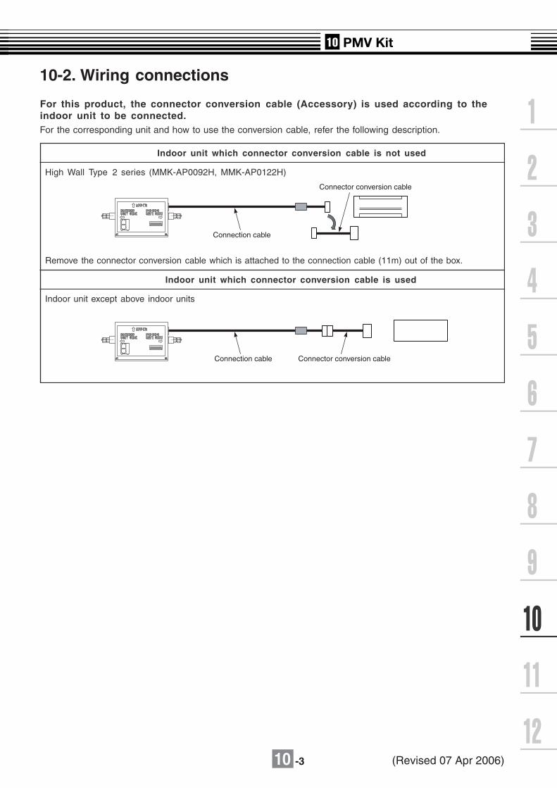
10 -3
10-2. Wiring connections
For this product, the connector conversion cable (Accessory) is used according to theindoor unit to be connected.For the corresponding unit and how to use the conversion cable, refer the following description.
Connection cable
Connection cable Connector conversion cable
Connector conversion cable
Indoor unit which connector conversion cable is not used
High Wall Type 2 series (MMK-AP0092H, MMK-AP0122H)
Remove the connector conversion cable which is attached to the connection cable (11m) out of the box.
Indoor unit which connector conversion cable is used
Indoor unit except above indoor units
(Revised 07 Apr 2006)

10 -4
10-3. Dimension
PMV Kit
RBM-PMV0361E, RBM-PMV0901E
55 226 55
port (Liquid pipe)Refrigerant pipe connecting
port (Liquid pipe)Refrigerant pipe connecting
(accessory)Connection cable
30
26
36
76
58
30
76
161
50or
mor
e
or m
ore
50
RBM-PMV0901E(When attached joint are used)200 or more
RBM-PMV0361E,PMV0901E
200 or more
5555
50 o
r m
ore
Box cover
Check port450 x 450
500
or m
ore
200 or more200 or more
7373
or
mor
e50
50or
mor
e
Binding band L
Binding band M
Installation image
Binding band M
Binding band LBinding band M
Refrigerant pipe (Gas side)Heat insulating pipe
Heat insulating pipe
Refrigerant pipe (Liquid side)
Refrigerant pipe (Liquid side)
Binding band M
Note: All dimensions are in mm.


11 -1
-
(kW)
(kW)
(A)
(kW)
(%)
(kW/kW)
(A)
(A)
(kW)
(%)
(kW/kW)
(A)
(mm)
(kg)
(kW)
(kW)
(m3/h)
(kg)
(MPa)
(mm)
(mm)
(m)
(m)
(m)
(m)
(m)
(dB(A))
(dB(A))
MMY
Equivalent to 4HP
MCY-MAP0401HT
12.1
12.5
13.2
2.82
93
4.29
12.5
2.71
94
4.61
2.3 3.1 4.2
5,820
15.9 19.1
Flare Brazing
6,120
Finned tube
7.2
Open : 3.73 Close : 2.9
*5
9.5
Flare
15
6,420
18.3
4.00
95
4.00
Soft start
117
Shilky shade (Munsell 1Y8.5/0.5)
Hermetic Type
Propeller fan (Quantity 2)
0.063 + 0.063
Height 1,340/Width 900/Depth 320
22.2
4.85
95
3.71
16.1
3.47
94
4.03
Soft start
21.4
4.63
94
3.35
14.0
16.0
1 phase 60Hz 220V
15.5
18.0
Equivalent to 5HP
MCY-MAP0501HT
Inverter unit
Equivalent to 6HP
MCY-MAP0601HT
11-1. Specifications 50Hz
Specifications (50Hz)Equivalent HP
Model name
Outdoor unit type
Cooling capacity (*1)
Standard heating capacity (*1)
Power supply (*2)
Heat exchanger
Refrigerant R410A (Charged refrigerant amount) (*3)
High-pressure switch
Protective devices
Gas side
Liquid side
Discharge gas side
Liquid side
Max. equivalent length
Max. real length
Max. total pipe length (Real length)
Max. Height between indoor units
Max. No. of connected indoor units
Sound pressure level (Cooling/Heating) *3
125 (If the total bend length exceeds 125m, use the max equivalentlength as the standard.)
Outdoor unit is higher than indoor unit : 30
Outdoor unit is lower than indoor unit : 20
Shield wire 1.25mm2 2cores, up to 1000mShield wire 2.0mm2 2cores, up to 2000m
*1 : Rated conditions Cooling : Indoor air temperature 27oC DB/19oC WB, Outdoor air temperature 35oC DBHeating : Indoor air temperature 20oC DB, Outdoor air temperature 7oC DB/6oC WB
The standard piping means that main pipe length is 5 m, branching pipe length 2.5 m of branch piping connected with a 0 meterheight.
*2 : The source voltage must not fluctuate more than ±10%.*3 : The amount does not consider extra piping lengths. Refrigerant must be added on site in accordance with the actual piping length.*4 : The maximum total piping length indicates the sum of one-way piping lengths on the liquid side or gas side.*5 : Discharge temp. sensor, Suction temp. sensor, Compressor case thermostat, High-pressure switch, Over-current sensor,
High-pressure sensor, Low pressure sensor, Over-current relay.
6
49/50
46/48
8
50/52
46/48
9
51/53
47/49
Control wiringTotal wire length(indoor unit- indoor unit/ indoor unit-outdoor unit control wiring,central control wiring)
Real length between PMV Kit and indoor unit 2-10
Night operation (Sound reduction)control*4
Electricalcharacteristics(*1)
Cooling
Heating
Running current
Power consumption
Power factor
EER (Energy Efficiency Ratio)
Starting current
Running current
Power consumption
Power factor
EER (Energy Efficiency Ratio)
Starting current
External dimension
Total weight
Color
Compressor
Fan unit
Type
Motor output
Fan
Motor output
Air volume
Refrigerant pipingspecifications (*4)
Connecting port dia
Connecting method
(Revised 07 Apr 2006)

11 -2
-
(kW)
(kW)
(A)
(kW)
(%)
(kW/kW)
(A)
(A)
(kW)
(%)
(kW/kW)
(A)
(mm)
(kg)
(kW)
(kW)
(m3/h)
(kg)
(MPa)
(mm)
(mm)
(m)
(m)
(m)
(m)
(m)
(dB(A))
(dB(A))
MMY
Equivalent to 4HP
MCY-MAP0401HT2D
12.1
12.5
13.8
2.82
93
4.29
13.1
2.71
94
4.61
2.3 3.1 4.2
5,820
15.9 19.1
Flare Brazing
6,120
Finned tube
7.2
Open : 3.73 Close : 2.9
*5
9.5
Flare
15
6,420
19.1
4.00
95
4.00
Soft start
117
Shilky shade (Munsell 1Y8.5/0.5)
Hermetic Type
Propeller fan (Quantity 2)
0.063 + 0.063
Height 1,340/Width 900/Depth 320
23.2
4.85
95
3.71
16.8
3.47
94
4.03
Soft start
22.4
4.63
94
3.35
14.0
16.0
1 phase 60Hz 220V
15.5
18.0
Equivalent to 5HP
MCY-MAP0501HT2D
Inverter unit
Equivalent to 6HP
MCY-MAP0601HT2D
Equivalent HP
Model name
Outdoor unit type
Cooling capacity (*1)
Standard heating capacity (*1)
Power supply (*2)
Electricalcharacteristics(*1)
Cooling
Heating
Running current
Power consumption
Power factor
EER (Energy Efficiency Ratio)
Starting current
Running current
Power consumption
Power factor
EER (Energy Efficiency Ratio)
Starting current
External dimension
Total weight
Color
Compressor
Fan unit
Type
Motor output
Fan
Motor output
Air volume
Heat exchanger
Refrigerant R410A (Charged refrigerant amount) (*3)
High-pressure switch
Protective devices
Refrigerant pipingspecifications (*4)
Connecting port dia
Connecting method
Gas side
Liquid side
Discharge gas side
Liquid side
Max. equivalent length
Max. real length
Max. total pipe length (Real length)
Max. Height between indoor units
Max. No. of connected indoor units
Sound pressure level (Cooling/Heating) *3
125 (If the total bend length exceeds 125m, use the max equivalentlength as the standard.)
Outdoor unit is higher than indoor unit : 30
Outdoor unit is lower than indoor unit : 20
Shield wire 1.25mm2 2cores, up to 1000mShield wire 2.0mm2 2cores, up to 2000m
6
49/50
46/48
8
50/52
46/48
9
51/53
47/49
Control wiringTotal wire length(indoor unit- indoor unit/ indoor unit-outdoor unit control wiring,central control wiring)
Real length between PMV Kit and indoor unit 2-10
Night operation (Sound reduction)control*4
*1 : Rated conditions Cooling : Indoor air temperature 27oC DB/19oC WB, Outdoor air temperature 35oC DBHeating : Indoor air temperature 20oC DB, Outdoor air temperature 7oC DB/6oC WB
The standard piping means that main pipe length is 5 m, branching pipe length 2.5 m of branch piping connected with a 0 meterheight.
*2 : The source voltage must not fluctuate more than ±10%.*3 : The amount does not consider extra piping lengths. Refrigerant must be added on site in accordance with the actual piping length.*4 : The maximum total piping length indicates the sum of one-way piping lengths on the liquid side or gas side.*5 : Discharge temp. sensor, Suction temp. sensor, Compressor case thermostat, High-pressure switch, Over-current sensor,
High-pressure sensor, Low pressure sensor, Over-current relay.
60Hz
Specifications (60Hz)

11 -3
11-2. Dimension
MCY-MAP0401HT, MCY-MAP0501HT, MCY-MAP0601HT,MCY-MAP0401HT2D, MCY-MAP0501HT2D, MCY-MAP0601HT2D
Note: All dimensions are in mm.
i
Knockout(Drain) Drain hole(O/ 20x88)
Knockout(Drain)
Drain hole(O/ 25)B lege
Mounting bolt hole(O/ 12 x 17slot)
(O/ 12 x 17U-shape cut-out)
(O/ 9.5 flare at liquid side)
(O/ 15.9 flare at gas side)
Knockout for lower piping
Diameter of refrigerant pipe
Space required for service
365
8060
32 45
46
165
600
Name Model name Gas side Liquid sideControl wiring andpiping hole
MCY-MAP0401HT*
O/ 19.1
O/ 15.9 (Flare)O/ 15.9 (Flare)
O/ 9.5 (Flare)O/ 9.5 (Flare)
O/ 9.5 (Flare)
2-O/ 12 x 17U -shape cut-out(F or M 10 Anchor bolt)
2-O/ 12 x 17 slot(F or M 10 Anchor bolt)
Air inlet
300or more
500or more
Air outlet
150or more
150
or
more
Mnimumdistance up to wall
MCY-MAP0601HT*
MCY-MAP0501HT*
Power supply wiring hole Knockout hole O/ 38
Notes
Mounting bolt holeDetails of A legs Details of B legs
Refrigerant pipe connecting port
Refrigerant pipe connecting port
A legs
Airin let
Airin let
Air outlet
Blazing connection withattached joint socket.
307314
2795
Z Z View
60
60
587
86 7
15467
350
625
900
600 1081506026
29 90 191 20
43
12
320
400161
5827
89 2513
40
2121
40
43
40
40
17.5
40 40
54
70
17.5
17.5
365
722
718

11 -4
11-3. Units center of gravity
Weight (kg)Main unit
MCY-AP0401HTMCY-AP0401HT2DMCY-AP0501HTMCY-AP0501HT2DMCY-AP0601HTMCY-AP0601HT2D
Model name H (mm) W (mm) D (mm)
1171340 900 320
440 200
610
365150 600

11 -5
11-4. Wiring diagram
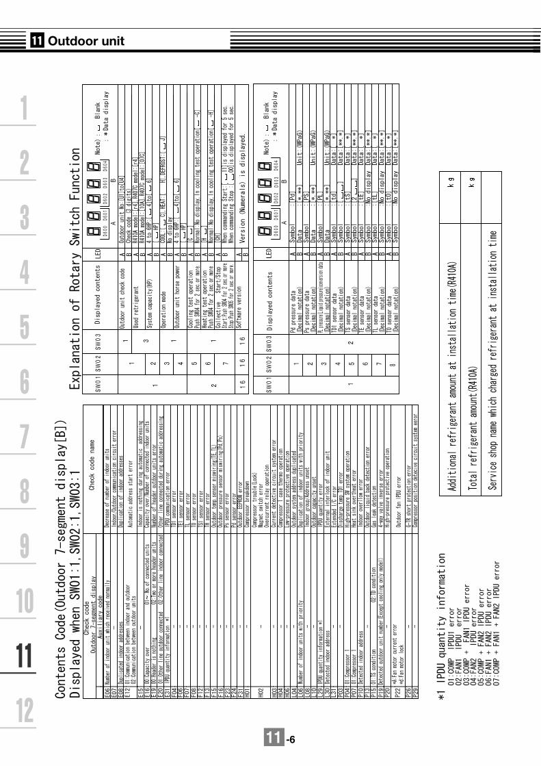
11 -6

11 -7
11-5. Part Load Performance
MCY-MAP0401HT*
CoolingCompressor + Outdoor fan motor Power consumption (kW)
OutdoorTemperature
DB˚C
Outdoor unit 100%
CoolingCapacity
(kW)
100%Load
90%Load
80%Load
70%Load
60%Load
50%Load
40 11.5 3.07 2.58 2.14 1.76 1.43 1.1635 12.1 2.82 2.37 1.97 1.62 1.31 1.0630 12.1 2.39 2.01 1.68 1.39 1.14 0.9325 12.1 2.03 1.72 1.44 1.20 0.99 0.8220 12.1 1.81 1.53 1.29 1.07 0.89 0.7415 12.1 1.64 1.39 1.17 0.98 0.81 0.68
Indoor air temperature conditions : 27 ˚CDB, 19˚CWBIndoor unit fan speed : High
HeatingCompressor + Outdoor fan motor Power consumption (kW)
OutdoorTemparature
DB˚C WB˚C15 13.7 12.5 2.38 2.02 1.69 1.38 1.11 0.8611 9.8 12.5 2.53 2.14 1.79 1.46 1.17 0.907 6 12.5 2.71 2.29 1.91 1.56 1.24 0.961 0.3 11.2 2.59 2.19 1.82 1.49 1.18 0.91-5 -5.6 9.9 2.46 2.08 1.73 1.41 1.13 0.87-10 -10.5 8.7 2.35 1.99 1.66 1.35 1.08 0.83
Indoor air temperature conditions : 20 ˚CDBIndoor unit fan speed : High
70%Load
60%Load
50%Load
Outdoor unit 100%
HeatingCapacity
(kW)
100%Load
90%Load
80%Load

11 -8
MCY-MAP0501HT*
CoolingCompressor + Outdoor fan motor Power consumption (kW)
OutdoorTemperature
DB˚C
Outdoor unit 100%
CoolingCapacity
(kW)
100%Load
90%Load
80%Load
70%Load
60%Load
50%Load
40 13.3 3.78 3.10 2.52 2.03 1.63 1.3435 14.0 3.47 2.80 2.28 1.85 1.50 1.1930 14.0 2.90 2.39 1.95 1.59 1.30 1.0825 14.0 2.45 2.03 1.67 1.37 1.13 0.9620 14.0 2.17 1.80 1.48 1.22 1.02 0.8715 14.0 1.96 1.63 1.35 1.12 0.93 0.80
Indoor air temperature conditions : 27 ˚CDB, 19˚CWBIndoor unit fan speed : High
HeatingCompressor + Outdoor fan motor Power consumption (kW)
OutdoorTemparature
DB˚C WB˚C15 13.7 16.0 3.46 2.98 2.49 2.04 1.64 1.2711 9.8 16.0 3.71 3.16 2.64 2.16 1.72 1.337 6 16.0 4.00 3.39 2.82 2.30 1.83 1.411 0.3 14.4 3.82 3.23 2.69 2.20 1.75 1.35-5 -5.6 12.6 3.63 3.07 2.56 2.09 1.66 1.28-10 -10.5 11.1 3.47 2.94 2.45 2.00 1.59 1.23
Indoor air temperature conditions : 20 ˚CDBIndoor unit fan speed : High
70%Load
60%Load
50%Load
Outdoor unit 100%
HeatingCapacity
(kW)
100%Load
90%Load
80%Load

11 -9
MCY-MAP0601HT*
CoolingCompressor + Outdoor fan motor Power consumption (kW)
OutdoorTemperature
DB˚C
Outdoor unit 100%
CoolingCapacity
(kW)
100%Load
90%Load
80%Load
70%Load
60%Load
50%Load
40 14.7 5.05 4.14 3.36 2.70 2.18 1.7835 15.5 4.63 3.74 3.04 2.47 2.01 1.5930 15.5 3.71 3.19 2.61 2.12 1.73 1.4425 15.5 3.03 2.71 2.22 1.83 1.51 1.2720 15.5 2.64 2.40 1.98 1.63 1.36 1.1615 15.5 2.37 2.17 1.80 1.49 1.24 1.06
Indoor air temperature conditions : 27 ˚CDB, 19˚CWBIndoor unit fan speed : High
HeatingCompressor + Outdoor fan motor Power consumption (kW)
OutdoorTemparature
DB˚C WB˚C15 13.7 18.0 4.21 3.53 2.90 2.33 1.81 1.3511 9.8 18.0 4.50 3.77 3.10 2.49 1.93 1.447 6 18.0 4.85 4.06 3.34 2.67 2.08 1.541 0.3 16.2 4.63 3.88 3.18 2.55 1.98 1.47-5 -5.6 14.2 4.40 3.68 3.03 2.43 1.88 1.40-10 -10.5 12.5 4.21 3.52 2.89 2.32 1.80 1.34
Indoor air temperature conditions : 20 ˚CDBIndoor unit fan speed : High
70%Load
60%Load
50%Load
Outdoor unit 100%
HeatingCapacity
(kW)
100%Load
90%Load
80%Load
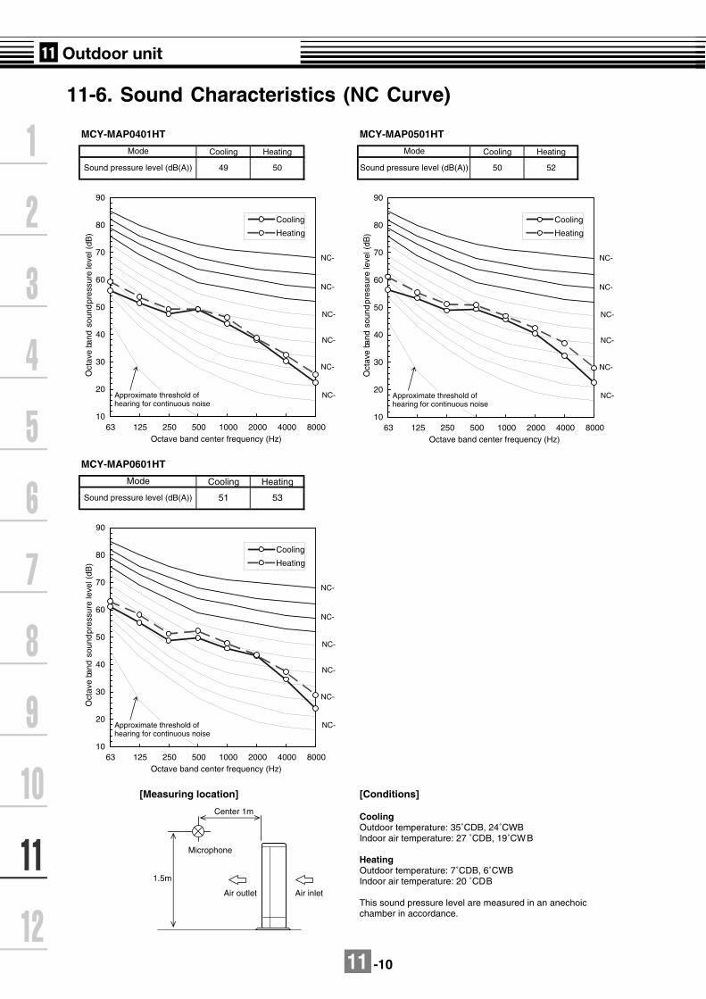
11 -10
11-6. Sound Characteristics (NC Curve)
MCY-MAP0401HT MCY-MAP0501HT
Cooling Heating Cooling Heating
MCY-MAP0601HT
Cooling Heating
[Measuring location] [Conditions]
CoolingOutdoor temperature: 35˚CDB, 24˚CWBIndoor air temperature: 27 ˚CDB, 19˚CWB
HeatingOutdoor temperature: 7˚CDB, 6˚CWBIndoor air temperature: 20 ˚CDB
This sound pressure level are measured in an anechoicchamber in accordance.
Mode Mode
Sound pressure level (dB(A)) 49 50 Sound pressure level (dB(A)) 50 52
Mode
Sound pressure level (dB(A)) 51 53
10
20
30
40
50
60
70
80
90
63 125 250 500 1000 2000 4000 8000Octave band center frequency (Hz)
Oct
ave
band
sou
nd p
ress
ure
leve
l (dB
)
Cooling
Heating
NC-
NC-
NC-
NC-Approximate threshold ofhearing for continuous noise
NC-
NC-
10
20
30
40
50
60
70
80
90
63 125 250 500 1000 2000 4000 8000Octave band center frequency (Hz)
Oct
ave
band
sou
nd p
ress
ure
leve
l (dB
)
Cooling
Heating
NC-
NC-
NC-
NC-Approximate threshold ofhearing for continuous noise
NC-
NC-
10
20
30
40
50
60
70
80
90
63 125 250 500 1000 2000 4000 8000Octave band center frequency (Hz)
Oct
ave
band
sou
nd p
ress
ure
leve
l (dB
)
Cooling
Heating
NC-
NC-
NC-
NC-Approximate threshold ofhearing for continuous noise
NC-
NC-
Air outlet Air inlet
Center 1m
Microphone
1.5m

11 -11
[Night operation (sound reduction) control ]
MCY-MAP0401HT,MCY-MAP0501HT MCY-MAP0601HT
Cooling Heating Cooling Heating
[Measuring location] [Conditions]
CoolingOutdoor temperature: 25˚CDB, 16˚CWBIndoor air temperature: 27 ˚CDB, 19˚CWB
HeatingOutdoor temperature: 7˚CDB, 6˚CWBIndoor air temperature: 20 ˚CDB
This sound pressure level are measured in an anechoicchamber in accordance.
47 49
Mode Mode
Sound pressure level (dB(A)) 46 48 Sound pressure level (dB(A))
10
20
30
40
50
60
70
80
90
63 125 250 500 1000 2000 4000 8000Octave band center frequency (Hz)
Oct
ave
band
sou
nd p
ress
ure
leve
l (dB
)
Cooling
Heating
NC-
NC-
NC-
NC-Approximate threshold ofhearing for continuous noise
NC-
NC-
10
20
30
40
50
60
70
80
90
63 125 250 500 1000 2000 4000 8000Octave band center frequency (Hz)
Oct
ave
band
sou
nd p
ress
ure
leve
l (dB
)
Cooling
Heating
NC-
NC-
NC-
NC-Approximate threshold ofhearing for continuous noise
NC-
NC-
Air outlet Air inlet
Center 1m
Microphone
1.5m

11 -12
11-7. Accesories
11-7-1. Branching joints and headers
Branch headerRBM-HY1043E, HY1083E
Gas side
Liquid side
O /D
B 80 x n
Insulator
50A
C
O/ E
Insulator
O /D
B 80 x n BO /
DA O/ E
74.5
61
RBM-HY1043E
RBM-HY1083E
6 x 4, 9 x 4, 14 x 1,
18 x 1, 70 x 1
1 x 4, 6 x 1, 9 x 1
6 x 8, 9 x 8, 14 x 1,
18 x 1 70 x 1
1 x 8, 6 x 1, 9 x 1
Gas side
Liquid side
Gas side
Liquid side
380
360
700
680
90
60
90
60
83.6
_
83.6
_
22.2
15.9
22.2
15.9
Accessory socket x Q’tyModel A B C ØD
15.9
9.5
15.9
9.5
ØE
3
3
7
7
n
Note: All dimensions are in mm.

11 -13
Y-shape branch jointRBM-BY53E, BY103E
Note: All dimensions are in mm.
Gas side
Liquid side
O / C
A
O / B
O / D
O / D
Insulator
RBM-BY53E
5 x 2, 54 x 2, 9 x 1, 51 x 1
1 x 2, 5 x 1
Gas side
Liquid side
250
200
80
70
15.9
12.7
12.7
9.5
Accessory socket x Q’tyModel A B ØC ØD
B
O / D
O / C
A
O / D
Insulator
(Revised 12 July 2006)

11 -14
11-7-2. Application controls of outdoor unit
ModelName
Appearance Function
TC
B-P
CD
M2E
Power peak-cut Control
Application
Size : 71 x 85
*Install this optionalP.C. board in theinverter assemblyof the outdoor unit.
Note : The P.C. boards of outdoor unit (TCB-PCDM2E, TCB-PCMO2E, TCB-PCIN2E) can be installed up to two boards.
SW07-Bit2 OFFInput SW07-Bit1 OFF SW07-Bit1 ON Display
Relay (L1)SW1 SW2 Capacity Current Capacity Current
OFF ON 100% (Nomal)
100%(Nomal)
100%(Normal)
100%(Normal)
OFF
ON OFF 0% (stop) 0% (stop) Up to 60% Up to 80% ON
CAUTION)
(COS =100%)
(Non-indutive load)
Be sure to prepare a non-voltege point for each terminal.Display Relay capacity of "OPERATION"
Below AC240V 0.5AWhen connecting load such as relay coil to "L1" load, insert thenoise surge absorber.Below DC24V 1AWhen connecting load such as relay coil to "L1" load, insert the bypass circuit.
!
[Standard funciton]
In case of pulse signal
Be sure to prepare the point of contact for each terminal.The time of the pulse signal is more than 100msec.Don't switch on both SW1 and SW2 terminal simultaneously.
:Display lamp surging powerpeak-cutcontrol.
CN513
I/F P.C Boad
Local Supply
ON
COM
TCB-PCDM2E
OFF
COM
SW1
SW2
DisplayRelay
PJ17
OPERATION Power Supply
ConnectionCable
SW07Bit2 OFF
ON
OFF
SW1 SW2
L1
Outdoor unit
Shield wire
L1
Wiring
Input wiring
Output wiring
Type
Shield wire
Shield wire
Len gth
Up to 500m
Up to 200m
Up to 400m
Size
2-core or 3-core, 0.75mm2
2-core, 0.75mm2 *
2-core, 1.5mm2 ** In conformity with design 60245 IEC 57
Normal currentOutdoor unit capacity type MCY- 0401 type 0501 type 0601 type
Normal current (Maxim running current) 25A 28A 31A
FeatureThe upper limit capacity and current of the outdoor unit isrestricted based on the demand request signal from outside.
Function / Electric wiring diagramTwo type control can be selected by setting SW07 on theinterface P.C. board of the outdoor unit.
(Revised 19 May 2006)

11 -15
ModelName
Appearance Function
TC
B-P
CD
M2E
Application
Size : 71 x 85
*Install this optionalP.C. board in theinverter assemblyof the outdoor unit.
ON OFF Up to 80% Up to 80% Up to 85% Up to 90% ON
OFF ON Up to 60% Up to 70% Up to 75% Up to 80% ON
ON ON 0% (stop) 0% (stop) Up to 60% Up to 70% ON
CAUTION)Be sure to prepare non voltage continuous point of contact for eachterminal.Display Relay capacity of "OPERATION"
Below AC240V 0.5A (COS =100%)When connecting load such as relay coil to "L1" load, insert thenoise surge absorber.Below DC24V 1A (Non-indutive load)When connecting load such as relay coil to "L1" load, insert thebypass circuit.
!
SW07-Bit2 ON
[Expansion function]
CN513
OFF
COM
SW2
PJ17
OFF
I/F P.C Boad
Local Supply
ON
COM
TCB-PCDM2E
SW1
DisplayRelay
Power Supply
ConnectionCable
ON
SW07Bit2 ON L1
OPERATIO
Outdoor unit
Shield wire
L1 :Display lamp surging power peak-cut control.
Input SW07-Bit1 OFF SW07-Bit1 ON DisplayRelay (L1)SW1 SW2 Capacity Current Capacity Current
OFF OFF 100% (Nomal)
100%(Nomal)
100%(Normal)
100%(Normal)
OFF
(Revised 19 May 2006)

11 -16
ModelName
Appearance FunctionT
CB
-PC
MO
2E Application
Size : 55.5 x 60
*Install this optionalP.C. board in theinverter assemblyof the outdoor unit.
External master ON/OFF control
FeatureThe outdoor unit starts or stops the system.
Function
SMC : Input signal for startSMH : Input signal for stop
Terminal Input signal Operation
SMC Starts all indoor units.
Stops all indoor units.
Ensure terminal contacts are securely fixed.
This control is activated when the input signal increases or decreases(The increasing or decreasing signal needs to be held for a minimum of100m/sec in order to activate the control.)
SMH
CN512
COM
COOL
TCB-PCMO2E
HEAT
SMC
SMHPJ17
Local Supply
I/F P.C Boad
ConnectionCable
Outdoor unit
Shield wire
ON
OFFON
OFF
ON
OFF ON
OFF
Night operation (Sound reduction) control
FeatureSound level can be reduced by restricting the compressor andfan speeds.
Function
SMC : Cooling mode designated input switchTerminal Input signal Operation
SMC
Night operation control
Usual Operation
This control is activated when the input signal increases or decreases.(The increasing or decreasing signal needs to be held for a minimum of100m/sec in order to activate the control).
CN508
COMSMC
PJ17
COOL
TCB-PCMO2E
HEAT
Local Supply
I/F P.C Boad
ConnectionCable
Shield wire
Outdoor unit
(Revised 19 May 2006)
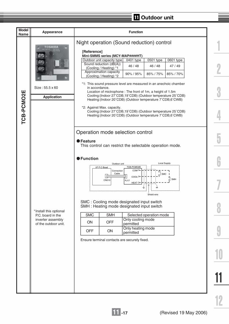
11 -17
ModelName
Appearance Function
TC
B-P
CM
O2E Application
Size : 55.5 x 60
*Install this optionalP.C. board in theinverter assemblyof the outdoor unit.
Operation mode selection control
FeatureThis control can restrict the selectable operation mode.
Function
SMC : Cooling mode designated input switchSMH : Heating mode designated input switch
ON
OFF
Only cooling modepermitted
Ensure terminal contacts are securely fixed.
OFF
ONOnly heating modepermitted
CN510
COM
SMC
SMHPJ17
COOL
TCB-PCMO2E
HEAT
I/F P.C Boad
Local Supply
ConnectionCable
Outdoor unit
Shield wire
SMC SMH Selected operation mode
Night operation (Sound reduction) control
[Reference]Mini-SMMS series (MCY-MAP####HT)Outdoor unit capacity type 0401 type 0501 type 0601 typeSound reduction (dB(A))
(Cooling / Heating) *1
*1: This sound pressure level are measured in an anechoic chamberin accordance.Location of mictrophone : The front of 1m, a height of 1.5mCooling:(Indoor 27˚CDB,19˚CDB) (Outdoor temperature 25˚CDB)Heating:(Indoor 20˚CDB) (Outdoor temperature 7˚CDB,6˚CWB)
*2: Against Max. capacity.Cooling:(Indoor 27˚CDB,19˚CDB) (Outdoor temperature 25˚CDB)Heating:(Indoor 20˚CDB) (Outdoor temperature 7˚CDB,6˚CWB)
46 / 48 46 / 48 47 / 49
Approximation capacity(Cooling / Heating) *2
90% / 95% 85% / 75% 85% / 70%
(Revised 19 May 2006)

11 -18
ModelName
Appearance FunctionT
CB
-PC
IN2E
Error / Operation output control
Application
Size : 73.0 x 79
*Install this optionalP.C. board in to theinverter assemblyof the headeroutdoor unit.
Ensure terminal contacts are securely fixed.Display Relay capacity of "OPERATION" and "EMG"Below AC240V 0.5A(COSφ=100%)When connecting a load such as a relay coil to "L1,L2",insert the noise surge absorber.Below DC24V 1A(Non-inductive load)When connecting a load such as a relay coil to "L1,L2",insert the byass circuit.
I/F P.C. Board* TCB-PCIN2E Local Supply
Power Supply
ConnectionCable
Power Supply
CN511 PJ20DisplayRelay
DisplayRelay
EMG
L1
L2
OPERATION
L1 : Operation monitoring lampL2 : Error monitoring lamp
(Revised 19 May 2006)

11 -19
TCB-PCDM2E
TCB-PCMO2E
TCB-PCIN2E
Dimension
85 75
TerminalScrew M3 x 6
TerminalScrew M4 x 8
4-4O/ hole
71
61
6979
6373
4- 4 hole
Terminal (Screw M3 )
TerminalScrew M3 x 6
55.5
45.5
60 50
4-4O/ hole

11 -20
Placing position
Install this optional P.C. board to the back side of the Interface P.C. board on outdoor unit.Be sure to turn off the power switch before installing.
(1) If the screw of the position shown in Fig. 1 is removed and an upper right hook is slipped, an interface boardwill open.
(2) Place this P.C. board by using the support of the electric component box.There are four installation holes to place the support of the electric component box.
Wiring
(1) Refer to the "Electric wiring diagram" when wiring.
(2) Be sure to use the shield wire to prevent noise trouble, and perform the grounding at both sides of shield wires.(3) Fix the output wiring with the wire clamp. (Wire clamp is accessory of optional P.C.board.)
[Fig.1]
Interface P.C. board
Hook part
Screw
Screw
[Electric component box]
Optional P.C. board
TCB-PCDM2E (left side) TCB-PCIN2E (right side) TCB-PCMO2E (both side)
[Fig.2] [Fig.3]
·Up to a total of two boards
Electric component box
Grounding (screw is accessory)
Wire clamp (accessory)
Output wiring
[Fig.4]
Optional P.C. board of outdoor unit installation
(Revised 12 July 2006)

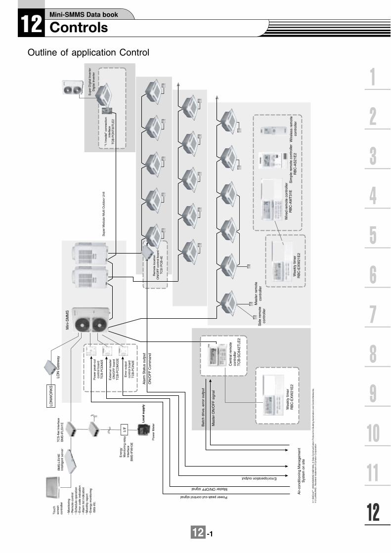
12 -1
Bat
ch d
rive,
err
or o
utpu
t
Mas
ter
ON
/OF
F s
igna
l
Wire
d re
mot
e co
ntro
ller
RB
C-A
MT
31E
Sid
e re
mot
e co
ntro
ller
Mas
ter
rem
ote
cont
rolle
r
Wee
kly
timer
R
BC
-EX
W21
E2
Wee
kly
timer
R
BC
-EX
W21
E2
Sim
ple
rem
ote
cont
rolle
rR
BC
-AS
21E
2W
irele
ss r
emot
e co
ntro
ller
Cen
tral
rem
ote
cont
rolle
rT
CB
-SC
642T
LE2
Sup
er D
igita
l Inv
erte
rD
igita
l Inv
erte
r
"1:1
mod
el"
conn
ectio
n in
terf
ace
TC
B-P
CN
T30
TLE
2
Rem
ote
loca
tion
ON
/OF
F c
ontr
ol b
oard
TC
B IP
CB
-4E
1 B
AC
netT
M: A
NS
l/AS
HR
AE
135Ð
1995
, A D
ata
Com
mun
iCat
ion
Pro
toco
l for
Bul
ding
Aut
omat
ion
and
Con
troI
Net
wor
ks.
2 Lo
NW
oRK
S¨ , R
esis
terd
trad
emar
k of
Ech
elon
Cor
pora
tion
Power peak-cut control signal
Error/operation output
Master ON/OFF signal
Air-
cond
ition
ing
Man
agem
ent
Sys
tem
on
site
LON
WO
RK
S
LON
Gat
eway
Pow
er p
eak-
cut
cont
rol b
oard
T
CB
-PC
DM
2E
Ext
erna
l mas
ter
ON
/OF
F b
oard
TC
B-P
CD
MO
2E
Err
or o
utpu
tco
ntro
l boa
rdT
CB
-PC
IN2E
Tou
chsc
reen
cont
rolle
r
Mon
itorin
g R
emot
e co
ntro
l S
ched
ule
oper
atio
n E
rror
cod
e in
dica
tion
Ala
rm li
st in
dica
tion
Mon
thly
rep
ort
Ene
rgy
mon
itorin
g d
ata
etc.
Inte
llige
nt s
erve
rT
CS
-Net
Inte
rfac
e
Ene
rgy
Mon
itorin
g re
lay
Inte
rfac
e
Sup
er M
odul
ar M
ulti
Out
door
Uni
t
Min
i-SM
MS
I/F
BM
S-L
SV
4EB
MS
-IF
LSV
1E
BM
S-I
FW
H3E
Pow
er M
eter
Ala
rm S
tatu
s ou
tput
ON
/OF
F C
omm
and
Lo
cal s
up
ply
Outline of application Control

12 -2
12-1. Applications
12-1-1. Applications for indoor remote controller
1-1
Basic function System diagram Model
1-2
GROUP controlOne remote controllercan control a group ofup to a maximum. 8indoor units.Operatingon the same setting
IndividualcontrolAir conditioner isindividually operatedat a distance.
Wired remote controllerRBC-AMT31E
Simple remote controllerRBC-AS21E2
Wired remote controllerRBC-AMT31E
Simple remote controllerRBC-AS21E2
Wireless remote controllerkitTCB-AX21U(W)-E2RBC-AX22CE2TCB-AX21E2
Indoorunit
Remotecontroller
Possible up to Max.total length 500m
Main remote controller
Indoorunit
WirelessRemote
controller
Receiver unit
Wireless remote controller
(((
Indoorunit
Indoorunit
Indoorunit
Indoorunit
Remotecontroller
Max.8 indoor units
Possible up to Max.total length 500m

12 -3
Basic function System diagram Model
1-3
1-4
Two remote controlAir conditioner iscontrolled by tworemote controllers intwo locations.
Control byweekly timerWeekly scheduleoperation
Wired remote controllerRBC-AMT31E
Simple remote controllerRBC-AS21E2
Wireless remote controllerkitTCB-AX21U(W)-E2RBC-AX22CE2TCB-AX21E2
Wired remote controllerRBC-AMT31E
+
Weekly timerRBC-EXW21E2
Indoorunit
Remotecontroller
Master
Possible up to Max.total length 500m
Wired system
Remotecontroller
Side
Master
Wireless system
Indoorunit
Wirelessremote
controller 1
Side
Wirelessremote
controller 2
(((
( ( (
Wired & Wirelesscombination control(Either one of the two controllers can be set as side control).
Indoorunit
Remotecontroller
Wirelessremote
controller
( ( (
Weekly timer function Setting of ON-OFF
3 times par dayTimer operation time is displayed. Holiday period
Indoorunit
Remotecontroller
Weekly timer
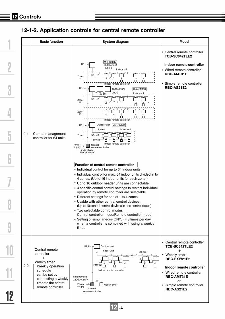
12 -4
12-1-2. Application controls for central remote controller
Basic function System diagram Model
2-1
2-2
Central managementcontroller for 64 units
Central remotecontroller +Weekly timer
Weekly operationschedulecan be set byconnecting a weeklytimer to the centralremote controller
Central remote controllerTCB-SC642TLE2
Indoor remote controller
Wired remote controllerRBC-AMT31E
Simple remote controllerRBC-AS21E2
Function of central remote controllerIndividual control for up to 64 indoor units.Individual control for max. 64 indoor units divided in to4 zones. (Up to 16 indoor units for each zone.)Up to 16 outdoor header units are connectable.4 specific central control settings to restrict individualoperation by remote controller are selectable.Different settings for one of 1 to 4 zones.Usable with other central control devices(Up to 10 central control devices in one control circuit)Two selectable control modesCentral controller mode/Remote controller modeSetting of simultaneous ON/OFF 3 times per daywhen a controller is combined with using a weeklytimer.
Central remote controllerTCB-SC642TLE2
+Weekly timerRBC-EXW21E2
Indoor remote controller
Wired remote controllerRBC-AMT31E orSimple remote controllerRBC-AS21E2
Outdoor unitMini-SMMS
Indoor unitLine-3
U3, U4
U1, U2
Single phase 220/230/240V
Powersupply
Central remote controller
Outdoor unit
Outdoor unit
Indoor unit
Indoor unit
Indoor remote controller
Indoor remote controller
Indoor remote controller
Line-2
Line-1
U3, U4
U3, U4
Zone4
Zone3
Zone2
Zone1
U5, U6
U1, U2
U1, U2
Super MMS
Mini-SMMS
PMV Kit
PMV Kit
Outdoor unitU3, U4
U1, U2
Indoor remote controller
Indoor unit
Weekly timer
Central remote controller
Power supply
Single phase 220/230/240V
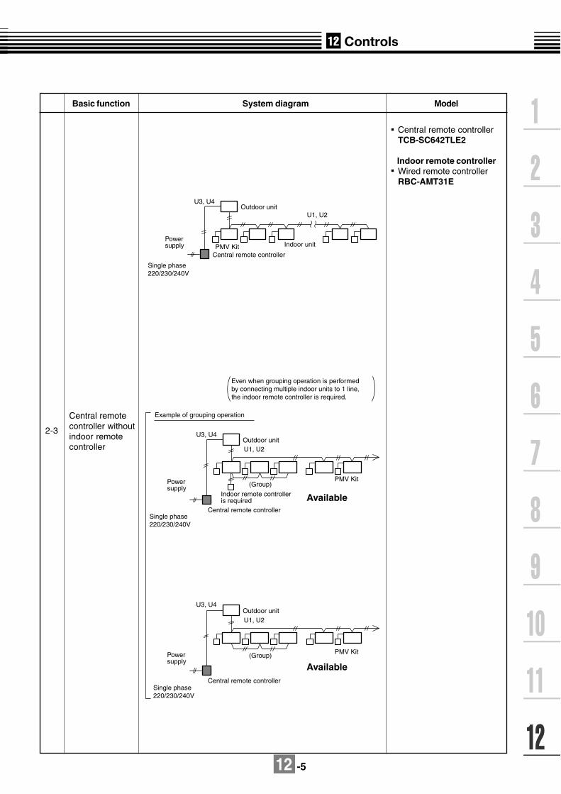
12 -5
Basic function System diagram Model
2-3
Central remotecontroller withoutindoor remotecontroller
Central remote controllerTCB-SC642TLE2
Indoor remote controllerWired remote controllerRBC-AMT31E
Outdoor unit
Single phase 220/230/240V
Powersupply
U3, U4
U1, U2
Central remote controller
Indoor unitPMV Kit
U3, U4
U1, U2
U1, U2
U3, U4
Single phase 220/230/240V
Powersupply
Single phase 220/230/240V
Powersupply
Outdoor unit
Available
Available
Central remote controller
Indoor remote controller is required
Outdoor unit
Central remote controller
(Group)
(Group)
Example of grouping operation
PMV Kit
PMV Kit
Even when grouping operation is performedby connecting multiple indoor units to 1 line,the indoor remote controller is required.

12 -6
Basic function System diagram Model
2-4
Central remote controllerTCB-SC642TLE2TCB-SC163TLE2
"1 : 1 model" connectioninterfaceTCB-PCNT30TLE2
RAV-SM560KRT-E,SM800KRT-E are notcompatible to connect
Indoor remote controller
Wired remote controllerRBC-AMT31E
Simple remote controllerRBC-AS21E2
* TOSHIBA Digital Inverter System and Super Digital Inverter System
Central manage-ment control with"1 : 1 model"
* 1
Powersupply
Outdoorunit
U1, U2
U3, U4
Central remote controller
Indoor remote controller
Indoor unit
"1:1 model"connection interface
PMV Kit

12 -7
12-1-3. Application control for network
Basic function System diagram Model
3-1 LONWORKS (*1)
LN interfaceTCB-IFLN640TLE
"1 : 1 model" connectioninterfaceTCB-PCNT30TLE2
RAV-SM560KRT-E,SM800KRT-E are notcompatible to connect
Indoor remote controllerWired remote controllerRBC-AMT31E
or
Simple remote controllerRBC-AS21E2
*1 TOSHIBA Digital Inverter System and Super Digital Inverter System
The LONWORKS interface should be connectedbetween a building management computer and aMini-SMMS / Super HRM / Super MMS system.
Max. 64 indoor units are connectable per interface.
TCB-LN Interface
Remote controller
LON Center
LON WORKS
* 1
"1:1 model"connection interface
PMV Kit
Outdoorunit
R
*1) LONWORKS : Registerd trademark Echelon corporation.
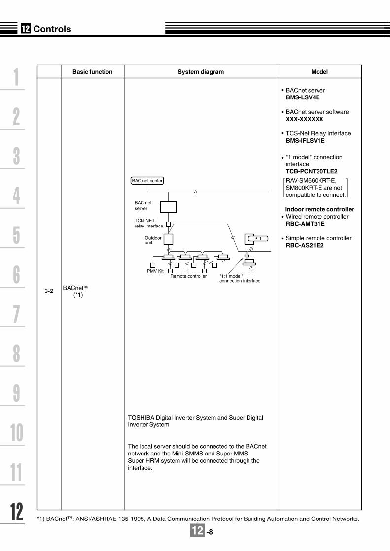
12 -8
BACnet serverBMS-LSV4E
BACnet server softwareXXX-XXXXXX
TCS-Net Relay InterfaceBMS-IFLSV1E
"1 model" connectioninterfaceTCB-PCNT30TLE2
RAV-SM560KRT-E,SM800KRT-E are notcompatible to connect.
Indoor remote controllerWired remote controllerRBC-AMT31E
Simple remote controllerRBC-AS21E2
Basic function System diagram Model
3-2 BACnet (*1)
*1) BACnetTM: ANSI/ASHRAE 135-1995, A Data Communication Protocol for Building Automation and Control Networks.
TOSHIBA Digital Inverter System and Super DigitalInverter System
The local server should be connected to the BACnetnetwork and the Mini-SMMS and Super MMSSuper HRM system will be connected through theinterface.
TCB-BAC net server
TCN-NETrelay interface
Remote controller
BAC net center
* 1
"1:1 model"connection interface
PMV Kit
Outdoorunit
R

12 -9
Model Name SpecificationBMS-TP0640ACE Max 64 indoor units , without energy monitoring and billingBMS-TP5120ACE Max 512 indoor units , without energy monitoring and billingBMS-TP0640PWE Max 64 indoor units , with energy monitoring and billingBMS-TP5120PWE Max 512 indoor units , with energy monitoring and billingBMS-LSV4E Server in between Touch Screen controller and RS-485BMS-STCC03E Installed on Intelligent ServerBMS-IFLSV1E Interface between intelligent Server Control wiring(TCC-LINK)BMS-IFWH3E Interface for power meterBMS-IFDD01E Interface for input / output signal
12-1-4. Touch screen controller systemSystem diagram
3-3
Dev
ices
Fun
ctio
n
Model NameTouch Screen controller(English version)
Intelligent ServerIntelligent Server SoftwareTCS-Net Relay InterfaceEnergy Monitoring Relay InterfaceDigital I/O Relay Interface(1) Monitoring air-conditioners
(2) Operating of air-conditioners
(3) Schedule operation
(4) Alarm list display
(5) Alarm record display
(6) Monthly report data extraction
(7) Energy monitoring data extraction
Header / individual control can be performed according to a unit.[Operating contents] ON/OFF, Operation setting (operation mode, air volume, louver position, setting temp., restricted setting from remote location)
Air-conditioners are operated according to the set-up schedule / operation pattern.Schedule opretaion can be performed according to a unit. [Operation pattern] Weekly pattern, special day pattern (4 pattern), Non-operation days pattern
The present alarm contents are displayed. [Display contents] Alarm contents, Unit number, Generated time
The alarm history records are displayed. [Display contents] Alarm contents, Unit number, Generated time
Monthly report data is written to "Compact Flash". Monthly reports can be created according toa unit using the monthly report software. [Monthly report contents] The number of ON/OFF, Operating time, Results of energy monitoring
Power consumption data is written to "Compact Flash". Energy monitoring can be performedaccording to a unit using the energy monitoring software. [Energy monitoring data] Power consumption according to the power meter
Operation status can be viewed according to a unit. [Unit] All building, All tenants, Each tenant, Each area, Each remote controller group [Monitoring contents] Operation and alarm status, Setting status for each remote controller group
Touch ScreenController
Maximum 4Intelligent server
Maximum 4 EnergyMonitoring
Relay Interface
Digital I/O Relay Interface
Maximum 4 Digital I/O Relay Interface
[ Power meter ]
Local supply1kWh/pulseor 10kWh/pulse50-1000ms
Intelligent Server SoftwareEthernetconnection
RS-485
Control Maximum 512 indoor units
Maximum 8 Power Meter
Fire alarmDoor Key Entry ON/OFFError code output
Pulse SignalI/F
Intelligent Server
Control wiring
Control wiring
Control wiring
I/F
Max. 64indoor unitsMax. 16Refrigerantsystemsper TCS-NET relayinterface
TCS-Net Relay Interface
Energy Meter Relay Interface
Maximum 8 TCS-NET Relay Interface
Switching HUB
(Local Supply)
PC for Energy
Monitoring
(Local supply)
RS-485
RS-485
RS-485
(Note)Switching HUB (10BASE-T compliant) is requiredwhen using two or more intelligent servers or whenconnecting a PC for energy monitoring and billing.
Maximum 8 digital inputs
Maximum 4 digital outputs
Report Creation
software
(Excel macro)
Max. 32 (8 X 4)power meterper intelligentserver
Max. 32 (8 X 4)digital inputsMax. 16 (4 X 4)digital outputsper intelligentserver
Setup file(record in CF card)
(Revised 19 May 2006)

12 -10
80 120
6070
13
16
RBC-AMT31E
120
62
8418
16
120
12-2. Controller dimensions
Note : All dimensions are in mm
Note : All dimensions are in mm
Simple remote controller
Wired remote controller
RBC-AS21E2

12 -11
Wireless remote controller kit
RBC-AX22CE2
18658 19.5
61
186
177
32
TCB-AX21U (W)-E2
58 19.5130
61
177
65
Note : All dimensions are in mm
Note : All dimensions are in mm

12 -12
TCB-AX21E2
Wireless remote controller kit
RBC-EXW21E2
Weekly timer
13
83.5
83.5
70 4.4 x 5.4 long hole
4.4 x 9.4 long hole
58 19.5
61
177
16120
4
2.7
120
Note : All dimensions are in mm
Note : All dimensions are in mm

12 -13
ON-OFF controller
116
160
1486 (6)
122
160
148
6(6
)
12
1
11
5
6914
128
80
128 80
36 47
13
Unit: mm
Z
4-Ø5 diameter holes(for mounting)
Hole for electrical wiring
4-Ø5.5 diameter holes (for mounting)
Z-view (back side)
TCB-CC163TLE2
Note : All dimensions are in mm

12 -14
Remote sensor
Central remote controller
80 120
6070
13
16
TCB-TC21LE2
TCB-SC642TLE211647
15
13
1601486 (6)
121
160
148
6(6
)
121
115
6921
12880
128
80
36
47
13
Z
Z view (back side)
Note : All dimensions are in mm
Note : All dimensions are in mm

12 -15
200
22787822
22787822
66
63.6
146.
9
156
170
6- 5.5 mounting holes
BMS-IFLSV1E
TCS-Net relay interface
BMS-TP0640ACEBMS-TP5120ACEBMS-TP0640PWEBMS-TP5120PWE
Touch screen controller
70
25695
.75
91.7
575
75
316249
48
1624
299
.3
82.5 30255.5
3019
54495
Note : All dimensions are in mm
Note : All dimensions are in mm

12 -16
234
1818
(193
)92
.564
.5
1818
53.5
103.
5
63.6
220
246
Grommet forpower input
Grommet forpower meter
Grommet forRS-485
BMS-LSV2E
Intelligent server
BMS-IFWH3EBMS-IFDD01E
Energy monitoring relay interface/Digital I/O relay interface
370
198
39CAUTION
Do not rem
ove.
WARNINGDo not decompose.
Note : All dimensions are in mm
Note : All dimensions are in mm
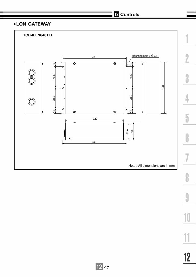
12 -17
TCB-IFLN640TLE
LON GATEWAY
Note : All dimensions are in mm
234
18
193
18
1818
78.5
78.5
78.5
78.5
63.6
66
220
246
Mounting hole 6-O/ 5.5


