

Filling the VoID
in VoIP TestingAn White Paper
760 Arrow Grand Circle ¥ Covina, CA 91722 ¥ 626 915 5441 ¥ www.ameritec.com
©2000 Ameritec Corporation
___________________________________________________________________________________________________________________________________________________________________________________________________________________________________________________________________________________________________________________________________________________________________________________________________________________________________________
: Filling the VoID in VoIP Testing 1
Filling the VoID in VoIP Testing
With the telecommunications industryÕs quick move to adopt Perceptual Speech Quality
Measurement (PSQM) as the ÒstandardÓ for voice quality testing of VoP networks and systems, a
testing void was created due to a possible lack of understanding of PSQMÕs intent and limitations.
Although it is potentially useful, it is evident that PSQM does not completely characterize those
factors which contribute to poor voice quality. As indicated in the following excerpts, VoP
developers and network operators need more data than PSQM can provide to characterize their
systems.
The following excepts are taken from the article ÒMeasuring Voice Quality: Listening by the
NumbersÓ by David Willis, in the May 1999 issue of Network Computing:
ÒItÕs WhatÕs Inside That Counts As flawed as they are, automated measurements such as
PSQM fill a real needÑbut itÕs not in external test equipment. Instead, we need embedded, real-
time performance measurement inside next-generation voice-over-packet products. Imagine an
RMON standard for voice services, with internal probes generating PSQM-like scores between
critical points in the network and issuing alerts when the quality falls below a service-level
threshold. The alerts might trigger an automatic failover to the circuit-switched network.Ó
ÒYet PSQM isnÕt a complete solution for use in voice-over-packet networks. By the authorÕs own
admissionÓ (KPN Research Holland), ÒP.861Õs approach doesnÕt account for several key factors
that may critically affect perception Ðsuch as cell and packet loss, the clipping effect of bad
voice-activity-detection mechanisms or the impact of bit errors. These problems are commonly
found in voice-over-frame relay, ATM, and IP networks.Ó
ÒRecognizing the failure of the ITU-T specs, Ameritec has taken a radically different approach
with its Voice Over Packet application test suite on its existing (and highly useful) call
generators. The software measures dropouts, round-trip delay, and signaling errors, in addition to
its normal call-loading capabilities.Ó ÒÉ it tends to produce quantifiable, reproducible, and
comparable output.Ó
Ameritec has realized and examined this need and has created a test suite that fills this void in
VoP testing by providing delay, jitter, clipping, and dropout (packet loss) measurement
capabilities.
___________________________________________________________________________________________________________________________________________________________________________________________________________________________________________________________________________________________________________________________________________________________________________________________________________________________________________
: Filling the VoID in VoIP Testing 2
Quantitative Analysis for Voice over Packet Testing Ð The Ameritec Solution
Introduction
Voice over Packet (VoP) network testing should be concerned with the three QÕs:
• Voice Quality
• Conversation Quality
• Service Quality
The first part of this paper covers Voice, Conversation, and Service Quality issues. Voice and
Conversation quality covers latency, jitter, dropouts, and clipping. Service Quality includes a brief
introduction to RSVP, DiffServ and MPLS protocols, of which, the latter two protocols will likely become
the main protocols found in future Quality of Service (QoS) domains. The last portion of the paper covers
network testing, problem identification, fault isolation, and network optimization techniques.
VoP network testing differs from standard packet network testing in that packet networks were not
originally designed for time-sensitive real-time voice applications. Lower bit-rate codecs and non-linear
compression techniques used in packet networks degrade the quality of the source signal. While codecs
can be measured using artificial qualitative testing techniques such as the PSQM or Perceptual
Analysis/Measurement System (PAMS), component delays and group delay variances that have a negative
effect on the ebb and flow of a conversation can only be truly measured quantitatively. Lost packets, out-
of-sequence packets, and signal clipping affect signal clarity and are more easily detected using quantitative
measuring techniques.
Quantitative measurements make it easier to identify specific network components or network paths that
need optimization or replacement because quantitative measurements are category specific, can be
reproduced, and can be used for comparisons with previous measurements. Impairments that affect
qualitative results, such as lost packets, jitter, or noise, cannot be isolated in mean scoring approaches. A
low score simply indicates that something is bad. Was the problem caused by lost packets, quantizing
noise, circuit noise, or jitter? Qualitative scoring, which ignores delays, may identify a problem but offers
no solution. While qualitative and quantitative measurements are both artificial means of substituting for
the human element, qualitative measurements do not isolate factors that may cause a low score.
Voice testing of packet networks should be concerned with both the clarity of the reproduced voice signal
and the rhythm of the conversation, as well as service issues related to guaranteed performance and call
setup and teardown. While clarity may be tested using qualitative methods, it does not test the rhythm and
feel of the conversation and is not suited for fault isolation. The ability to quantize timed results to within 5
msec, to monitor the complete conversation, and to generate multiple calls with realistic traffic profiles, are
the reasons Ameritec has chosen quantitative testing techniques to set the VoP network testing standards.
The next few paragraphs demonstrate the strengths and weaknesses of purely qualitative voice
measurements for Voice over Packet Testing on complete networks. The PSQM algorithm is used as an
example.
___________________________________________________________________________________________________________________________________________________________________________________________________________________________________________________________________________________________________________________________________________________________________________________________________________________________________________
: Filling the VoID in VoIP Testing 3
Voice and Conversational Quality
Qualitative Scoring using PSQM: Delays and Jitter and their effect on Scoring
PSQM, defined in ITU-T P.861, is an algorithm primarily designed for evaluating and optimizing codecs
by comparing a preconditioned source signal with a coded output signal. The audio input is preconditioned
per ITU-T P.830 to simulate how a human voice would sound speaking into a telephone handset. ITU-T
P.50 defines the characteristics and phrases to be used in the source signal. The algorithm measures voice
quality as it would be perceived at the human ear and is based on the Mean Objective Score (MOS). The
MOS is a subjective measurement, defined in ITU-T P.800, that uses live participants to rate voice quality.
MOS scoring is scaled from 1 to 5, with five being best; while PSQM scoring is scaled from 0 to 6.5, with
0 being best.
The PSQM algorithm is time alignment sensitive, that is, the algorithm compensates for latency by
subtracting the known delay from the delayed samples. If the delay is not known, the delay can be raised
by trial and error to find the delay that results in the best PSQM score.
The PSQM algorithm is best suited to measuring the effects of digital distortions caused by non-linear
voice compressions, quantizing noise, transcoding errors, and random bursty errors such as packet loss.
Today, however, PSQM testing is not limited to evaluating and optimizing codecs. PSQM is being used to
check the one-way listening-only voice quality of complete networks that may even include PSTN tail
circuits. Packet networks, however, were not designed for time-sensitive real-time voice applications.
Network delays that degrade conversation quality are common, but due to the PSQM time alignment
techniques, these delays do not affect scoring. Secondary effects of delays, however, may affect scoring.
Examples of secondary effects are:
• delays that cause uncancelled Public Switched Telephone Network (PSTN) echo components to be
noticeable, such as those caused by doubletalk or borderline return loss noise hovering around the
normally acceptable -30 dBm level.
• congestion delays that manifest themselves as lost or out-of-sequence packets.
DELAYS
Latency and delay variations (jitter) are factored out of the PSQM algorithm and have a major effect on
listening quality of actual human ears, thus limiting PSQMÕs ability to adequately test a network or
complete system. Delays that cause a conversation to have gaps or sound choppy have little or no effect on
PSQM scores. This phenomenon proved itself during Ameritec field testing of IP networks with long
delays. In fact, the PSQM algorithm did its job; it compensated for the delays very well, giving the
impression that the perceived voice quality was better than it really was.
One-way delays greater than 150 msec begin to cause the listener to subconsciously hesitate before
responding; the greater the delay, the longer the hesitation. This makes the mood of the conversation sound
cold. Response hesitations may become more pronounced if the delays cause an echo component to be
introduced into the conversation. Different path delays through a network may cause individuals to
interrupt one another (doubletalk). Echo cancellers often have trouble compensating for this doubletalk.
___________________________________________________________________________________________________________________________________________________________________________________________________________________________________________________________________________________________________________________________________________________________________________________________________________________________________________
: Filling the VoID in VoIP Testing 4
Delays greater than 400 msec may result in lost or out-of-sequence packets, which, like echo, affect both
the sound reproduction and the conversation flow. Often in conversations, small return utterances that
acknowledge a point are expected. If these utterances occur at the wrong time or are dropped, confusion
results. Acknowledgement examples in English, are mm hmm, yes, OK, etc.; in Japanese, Hai; in Chinese,
Dui; etc. These acknowledgements are short but necessary elements in many conversations.
Typical Delays
The following list describes the various entities that add delays in a VoP or VoIP network.
PSTN: PSTN delays are typically 30 msec and ÔseldomÕ more than 150 msec (G.114). Delays from a
wireless network, however, may be higher, and, if a satellite is in the loop, the one-way delays can add an
additional 250 msec.
Internet Delays: Internet delays are totally unpredictable and are based on best-effort routing. Delays of 50
msec to 400 msec are typical. Delays greater than 400 msec with high dropout rates are not, however,
unusual.
Packet Network: Delays in packet networks occur as a result of quantizing, buffering, queuing, switching,
and routing. Propagation delays are very short and have little effect. The following is a list of typical
areas where delays occur in a Packet Network listed either by function or device:
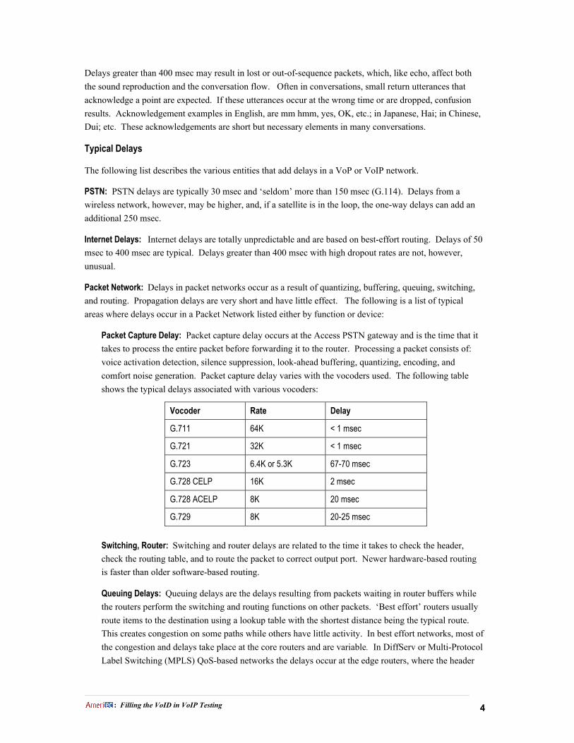
Packet Capture Delay: Packet capture delay occurs at the Access PSTN gateway and is the time that it
takes to process the entire packet before forwarding it to the router. Processing a packet consists of:
voice activation detection, silence suppression, look-ahead buffering, quantizing, encoding, and
comfort noise generation. Packet capture delay varies with the vocoders used. The following table
shows the typical delays associated with various vocoders:
Vocoder Rate Delay
G.711 64K < 1 msec
G.721 32K < 1 msec
G.723 6.4K or 5.3K 67-70 msec
G.728 CELP 16K 2 msec
G.728 ACELP 8K 20 msec
G.729 8K 20-25 msec
Switching, Router: Switching and router delays are related to the time it takes to check the header,
check the routing table, and to route the packet to correct output port. Newer hardware-based routing
is faster than older software-based routing.
Queuing Delays: Queuing delays are the delays resulting from packets waiting in router buffers while
the routers perform the switching and routing functions on other packets. ÔBest effortÕ routers usually
route items to the destination using a lookup table with the shortest distance being the typical route.
This creates congestion on some paths while others have little activity. In best effort networks, most of
the congestion and delays take place at the core routers and are variable. In DiffServ or Multi-Protocol
Label Switching (MPLS) QoS-based networks the delays occur at the edge routers, where the header

___________________________________________________________________________________________________________________________________________________________________________________________________________________________________________________________________________________________________________________________________________________________________________________________________________________________________________
: Filling the VoID in VoIP Testing 5
setup or labeling takes place. These delays are usually 20-30 msec in duration. Using these protocols,
the individual core router delays are reduced to approximately 5 msec each.
In QoS networks, path management protocols such as MPLS should optimize throughput. By virtue of
using multiple paths, however, these protocols can introduce jitter.
Jitter Buffers: Jitter buffers at the egress or exiting Gateways have delays that range from 0 (off) to
255 msec (maximum). Some jitter buffers are self optimizing while others can be optimized by the
network administrator. In networks whose total delays are less than 100 msec, jitter buffers can be set
as low as 20 to 40 msec. Networks with longer delays need larger buffers settings. Ameritec Call
Generators, that measure delays and jitter to within 5 msec, can be used both to optimize buffer sizes
and to verify the effectiveness of path management protocols.
Miscellaneous Delays: Equipment such as Standalone Firewalls and Proxy Servers can also add
upwards of 150 msec of delay to the network because they must receive, decode, examine, validate,
encode, and transmit every packet.
Packet Length: Optimizing packet lengths, like optimizing buffer size, involve tradeoffs. Generally,
shorter packets create less processing delays at router buffers and egress gateways. A higher
proportion of packet size, however, is dedicated to header information, thereby lowering the effective
bandwidth of the network.
The following table summarizes typical delays in an uncongested network:
Device / Function Typical Delay
Access Gateway (incoming line speed dependent) 0-8 msec
Compression / Coding (vocoder type dependent) 0-70 msec
Interprocess Delays (between coding & queuing) 10 msec
Best Effort Routers (no congestion) 20-25 msec each
DiffServ or MPLS Edge Routers 20-30 msec
DiffServ or MPLS Core Routers 5 msec each
Jitter Buffers at Egress Gateways 10 Ð 80 msec
Decompression / Decoding < 10 msec
Egress Gateway (outgoing line speed dependent) 0-8 msec
Relieving Network Congestion: Sound Suppression and Comfort Noise
Most voice conversations are half-duplex in nature. One person is usually listening, while the other is
talking. To reduce network congestion, itÕs only necessary to send packets when someone is talking.
Between listening and normal conversation lulls, voice traffic can be reduced in half by not sending packets
during this quiet time. This is accomplished by Voice Activation Detectors (VAD) at network gateways.
When voice is detected, the gateway sends packets; when it stops, the gateway stops sending packets
(silence suppression).
___________________________________________________________________________________________________________________________________________________________________________________________________________________________________________________________________________________________________________________________________________________________________________________________________________________________________________
: Filling the VoID in VoIP Testing 6
When the packets are reassembled on the other end, the quiet time is replaced by a comfortable noise level
generated by a Comfort Noise Generator (CNG) in the outgoing gateway. Comfort noise is generated to
prevent the absence of sound from being perceived as a disconnect. Using sampling techniques, newer
CNGs try to emulate the actual background noise in both level and frequency.
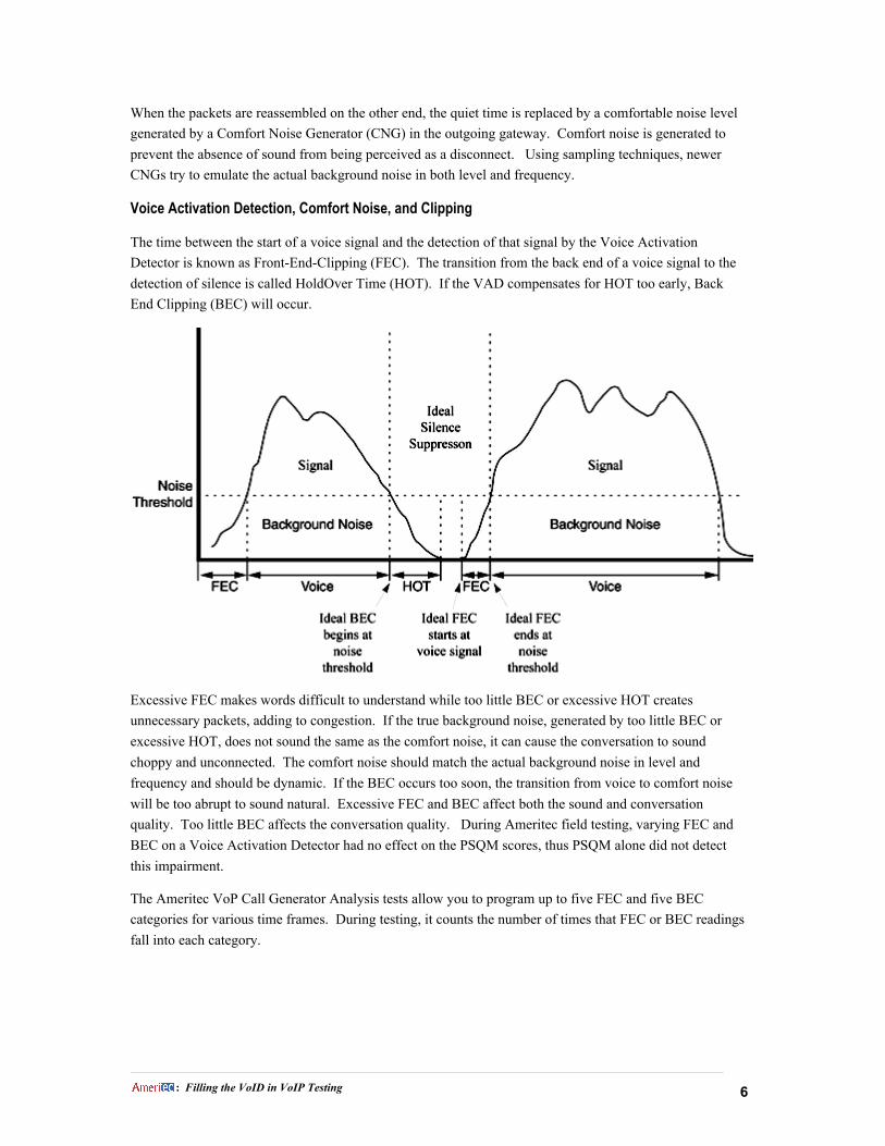
Voice Activation Detection, Comfort Noise, and Clipping
The time between the start of a voice signal and the detection of that signal by the Voice Activation
Detector is known as Front-End-Clipping (FEC). The transition from the back end of a voice signal to the
detection of silence is called HoldOver Time (HOT). If the VAD compensates for HOT too early, Back
End Clipping (BEC) will occur.
Excessive FEC makes words difficult to understand while too little BEC or excessive HOT creates
unnecessary packets, adding to congestion. If the true background noise, generated by too little BEC or
excessive HOT, does not sound the same as the comfort noise, it can cause the conversation to sound
choppy and unconnected. The comfort noise should match the actual background noise in level and
frequency and should be dynamic. If the BEC occurs too soon, the transition from voice to comfort noise
will be too abrupt to sound natural. Excessive FEC and BEC affect both the sound and conversation
quality. Too little BEC affects the conversation quality. During Ameritec field testing, varying FEC and
BEC on a Voice Activation Detector had no effect on the PSQM scores, thus PSQM alone did not detect
this impairment.
The Ameritec VoP Call Generator Analysis tests allow you to program up to five FEC and five BEC
categories for various time frames. During testing, it counts the number of times that FEC or BEC readings
fall into each category.
___________________________________________________________________________________________________________________________________________________________________________________________________________________________________________________________________________________________________________________________________________________________________________________________________________________________________________
: Filling the VoID in VoIP Testing 7
Dropped Packets
Since voice packets are time sensitive, there is only a narrow window of time to resequence and align the
packets into intelligible speech. Dropped or lost packets which may be caused by congestion, delays, or
error retransmissions may cause holes in the conversation or cause a conversation to be garbled. Individual
packet losses may have an annoying effect on the conversation while bursty losses can be quite intolerable.
The conversation effect varies with the vocoders used. A single packet loss has a greater effect when low-
bit rate vocoders are used than it would if a G.711 codec was used.
Note: Some G.711 codecs compensate for packet loss using a Packet Loss Compensation (PLC) algorithm.
PLC samples the speech before and after the loss and tries to fill in the gap. Lower rate vocoders do
not have this capability.
Packet size also has a direct effect on speech quality. Larger packets decrease network congestion because
the overall header-to-content ratio is smaller. However, when a large packet is lost, it causes a more
noticeable gap in the speech element. Larger packets also require more buffer space, adding to delays.
The percentage of overhead associated with narrower packets, however, has an adverse effect, in that it can
increase circuit congestion, thus offsetting the benefits of shorter delays and increased fidelity.
PSQM scoring does not weight packet loss sufficiently. Individual packet losses as high as 5% have little
effect on the scoring. A 5% packet loss can sound choppy and, if bursty in nature, can be very irritating.
Ideally, packet loss should be < 1%, with 3% acceptable. A modified algorithm, PSQM+, has been created
that places a more realistic weighting on lost packets.
Better yet, Ameritec Call Generators measure voice dropouts as small as 5msec. This lost voice is a direct
result of lost packets. Each voice dropout is sorted into one of five statistical bins in accordance with its
time duration. The bins are programmable and can be set to record single and multiple packet losses that
can be based on the length of a typical packet. Network buffers, in particular, Jitter Buffers, can be
optimized using the FeatureCall Test Case Traffic Profiler to accurately profile network traffic and to
monitor both the dropped packets and jitter. Optimization is accomplished by comparing the results before
and after buffer adjustment. The Traffic Profiler can also be used to verify that buffers, which
automatically adjust for traffic, are working properly by varying the profiles used.
___________________________________________________________________________________________________________________________________________________________________________________________________________________________________________________________________________________________________________________________________________________________________________________________________________________________________________
: Filling the VoID in VoIP Testing 8
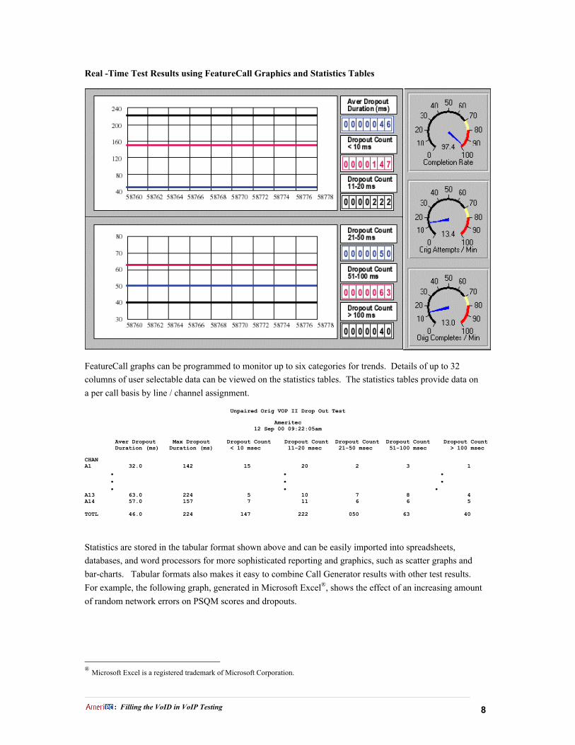
Real -Time Test Results using FeatureCall Graphics and Statistics Tables
FeatureCall graphs can be programmed to monitor up to six categories for trends. Details of up to 32
columns of user selectable data can be viewed on the statistics tables. The statistics tables provide data on
a per call basis by line / channel assignment.
Unpaired Orig VOP II Drop Out Test
Ameritec12 Sep 00 09:22:05am
Aver Dropout Max Dropout Dropout Count Dropout Count Dropout Count Dropout Count Dropout Count Duration (ms) Duration (ms) < 10 msec 11-20 msec 21-50 msec 51-100 msec > 100 msec
CHANA1 32.0 142 15 20 2 3 1 . . . . . . . . .A13 63.0 224 5 10 7 8 4A14 57.0 157 7 11 6 6 5
TOTL 46.0 224 147 222 050 63 40
Statistics are stored in the tabular format shown above and can be easily imported into spreadsheets,
databases, and word processors for more sophisticated reporting and graphics, such as scatter graphs and
bar-charts. Tabular formats also makes it easy to combine Call Generator results with other test results.
For example, the following graph, generated in Microsoft Excel¨, shows the effect of an increasing amount
of random network errors on PSQM scores and dropouts.
¨ Microsoft Excel is a registered trademark of Microsoft Corporation.

___________________________________________________________________________________________________________________________________________________________________________________________________________________________________________________________________________________________________________________________________________________________________________________________________________________________________________
: Filling the VoID in VoIP Testing 9
Signal Level
Another factor that affects the perceived quality of speech is the level of loudness and fading. Many signal
level problems can be traced to PSTN or wireless tail circuits, however, the multiplicity of carriers and
equipment vendors that supply A/D converters, low bit-rate codecs, voice-activity-detectors, echo
cancellers, and fax modems are impacting the voice levels. Newer equipment built to ITU-T G.169
recommendations should minimize this problem in the future.
Service QualityIdentifying Voice Packets
In open networks, itÕs very difficult to distinguish between voice and data packets. In fact, legacy frame
relay networks have no service type headers and many IP or ATM network gateways do not identify the
service type and will not prioritize voice packets. Protocols designed to alleviate this weakness are not
widely implemented and may be incompatible with older gateways.
With more users and businesses going online everyday, coupled with the demand for more and better
multimedia service, Internet traffic is doubling three times a year. This phenomenon increases the need for
more bandwidth. Congestion in public networks, especially at peak periods, will be a problem for some
time to come. In the meantime, the industry must learn to make the best use of whatÕs available, by
delivering high-priority voice traffic with fidelity, low latency, and few dropouts. Some routers can be
programmed to identify voice/fax calls by looking for the gateways ÔUDP port numberÕ and give these
packets higher priority. Most of the near term improvements in VoP quality will come in private networks
using VoFR, VoIP, or VoATM because delays can be controlled and newer QoS protocols can be
consistently applied. Bandwidth can also be increased incrementally as the need increases. Voice over the
Internet, on the other hand, will have quality problems for a long time to come.

___________________________________________________________________________________________________________________________________________________________________________________________________________________________________________________________________________________________________________________________________________________________________________________________________________________________________________
: Filling the VoID in VoIP Testing 10
Quality of Service Protocols, An Introduction
Quality of Service (QoS) protocols basically are sets of rules that tell a network how to identify and route
individual packets or groups of packets based on class of service requirements. Protocols exist at various
OSI layers, often allowing more than one set of rules to operate simultaneously. For the purpose of this
paper, we are going to ignore gateway control protocols and concentrate on QoS related protocols.
Quality of Service protocols must provide a measure of predictability and control above and beyond the
Ôbest effortÕ methods used by the legacy Ethernet, legacy Frame Relay networks, and the Internet. There
are four basic approaches to achieving the goals of service predictability and control.
• bandwidth allocation • path management
• class prioritization • flow control and queue management
QoS protocols use one or more of these techniques in varying degrees of complexity to achieve their goals.
The following is a brief description of each technique:
Bandwidth Allocation: Allots specific amounts of bandwidth for different traffic types.
Class Prioritization: Assigns specific priorities to various service classes with drop precedences for
dropping packets during times of congestion. Priorities are enforced by aggregate bandwidth allocation or
on a Ôpacket-by-packetÕ basis.
Path Management: ÔBest effortÕ routers usually route items to the destination using a lookup table with
the shortest distance being the typical route regardless of traffic on that path. Path management techniques
attempt to optimize path flow through the network so that all paths through the network core have a similar
amount of traffic.
Flow Control and Queuing Management: A method of scaling back the network traffic so that the
network doesnÕt become congested by limiting ingress traffic and buffering egress traffic as needed to
maintain acceptable delays, jitter, and flow rate. Queuing Management is an often-used subset of Flow
Control. Queue management occurs in core routers and consists of reviewing packet markers and
establishing multiple priority queues. Two commonly accepted methods of queuing management are
Weighted Random Early Detection (WRED) and Weighted Fair Queuing (WFQ).
Introduction to RSVP, DiffServ, and MPLS
Generally, QoS protocols such as Resource Reservation Protocol (RSVP), Multi-Protocol Label Switching
(MPLS), and DiffServ (DS) will need to be incorporated, must be interoperable, and interact at domain
boundaries. The next few paragraphs provide an overview of three QoS protocols: RSVP, MPLS, and DS.
The former, RSVP, has many current installations but is extremely complex and has a lot of overhead.
MPLS and DS, because of their simplicity and interoperability are or will be implemented in many of the
newer routers. RSVP is also strictly a network protocol, whereas MPLS and DS are an intergral part of the
data transfer.
RSVP: RSVP protocols, such as Integrated Services (IntServ) operate in similar fashion to ATM QoS, that
is, they allocate bandwidth based on perceived requirements. RSVP does not carry data. RSVP is a
___________________________________________________________________________________________________________________________________________________________________________________________________________________________________________________________________________________________________________________________________________________________________________________________________________________________________________
: Filling the VoID in VoIP Testing 11
network protocol, designed to setup and teardown a call and works in parallel with data flow protocols such
as UDP or TCP. RSVP operates by receiving service requests and then establishing and reserving a
guaranteed path for that request. The request contains information such as minimum and maximum
bandwidth, delay, and jitter requirements. RSVP sends out reservation requests to the first router in the
proposed path. If the router can meet the requirements, it passes that request forward to the next router in
the path until a virtual circuit is established or until a router returns an error message indicating the
resources are not available. Once all the routers have accepted the request, the path is either guaranteed for
the duration of the data transfer or call (highest priority) or the router will attempt to provide the service
and maintain the circuit as long as the network is uncongested.
The main drawbacks to RSVP are its complexity and overhead. It has to allocate a guaranteed bandwidth
based on a range and has long setup and teardown times. During the transfer, the reservations must be
periodically updated. If the parameters cannot be met, the call or transfer cannot take place. Once a call /
transfer is completed by the sender or receiver, RSVP must also teardown the call, so that the resources can
be reallocated.
Differentiated Services (DiffServ or DS): DS relies on prioritizing, policing, and managing techniques. DS
classifies traffic by marking packets with service level indicators using the first six bits of the IP Type of
Service (ToS) header. These six bits are known as the DiffServ Code Points (DSCP). Routing decisions
are made on a per packet basis rather than a per session basis. DS enforces service agreements between
domains, manages traffic by dropping traffic when necessary and, when implemented, uses shaping polices
to smooth out bursty transmissions. The major keys to the DS protocol model are the Class of Service
(CoS) levels, the Ôper hopÕ behavior method of routing, and queuing management mechanisms in the core
routers.
The Ôper hopÕ method of routing is on a packet-by-packet basis at each router, thus eliminating bandwidth
allocation and simplifying the work of core routers. The DS edge routers handle the overhead associated
with traffic conditioning. This allows core routers, where most of the congestion occurs, to simplify their
processes based on the negotiated service level rating in the DSCP header and queue management.
DS has three basic Ôper hopÕ service levels. The service levels in order of priority are Expedited
Forwarding, Assured Service, and Best Effort. Contracted services use Expedited Forwarding and Assured
Service. Expedited Forwarding guarantees bandwidth, while Assured Service allocates four classes of
bandwidth. Each Assured Service bandwidth class has three drop precedences. Best effort uses whatever
bandwidth remains after contracted services have used their allotment and are the first to be dropped.
DS uses both WRED and WFQ Queue management in the core routers. WRED randomly discards packets
in a TCP network that is starting to become congested. This process causes the TCP to slow down the
traffic rate. Since WRED is weighted, higher priority traffic is protected.
WFQ gives higher preference to low volume traffic. This prevents high-volume traffic from consuming
large chunks of bandwidth and over shadowing the low-volume traffic. WFQ only operates on packets of
equal priority, that is high-priority large bandwidth packets would still have priority over low-volume low-
priority data.
MPLS: MPLS relies on path determination and flow manipulation. MPLS, which resides between Layer 2
and Layer 3, attaches a 20-bit label to each packet at the ingress boundaries of the network and removes it
at the egress boundary. The 20-bit label includes a 3-bit CoS field. MPLS routes the labeled packets
___________________________________________________________________________________________________________________________________________________________________________________________________________________________________________________________________________________________________________________________________________________________________________________________________________________________________________
: Filling the VoID in VoIP Testing 12
across the least congested portions of the network rather than across the shortest distance. MPLS thereby
optimizes the use of each network path, maximizing throughput and response times. MPLS operates by
attaching routing labels to each packet at the access routers and forwarding the packet to the next router.
The receiving router updates the routing label based on lookup tables and forwards the packet to the next
router. This process continues until the packet reaches the egress router, where the labeling is stripped.
MPLS also supports tunneling techniques. Tunneling allows the ingress router to define the complete path
through the network similar to RSVP. MPLS labeling does not interfere with other protocols, such as DS,
allowing networks to simultaneously employ multiple QoS techniques.
VoIP, VoFR, and VoATM Interoperability
Work is being performed by the Frame Relay Forum vendors to incorporate QoS techniques for Voice over
Frame Relay as well as interoperability. Connection-oriented ATM already has QoS capabilities built in.
ATM work is being done in the area of interoperability with IP QoS protocols. Until interoperability with
networks as well as Application Programming Interfaces (APIs) are defined and incorporated across the
board, QoS problems will continue when crossing network boundaries, causing high-priority packets to
revert to Ôbest effortÕ behavior. Testing needs to occur both within a network and across various domains
to assure VoP acceptance. For the near term, successful implementations may be limited to Private Virtual
Networks where bandwidth, delays, and QoS mechanisms can be controlled.
Guaranteeing Service Levels
Since congestion will be a problem for some time, and the increase in voice calls continues, the need for
better network management continues to grow. At first glance, it would seem that as the new protocols
evolve and become an inherent part of networks, that QoS would improve and, with improvement, that
there would be a decreased need for extensive testing.
The QoS evolution, however, will increase the need for testing. Very simply, a service provider guarantees
and bills for a class of service, and thus must have a means of verifying that that quality of service can be
delivered or customers can be lost. A good example of this phenomenon is the ÔchurnÕ or customer
turnover experienced by the wireless industry. The question is, then, how can a service provider verify that
its customers are getting the quality for which they are paying? How can they identify a problem before the
customer sees it?
The easiest way to ascertain that high priority packets are getting through is to originate and terminate
multiple VoP calls at various gateway locations throughout the network and record the results.
QoS Problem Identification and Isolation
Using AmeritecÕs GPS synchronized bulk call generator with the VoP Test Suite is an excellent way to
verify that high priority DS VoIP calls are getting through with a minimal amount of latency and dropouts.
You can check the balancing of MPLS networks by comparing the simultaneous results of different calls
being made on different network paths. If the average delays and dropouts vary greatly from call-to-call,
___________________________________________________________________________________________________________________________________________________________________________________________________________________________________________________________________________________________________________________________________________________________________________________________________________________________________________
: Filling the VoID in VoIP Testing 13
then the edge routers are not maximizing the throughput by balancing the network paths. Additionally,
Analysis Tests that measure dropouts also measure jitter and front- and back-end clipping (FEC & BEC).
If FEC or BEC is too short, extra packets are sent. If FEC or BEC is too long, or if unacceptable jitter
occurs, the voice and conversational quality degrades.
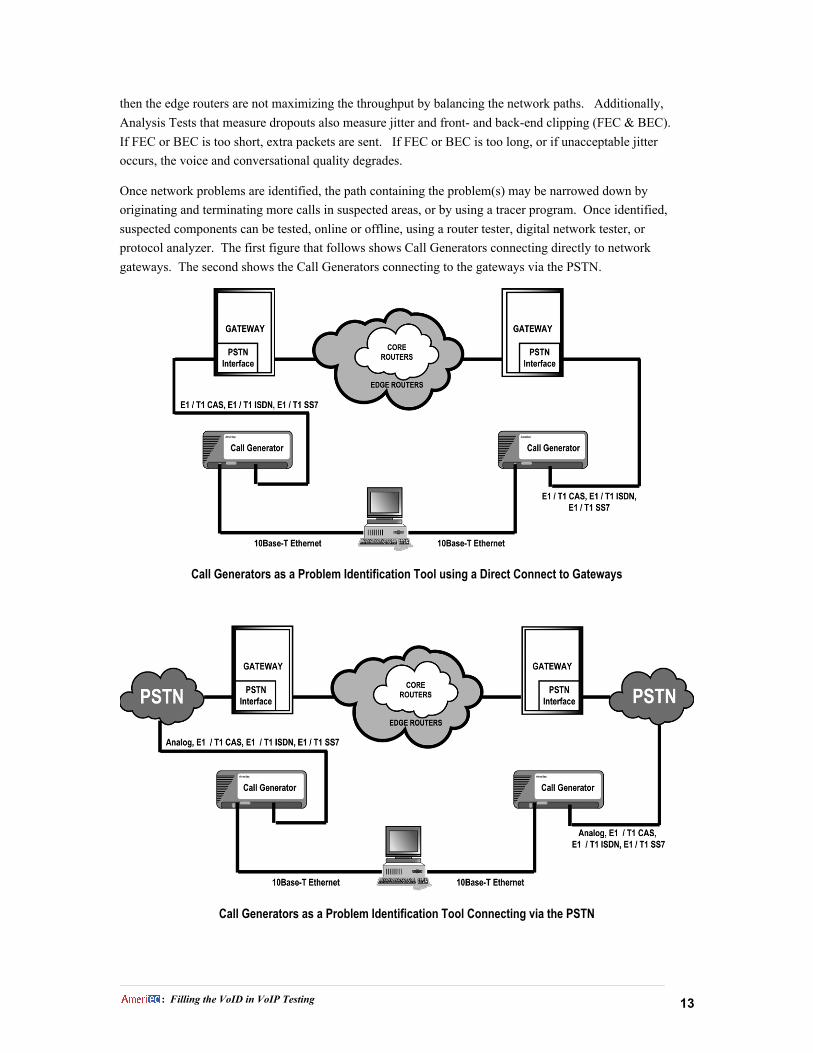
Once network problems are identified, the path containing the problem(s) may be narrowed down by
originating and terminating more calls in suspected areas, or by using a tracer program. Once identified,
suspected components can be tested, online or offline, using a router tester, digital network tester, or
protocol analyzer. The first figure that follows shows Call Generators connecting directly to network
gateways. The second shows the Call Generators connecting to the gateways via the PSTN.
Call Generators as a Problem Identification Tool using a Direct Connect to Gateways
Call Generators as a Problem Identification Tool Connecting via the PSTN

___________________________________________________________________________________________________________________________________________________________________________________________________________________________________________________________________________________________________________________________________________________________________________________________________________________________________________
: Filling the VoID in VoIP Testing 14
Fault Isolation and Network Optimization
The following paragraphs list the Ameritec field tests and the quantized data collected by each test. Not
only can categorical results be used to help determine the health of a network, they can also assist in
isolating impaired equipment or network paths that are causing problems.
The following graphics show some of the user-friendly tools available for modifying the reporting
capabilities to meet dynamic testing requirements. The bin parameters and titles shown in the examples
below can be easily changed using the FeatureCallª Call Program setup and the ScriptMate¨ Define Report
Format windows. The Select Data Set windows are used to select up to six presentation categories for
FeatureCall Graphs.

___________________________________________________________________________________________________________________________________________________________________________________________________________________________________________________________________________________________________________________________________________________________________________________________________________________________________________
: Filling the VoID in VoIP Testing 15
One-Way or Round-Trip Delay Tests
One-Way Delay Tests measure single direction (half-duplex) delays. The originate side of the call either
sends or receives a pulse from the terminate side. This flexibility allows measurements to be made in either
direction. Round-Trip delays measure the full duplex delay. It measures the time it takes a pulse to travel
from the terminate side of the call to the originate side and then back to the terminate side.
The graphs can be a useful tool in determining the ranges where most of the delays are occurring. The
above graph represents a network test at maximum call rates showing an average delay of 98 msec. Based
on the above results, another set of call programs can be run with more narrowly defined range settings, for
example, from 60-80msec, 81-100 msec, 101-150 msec, 151 to 220 msec, and >220 msec. This new setup,
with tighter granularity, will provide a further breakdown of the delay distribution. Comparable results are
objective if the average delay remains at a similar level. Once objective measurements have been made,
then traffic profiling can be applied to check the results with varying call rates. Comparing results to
realistic objectives can be a useful tool for optimizing networks and identifying potential and real problems.
The following list highlights some of the causes of network delays:
Little or no Delay with Profiled Traffic: Network well optimized. Conversation should be smooth.
Excessive Delay with Profiled Traffic: Can be caused by one or more of the following:
• Queuing Congestion, gatekeeper not balancing routing.
• Traffic may have outgrown network design.
• Network is using software-based routing, which is inherently slower than hardware-based routing.
• Packet size assignments too short.
• Network buffer capacity inadequate or not optimized.

___________________________________________________________________________________________________________________________________________________________________________________________________________________________________________________________________________________________________________________________________________________________________________________________________________________________________________
: Filling the VoID in VoIP Testing 16
• One or more VADs too sensitive, causing background noise to be sent as packets.
• Background noise is so high that the VADs canÕt distinguish between signal and silence. Packets
are simultaneously sent on both the speaker and listenerÕs end. If the noise is high on all network
calls then the problem is probably in the network. If the noise is intermittent, it could be PSTN
generated. If the Network is clean, check incoming trunks. They could be receiving the noise
from a common source.
VOP Analysis Test
AmeritecÕs Analysis tests measure Dropouts, Jitter, and Front- and Back-End clipping and tracks statistics
for 23 VOP specific categories in addition to normal call setup and teardown categories. Unlike delay tests,
the jitter and clipping tests are based on a square wave with a user selectable 25%, 50%, or 75% duty cycle
as the reference for measuring variances. Dropout testing in the Analysis Test uses the same 25%, 50%, or
75% duty cycle while the standalone Drop Out Test uses a 100% duty cycle.
The sample graph above displays the results of the average and maximum clipping and jitter. If more
definition is required, Front- or Back-End clipping, like dropout and delay tests, can be graphically
monitored in five user-programmable categories. The details can also be viewed using the related statistics
page.
If the average and maximum jitter duration is too high, a one-way delay test with narrowly defined ranges
can be used to optimize jitter buffers. For example, one-way delay test parameters can be set for
continuous testing in a single call with delay categories counting the number of hits. The categories with
___________________________________________________________________________________________________________________________________________________________________________________________________________________________________________________________________________________________________________________________________________________________________________________________________________________________________________
: Filling the VoID in VoIP Testing 17
the majority of the hits can then be further broken down into five separate ranges and the test rerun. When
the majority of hits fall into one or two narrowly defined ranges, the buffers are optimized.
The following list highlights the problems that can be identified using the Analysis test as well as thepossible causes:
Excessive FEC: VAD not sensitive enough or background noise too high.
Excessive BEC: Overcompensation for holdover time or background noise too high.
Excessive simultaneous BEC and FEC: Background noise too high.
Little or No FEC or BEC: VAD so sensitive that it interprets background noise as a signal with the followingresults:
• eliminates silence suppression
• sends unneeded packets
• can cause dropouts by creating or adding to network congestion
Little or No BEC, FEC OK:
• Extra packets on network; adds to congestion.
• Potential noticeable difference between actual background noise and the simulated backgroundnoise created by the Comfort Noise Generator
Excessive Jitter: Jitter is the result of sequential packets arriving with variable delays and can be caused by:
• jitter buffers too small.
• network path jitter buffers not equally optimized.
• components in one leg have longer or shorter delays than comparable components in othernetwork legs.
• gatekeeper not balancing packet routing.
• routers not optimized or paths contain a mix of software and hardware-based routers.
• newly installed router learning optimal paths for each address.
Dropped Packet Test
The Dropped Packet Test measures the number of dropped packets that fall into specific categories or bins
based on the length of the packet loss. The dropped packed test can be run within the Analysis Test or as a
separate test. In the Analysis Test a one second square wave with a 50% duty cycle is the default test. In
the standalone Dropped Packet Test a 100% duty cycle is used as a baseline. Category thresholds are set in
milliseconds. The duration of the dropout test and category thresholds are programmable. Delay
measurements should be performed if packet loss starts occurring in non-congested networks.
Dropped or Lost Packets: usually occur as a result of excessive network latency in one or more paths.
• Transmission Control Protocol (TCP): retransmits errored packets, causing extra delays that can
result in lost or out-of-sequence packets.
• Universal Datagram Protocol (UDP): no retransmission. Errored packets are just dropped.
___________________________________________________________________________________________________________________________________________________________________________________________________________________________________________________________________________________________________________________________________________________________________________________________________________________________________________
: Filling the VoID in VoIP Testing 18
• Network buffers not optimized. If the buffers are too small, packets can be lost; if they are too
large, longer delays occur, which can also lead to lost packets.
• The primary cause of lost packets are network delays caused by congestion. See the subtitle
Excessive Delays under the One-Way or Round-Trip Delay Tests for details.
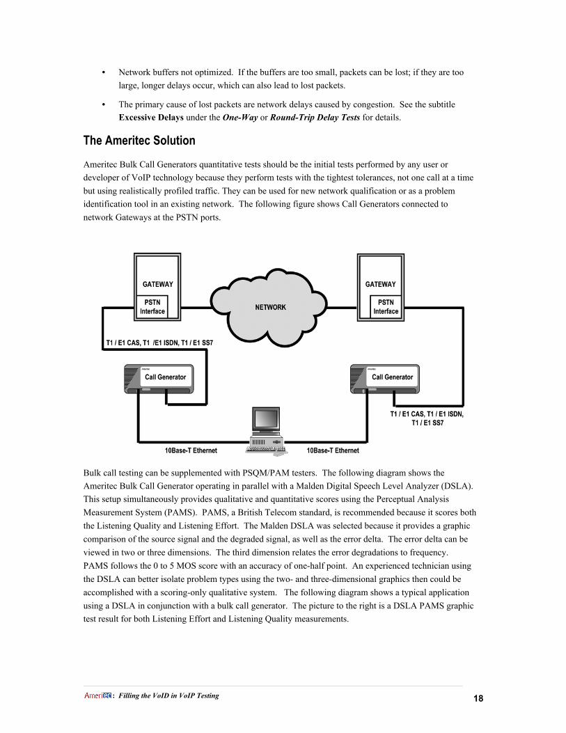
The Ameritec Solution
Ameritec Bulk Call Generators quantitative tests should be the initial tests performed by any user or
developer of VoIP technology because they perform tests with the tightest tolerances, not one call at a time
but using realistically profiled traffic. They can be used for new network qualification or as a problem
identification tool in an existing network. The following figure shows Call Generators connected to
network Gateways at the PSTN ports.
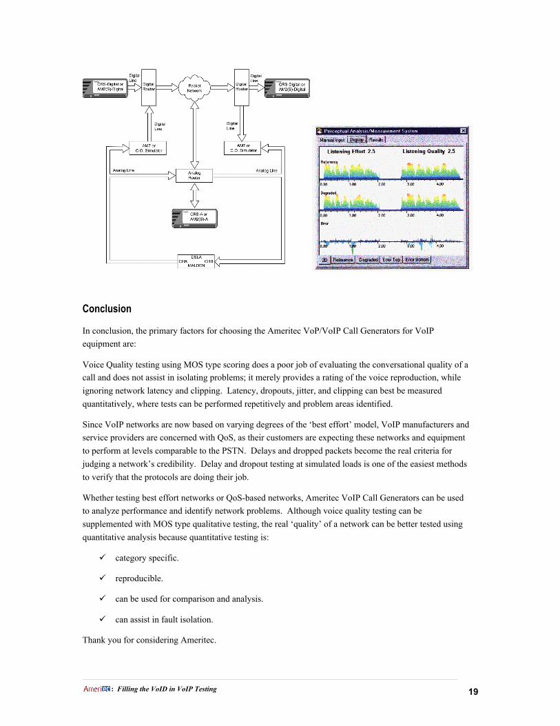
Bulk call testing can be supplemented with PSQM/PAM testers. The following diagram shows the
Ameritec Bulk Call Generator operating in parallel with a Malden Digital Speech Level Analyzer (DSLA).
This setup simultaneously provides qualitative and quantitative scores using the Perceptual Analysis
Measurement System (PAMS). PAMS, a British Telecom standard, is recommended because it scores both
the Listening Quality and Listening Effort. The Malden DSLA was selected because it provides a graphic
comparison of the source signal and the degraded signal, as well as the error delta. The error delta can be
viewed in two or three dimensions. The third dimension relates the error degradations to frequency.
PAMS follows the 0 to 5 MOS score with an accuracy of one-half point. An experienced technician using
the DSLA can better isolate problem types using the two- and three-dimensional graphics then could be
accomplished with a scoring-only qualitative system. The following diagram shows a typical application
using a DSLA in conjunction with a bulk call generator. The picture to the right is a DSLA PAMS graphic
test result for both Listening Effort and Listening Quality measurements.
___________________________________________________________________________________________________________________________________________________________________________________________________________________________________________________________________________________________________________________________________________________________________________________________________________________________________________
: Filling the VoID in VoIP Testing 19
Conclusion
In conclusion, the primary factors for choosing the Ameritec VoP/VoIP Call Generators for VoIP
equipment are:
Voice Quality testing using MOS type scoring does a poor job of evaluating the conversational quality of a
call and does not assist in isolating problems; it merely provides a rating of the voice reproduction, while
ignoring network latency and clipping. Latency, dropouts, jitter, and clipping can best be measured
quantitatively, where tests can be performed repetitively and problem areas identified.
Since VoIP networks are now based on varying degrees of the Ôbest effortÕ model, VoIP manufacturers and
service providers are concerned with QoS, as their customers are expecting these networks and equipment
to perform at levels comparable to the PSTN. Delays and dropped packets become the real criteria for
judging a networkÕs credibility. Delay and dropout testing at simulated loads is one of the easiest methods
to verify that the protocols are doing their job.
Whether testing best effort networks or QoS-based networks, Ameritec VoIP Call Generators can be used
to analyze performance and identify network problems. Although voice quality testing can be
supplemented with MOS type qualitative testing, the real ÔqualityÕ of a network can be better tested using
quantitative analysis because quantitative testing is:
ü category specific.
ü reproducible.
ü can be used for comparison and analysis.
ü can assist in fault isolation.
Thank you for considering Ameritec.

___________________________________________________________________________________________________________________________________________________________________________________________________________________________________________________________________________________________________________________________________________________________________________________________________________________________________________
: Filling the VoID in VoIP Testing 20
Source Material:
Advanced QoS Services for the Intelligent Internet, Cisco Systems White Paper, April 1997
Advances in Speech Enhancements on Voice-over-IP Applications by Jerry Skene, CSD Magazine,March, 2000
An Architecture for Differentiated Services; IETF 2475; Network Working Group: Blake, Black, Carlson, Davies,Wang, Weiss; Internet Society, July 1998
Combining Voice over IP with Policy-Based Quality of Service Introduction, Extreme Network Solutions TechBrief
Designing Global VoIP/ and FoIP Solutions Networks with the Nuvo200Nuvo 200 IP/SSP, MockingbirdNetworks White Paper, 1998
Discussion of Voice over Frame Relay, Frame Relay Forum, 1996
Emerging Technology: Reducing Voice over IP Latency by Gilbert Held, Network Magazine
H.323 Tutorial, Trillium, Web ProForums Tutorials, July 1999
IMTC Voice over IP Forum Service Interoperability Implementation Agreement 1.0, Final Version for Ballot,December 1, 1997
Installing VoIP Systems by Chris Bajorek, Computer Telephony Magazine, August 1, 1999
IP QoS Over ATM by Raj Jain, Ohio State University
IP Quality of Service, Agilent Technologies Application Note, March, 2000
ITU-T G.107: The E-model, a computational model for use in transmission planning (PrepublishedRecommendation)
ITU-T G.108: Application of the E-model: A planning guide
ITU-T G.114: Mean One-Way Propagation Time
ITU-T P.861: Objective quality measurement of telephone-band (300-3400 Hz) speech codecs
Measuring Voice Quality, Listening by the Numbers by David Willis, Network Computing, May 31, 1999
Minimizing VoIP Transmission Delays To Optimize Performance by Jeff Hill, CTI, January 1998
Per Hop Behavior Identification Codes, RFC 2836, IETF, S. Brim, B. Carpenter, F. Le Faucheur, May 2000
Policy Framework QoS Information Model; Policy DiffServ over MPLS Info Model; IETF; Internet Draft, Isoyama& Brunner, NEC Corporation, NEC Europe, Ltd., July 2000
Primer on H.323 Series Standard, DataBeam Corporation White Paper, May 15, 1998
QoS Protocols & Architectures, Stardust.com White Paper, July 8, 1999
Realtime Speech and Voice Transmission on the Internet by Jarkko Ahonen & Arttu Laine, Helsinki Universityof Technology, April 1997
___________________________________________________________________________________________________________________________________________________________________________________________________________________________________________________________________________________________________________________________________________________________________________________________________________________________________________
: Filling the VoID in VoIP Testing P/N183003 21
Role of Voice-Data Integration in Transforming your Business to e-business, IBM White Paper, Sept 1998
Short Overview of QoS Mechanisms and Their Interoperation, Microsoft TechNet White Paper, November 1999
Understanding Latency in IP Telephony by Percy Allan, Brooktrout Technology
Voice/Fax Over IP: Internet, Intranet, and Extranet, Micom White Paper
Voice over Frame Relay White Paper, ACT Networks, 1999
Virtual Private Networks May Push IP Voice Out Of Its Tunnel by Howard Meyers, Internet Telephony, May 1999
Voice Quality in Converging Telephony and IP Networks, Agilent Technologies, Web ProForums Tutorials
Voice Technologies for IP and Frame Relay Networks by Eric Larson and Steve Nikola, Motorola White Paper,1998


