

Fire safety in timber buildings
Technical guideline for Europe
SP Report 2010:19
Excerpt of chapters 5-7 on Structural fire design
for information to JRC - Joint Research Centre and CEN TC 250/SC5 available at the website www.jrc.ec.europa.eu

Excerpt for JRC and CEN TC250/SC5
2
Technical guideline for Europe This guideline has been developed within the European research project FireInTimber (Fire Resistance of Innovative Timber structures). Research partners are
Sweden SP Trätek Birgit Östman, Project coordinator Jürgen König, Joachim Schmid
Finland VTT Esko Mikkola, Tuula Hakkarainen Germany TUM Technische Universität München René Stein, Norman Werther, Stefan Winter
DGfH Matthias Krolak France BPU Blaise Pascal University Abdelhamid Bouchair
CSTB Dhionis Dhima Norway TreSenteret, Wood Centre Harald Landrø UK BRE Building Research Establishment Julie Bregulla Austria HFA Holzforschung Austria Martin Teibinger
UIBK Innsbruck University Hans Hartl TUW Technische Universität Wien Karin Hofstetter
Switzerland ETH Zurich Andrea Frangi Estonia Resand Alar Just Supporting funding organisations are WoodWisdom-Net Research Programme jointly funded by national funding organizations in Sweden, Finland, Germany, France, Norway, UK, Austria, Switzerland and Estonia. European wood industry through BWW Building With Wood under the umbrella of the European Wood Industries CEI Bois. The guideline has been written by the FireInTimber research partners. The following persons are responsible of the chapters: Birgit Östman (Chapters 1, 3, 4 and 12) Esko Mikkola (Chapters 2 and 11) René Stein (Chapters 4.4 and 8) Andrea Frangi (Chapter 5) Jürgen König (Chapter 6) Dhionis Dhima (Chapter 7) Tuula Hakkarainen (Chapter 9) Julie Bregulla (Chapter 10)
Editor: Birgit Östman, SP Trätek, Stockholm
SP Technical Research Institute of Sweden SP Trätek Box 5609 SE-114 86 Stockholm, Sweden Web: www.sp.se; Phone: +46 10 516 50 00 SP Report 2010:19 ISBN 978-91-86319-60-1
Price 50 euro
The full guideline may be ordered at http://www.sp.se/en/publications/Sidor/Publikationer.aspx?RapportId=11001 Translations of this guideline or parts of it need permission from SP Trätek. This English version must be referred to as the original source.
Excerpt for JRC and CEN TC250/SC5
3
Content Guideline Summary 4 5. Separating timber structures 57 5.1 General 57 5.2 Basic requirements on fire compartmentation 57 5.3 Calculations methods 58 5.4 The EN 1995-1-2 design method 58 5.5 Improved design method for separationg function of timber constructions 60 5.5.1 Introduction 5.5.2 Basic values 5.5.3 Position coefiicients 5.5.4 Joint coefficient 5.5.5 Void cavities 5.5.6 Detailing 5.5.7 Other materials 5.6 Examples 71 5.6.1 Worked example 1 5.6.2 Worked example 2 5.6.3 Worked example 3 5.7 References 76
6. Load bearing timber structures 79 6.1 General 79 6.2 Structural stability 79 6.3 Materials 6.3.1 Timber and wood-based materials 6.3.2 Gypsum plasterboard 6.3.3 Insulation materials 6.3.4 Adhesives 6.4 Charring of timber and wood-based panels 81 6.4.1 General 6.4.2 One-dimensional charring 6.4.3 Two-dimensional charring 6.4.4 Effect of protection 6.4.5 Effect of bonded joints 6.5 Mechanical resistance 92 6.5.1 Simplified methods for strength and stiffness parameters 6.5.2 Advanced calculation methods 6.6 Structural elements 97 6.6.1 Beams and columns exposed on three or four sides 6.6.2 Solid timber decks and walls 6.6.3 Timber frame floor and wall assemblies 6.6.4 Light weight timber frame floors with I-joists 6.6.5 Other structural elements 6.7 Calculation vs full-scale testing 125 6.8 References 126
7. Timber connections 129 7.1 General 129 7.2 Design method according to EN 1995-1-2 130 7.3 Other methods proposed for the design of timer connections 131 7.3.1 Timber-to-timber connections 7.3.2 Steel-to-timber connections 7.4 References 139
Excerpt for JRC and CEN TC250/SC5
4
Guideline Summary
Fire Safety in Timber Buildings is the very first Europe-wide technical guideline on the fire safe use of wood products and timber structures in buildings. It is one of the main outcomes of the collaborative European WoodWisdom-Net FireInTimber research project with partners from Austria, Estonia, Finland, Germany, France, Norway, Sweden, Switzerland and UK.
The guideline has been developed with the needs of architects, engineers, appropriate university departments, authorities and building industries in mind, providing information on and showcasing the fire-safe use of timber and wood products in buildings. It aims to provide the latest scientific knowledge on the fire safety of timber structures at European level. The guideline covers the use of design codes (such as the fire part of Eurocode 5), European fire standards and classifications and principles of performance-based design, as well as practical case studies and worked examples.
The guideline focus on structural fire protection in timber structures by providing detailed guidance on load-bearing and separating functions of timber structures under standard fire exposure. New design methods are presented: they have been developed recently, and will be potential input to the next revision of Eurocode 5. Representing state-of-the art knowledge, they have been included here for designers to trial and benefit from. The guideline also includes information on reaction to fire performance of wood products according to the latest European standards. The importance of proper detailing in building design and of quality of workmanship and inspection at building sites is stressed, and practical solutions offered. Means of active fire protection are introduced, and their contribution to meeting fire safety objectives explained.
Exciting new possibilities have recently been noted in timber buildings, with multi-storey applications and large-scale timber façade solutions being increasingly used throughout Europe. Whilst these applications are founded on a long history and tradition, only increased new knowledge of fire safety design has made these advances possible.
Chapter 1, Timber buildings, provides a short introduction to the long-term use of timber buildings and their renaissance in recent years as a sustainable solution to achieving environmental goals. It also describes the legacy of history and traditions and new opportunities to build multi-storey timber buildings based on new knowledge for fire safety design.
Chapter 2, Fire safety in buildings, gives an overview of the basic concepts of fire safety in buildings. It presents information on fire behaviour, fire loads, fire scenarios and fire safety objectives. Means of fulfilling the fire safety objectives are described, for use in all buildings and as a basis for the design solutions in this guideline.
Chapter 3, European system for construction products, presents an overview of the European system for fire safety in buildings, based on the Construction Products Directive (CPD) and its essential requirements. These requirements are mandatory for all European countries. They include the classification systems for reaction to fire of building products, fire resistance of structural elements, external fire performance of roofs, fire protection ability of claddings and structural Eurocodes. Descriptions of how these requirements are applied to wood products and timber structures are given in the following chapters.
Chapter 4, Wood products as linings, floorings, claddings and façades, presents the reaction-to-fire performance of wood products according to the European classification system. A wide range of products is included: wood-based panels, structural timber, glued laminated timber (glulam), solid wood panelling and wood flooring. A new system for the durability of the reaction-to-fire performance of wood products is explained and put into context, and K class performance is presented for wood claddings with fire protection ability. In addition to reaction-to-fire performance, some countries have further requirements for façade claddings, for which at present no European harmonised solution exists. Best practice and state-of the art information on fire scenarios for facades are presented.

Excerpt for JRC and CEN TC250/SC5
5
Chapter 5, Separating timber structures, presents the basic requirements, calculation methods based on component additive design and the Eurocode 5 design method. It also presents an improved design method from recent research as potential input for future revisions of Eurocode 5, and practical examples on how to use the method.
Chapter 6, Load-bearing timber structures, introduces the design methods for verification of the structural stability of timber structures in the event of fire, applying the classification for Criterion R for fire resistance (load-bearing function). Reference is made to Eurocode 5 with respect to charring and strength and stiffness parameters. Alternative design models are presented, as well as design methods for new timber structures, outside the present scope of Eurocode 5.
Chapter 7, Timber connections, overviews the basic requirements for timber connections. The calculation methods in Eurocode 5 are complemented with state-of-the-art design methods, the result of recent research. Both timber-to-timber and steel-to-timber connections are included. The models are described and worked examples presented.
Chapter 8, Fire stops, service installations and detailing in timber structures, deals with the need for adequate detailing in the building structure to prevent fire spread within the building elements to other parts of the building. Special attention is paid to basic principles, fire stops, element joints and building services installations. Several practical examples of detailing in timber structures are included.
Chapter 9, Novel products and their implementation, is aimed primarily at product developers. It describes guidelines for introducing novel structural materials and products. The basic performance requirements and potential solutions for insulating materials, encasing claddings and board materials, thin thermal barriers and fire-retardant wood products are included. The innovation process from idea to approved product ready for the market is outlined.
Chapter 10, Active fire protection, describes how such protection is used to achieve a more flexible fire safety design of buildings and an acceptable level of fire safety in large and/or complex buildings. The chapter introduces common active fire protection systems, including fire detection and alarm systems, fire suppression and smoke control systems. Sprinkler installation provides special benefits for an increased use of wood in buildings especially on visible surfaces, e.g. internal linings and external facade claddings.
Chapter 11, Performance-based design, describes the basic principles of performance-based design, requirements and verification. Fire risk assessment principles are described in terms of objectives, fire safety engineering design, design fires, calculation/simulation methods and statistics. A case study of a probabilistic approach for structural fire safety is also included.
Chapter 12, Quality of construction workmanship and inspection, describes the need for execution and control of workmanship to ensure that the planned fire safety precautions are built in. It also emphasises the need for fire safety at building sites, when all fire safety measures are not yet in place.
The guideline summary is published also as a separate document, SP Info 2010:15, with extended information and illustrations. That summary document is available in several languages: English, Estonian, Finnish, French, German, Italian and Swedish.
Chapter 5 - Separating timber structures – Excerpt for JRC and CEN TC250/SC5
57
5 Separating timber structures
5.1 General
This section gives guidance for the fire design of separating timber structures. Reference is made to
EN 1995-1-2 [5.1], which gives a calculation method for the verification of the separation function of
timber structures (see Annex E of EN 1995-1-2). In addition, it presents a new design method
developed from recent research. The calculation method given in Annex E of EN 1995-1-2 is
informative, and may not be applicable in all European states. Depending on national regulations, the
new design method given in the following may need agreement by national authorities. Hence the
content of this section should be regarded as the state of the art, and the new design method as
potential input for future revisions of EN 1995-1-2 [5.1].
5.2 Basic requirements for fire compartmentation
The main objective of structural fire safety measures is to restrict the spread of fire to the room of
origin by guaranteeing the load-carrying capacity of the structure (Requirement on Mechanical
Resistance R) and the separating function of walls and floors (Requirement on Insulation I and
Integrity E) for the required period of time. The required period of time is normally expressed in terms
of fire resistance, using fire exposure of the standard temperature-time curve, and is specified by the
building regulations. While fire tests are still widely used for the verification of the fire resistance of
timber structures, calculation models are becoming more and more common.
Concerning the basic requirements for fire compartmentation, EN 1995-1-2 [5.1] states:
“Where fire compartmentation is required, the elements forming the boundaries of the fire
compartment shall be designed and constructed in such a way that they maintain their separating
function during the relevant fire exposure. This shall include, when relevant, ensuring that:
– integrity failure does not occur (Criterion E),
– insulation failure does not occur (Criterion I), and
– thermal radiation from the unexposed side is limited.”
Criterion I (insulation) may be assumed to be satisfied where the average temperature rise over the
whole of the non-exposed surface is limited to 140K, and the maximum temperature rise at any point
on that surface does not exceed 180K (for fire exposure of the standard temperature-time curve), thus
preventing ignition of objects in the neighbouring compartment. Criterion E (integrity) may be
assumed to be satisfied when no sustained flaming or hot gases to ignite a cotton pad on the side of the
construction not exposed to fire occur, or no cracks or openings in excess of certain dimensions exist.
There is no risk of fire spread due to thermal radiation when Criterion I (insulation) is satisfied.
Criterion I (insulation) is clearly defined, and could be verified by heat transfer calculations instead of
by testing if thermal material properties could be found as a function of temperature (conductivity and
heat transfer). On the other hand, Criterion E (integrity) is mostly determined by testing, because
calculations are still quite impossible (crack formation, dynamics of hot gases, etc.). For example,
premature integrity failure may occur due to sudden failure of claddings or opening of gaps, which are
often dependent on construction details such as fixings. However, extensive experience of full-scale
testing of wall and floor assemblies made it possible to define some rules about detailing of wall and
Separating structures are used to limit the spread of fire from one fire cell, e g from one
compartment, to another. This chapter presents the basic requirements, calculation methods
based on component additive design and the Eurocode 5 design method. It also presents an
improved design method from recent research as potential input for future revisions of Eurocode
5 and practical examples on how to use the method.
Chapter 5 - Separating timber structures – Excerpt for JRC and CEN TC250/SC5
58
floor assemblies that have been included (for example) in EN 1995-1-2 [5.1]. Thus EN 1995-1-2
assumes that Criterion E (integrity) is satisfied where Criterion I (insulation) has been satisfied and
panels remain fixed to the timber structure on the side not exposed to fire.
5.3 Calculation methods
In timber buildings, walls and floors are mostly built up by adding different layers to form an
assembly. For the calculation of fire resistance with regard to the separation function of timber
assemblies, component additive methods can be used. These methods are thus called component
additive because they determine the fire resistance of a layered construction by adding the contribution
of the different layers to obtain the fire resistance. Reference [5.2] presents and reviews calculation
methods for verification of the separating performance of wall and floor assemblies as used in the
United Kingdom [5.3], Canada [5.4] and Sweden [5.5, 5.6], as well as according to ENV 1995-1-2
[5.7]. The Swedish component additive method builds upon that described in ENV 1995-1-2 and the
Canadian method by taking into account the influence of adjacent materials on the fire performance of
each layer, and therefore describes the real fire performance more accurately.
The EN 1995-1-2 (Annex E) design method is based on modification of the Swedish component
additive method by extending it to floors, including the effect of joints in claddings that are not backed
by members, battens or panels, and applying some of the position coefficients to further test results
that became available during the drafting of EN 1995-1-2. The EN 1995-1-2 design method is capable
of considering claddings made of one or two layers of wood-based panels and gypsum plasterboard,
and also voids or insulation-filled cavities. The insulation may be made of mineral wool.
5.4 The EN 1995-1-2 design method
The analysis method for the separating function of wall and floor assemblies is presented in EN 1995-
1-2 Annex E, which is informative: this means that the method shall be used according to the National
Annex in the country concerned.
EN 1995-1-2 requires verification that the time (tins) that it takes for the temperature to increase
(starting from room temperature) by 140K/180K on the side of the member that is not exposed to fire
is equal to or greater than the required fire resistance period (treq) for the separating function of the
member.
[min]reqins tt (5.1)
The insulation time tins depends on the fire behaviour of the layers used in the assemblies, as well as
the positions and joint configurations of the layers. For simplicity, the time tins can be calculated as the
sum of the contributions of the individual layers to fire resistance, considering different heat transfer
paths (see Figure 5.1).
[min]ttni
1i
i,insins (5.2)
Chapter 5 - Separating timber structures – Excerpt for JRC and CEN TC250/SC5
59
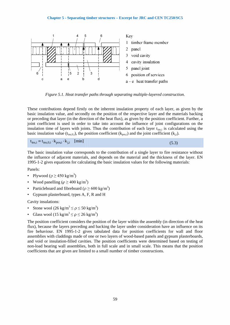
Figure 5.1. Heat transfer paths through separating multiple-layered construction.
These contributions depend firstly on the inherent insulation property of each layer, as given by the
basic insulation value, and secondly on the position of the respective layer and the materials backing
or preceding that layer (in the direction of the heat flux), as given by the position coefficient. Further, a
joint coefficient is used in order to take into account the influence of joint configurations on the
insulation time of layers with joints. Thus the contribution of each layer tins,i is calculated using the
basic insulation value (tins,0,i), the position coefficient (kpos,i) and the joint coefficient (kj,i).
[min]kktt i,ji,posi,0,insi,ins (5.3)
The basic insulation value corresponds to the contribution of a single layer to fire resistance without
the influence of adjacent materials, and depends on the material and the thickness of the layer. EN
1995-1-2 gives equations for calculating the basic insulation values for the following materials:
Panels:
• Plywood ( ≥ 450 kg/m3)
• Wood panelling ( ≥ 400 kg/m3)
• Particleboard and fibreboard ( ≥ 600 kg/m3)
• Gypsum plasterboard, types A, F, R and H
Cavity insulations:
• Stone wool (26 kg/m3 ≤ ≤ 50 kg/m
3)
• Glass wool (15 kg/m3 ≤ ≤ 26 kg/m
3)
The position coefficient considers the position of the layer within the assembly (in direction of the heat
flux), because the layers preceding and backing the layer under consideration have an influence on its
fire behaviour. EN 1995-1-2 gives tabulated data for position coefficients for wall and floor
assemblies with claddings made of one or two layers of wood-based panels and gypsum plasterboards,
and void or insulation-filled cavities. The position coefficients were determined based on testing of
non-load bearing wall assemblies, both in full scale and in small scale. This means that the position
coefficients that are given are limited to a small number of timber constructions.
Chapter 5 - Separating timber structures – Excerpt for JRC and CEN TC250/SC5
60
5.5 Improved design method for separating function of timber
constructions
5.5.1 Introduction
The design method for the verification of the separating function of wall and floor assemblies that is
given in EN 1995-1-2 is based on input data that were deduced from a limited number of fire tests of
wall assemblies, and covers therefore only a limited area of timber structures. For this reason, a
research project on the separating function of timber assemblies was recently completed in
Switzerland. As a final result, an improved design method for determining the separating function of
timber structures has been developed, based on extensive experimental results and finite-element
thermal analysis [5.8, 5.9]. The design method is capable of considering timber assemblies with an
unlimited number of layers made of gypsum plasterboards, wood panels or combinations thereof. The
cavity may be void or filled with mineral wool insulation. The design method considers the following
materials:
• Solid timber with characteristic density ≥ 290 kg/m3
• Cross-laminated timber with characteristic density ≥ 290 kg/m3
• Laminated Veneer Lumber (LVL) with characteristic density ≥ 480 kg/m3
• Oriented Strand Board (OSB) according to EN 300 [5.10] with characteristic density ≥ 550 kg/m
3
• Particleboards according to EN 312 [5.11] with characteristic density ≥ 500 kg/m3
• Fibreboards according to EN 622-2 [5.12], EN 622-3 [5.13] or EN 622-5 [5.14] with characteristic density ≥ 500 kg/m
3
• Plywood according to EN 636 [5.15] with characteristic density ≥ 400 kg/m3
• Gypsum plasterboards Type A, H and F according to EN 520 [5.16]
• Gypsum fibre boards according to EN 15283-2 [5.17]
• Mineral wool insulation according to EN 13162 [5.18].
The developed design method is based on the additive component method given in EN 1995-1-2. The
total fire resistance is therefore taken as the sum of the contributions from the different layers
(claddings, void or insulated cavities), considering different heat transfer paths (see Figure 5.1) and
according to their function and interaction (see Figure 5.2):
n,ins
1ni
1i
i,protins ttt (5.4)
with 1ni
1i
i,prott Sum of the protection times tprot,i of the layers (in the direction of the heat flux)
preceding the last layer of the assembly on the side not exposed to fire [min]
tins,n Insulation time tins,n of the last layer of the assembly on the side not exposed
to fire [min]
Chapter 5 - Separating timber structures – Excerpt for JRC and CEN TC250/SC5
61
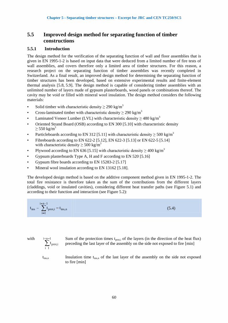
Figure 5.2. Timber frame wall and floor assemblies: numbering and function of the different layers.
Protection and insulation times of the layers can be calculated according to the following general
equations, taking into account the basic values of the layers, the coefficients for the position of the
layers in the assembly and the coefficients for the joint configurations:
i,jiiexp,un,posiexp,,posi,0,proti,prot k)tkkt(t (5.5)
n,jnnexp,,posn,0,insn,ins k)tkt(t (5.6)
with tprot,0,i Basic protection value [min] of layer i (see Figure 5.2 and Table 5.1)
tins,0,n Basic insulation value [min] of the last layer n of the assembly on the
side not exposed to fire (see Figure 5.2 and Table 5.1)
kpos,exp,i, kpos,exp,n Position coefficient that takes into account the influence of layers
preceding the layer considered (see Table 5.2)
kpos,unexp,i Position coefficient that takes into account the influence of layers
backing the layer considered (see Table 5.3)
ti, tn Correction time [min] for layers protected by Type F gypsum
plasterboards as well as gypsum fibreboards (see Table 5.4)
kj,i, kj,n Joint coefficient (see Table 5.5)
The coefficients of the design method (basic values, correction time and position coefficients) were
calculated by extensive finite-element thermal simulations based on physical models for heat transfer
through separating multi-layered construction [5.9, 5.19]. The coefficients given by general equations
permit replacement of the tabulated data given in EN 1995-1-2. The material properties used for the
finite element thermal simulations were calibrated and validated by fire tests performed on unloaded
specimens at Empa (Swiss Laboratories for Materials Testing and Research) in Duebendorf, using fire
exposure of the standard temperature-time curve. The design method was verified with full-scale fire
tests [5.20-5.24], in addition to 27 full-scale fire tests recently performed in Austria [5.25] on slabs and
walls using current EN testing standards. The comparison between test results and the design method
shows that the improved model is able to predict the fire resistance of timber assembly safely. All
details with regard to the development and validation of the design method can be found in [5.9]. The
developed design method significantly improves the EN 1995-1-2 design method, and permits
verification of the separating function of a large number of common timber assemblies. The
coefficients of the design method are explained below.
Chapter 5 - Separating timber structures – Excerpt for JRC and CEN TC250/SC5
62
5.5.2 Basic values
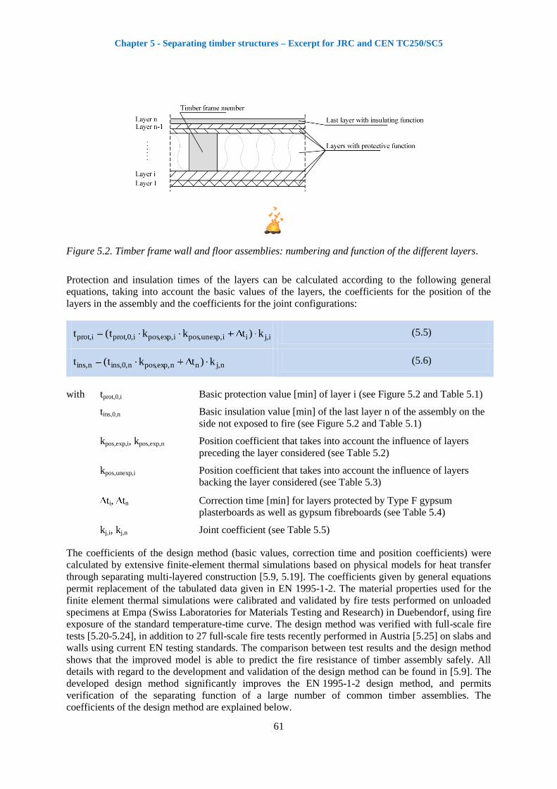
The basic insulation value tins,0 corresponds to the fire resistance of a single layer without the
influence of adjacent materials, i.e. the average temperature rise over the whole of the non-exposed
surface is limited to 140K, and the maximum temperature rise at any point of that surface does not
exceed 180K (for fire exposure of the standard temperature-time curve). These temperature criteria
safely prevent ignition of objects in the neighbouring compartment. The temperature of the layer at the
beginning of the fire on the side exposed to fire, as well as on the non-exposed side, is assumed to be
20 °C. The basic insulation value can be assessed by tests in accordance with (for example) EN 1364-1
[5.26] or FE (finite element) thermal analysis. It should be noted that, for FE thermal analysis, only the
160 °C average temperature criterion is used (see Figure 5.3).
Figure 5.3. Definition of the basic insulation value tins,0 according to EN 1995-1-2.
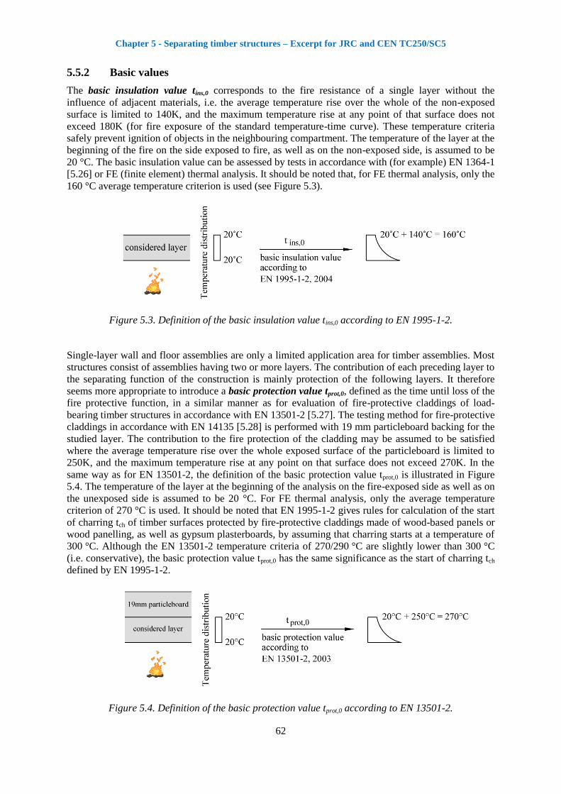
Single-layer wall and floor assemblies are only a limited application area for timber assemblies. Most
structures consist of assemblies having two or more layers. The contribution of each preceding layer to
the separating function of the construction is mainly protection of the following layers. It therefore
seems more appropriate to introduce a basic protection value tprot,0, defined as the time until loss of the
fire protective function, in a similar manner as for evaluation of fire-protective claddings of load-
bearing timber structures in accordance with EN 13501-2 [5.27]. The testing method for fire-protective
claddings in accordance with EN 14135 [5.28] is performed with 19 mm particleboard backing for the
studied layer. The contribution to the fire protection of the cladding may be assumed to be satisfied
where the average temperature rise over the whole exposed surface of the particleboard is limited to
250K, and the maximum temperature rise at any point on that surface does not exceed 270K. In the
same way as for EN 13501-2, the definition of the basic protection value tprot,0 is illustrated in Figure
5.4. The temperature of the layer at the beginning of the analysis on the fire-exposed side as well as on
the unexposed side is assumed to be 20 °C. For FE thermal analysis, only the average temperature
criterion of 270 °C is used. It should be noted that EN 1995-1-2 gives rules for calculation of the start
of charring tch of timber surfaces protected by fire-protective claddings made of wood-based panels or
wood panelling, as well as gypsum plasterboards, by assuming that charring starts at a temperature of
300 °C. Although the EN 13501-2 temperature criteria of 270/290 °C are slightly lower than 300 °C
(i.e. conservative), the basic protection value tprot,0 has the same significance as the start of charring tch
defined by EN 1995-1-2.
Figure 5.4. Definition of the basic protection value tprot,0 according to EN 13501-2.

Chapter 5 - Separating timber structures – Excerpt for JRC and CEN TC250/SC5
63
Table 5.1 gives the equations for calculation of the basic insulation value tins,0 as well as the basic
protection value tprot,0 for different materials that were systematically calculated using finite-element
numerical simulations and verified with fire tests [5.8, 5.9]. Only the basic protection value tprot,0,i is
given for mineral wool insulation, as wall and floor assemblies with the insulation as the last layer of
the assembly are rarely used in buildings.
Table 5.1. Basic insulation value tins,0 and basic protection value tprot,0 for different materials. For mineral wool insulation, only the basic insulation value tins,0 and basic protection value tprot,0 is given, as wall and floor assemblies with the insulation as last layer of the assembly are rarely used in buildings.
Material Basic insulation value tins,0,n [min]
Basic protection value tprot,0,i [min]
Gypsum plasterboard, gypsum fibre board
4,1
i
15
h24
2,1
i
15
h30
Solid timber, cross-laminated timber, LVL
4,1
i
20
h19
0
i
1,1
i h
20
h30
Particleboard, fibreboard
4,1
i
20
h22
0
i
1,1
i h
20
h33
OSB, plywood
4,1
i
20
h16
0
i
1,1
i h
20
h23
Stone wool insulation with ρ ≥ 26 kg/m
3
0 )400)log(75,0(
iiih3,0
Glass wool insulation with ρ ≥ 15 kg/m
3
0
for hi < 40 mm: 0
for hi 40 mm:
3013)046,00007,0( ii h
Where hi: Thickness of the layer considered [mm]
i: Density of the layer considered [kg/m3]
0: One-dimensional charring rate ( 0 = 0,65 mm/min)
The fire behaviour of cross-laminated timber panels is influenced by the behaviour of the adhesive
used for bonding the panels [5.29]. For cross-laminated timber panels with gaps less than 2 mm, where
the char layer does not fall off when the char front has reached a bonded connection, the fire resistance
with regard to the separation function can be calculated in the same way as for solid timber panels,
considering only the total thickness of the cross-laminated timber panels. If the char layer falls off
when the char front has reached a bonded connection, then an increased charring rate must be
considered (see Chapter 6.4.5). In this case, for simplicity, the fire resistance with regard to the
separation function can be calculated considering the single layers of the cross-laminated timber
panels.
Chapter 5 - Separating timber structures – Excerpt for JRC and CEN TC250/SC5
64
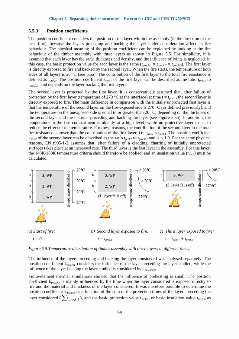
5.5.3 Position coefficients
The position coefficient considers the position of the layer within the assembly (in the direction of the
heat flux), because the layers preceding and backing the layer under consideration affect its fire
behaviour. The physical meaning of the position coefficient can be explained by looking at the fire
behaviour of the timber assembly with three layers as shown in Figure 5.5. For simplicity, it is
assumed that each layer has the same thickness and density, and the influence of joints is neglected. In
this case, the basic protection value for each layer is the same (tprot,0,1 = tprot,0,2 = tprot,0,3). The first layer
is directly exposed to fire and backed by the second layer. When the fire starts, the temperature of both
sides of all layers is 20 °C (see 5.5a). The contribution of the first layer to the total fire resistance is
defined as tprot,1. The position coefficient kpos,1 of the first layer can be described as the ratio tprot,1 to
tprot,0,1, and depends on the layer backing the first layer.
The second layer is protected by the first layer. It is conservatively assumed that, after failure of
protection by the first layer (temperature of 270 °C at the interface) at time t = tprot,1, the second layer is
directly exposed to fire. The main difference in comparison with the initially unprotected first layer is
that the temperature of the second layer on the fire-exposed side is 270 °C (as defined previously), and
the temperature on the unexposed side is equal to or greater than 20 °C, depending on the thickness of
the second layer and the material preceding and backing the layer (see Figure 5.5b). In addition, the
temperature in the fire compartment is already at a high level, while no protective layer exists to
reduce the effect of the temperature. For these reasons, the contribution of the second layer to the total
fire resistance is lower than the contribution of the first layer, i.e. tprot,2 < tprot,1. The position coefficient
kpos,2 of the second layer can be described as the ratio tprot,2 to tprot,0,2 and is < 1.0. For the same physical
reasons, EN 1995-1-2 assumes that, after failure of a cladding, charring of initially unprotected
surfaces takes place at an increased rate. The third layer is the last layer in the assembly. For this layer,
the 140K/180K temperature criteria should therefore be applied, and an insulation value (tins,3) must be
calculated.
a) Start of fire:
t = 0
b) Second layer exposed to fire:
t = tprot,1
c) Third layer exposed to fire:
t = tprot,1 + tprot,2
Figure 5.5.Temperature distribution of timber assembly with three layers at different times.
The influence of the layers preceding and backing the layer considered was analysed separately. The
position coefficient kpos,exp considers the influence of the layer preceding the layer studied, while the
influence of the layer backing the layer studied is considered by kpos,unexp.
Finite-element thermal simulations showed that the influence of preheating is small. The position
coefficient kpos,exp is mainly influenced by the time when the layer considered is exposed directly to
fire and the material and thickness of the layer considered. It was therefore possible to determine the
position coefficient kpos,exp as a function of the sum of the protection times of the layers preceding the
layer considered ( 1i,prott ), and the basic protection value tprot,0,i or basic insulation value tins,0,n as
Chapter 5 - Separating timber structures – Excerpt for JRC and CEN TC250/SC5
65
relevant for the layer considered, making calculation of the position coefficient kpos,exp easier for the
designer (see Table 5.2).
Results of fire tests supported by finite-element thermal simulations showed that the influence of the
layer backing the layer under consideration is small if the backing layer is made of gypsum or wood.
Thus, for simplicity, it is assumed that kpos,unexp = 1.0 for these cases (see Table 5.3). On the other hand,
insulating batts backing the layer caused the layer to heat up more rapidly, reducing the protection
time of the layer. For the different materials, this effect is allowed for by introducing the position
coefficient kpos,unexp (see Table 5.3).
Table 5.2 and 5.3 give the position coefficient kpos,exp and kpos,unexp, that were systemically calculated
using finite-element numerical simulations and verified with fire tests [5.8, 5.9]. For the finite-element
numerical simulations, it was assumed that a layer fails (i.e. falls off) when the temperature on the
unexposed side of the layer reaches 270 °C.
Chapter 5 - Separating timber structures – Excerpt for JRC and CEN TC250/SC5
66
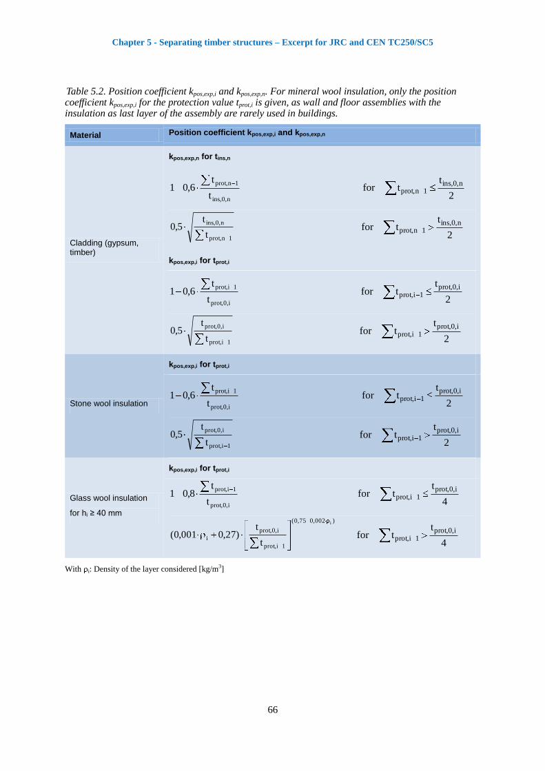
Table 5.2. Position coefficient kpos,exp,i and kpos,exp,n. For mineral wool insulation, only the position coefficient kpos,exp,i for the protection value tprot,i is given, as wall and floor assemblies with the insulation as last layer of the assembly are rarely used in buildings.
Material Position coefficient kpos,exp,i and kpos,exp,n
Cladding (gypsum, timber)
kpos,exp,n for tins,n
n,0,ins
1n,prot
t
t6,01
2
ttfor
n,0,ins1n,prot
1n,prot
n,0,ins
t
t5,0
2
ttfor
n,0,ins1n,prot
kpos,exp,i for tprot,i
i,0,prot
1i,prot
t
t6,01
2
ttfor
i,0,prot1i,prot
1i,prot
i,0,prot
t
t5,0
2
ttfor
i,0,prot1i,prot
Stone wool insulation
kpos,exp,i for tprot,i
i,0,prot
1i,prot
t
t6,01
2
ttfor
i,0,prot1i,prot
1i,prot
i,0,prot
t
t5,0
2
ttfor
i,0,prot1i,prot
Glass wool insulation
for hi ≥ 40 mm
kpos,exp,i for tprot,i
i,0,prot
1i,prot
t
t8,01
4
ttfor
i,0,prot1i,prot
)002,075,0(
1i,prot
i,0,prot
i
i
t
t)27,0001,0(
4
ttfor
i,0,prot1i,prot
With i: Density of the layer considered [kg/m3]
Chapter 5 - Separating timber structures – Excerpt for JRC and CEN TC250/SC5
67
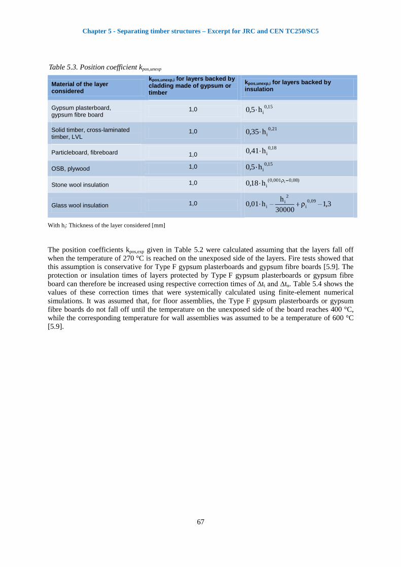
Table 5.3. Position coefficient kpos,unexp
Material of the layer considered
kpos,unexp,i for layers backed by cladding made of gypsum or timber
kpos,unexp,i for layers backed by insulation
Gypsum plasterboard, gypsum fibre board
1,0 15,0
ih5,0
Solid timber, cross-laminated timber, LVL
1,0 21,0
ih35,0
Particleboard, fibreboard 1,0
18,0
ih41,0
OSB, plywood 1,0 15,0
ih5,0
Stone wool insulation 1,0 )08,0001,0(
iih18,0
Glass wool insulation 1,0 3,130000
hh01,0
09,0
i
2
ii
With hi: Thickness of the layer considered [mm]
The position coefficients kpos,exp given in Table 5.2 were calculated assuming that the layers fall off
when the temperature of 270 °C is reached on the unexposed side of the layers. Fire tests showed that
this assumption is conservative for Type F gypsum plasterboards and gypsum fibre boards [5.9]. The
protection or insulation times of layers protected by Type F gypsum plasterboards or gypsum fibre
board can therefore be increased using respective correction times of ∆ti and ∆tn. Table 5.4 shows the
values of these correction times that were systemically calculated using finite-element numerical
simulations. It was assumed that, for floor assemblies, the Type F gypsum plasterboards or gypsum
fibre boards do not fall off until the temperature on the unexposed side of the board reaches 400 °C,
while the corresponding temperature for wall assemblies was assumed to be a temperature of 600 °C
[5.9].
Chapter 5 - Separating timber structures – Excerpt for JRC and CEN TC250/SC5
68
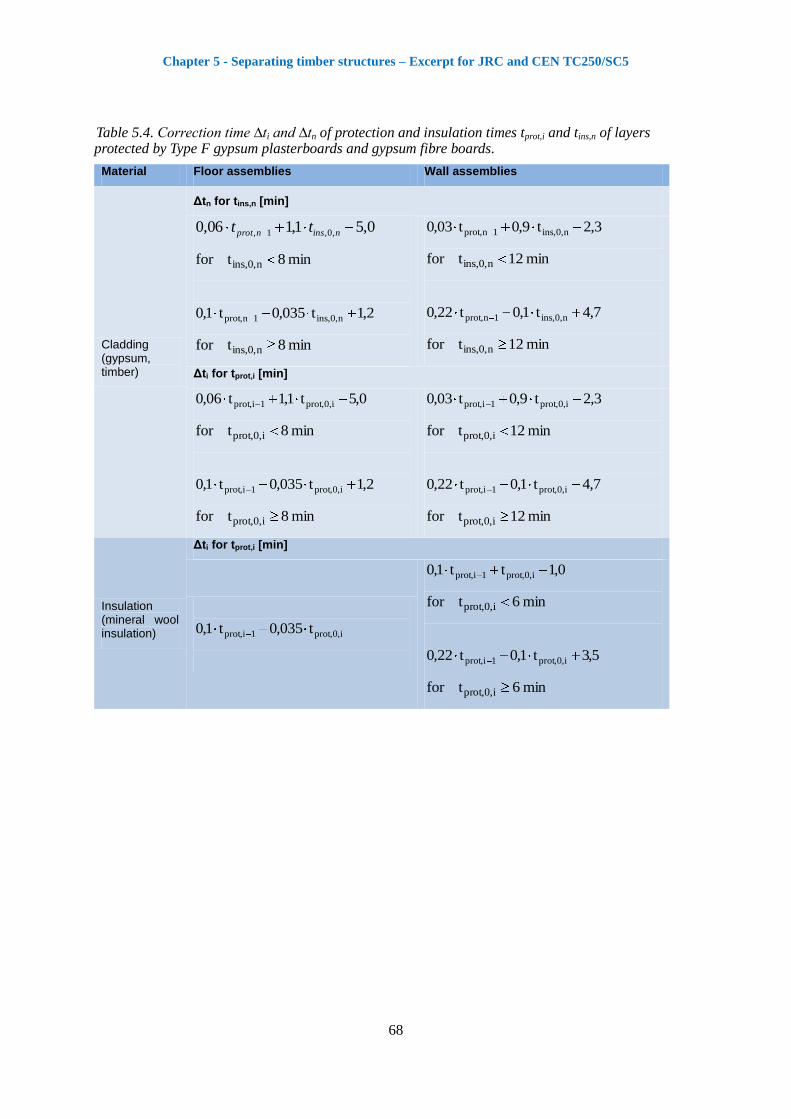
Table 5.4. Correction time ∆ti and ∆tn of protection and insulation times tprot,i and tins,n of layers protected by Type F gypsum plasterboards and gypsum fibre boards.
Material Floor assemblies Wall assemblies
Cladding (gypsum, timber)
Δtn for tins,n [min]
0,51,106,0 ,0,1, ninsnprot tt
min8tfor n,0,ins
2,1t035,0t1,0 n,0,ins1n,prot
min8tfor n,0,ins
3,2t9,0t03,0 n,0,ins1n,prot
min12tfor n,0,ins
7,4t1,0t22,0 n,0,ins1n,prot
min12tfor n,0,ins
Δti for tprot,i [min]
0,5t1,1t06,0 i,0,prot1i,prot
min8tfor i,0,prot
2,1t035,0t1,0 i,0,prot1i,prot
min8tfor i,0,prot
3,2t9,0t03,0 i,0,prot1i,prot
min12tfor i,0,prot
7,4t1,0t22,0 i,0,prot1i,prot
min12tfor i,0,prot
Insulation (mineral wool insulation)
Δti for tprot,i [min]
i,0,prot1i,prot t035,0t1,0
0,1tt1,0 i,0,prot1i,prot
min6tfor i,0,prot
5,3t1,0t22,0 i,0,prot1i,prot
min6tfor i,0,prot

Chapter 5 - Separating timber structures – Excerpt for JRC and CEN TC250/SC5
69
5.5.4 Joint coefficient
The joint coefficient considers the influence of joints in panels (claddings) not backed by battens or
structural members or panels, and their influence on the protection and insulation time of these layers.
EN 1995-1-2 does not permit the use of joints with a width greater than 2 mm. Results of the fire tests
showed that the influence of joints with a width less than 2 mm, and backed by a layer, is small [5.30].
Thus, for simplicity, the design method considers the influence of joints only for the last layer of the
assembly on the unexposed side and for the layer preceding a void cavity (see Table 5.5). For all other
layers, it is assumed that kj,i = 1,0.
Table 5.5. Joint coefficient kj,i
Material Joint type kj,n for tins,n
kj,i for tprot,i
Layer backed by a void cavity
Layer backed by battens or panels or structural members or insulation
Cladding (timber)
0,3 0,3 1,0
0,4 0,4 1,0
0,6 0,6 1,0
no joint 1,0 1,0 1,0
Gypsum plasterboard, gypsum fibre board
0,8 0,8 1,0
no joint 1,0 1,0 1,0
Insulation (mineral wool insulation)
- 0,8 1,0
no joint - 1,0 1,0
Chapter 5 - Separating timber structures – Excerpt for JRC and CEN TC250/SC5
70
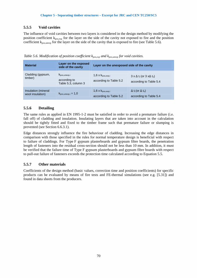
5.5.5 Void cavities
The influence of void cavities between two layers is considered in the design method by modifying the
position coefficient kpos,exp for the layer on the side of the cavity not exposed to fire and the position
coefficient kpos,unexp for the layer on the side of the cavity that is exposed to fire (see Table 5.6).
Table 5.6. Modification of position coefficient kpos,exp and kpos,unexp for void cavities.
Material Layer on the exposed side of the cavity
Layer on the unexposed side of the cavity
Cladding (gypsum, timber)
kpos,unexp,i
according to Table 5.3, column 3
1,6 x kpos,exp,i
according to Table 5.2
3 x Δ ti (or 3 xΔ tn)
according to Table 5.4
Insulation (mineral wool insulation) kpos,unexp,i = 1,0
1,6 x kpos,exp,i
according to Table 5.2
Δ ti (or Δ tn)
according to Table 5.4
5.5.6 Detailing
The same rules as applied in EN 1995-1-2 must be satisfied in order to avoid a premature failure (i.e.
fall off) of cladding and insulation. Insulating layers that are taken into account in the calculation
should be tightly fitted and fixed to the timber frame such that premature failure or slumping is
prevented (see Section 6.6.3.1).
Edge distances strongly influence the fire behaviour of cladding. Increasing the edge distances in
comparison with those specified in the rules for normal temperature design is beneficial with respect
to failure of claddings. For Type F gypsum plasterboards and gypsum fibre boards, the penetration
length of fasteners into the residual cross-section should not be less than 10 mm. In addition, it must
be verified that the failure time of Type F gypsum plasterboards and gypsum fibre boards with respect
to pull-out failure of fasteners exceeds the protection time calculated according to Equation 5.5.
5.5.7 Other materials
Coefficients of the design method (basic values, correction time and position coefficients) for specific
products can be evaluated by means of fire tests and FE-thermal simulations (see e.g. [5.31]) and
found in data sheets from the producers.

Chapter 5 - Separating timber structures – Excerpt for JRC and CEN TC250/SC5
71
5.6 Examples
The following (Sections 5.6.1 - 5.6.3) present three examples of verification of the separation function
of timber structures using the improved design method.
5.6.1 Worked example 1
A timber floor structure consists of joists and claddings made of timber boards and gypsum
plasterboards (see Figure 5.6). The cavities of the timber floor are completely filled with stone wool
insulation, with a density of 30 kg/m3. The joints of the decking (20 mm thick solid timber panels) are
single tongued and grooved with a maximum gap width of 2 mm. The required fire resistance is EI 30.
Figure 5.6. Cross-section of the timber frame floor assembly.
The insulation time tins of the timber floor should be calculated considering different heat transfer
paths. However, for this example, only Heat Transfer Path 3 will be analysed (see Figure 5.6).
An insulation time must be calculated for the last layer of the floor assembly on the unexposed side
(solid timber panel), while for the other layers with protective function a protection time must be
calculated.
Protection time of gypsum plasterboard Type A (Layer 1)
min1,2415
5,1230
15
h30t
2,12,1
11,0,prot
0,1k 1exp,,pos (no layer preceding the gypsum plasterboard)
0,1k 1exp,un,pos (OSB backing the gypsum plasterboard)
0,1k 1,j (OSB backing the gypsum plasterboard)
min1,240,100,10,11,24k)tkkt(t 1,j11exp,un,pos1exp,,pos1,0,prot1,prot
Protection time of OSB (Layer 2)
min1,1320
1223
20
h23t
1,11,1
22,0,prot
Chapter 5 - Separating timber structures – Excerpt for JRC and CEN TC250/SC5
72
37,01,24
1,135,0k
2
1,131,24
t
t5,0k
2
tt 2exp,,pos1i
1ii,prot
2,0,prot
2exp,,pos
2,0,prot1i
1ii,prot
73,0125,0h5,0k 15,015,022exp,un,pos
(insulation backing the OSB)
0,1k 2,j (insulation backing the OSB)
3,5min0,1073,037,01,13k)tkkt(t 2,j22exp,un,pos2exp,,pos2,0,prot2,prot
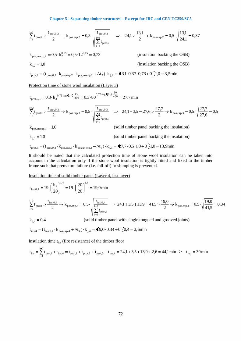
Protection time of stone wool insulation (Layer 3)
min7,27803,0h3,0t 400
30 30log75,0
400 log75,0
33,0,prot
33
5,06,27
7,275,0k
2
7,276,275,31,24
t
t5,0k
2
tt 3exp,,pos2i
1ii,prot
3,0,prot
3exp,,pos
3,0,prot2i
1ii,prot
0,1k 3exp,un,pos (solid timber panel backing the insulation)
0,1k 3,j (solid timber panel backing the insulation)
13,9min0,100,15,07,27k)tkkt(t 3,j33exp,un,pos3exp,,pos3,0,prot3,prot
It should be noted that the calculated protection time of stone wool insulation can be taken into
account in the calculation only if the stone wool insulation is tightly fitted and fixed to the timber
frame such that premature failure (i.e. fall-off) or slumping is prevented.
Insulation time of solid timber panel (Layer 4, last layer)
min0,1920
2019
20
h19t
4,14,1
44,0,ins
34,05,41
0,195,0k
2
0,195,419,135,31,24
t
t5,0k
2
tt 4,exp,pos3i
1ii,prot
4,0,ins
4,exp,pos
4,0,ins3i
1ii,prot
4,0k 4,j (solid timber panel with single tongued and grooved joints)
2,6min4,0034,00,19k)tkt(t 4,j44exp,,pos4,0,ins4,ins
Insulation time tins (fire resistance) of the timber floor
min30tmin1,446,29,135,31,24ttttttt req4,ins3,prot2,prot1,prot4,ins
3i
1ii,protins
Chapter 5 - Separating timber structures – Excerpt for JRC and CEN TC250/SC5
73
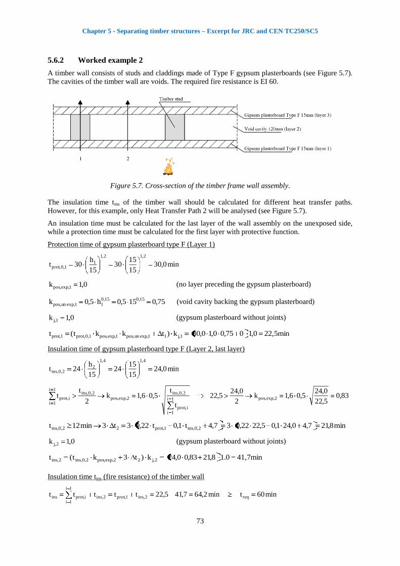
5.6.2 Worked example 2
A timber wall consists of studs and claddings made of Type F gypsum plasterboards (see Figure 5.7).
The cavities of the timber wall are voids. The required fire resistance is EI 60.
Figure 5.7. Cross-section of the timber frame wall assembly.
The insulation time tins of the timber wall should be calculated for different heat transfer paths.
However, for this example, only Heat Transfer Path 2 will be analysed (see Figure 5.7).
An insulation time must be calculated for the last layer of the wall assembly on the unexposed side,
while a protection time must be calculated for the first layer with protective function.
Protection time of gypsum plasterboard type F (Layer 1)
min0,3015
1530
15
h30t
2,12,1
11,0,prot
0,1k 1exp,,pos (no layer preceding the gypsum plasterboard)
75,0155,0h5,0k 15,015,011exp,un,pos
(void cavity backing the gypsum plasterboard)
0,1k 1,j (gypsum plasterboard without joints)
22,5min0,1075,00,10,30k)tkkt(t 1,j11exp,un,pos1exp,,pos1,0,prot1,prot
Insulation time of gypsum plasterboard type F (Layer 2, last layer)
min0,2415
1524
15
h24t
4,14,1
22,0,ins
83,05,22
0,245,06,1k
2
0,245,22
t
t5,06,1k
2
tt 2exp,,pos1i
1ii,prot
2,0,ins2exp,,pos
2,0,ins1i
1ii,prot
min8,217,40,241,05,2222,037,4t1,0t22,03t3min12t 2,0,ins1,prot22,0,ins
0,1k 2,j (gypsum plasterboard without joints)
41,7min0.18,2183,00,24k)t3kt(t 2,j22exp,,pos2,0,ins2,ins
Insulation time tins (fire resistance) of the timber wall
min60tmin2,647,415,22ttttt req2,ins1,prot2,ins
1i
1ii,protins

Chapter 5 - Separating timber structures – Excerpt for JRC and CEN TC250/SC5
74
5.6.3 Worked example 3
A timber floor consists of joists and claddings made of timber boards and gypsum plasterboards (see
Figure 5.8). The cavities of the timber floor are completely filled with glass wool insulation with a
density of 20 kg/m3. The joints of the decking (20 mm thick solid timber panels) are single tongued
and grooved with a maximum gap width of 2 mm. The required fire resistance is EI 30.
Figure 5 8. Cross-section of the timber frame floor assembly.
The insulation time tins of the timber floor should be calculated for different heat transfer paths.
However, for this example, only Heat Transfer Path 3 will be analysed (see Figure 5.8).
An insulation time must be calculated for the last layer of the floor assembly on the unexposed side
(solid timber panel), while a protection time must be calculated for the other layers with protective
functions.
Protection time of Type F gypsum plasterboard (Layer 1)
min3015
1530
15
h30t
2,12,1
11,0,prot
0,1k 1exp,,pos (no layer preceding the gypsum plasterboard)
0,1k 1exp,un,pos (Type A gypsum plasterboard backing the Type F gypsum plasterboard)
0,1k 1,j (Type A gypsum plasterboard backing the Type F gypsum plasterboard)
min300,100,10,130k)tkkt(t 1,j11exp,un,pos1exp,,pos1,0,prot1,prot
Protection time of gypsum plasterboard Type A (Layer 2)
min1,2415
5,1230
15
h30t
2,12,1
22,0,prot
45,030
1,245,0k
2
1,2430
t
t5,0k
2
tt 2exp,,pos1i
1ii,prot
2,0,prot
2exp,,pos
2,0,prot1i
1ii,prot
73,05,125,0h5,0k 15,015,022exp,un,pos
(insulation backing the Type A gypsum plasterboard)
min3,32,11,24035,0301,02,1t035,0t1,0tmin8t 2,0,prot1,prot22,0,prot
0,1k 2,j (insulation backing the Type A gypsum plasterboard)
Chapter 5 - Separating timber structures – Excerpt for JRC and CEN TC250/SC5
75
11,2min0,13,373,045,01,24k)tkkt(t 2,j22exp,un,pos2exp,,pos2,0,prot2,prot
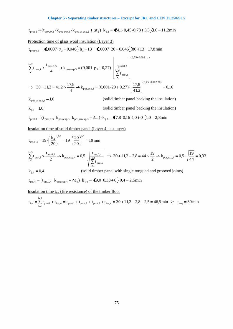
Protection time of glass wool insulation (Layer 3)
min8,171380046,0200007,013h046,00007,0t 333,0,prot
16,02,41
8,17)27,020001,0(k
4
8,172,412,1130
t
t)27,0001,0(k
4
tt
)20002.075,0(
3exp,,pos
)002.075,0(
2i
1ii,prot
3,0,prot
33exp,,pos
3,0,prot2i
1ii,prot
3
0,1k 3exp,un,pos (solid timber panel backing the insulation)
0,1k 3,j (solid timber panel backing the insulation)
2,8min0,100,116,08,17k)tkkt(t 3,j33exp,un,pos3exp,,pos3,0,prot3,prot
Insulation time of solid timber panel (Layer 4, last layer)
min1920
2019
20
h19t
4,14,1
44,0,ins
33,044
195,0k
2
19448,22,1130
t
t5,0k
2
tt 4exp,,pos3i
1ii,prot
4,0,ins4exp,,pos
4,0,ins3i
1ii,prot
4,0k 4,j (solid timber panel with single tongued and grooved joints)
2,5min4,0033,00,19k)tkt(t 4,j44,exp,pos4,0,ins4,ins
Insulation time tins (fire resistance) of the timber floor
min30tmin5,465,28,22,1130ttttttt req4,ins3,prot2,prot1,prot4,ins
3i
1ii,protins
Chapter 5 - Separating timber structures – Excerpt for JRC and CEN TC250/SC5
76
5.7 References
[5.1] EN 1995-1-2, Eurocode 5. Design of timber structures, Part 1-2: General – Structural fire
design, European Standard, CEN, Brussels, 2004.
[5.2] König J, Oksanen T, Towler K. A review of component additive methods used for the
determination of fire resistance of separating light timber frame construction, International
Council for Research and Innovation in Building and Construction, Working Commission
W18 – Timber Structures, Delft, Netherlands, CIB-W18/33-16-3, 2000.
[5.3] British Standard BS 5268-4. Structural use of timber - Section 4.2. Recommendations for
calculating fire resistance of timber stud walls and joisted floor constructions, BSI, 1990.
[5.4] National Building Code of Canada NBCC - Volume 2. Canadian Commission on Building and
Fire Codes, Institute for Research in Construction, National Research Council of Canada,
Ottawa, Canada, 2005.
[5.5] Norén J. Additionsmetoden – Beräkning av brandmotstånd hos avskiljande väggar (Addition
method – Calculation of fire resistance for separating wood frame walls), Trätek – Swedish
Institute for Wood Technology Research, Report I 9312070, 1994.
[5.6] Östman B, König J, Norén J. Contribution to fire resistance of timber frame assemblies by
means of fire protective boards, Proceedings of the 3rd International Fire and Materials
Conference, Washington D.C., 1994.
[5.7] ENV 1995-1-2, Eurocode 5. Design of timber structures, Part 1-2: General rules – Structural
fire design, European Prestandard, CEN, Brussels, 1994.
[5.8] Schleifer V, Frangi A, Fontana M. Experimentelle Untersuchungen zum Brandverhalten von
Plattenelementen, Institute of Structural Engineering IBK, ETH Zurich, IBK-report No. 302,
ISBN 978-3-7281-3149-2, May 2007, vdf Hochschulverlag AG.
[5.9] Schleifer V. Zum Verhalten von raumabschliessenden mehrschichtigen Holzbauteilen im
Brandfall, PhD Thesis ETH No. 18156, ETH Zurich, 2009.
[5.10] EN 300. Oriented Strand Boards (OSB). Definitions, classification and specifications,
European Standard, CEN, Brussels, 2006.
[5.11] EN 312. Particleboards - Specifications, European Standard, CEN, Brussels, 2003.
[5.12] EN 622-2. Fibreboards - Specifications - Part 2: Requirements for hardboards, European
Standard, CEN, Brussels, 2004.
[5.13] EN 622-3. Fibreboards - Specifications - Part 3: Requirements for medium boards, European
Standard, CEN, Brussels, 2004.
[5.14] EN 622-5. Fibreboards - Specifications - Part 5: Requirements for dry process boards (MDF),
European Standard, CEN, Brussels, 2006.
[5.15] EN 636. Plywood - Specifications, European Standard, CEN, Brussels, 2003.
[5.16] EN 520. Gypsum plasterboards - Definitions, requirements and test methods, European
Standard, CEN, Brussels, 2004.
[5.17] EN 15283-2. Gypsum boards with fibrous reinforcement - Definitions, requirements and test
methods - Part 2: Gypsum fibre boards, European Standard, CEN, Brussels, 2008.
[5.18] EN 13162. Thermal insulation products for buildings - Factory made mineral wool (MW)
products – Specification, European Standard, CEN, Brussels, 2001.
[5.19] Frangi A, Schleifer V, Fontana M. Design model for the verification of the separating function
of light timber frame assemblies, Engineering Structures, 32: 1184–1195, 2010.
Chapter 5 - Separating timber structures – Excerpt for JRC and CEN TC250/SC5
77
[5.20] König J. Fire resistance of timber joists and load bearing wall frames, Trätek, Rapport I
99412071, Stockholm, 1995.
[5.21] König J, Norén J. Timber frame assemblies exposed to standard and parametric fires - Part 1:
Fire tests, Trätek, Rapport I 9702015, Stockholm, 1997.
[5.22] Sultan M A, Séguin Y P, Leroux P. Results of fire resistance tests on full-scale floor
assemblies, Internal Report IR-764, Institute for Research in Construction, National Research
Council of Canada, Ottawa, Canada, 1998.
[5.23] Sultan M A, Lougheed G D. Results of fire resistance tests on full scale gypsum board wall
assemblies, IR-833, Institute for Research in Construction, National Research Council of
Canada, 2002.
[5.24] Collier P C R, Buchanan A H. Fire resistance of lightweight timber framed walls, Fire
Technology, 38, 125-145, 2002.
[5.25] Teibinger M, Matzinger I, Charwat-Pessler J. Grundlagen zur Bewertung des
Feuerwiderstandes von Holzrahmenkonstruktionen, Endbericht, Holzforschung Austria, 2010.
[5.26] EN 1364-1. Fire resistance tests for non-loadbearing elements – Part 1: Walls, European
Standard, CEN, Brussels, 1999.
[5.27] EN 13501-2. Fire classification of construction products and building elements – Part 2:
Classification using data from fire resistance tests, excluding ventilation services, European
Standard, CEN, Brussels, 2003.
[5.28] EN 14135. Coverings – Determination of fire protection ability, European Standard, CEN,
Brussels, 2004.
[5.29] Frangi A, Fontana M, Hugi E, Jöbstl R. Experimental analysis of cross-laminated timber
panels in fire, Fire Safety Journal 44, 1078–1087, 2009.
[5.30] Richardson LR, Batista M. Fire resistance of timber decking for heavy timber construction,
Fire and Materials 25, 21–9, 2001.
[5.31] Schleifer V, Frangi A. Untersuchungen zum Raumabschluss von Bauteilen mit Isoresist 1000,
Institute of Structural Engineering IBK, ETH Zurich, Research report, April 2009.

Chapter 6 – Load-bearing structures – Excerpt for JRC and CEN TC250/SC5
79
6 Load-bearing timber structures
This chapter presents design methods for the verification of structural stability of timber structures in
the event of fire, applying the classification for criterion R for fire resistance (load-bearing function).
Reference is made to Eurocode 5, EN 1995-1-2, with respect to charring and strength and stiffness
parameters. Alternative design models are presented, as well as design methods for new timber
structures, outside the present scope of Eurocode 5.
Equation Section 6
6.1 General
This section gives guidance for structural fire design of timber structures. Reference is made to EN
1995-1-2 [6.1], including Corrigenda [6.2][6.3] and other parts of Structural Eurocodes and, where
new knowledge is available, to other references. Some of the design rules given in informative
annexes to Eurocodes may not be applicable in all European States, see National annexes to
Eurocodes. Depending on national regulations, some of the new design methods given in the following
may need agreement by the Competent Authority. Hence the content of this section should be regarded
as the state of the art, and new items as potential input for future revisions of EN 1995-1-2 [6.1]. Fire
scenarios other than standard fire exposure are outside the scope of this chapter.
6.2 Structural stability
The model of the structural system adopted for the design must reflect the performance of the structure
in a fire situation. EN 1995-1-2 [6.1] provides the following alternatives for verification of the
structural performance of the building:
Member analysis
Analysis of parts of the structure
Global structural analysis.
The structural system may be different in a fire situation, e.g. where a structural member is braced at
ambient temperature and the bracing fails in the fire situation, the member must be regarded as
unbraced in the structural fire design, see also 6.6.3.1. Elements that are used for the stabilisation of
the building, e.g. wood-based panels or gypsum plasterboard in wall or floor diaphragms, often lose
their racking resistance in a fire situation unless they are protected from the fire. This effect on the
global structural system must therefore be taken into account. In redundant structural systems it may
be advantageous to allow for premature failure if an alternative load path is possible, e.g. a column in
a fire compartment.
Unlike steel and concrete, thermal expansion of timber need not be taken into account.
6.3 Materials
6.3.1 Timber and wood-based materials
The main properties of timber and wood-based materials relevant in structural fire design are charring
and the reduction of strength and stiffness properties due to elevated temperature. For simplified
design, it is sufficient to consider charring, see 6.4 and simplified model strength verification, see
6.5.1. For advanced calculations (see 6.5.2), thermo-mechanical properties of softwoods (solid timber,
glued-laminated timber and LVL) are given in EN 1995-1-2 Annex B. Thermal properties of OSB,
plywood and wood fibreboard are given in 6.5.2.
Chapter 6 – Load-bearing structures – Excerpt for JRC and CEN TC250/SC5
80
6.3.2 Gypsum plasterboard
Some properties of gypsum plasterboards and gypsum fibreboards are given in EN 520 [6.4] and EN
15283-2 [6.5] respectively. With respect to performance in fire of these boards, these European
standards give insufficient information, such as thermal properties for heat transfer calculations and
mechanical properties in fire. The latter are important with respect to failure of gypsum plasterboard
claddings due to thermal degradation. Failure times (i.e. fall-off times) of gypsum plasterboards are
given in EN 1995-1-2 [6.1] for gypsum plasterboards Type A and H. For Type F, they must be
determined on the basis of tests. Some data on failure times of gypsum plasterboards are given in
[6.6], see 6.4.4.5.
For thermal properties of gypsum plasterboards, see 6.5.2.
6.3.3 Insulation materials
6.3.3.1 Mineral wool
EN 13162 [6.7] gives product characteristics of mineral wool (i.e. stone wool and glass wool) such as
thermal conductivity, density and other. However, this European standard does not classify mineral
wool in terms needed for structural fire design. The designer knows, for example, that stone wool
performs better than glass wool when directly exposed to fire, however no relevant test method exists
to quantify the difference in terms of product properties. It is also known that glass wool and stone
wool perform equally when protected from direct flames, i.e. by gypsum plasterboard.
Both for stone wool and glass wool there is a weak relationship between fire performance and density.
Density is therefore not sufficient to characterise the fire performance of the insulation. This can be
determined by fire testing. The terminology used below is therefore traditional and recognized by the
designer. Where density requirements are given, they refer to the requirements given in EN 1995-1-2
[6.1]. For better specification of mineral wool, a new classification of mineral wool is needed with
respect to its performance in fire. Such classification should permit the inclusion of new types of
mineral wool in accordance with EN 13162, such as one that has recently been developed and
introduced on the marked. See also 9.1.1.
For thermal properties of mineral wool for thermal analyses, see 6.5.2.
6.3.3.2 Cellulose insulation
The fire performance cellulose insulation must be determined by fire testing. For their use in timber
structures, of special interest is the degree of their capability of providing protection of timber
members, to resist smouldering, shrinkage and surface recession. See also 9.1.1.
6.3.3.3 Other insulation materials
For more information, see 9.1.1.
6.3.4 Adhesives
EN 1995-1-2 Clause 5.2 requires that “adhesives for structural purposes shall produce joints of such
strength and durability that the integrity of the bond is maintained in the assigned fire resistance
period. For bonding of wood to wood, wood to wood-based materials or wood-based materials to
wood-based materials, adhesives of phenol-formaldehyde and aminoplastic type 1 adhesive according
to EN 301 [6.8] may be used. For plywood and LVL, adhesives according to EN 314 may be used”.
Furthermore, since 1994 one component polyurethane (PUR) adhesives have been classified as Type 1
adhesive according to EN 301 and additional requirements. In 2008 the adhesive classification
standard for PUR adhesives, EN 15425 [6.9], was published.

Chapter 6 – Load-bearing structures – Excerpt for JRC and CEN TC250/SC5
81
EN 301 [6.8] does not require any testing at elevated temperatures for phenolic and aminoplastic
adhesives. According to EN 15425 [6.9], PUR adhesives are required to be tested at 70°C, being held
over two weeks under constant loading of the specimens. The intention of this scenario is to cover for
elevated temperatures in timber structures e.g. caused by the impact of sustained sunlight. Therefore, it
has been suggested that there is a need to establish a new classification system for all types of
adhesives with respect to their performance in fire [6.10] [6.15] and to develop relevant test methods.
For effect on charring in laminated members, see 6.4.5, for effect on finger joint strength, see 6.6.4.5.
6.4 Charring of timber and wood-based panels
6.4.1 General
Timber members exposed to fire exhibit charring unless they are protected during the relevant time of
fire exposure. For calculation of the resistance of timber members, the original cross-section is
reduced by the charring depth.
In the following, charring of timber members is divided into:
One-dimensional charring as a physical property for a specific species, or timber of specific
density or strength class, see 6.4.2 below.
Two-dimensional charring, including the effects of cross-sectional dimensions and other effects,
see 6.4.3 below.
The charring rates are applicable for any orientation of fire-exposed surfaces and direction of fire
exposure, i.e. there is no distinction between vertical or horizontal surfaces. For example, for surfaces
on floors with fire exposure from above, the same charring rates apply as for surfaces with fire
exposure from below. For fire exposure from above, fall-off of fire protective claddings supported by
a decking are not relevant and need not be considered.
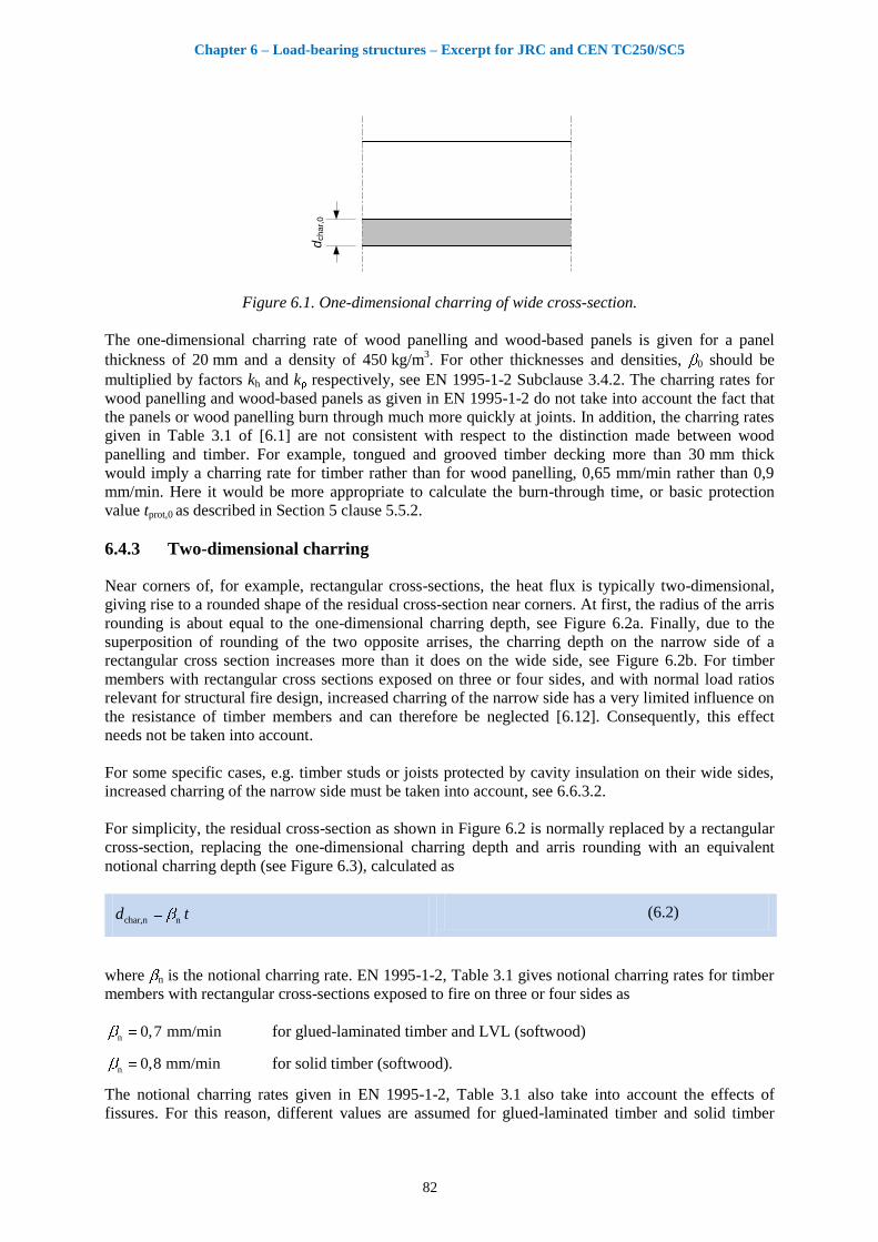
6.4.2 One-dimensional charring
As a basic value, the one-dimensional charring rate 0 is the charring rate observed for one-
dimensional heat transfer under standard fire exposure of an unprotected semi-infinite timber slab
without any fissures or gaps. The conditions are similar in a slab of limited thickness, see Figure 6.1,
or in wide timber cross-sections remote from corners.
The one dimensional charring depth dchar,0 is expressed as
char,0 0d t (6.1)
where t is the time of fire exposure and 0 is the one-dimensional charring rate perpendicular to the
grain, as shown in Table 3.1 of EN 1995-1-2 [6.1]. For charring in the direction of the grain, these
charring rates should be doubled. The one-dimensional charring rate given for softwoods is valid for
European species (0,65 mm/min); it may also be applicable to other species, e.g. radiata pine, while
the charring rates of several North American softwoods may considerably deviate, see Schaffer [6.11].
The influence of density within European strength classes for softwoods (solid timber, glued-
laminated timber and LVL) is small and therefore neglected.
Chapter 6 – Load-bearing structures – Excerpt for JRC and CEN TC250/SC5
82
dch
ar,
0
Figure 6.1. One-dimensional charring of wide cross-section.
The one-dimensional charring rate of wood panelling and wood-based panels is given for a panel
thickness of 20 mm and a density of 450 kg/m3. For other thicknesses and densities, 0 should be
multiplied by factors kh and k respectively, see EN 1995-1-2 Subclause 3.4.2. The charring rates for
wood panelling and wood-based panels as given in EN 1995-1-2 do not take into account the fact that
the panels or wood panelling burn through much more quickly at joints. In addition, the charring rates
given in Table 3.1 of [6.1] are not consistent with respect to the distinction made between wood
panelling and timber. For example, tongued and grooved timber decking more than 30 mm thick
would imply a charring rate for timber rather than for wood panelling, 0,65 mm/min rather than 0,9
mm/min. Here it would be more appropriate to calculate the burn-through time, or basic protection
value tprot,0 as described in Section 5 clause 5.5.2.
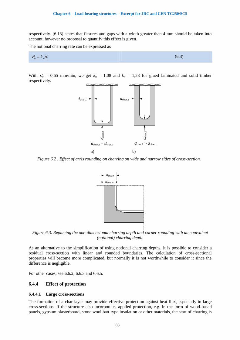
6.4.3 Two-dimensional charring
Near corners of, for example, rectangular cross-sections, the heat flux is typically two-dimensional,
giving rise to a rounded shape of the residual cross-section near corners. At first, the radius of the arris
rounding is about equal to the one-dimensional charring depth, see Figure 6.2a. Finally, due to the
superposition of rounding of the two opposite arrises, the charring depth on the narrow side of a
rectangular cross section increases more than it does on the wide side, see Figure 6.2b. For timber
members with rectangular cross sections exposed on three or four sides, and with normal load ratios
relevant for structural fire design, increased charring of the narrow side has a very limited influence on
the resistance of timber members and can therefore be neglected [6.12]. Consequently, this effect
needs not be taken into account.
For some specific cases, e.g. timber studs or joists protected by cavity insulation on their wide sides,
increased charring of the narrow side must be taken into account, see 6.6.3.2.
For simplicity, the residual cross-section as shown in Figure 6.2 is normally replaced by a rectangular
cross-section, replacing the one-dimensional charring depth and arris rounding with an equivalent
notional charring depth (see Figure 6.3), calculated as
char,n nd t (6.2)
where n is the notional charring rate. EN 1995-1-2, Table 3.1 gives notional charring rates for timber
members with rectangular cross-sections exposed to fire on three or four sides as
n 0,7 mm/min for glued-laminated timber and LVL (softwood)
n 0,8 mm/min for solid timber (softwood).
The notional charring rates given in EN 1995-1-2, Table 3.1 also take into account the effects of
fissures. For this reason, different values are assumed for glued-laminated timber and solid timber
Chapter 6 – Load-bearing structures – Excerpt for JRC and CEN TC250/SC5
83
respectively. [6.13] states that fissures and gaps with a width greater than 4 mm should be taken into
account, however no proposal to quantify this effect is given.
The notional charring rate can be expressed as
n n 0k (6.3)
With 0 = 0,65 mm/min, we get kn = 1,08 and kn = 1,23 for glued laminated and solid timber
respectively.
dchar,1
dchar,
2
dchar,1
dchar,
2dchar,2 = dchar,1 dchar,2 > dchar,1
a) b)
Figure 6.2 . Effect of arris rounding on charring on wide and narrow sides of cross-section.
dchar,0
dchar,n
Figure 6.3. Replacing the one-dimensional charring depth and corner rounding with an equivalent
(notional) charring depth.
As an alternative to the simplification of using notional charring depths, it is possible to consider a
residual cross-section with linear and rounded boundaries. The calculation of cross-sectional
properties will become more complicated, but normally it is not worthwhile to consider it since the
difference is negligible.
For other cases, see 6.6.2, 6.6.3 and 6.6.5.
6.4.4 Effect of protection
6.4.4.1 Large cross-sections
The formation of a char layer may provide effective protection against heat flux, especially in large
cross-sections. If the structure also incorporates applied protection, e.g. in the form of wood-based
panels, gypsum plasterboard, stone wool batt-type insulation or other materials, the start of charring is
Chapter 6 – Load-bearing structures – Excerpt for JRC and CEN TC250/SC5
84
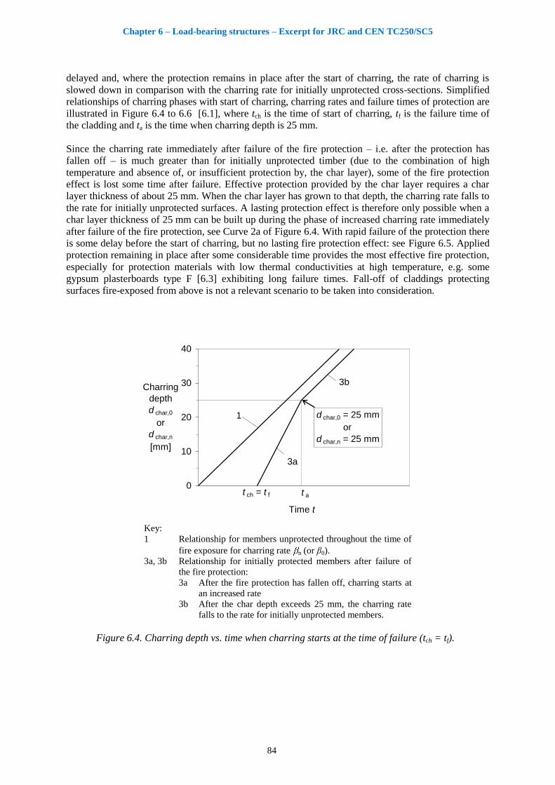
delayed and, where the protection remains in place after the start of charring, the rate of charring is
slowed down in comparison with the charring rate for initially unprotected cross-sections. Simplified
relationships of charring phases with start of charring, charring rates and failure times of protection are
illustrated in Figure 6.4 to 6.6 [6.1], where tch is the time of start of charring, tf is the failure time of
the cladding and ta is the time when charring depth is 25 mm.
Since the charring rate immediately after failure of the fire protection – i.e. after the protection has
fallen off – is much greater than for initially unprotected timber (due to the combination of high
temperature and absence of, or insufficient protection by, the char layer), some of the fire protection
effect is lost some time after failure. Effective protection provided by the char layer requires a char
layer thickness of about 25 mm. When the char layer has grown to that depth, the charring rate falls to
the rate for initially unprotected surfaces. A lasting protection effect is therefore only possible when a
char layer thickness of 25 mm can be built up during the phase of increased charring rate immediately
after failure of the fire protection, see Curve 2a of Figure 6.4. With rapid failure of the protection there
is some delay before the start of charring, but no lasting fire protection effect: see Figure 6.5. Applied
protection remaining in place after some considerable time provides the most effective fire protection,
especially for protection materials with low thermal conductivities at high temperature, e.g. some
gypsum plasterboards type F [6.3] exhibiting long failure times. Fall-off of claddings protecting
surfaces fire-exposed from above is not a relevant scenario to be taken into consideration.
0
10
20
30
40
Time t
Charring
depth
d char,0
or
d char,n
[mm]
1
3a
d char,0 = 25 mm
or
d char,n = 25 mm
3b
t a t ch = t f
Key:
1 Relationship for members unprotected throughout the time of
fire exposure for charring rate n (or β0).
3a, 3b Relationship for initially protected members after failure of
the fire protection:
3a After the fire protection has fallen off, charring starts at
an increased rate
3b After the char depth exceeds 25 mm, the charring rate
falls to the rate for initially unprotected members.
Figure 6.4. Charring depth vs. time when charring starts at the time of failure (tch = tf).

Chapter 6 – Load-bearing structures – Excerpt for JRC and CEN TC250/SC5
85
0
10
20
30
40
Time t
Charring
depth
d char,0
or
d char,n
[mm]
t f
1
3a
t a
Key:
1 Relationship for members unprotected throughout the time
of fire exposure for charring rate n (or β0).
3a Relationship for initially protected members with rapid
failure times of the fire protection tf.
Figure 6.5. Charring depth vs. time for protection with rapid failure time.
0
10
20
30
40
Time t
Charring
depth
d char,0
or
d char,n
[mm]
t ch
d char,0 = 25 mm
or
d char,n = 25 mm
1
2
t f
3a
3b
t a
Key:
1 Relationship for members unprotected throughout the time
of fire exposure for charring rate n (or β0).
2, 3a, 3b Relationship for initially protected members where charring
starts before failure of the fire protection:
2 Charring starts at tch at a reduced rate when the fire
protection is still in place
3a After the fire protection has fallen off, charring starts
at increased rate
3b After the char depth exceeds 25 mm, the charring rate
reduces to the rate for initially unprotected members.
Figure 6.6. Charring depth vs. time when charring takes place behind the fire protection (tch < tf).
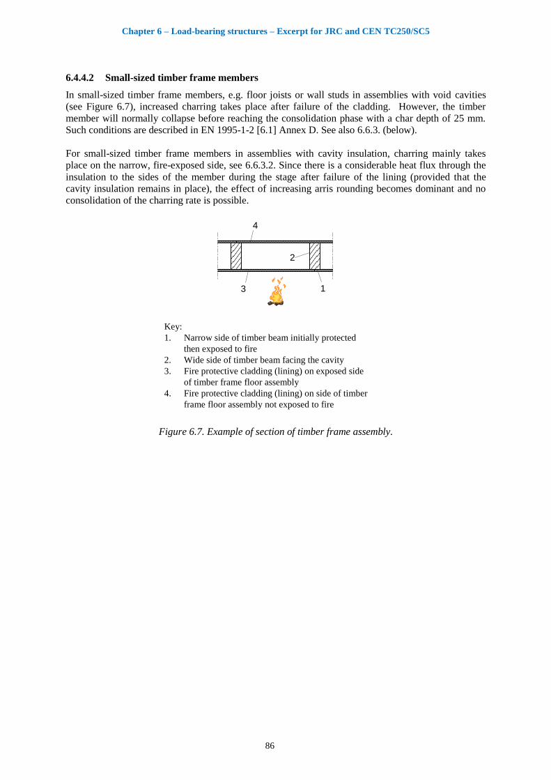
Chapter 6 – Load-bearing structures – Excerpt for JRC and CEN TC250/SC5
86
6.4.4.2 Small-sized timber frame members
In small-sized timber frame members, e.g. floor joists or wall studs in assemblies with void cavities
(see Figure 6.7), increased charring takes place after failure of the cladding. However, the timber
member will normally collapse before reaching the consolidation phase with a char depth of 25 mm.
Such conditions are described in EN 1995-1-2 [6.1] Annex D. See also 6.6.3. (below).
For small-sized timber frame members in assemblies with cavity insulation, charring mainly takes
place on the narrow, fire-exposed side, see 6.6.3.2. Since there is a considerable heat flux through the
insulation to the sides of the member during the stage after failure of the lining (provided that the
cavity insulation remains in place), the effect of increasing arris rounding becomes dominant and no
consolidation of the charring rate is possible.
2
3 1
4
Key:
1. Narrow side of timber beam initially protected
then exposed to fire
2. Wide side of timber beam facing the cavity
3. Fire protective cladding (lining) on exposed side
of timber frame floor assembly
4. Fire protective cladding (lining) on side of timber
frame floor assembly not exposed to fire
Figure 6.7. Example of section of timber frame assembly.
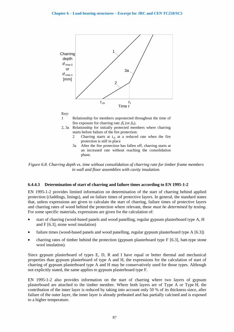
Chapter 6 – Load-bearing structures – Excerpt for JRC and CEN TC250/SC5
87
Time t
Charring
depth
d char,0
or
d char,n
[mm]
t ch
1
2
t f
3a
Key:
1 Relationship for members unprotected throughout the time of
fire exposure for charring rate n (or β0).
2, 3a Relationship for initially protected members where charring
starts before failure of the fire protection:
2 Charring starts at tch at a reduced rate when the fire
protection is still in place
3a After the fire protection has fallen off, charring starts at
an increased rate without reaching the consolidation
phase.
Figure 6.8. Charring depth vs. time without consolidation of charring rate for timber frame members
in wall and floor assemblies with cavity insulation.
6.4.4.3 Determination of start of charring and failure times according to EN 1995-1-2
EN 1995-1-2 provides limited information on determination of the start of charring behind applied
protection (claddings, linings), and on failure times of protective layers. In general, the standard states
that, unless expressions are given to calculate the start of charring, failure times of protective layers
and charring rates of wood behind the protection where relevant, these must be determined by testing.
For some specific materials, expressions are given for the calculation of:
start of charring (wood-based panels and wood panelling, regular gypsum plasterboard type A, H
and F [6.3], stone wool insulation)
failure times (wood-based panels and wood panelling, regular gypsum plasterboard type A [6.3])
charring rates of timber behind the protection (gypsum plasterboard type F [6.3], batt-type stone
wool insulation).
Since gypsum plasterboard of types E, D, R and I have equal or better thermal and mechanical
properties than gypsum plasterboard of type A and H, the expressions for the calculation of start of
charring of gypsum plasterboard type A and H may be conservatively used for those types. Although
not explicitly stated, the same applies to gypsum plasterboard type F.
EN 1995-1-2 also provides information on the start of charring where two layers of gypsum
plasterboard are attached to the timber member. Where both layers are of Type A or Type H, the
contribution of the inner layer is reduced by taking into account only 50 % of its thickness since, after
failure of the outer layer, the inner layer is already preheated and has partially calcined and is exposed
to a higher temperature.
Chapter 6 – Load-bearing structures – Excerpt for JRC and CEN TC250/SC5
88
Where two layers of different quality, e.g. Type F and Type A are attached to the timber member, it is
important that the better quality (Type F, in this example) is used as the outer layer, while the
contribution of the inner layer (Type A or H) is reduced by taking into account only 80 % of its
thickness. If the outer layer is of Type A or H, and the inner layer of Type F, it should conservatively
be assumed that both layers are of Type A or H.
Since the thermo-mechanical properties of gypsum plasterboard Type F are not part of the
classification given in [6.3], failure times of different makes may vary considerably. No generic failure
times for gypsum plasterboard are known; and so it is expected that the producer should declare failure
times determined on the basis of tests, including information on spacing of joists, studs, battens etc.
and edge distances and spacing of fasteners. Conservative values based on evaluation of a large
number of full-scale fire tests are given in 6.4.4.5. For the time being, the European system of CE-
marking does not include such information. It is important that the failure times of gypsum
plasterboard should be related to thermo-mechanical degradation of the boards, i.e. issues such as
position (horizontal or vertical), span and edge distances of fixings (screws, nails, staples). Pull-out
failure of fasteners due to charring behind the cladding should be verified by the designer; expressions
for this failure type are only given for screws: it is required that the minimum penetration length into
uncharred wood is 10 mm.
Failure times of wood-based panels and wood panelling depend on the field of application. For beams
and columns protected by these claddings, it is assumed that the cladding falls off at the time of start
of charring tch. For walls and floors, however, normally with greater distances between the fixings (the
distance on centres of supporting studs, joists or resilient channels is normally 400 to 600 mm or
more), it is assumed that the cladding falls off four minutes before the panel has burned through.
For gypsum plasterboard cladding, there is no corresponding distinction between beams and columns
on the one hand and timber frame assemblies on the other hand. More appropriate values can be
obtained from fire testing.
6.4.4.4 Start of charring and failure according to component additive method given in
Chapter 5
Differing from the components additive method given by EN 1995-1-2 [6.1][6.2], the new components
additive method presented in Section 5 is consistent with the needs of the designer to determine the
start of charring and failure times of protective layers. The method given in Section 5 is therefore
applicable and offers more precise solutions for a greater variety of materials. The start of charring can
therefore, by modification of Expression (5.4), be calculated as:
ch prot,it t (6.4)
i.e. the sum of protection times of i layers protecting the timber member, where tprot,i is calculated
according to Section 5, taking into account relevant position coefficients.
6.4.4.5 Start of charring and failure times from data base
More than 340 full-scale fire test reports with constructions including claddings made of gypsum
plasterboards in accordance with EN 520 [6.4] and gypsum fibre boards in accordance with EN
15283-2 [6.52] were evaluated. Failure times and start of charring of timber studs or joists were, when
recorded, collated in a data base [6.6]. The tested constructions were either timber frame assemblies,
the great majority with solid timber members and some with I-joists, or in a few cases lightweight
steel members. The studs or joists were placed maximum 600 mm on centres. Below pessimized
expressions are given which give conservative results, see Table 6.1 and Table 6.2. The spread of data
in the data base may be due to one or several of the following:

Chapter 6 – Load-bearing structures – Excerpt for JRC and CEN TC250/SC5
89
Variation of mechanical properties (between manufacturers or batches);
Variation of thermal properties;
Insulated or void cavity behind cladding;
Timber or steel studs;
Fixing of boards with respect to edge distance and spacing;
Fixing of boards with respect screw length;
Distance between battens or resilient steel channels fixed to floor joists.
In some tests, premature failure of the claddings may have been caused by too short screws leading to
fall-off of boards due to pull-out failure rather than thermal degradation of the boards.
The failure times of gypsum plasterboards attached to large timber members such as glued-laminated
beams and columns or solid wood panels such as CLT may be considerably greater, especially when
edge distances of screws are greater than possible in timber frame construction.
Since the values given in the tables are conservative, especially with regard to failure times, tf,
producers may wish to determine values for their products and applications to be used by designers,
see 6.4.4.3.
Table 6.1. Start of charring behind gypsum plasterboards tch in minutes with outer board thickness hp
and total board thickness hp,tot in millimetres.
Cladding Walls Floors
Type A, F one layer
p1,8 7h 9 mm ≤ hp ≤ 18 mm p1,8 7h 9 mm ≤ hp ≤ 18 mm
25,5 hp > 18 mm 25,5 hp > 18 mm
Type F two layers Type F +Type A two layers
p,tot
p
2,1 7min
3,5 7
h
h
(6.5)
25 mm ≤ hp,tot ≤ 31 mm 9 mm ≤ hp ≤ 18 mm
p,tot
p
2,1 7min
4 14
h
h
(6.6)
25 mm ≤ hp,tot ≤ 31 mm 9 mm ≤ hp ≤ 18 mm
Type A two layers
p,tot
p
2,1 7min
1,6 13
h
h
(6.7)
18 mm ≤ hp,tot ≤ 31 mm 9 mm ≤ hp ≤ 18 mm
p,tot
p
2,1 7min
1,6 11
h
h
(6.8)
18 mm ≤ hp,tot ≤ 31 mm 9 mm ≤ hp ≤ 18 mm
Note: These values may be in conflict with EN 1995-1-2 [6.1].
For structures with claddings of two layers the important issue is the fall-off of outer layer. If charring
behind the second layer starts before first layer has fallen off, the expressions for gypsum
plasterboards type F and type A are similar.
If the charring starts after the outer layer has fallen off, then the expression for start of charring time
depends on the failure time of outer layer.
Tables 6.1 and 6.2 show the safe design equations and their associated limitations of use. The
limitations come from the available test data. No extrapolation is used. In some cases the limitations
can result with bigger start of charring time compare to failure time of the same cladding. In this case
the start time of charring should be taken equal to failure time of cladding, according to Figure 6.4.

Chapter 6 – Load-bearing structures – Excerpt for JRC and CEN TC250/SC5
90
Table 6.2. Failure times of gypsum plasterboards tf in minutes with board thickness hp and total board
thickness hp,tot in millimetres.
Cladding Walls Floors
Type F, one layer
p4,5 24h
(6.9) 9 mm ≤ hp ≤ 18 mm p 10h
(6.10) 12,5 mm ≤ hp ≤ 16 mm
57 hp > 18 mm 26 hp > 16 mm
Type F, two layers
p,tot4 40h
(6.11) 25 mm ≤ hp,tot ≤ 31 mm p,tot2 3h
(6.12) 25 mm ≤ hp,tot ≤ 31 mm
84 hp,tot ≥ 31 mm 59 hp,tot ≥ 31 mm
Type F + Type A
a
81 hp ≥ 15 mm
b
hp,tot ≥ 27 mm 50 hp ≥ 15 mm
b
Type A, one layer
p1,9 7h
(6.13) 9 mm ≤ hp ≤ 15 mm p1,8 7h
(6.14) 12,5 mm ≤ hp ≤ 15 mm
21,5 hp > 15 mm 20 hp > 15 mm
Type A, two layers
p,tot2,1 14h c
(6.15) 25 mm ≤ hp,tot ≤ 30 mm
49 hp,tot ≥ 30 mm
Type A, three layers
55 hp,tot ≥ 37,5 mm –d
GF, one layer
p2,4 4h
(6.16) 10 mm ≤ hp ≤ 12,5 mm –
d
a Outer layer Type F, inner layer type A
b Thickness of first layer (Type F) c Same as EN 1995-1-2 Clause 3.4.3.3(3) d No data available.
6.4.4.5.1 Worked example: Calculation of start of charring of timber stud
21 3
Key:
1 Solid timber stud
2 12 mm OSB
3 15 mm gypsum plasterboard Type F
Figure 6.9. Timber frame wall assembly.
a. Calculation in accordance with EN 1995-1-2 [6.1]
Material properties for gypsum plasterboard Type F:
Since no failure times of gypsum plasterboard Type F are given in EN 1995-1-2 [6.1], they must be
determined by testing, see [6.1] 3.4.3.1(2). The value of failure time of gypsum plasterboard Type F
attached to floors given by the producer is tf = 65 minutes.
Material properties for OSB: ρk = 550 N/mm2 in accordance with EN 12369-1 [6.14].
Below, following Expressions of EN 1995-1-2 [6.1] are applied: (3.4), (3.5), (3.6), (3.7) and (3.11).
Start of charring of OSB:
ch p2,8 14 2,8 15 14 28 mint h
Charring rate of unprotected OSB with β0 = 0,9 mm/min from Table 3.1 in [6.1]:
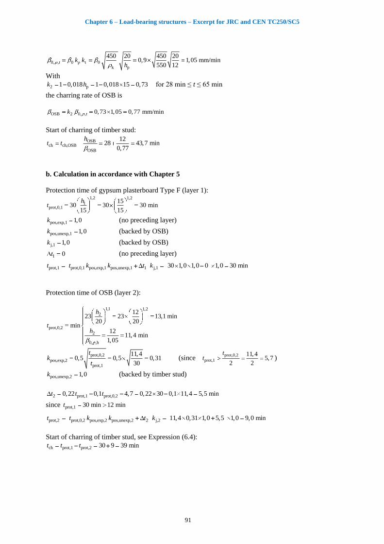
Chapter 6 – Load-bearing structures – Excerpt for JRC and CEN TC250/SC5
91
0, , 0 ρ t 0k p
450 20 450 200,9 1,05 mm/min
550 12t k k
h
With
2 p1 0,018 1 0,018 15 0,73k h for 28 min ≤ t ≤ 65 min
the charring rate of OSB is
OSB 2 0, , 0,73 1,05 0,77 mm/mintk
Start of charring of timber stud:
OSBch ch,OSB
OSB
1228 43,7 min
0,77
ht t
b. Calculation in accordance with Chapter 5
Protection time of gypsum plasterboard Type F (layer 1): 1,2 1,2
1prot,0,1
1530 30 30 min
15 15
ht
pos,exp,1 1,0k (no preceding layer)
pos,unexp,1 1,0k (backed by OSB)
j,1 1,0k (backed by OSB)
1 0t (no preceding layer)
prot,1 prot,0,1 pos,exp,1 pos,unexp,1 1 j,1 30 1,0 1,0 0 1,0 30 mint t k k t k
Protection time of OSB (layer 2):
1,1 1,2
2
prot,0,2
2
0, ,h
1223 23 13,1 min
20 20min
1211,4 min
1,05
h
th
prot,0,2
pos,exp,2prot,1
11,40,5 0,5 0,31
30
tk
t (since
prot,0,2
prot,1
11,45,7
2 2
tt )
pos,unexp,2 1,0k (backed by timber stud)
2 prot,1 prot,0,20,22 0,1 4,7 0,22 30 0,1 11,4 5,5 mint t t
since prot,1 30 min 12 mint
prot,2 prot,0,2 pos,exp,2 pos,unexp,2 2 j,2 11,4 0,31 1,0 5,5 1,0 9,0 mint t k k t k
Start of charring of timber stud, see Expression (6.4):
ch prot,1 prot,2 30 9 39 mint t t
Chapter 6 – Load-bearing structures – Excerpt for JRC and CEN TC250/SC5
92
6.4.5 Effect of bonded joints
An experimental investigation on small-scale cross-laminated timber panels tested as horizontal
elements (i.e. slab elements) showed the effect of local char ablation after the char front has reached
the bondline [6.15]. Since the char layer provides effective protection of the residual cross-
section against heat, this ablative behaviour of the char layer has the same effect as failure of
a fire protective panel, see Figure 6.4 and 6.5. Therefore it is recommended to use an increased
charring-rate in case the aforementioned effect of local char ablation is expected to occur. Additional
investigations are ongoing in order to further study the effect of local char ablation. For unprotected
cross-laminated timber (CLT) the effect observed in [6.15] is illustrated in 6.6.2.4.4. For CLT
protected by a fire protective cladding such as gypsum plasterboard Type F, the char layer remains in
place during the protection phase until failure of the fire protective cladding. However, local char
ablation may take place after the fire protective cladding has fallen off. Since fire protective claddings
delay the start of charring and reduce the charring rate, the effect of char ablation is very small. This is
illustrated in 6.6.2.4.5. In the case of vertical structural members (i.e. walls) a less pronounced char
ablation is expected and therefore this effect can be disregarded.
No observations are known about similar effects in glued-laminated timber. Since lamination
thicknesses are considerably greater than in CLT, burn-through of the outer lamellae does normally
not occur, or takes place at a very late stage. It is therefore recommended to disregard this effect.
6.5 Mechanical resistance
6.5.1 Simplified methods for strength and stiffness parameters
Since a limited zone immediately below the char-line of the residual cross-section, although unburned,
is heated above normal temperature, strength and modulus of elasticity in this zone are reduced.
Therefore, for structural fire design, the strength and stiffness parameters of the timber must be
reduced as shown below. For unprotected cross sections the heat affected zone is about 35 to 40 mm.
In general, EN 1995-1-2 [6.1] gives the design strength of timber members as
20d,fi mod,fi
M,fi
ff k (6.17)
With
20 k fif f k (6.18)
we get
kd,fi mod,fi fi
M,fi
ff k k (6.19)
where
fd,fi is the strength property in the fire situation, e.g. bending strength;
f20 is the 20 % fractile of the strength property;
fk is the characteristic strength property, e.g. as given for the strength classes in accordance with
EN 338 [6.18];
kmod,fi is the modification factor for fire expressing the reduction of strength in the fire situation;
M,fi is the partial safety factor for timber in fire.

Chapter 6 – Load-bearing structures – Excerpt for JRC and CEN TC250/SC5
93
The recommended value of the partial factor for fire is 1; information on a specific national value may
be given in the National annex. Values of kfi are given in Table 2.1 of EN 1995-1-2 [6.1]; e.g. kfi =
1,25 for solid timber, kfi = 1,15 for glued laminated timber and kfi = 1,1 for LVL (although not
mentioned in EN 1995-1-2 [6.1], for cross-laminated timber, see 6.6.2.4, kfi should be taken as 1,15).
It should be noted that the modification factor kmod, reducing the design strength taking into account
the duration of load and moisture content at normal temperature, as given in EN 1995-1-1 [6.16], is
not relevant in the fire situation and therefore not included in Expression (6.17).
In the same way as for Expression (6.17), the design value of a stiffness property, i.e. the modulus of
elasticity and shear modulus, is given as
20d,fi mod,fi
M,fi
SS k (6.20)
With
20 05 fiS S k (6.21)
we get
05d,fi mod,fi fi
M,fi
SS k k (6.22)
For a linear (1st order) ultimate limit state structural analysis, it is generally assumed that the internal
force distribution is not influenced by the stiffness properties, unless the timber is combined with other
materials in statically indeterminate structures. Thus, according to EN 1995-1-1, mean values of
stiffness properties must be used for a 1st order structural analysis of a structure, where the distribution
of internal forces is not affected by the stiffness distribution within the structure. For a non-linear (2nd
order) ultimate limit state structural analysis, stiffness properties must be taken into account in order to
assess higher order effects caused by deformation. In this case, design values of a stiffness property as
defined previously must be used. It should be noted that, contrary to EN 1995-1-1 [6.16], where the
design value of a stiffness property Ed or Gd is given by meand
M
EE and mean
d
M
GG respectively, the
above Expression (6.20) relates to the 20 % value of the stiffness property1.
For consideration of strength and stiffness reduction of members exposed on three or four sides, EN
1995-1-2 [6.1] offers two methods:
the reduced cross-section method, which is the recommended method;
the reduced properties method.
The applicable national annex may give information about the national choice. These two methods
were discussed elsewhere [6.17]. In the following only the reduced cross-section method is applied,
except for specific applications, see 6.6.3.2 and 6.6.4.
According to the reduced cross-section method, the reduction of strength and stiffness parameters is
taken into account by assuming normal temperature properties of timber multiplied by kfi. However a
zero-strength layer of depth d0 is subtracted from the residual cross-section (or, in other words, the
charring depth is increased by d0). Although, for unprotected cross sections, as much as 35 to 40 mm
1 This inconsistency is due to a late change of the final draft of [6.16] which was not taken into account
accordingly in [6.1].
Chapter 6 – Load-bearing structures – Excerpt for JRC and CEN TC250/SC5
94
below the char layer are affected by elevated temperature, the depth of the zero-strength layer is only
7 mm for normal cross-sections exposed to fire on three or four sides [6.1]. In general the zero strength
layer d0 is a function of the geometry of the cross section. For specific cross-sections and partial
protection, d0 may be considerably larger, see 6.6.2 to 6.6.5.
For calculation of the resistance of a fire-exposed member, the original cross-section is therefore
reduced by the notional charring depth and the zero-strength layer d0. The effective charring depth is
given as:
ef char,n 0 0d d k d (6.23)
where k0 takes into account the fact that the zero-strength layer is not fully effective during the first
twenty minutes of initially unprotected members, or until the start of charring of protected members.
EN 1995-1-2 [6.1] assumes linear increase from 0 to 1 during these time intervals, see [6.1] Figure 4.2.
Therefore:
0
ch
for unprotected members20
for protected members
t
kt
t
(6.24)
As a consequence, at the time of start of charring of small-sized protected cross-sections, a
considerable reduction of resistance may occur although the cross-section is still uncharred.
6.5.2 Advanced calculation methods
For determination of the mechanical resistance of structural timber members, an advanced calculation,
e.g. using finite-element modelling of fire-exposed structural timber members, comprises several
steps:
Determination of temperatures in the timber member including the charring depth
Determination of the resistance of cross-sections using the temperature field in the timber
member and the temperature-dependent reduction of strength and stiffness at each location of
the cross-section
Determination of resistance of the structure (beam, column, frame etc.)
A general outline of the procedure is given in EN 1995-1-2 [6.1], Annex B. However, for the thermal
analysis, it is the thermal properties only of wood that are given. Thermal properties for other
materials often used together with timber, e.g. gypsum plasterboard, insulation materials and others
are expected to be found in other sources. A problem is that the data from various sources may vary
considerably. Since available commercial software for heat transfer calculations does not explicitly
take into account mass transfer (water, steam, gases), its effect must be accounted for by using
effective conductivity values rather than real ones [6.19], [6.20]. This also applies to the formation of
cracks, e.g. in the char layer or gypsum plasterboards, causing increasing heat flux which is taken into
account by increased conductivity values. For the char layer, this has not been considered in some
sources, which give considerably lower conductivity values than 1995-1-2 [6.1], Annex B. Since the
protection provided by boards and insulation is often important for the performance of the timber
member, the software should be capable of taking into account sudden failure (fall-off) of applied
protection. Examples of commercial software including this option are SAFIR [6.21] and ANSYS
[6.22].
Chapter 6 – Load-bearing structures – Excerpt for JRC and CEN TC250/SC5
95
Thermal properties of gypsum plasterboard can be found in [6.23], see Table 6.3. The conductivity
values are effective values.
Table 6.3. Temperature-dependent thermal properties of gypsum plasterboard and gypsum fibreboard
[6.23].
Gypsum plasterboard Gypsum fibreboard
T
°C
λ
W/mK
c
kJ/kgK
ρ/ρ20
–
λ
W/mK
c
kJ/kgK
ρ/ρ20
–
20 0,40 0,96 100 0,40 0,96 1,00
70 0,40 0,96 100 0,40 0,96 1,00
100 0,27 0,96 100 0,27 0,96 1,00
130 0,13 14,9 92,6 0,13 9,17 0,926
140 0,13 25,2 90,2 0,13 17,55 0,902
150 0,13 21,7 87,7 0,13 16,66 0,877
170 0,13 0,96 82,8 0,13 0,96 0,828
600 0,13 0,96 82,7 0,13 0,96 0,827
720 0,33 4,36 82,6 0,39 4,359 0,826
750 0,38 0,96 77,6 0,46 0,96 0,776
1000 0,80 0,96 77,6 1,00 0,96 0,776
1200 2,37 0,96 77,6 2,37 0,96 0,776
Thermal properties of wood-based panels may be taken as follows. For particle board and wood
fibreboard, the thermal properties of wood apply. However, due to premature fall-off of charcoal, the
thermal conductivity of OSB and plywood should be taken from Table 6.4, while the properties of
wood apply to heat capacities and density ratios.
Table 6.4. Temperature-dependent thermal properties of OSB, plywood and wood fibreboard [6.23].
T
°C
λ
W/mK
20 0,12
100 0,30
110 0,23
120 0,15
200 0,18
275 0,14
350 0,09
500 023
800 0,74
1200 4,2
Thermal properties of insulation materials can be found in [6.23], see Table 6.5 and Table 6.6. For
stone wool, effective conductivity values are determined as
0
0,050
for 100 C
11e 1,9 for 100 C
T
T (6.25)
where ρ0 is given in Table 6.5.
Chapter 6 – Load-bearing structures – Excerpt for JRC and CEN TC250/SC5
96
Table 6.5. Temperature-dependent thermal properties of batt-type stone wool insulation [6.23].
T °C
λ(ρ0) W/mK
T °C
c kJ/kgK
ρ/ρ20 –
20 0,036 20 0,880 1,00
100 0,047 100 1,040 1,00
400 0,090 200 1,160 0,980
600 0,150 400 1,280 0,977
800 0,230 600 1,355 0,973
925 0,300 800 1,430 0,970
1200 0,450 925 1,477 0,960
1200 1,580 0,887
Table 6.6. Temperature-dependent thermal properties of batt-type glass wool insulation [6.23].
T
°C
λ(ρ0)
W/mK
c
kJ/kgK
ρ/ρ20
–
20 0,035 1,200 1,00
100 0,068 1,340 0,983
200 0,110 1,380 0,961
300 0,151 1,382 0,940
400 0,192 1,384 0,940
510 0,238 1,386 0,940
660 0,300 1,389 0,940
1200 100 1,400 0,940
For calculation of mechanical resistance, EN 1995-1-2 [6.1], Annex B gives temperature-dependent
reduction factors kΘ for compressive, tensile and shear strength as well as for the modulus of elasticity
parallel to the grain for timber. The reduction factor kΘ should not be confused with the modification
factor for fire, kmod,fi, see 6.5.1, which gives the reduction of a strength or stiffness property with the
assumption of a linear relationship between stress and strain ([6.16] Clause 3.1.2).
Note: The reduction of strength properties given in EN 1995-1-2 [6.1] may appear be in conflict with EN 1995-
1-1 [6.16] which is valid for temperatures not greater than 60°C. As above, the strength properties given in EN
1995-1-2 Annex B are local properties and include the effect of moisture. Timber members exposed to long-term
elevated temperatures up to 60°C would dry out causing increased strength properties. A reduction of the
modification factor under ambient conditions up to 60°C, kmod, is therefore not necessary, see also the test results
given in [6.24].
For timber members, it is sufficient to assume ideal elastic-plastic behaviour for compression and
purely elastic behaviour for tension, see Figure 6.10, relationship for 20°C. The figure also shows the
corresponding relationships for some other temperatures obtained by multiplication by kΘ.
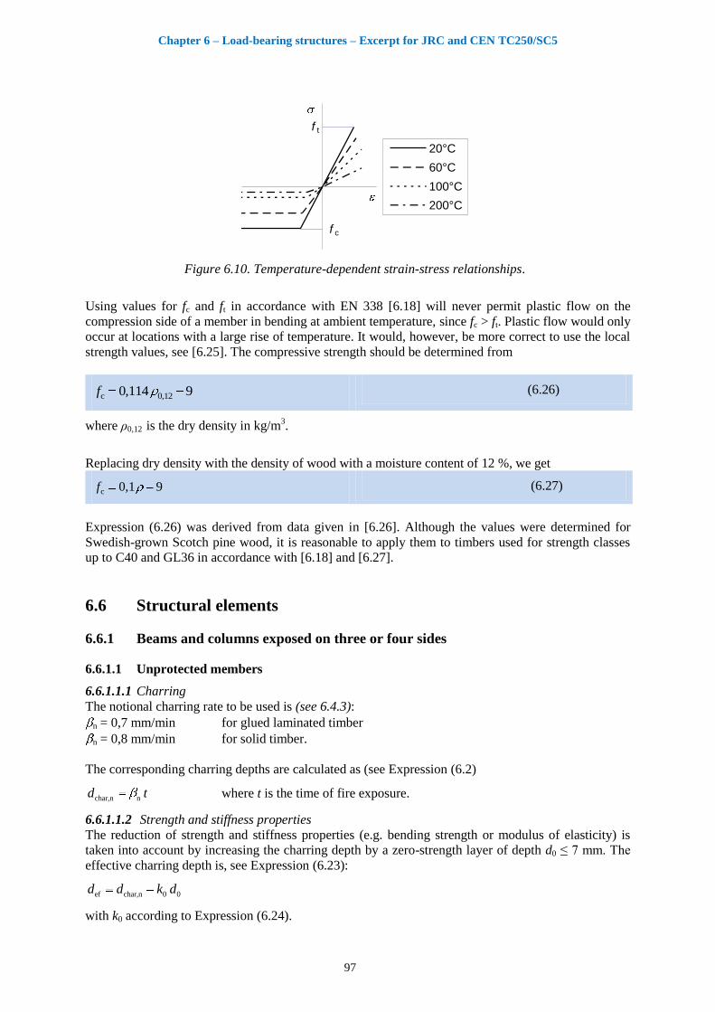
Chapter 6 – Load-bearing structures – Excerpt for JRC and CEN TC250/SC5
97
20°C
60°C
100°C
200°C
f t
f c
Figure 6.10. Temperature-dependent strain-stress relationships.
Using values for fc and ft in accordance with EN 338 [6.18] will never permit plastic flow on the
compression side of a member in bending at ambient temperature, since fc > ft. Plastic flow would only
occur at locations with a large rise of temperature. It would, however, be more correct to use the local
strength values, see [6.25]. The compressive strength should be determined from
c 0,120,114 9f (6.26)
where ρ0,12 is the dry density in kg/m
3.
Replacing dry density with the density of wood with a moisture content of 12 %, we get
c 0,1 9f (6.27)
Expression (6.26) was derived from data given in [6.26]. Although the values were determined for
Swedish-grown Scotch pine wood, it is reasonable to apply them to timbers used for strength classes
up to C40 and GL36 in accordance with [6.18] and [6.27].
6.6 Structural elements
6.6.1 Beams and columns exposed on three or four sides
6.6.1.1 Unprotected members
6.6.1.1.1 Charring
The notional charring rate to be used is (see 6.4.3):
n = 0,7 mm/min for glued laminated timber
n = 0,8 mm/min for solid timber.
The corresponding charring depths are calculated as (see Expression (6.2)
char,n nd t
where t is the time of fire exposure.
6.6.1.1.2 Strength and stiffness properties
The reduction of strength and stiffness properties (e.g. bending strength or modulus of elasticity) is
taken into account by increasing the charring depth by a zero-strength layer of depth d0 ≤ 7 mm. The
effective charring depth is, see Expression (6.23):
ef char,n 0 0d d k d
with k0 according to Expression (6.24).
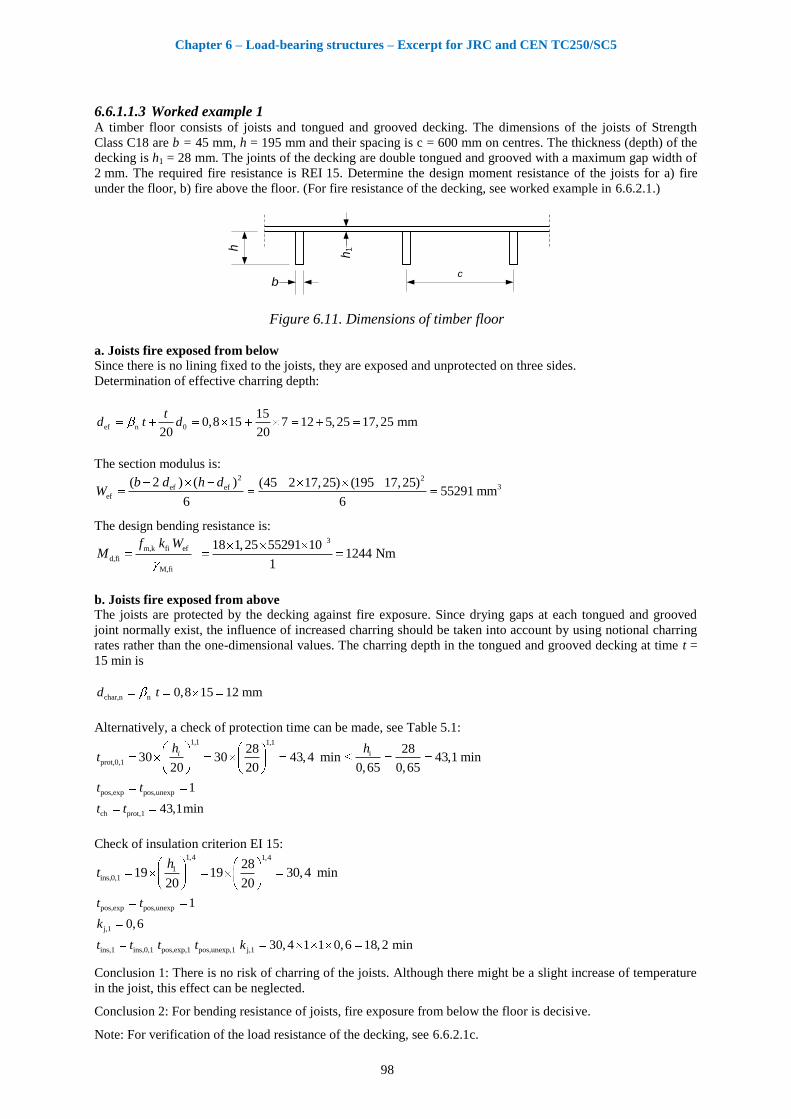
Chapter 6 – Load-bearing structures – Excerpt for JRC and CEN TC250/SC5
98
6.6.1.1.3 Worked example 1 A timber floor consists of joists and tongued and grooved decking. The dimensions of the joists of Strength
Class C18 are b = 45 mm, h = 195 mm and their spacing is c = 600 mm on centres. The thickness (depth) of the
decking is h1 = 28 mm. The joints of the decking are double tongued and grooved with a maximum gap width of
2 mm. The required fire resistance is REI 15. Determine the design moment resistance of the joists for a) fire
under the floor, b) fire above the floor. (For fire resistance of the decking, see worked example in 6.6.2.1.)
b
h
h1
c
Figure 6.11. Dimensions of timber floor
a. Joists fire exposed from below
Since there is no lining fixed to the joists, they are exposed and unprotected on three sides.
Determination of effective charring depth:
ef n 0
150,8 15 7 12 5,25 17,25 mm
20 20
td t d
The section modulus is: 2 2
3ef ef
ef
( 2 ) ( ) (45 2 17,25) (195 17,25)55291 mm
6 6
b d h dW
The design bending resistance is: 3
m,k fi ef
d,fi
M,fi
18 1,25 55291 101244 Nm
1
f k WM
b. Joists fire exposed from above
The joists are protected by the decking against fire exposure. Since drying gaps at each tongued and grooved
joint normally exist, the influence of increased charring should be taken into account by using notional charring
rates rather than the one-dimensional values. The charring depth in the tongued and grooved decking at time t =
15 min is
char,n n 0,8 15 12 mmd t
Alternatively, a check of protection time can be made, see Table 5.1: 1,1 1,1
i
prot,0,1
28 2830 30 43,4 min 43,1 min
20 20 0,65 0,65
ih ht
pos,exp pos,unexp 1t t
ch prot,1 43,1mint t
Check of insulation criterion EI 15: 1,4 1,4
1
ins,0,1
2819 19 30,4 min
20 20
ht
pos,exp pos,unexp 1t t
j,1 0,6k
ins,1 ins,0,1 pos,exp,1 pos,unexp,1 j,1 30,4 1 1 0,6 18,2 mint t t t k
Conclusion 1: There is no risk of charring of the joists. Although there might be a slight increase of temperature
in the joist, this effect can be neglected.
Conclusion 2: For bending resistance of joists, fire exposure from below the floor is decisive.
Note: For verification of the load resistance of the decking, see 6.6.2.1c.
Chapter 6 – Load-bearing structures – Excerpt for JRC and CEN TC250/SC5
99
6.6.2 Solid timber decks and walls
6.6.2.1 Tongued and grooved timber decking
6.6.2.1.1 Charring
Unlike the constructions shown in the following subclauses, a tongued and grooved timber deck is
normally supported by a number of timber frame joists. EN 1995-1-2 [6.1] gives no specific
information on charring rates of tongue and groove timber decking. Since timber decking is load-
bearing, charring rates should be taken from Table 3.1 in [6.1] Rows a to c, but not d (wood
panelling). Since drying gaps normally exist at each joint, the influence of increased charring should
be taken into account by using notional charring rates, given in Table 3.1 in [6.1], rather than the one-
dimensional values. Since tongued and grooved joints are “weak zones” with respect to heat transfer,
the protection time tprot for determination of burn-through time should be determined and be multiplied
by the joint coefficient kj, see Table 5.5.
6.6.2.1.2 Strength and stiffness properties
The reduction of strength and stiffness properties (e.g. bending strength or modulus of elasticity) is
taken into account by increasing the charring depth by a zero-strength layer of depth d0. It has been
shown [6.28] that d0 for timber deck plates may be greater than 7 mm. For plate thicknesses of up to
35 mm, 0 7 mmd should be a reasonable value. Therefore (see Expression (6.23))
ef char,n 0 0d d k d
with k0 according to Expression (6.24).
6.6.2.1.3 Worked example See 6.6.1.1, worked example. Check mechanical resistance of decking.
a. Decking exposed to fire from below
Decking: C18. Dimension of planks 36 mm ×150 mm.
According to EN 1991-1-1 [6.29], the recommended actions on the floor for Category A are qk = 2 kN/m2 and
Qk = 2 kN. For local action effects, only the concentrated load needs to be taken into account, acting on a
surface area of 50 mm × 50 mm. It is assumed that the concentrated load is taken by one plank (no load
distribution to other planks).
Combination factor for quasi-permanent action: 2,1 0,3 (see EN 1991-1-1 [6.29])
Partial factor for leading variable action: Q,1 1,5 (see EN 1990 [6.31], Table A1.2(A))
Neglecting the self-weight of the decking, the design action in the fire situation is:
d,fi fi dE E (see EN 1995-1-2 [6.1], Expression (2.8))
2,1k k,1
fiG k Q,1 k,1
0 0,3 20, 2
0 1,5 2
G Q
G Q (see EN 1995-1-2 [6.1], Expression (2.9))
Design value of action at normal temperature: d Q k 1,5 2 3 kNQ Q
Maximum bending moment: d,fi d fi0,175 0,175 3000 0,2 0,6 63 NmM Q
Since there are gaps of maximum 2 mm width in the decking, a notional charring rate of 0,8 mm/min should be
used.
Charring depth at 15 minutes: char n fi 0,8 15 12 mmd t
Effective charring depth: ef char 0 0
1512 7 17,3 mm
20d d d k
Effective deck thickness: ef ef 36 17,25 18,7 mmh h d

Chapter 6 – Load-bearing structures – Excerpt for JRC and CEN TC250/SC5
100
Neglecting the dispersion angle β = 15° of the concentrated load perpendicular to the grain (see EN 1995-2
[6.30], clause 5.2), the width of the beam under the concentrated load is 50 mm. Therefore:
Effective section modulus: 2
3ef
50 18,752930 mm
6W
Design value of maximum bending stress: d,fi 2
d,fief
6300021,5 N/mm
2930
M
W
Design value of bending strength in fire: 2m,d,fi fi m,k 1,25 18 22,5 N/mmf k f
6.6.2.2 Glued-laminated and stress-laminated timber plates
This clause deals with timber deck or wall plates made of edgewise-arranged laminations of solid
timber, held together either by adhesive bonding or by pre-stressing, see Figure 6.12.
1
Key:
1 Tendon
a. b.
Figure 6.12. Examples of deck plates: a. Glued-laminated, b. Pre-stressed.
The charring depth should be calculated in accordance with EN 1995-1-2 [6.1] Clause 3.4, using the
one-dimensional charring rate 0.
For verification of mechanical resistance, the reduced cross-section method given in EN 1995-1-2
[6.1] Clause 4.2.2 should be used, but with the values for the zero-strength layer d0 [6.28] given in
Table 6.7:
Table 6.7. Zero-strength layer d0 in mm, where h is in mm
Exposure on Floors Walls
unprotected protected unprotected protected
Tension side 8,5
55
h
(6.28)
As unprotected. –b
–b
Compression side
920
h
(6.29)
As unprotected. 9
20
h
(6.30)
As unprotected.
a Values also to be used for t > tf
b Not relevant
6.6.2.3 Nail-laminated timber plates
This clause deals with timber deck or wall plates made of edgewise-arranged laminations made of
solid timber, held together by nailing, see Figure 6.13.
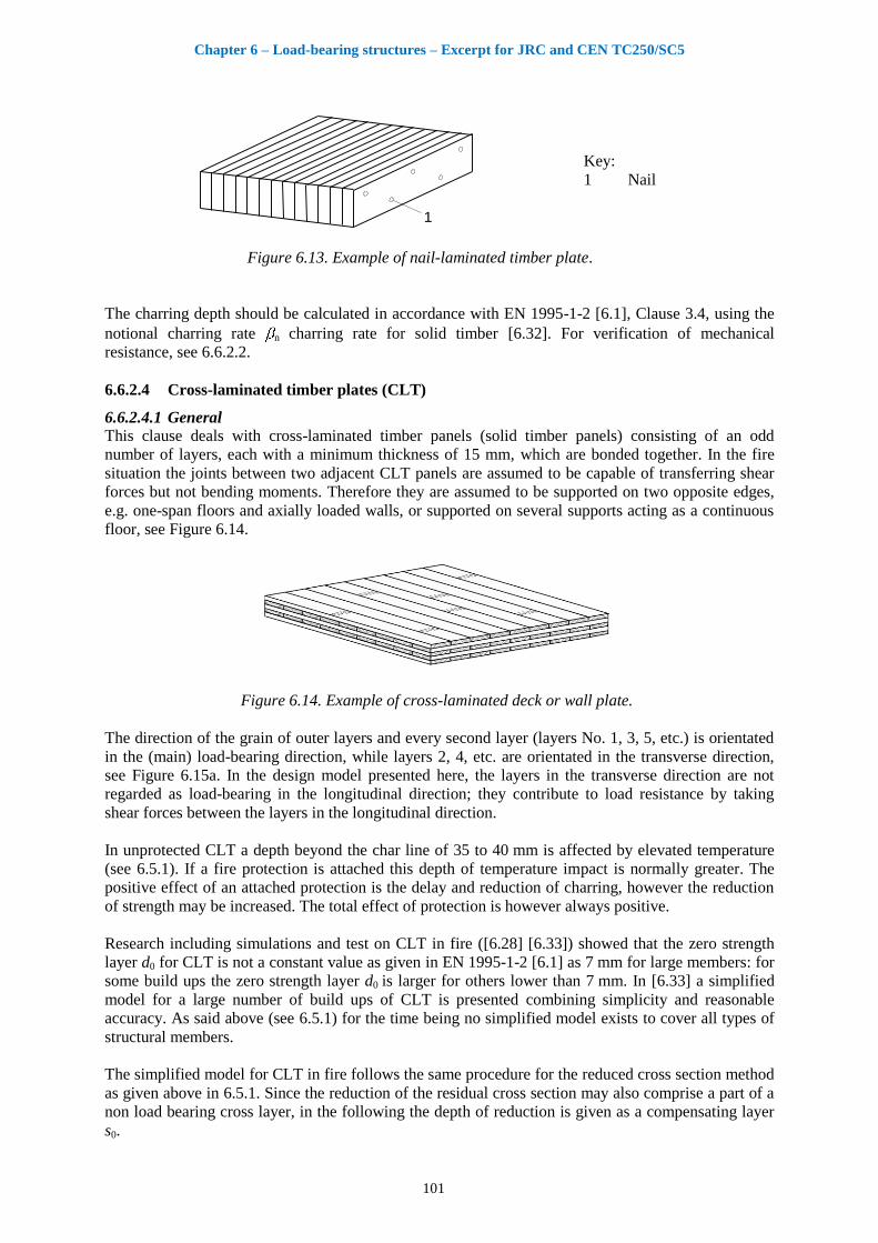
Chapter 6 – Load-bearing structures – Excerpt for JRC and CEN TC250/SC5
101
1
Key:
1 Nail
Figure 6.13. Example of nail-laminated timber plate.
The charring depth should be calculated in accordance with EN 1995-1-2 [6.1], Clause 3.4, using the
notional charring rate n charring rate for solid timber [6.32]. For verification of mechanical
resistance, see 6.6.2.2.
6.6.2.4 Cross-laminated timber plates (CLT)
6.6.2.4.1 General
This clause deals with cross-laminated timber panels (solid timber panels) consisting of an odd
number of layers, each with a minimum thickness of 15 mm, which are bonded together. In the fire
situation the joints between two adjacent CLT panels are assumed to be capable of transferring shear
forces but not bending moments. Therefore they are assumed to be supported on two opposite edges,
e.g. one-span floors and axially loaded walls, or supported on several supports acting as a continuous
floor, see Figure 6.14.
Figure 6.14. Example of cross-laminated deck or wall plate.
The direction of the grain of outer layers and every second layer (layers No. 1, 3, 5, etc.) is orientated
in the (main) load-bearing direction, while layers 2, 4, etc. are orientated in the transverse direction,
see Figure 6.15a. In the design model presented here, the layers in the transverse direction are not
regarded as load-bearing in the longitudinal direction; they contribute to load resistance by taking
shear forces between the layers in the longitudinal direction.
In unprotected CLT a depth beyond the char line of 35 to 40 mm is affected by elevated temperature
(see 6.5.1). If a fire protection is attached this depth of temperature impact is normally greater. The
positive effect of an attached protection is the delay and reduction of charring, however the reduction
of strength may be increased. The total effect of protection is however always positive.
Research including simulations and test on CLT in fire ([6.28] [6.33]) showed that the zero strength
layer d0 for CLT is not a constant value as given in EN 1995-1-2 [6.1] as 7 mm for large members: for
some build ups the zero strength layer d0 is larger for others lower than 7 mm. In [6.33] a simplified
model for a large number of build ups of CLT is presented combining simplicity and reasonable
accuracy. As said above (see 6.5.1) for the time being no simplified model exists to cover all types of
structural members.
The simplified model for CLT in fire follows the same procedure for the reduced cross section method
as given above in 6.5.1. Since the reduction of the residual cross section may also comprise a part of a
non load bearing cross layer, in the following the depth of reduction is given as a compensating layer
s0.
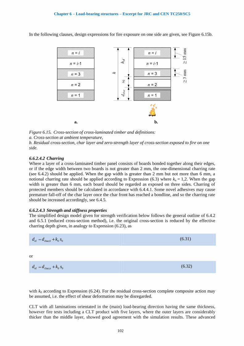
Chapter 6 – Load-bearing structures – Excerpt for JRC and CEN TC250/SC5
102
In the following clauses, design expressions for fire exposure on one side are given, see Figure 6.15b.
a. b.
Figure 6.15. Cross-section of cross-laminated timber and definitions:
a. Cross-section at ambient temperature,
b. Residual cross-section, char layer and zero-strength layer of cross-section exposed to fire on one
side.
6.6.2.4.2 Charring
Where a layer of a cross-laminated timber panel consists of boards bonded together along their edges,
or if the edge width between two boards is not greater than 2 mm, the one-dimensional charring rate
(see 6.4.2) should be applied. When the gap width is greater than 2 mm but not more than 6 mm, a
notional charring rate should be applied according to Expression (6.3) where kn = 1,2. When the gap
width is greater than 6 mm, each board should be regarded as exposed on three sides. Charring of
protected members should be calculated in accordance with 6.4.4.1. Some novel adhesives may cause
premature fall-off of the char layer once the char front has reached a bondline, and so the charring rate
should be increased accordingly, see 6.4.5.
6.6.2.4.3 Strength and stiffness properties
The simplified design model given for strength verification below follows the general outline of 6.4.2
and 6.5.1 (reduced cross-section method), i.e. the original cross-section is reduced by the effective
charring depth given, in analogy to Expression (6.23), as
ef char,0 0 0d d k s (6.31)
or
ef char,n 0 0d d k s (6.32)
with k0 according to Expression (6.24). For the residual cross-section complete composite action may
be assumed, i.e. the effect of shear deformation may be disregarded.
CLT with all laminations orientated in the (main) load-bearing direction having the same thickness,
however fire tests including a CLT product with five layers, where the outer layers are considerably
thicker than the middle layer, showed good agreement with the simulation results. These advanced
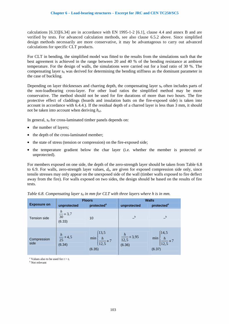
Chapter 6 – Load-bearing structures – Excerpt for JRC and CEN TC250/SC5
103
calculations [6.33][6.34] are in accordance with EN 1995-1-2 [6.1], clause 4.4 and annex B and are
verified by tests. For advanced calculation methods, see also clause 6.5.2 above. Since simplified
design methods necessarily are more conservative, it may be advantageous to carry out advanced
calculations for specific CLT products.
For CLT in bending, the simplified model was fitted to the results from the simulations such that the
best agreement is achieved in the range between 20 and 40 % of the bending resistance at ambient
temperature. For the design of walls, the simulations were carried out for a load ratio of 30 %. The
compensating layer s0 was derived for determining the bending stiffness as the dominant parameter in
the case of buckling.
Depending on layer thicknesses and charring depth, the compensating layer s0 often includes parts of
the non-loadbearing cross-layer. For other load ratios the simplified method may be more
conservative. The method should not be used for fire durations of more than two hours. The fire
protective effect of claddings (boards and insulation batts on the fire-exposed side) is taken into
account in accordance with 6.4.4.). If the residual depth of a charred layer is less than 3 mm, it should
not be taken into account when deriving hef.
In general, s0 for cross-laminated timber panels depends on:
the number of layers;
the depth of the cross-laminated member;
the state of stress (tension or compression) on the fire-exposed side;
the temperature gradient below the char layer (i.e. whether the member is protected or
unprotected).
For members exposed on one side, the depth of the zero-strength layer should be taken from Table 6.8
to 6.9. For walls, zero-strength layer values, d0, are given for exposed compression side only, since
tensile stresses may only appear on the unexposed side of the wall (timber walls exposed to fire deflect
away from the fire). For walls exposed on two sides, the design should be based on the results of fire
tests.
Table 6.8. Compensating layer s0 in mm for CLT with three layers where h is in mm.
Exposure on
Floors Walls
unprotected protecteda
unprotected protecteda
Tension side
3,730
h
(6.33)
10 –b
–b
Compression side
4,525
h
(6.34)
13,5
min7
12,5
h
(6.35)
3,9512,5
h
(6.36)
14,5
min7
12,5
h
(6.37)
a Values also to be used for t > tf b Not relevant
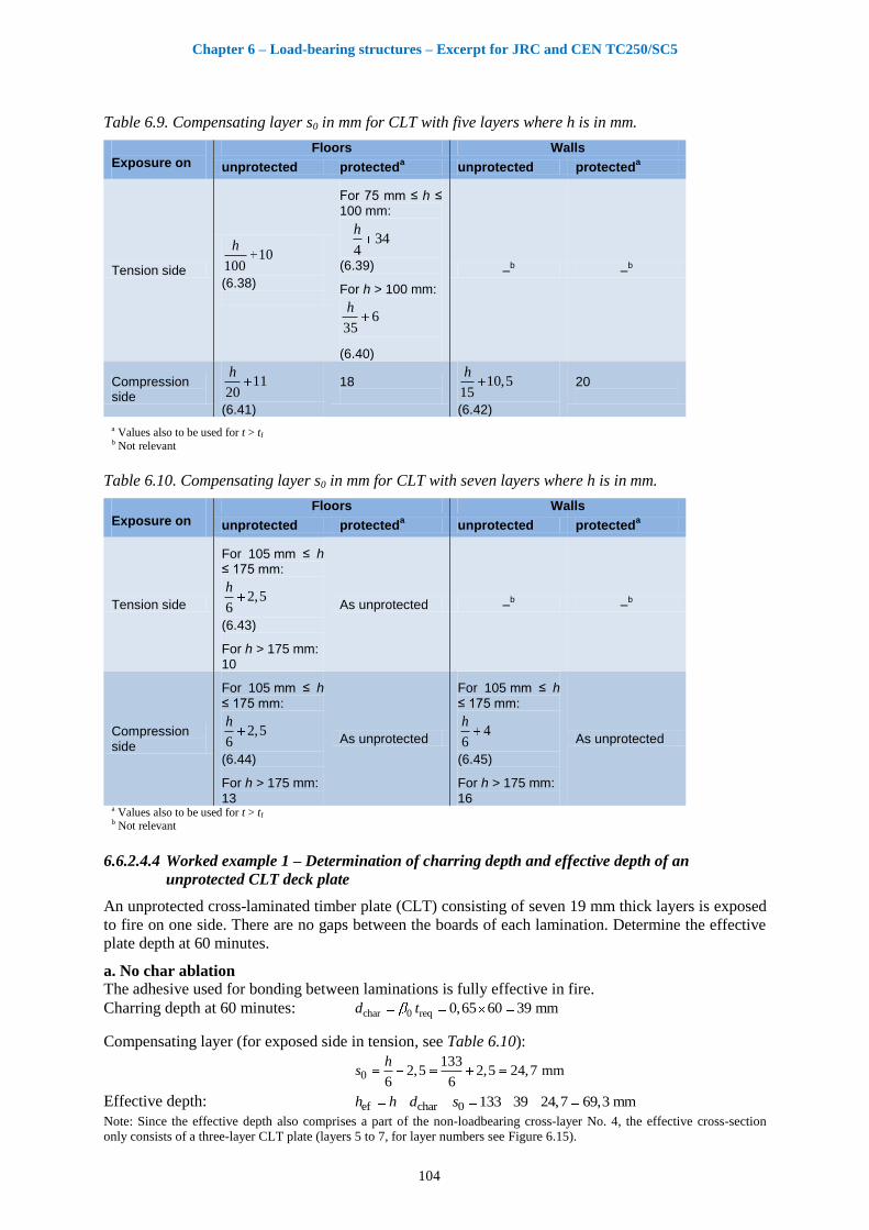
Chapter 6 – Load-bearing structures – Excerpt for JRC and CEN TC250/SC5
104
Table 6.9. Compensating layer s0 in mm for CLT with five layers where h is in mm.
Exposure on
Floors Walls
unprotected protecteda
unprotected protecteda
Tension side
10100
h
(6.38)
For 75 mm ≤ h ≤ 100 mm:
344
h
(6.39)
For h > 100 mm:
635
h
(6.40)
–b
–b
Compression side
1120
h
(6.41)
18
10,515
h
(6.42)
20
a Values also to be used for t > tf b Not relevant
Table 6.10. Compensating layer s0 in mm for CLT with seven layers where h is in mm.
Exposure on
Floors Walls
unprotected protecteda
unprotected protecteda
Tension side
For 105 mm ≤ h ≤ 175 mm:
2,56
h
(6.43)
For h > 175 mm: 10
As unprotected –b
–b
Compression side
For 105 mm ≤ h
≤ 175 mm:
2,56
h
(6.44)
For h > 175 mm:
13
As unprotected
For 105 mm ≤ h
≤ 175 mm:
46
h
(6.45)
For h > 175 mm:
16
As unprotected
a Values also to be used for t > tf b Not relevant
6.6.2.4.4 Worked example 1 – Determination of charring depth and effective depth of an
unprotected CLT deck plate
An unprotected cross-laminated timber plate (CLT) consisting of seven 19 mm thick layers is exposed
to fire on one side. There are no gaps between the boards of each lamination. Determine the effective
plate depth at 60 minutes.
a. No char ablation
The adhesive used for bonding between laminations is fully effective in fire.
Charring depth at 60 minutes: char 0 req 0,65 60 39 mmd t
Compensating layer (for exposed side in tension, see Table 6.10):
0133
2,5 2,5 24,7 mm6 6
hs
Effective depth: ef char 0 133 39 24,7 69,3 mmh h d s Note: Since the effective depth also comprises a part of the non-loadbearing cross-layer No. 4, the effective cross-section
only consists of a three-layer CLT plate (layers 5 to 7, for layer numbers see Figure 6.15).
Chapter 6 – Load-bearing structures – Excerpt for JRC and CEN TC250/SC5
105
b. Calculation with ablation of char layer (see 6.4.5)
The failure time of Layer 1 is equal to the start of charring of Layer 2:
1ch f,1
0
1929,2 min
0,65
ht t
Charring depth at 60 minutes:
char 1 req f 0 3 19 60 29,2 0,65 2 59 mmd h t t k
Compensating layer as above: 0 24,7 mms
Effective depth: ef char 0 133 59,2 24,7 49,1 mmh h d s
6.6.2.4.5 Worked example 2 – Determination of charring depth and effective depth of a protected
CLT deck plate
The same CLT as above in 6.6.2.4.4 is protected by a 12,5 mm thick layer of Type F gypsum
plasterboard. Determine the charring depth at 60 minutes. The failure time of Type F gypsum
plasterboard is given by the producer as tf = 45 minutes.
a. No char ablation
The adhesive used for bonding between laminations is fully effective in fire.
Start of charring:
ch p2,8 14 2,8 12,5 14 21 mint h
Protection factor according to EN 1995-1-2 [6.1] Expression (3.7):
2 p1 0,018 1 0,018 12,5 0,775k h
Post-protection factor according to EN 1995-1-2 [6.1] Paragraph 3.4.3.2(4): 3 2k
Calculation of ta according to EN 1995-1-2 [6.1] Expression (3.9), see Figure 6.6:
f ch 2 0a f
3 0
25 25 45 21 0,775 0,6545 54,9 min
2 0,65
t t kt t
k
Charring depth at 60 minutes:
char req a 025 25 60 54,9 0,65 28,3 mmd t t
Compensating layer as above: 0133
2,5 2,5 24,7 mm6 6
hs
Effective depth: ef char 0 133 28,3 24,7 80 mmh h d s Effective thickness of layer 3: 5,ef 80 4 19 4 3 mmh
(For layer numbering, see Figure 6.15)
b. Calculation with ablation of char layer (see 6.4.5)
Charring depth at time of failure (tf = 45 min):
char,f f ch 0 2 45 21 0,65 0,775 12,1 mmd t t k
Since the char layer falls off the CLT-plate before the charring depth is equal to 25 mm, no value of ta
exists, i.e. charring continues at a rate of k3 0.
Charring depth at 60 minutes:
char char,f req f 3 0 12,1 60 45 31,6 mmd d t t k
Compensating layer as above: 0 24,7 mms
Effective depth: ef char 0 133 31,6 24,7 76,7 mmh h d s Effective thickness of layer 3: 5,ef 76,7 4 19 0,7 3 mmh
Since the effective depth of layer 3 is smaller than 3 mm, this layer does not contribute to bending
resistance.
Chapter 6 – Load-bearing structures – Excerpt for JRC and CEN TC250/SC5
106
6.6.3 Timber frame floor and wall assemblies
6.6.3.1 General
Timber frame assemblies are normally built up of the timber frame (floor joists or wall studs) and a
cladding attached to each side of the timber frame (the cladding may be a lining or, in the case of
floors, the decking or a sub-floor and additional layers). The cavities may be void or partially or
completely filled with insulation. Since the timber frame is sensitive to fire exposure, it must be
effectively protected against fire.
In the design and optimisation of a timber frame assembly, the following rules are important with
respect to maximising fire resistance,:
There exists a hierarchy of contribution to fire resistance of various layers of the assembly;
The greatest contribution to fire resistance is obtained from the membrane (layer) on the fire-
exposed side first directly exposed to the fire, both with respect to insulation and failure (fall-off)
of the membrane.
In general, it is difficult to compensate for poor fire protection performance of the first membrane
by improved fire protection performance of the following layers.
Cavity insulation improves the fire resistance of the timber frame. The best protection against fire
is achieved when the insulation effectively protects the sides of the timber member facing the
cavity against the fire.
For the stage before failure of the cladding (protection phase t ≤ tf), or, more precisely, failure of the
layer of the cladding next to the insulation, both batt-type and loose-fill mineral wool (stone or glass
wool) insulation perform approximately equally. However, once the cladding has fallen off and the
insulation is directly exposed to the fire (post-protection phase t ≥ tf), glass wool insulation will
undergo decomposition, gradually losing its protecting effect for the timber member by surface
recession. Stone wool insulation, provided that it remains in place, will continue to protect the sides of
the timber member facing the cavity. During this post-protection stage, loose-fill insulation should not
be used. Batt-type mineral wool insulation should always be secured mechanically, e.g. by resilient
steel channels or battens. The steel channels must be fixed with screws of sufficient length to prevent
pull-out failure due to extensive charring of the joists. In the case of wall assemblies, mineral wool
batts are normally fixed by oversizing the width of the batts. When the thickness of the batts is
insufficient, they tend prematurely to fall off a wall assembly; and so batts less than 120 mm thick
should be mechanically secured, e.g. by wires or chicken net fixed to the studs, with the wires or
chicken net in turn being secured by staples of sufficient length to prevent pull-out failure due to
extensive charring of the studs.
The design model presented in 6.6.3.2 is valid for cavities filled with stone wool. Where glass wool is
used, the model is valid until failure (fall-off) of the cladding. Immediate failure of the assembly is a
conservative assumption. From full-scale wall tests, it is known that it will take some time until the
glass wool insulation has completely recessed once it has been directly exposed to the fire. A model of
cavities filled with batt-type glass wool insulation has been developed, describing the surface
recession of the glass wool insulation [6.35]. A new design model for the post-protection stage of
assemblies with glass wool cavity insulation can be found in 6.6.3.4.
Where the wall is placed between two floors (platform frame construction), each providing a
horizontal support, it may be advantageous to take into account partial restraint at the supports for the
calculation of the axial load capacity of the wall with respect to buckling of the studs perpendicular to
the wall. The partial restraint is due to the movement of the reaction forces towards the unexposed
edge of a stud as its ends rotate, thus reducing the eccentricity of the axial loading. This positive effect
was studied in [6.36] and may be taken into account assuming a buckling length of
y wall0,7
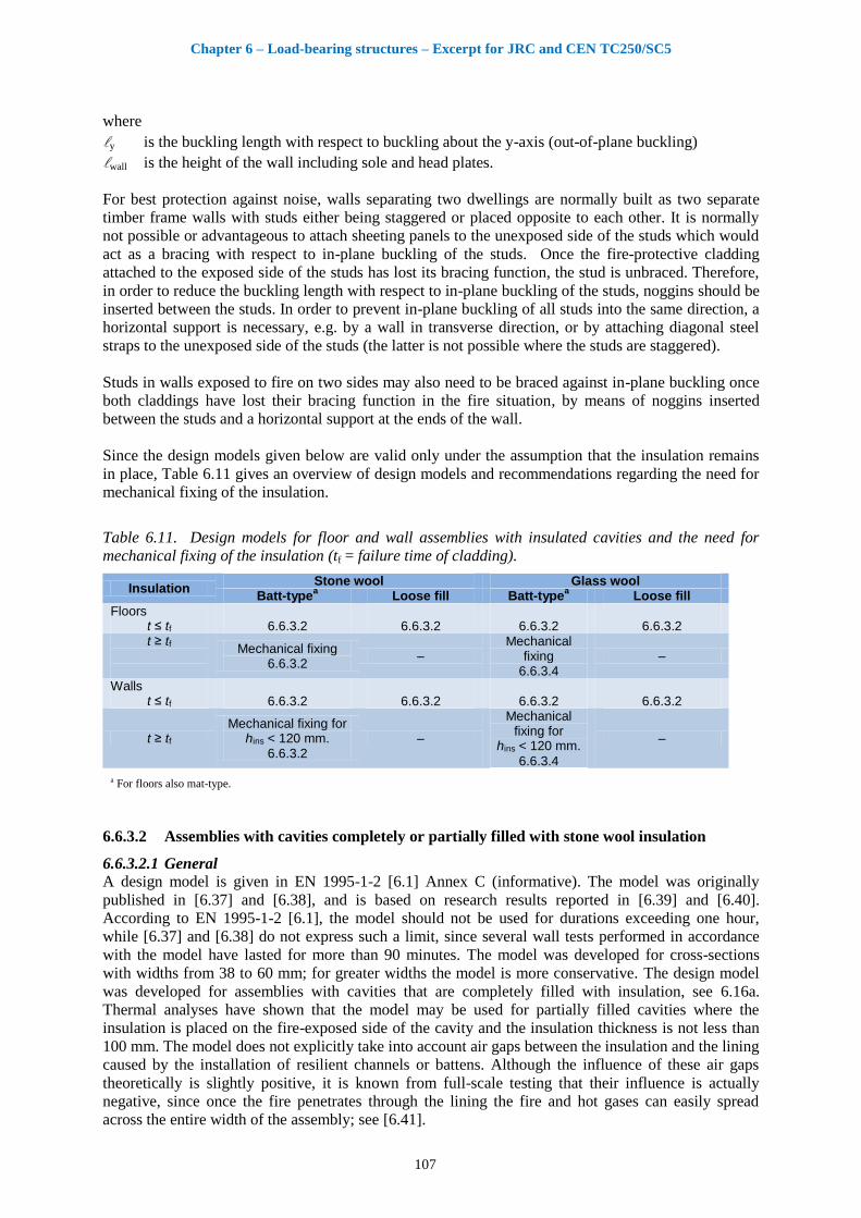
Chapter 6 – Load-bearing structures – Excerpt for JRC and CEN TC250/SC5
107
where
y is the buckling length with respect to buckling about the y-axis (out-of-plane buckling)
wall is the height of the wall including sole and head plates.
For best protection against noise, walls separating two dwellings are normally built as two separate
timber frame walls with studs either being staggered or placed opposite to each other. It is normally
not possible or advantageous to attach sheeting panels to the unexposed side of the studs which would
act as a bracing with respect to in-plane buckling of the studs. Once the fire-protective cladding
attached to the exposed side of the studs has lost its bracing function, the stud is unbraced. Therefore,
in order to reduce the buckling length with respect to in-plane buckling of the studs, noggins should be
inserted between the studs. In order to prevent in-plane buckling of all studs into the same direction, a
horizontal support is necessary, e.g. by a wall in transverse direction, or by attaching diagonal steel
straps to the unexposed side of the studs (the latter is not possible where the studs are staggered).
Studs in walls exposed to fire on two sides may also need to be braced against in-plane buckling once
both claddings have lost their bracing function in the fire situation, by means of noggins inserted
between the studs and a horizontal support at the ends of the wall.
Since the design models given below are valid only under the assumption that the insulation remains
in place, Table 6.11 gives an overview of design models and recommendations regarding the need for
mechanical fixing of the insulation.
Table 6.11. Design models for floor and wall assemblies with insulated cavities and the need for
mechanical fixing of the insulation (tf = failure time of cladding).
Insulation Stone wool Glass wool
Batt-typea
Loose fill Batt-typea
Loose fill
Floors t ≤ tf 6.6.3.2 6.6.3.2 6.6.3.2 6.6.3.2 t ≥ tf
Mechanical fixing 6.6.3.2
– Mechanical
fixing 6.6.3.4
–
Walls t ≤ tf 6.6.3.2 6.6.3.2 6.6.3.2 6.6.3.2
t ≥ tf
Mechanical fixing for hins < 120 mm.
6.6.3.2 –
Mechanical fixing for
hins < 120 mm.
6.6.3.4
–
a For floors also mat-type.
6.6.3.2 Assemblies with cavities completely or partially filled with stone wool insulation
6.6.3.2.1 General
A design model is given in EN 1995-1-2 [6.1] Annex C (informative). The model was originally
published in [6.37] and [6.38], and is based on research results reported in [6.39] and [6.40].
According to EN 1995-1-2 [6.1], the model should not be used for durations exceeding one hour,
while [6.37] and [6.38] do not express such a limit, since several wall tests performed in accordance
with the model have lasted for more than 90 minutes. The model was developed for cross-sections
with widths from 38 to 60 mm; for greater widths the model is more conservative. The design model
was developed for assemblies with cavities that are completely filled with insulation, see 6.16a.
Thermal analyses have shown that the model may be used for partially filled cavities where the
insulation is placed on the fire-exposed side of the cavity and the insulation thickness is not less than
100 mm. The model does not explicitly take into account air gaps between the insulation and the lining
caused by the installation of resilient channels or battens. Although the influence of these air gaps
theoretically is slightly positive, it is known from full-scale testing that their influence is actually
negative, since once the fire penetrates through the lining the fire and hot gases can easily spread
across the entire width of the assembly; see [6.41].
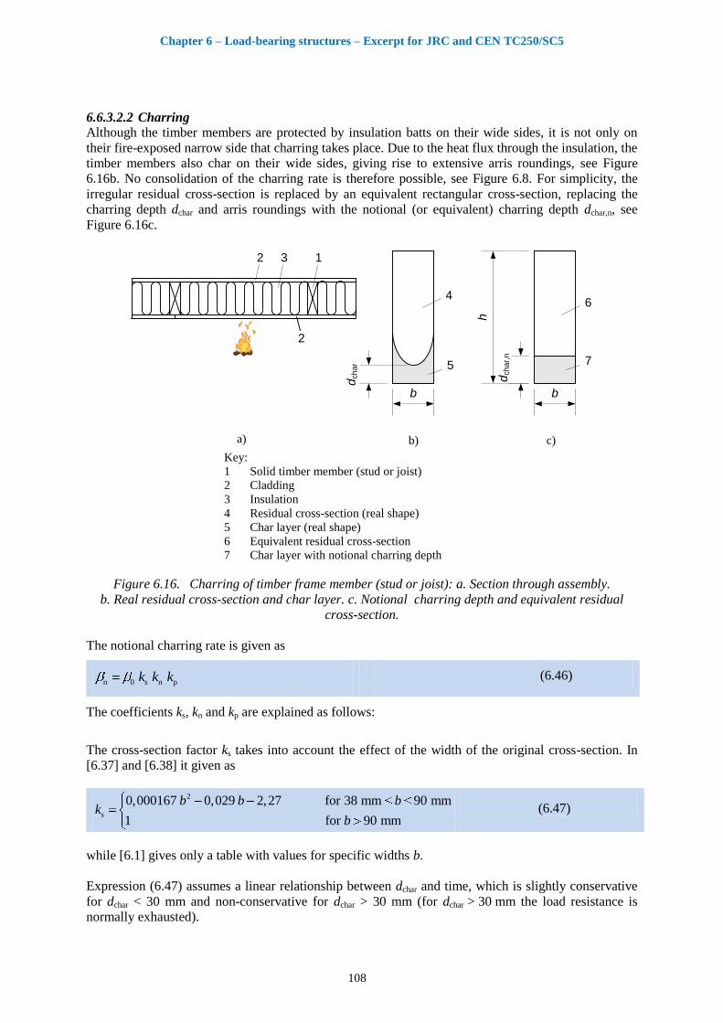
Chapter 6 – Load-bearing structures – Excerpt for JRC and CEN TC250/SC5
108
6.6.3.2.2 Charring
Although the timber members are protected by insulation batts on their wide sides, it is not only on
their fire-exposed narrow side that charring takes place. Due to the heat flux through the insulation, the
timber members also char on their wide sides, giving rise to extensive arris roundings, see Figure
6.16b. No consolidation of the charring rate is therefore possible, see Figure 6.8. For simplicity, the
irregular residual cross-section is replaced by an equivalent rectangular cross-section, replacing the
charring depth dchar and arris roundings with the notional (or equivalent) charring depth dchar,n, see
Figure 6.16c.
b
dch
ar,
n
h
6
7
b
5
4
a) c)
1
2
2 3
dch
ar
b) Key:
1 Solid timber member (stud or joist)
2 Cladding
3 Insulation
4 Residual cross-section (real shape)
5 Char layer (real shape)
6 Equivalent residual cross-section
7 Char layer with notional charring depth
Figure 6.16. Charring of timber frame member (stud or joist): a. Section through assembly.
b. Real residual cross-section and char layer. c. Notional charring depth and equivalent residual
cross-section.
The notional charring rate is given as
n 0 s n pk k k (6.46)
The coefficients ks, kn and kp are explained as follows:
The cross-section factor ks takes into account the effect of the width of the original cross-section. In
[6.37] and [6.38] it given as
2
s
0,000167 0,029 2,27 for 38 mm 90 mm
1 for 90 mm
b b bk
b (6.47)
while [6.1] gives only a table with values for specific widths b.
Expression (6.47) assumes a linear relationship between dchar and time, which is slightly conservative
for dchar < 30 mm and non-conservative for dchar > 30 mm (for dchar > 30 mm the load resistance is
normally exhausted).
Chapter 6 – Load-bearing structures – Excerpt for JRC and CEN TC250/SC5
109
New results from [6.42] show that stone wool from various producers provides somewhat less fire
protection of the wide sides of the timber member than reported in [6.38][6.39][6.40]. Expression
(6.47) should therefore be replaced with
2
s
0,00023 0,045 3,19 for 38 mm 90 mm
1 for 90 mm
b b bk
b (6.48)
This expression can be used for stone wool insulation of minimum density of 26 kg/m2.
The coefficient kn converts the irregular charring depth into a notional charring depth, see Figure 6.16b
and c. Strictly speaking, it depends on time, cross-section dimensions and the cross-section property in
question (area, section modulus or second moment of area). The value n 1,5k given by [6.1] is a
reasonable approximation for the notional charring depth that would be relevant for a relative
resistance between 0,2 and 0,4. For the more conservative conditions of lower values of relative
resistance and member widths of b > 60 mm, kn = 1,25 would be more appropriate..
The coefficient kp expresses the effect of the protection by claddings, where
p 1 1,0k k
for initially unprotected members (in practice such applications exist for attic floors
without a decking where the fire exposure is from above)
p 2k k for charring phase before the cladding has fallen off ( ch ft t )
p 3k k
for charring phase after the cladding has fallen off ( ft t ), see EN 1995-1-2 [6.1]
Annex C Expressions (C.3), (C.4) and (C.5). Expression (C.4) should only be used for timber
members over joints of Type F gypsum plasterboards with tapered edges (this is not explicitly said in
EN 1995-1-2).
The expressions for the notional charring depth, dchar,n, are given as:
char,n 0 s n 2 chd k k k t t for tch ≤ t ≤ tf (6.49)
char,n 0 s n 2 f ch 3 fd k k k t t k t t for tf ≤ t (6.50)
6.6.3.2.3 Strength and stiffness properties using the reduced properties method
According to EN 1995-1-2 [6.1] and [6.37], the strength and stiffness properties of the timber
members are determined using modification factors for fire kmod,fi, see Expressions (6.19) to (6.22).
The expressions for kmod,fi are given as:
char,n
mod,fm,fi 0 1
dk a a
h (6.51)
char,n
mod,E,fi 0 1
dk b b
h (6.52)
for strength and stiffness properties respectively, with parameters a0, a1, b0, and b1 given for specific
cross-sections in a number of tables. For other cross-sections, these parameters can be determined by
linear interpolation.
The number of cross-sections in EN 1995-1-2 [6.1] was reduced in comparison with [6.37].
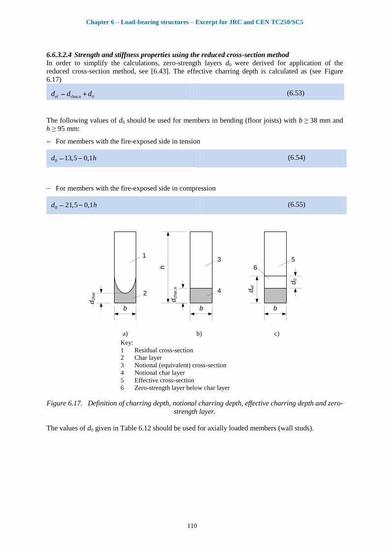
Chapter 6 – Load-bearing structures – Excerpt for JRC and CEN TC250/SC5
110
6.6.3.2.4 Strength and stiffness properties using the reduced cross-section method
In order to simplify the calculations, zero-strength layers d0 were derived for application of the
reduced cross-section method, see [6.43]. The effective charring depth is calculated as (see Figure
6.17)
ef char,n 0d d d (6.53)
The following values of d0 should be used for members in bending (floor joists) with b ≥ 38 mm and
h ≥ 95 mm:
For members with the fire-exposed side in tension
0 13,5 0,1d h (6.54)
For members with the fire-exposed side in compression
0 21,5 0,1d h (6.55)
b
dch
ar,
n
h
3
4
b
2
1
b) c)
dch
ar
b
de
f
5
d0
6
a) Key:
1 Residual cross-section
2 Char layer
3 Notional (equivalent) cross-section
4 Notional char layer
5 Effective cross-section
6 Zero-strength layer below char layer
Figure 6.17. Definition of charring depth, notional charring depth, effective charring depth and zero-
strength layer.
The values of d0 given in Table 6.12 should be used for axially loaded members (wall studs).
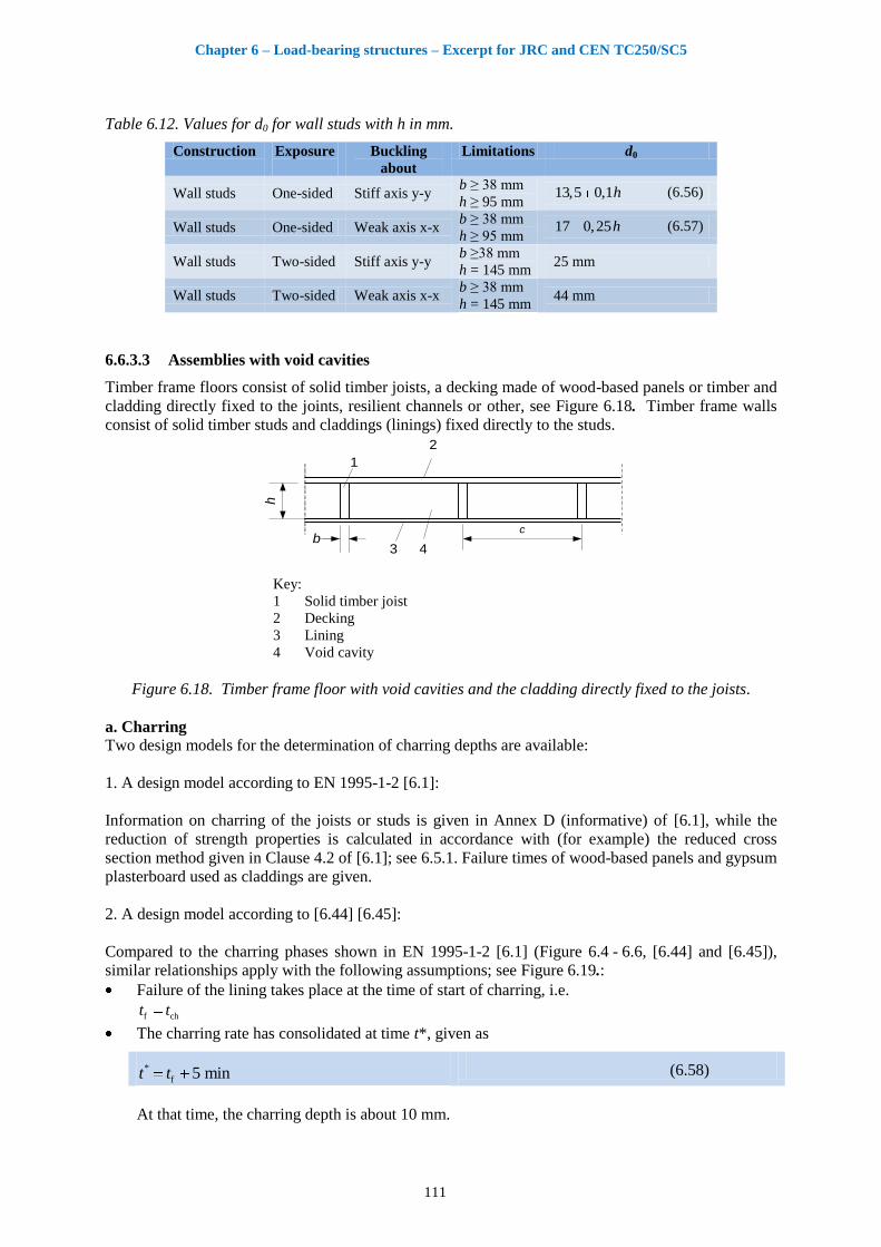
Chapter 6 – Load-bearing structures – Excerpt for JRC and CEN TC250/SC5
111
Table 6.12. Values for d0 for wall studs with h in mm.
Construction Exposure
Buckling
about
Limitations d0
Wall studs One-sided Stiff axis y-y b ≥ 38 mm
h ≥ 95 mm 13,5 0,1h (6.56)
Wall studs One-sided Weak axis x-x b ≥ 38 mm
h ≥ 95 mm 17 0,25h (6.57)
Wall studs Two-sided Stiff axis y-y b ≥38 mm
h = 145 mm 25 mm
Wall studs Two-sided Weak axis x-x b ≥ 38 mm
h = 145 mm 44 mm
6.6.3.3 Assemblies with void cavities
Timber frame floors consist of solid timber joists, a decking made of wood-based panels or timber and
cladding directly fixed to the joints, resilient channels or other, see Figure 6.18. Timber frame walls
consist of solid timber studs and claddings (linings) fixed directly to the studs.
b
h
c
2
1
3 4
Key:
1 Solid timber joist
2 Decking
3 Lining
4 Void cavity
Figure 6.18. Timber frame floor with void cavities and the cladding directly fixed to the joists.
a. Charring
Two design models for the determination of charring depths are available:
1. A design model according to EN 1995-1-2 [6.1]:
Information on charring of the joists or studs is given in Annex D (informative) of [6.1], while the
reduction of strength properties is calculated in accordance with (for example) the reduced cross
section method given in Clause 4.2 of [6.1]; see 6.5.1. Failure times of wood-based panels and gypsum
plasterboard used as claddings are given.
2. A design model according to [6.44] [6.45]:
Compared to the charring phases shown in EN 1995-1-2 [6.1] (Figure 6.4 - 6.6, [6.44] and [6.45]),
similar relationships apply with the following assumptions; see Figure 6.19.:
Failure of the lining takes place at the time of start of charring, i.e.
f cht t
The charring rate has consolidated at time t*, given as
*
f 5 mint t (6.58)
At that time, the charring depth is about 10 mm.
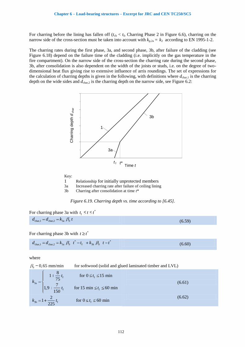
Chapter 6 – Load-bearing structures – Excerpt for JRC and CEN TC250/SC5
112
For charring before the lining has fallen off (tch < tf, Charring Phase 2 in Figure 6.6), charring on the
narrow side of the cross-section must be taken into account with kp,2a = k2 according to EN 1995-1-2.
The charring rates during the first phase, 3a, and second phase, 3b, after failure of the cladding (see
Figure 6.18) depend on the failure time of the cladding (i.e. implicitly on the gas temperature in the
fire compartment). On the narrow side of the cross-section the charring rate during the second phase,
3b, after consolidation is also dependent on the width of the joists or studs, i.e. on the degree of two-
dimensional heat flux giving rise to extensive influence of arris roundings. The set of expressions for
the calculation of charring depths is given in the following, with definitions where dchar,1 is the charring
depth on the wide sides and dchar,2 is the charring depth on the narrow side, see Figure 6.2:
Time t
Ch
arr
ing
de
pth
dch
ar
1
3a
3b
t f t*
Key:
1 Relationship for initially unprotected members 3a Increased charring rate after failure of ceiling lining
3b Charring after consolidation at time t*
Figure 6.19. Charring depth vs. time according to [6.45].
For charring phase 3a with *
ft t t
char,1 char,2 3a 0d d k t (6.59)
For charring phase 3b with *t t
* *
char,1 char,2 3a 0 f 3b 0d d k t t k t t (6.60)
where
0 0,65 mm/min for softwood (solid and glued laminated timber and LVL)
f f
3a
f f
81 for 0 15 min
75
71,9 for 15 min 60 min
150
t t
k
t t
(6.61)
3b f f
21 for 0 60 min
225k t t
(6.62)
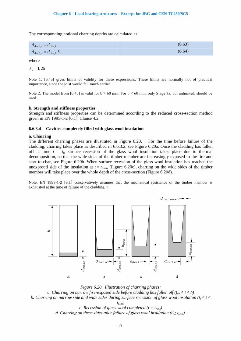
Chapter 6 – Load-bearing structures – Excerpt for JRC and CEN TC250/SC5
113
The corresponding notional charring depths are calculated as
char,1,n char,1d d (6.63)
char,2,n char,2 nd d k (6.64)
where
n 1,25k
Note 1: [6.45] gives limits of validity for these expressions. These limits are normally not of practical
importance, since the joist would fail much earlier.
Note 2: The model from [6.45] is valid for b ≥ 60 mm. For b < 60 mm, only Stage 3a, but unlimited, should be
used.
b. Strength and stiffness properties
Strength and stiffness properties can be determined according to the reduced cross-section method
given in EN 1995-1-2 [6.1], Clause 4.2.
6.6.3.4 Cavities completely filled with glass wool insulation
a. Charring
The different charring phases are illustrated in Figure 6.20. For the time before failure of the
cladding, charring takes place as described in 6.6.3.2, see Figure 6.20a. Once the cladding has fallen
off at time t = tf, surface recession of the glass wool insulation takes place due to thermal
decomposition, so that the wide sides of the timber member are increasingly exposed to the fire and
start to char, see Figure 6.20b. When surface recession of the glass wool insulation has reached the
unexposed side of the insulation at t = tf,ins, (Figure 6.20c), charring on the wide sides of the timber
member will take place over the whole depth of the cross-section (Figure 6.20d).
Note: EN 1995-1-2 [6.1] conservatively assumes that the mechanical resistance of the timber member is
exhausted at the time of failure of the cladding, tf.
dchar,
2,n
dchar,
2,n
dchar,
2,n
dch
ar,
2,nh
char,
2b
dchar,1,n dchar,1,n dchar,1,n
dchar,1,n,unexp
a dcb
h
Figure 6.20. Illustration of charring phases:
a. Charring on narrow fire-exposed side before cladding has fallen off (tch ≤ t ≤ tf)
b. Charring on narrow side and wide sides during surface recession of glass wool insulation (tf ≤ t ≤
tf,ins)
c. Recession of glass wool completed (t = tf,ins)
d. Charring on three sides after failure of glass wool insulation (t ≥ tf,ins).

Chapter 6 – Load-bearing structures – Excerpt for JRC and CEN TC250/SC5
114
In the following, it is assumed either that the cladding remains in place after the start of charring of the
timber member, i.e. , tch ≤ tf, or that the cladding falls off at the time of start of charring, i.e. tch = tf.
For tch ≤ t ≤ tf (Figure 6.20a) the design model described in 6.6.3.2 applies:
char,n 0 s n 2 f chd k k k t t (6.65)
For tf ≤ t ≤ tf,ins (Figure 6.20b) where tf,ins is the time after complete recession of the insulation given by
f,ins frec,ins
ht t
v
(6.66)
the notional charring depths should be calculated as:
char,1,n 3 0 fd k t t (6.67)
char,3 rec,ins f( )h v t t (6.68)
char,2,n 0 2 s n f ch 3 n f( ) ( )d k k k t t k t t (6.69)
where
vrec,ins is the surface recession rate for glass wool insulation [6.35]:
rec,ins 30 mm/minv
k2 is the insulation factor of the cladding from EN 1995-1-2 [6.1] expressions (C.3) or (C.4), given
as:
2 p1,05 0,0073k h for unjointed claddings (6.70)
2 p0,86 0,0073k h for jointed claddings (6.71)
k3 is the post-protection factor, given as, see Expression (6.61),
f f
3a
f f
81 for 0 15 min
75
71,9 for 15 min 60 min
150
t t
k
t t
(6.72)
3b f f
21 for 0 60 min
225k t t (6.73)
Note: Since this stage is relatively short, intermediate values of cross-section properties can also be
determined by linear interpolation of cross-section properties calculated at time ft t and f,ins .t t
For t ≥ tf,ins (Figure 6.20d) the notional charring depth dchar,1,n should be calculated according to
Expression (6.67) and the charring depths at the unexposed edge of the wide sides of the timber
member should be calculated as:
char,1,unexp,n 3 0 f,ins( )d k t t (6.74)
b. Strength and stiffness properties
For tch ≤ t ≤ tf, the design model described in 6.6.3.2 applies.
For t > tf, the reduced cross-section method given by EN 1995-1-2 [6.1], Clause 4.2.2 should be used,
i.e. the charring depth should be increased by d0 = 7 mm. Note: For assemblies with tch ≤ tf, at time t = tf and shortly after, this is not consistent with 6.6.3.2.
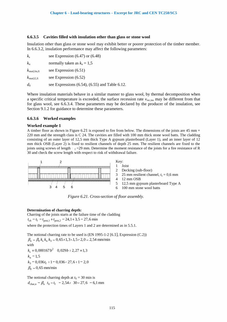
Chapter 6 – Load-bearing structures – Excerpt for JRC and CEN TC250/SC5
115
6.6.3.5 Cavities filled with insulation other than glass or stone wool
Insulation other than glass or stone wool may exhibit better or poorer protection of the timber member.
In 6.6.3.2, insulation performance may affect the following parameters:
ks see Expression (6.47) or (6.48)
kn normally taken as kn = 1,5
kmod,fm,fi see Expression (6.51)
kmod,E,fi see Expression (6.52)
d0 see Expressions (6.54), (6.55) and Table 6.12.
Where insulation materials behave in a similar manner to glass wool, by thermal decomposition when
a specific critical temperature is exceeded, the surface recession rate vrec,ins may be different from that
for glass wool, see 6.6.3.4. These parameters may be declared by the producer of the insulation, see
Section 9.1.2 for guidance to determine these parameters.
6.6.3.6 Worked examples
Worked example 1 A timber floor as shown in Figure 6.21 is exposed to fire from below. The dimensions of the joists are 45 mm ×
220 mm and the strength class is C 24. The cavities are filled with 100 mm thick stone wool batts. The cladding
consisting of an outer layer of 12,5 mm thick Type A gypsum plasterboard (Layer 1), and an inner layer of 12
mm thick OSB (Layer 2) is fixed to resilient channels of depth 25 mm. The resilient channels are fixed to the
joists using screws of length f =29 mm. Determine the moment resistance of the joists for a fire resistance of R
30 and check the screw length with respect to risk of withdrawal failure.
21
3 4 5 6
Key:
1 Joist
2 Decking (sub-floor)
3 25 mm resilient channel, ts = 0,6 mm
4 12 mm OSB
5 12,5 mm gypsum plasterboard Type A
6 100 mm stone wool batts
Figure 6.21. Cross-section of floor assembly.
Determination of charring depth:
Charring of the joists starts at the failure time of the cladding
ch f prot,1 prot,2 24,1 3,5 27,6 mint t t t
where the protection times of Layers 1 and 2 are determined as in 5.5.1.
The notional charring rate to be used is (EN 1995-1-2 [6.1], Expression (C.2))
n 0 s n 3 0,65 1,3 1,5 2,0 2,54 mm/mink k k
with 2
s 0,000167 0,029 2,27 1,3k b b
n 1,5k
3 f0,036 1 0,036 27,6 1 2,0k t
0 0,65 mm/min
The notional charring depth at tfi = 30 min is
char,n n fi f 2,54 30 27,6 6,1 mmd t t
Chapter 6 – Load-bearing structures – Excerpt for JRC and CEN TC250/SC5
116
Determination of design moment resistance in fire in accordance with EN 1995-1-2 [6.1], Annex C:
The section modulus of the notional residual cross-section is 2 2
char,n 3r
45 220 6,1343149 mm
6 6
b h dW
The design bending strength in fire is
m,km,d,fi mod,fi fi
M,fi
ff k k , see Expression (6.19)
With a0 = 0,76 and a1 = 0,51 (see EN 1995-1-2 [6.1], table C2)
char,nmod,fm,fi 0 1
6,10,76 0,51 0,746
220
dk a a
h (see Expression (6.51))
2m,k 24 N/mmf
fi 1,25k (see EN 1995-1-2 [6.1], Clause 2.3)
M,fi 1,0
2m,d,fi
240,746 1,25 22,4 N/mm
1,0f
the design moment resistance in fire is
d,fi r m,d,fi 343.149 22,4 7.679.675 Nmm = 7,68 kNmM W f
Determination of design moment resistance in fire by the reduced cross section method, see 6.6.3.2.4:
Calculate the effective charring depth using Expressions (6.53) and (6.54)
0 13,5 0,1 13,5 0,1 220 35,5 mmd h
ef char,n 0 6,1 35,5 41,6 mmd d d
The section modulus of the effective residual cross-section is 2 2
ef 3ef
45 220 41,6238.699 mm
6 6
b h dW
The design moment resistance in fire is
fid,fi ef m,k
M,fi
1,25238.699 24 7.160.976 Nmm = 7,16 kNm
1,0
kM W f
Check of screw length:
Calculate the failure time of the screws, tsf, in accordance with EN 1995-1-2 [6.1], Expression (C.12) as
f a,min s 2 n 0 f ch ssf f req
s 3 n 0
( ) 29 10 0 0,627,6 34,9 min > = 30 min
1,3 2,0 1,5 0,65
k k k t t tt t t
k k k
Conclusion: There is no risk of premature failure of the resilient channels.
Worked example 2 A wall assembly with a total height of 2800 mm, including top and sole plates, is shown in Figure 6.22. The
dimensions of the studs are 45 mm × 145 mm. The strength class of the studs is C 24. The cavities are
completely filled with 145 mm batt-type stone wool. The cladding on the fire-exposed side consists of one layer
of 15 mm thick Type F gypsum plasterboard with a declared failure time from the producer. The cladding on the
unexposed side is made of one layer of Type H gypsum plasterboard. The length of the screws on the fire-
exposed side is f = 52 mm. Determine the design value of the axial load resistance of a stud without a cladding
joint above it for a fire resistance of R 60.
31
2 4
Key:
1 Stud
2 Cladding on fire-exposed side:
15 mm gypsum plasterboard Type F
3 Cladding on unexposed side:
9 mm gypsum plasterboard Type H
4 145 mm stone wool batts
Figure 6.22. Cross-section of wall assembly.

Chapter 6 – Load-bearing structures – Excerpt for JRC and CEN TC250/SC5
117
Determination of charring depth:
The time of start of charring is given by EN 1995-1-2 [6.1] Expression (3.11), as
ch p2,8 14 2,8 15 14 28 mint h
The insulation factor, k2, is given by EN 1995-1-2 [6.1], Expression (C.3), as
2 p1,05 0,0073 1,05 0,0073 15 0,94k h
The failure time of the cladding with respect to thermal degradation is declared by the producer as
f 65 min.t
The failure time of the cladding with respect to pull-out failure of screws is (see EN 1995-1-2 [6.1], Expression
(C.9)), calculated as
f a,min p
f chs 2 n j 0
52 10 1528 50,7 min 65 min
1,3 0,94 1,5 1,0 0,65
ht t
k k k k
The post-protection factor, k3, is given by EN 1995-1-2 [6.1], Expression (C.5), as
3 f0,036 1 0,036 50,7 1 2,825k t
The notional charring depth at 60 minutes is:
char,n s 2 0 f ch s 3 0
1,3 0,94 0,65 50,7 28 1,3 2,825 0,65 60 50,7 40,2 mm
d k k t t k k
The dimensions of the residual cross-section of the studs are
r 45 mmb
r 145 40,2 104,8 mmh
Determination of design value of axial resistance in fire in accordance with EN 1995-1-2 [6.1], Annex C:
With
0 0,55a
1 0,40a
0 0,60b
1 0,84b
Calculate the modification factors for fire (for compressive strength and modulus of elasticity respectively): see
EN 1995-1-2 [6.1], Expressions (C.13) and (C.14):
char,nmod,fc,fi 0 1
40,20,55 0,40 0,44
145
dk a a
h
char,nmod,E,fi 0 1
40,20,60 0,84 0,36
145
dk b b
h
The design values of compressive strength and modulus of elasticity are, see Expressions (6.19) and (6.22):
c,k 2
c,d,fi mod,fc,fi fi
M,fi
210,44 1,25 11,55 N/mm
1,0
ff k k
205
d,fi mod,E,fi fi
M,fi
74000,36 1,25 3300 N/mm
1,0
EE k k
With EN 1995-1-1 [6.16], Expressions (6.21) to (6.29), we get
y y
yr
12 2800 1292,55
104,8i h
y mod,fc,fi c,0,krel,y
mod,E,fi 0,05
92,55 0,44 211,73
π π 0,36 7400
k f
k E
c 0,2
2 2y c rel,y rel,y0,5 1 0,3 0,5 1 0,2 1,73 0,3 1,73 2,139k
c,y2 2 2 2
y y rel,y
1 10,294
2,139 2,139 1,73k
k k
The design value of the axial load resistance of one stud is
d,f i r c,y c,d,fi 45 104,8 0,294 11,55 16.014 N 16,0 kNN A k f
Chapter 6 – Load-bearing structures – Excerpt for JRC and CEN TC250/SC5
118
Determination of design value of axial resistance in fire by the reduced cross-section method, see 6.6.3.2.4:
Calculate the effective charring depth as (Expressions (6.53) and (6.56)):
0 13,5 0,1 13,5 0,1 145 28,0 mmd h
ef char,n 0 40,2 28,0 68,2 mmd d d
The effective depth of the cross-section is
r,ef 145 68,2 76,8 mmh
With mod,fc,fi 1,0k , the design value of compressive strength in fire is calculated as
c,k 2
c,d,fi mod,fc,fi fi
M,fi
211,0 1,25 26,25 N/mm
1,0
ff k k
With EN 1995-1-1 [6.16], Expressions (6.21) to (6.29), we get
y y
yr,ef
12 2800 12126,3
76,8i h
y mod,fc,fi c,0,krel,y
mod,E,fi 0,05
126,3 1,0 212,14
π π 1,0 7400
k f
k E
c 0,2
2 2y c rel,y rel,y0,5 1 0,3 0,5 1 0,2 2,14 0,3 2,14 2,977k
c,y2 2 2 2
y y rel,y
1 10,198
2,977 2,977 2,14k
k k
The design value of the axial load resistance of one stud is
d,f i r c,y c,d,fi 45 76,8 0,198 26,25 17.963 N 18,0 kNN A k f
6.6.4 Light weight timber frame floors with I-joists
6.6.4.1 General
The following design model is taken from [6.46]. For general aspects, see 6.6.3.1. For partially filled
cavities, see 6.6.3.2.1.
6.6.4.2 Cross-section
The dimensions of an I-joist are shown in Figure 6.23. At ambient temperature, the characteristic
moment resistance is calculated as:
k m,k ef hM f W k (6.75)
With
efef
2IW
h (6.76)
wef f w
f
EI I I
E (6.77)
where:
fm,k is the characteristic bending strength of the I-joist, see below;
Ef is the mean value of the modulus of elasticity of the flange;
Ew is the mean value of the modulus of elasticity of the web;
If is the contribution of the flanges to the second moment of area;
Iw is the contribution of the web to the second moment of area;
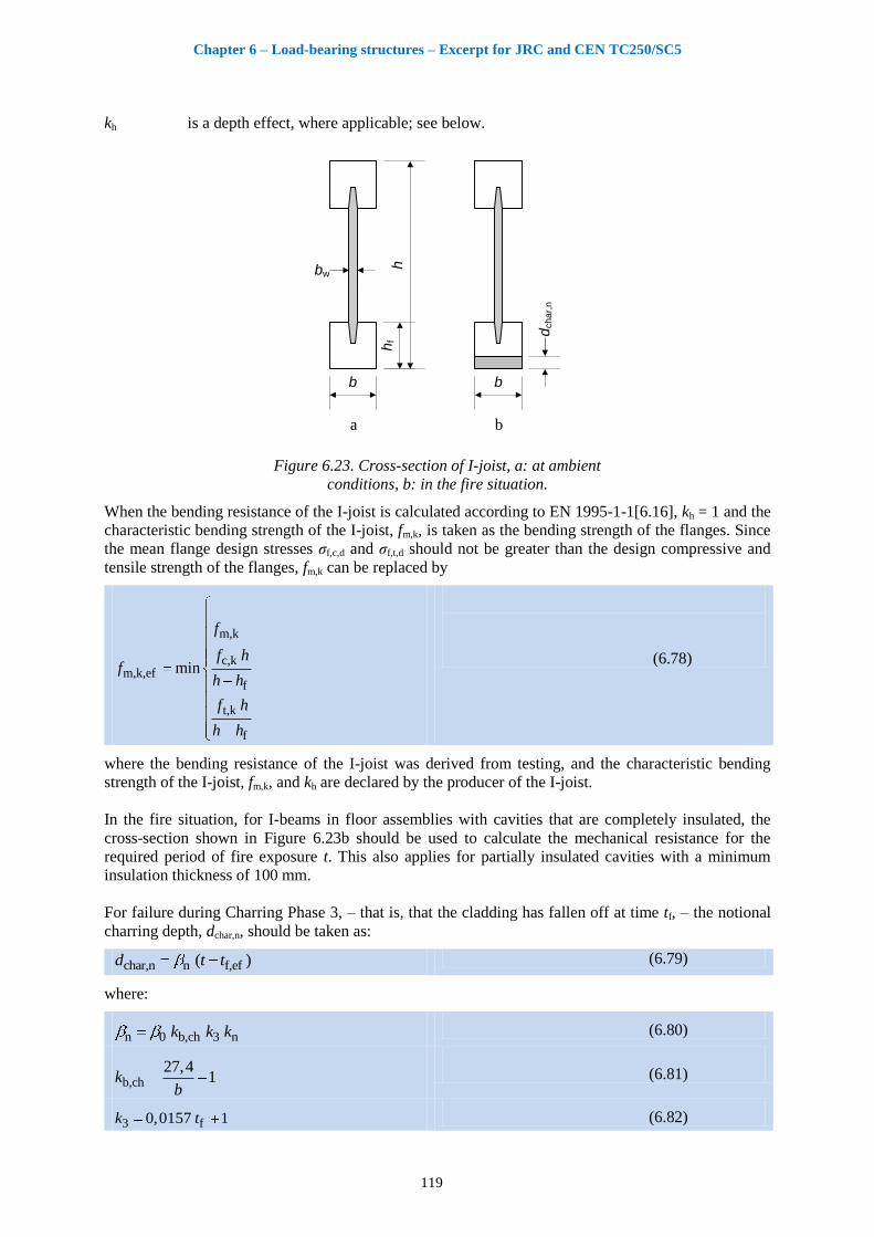
Chapter 6 – Load-bearing structures – Excerpt for JRC and CEN TC250/SC5
119
kh is a depth effect, where applicable; see below.
hb
bw
hf
a
b
dch
ar,
n
b
Figure 6.23. Cross-section of I-joist, a: at ambient
conditions, b: in the fire situation.
When the bending resistance of the I-joist is calculated according to EN 1995-1-1[6.16], kh = 1 and the
characteristic bending strength of the I-joist, fm,k, is taken as the bending strength of the flanges. Since
the mean flange design stresses σf,c,d and σf,t,d should not be greater than the design compressive and
tensile strength of the flanges, fm,k can be replaced by
m,k
c,km,k,ef
f
t,k
f
min
f
f hf
h h
f h
h h
(6.78)
where the bending resistance of the I-joist was derived from testing, and the characteristic bending
strength of the I-joist, fm,k, and kh are declared by the producer of the I-joist.
In the fire situation, for I-beams in floor assemblies with cavities that are completely insulated, the
cross-section shown in Figure 6.23b should be used to calculate the mechanical resistance for the
required period of fire exposure t. This also applies for partially insulated cavities with a minimum
insulation thickness of 100 mm.
For failure during Charring Phase 3, – that is, that the cladding has fallen off at time tf, – the notional
charring depth, dchar,n, should be taken as:
char,n n f,ef( )d t t (6.79)
where:
n 0 b,ch 3 nk k k (6.80)
b,ch27,4
1kb
(6.81)
3 f0,0157 1k t (6.82)

Chapter 6 – Load-bearing structures – Excerpt for JRC and CEN TC250/SC5
120
f,ef f0,9t t (6.83)
n 1,4k
β0 is the one-dimensional charring rate given in EN 1995-1-2 [6.1], i.e. β0 = 0,65 mm/min for solid
softwood and LVL;
tf is the failure time of the cladding, in mm. It may be given by EN 1995-1-2 [6.1] or by the
producer, or be determined with respect to withdrawal failure of cladding fasteners.
tf,ef is the effective failure time of the cladding;
b is the flange width in mm.
For failure during Charring Phase 2, i.e. that failure takes place at or before the time of failure of the
cladding, the notional charring depth, dchar,n, should be taken as:
char,n n ch( )d t t (6.84)
where:
n 0 b,ch 2 nk k k (6.85)
and 2 1k .
6.6.4.3 Failure of cladding fasteners
The penetration length of fasteners for fixing claddings or resilient channels should be at least 10 mm
into unburnt wood. The charring depth may be taken as the notional charring depth dchar,n.
6.6.4.4 Strength parameters
For I-joists in bending where the fire-exposed flange is in tension, the modification factor for bending
strength, kmod,fm,fi, should be calculated as:
mod,fm,fi char,n b,fm hf,fm h,fm1 0,016k d k k k (6.86)
With
b,fm11,5
0,76kb
(6.87)
hf,fmf
680,41k
h (6.88)
h,fm80
1,4kh
(6.89)
where the notional charring depth dchar,n, the flange width b, the flange depth hf and cross-section depth
h are in mm.
For the influence of finger joints, see Sub-clause 6.5.4.1.5 below.
For shear strength verification of the web, the maximum temperature of the web should be calculated
as:
b char,nw,max
f
16047
k d
h (6.90)
Chapter 6 – Load-bearing structures – Excerpt for JRC and CEN TC250/SC5
121
For wood-based webs, the modification factor for shear strength, kmod,fv,fi, may be calculated, using the
reduction factor for shear strength given in Figure B4 of EN 1995-1-2 [6.1], as:
b,ch char,n
fmod,fv,fi
b,ch char,n b,ch char,n
f f
481 for 20
1,13 481,47 for 20
k d
hk
k d k d
h h
(6.91)
For shear strength verification of the glue-line between the web and the flange, the temperature in
degrees Celsius should be taken as:
b,chchar,n
joint f
666 12 max
20
kd
b h (6.92)
where dchar,n, b and hf are in mm.
6.6.4.5 Finger-joint strength in flanges
Finger joint strength in fire may be dependent on the adhesive being used [6.10]. Since I-joists are
sensitive to finger joint failure, the bending resistance should be determined for the design bending
strength given as, replacing Expression (6.19):
km,d,fi mod,fi mod,fj,fi fi
M,fi
ff k k k (6.93)
where kmod,fj,fi is the modification factor for fire, expressing the reduction of finger joint strength given
in Table 6.13.
Table 6.13. Modification factors for fire for finger joints.
Adhesive kmod,fj,fi
PRF (phenolic resorcinol
formaldehyde)
1,0
MUF (melamine urea formaldehyde) 0,75
PUR (polyurethane) 0,75
6.6.4.6 Reduced cross-section method for bending strength
For application of the reduced cross-section method, see 6.5.1 or 6.6.3.2, the depth of the zero-strength
layer should be calculated as, see Figure 6.24:
0 f f5,3 0,165 0,018 0,0006d h b h b (6.94)

Chapter 6 – Load-bearing structures – Excerpt for JRC and CEN TC250/SC5
122
b
dch
ar,
na
b
de
f
d0
b
Figure 6.24. Definition of notional
charring depth dchar,n, zero-strength
layer d0 and effective charring depth def.
6.6.5 Other structural elements
6.6.5.1 Timber decks made of hollow core elements
6.6.5.1.1 General
The following design model is taken from [6.47]. It was developed based on fire tests of timber decks
made of hollow core elements with either void or insulation filled cavities. Stone wool typically used
in Switzerland was used for the fire tests performed with filled cavities. In the design model, strength
properties are determined using the reduced cross-section method.
6.6.5.1.2 Charring
The charring model takes into account two different charring phases as shown in Figure 6.25. The first
charring phase is given by the time needed for complete burn-through of the fire-exposed bottom
timber layer, i.e. dchar,n ≤ hu). The second charring phase is characterised by charring of the vertical
timber members (the webs) after the charring depth has reached the thickness of the fire-exposed
bottom timber layer (dchar,n ≥ hu). For simplicity, linear relationships between charring depth and time
are assumed for each phase. Further, it is assumed that the vertical timber members are not exposed to
fire on three sides during the required fire resistance. Thus the fire-exposed bottom timber layer is
designed such that a fire penetration into the cavities is prevented, or the cavities are filled with
mineral wool batts with a degradation point greater than 1000°C, remaining in place after the charred
fire-exposed bottom timber layer has fallen off.

Chapter 6 – Load-bearing structures – Excerpt for JRC and CEN TC250/SC5
123
Figure 6.25. Charring model for the calculation of the residual cross-section of the
hollow core elements.
The time t1, when the charring depth has reached the thickness of the fire-exposed timber layer
(dchar,n = hu) should be calculated using the notional charring rate 1,n for the first charring phase as
following:
u1
1,n
ht (6.95)
For a required time of fire resistance, treq, the notional charring depth for the vertical members of the
hollow core elements should be calculated as:
char,n 1,n reqd t for 0 ≤ treq ≤ t1 (6.96)
char,n u 2,n req 1d h t t for treq ≥ t1 (6.97)
Since timber decks made of hollow core elements are load-bearing, charring rates should be taken
from EN 1995-1-2 [6.1] Table 3.1 in rows a to c, but not d (wood-panelling). For the first charring
phase, due to joints between the hollow core elements, the influence of increased charring should be
taken into account by using notional charring rates given in table 3.1 in [6.1] rather than the one-
dimensional values, i.e. 1,n = 0,8 mm/min for hollow core elements made of solid timber. The
notional charring rate 2,n for the second charring phase is mainly influenced by the thickness of the
vertical members and should be calculated as
2,n 0 s nk k (6.98)
where the coefficient ks should be taken from Expression (6.32) and kn = 1.5. Expression (6.32) takes
into account the protective function of the wide sides of the vertical member using stone wool from
various producers.
6.6.5.1.3 Strength and stiffness properties
The reduced cross-section method should be used for the design of timber decks made of hollow core
elements, see 6.4. Calculate the effective charring depth in accordance with Expression (6.99), using
the values of d0 as given in Table 6.14.
Table 6.14. Values of d0.
Charring phase d0
mm
First charring phase dchar,n hu 7
Second charring phase dchar,n > hu 20
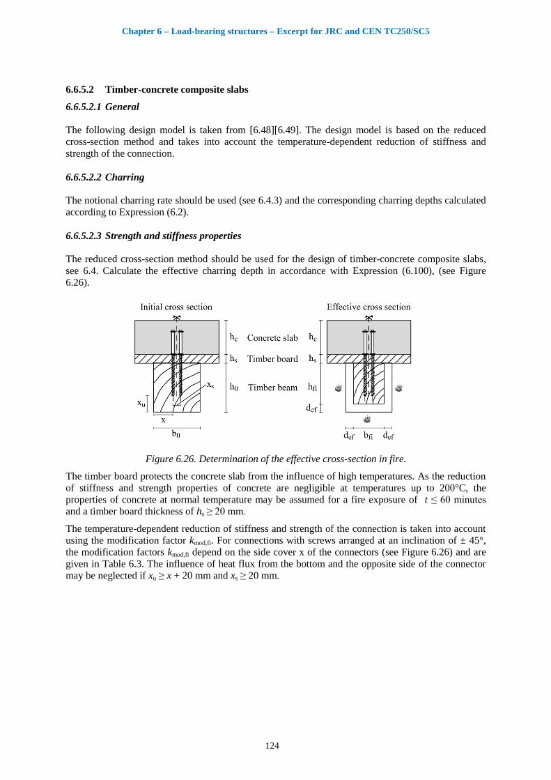
Chapter 6 – Load-bearing structures – Excerpt for JRC and CEN TC250/SC5
124
6.6.5.2 Timber-concrete composite slabs
6.6.5.2.1 General
The following design model is taken from [6.48][6.49]. The design model is based on the reduced
cross-section method and takes into account the temperature-dependent reduction of stiffness and
strength of the connection.
6.6.5.2.2 Charring
The notional charring rate should be used (see 6.4.3) and the corresponding charring depths calculated
according to Expression (6.2).
6.6.5.2.3 Strength and stiffness properties
The reduced cross-section method should be used for the design of timber-concrete composite slabs,
see 6.4. Calculate the effective charring depth in accordance with Expression (6.100), (see Figure
6.26).
Figure 6.26. Determination of the effective cross-section in fire.
The timber board protects the concrete slab from the influence of high temperatures. As the reduction
of stiffness and strength properties of concrete are negligible at temperatures up to 200°C, the
properties of concrete at normal temperature may be assumed for a fire exposure of t ≤ 60 minutes
and a timber board thickness of hs ≥ 20 mm.
The temperature-dependent reduction of stiffness and strength of the connection is taken into account
using the modification factor kmod,fi. For connections with screws arranged at an inclination of ± 45°,
the modification factors kmod,fi depend on the side cover x of the connectors (see Figure 6.26) and are
given in Table 6.3. The influence of heat flux from the bottom and the opposite side of the connector
may be neglected if xu ≥ x + 20 mm and xs ≥ 20 mm.
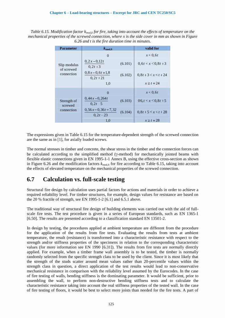
Chapter 6 – Load-bearing structures – Excerpt for JRC and CEN TC250/SC5
125
Table 6.15. Modification factor kmod,fi for fire, taking into account the effects of temperature on the
mechanical properties of the screwed connection, where x is the side cover in mm as shown in Figure
6.26 and t is the fire duration time in minutes.
Parameter kmod,fi valid for
Slip modulus
of screwed
connection
0 0,6x t
0,2 0,12
0,2 3
x t
t (6.101) 0,6 0,8 3t x t
0,8 0,6 1,8
0,2 21
x t
t (6.102) 0,8 3 24t x t
1,0 24tx
Strength of
screwed
connection
0 0,6x t
0,44 0,264
0,2 5
x t
t (6.103) 06, 0,8 5t x t
0,56 0,36 7,32
0,2 23
x t
t (6.104) 0,8 5 28t x t
1,0 28tx
The expressions given in Table 6.15 for the temperature-dependent strength of the screwed connection
are the same as in [1], for axially loaded screws.
The normal stresses in timber and concrete, the shear stress in the timber and the connection forces can
be calculated according to the simplified method ( -method) for mechanically jointed beams with
flexible elastic connections given in EN 1995-1-1 Annex B, using the effective cross-section as shown
in Figure 6.26 and the modification factors kmod,fi for fire according to Table 6.15, taking into account
the effects of elevated temperature on the mechanical properties of the screwed connection.
6.7 Calculation vs. full-scale testing
Structural fire design by calculation uses partial factors for actions and materials in order to achieve a
required reliability level. For timber structures, for example, design values for resistance are based on
the 20 % fractile of strength, see EN 1995-1-2 [6.1] and 6.5.1 above.
The traditional way of structural fire design of building elements was carried out with the aid of full-
scale fire tests. The test procedure is given in a series of European standards, such as EN 1365-1
[6.50]. The results are presented according to a classification standard EN 13501-2.
In design by testing, the procedures applied at ambient temperature are different from the procedure
for the application of the results from fire tests. Evaluating the results from tests at ambient
temperature, the result (resistance) is transformed into a characteristic resistance with respect to the
strength and/or stiffness properties of the specimens in relation to the corresponding characteristic
values (for more information see EN 1990 [6.31]). The results from fire tests are normally directly
applied. For example, when a timber frame wall assembly is to be tested, the timber is normally
randomly selected from the specific strength class to be used by the client. Since it is most likely that
the strength of the studs scatter around mean values rather than 20-percentile values within the
strength class in question, a direct application of the test results would lead to non-conservative
mechanical resistance in comparison with the reliability level assumed by the Eurocodes. In the case
of fire testing of walls, bending stiffness is the dominating parameter. It would be sufficient, prior to
assembling the wall, to perform non-destructive bending stiffness tests and to calculate the
characteristic resistance taking into account the real stiffness properties of the tested wall. In the case
of fire testing of floors, it would be best to select more joists than needed for the fire tests. A part of
Chapter 6 – Load-bearing structures – Excerpt for JRC and CEN TC250/SC5
126
the material should be tested in bending (destructive bending tests) in order to determine (ambient)
bending strength.
In order to eliminate inconsistency between the reliability system of Structural Eurocodes and
application of results from full-scale fire testing, the procedure of selecting materials should be
improved and include methods for determining strength and stiffness properties of the test specimens
to be tested.
6.8 References
[6.1] EN 1995-1-2:2004, Eurocode 5. Design of timber structures – Part 1-2: General – Structural fire
design. European Standard. European Committee for Standardization, Brussels, 2004.
[6.2] EN 1995-1-2:2004/AC:2006, Eurocode 5. Design of timber structures – Part 1-2: General – Structural
fire design. Corrigendum. European Standard. European Committee for Standardization, Brussels,
2006.
[6.3] EN 1995-1-2:2004/AC:2008, Eurocode 5. Design of timber structures – Part 1-2: General – Structural
fire design. Corrigendum. European Standard. European Committee for Standardization, Brussels,
2008.
[6.4] EN 520:2004. Gypsum plasterboards – Definitions, requirements and test methods. European
Committee for Standardization, Brussels, 2004.
[6.5] EN 15283-2:2008. Gypsum boards with fibrous reinforcement – Definitions, requirements and test
methods - Part 2: Gypsum fibre boards, European Standard, CEN, Brussels, 2008.
[6.6] Just A, Schmid J, König J. Gypsum plasterboards used as fire protection – Analysis of a database.
SP Report 2010:29, Stockholm, 2010.
[6.7] EN 13162:2008. Thermal insulation products for buildings - Factory made mineral wool (MW)
products – Specification. European Committee for Standardization, Brussels, 2008.
[6.8] EN 301:1997. Adhesives, phenolic and aminoplastic for load-bearing timber structures – Classification
and specifications. European Committee for Standardization, Brussels, 1997.
[6.9] EN 15425:2008. Adhesives - One component polyurethane for load bearing timber structures -
Classification and performance requirements. European Committee for Standardization, Brussels,
2008.
[6.10] König J, Norén J, Sterley M. Effect of adhesives on finger joint performance in fire. CIB W18, Meeting
41, St. Andrews, Canada. Lehrstuhl für Ingenieurholzbau, University of Karlsruhe, Karlsruhe,
Germany, 2008.
[6.11] Schaffer E L. Charring rate of selected woods – transverse to grain. U.S. Department of Agriculture,
Forest Service, Forest Products Laboratory, Research paper FPL 69, Madison, 1967.
[6.12] Frangi A, König J. Effect of increased charring on the narrow side of rectangular timber cross-sections
exposed to fire on three or four sides. Accepted for publication in Fire and Materials, 2010.
[6.13] Fornather J, Bergmeister K, Hochreiner G. Versuchsbericht – Kleinbrandversuchsreihe 2 Teil 1 (KBV
2/1) – Versuche mit Rissen. Universität für Bodenkultur, Institut für konstruktiven Ingenieurbau.
Vienna, 2001.
[6.14] EN 12369-1:2001. Wood-based panels – Characteristic values for structural design – Part 1: OSB,
particleboards and fibreboards. European Standard. European Committee for Standardization, Brussels,
2001.
[6.15] Frangi A, Fontana M, Hugi E, Jöbstl R. Experimental analysis of cross-laminated timber panels in fire.
Fire Safety Journal, 2009.
[6.16] EN 1995-1-1:2004 Eurocode 5. Design of timber structures – Part 1-1 – General – Common rules and
rules for buildings. European Standard. European Committee for Standardization, Brussels, 2004.
[6.17] König, J. Structural fire design according to Eurocode 5—design rules and their background. Fire and
Materials. 29:147-163, 2005.
Chapter 6 – Load-bearing structures – Excerpt for JRC and CEN TC250/SC5
127
[6.18] EN 338:2008. Structural timber – Strength classes. European Standard, CEN, European Committee for
Standardization, Brussels, 2008.
[6.19] König J. Effective thermal actions and thermal properties of timber members in natural fires. Fire and
Materials. 30:51-63, 2006.
[6.20] Källsner B, König J, 2000. Thermal and mechanical properties of timber and some other materials used
in light timber frame construction. CIB W18, Meeting 33, Delft. Lehrstuhl für Ingenieurholzbau,
University of Karlsruhe, Karlsruhe, Germany, 2000.
[6.21] Franssen J M. User’s manual for SAFIR 2007. A computer program for analysis of structures.
University of Liege, Department ArGEnCo, Service Structural Engineering, 2007.
[6.22] ANSYS Handbuch. FEM für Praktiker – Band 3: Temperaturfelder. 4. Auflage, Expert Verlag,
Renningen, Deutschland, 2001.
[6.23] Schleifer V. Zum Verhalten von raumabschliessenden mehrschichtigen Holzbauteilen im Brandfall.
PhD Thesis No. 18156, ETH Zürich, 2009.
[6.24] Reden G, Fornather J, Bergmeister K, Luggin W, Hartl H, Stöffler C, Giertlová Z. Anhang A - D,
Mittelbrandversuchsserie - MBV 1, Brandversuche unter Zug- und Druckbelastung. Universität für
Bodenkultur, Institut für konstruktiven Ingenieurbau. Vienna, 2002
[6.25] König J, Källsner B. Cross-section properties of fire exposed rectangular timber members. CIB W18,
Meeting 34, Venice. Lehrstuhl für Ingenieurholzbau, University of Karlsruhe, Karlsruhe, Germany,
2001.
[6.26] Thunell B. Hållfasthetsegenskaper hos svenskt furuvirke utan kvistar och defekter. Royal Swedish
Institute for Engineering Research, Proceedings No. 161, Stockholm, 1941.
[6.27] EN 1194:1999. Glued laminated timber – Strength classes and determination of characteristic values.
CEN, European Committee for Standardization, Brussels, 2008.
[6.28] König J, Schmid J. Bonded timber deck plates in fire. CIB W18, Meeting 40, Bled, Slovakia. Lehrstuhl
für Ingenieurholzbau, University of Karlsruhe, Karlsruhe, Germany, 2007.
[6.29] EN 1991-1-1:2002, Eurode 1. Actions on structures – Part 1-1: General actions – Densities, self-
weight, imposed loads for buildings. CEN, European Committee for Standardization, Brussels, 2002.
[6.30] EN 1995-2:2004, Eurocode 5. Design of timber structures – Part 2: Bridges. European Standard.
European Committee for Standardization, Brussels, 2004.
[6.31] EN 1990:2002 Eurocode. Basis of structural design. CEN, European Committee for Standardization,
Brussels, 2002.
[6.32] König J. Basic and notional charring rates. CIB W18, Meeting 35, Kyoto. Lehrstuhl für Ingenieur-
holzbau, University of Karlsruhe, Karlsruhe, Germany, 2002.
[6.33] Schmid J, König J. Cross-laminated timber in fire. SP Report 2010:11, Stockholm, 2010.
[6.34] Schmid J, König J, Köhler J. Fire-exposed cross-laminated timber – Modelling and tests. World Conf.
on Timber Engineering 2010, Riva del Garda, Trentino, Italy, 2010.
[6.35] Just A. Post protection behaviour of wooden wall and floor construction completely filled with glass
wool. SP Report 2010:28, Stockholm, 2010.
[6.36] König J. The structural behaviour of axially loaded wood studs exposed to fire on one side. Trätek,
Swedish Institute for Wood Technology Research, Report I 8808057, Stockholm, 1988.
[6.37] Östman B, König J, Mikkola E, Stenstad V, Carlsson J, Karlsson B. Brandsäkra trähus. Version 2.
Trätek, Swedish Institute for Wood Technology Research, Publ. No. 0210034, Stockholm, 2002.
[6.38] König J. Timber frame assemblies exposed to standard and parametric fires. Part 2: A design model for
standard fire exposure. Trätek, Swedish Institute for Wood Technology Research, Report I 0001001,
Stockholm, 2000.
[6.39] König, J, Fire resistance of timber joists and load bearing wall frames. Trätek, Swedish Institute for
Wood Technology Research, Report I 9412071, Stockholm, 1995.
[6.40] König J, Norén J, Bolonius Olesen F, Toft Hansen F. Timber frame assemblies exposed to standard and
parametric fires. Part 1: Fire tests. Trätek, Swedish Institute for Wood Technology Research, Report
I 9702015, Stockholm, 1997.

Chapter 6 – Load-bearing structures – Excerpt for JRC and CEN TC250/SC5
128
[6.41] Richardson L R. Thoughts and observations on fire-endurance tests of wood-frame assemblies
protected by gypsum board. Fire and Materials 25:223-239, 2001.
[6.42] Just A. The effect of insulation on charring of timber frame members. SP Report 2010:30, Stockholm,
2010.
[6.43] König J. The reduced cross-section method for light timber frame construction with solid timber
members. SP Report 2009:46, Stockholm, 2009.
[6.44] Frangi A, Erchinger C. Design of timber frame floor assemblies in fire. CIB W18, Meeting 40, Bled,
Slovakia. Lehrstuhl für Ingenieurholzbau, University of Karlsruhe, Karlsruhe, Germany, 2007.
[6.45] Frangi A, Erchinger C, Fontana M. Charring model for timber frame floor assemblies with void
cavities. Fire Safety Journal 43, 551–564, 2008.
[6.46] König J. Fire exposed simply supported wooden I-joists in floor assemblies. SP Report 2006:44, 2006.
[6.47] Frangi A, Knobloch M, Fontana M. Fire design of slabs made of hollow core elements. Engineering
Structures 31, 150-157, 2009.
[6.48] Frangi A, Knobloch M, Fontana M, Fire design of timber-concrete composite slabs with screwed
connection. Journal of Structural Engineering, Paper in press, 2010.
[6.49] Frangi A. Brandverhalten von Holz-Beton-Verbunddecken. PhD Thesis No. 14328, ETH Zurich, 2001.
[6.50] EN 1365-1:1999. Fire resistance tests for loadbearing elements — Part 1: Walls. European Committee
for Standardization, Brussels, 1999.
[6.51] EN 13501-2:2009. Fire classification of construction products and building elements – Part 2:
Classification using data from fire resistance tests, excluding ventilation services. European Committee
for Standardization, Brussels, 2009.
[6.52] EN 15283-2:2008. Gypsum boards with fibrous reinforcement – Definitions, requirements and test
methods – Part 2: Gypsum fibre boards. European Committee for Standardization, Brussels, 2008.

Chapter 7 – Timber connections – Excerpt for JRC and CEN TC250/SC5
129
7 Timber connections
7.1 General
One of the several important factors in improving the fire safety of timber buildings is a thorough
knowledge of the fire behaviour of connections between members. Among the various structural
components, connections are key elements because of their variety of configurations. In a fire
situation and in normal conditions, they determine the load-carrying capacity of the structure and its
safety. In structural analyses, timber connections are usually considered either fully rigid or fully
hinged, but in reality their behaviour is semi-rigid. Knowledge of the behaviour of timber connections
in fire is necessary in order to perform adequate analysis and modelling of the structures at the
Ultimate Limit State.
This chapter presents two approaches to calculation methods. The first is that of Eurocode 5 (EN
1995-1-1, EN 1995-1-2) [7.1, 7.2], while the second applies connection design methods developed,
based on the results from experimental studies and numerical simulations.
References [7.3-7.5] describe the fire behaviour of multiple-shear steel-to-timber connections using
dowels and slotted-in steel plates, based on extensive experimental and numerical analysis. The work
proposes an analytical model for calculation of the fire resistance of this type of connection for fire
resistances up to 60 minutes.
References [7.6-7.11] present experimental and numerical studies. They concern the timber connec-
tions using mainly bolts and dowels loaded in tension parallel to the grain. The available results for
dowelled connections in tension parallel to the grain are compared with the Eurocode formulae that
allow an extension of their domain of validity.
References [7.12, 7.13] present a component model for dowelled timber-to-timber or timber-to-steel
connections. It is based on analysis of a steel beam on a continuous foundation (wood in embedment)
using a finite-element model for thermal and mechanical analyses.
Other works concerning connections are presented in references [7.14-7.16, 7.19, 7.20] for bolted and
dowelled types and in reference [7.17] for nailed types.
The main objective of a timber connection is to guarantee the mechanical resistance (R) of load-
bearing structures for at least a required time in order to allow safe evacuation of the building and to
ensure the safety of fire-fighters. The required time is normally expressed in terms of fire resistance
using the ISO standard fire exposure, and is specified by the building regulations of each country. As
far as timber connections are concerned, the majority of the available fire test results have been
produced during the last ten years. Over the same period, numerical models of timber connections
have been developed in some European countries. The available data concern mainly dowelled and
bolted timber-to-timber and timber-to-steel connections.
This chapter presents basic requirements for timber connections. The calculation methods in
Eurocode 5 are complemented with other design methods from recent research. Both timber-to-
timber and steel-to-timber connections are included. The models are applied and worked
examples are presented.

Chapter 7 – Timber connections – Excerpt for JRC and CEN TC250/SC5
130
7.2 The EN 1995-1-2 design method
EN 1995-1-1 [7.1] provides a general methodology for the design and calculation of timber
connections in normal conditions, while EN 1995-1-2 [7.2] provides a corresponding methodology for
the design of timber connections exposed to fire. Formulae (8.6) and (8.7) in EN1995-1-1, used for
the design of timber connections, are based on Johansen yield theory [7.18] with the rope effect
contribution. They can be applied to the nails, staples, bolts, dowels and screws per shear plane per
fastener. The rope effect is negligible in fire conditions. These formulae are used in one of the
proposed Eurocode methods for fire situations.
Investigations for an analytical model are based on the Johansen yield theory [7.18] using an
embedment strength reduction with temperature. The reduction of steel fastener characteristics with
temperature is not significant for the parts of the fastener in contact with the “active” wood in
embedment (not charred parts).
Under normal conditions, the load-bearing capacity of connections can be calculated using the EN
1995-1-1 rules based on a plastic limit state design. This approach uses the plastic bending resistance
of the fastener and the embedment strength of timber. The embedment strength is given by formulae
using two parameters: the fastener diameter, the wood density and, possibly also, the angle of the load
to the grain. The wood density and the fastener diameter are also the two parameters used to calculate
the initial stiffness of the connection (slip modulus, Kser). At the ultimate limit state, the slip modulus
of a connection Ku is related to Kser, and used for the structural analysis (internal loads distribution).
The plastic approach considers that the fastener in bending and the wood in embedment exhibit a rigid
plastic behaviour. This hypothesis is normally checked for connections loaded in the direction parallel
to the grain, and respecting the minimum spacing and edge and end distances as given in Eurocode.
When a force in a connection acts at an angle to the grain, the possibility of splitting caused by the
tension force component perpendicular to the grain must be taken into account. A formula is available
to take account of the possibility of splitting caused by the tension force component perpendicular to
the grain (according to EN 1995-1-1, subclause 8.1.4). In addition, for steel-to-timber connections
comprising multiple dowel-type fasteners subjected to a force component parallel to the grain near the
end of the timber member, the characteristic load-carrying capacity of fracture along the perimeter of
the fastener area (block shear failure and plug shear failure), should be considered. This means that
the load-carrying capacity of timber connections, calculated according to the Johansen theory, can be
reduced by other types of failures, depending on the configuration of the connections.
EN 1995-1-2 gives a method for designing timber connections under standard fire conditions for
fire resistance not exceeding R60. In this European standard, design rules are given for
connections made with nails, bolts, dowels, screws, split-ring connectors, shear-plate connectors
and toothed-plate connectors.
For the connections with wood-side members (for more details: see EN 1995-1-2 clause 6.2), the
design approaches concern:
– Simplified rules for unprotected and protected connections, and some additional rules for
connections with internal steel plates.
– A reduced load method for unprotected and protected connections.
For connections with external steel plates (according to EN 1995-1-2 Clause 6.3), the approach
concerns the design of protected or unprotected connections.
Clause 6.4 of EN 1995-1-2 presents simplified rules for axially loaded screws.
Reference [7.21] presents explicit application details of the calculation method based on EN
1995-1-1 and EN 1995-1-2.
Chapter 7 – Timber connections – Excerpt for JRC and CEN TC250/SC5
131
7.3 Other methods proposed for the design of timber connections
These “other” methods combine test results, finite-element approaches and analytical formulae related
directly or indirectly to the Eurocode principles. They can be considered as a complement to
Eurocode because they cover types of connections or validity domains which can complement the
Eurocode approaches. In reality, these studies are still at the research stage, and the results can be
used as a step to future improvement or as a complement to the Eurocode approaches. Nevertheless,
the methods proposed can be used as a basis for designing the connections for the dimension ranges
defined in this guideline. As explained above, as they are validated by experimental results, their
application results in safe design.
In these methods, the calculation approaches apply to the design of timber-to-timber and steel-to-
timber connections with dowel and bolt fasteners. As far as steel-to-timber connections are concerned,
the calculation methods apply to connections with one, two or three slotted-in steel plates.
7.3.1 Timber-to-timber connection
Figure 7.1 is a schematic representation of an experimental realisation of a timber-to-timber
connection. In order to avoid separation of the main and the side members, including connections
using dowel fasteners, bolts are used near the ends of the external members (t1) (see black circles in
Figure 7.1). The connections are designed according to EN 1995-1-1.
The formulae given for these connections are valid for glued laminated members of Strength Class
GL24h and GL28. They could be used for connections composed of other wood species if the
charring rate is equal to or less than the charring rate of the tested glulam members, and if the
connections are designed according to EN 1995-1-1. The same type of formulae as in EN 1995-1-2 is
used to calculate the characteristic load-carrying capacity of the connection in shear (Equation 7.1).
However the values of the parameter k are modified as well as the domain of validity. The conversion
factor is calculated according to equation 7.2.
, , ,d t fi v RkF F (7.1)
with:
fitke
(7.2)
where:
F fitd ,, is the design value of load-bearing capacity of the connection in shear under standard fire
RkvF , is the characteristic lateral load-carrying capacity of the connection with fasteners in shear at
normal temperature (see EN 1995-1-1 section 8).

Chapter 7 – Timber connections – Excerpt for JRC and CEN TC250/SC5
132
Zone tamponZone
d'attacheZone tampon Zone
d'attacheh
P1
P2
P1
t 1
2t
Lf
t 1
50 mm
Lt + 400L1
L1 Lf + h=
Pièce moisée de
section 50 x 2t
Figure 7.1. Type of tested timber-to-timber connections.
Table 7.1. Parameter k for the timber-to-timber connections.
Fasteners Timber element k Maximum period of validity for parameter
–k- (unprotected connections)
Bolts d ≥ 12 mm t1 ≥ 45 mm 0,060 30 min
Dowels d ≥ 12 mm t1 ≥ 60 mm 0,035 60 min
Parameter k is defined in Table 7.1, where:
1t is the thickness of the timber side members in the connection
d is the fastener diameter
fit is the required fire resistance period.
For bolted connections, if fit required is more than 30 minutes, the thickness of the timber side
members of the connections must be increased by the following value (Equation 7.3).
nfitt )30( (7.3)
For dowelled connections, if fit required is more than 60 minutes, the thickness of the timber side
members of the connections must be increased by the following value (Equation 7.4).
nfitt )60( (7.4)
where:
t is the thickness added to each timber side member of the connection,
n is the design notional charring rate under standard fire exposure (see Table 3.1 of EN
1995-1-2).
The design model is based on the following assumptions:
RkvF , is the characteristic lateral load-carrying capacity of the connection with fasteners in shear
at normal temperature (see EN 1995-1-1 Section 8)
a1=7d, a2=4d, a3=7d, a4=3d (see Figure 7.3), d is the fastener diameter
the distances a3 and a4 are increased by )( , fidfifluxnfi ttka

Chapter 7 – Timber connections – Excerpt for JRC and CEN TC250/SC5
133
where:
n is the charring rate for glulam as given in Table 3.1 of EN1995-1-2 (equal to 0.7)
fluxk is a coefficient taking into account increased heat flux through the fastener (equal to 1,5)
fit is the required standard fire resistance duration
fidt , is the fire resistance duration of the unprotected connection given in Table 7.1
the characteristic density of timber element k is taken into account in the calculations.
Note: For nailed connections the k parameter (see table 6.3 of Eurocode 5-1.2) may be modified. It has been
observed that the fire resistance of nailed connections is slightly higher than for timber-to-timber connections
with bolt fasteners with d ≥12 mm. For that reason k=0,06 can be used for nailed connections. The maximum
period of validity for this k parameter in an unprotected connection is 30 minutes. If fit required is more than 30
minutes, the thickness of the timber side members of the connections must be increased by the value in Equation
7.3, and the nails have to be protected by the same thickness.
7.3.2 Steel-to-timber connection
7.3.2.1 Steel-to-timber connection with one slotted-in steel plate
7.3.2.1.1 Introduction
Figure 7.2 illustrates a steel-to-timber connection tested experimentally. In order to avoid separation
of the main and side members, including connections with dowel fasteners, bolts are used near the
ends of the external members (t1) (see black circles in Figure 7.2). The connections are designed
according to EN 1995-1-1.
The formulae given for these connections are valid for glued laminated members of Strength Class
GL24h. They could be used for connections composed of LVL and of other wood products if the
charring rate is equal to or less than the charring rate of the tested glulam members, and if the
connections are designed according to EN 1995-1-1.
Zone tamponZone
d'attacheZone tampon
Zone
d'attache
L0
L1 L0+ h
Lt + 400L1
h
Lf = 2. L0
2+0-1
+2+0-1
=
2t1+p
Pièce moisée de
section h x p
t1
p
Epaisseur platine :p =6 mmPièce moisée de
section h x p
Zone tamponZone
d'attacheZone tampon
Zone
d'attache
L0
L1 L0+ h
Lt + 400L1
h
Lf = 2. L0
2+0-1
+2+0-1
=
2t1+p
Pièce moisée de
section h x p
t1
p
Epaisseur platine :p =6 mmPièce moisée de
section h x p
Zone tamponZone
d'attacheZone tampon
Zone
d'attache
L0
L1 L0+ h
Lt + 400L1
h
Lf = 2. L0
2+0-1
+2+0-1
=
2t1+p
Pièce moisée de
section h x p
t1
p
Epaisseur platine :p =6 mmPièce moisée de
section h x p
Zone tamponZone
d'attacheZone tampon
Zone
d'attache
L0
L1 L0+ h
Lt + 400L1
h
Lf = 2. L0
2+0-1
+2+0-1
=
2t1+p
Pièce moisée de
section h x p
t1
p
Epaisseur platine :p =6 mmPièce moisée de
section h x p
Zone tamponZone
d'attacheZone tampon
Zone
d'attache
L0
L1 L0+ h
Lt + 400L1
h
Lf = 2. L0
2+0-1
+2+0-1
=
2t1+p
Pièce moisée de
section h x p
t1
p
Epaisseur platine :p =6 mmPièce moisée de
section h x p
Zone tamponZone
d'attacheZone tampon
Zone
d'attache
L0
L1 L0+ h
Lt + 400L1
h
Lf = 2. L0
2+0-1
+2+0-1
=
2t1+p
Pièce moisée de
section h x p
t1
p
Epaisseur platine :p =6 mmPièce moisée de
section h x p
Figure 7.2. Type of steel-to-timber connections.
The same formulae as for timber-to-timber connection can be used but with the factor k taken from
Table 7.2.
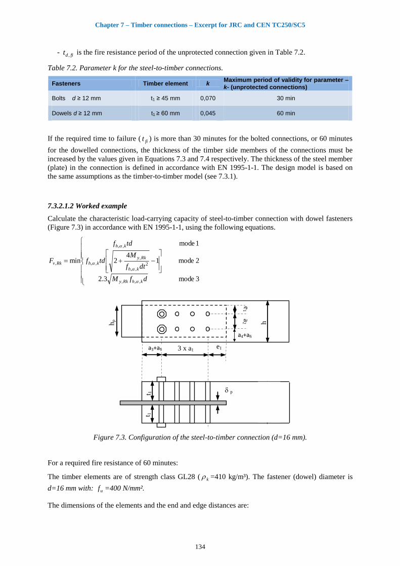
Chapter 7 – Timber connections – Excerpt for JRC and CEN TC250/SC5
134
- fidt , is the fire resistance period of the unprotected connection given in Table 7.2.
Table 7.2. Parameter k for the steel-to-timber connections.
Fasteners Timber element k Maximum period of validity for parameter –
k- (unprotected connections)
Bolts d ≥ 12 mm t1 ≥ 45 mm 0,070 30 min
Dowels d ≥ 12 mm t1 ≥ 60 mm 0,045 60 min
If the required time to failure ( fit ) is more than 30 minutes for the bolted connections, or 60 minutes
for the dowelled connections, the thickness of the timber side members of the connections must be
increased by the values given in Equations 7.3 and 7.4 respectively. The thickness of the steel member
(plate) in the connection is defined in accordance with EN 1995-1-1. The design model is based on
the same assumptions as the timber-to-timber model (see 7.3.1).
7.3.2.1.2 Worked example
Calculate the characteristic load-carrying capacity of steel-to-timber connection with dowel fasteners
(Figure 7.3) in accordance with EN 1995-1-1, using the following equations.
3 mode3.2
2 mode14
2
1 mode
min
,,,
2,,
,
,,
,,
,
dfM
dtf
Mtdf
tdf
F
khRky
kh
Rky
kh
kh
Rkv
(a) Essais au feu (b) Essais à froid
h
a3 e1 3 x a1
e1
t 1
t 1 p
a2 h
p
t 2
3 x a1 a3 e1
h hp a
2 e
1
e = 2 mm
p
t 1
t 1
t 2
a4+afi
a3+afi
Figure 7.3. Configuration of the steel-to-timber connection (d=16 mm).
For a required fire resistance of 60 minutes:
The timber elements are of strength class GL28 ( k =410 kg/m³). The fastener (dowel) diameter is
d=16 mm with: uf =400 N/mm².
The dimensions of the elements and the end and edge distances are:
Chapter 7 – Timber connections – Excerpt for JRC and CEN TC250/SC5
135
t1=76 mm, h=252 mm, p =8 mm and hp=114 mm.
a1=7d, a2=4d, a3=7d, a4=3d and e1=25 mm
The distances a3 and a4 are increased by: )( , fidfifluxnfi ttka
fidt , : for the connection using a combination of dowel and bolt fasteners, the value taken into account
is equal to 15.
The connection is loaded in tension parallel to grain ( 0 ) and the embedment strength of timber
( khf ,0, ) is calculated according to the following formula:
kkh df )01,01(082,0,0,
The characteristic values for yield moment is calculated according to the following formula:
6,2k,uRk,y df3,0M
The characteristic load-carrying capacity of the steel-to-timber connection, in cold conditions, is
calculated according to Equation 7.5. Its value is RkvF , =274 kN.
For this connection, as fitke
=
60045,0 e =0,0672, the design value of the load-bearing capacity
F fitd ,, is given by: 4,182740672,0,, F fitd kN.
For this connection, in order to obtain a fire resistance of R60, it is possible to apply a load fidE ,
lower than or equal to 18,4 kN ( fitdfid FE ,,, ).
fidE , is the design effect of actions in fire situation.
7.3.2.2 Steel-to-timber connection with two or three slotted-in steel plates and dowels
7.3.2.2.1 Introduction
An analytical design model for calculation of the load-carrying capacity in fire of unprotected
multiple-shear steel-to-timber dowelled connections was developed in the same way as for the
reduced cross-section method given in EN 1995-1-2, and based on a combination of experimental and
numerical analysis [7.3-7.5]. The model is based on Failure Mode I according to the Johansen yield
model (i.e. embedment failure) and takes into account the influence of the steel elements (i.e. steel
plates and steel dowels) on the charring of the connection. The model was developed for a fire
resistance up to 60 minutes.
The effective cross-section is calculated by reducing the initial cross-section by the effective charring
depth (def), as shown in Figure 7.4. The temperature-dependent reduction of strength and stiffness of
timber in the heat-affected zones as well as the effects of corner roundings are considered by adding a
further layer (dred) to the charring depth (dchar). For simplicity, the same value of (dred) is used for
charring on side (index - s) and on top/bottom (index - o).
redscharsef ddd ,, (7.5)
redocharoef ddd ,, (7.6)
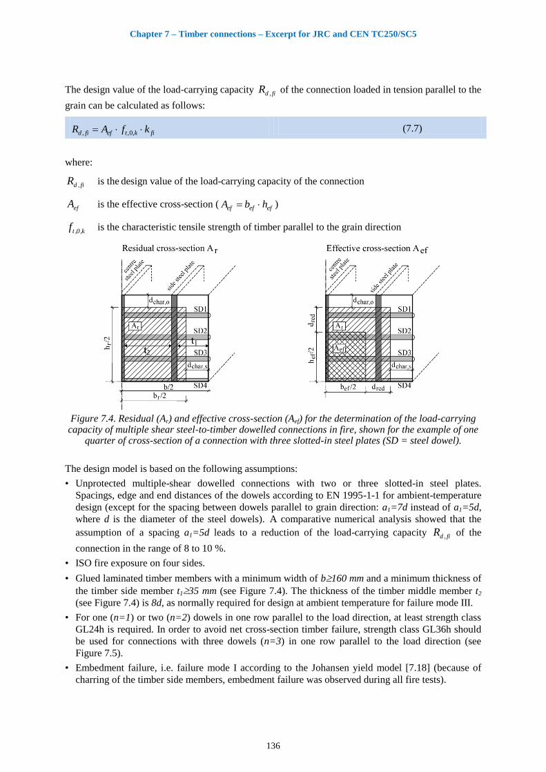
Chapter 7 – Timber connections – Excerpt for JRC and CEN TC250/SC5
136
The design value of the load-carrying capacity fi,dR of the connection loaded in tension parallel to the
grain can be calculated as follows:
fikteffid kfAR ,0,, (7.7)
where:
fi,dR is the design value of the load-carrying capacity of the connection
efA is the effective cross-section ( efefef hbA )
k,0,tf is the characteristic tensile strength of timber parallel to the grain direction
Figure 7.4. Residual (Ar) and effective cross-section (Aef) for the determination of the load-carrying
capacity of multiple shear steel-to-timber dowelled connections in fire, shown for the example of one quarter of cross-section of a connection with three slotted-in steel plates (SD = steel dowel).
The design model is based on the following assumptions:
• Unprotected multiple-shear dowelled connections with two or three slotted-in steel plates.
Spacings, edge and end distances of the dowels according to EN 1995-1-1 for ambient-temperature
design (except for the spacing between dowels parallel to grain direction: a1=7d instead of a1=5d,
where d is the diameter of the steel dowels). A comparative numerical analysis showed that the
assumption of a spacing a1=5d leads to a reduction of the load-carrying capacity fi,dR of the
connection in the range of 8 to 10 %.
• ISO fire exposure on four sides.
• Glued laminated timber members with a minimum width of b160 mm and a minimum thickness of
the timber side member t135 mm (see Figure 7.4). The thickness of the timber middle member t2
(see Figure 7.4) is 8d, as normally required for design at ambient temperature for failure mode III.
• For one (n=1) or two (n=2) dowels in one row parallel to the load direction, at least strength class
GL24h is required. In order to avoid net cross-section timber failure, strength class GL36h should
be used for connections with three dowels (n=3) in one row parallel to the load direction (see
Figure 7.5).
• Embedment failure, i.e. failure mode I according to the Johansen yield model [7.18] (because of
charring of the timber side members, embedment failure was observed during all fire tests).
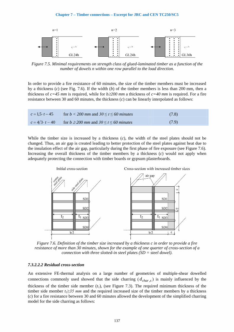
Chapter 7 – Timber connections – Excerpt for JRC and CEN TC250/SC5
137
Figure 7.5. Minimal requirements on strength class of glued-laminated timber as a function of the number of dowels n within one row parallel to the load direction.
In order to provide a fire resistance of 60 minutes, the size of the timber members must be increased
by a thickness (c) (see Fig. 7.6). If the width (b) of the timber members is less than 200 mm, then a
thickness of c=45 mm is required, while for b200 mm a thickness of c=40 mm is required. For a fire
resistance between 30 and 60 minutes, the thickness (c) can be linearly interpolated as follows:
455,1 tc for b < 200 mm and 30 ≤ t ≤ 60 minutes (7.8)
4034 tc for b 200 mm and 30 ≤ t ≤ 60 minutes (7.9)
While the timber size is increased by a thickness (c), the width of the steel plates should not be
changed. Thus, an air gap is created leading to better protection of the steel plates against heat due to
the insulation effect of the air gap, particularly during the first phase of fire exposure (see Figure 7.6).
Increasing the overall thickness of the timber members by a thickness (c) would not apply when
adequately protecting the connection with timber boards or gypsum plasterboards.
Figure 7.6. Definition of the timber size increased by a thickness c in order to provide a fire
resistance of more than 30 minutes, shown for the example of one quarter of cross-section of a connection with three slotted-in steel plates (SD = steel dowel).
7.3.2.2.2 Residual cross-section
An extensive FE-thermal analysis on a large number of geometries of multiple-shear dowelled
connections commonly used showed that the side charring ( s,chard ) is mainly influenced by the
thickness of the timber side member (t1), (see Figure 7.3). The required minimum thickness of the
timber side member t1≥35 mm and the required increased size of the timber members by a thickness
(c) for a fire resistance between 30 and 60 minutes allowed the development of the simplified charring
model for the side charring as follows:
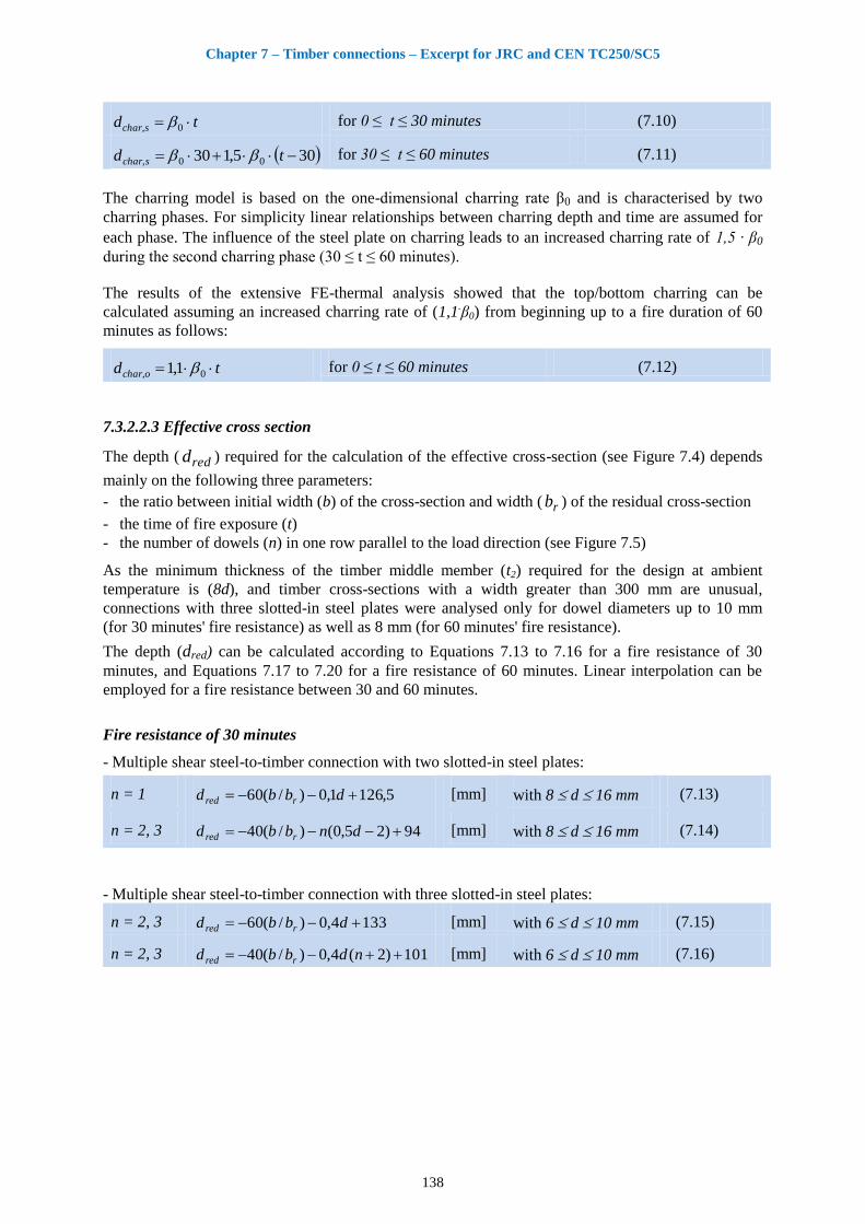
Chapter 7 – Timber connections – Excerpt for JRC and CEN TC250/SC5
138
td schar 0, for 0 ≤ t ≤ 30 minutes (7.10)
305,130 00, td schar for 30 ≤ t ≤ 60 minutes (7.11)
The charring model is based on the one-dimensional charring rate β0 and is characterised by two
charring phases. For simplicity linear relationships between charring depth and time are assumed for
each phase. The influence of the steel plate on charring leads to an increased charring rate of 1,5 ∙ β0
during the second charring phase (30 ≤ t ≤ 60 minutes).
The results of the extensive FE-thermal analysis showed that the top/bottom charring can be
calculated assuming an increased charring rate of (1,1.β0) from beginning up to a fire duration of 60
minutes as follows:
td ochar 0, 1,1 for 0 ≤ t ≤ 60 minutes (7.12)
7.3.2.2.3 Effective cross section
The depth ( redd ) required for the calculation of the effective cross-section (see Figure 7.4) depends
mainly on the following three parameters:
- the ratio between initial width (b) of the cross-section and width ( rb ) of the residual cross-section
- the time of fire exposure (t)
- the number of dowels (n) in one row parallel to the load direction (see Figure 7.5)
As the minimum thickness of the timber middle member (t2) required for the design at ambient
temperature is (8d), and timber cross-sections with a width greater than 300 mm are unusual,
connections with three slotted-in steel plates were analysed only for dowel diameters up to 10 mm
(for 30 minutes' fire resistance) as well as 8 mm (for 60 minutes' fire resistance).
The depth (dred) can be calculated according to Equations 7.13 to 7.16 for a fire resistance of 30
minutes, and Equations 7.17 to 7.20 for a fire resistance of 60 minutes. Linear interpolation can be
employed for a fire resistance between 30 and 60 minutes.
Fire resistance of 30 minutes
- Multiple shear steel-to-timber connection with two slotted-in steel plates:
n = 1 5,1261,0)/(60 dbbd rred [mm] with 8 d 16 mm (7.13)
n = 2, 3 94)25,0()/(40 dnbbd rred [mm] with 8 d 16 mm (7.14)
- Multiple shear steel-to-timber connection with three slotted-in steel plates:
n = 2, 3 1334,0)/(60 dbbd rred [mm] with 6 d 10 mm (7.15)
n = 2, 3 101)2(4,0)/(40 ndbbd rred [mm] with 6 d 10 mm (7.16)
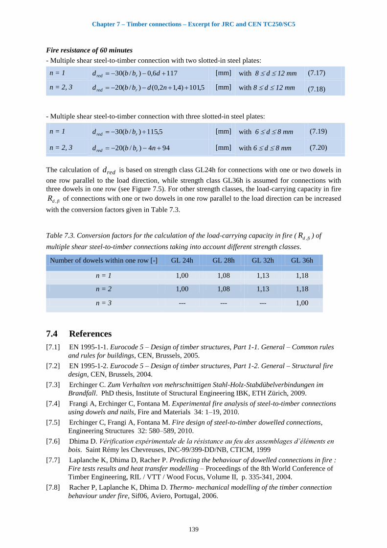
Chapter 7 – Timber connections – Excerpt for JRC and CEN TC250/SC5
139
Fire resistance of 60 minutes
- Multiple shear steel-to-timber connection with two slotted-in steel plates:
n = 1 1176,0)/(30 dbbd rred [mm] with 8 d 12 mm (7.17)
n = 2, 3 5,101)4,12,0()/(20 ndbbd rred [mm] with 8 d 12 mm (7.18)
- Multiple shear steel-to-timber connection with three slotted-in steel plates:
n = 1 5,115)/(30 rred bbd [mm] with 6 d 8 mm (7.19)
n = 2, 3 944)/(20 nbbd rred [mm] with 6 d 8 mm (7.20)
The calculation of redd is based on strength class GL24h for connections with one or two dowels in
one row parallel to the load direction, while strength class GL36h is assumed for connections with
three dowels in one row (see Figure 7.5). For other strength classes, the load-carrying capacity in fire
fi,dR of connections with one or two dowels in one row parallel to the load direction can be increased
with the conversion factors given in Table 7.3.
Table 7.3. Conversion factors for the calculation of the load-carrying capacity in fire ( fi,dR ) of
multiple shear steel-to-timber connections taking into account different strength classes.
Number of dowels within one row [-] GL 24h GL 28h GL 32h GL 36h
n = 1 1,00 1,08 1,13 1,18
n = 2 1,00 1,08 1,13 1,18
n = 3 --- --- --- 1,00
7.4 References
[7.1] EN 1995-1-1. Eurocode 5 – Design of timber structures, Part 1-1. General – Common rules
and rules for buildings, CEN, Brussels, 2005.
[7.2] EN 1995-1-2. Eurocode 5 – Design of timber structures, Part 1-2. General – Structural fire
design, CEN, Brussels, 2004.
[7.3] Erchinger C. Zum Verhalten von mehrschnittigen Stahl-Holz-Stabdübelverbindungen im
Brandfall. PhD thesis, Institute of Structural Engineering IBK, ETH Zürich, 2009.
[7.4] Frangi A, Erchinger C, Fontana M. Experimental fire analysis of steel-to-timber connections
using dowels and nails, Fire and Materials 34: 1–19, 2010.
[7.5] Erchinger C, Frangi A, Fontana M. Fire design of steel-to-timber dowelled connections,
Engineering Structures 32: 580–589, 2010.
[7.6] Dhima D. Vérification expérimentale de la résistance au feu des assemblages d’éléments en
bois. Saint Rémy les Chevreuses, INC-99/399-DD/NB, CTICM, 1999
[7.7] Laplanche K, Dhima D, Racher P. Predicting the behaviour of dowelled connections in fire :
Fire tests results and heat transfer modelling – Proceedings of the 8th World Conference of
Timber Engineering, RIL / VTT / Wood Focus, Volume II, p. 335-341, 2004.
[7.8] Racher P, Laplanche K, Dhima D. Thermo- mechanical modelling of the timber connection
behaviour under fire, Sif06, Aviero, Portugal, 2006.
Chapter 7 – Timber connections – Excerpt for JRC and CEN TC250/SC5
140
[7.9] Laplanche K, Dhima D, Racher P. Thermo-mechanical analysis of the timber connection
under fire using 3D, WCTE06, Portland, 2006.
[7.10] Laplanche K. Etude du comportement au feu des assemblages de structures bois : Approche
expérimentale et modélisation, PhD Thesis, 19 juillet 2006.
[7.11] Racher P, Laplanche K, Dhima D, Bouchaïr A. Thermo- mechanical analysis of the fire
performance of dowelled timber connection. Engineering Structures (2010),
doi:10.1016/j.engstruct.2009.12.041.
[7.12] Cachim P B, Franssen J-M. Numerical modelling of timber connections under fire loading
using a component model, Fire safety journal, 2009.
[7.13] Cachim P B, Franssen J-M. Timber connections under fire loading, a component model for
numerical modelling, Application of structure Fire Engineering, 19-20 February 2009,
Prague, Czech Republic.
[7.14] Fornather J, Bergmeister K and Hartl H. Fire behaviour of steel and fasteners in wood
composites, RILEM Symposium Joints in Timber Structures, Stuttgart, pp 619-628, 2001.
[7.15] Fornather J H. Brandverhalten von Holtz unter besonderer Berücksichtigung stiftförmiger
Verbindungsmittel – experimentelle und numerische Untersuchungen, PhD thesis, Wien,
2003.
[7.16] Povel D. Tragfähigkeit von Holzverbindungen mit stabförmigen Verbindungsmitteln im
Brandfall. (Load-bearing capacity of timber connections with dowel-type fasteners in case of
fire). Doktorarbeit von der Fakultät IV Bauingenieurwesen und Angewandte Geowissen-
schaften der Technischen Universität Berlin zur Erlangung des akademischen Grades, 2002.
[7.17] Norén J. Load-bearing of nailed joints exposed to fire, Fire and Materials. 1996; Vol. 20, pp
133-143, 1996.
[7.18] Johansen K W. Theory of Timber Connections, Forest Products Journal, Vol.25, N°2, pp 249 -
262, 1949.
[7.19] Lau P H. Fire resistance of connections in laminated veneer lumber. PhD thesis Canterbury
University, New Zealand, 2006.
[7.20] Chuo T, Chung B. Fire resistance of connections in laminated veneer lumber. PhD thesis
Canterbury University, New Zealand, 2006.
[7.21] Dhima D, Bouchaïr A, Frangi A. Fire-safe use of wood in building, Timber connection, 2nd
draft, 28 august 2009. Study realised for CEI – Bois roadmap.


