
IRIE 1
Flare-Shaped Revetments: installation experience&
results on sensitivity of design to climate change
lsao lrie, Tokyo CoDoo, (IDEA Consultants, lnc.), [email protected] i h i ro Hamazaki, (KOBE STEE L, LTD), hamazaki.yos h i h [email protected] ke M urakami, (U n iversity of miyazaki), keis [email protected] iyazaki-u.ac j pTomotoki Toyoda, (ATSC lnc.), [email protected]
lntroductionThe safety of water front will be highly upgraded if no wave overtopping is expected even onrough sea. This paper presents on the development and installation experience of Flare-Shaped Revetments (Flare-Shaped Stmctures) with no wave overtopping, and also the resultson sensitivity of design to climate change. Most of the existing coastal protective structuresare designed by the expected overtopping rate method, for instance, obtaining the timeaveraged overtopping rate for Rayleigh distributed waves. Actual coastal waves, however,include wave groups composed of high waves and unexpected high rate of overtopping can besometimes observed. When the landward spaces are utilized by more fragile objects such aswalkers, automobiles, and residences, those exceptionally high wave overtopping is notallowed, and some devices on the performance of structures have been required.
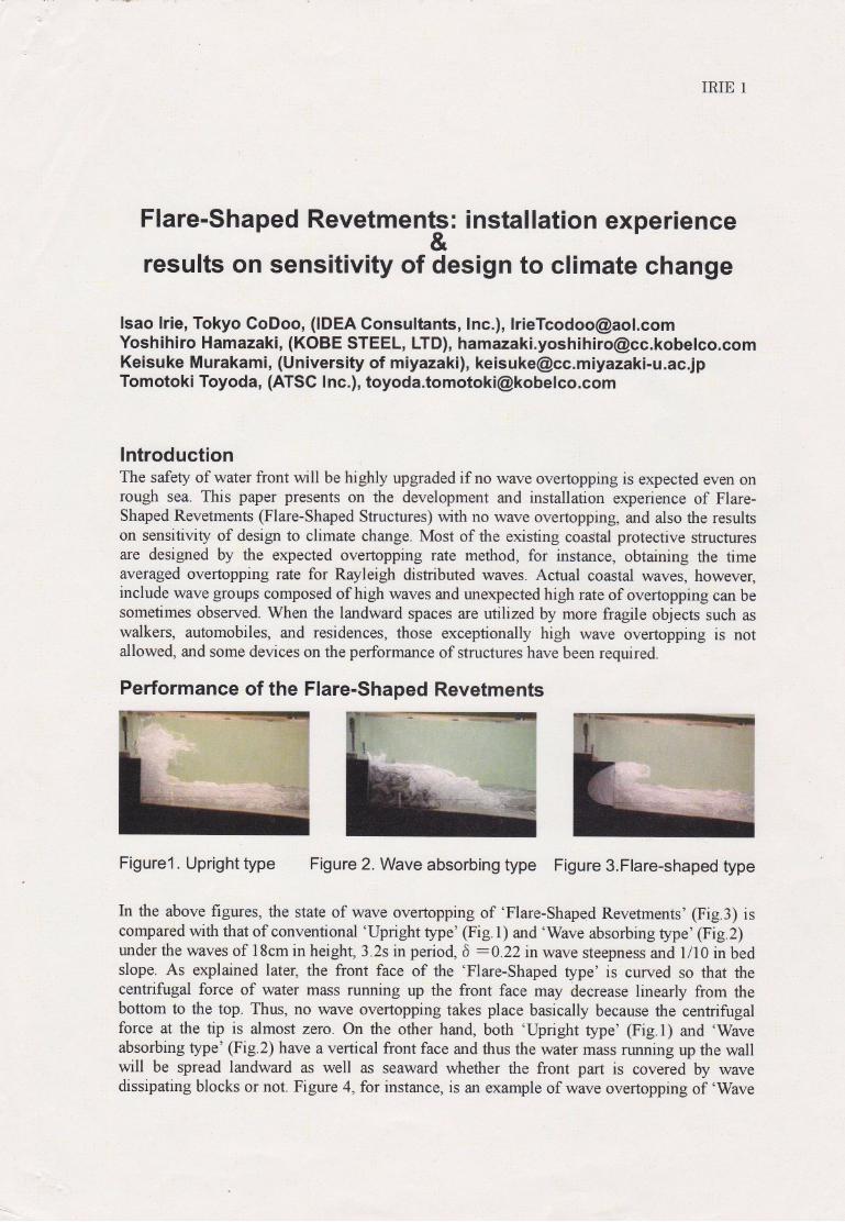
Performance of the Flare-Shaped Revetments
Figurel. Upright type Figure 2. Wave absorbing type Figure 3.Flare-shaped type
In the above figures, the state of wave overtopping of 'Flare-Shaped Revetments' (Fig.3) iscompared with that of conventional 'Upright type' (Fig.1) and 'Wave absorbing type' (Fig.2)under the waves of l8cm in height, 3.2s in period, 6 :0.22 in wave steepness and l/10 in bedslope. As explained later, the front face of the 'Flare-Shaped type' is curved so that thecentrifugal force of water mass running up the front face may decrease linearly from thebottom to the top. Thus, no wave overtopping takes place basically because the centrifugalforce at the tip is almost zero. on the other hand, both'Upright type'(Fig.l) and'Waveabsorbing type' (Fig.2) have a vertical front face and thus the water mass running up the wallwill be spread landward as well as seaward whether the front part is covered by wavedissipating blocks or not. Figure 4, for instance, is an example of wave overtopping of 'Wave
IRIE 2
absorbing type' in the field and this type of overtopping is frequently seen on many roads,where the emergency waming, 'Close to traffic'is given.
Figure4. Wave absorbing type FigureS.Offshore casting, Flare-shaped
Figure 5 shows how the 'Flare-Shaped type' protects from wave overtopping: all the watermass running up is thrown back to offshore, securing the high level safety of hinter land.
Designing the Flare-Shaped Revetments
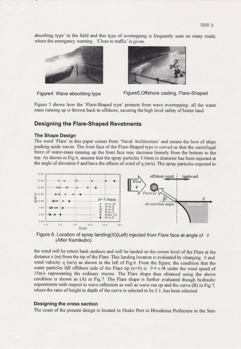
The Shape DesignThe word 'Flare' in this paper comes from 'Naval Architecture' and means the bow of shipspushing aside waves. The front face of the Flare-Shaped type is curved so that the centrifugalforce of water-mass running up the front face may decrease linearly from the bottom to thetop. As shorvn in Fig.6, assume that the spray particles 5.Omm in diameter has been injected atthe angle of elevation 0 and have the effects of wind of q (m/s). The spray particles exposed to
3 0.00
25.00
20.00
?rs oo
!1 r o.oo
500
0.00
- 5.00
rlllttl.-.---.------oi--.a...--.......itr-...-----....io- x.--...--o--tlrlllrlllrill
trirrrirll
o 0=n /12A 0 --tt /6tr 0=n/4o 0=n/3X 0--5n /12o 0--n /2
offshore ward i landward:
-5.0 10 05.000 15.0 20.0
X(m)
Figure 6. Location of spray landing(X)(Left) injected frorn Flare face at angle of 0(After Kamikubo)
the wind will be retum back onshore and will be landed on the crown level of the Flare at thedistance x (m) from the tip of the Flare. This landing location is evaluated by changing g andwind velociry q (n/9 as shown in the left of Fig.6. From the figure, the condition that thewater particles fall offshore side of the Flare tip (x=0) is 0 = n 14 under the wind speed ofl5m/s representing the ordinary storms. The Flare shape thus obtained using the abovecondition is shorvn as (A) in Fig.7. The Flare shape is further evaluated though hydraulicexperiments with respect to wave reflection as well as wave run up and the curve @) inEig.7,where the ratio of height to depth of the curve is selected tobe 2'.1, has been selected.
Designing the cross sectionThe coast of the present design is located in Osako Port in Hiroshima Prefecture in the Seto
An ejection angle
IRIE 3
Inland Sea. It was hit by heavy typhoon two times (in 1999 and 2004) and the coastal areawas suffered by heavy wave overtopping. Various reconstruction measures including waveabsorbing revetments as well as offshore breakwaters were reviewed and finally, Flare-shapedRevetments were selected because of lower crown height, keeping good view and especiallylow cost. The present paper introduces the major points of designing.
rf)()c?
-ora
b0I
N
uN 0.10
1 .E-02
1 .E-03
1 .E-04
1 .E-05
00 0.05 0.10 0.15 0.20
X(m)
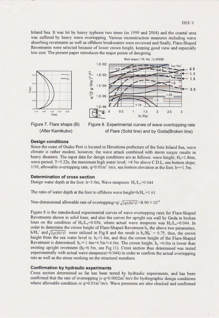
Fig ure 7 . Flare shape (B)
(After Kamikubo)
Figure 8. Experimental
of Flare (Solid
1.E-06
Kil?,='
Bed slopel/10, Ho' /L=0.036
0.5l. r0
1.5
2.0
1 1.5 2 2.5 3
h/Ho'
curves of wave overtopping rate
line) and by Goda(Broken line)
Design conditionsSince the coast of Osako Port is located in Hiroshima prefecture of the Seto Inland Se4 waveclimate is rather modest, howeveq the wave attack combined with storm surges results inheavy disasters. The input data for design conditions are as follows: wave height; IIo:1.86m,wave period;T:5.22s, the muximum high-water level; +4.5m above C.D.L, sea bottom slope;1/10, allowable overtoppingrate; q:0.01m3 /rnls, sea bottom elevation at the foot; h:fl.Sm.
Determination of cross sectionDesign water depth at the foot: h:3.0m, Wave steepness: HJL":O.044
The ratio of water depth at the foot to offshore wave heighFh/Il"':1.61
Non-dimensional allowable rate of overtopping=ql Jrg(Ho')z:8.90 X l0-o
Figure 8 is the standardized experimental curves of wave overtopping rates for Flare-ShapedRevetments shown in solid lines, and also the curves for upright sea wall by Goda in brokenlines on the condition of rt/L.=0.036, where actual wave steepness was H"/L.:0.044. Inorder to determine the crown height of Flare-Shaped Revetment ho,the above two parameters,hlIJ.' andJzs@o')3 were utiliz"a itt fig.A and the result is h"l4' = 0.75, thus, the crownheight from the sea water level is: ho:1.4m, and thus the crovm height of the Flare-ShapedRevetment is determined: fu: l.4m+4.5m=6.0m. The crovm height, ho =6.0m is lower thanexisting upright revetment (16:6.5m, see Fig.ll). Cross section thus determined was testedexperimentally with actual wave steepness(:0.044) in order to confirm the actual overtoppingrate as well as the stress working on the structural members.
Confirmation by hydraulic experimentsCross section determined so far has been tested by hydraulic experiments, and has beenconfirmed that the rate of overtopping is q:g.gOOrm'/m/s for hydrographic design conditionswhere allowable condition is q:6.9f -3/m/s. Wave pressures are also checked and confirmed
IRIE 4
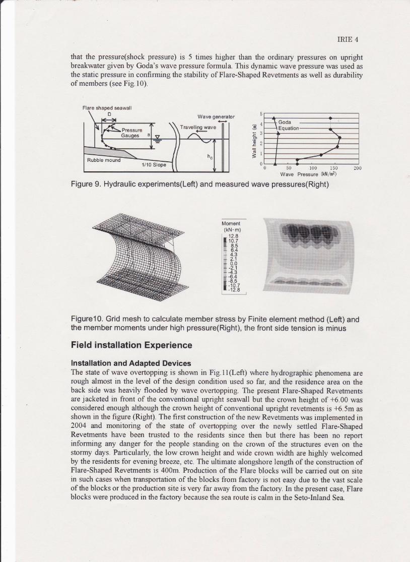
that the pressure(shock pressure) is 5 times higher than the ordinary pressures on uprightbreakwater given by Goda's wave pressure formula. This dynamic wave pressure wzm used asthe static pressure in confirming the stability of Flare-Shaped Revetments as well as durabilityof members (see Fig.l0).
T Goda\ Ea, ,^{i^
\I
I-,---t--<
Y
E4pa-E
!'
u)'il rr-C&:(sr
=10 50 100 150 200
Wave Pressure (kN/mz)
Figure 9. Hydraulic experiments(Left) and measured wave pressures(Right)
Figure10. Grid mesh to calculate member stress by Finite element method (Left) andthe member moments under high pressure(Right), the front side tension is minus
Field installation Experience
lnstallation and Adapted DevicesThe state of wave overtopping is shown in Fig.ll(Left) where hydrographic phenomena zrerough almost in the level of the design condition used so far, and the residence area on theback side was heavily flooded by wave overtopping. The present Flare-Shaped Revetrnentsare jacketed in front of the conventional Wright seawall but the crown height of +6.00 wasconsidered enough although the crown height of conventional upright revetments is +6.5m asshovm in the figure (Rlgh| The first construction of the new Revetments was implemented in2004 and monitoring of the state of overtopping over the newly settled Flare-ShapedRevetments have been trusted to the residents since then but there has been no reportinforming any danger for the people standing on the crown of the structures even on thestormy days. Particularly, the low crown height and wide crown width are highly welcomedby the residents for evening breeze, etc. The ultimate alongshore length of the construction ofFlare-Shaped Revetments is 400m. Production of the Flare blocks will be carried out on sitein such cases when transportation of the blocks from factory is not easy due to the vast scaleof the blocks or the production site is very far away from the factory. In the present case, Flareblocks were produced in the factory because the sea route is calm in the Seto-Inland Sea.
Moment(kN. m)
l*13?iK 8.5l*i 6.4i-; 4.3l+ 2.1l; 0.0l; -2 1
l; -4-:il# -6.4
iffi,?fr
Flare shaped seawall
Pressure
Rubble mound1110 Slope
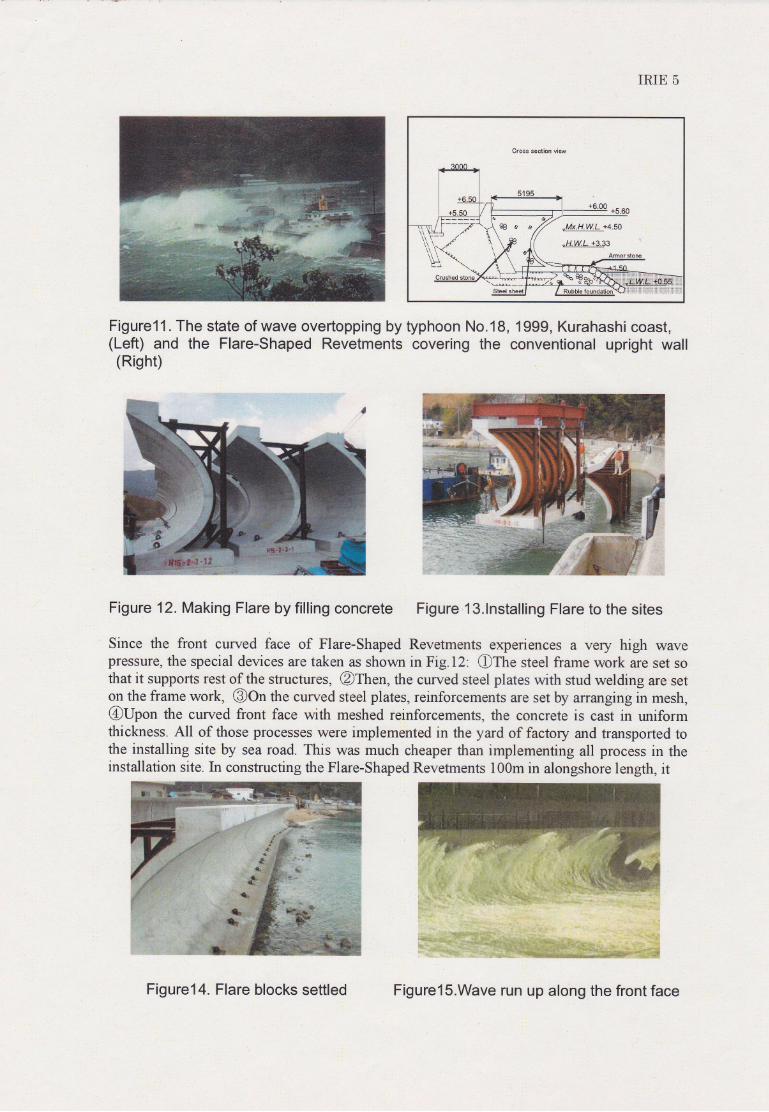
Figurell . The state of wave overtopping by typhoon No.18,(Left) and the Flare-Shaped Revetments covering the(Risht)
IRIE 5
1999, Kurahashi coast,conventional upright wal
Figure 12. Making Flare by filling concrete Figure l3.lnstalling Flare to the sites
Since the front curved face of Flare-Shaped Revetments experiences a very high wavepressure, the special devices are taken as shown in Fig.12: Ofne steel frame work are set sottrat it supports rest of the structures, @Then, the cuwed steel plates with stud welding are seton the frame work, @On the curved steel plates, reinforcements are set fu ananging in mesh,@Upon the curved front face with meshed reinforcements, the concrete is cast in uniformthickness. All of those processes were implemented in the yard of factory and transported tothe installing site by sea road. This was much cheaper than implementing all process in theinstallation site: In constructing the Flare-Shaped Revetments l00m in alongshore length, it
Figure14. Flare blocks settled Figurels.Wave run up along the front face
IRIE 6
took half a yeff in manufacturing all the Flare blocks in the factory and one month ininstalling to the field coast. The standard Flare blocks are 6m inlength, 50 tons in weight, andthus the crane vessels of 160 tons were used. The construction costs of Flare-ShapedRevetments were slightly lower than the conventional type revetments.
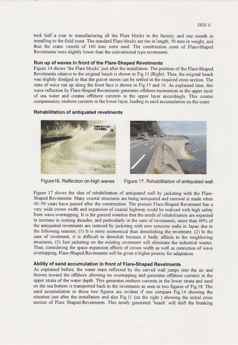
Run up of waves in front of the Flare-Shaped RevetmentsFigure 14 shows 'the Flare blocks' just after the installation. The position of the Flare-ShapedRevetments relative to the original beach is shown in Fig.l I (Rrght). Thus, the original beachwas slightly dredged so that the gravel stones can be settled in the required cross section. Thestate of wave nm up along the front face is shown in Fig.l5 and 16. As explained later, thiswave reflection by Flare-Shaped Revetments generates offshore momentum in the upper layerof sea water and creates offshore currents in the upper layer accordingly. This createscompensatory onshore currents in the lower layer, leading to sand accumulation on the coast.
Rehabilitation of antiquated revetments
Figurel 6. Reflection on Figure 17 , Rehabilitation of antiquated wall
Figure 17 shows the idea of rehabilitation of antiquated wall by jacketing with ttre Flare-Shaped Revetments. Many coastal structures are being antiquated and renewal is made r,vhen40-50 years have passed after the construction. The present Flare-Shaped Revetment has avery wide crowll width and expansion of coastal highway could be realized with high safetyfrom wave overtopping. It is the general notation that the needs of rehabilitation are expectedto increase in coming decades, and particularly in the case of revetments, more than 60% ofthe antiquated revetments are restored by jacketing with new concrete walls in Japan due tothe following reasons; (l) It is more economical than demolishing the revetment, (2) In thecase of revetment, it is difficult to demolish because it badly affects to the neighboringstructures, (3) Just jacketing on the existing revetment will eliminate the industrial wastes.Thus, considering the space expansion effects of crown width as well as restriction of waveovertopping, Flare-Shaped Revetrnents will be given a higher priority for adaptation.
Ability of sand accumulation in front of Flare-Shaped RevetmentsAs explained before, the water mass reflected by the curved wall jumps into the air andthrown toward the offshore allowing no overtopping and generates offshore currents in theupper strata of the water depth. This generates onshore currents in the lower strata and sandon the sea bottom is transported back to the revetments as seen in two figures of Fig.18. Thesand accumulation in those two figures are evident if one compare Fig.l4 showing thesituation just after the installation and also Fig.ll (on the right ) showing the initial crosssection of Flare Shaped-Revetments. This newly generated 'beach' will shift the breaking
IRIE 7
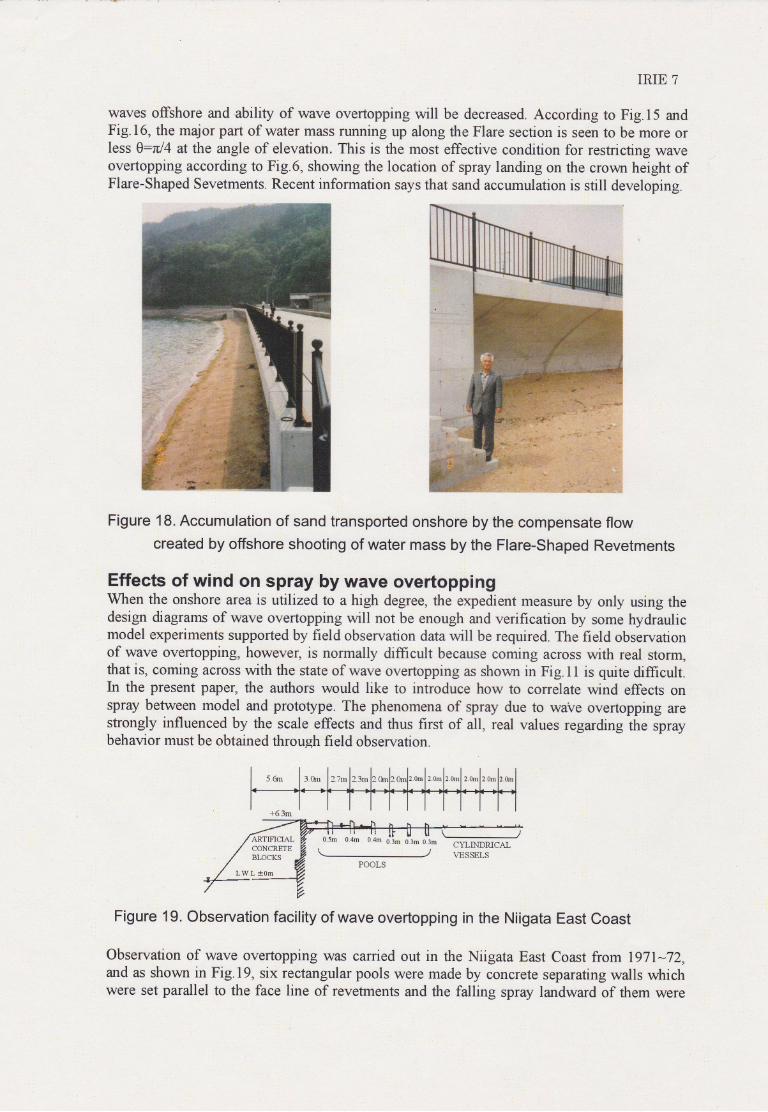
waves offshore and ability of wave overtopping will be decreased. According to Fig.15 andFig.16, the major part of water mass running up along the Flare section is seen to be more orless 0:zrl4 at the angle of elevation. This is the most effective condition for restricting waveovertopping according to Fig.6, showing the location of spray landing on the crown height ofFlare-Shaped Sevetments. Recent information says that sand accumulation is still developing.
Figure 18. Accumulation of sand transported onshore by the compensate flowcreated by offshore shooting of water mass by the Flare-Shaped Revetments
Effects of wind on spray by wave overtoppingWhen the onshore area is utilized to a high degree, the expedient measure by only using thedesign diagrams of wave overtopping will not be enough and verification by some hydraulicmodel experiments supported by field observation data will be required. The field obslrvationof wave overtopping, however, is normally diffrcult because coming across with real storm,that is, coming across with the state of wave overtopping as shown in Fig.l I is quite difficult.In the present paper, the authors would like to introduce how to correlate wind effects onspray between model and prototype. The phenomena of spray due to waVe overtopping arestrongly influenced by the scale effects and thus first of all, real values regarding the spraybehavior must be obtained through field observation.
Figure 19. Observation facility of wave overtopping in the Niigata East Coast
Observation of wave overtopping was carried out in the Niigata East Coast from l97I*72,and as shovm in Fig.l9, six rectangular pools were made by concrete separating walls whichwere set parallel to the face line of revetments and the falling spray landward of them were
ARTIFICIALCONCRETEsLOcKs
L.W.L t0m
o.4m g3p1 o.3m 0.3m
IRIE 8
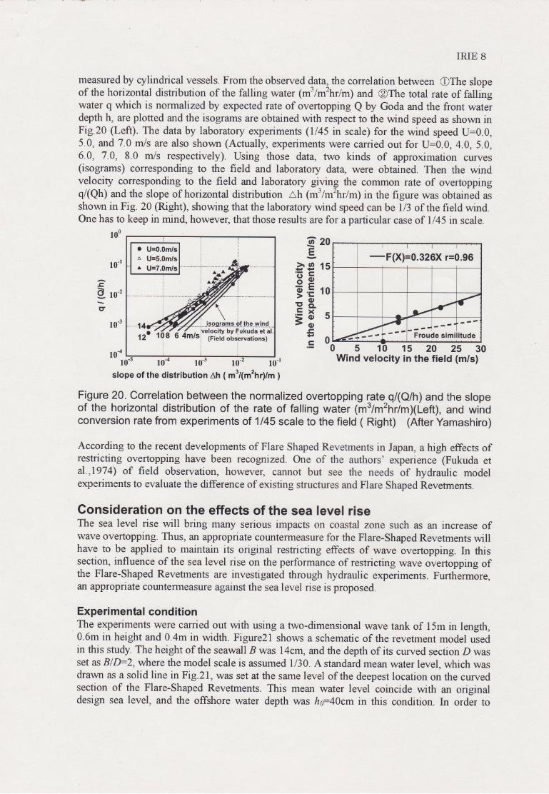
measured by cylindrical vessels. From the observed data, the correlation between OThe slopeof the horizontal distribution of the falling water (mlm2hr/m) and @The total rate of fallingwater q which is normalized by expected rate of overtopping Q by Goda and the front wateidepth h, are plotted and the isograms are obtained with respect to the wind speed as shown inFig.20 (Left). The data by laboratory experiments (l/45 in scale) for the wind speed U=0.0,5.0, and 7.0 mls are also shor,vn (Actually, experiments were carried out for U:0.0, 4.0, 5.0,6.0,7.0,8.0 m/s respectively). Using those data, two kinds of approximation curves(isograms) corresponding to the field and laboratory dat4 were obtained. Then the windvelocity corresponding to the field and laboratory glving the common rate of overtoppingq(Qh) and the slope of hoimntal distribution ah (mlm2hrlm) in the figure was obtained asshovm in Fig. 20 (Right), showing that the laboratory wind speed can be 1/3 of the field wind.One has to keep in mind, however, that those results are for a particular case of l/45 in scale.
100
10-r
20
15
10
Ao\E
U'
>o+. *ra'F6V.-
I Lo.=:b9CLLX
=oalo?-{r,,=
AF-g 1o-2
\,r
cr
10-3
05Wind velocity
1 15 20 25 30in the field (m/s)10-4
10 10 10-3 10- 10-r
slope of the distribution ltr 1m34m2trrym ;
Figure 20. Correlation between the normalized overtopping rate q/(Q/h) and the slopeof the horizontal distribution of the rate of falling water 1m3/m2nrlm)(Left), and windconversion rate from experiments of 1/45 scale to tf," field ( Right) lAtter iamashiro)
According to the recent developments of Flare Shaped Revetments in Japan, a high effects ofrestricting overtopping have been recognized. One of the authors' experience (Fukuda eta1.,1974) of field observation, however, cannot but see the needs of hydraulic modelexpefiments to evaluate the difference of existing structures and Flare Shaped Revetments.
Gonsideration on the effects of the sea level riseThe sea level rise will bring many serious impacts on coastal zone such as an increase ofwave overtopping. Thus, an appropriate countermeasure for the Flare-Shaped Revetments willhave to be applied to maintain its original restricting effects of wave overtopping. In thissection, influence of the sea level rise on the performance of restricting wave overtopping ofthe Flare-Shaped Revetments are investigated through hydraulic experiments. Furthirmore,an appropriate countermeasure against the sea level riie is proposed.
Experimental conditionThe experimetts were c#ed out with using a two-dimensional wave tank of 15m in length,0.6m in height and 0.4m in width. Figure2l shows a schematic of the revetment model usedin this study. The height of the seawall B was l4cm, and the depth of its curved section D wasset as BID=2, where the model scale is assumed 1/30. A standard mean water level, which wasdrawn as a solid line in Fig.2l, was set at the same level of the deepest location on the curvedsection of the Flare-Shaped Revetments. This mean water level coincide.with an originaldesign sea level, and the offshore water depth was h640cm in this condition. In order to
EF(X)=Q .326X r=0.96
Froude similitude
IRIE 9
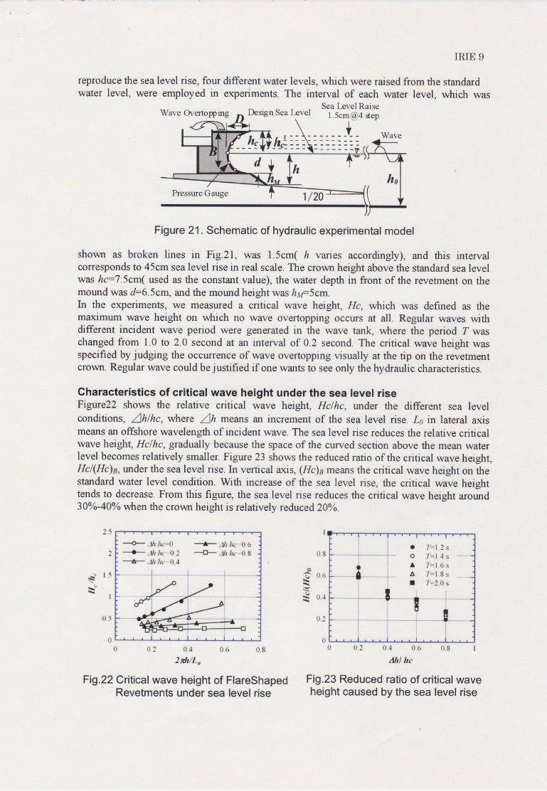
reproduce the sea level rise, four different water levels, which were raised from the standardwater level, were employed in experiments. The interval of each water level, which was
Sea Level RarseWave Overtopprng Design Sea Level l.5cm @4 step
WaveG-
Pressure Gauge1 /20
Figure 21. Schematic of hydraulic experimental model
shovm as broken lines in Fig.2l, was l.5cm( ft varies accordingly), and this intervalcorresponds to 45cm sea level rise in real scale. The crown height above the standard sea levelwas hc=7.5cm( used as the constant value), the water depth in front of the revetment on themound was d:6.5cm, and the mound height was httrScm.In the experiments, we measured a critical wave height, Hc, vilrich was defined as themaximum wave height on which no wave overtopping occurs at all. Regular waves withdifferent incident wave period were generated in the wave tank, where the period Z waschanged from 1.0 to 2.0 second at an interval of 0.2 second. The critical wave height wasspecified by judging the occurrence of wave overtopping visually at the tip on the revetmentcrown, Regular wave could be justified if one wants to see only the hydraulic characteristics.
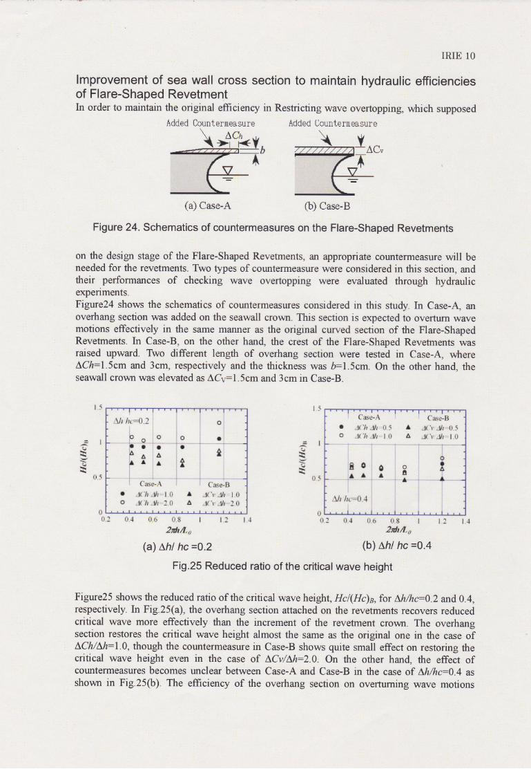
Characteristics of critical wave height under the sea level riseFigure22 shows the relative critical wave height, Hclhc, under the different sea levelconditions, Zhlhc, where Zh means an increment of the sea level ise. Ls in lateral axismeans an offshore wavelength of incident wave. The sea level rise reduces the relative criticalwave height, Hclhc, gradually because the space of the curved section above the mean waterlevel becomes relatively smaller. Figure 23 shows the reduced ratio of the critical wave height,Hc/(Hc)n, under the sea level rise. In vertical axrs, (Hc)a means the critical wave height on thestandard water level condition. With increase of the sea level rise, the critical wave heighttends to decrease. From this figure, the sea level rise reduces the critical wave height around30yo-40yo rryhen the crown height is relatively reduced2}Yo.
--0- *r*{i -F /rr ff,*---{--
"Sr Jir -fi 1 ---{3- Jfi lre', ft S
---*r" #r hr' '# 4
1ilp:
r] fi3 {:,.4 11& i}*2 tdt,tl-,,
Fig .22 Critical wave height of FlareshapedRevetments under sea level rise
25
=? o,rrrhr*i
*ir .l\
; l{s r''i-\l
ri8
* fi.; *,t tl.{l *,8 I
&fr! *r
Fig .23 Reduced ratio of critical waveheight caused by the sea level rise
tr,5 Lt,:
Added tountermeasure
lmprovement ofof Flare-ShapedIn order to maintain
IRIE 10
sea wall cross section to maintain hydraulic efficienciesRevetment
the original efiiciency in Restricting wave overtopping, rarhich supposed
Added Uountermeasure
(a) Case-A (b) Case-B
Figure 24. Schematics of countermeasures on the Flare-Shaped Revetments
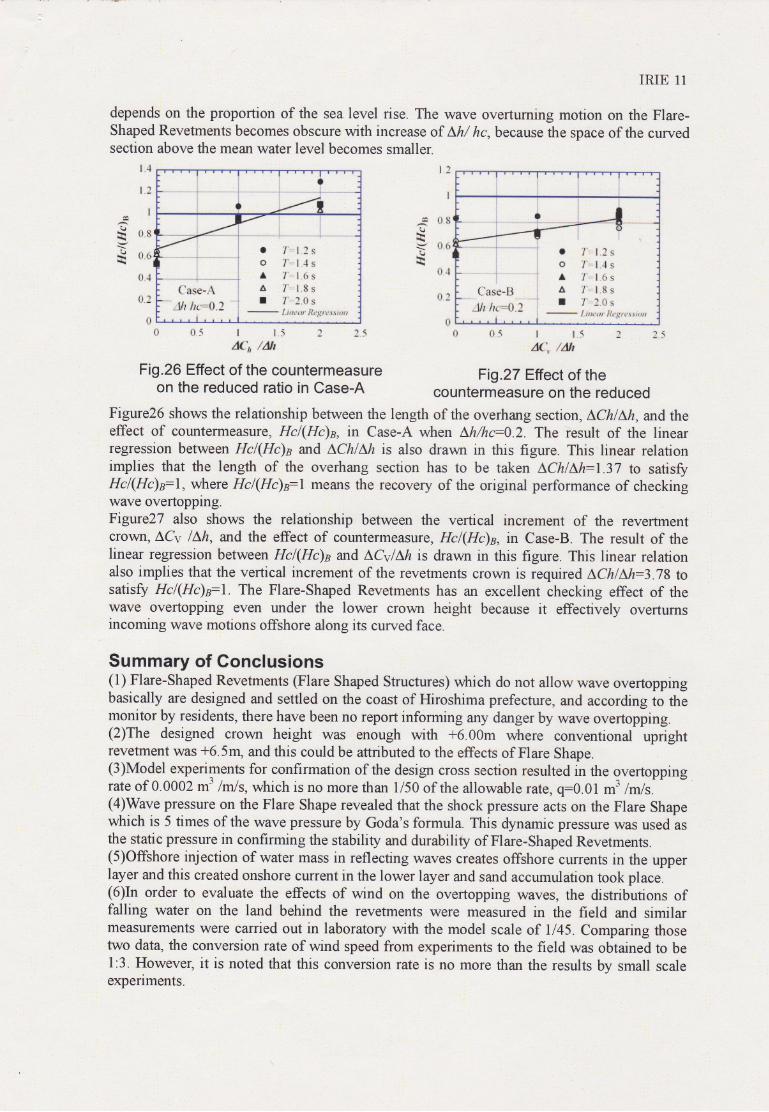
on the design stage of the Flare-Shaped Revetments, an appropriate counterrneasure will beneeded for the revetments. Two types of countermeasure were considered in this section, andtheir perfonnances of checking wave overtopping were evaluated through hydraulicexperiments.Figtxe24 shows the schematics of countermeasures considered in this study. In Case-A, anoverhang section was added on the seawall crown. This section is expected to overtum wavemotions effectively in the same malrner as the original curved section of the Flare-shapedRevetments. In Case-B, on the other hand, the crest of the Flare-Shaped Revetments wasraised upward. TWo different length of overhang section were tested in Case-A, whereLCh:l.Scm and 3cm, respectively and the thickness was b:l.5cm. On the other hand, theseawall crown was elevated as ACv:l.5cm and 3cm in Case-B.
: {'ase-A ' q"fise-B
a Jf 'll Jr #.5 t J{'r.-$r {} 5o J{ ? -f} l (-l A J{'r" __lli I {t
'
,,qffe a o t.-rL t I. I-,
1t, f1.','.,{J.-f i), :.
I
{}'r fi.J {-}.e #. fl I
Atdtfr"o
(a) Lhl hc =0.2
Fig .25 Reduced ratio of the critical wave height
Figure25 shows the reduced ratio of the critical wave height, Hcl(Hc)n,for Lh/hc:o.2 and0.4,respectively. In Fig.25(a), the overhang section attached on the revetments recovers reducedcritical wave more effectively than the increment of the revetment crom. The overhangsection restores the critical wave height almost the same as the original one in the case ofLCh/Lh:|.O, though the countermeasure in Case-B shows quite small effect on restoring thecritical wave height even in the case of LCv/Lh:2.O. On the other hand, the effect ofcountermeasures becomes unclear between Case-A and Case-B in the case of Lh/hc:0.4 asshown in Fig.25(b). The efficiency of the overhang section on overtuming wave motions
4lII
rir\L}\+
{)i
fatAl
'tarl.\\i.l
!rrtrt:1.5
tl {}
i"lt: 14 : 04 *$ $.s I
"Erdtrt",e
(b) Lhl hc =0.4
i
oiiI
I
]t,"- i " . - -
A.I
.
$ll fur'=lJ.J :
;'o^oL'
atln a ,61 l ,li
:: Cnse-A
l J{'Cr "#r0 -l{'ft *lfr
' {"as*-fit J{'r' "l* l *a J{'r' ."Sr : {}
I{t:fi
IRIE 11
depends on the proportion of the sea level rise. The wave overtuming motion on the Flare-Shaped Revetments becomes obscure with increase of Lh/ hc. because the space of the curvedsection above the mean water level becomes smaller.
iti
tl
i tL"*n
i!ta! i r l'" 1,3s:.: i 0 f"-.t"4s:,'i ' 'i * /'.,", l,dr s'
{'flsg*ffi i A T'' l"S sdf l ,,\4 i il 7',.3,{Jsi}/i lre-*{},_ 't n it ' ;'r} 5
, i f-ir*crrr'ft,:,grt,, sr*ff
tr fr5 I 1"5 3 35d{, lAIt
Fig .27 Effect of thecountermeasure on the reduced
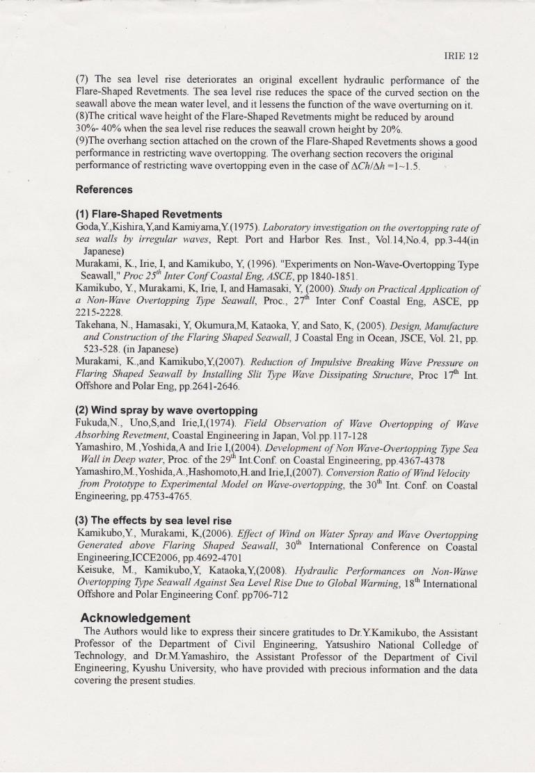
Figure26 shows the relationship between the length of the overhang section, LChlLh, and theeffect of countermeasure, Hcl(Hc)s, in Case-A when Lh/hc:O.2. The result of the linearregression between Hcl(Hc)n and LChIM is also drav,,n in this figure. This linear relafionimplies that the length of the overhang section has to be taken LCh/Lh:1.37 to satisfyHc/(Hc)s:|, where Hcl(Hc)yl means the recovery of the original performance of checkingwave overtopping.Figure2T also shows the relationship between the vertical increment of the revertmentcrown, ACv l\h, and the effect of countermeasure, Hcl(Hc)s, in Case-B. The result of thelinear regression between Hcl(Hc)e and A,CvlM is drawn in this figure. This linear relationalso implies that the vertical increment of the revetments crown is required A^ChlLh:3.78 tosatisfy Hcl(Hc)yL The Flare-Shaped Revetments has an excellent checking effect of thewave overtopping even under the lower crown height because it effectively overtumsincoming wave motions offshore along its curved face.
Summary of Conclusions(1) Flare-Shaped Revetments (Flare Shaped Structures) which do not allow wave overtoppingbasically are designed and settled on the coast of Hiroshima prefecture, and accordi"g io Atmonitor by residents, there have been no report informing any danger by wave overtopping.(2)The designed crowll height was enough with +6.00m where conventional uprightrevetment was +6.5n1 and this could be attributed to the effects of Flare Shape.(3)Model experiments for confirmation of the design cross section resulted in the overtoppingrate of 0.0002 m3 /m/s, which is no more than l/50 of the allowable rate, q:0.01 ni tmts.' -(4)Wave pressure on the Flare Shape revealed that the shock pressure acts on the Flare Shapewhich is 5 times of the wave pressure by Goda's formula. This dynamic pressure was used asthe static pressure in confirming the stability and durability of Flare-Shaped Revetments.(5)Offshore injection of water mass in reflecting waves creates offshore currents in the upperlayer and this created onshore current in the lower layer and sand accumulation took place.(6)In order to evaluate the effects of wind on the overtopping waves, the distributions offalling water on the land behind the revetments were measured in the field and similarmeasurements were carried out in laboratory with the model scale of 1145. Comparing thosetwo dat4 the conversion rate of wind speed from experiments to the field was obtained to bel:3. However, it is noted that this conversion rate is no more than the results by small scaleexperiments.
t"4
[":
t
*"s
t:|'"s
il.-t
t":
.s #s\J
hr*ra
H tl{}U*\
il4
\l\rq
b\J
lri*i
fll
fir]5 | t5 l
rt{'', 'l&tl
Fig .26 Effect of the countermeasureon the reduced ratio in Case-A
IRIE 12
(7) The sea level rise deteriorates an original excellent hydraulic performance of theFlare-Shaped Revetments. The sea level rise reduces the space of the curved section on theseawall above the mean water level, and it lessens the function of the wave overtuming on it.(8)The critical wave height of the Flare-Shaped Revetments might be reduced by around30yo- 40yo when the sea level rise reduces the seawall crown height by 20Yo.(9)The overhang section attached on the crown of the Flare-Shaped Revetments shows a goodperformance in restricting wave overtopping. The overhang section recovers the originalperformance of restricting wave overtopping even in the case of LChlLh:l-1.5.
References
(1 ) Flare-Shaped RevetmentsijodaV,firhir4tand Kamiyam4Y(1975). Laborattory investigation on the overtopping rate ofsea walls by inegular waves, Rept Port and Harbor Res. Inst., Vol.l4,No.4, pp.3-44(in
Japanese)Murakami, K., Irie,.I, -d Kamikubo, Y (1996). "Experiments on Non-Wave-Overtopping Type
Seawall," Proc 25th Inter Conf Coastal Eng, ASCE,pp 1840-1851.Kamikubo, Y, Murakami, I! Irie,I, and Hamasaki, Y, (2000). Study on Practical Application ofa Non-wave overtopping Type seawall, Proc., 2f rnter conf Coastal Eng, ASCE, pp2215-2228.Takehana N., Hamasaki, Y, okumur4lVl, Kataoka X and Sato,I! (2005). Design, Manufacture
and Construction of the Flaring Shaped Seawall, J Coastal Eng in Ocean, JSCE, Vol. 21, pp.523-528. (in Japanese)
Murakami, K.,and Kamikubo,Y,Q007). Reduction of Impulsive Breaking Wave Pressure onFlaring Shaped Senvall by Installing SIit Type Wave Dissipating Structure, Proc 17ft Int.Offshore and Polar Eng, pp.2,641 -2646.
(2) Wind spray by wave overtoppingFukud4N., Uno,s,and rie,r,(1974). Field observation of wave overtopping of waveAbsorbing Revetment, Coastal Engineering in Japan, Vol.pp.llT-128Yamashiro, M.,Yoshid4A and Irie I,(2004). Development of Non Wave-Overtopping Type Sea
wall in Deep water, Proc. of the 29* Int.conf. on Coastal Engineering,pp.4367-4378Yamashiro,M.,Yoshida,A.,Hashomoto,H.and Iie,I,(2007). Conversion Ratio of Wnd Velocityfrom Prototype to Experimental Model on Wave-overtopping, the 30ft Int. Conf. on Coastal
Engineering, pp. 47 53 -47 65.
(3) The effects by sea level riseKamikubo,Y, Murakami, K,(2006). Effect of Wnd. on Water Spray and Wave OvertoppingGenerated above Flaring Shaped Seawall, 30* Intemational Conference on CoastalEngineering,Ic CE2006, pp. 4692-47 0lKeisuke, M., Kamikubo,l Kataok4l(2008). Hydraulic Performances on Non-WaweOvertopping Type Seawall Against Sea Level Rise Due to Global Warming,lSft IntemationalOffshore and Polar Engineering Conf. pp706-712
AcknowledgementThe Authors would like to express their sincere gratitudes to Dr.YKamikubo, the Assistant
Professor of the Department of Civil Engineering, Yatsushiro National Colledge ofTechnology, and Dr.M.Yamashiro, the Assistant Professor of the Department of CivilEngineering, Kyushu University, rryho have provided with precious information and the datacovering the present studies.


