

DOC/CP3/40 April 2012
Other products in the Schiedel Rite-Vent range
The NEW highly insulated twin wall system chimney for stoves.
• Easy twist lock connection
• Effective insulation
• 125-150mm internal diameters
ECO ICIDSingle wall stainless steel connecting flue pipe for use on wood and multi-fuel applications.
• 316L Grade stainless steel
• Available in matt black or steel finish
• 125-150mm internal diameters
• Excellent aesthetics
• Lightweight
PRIMA SMOOTHSingle wall stainless steel flue system.• 80-700mm diameter range.
• Prima Plus 1mm for domestic multi fuel stoves.
• Prima Plus for large residential & commercial condensing gas & oil appliances & chimney relining.
PRIMA PLUS
Twin wall insulated system chimney for gas,oil, wood & multi-fuel appliances & open hearths• Residential & commercial applications.
• 80-705mm internal diameters.
• For atmospheric, condensing & pressure appliances.
• Wet or dry flue & chimney operating conditions.
ICSTwin wall gas venting system.• Residential & small commercial applications.
• 100-150mm internal diameters.
• Gas appliances up to 60kW input.
B VENT HETAS TRAINING COURSESCourses H001-H006 available.• For more information see
www.schiedel.co.uk
Part of the MONIER GROUP
Schiedel Chimney SystemsCrowther EstateWashingtonTyne & Wear NE38 0AQTel. +44 (0)191 416 1150Fax. +44 (0)191 415 [email protected]/rite-vent
FLEX LINERS& FLUE BOXESFor relining existing chimneys to take gas, oil,& multi-fuel appliances including stoves & open fires.
INCLUDING NEW SCREW FIT
ADAPTORS &TERMINALS
UPDATEDRANGE!

2 3
Application
Flexible flue and chimney liners designed for lining an existing flue or chimney.
Wonderflex and Triplelock are single wall stainless steel flexible flue liners designed for atmospheric gas and kerosene appliances where the flue gas temperature does not exceed 260°C. Diameter range Wonderflex 100 - 125mm,Triplelock 100 - 500mm.
TecnoFlex is a twin skin flexible chimney liner designed for gas, oil and multifuel, where the maximum flue gas temperature does not exceed 600°C. Diameter range 80 - 300mm.
Product Description
Single Wall Liners
■ Made from corrosion-resistant 316L stainless steel.
■ Leak resistant construction due to continuous weld(Wonderflex) or dovetail folded seam (Triplelock).
■ Highest corrosion resistance.
■ Deep corrugations for high crush resistance andbetter flexibility when installing.
■ Strong seam construction resists the rigours ofpulling the liner into place during construction.
Twin Wall Liner
■ Both inner and outer layers made from corrosion-resistant 316L stainless steel.904L stainless steel is also available as an option for the extreme conditionsfound with appliances like slumbering stoves.
■ Corrugated outer skin for high crush resistance.
■ Extra smooth inner skin allows for easy drain down of condensates, lessopportunity for soot to collect in the joint area and ease of sweeping .
■ Inner skin remains overlapping to protect the joint from corrosion penetrationeven at minimum bending radius.
■ Inner skin remains smooth and protective even after the rigours of installation.
overlap seam weld dovetail folded triplelock seam
Wonderflex Triplelock
TecnoFlex
direction offlue gas flow
Approvals
Flue Sizing
Wonderflex and Triplelock TecnoFlex
This information and sizes are provided as a nominal guide only. Flue sizing for appliances, particularly commercial/industrialapplications will vary depending on siting details and appliance manufacturer’s instructions and design criteria. These will overridethe sizing guide below and reference must be made to appliance manufacturer.
Flue Size Selection Guide Flue Size Selection Guide
Notes: 1 Subject to appliance manufacturer’s testing criteria.2 Subject to manufacturer’s input rating and chimney height.3 Subject to manufacturer’s output rating and chimney height.4 Min 300mm depending on opening, chimney size and height.S Smokeless fuel only.SC Smokeless fuel or coal.
Gas - Atmospheric Boiler
Input up to 25kw •Input 25kw to 40kw •Input 40kw to 60kw •
Gas - Commercial/
Industrial Boilers
Input up to 50kw to 70kw •2
Gas Fires
‘Radiant’ - BS7977-1 2002 •‘Inset’ - BS7977-1 2002 •1 •1‘Backboiler’ - BS7977-2 2003 •
Gas Water Heaters
Input up to 25kw •Input 25kw to 55kw •Input 55kw to 60kw •Input over 60kw •2
Gas Warm Air Units
Input up to 18kw •Input 18kw to 35kw •Input 35kw to 60kw •Input over 60kw •2
Gas Stove/Cooker •2 •2 •2
Kerosene (28 sec Class C2)
Heating Boiler
Output up to 25kw •Input 25kw to 45kw •Input 45kw to 70kw •
Kerosene Stove/Cooker •3 •3 •3
Kerosene Water Heater
Input up to 41kw •
Kerosene Visual Effect
Stove
Output up to 17kw •3 •3
Gas Boiler - Forced Draught
Input up to 25kw •Input 25kw to 45kw •Input 45kw to 50kw •Input 50kw to 75kw •Input 75kw to 100kw •Input over 100kw • •2
Gas Fires
‘Inset’ to BS7977-1 2002 •1‘Decorative’ to •BSEN 509:2000
Gas Oil (35 sec Class D)
Heating Boiler
Output up to 25kw •Input 25kw to 45kw •Input 45kw to 70kw •Input 70kw to 100kw •Output over 100kw •3 •3 •3
Solid Fuel
Heating Boiler
Output up to 20kw •S •SC
Output 20kw to 30kw •S •SC •SC
Output 30kw to 60kw •SC •SC •SC
Open Fires (Standard opening)
500mm x 550mm
‘Avant Garde’ Feature
Open Fires
Room Heaters
Wood burning Stoves/Cookers.Use only seasoned wood which has been stored 1/2 years in dry conditions.
Inglenook or nonstandard opening.The Cross sectional area of the chimney liner must be a minimum of 15% of the total cross sectional area of the fireplace opening.
180 to400mm
100mm
125mm
150mm
80 to100mm
250 to300mm
130mm
150mm
180mm
200mm
230mm
Notes: 1 Subject to appliance manufacturer’s testing criteria.2 Subject to manufacturer’s input rating and chimney height.3 Subject to manufacturer’s output rating and chimney height.4 Min 300mm depending on opening, chimney size and height.S Smokeless fuel only.SC Smokeless fuel or coal.
200min•
180min•
230min•
•4
•S
•
TecnoFlex is CE certified to EN1856-2 TÜV 0036 CPD 9195 025with designations:
Triplelock is CE certified to EN1856-2 TÜV 0036 CPD 9195 023with designations:
T200 P1 W V2 L50010 OT300 N1 W V2 L50010 O
Applications
Wonderflex is CE certified to EN1856-2 TÜV 0036 CPD 9195 024with designations:
T200 P1 D Vm L50010 OT300 N1 D Vm L50010 O
Applications
T600 N1 W V2 L50012 GT600 N1 W V2 L70012 G
T200 P1 W V2 L50012 OT200 P1 W V2 L70012 O
High Temperature Applications Low Temperature Applications

4 5
System Design
Gas burningInput up to 45kw
Kerosene burningOutput up to 45kw
Gas/Oil burningOutput up to 45kw
Solid Fuel burningOutput up to 45kw
Appliance Chimneys builtbefore 1.2.1966
Chimneys builtafter 1.2.1966
Wonderflex or Triplelock can be used in unlinedchimney
F.G.T. under 260˚
Wonderflex or Triplelock can be used in unlinedchimney & surroundingairspace insulated
TecnoFlex can be used in unlined chimney & surrounding airspace insulated
TecnoFlex can be used in unlined chimney &surrounding airspace insulated & ventilated
Wonderflex or Triplelockcan be used in linedchimney
F.G.T. over 260˚
Wonderflex or Triplelock can be used in linedchimney & surroundingairspace insulated
TecnoFlex can be used in lined chimney & surrounding airspace insulated
TecnoFlex can be used in lined chimney &surrounding airspace insulated & ventilated
Termination methods recommended by BS7566 Part 4
For gas burning installations, a flue terminal is required thatcomplies with section 5 of BS715. Where a proprietaryterminal is not used, the free area of outlet openings on thetermination shall be at least twice the cross sectional area ofthe flue. Outlet openings shall be such that they will admit aball of 6mm diameter but not of 16mm diameter. Theopenings shall be uniformly distributed around the terminal orarranged at two opposite faces. (BS5440 Part I). An approvedterminal should be used to protect the end of the flue. A gasflue terminal must be fitted to an all gas installations of170mm diameter or less.
For oil burning installations, a rain cap or universal terminalmay be used, however, as there is a corrosion risk on suchsystems, regular inspection is recommended.
Multi-fuel Applications, Rain caps and universal terminals are notrecommended for use on solid fuels, as the use of coveredterminals will increase flow resistance and encourage theformation of aggressive condensates and deposits. In someinstances, a terminal incorporating a spark guard may bedemanded to reduce the risk of fire hazard. For all multifuelsystems, regular cleaning is essential to prevent theaccumulation of material which could ignite and create a fire hazard.
Mandatory requirements on acceptable chimney, flexible
liner and appliance combinations.
Building Regulations Document J requires that a flexible flueliner can only be installed completely enclosed inside a masonrychimney. A non masonry enclosure such as timber orplasterboard boxing in is not acceptable.
The type of flue liner permitted depends on the fuel to be used,the type of appliance and the type and year of chimneyconstruction in which it is to be fitted.
Building Regulations Document J, outlines differentrequirements for relining masonry chimneys built before andafter 1st February 1966. This is summarised in the table below.
Uniterm (7T05) orFGC Terminal (7T27)
CementFlaunching
Clamp Plate(7T30)(Not requiredwith Uniterm)
DebrisPlate(0164)
GF Box ForRadiant Fires toBS7977-1 2002(GF7T98)
SUITABLE HEARTH COMPLYINGWITH BUILDINGREGULATIONS
Typical Wonderflex or TriplelockInstallation
WonderflexLiner (8H36)
Re-use of a previously capped or shortened chimney.
The chimney can be reused providing the existing brickwork isinspected to ensure it is in good condition. The chimney can belined with the appropriate liner, ensuring that the liner is usedonly inside the stack. Connection to flue pipe - see Fig.1, or to B Vent (gas), Eco ICID (multifuel) or ICS (multifuel) system canbe made to the appliance/ termination, by using the appropriateconnector inside the chimney, and suitably sealed with firecement. The stack can be extended using ICS, B Vent or Eco ICID depending on the application see Fig.2.
Re-use of a fitted flexible liner when changing the appliance.
Provided the diameter and type of flex is suitable for the newappliance to be fitted and the installer has inspected the linerand is satisfied with its condition the liner can be reused.
However, as the lifespan of the previous appliance and liner maynot be known, it is strongly recommended the old flueliner isremoved, the chimney swept, then a suitable new liner installed.
Use of flue liner on condensing appliances.
TecnoFlex can be used on condensing appliances, which havepressure at the flue outlet of 200Pa maximum. It is necessaryto fit a tee and drain point at the base of the vertical system,adequately supported, and connected to a drainpipe to asuitable drain point.
B Vent 0°-90° Bend(1217)
B Vent 275mm Wall Band(0123)
B Vent 0°-90° Bend(1217)
B Vent 450 Adj. Pipe (0208)
B Vent 450 Pipe(1209)
B Vent 900 Pipe (1202)
Ridge Terminal (0142)or CVTA (0128)
B Vent Ridge TileAdaptor (0135)
Flex to B Ventconnector (1278)
Clamp plate (7730)(not shown)
Typical Condensing Appliance Connection
WonderflexLiner (8H36)
Fig. 1
Fig. 2
Clampplate(7T30)
B Vent pipecontinuing totermination(1202)
INTERNAL STACKcapped off in roof space
Flex to B Ventconnector (1278)
CementFlaunching
Typical StoveInstallation
Prima Smooth or Prima Plus
Top Clamp (4003)This item is used in conjunction with the top plate to secure the liner at the top of the stack.
Top Plate (4002)This item is used in conjunction with the top clamp to support the liner at the top of the stack. Can also be used as a debris plate above the appliance.
Debris Plate
(Top Plate) (4002)
Bottom Support Bracket (4009)To secure the TecnoFlex
TecnoFlex LinerAvailable in cut lengths or packs containing the Top Clamp and Top Plate.
Top Insert (4027)
Terminal(4048)
Pot Hanger(4047)
Screw fit range
of Terminals
Prima Smooth
to TecnoFlex
(Black: PSB0E3)
(Steel Finish: PS0E3)
Prima Plus
to TecnoFlex (S0E3)
Vitreous
to TecnoFlex (4044)
TecnoFlex
to Prima Plus (4040)
Screw fit range
of Adaptors
BOTTOMSUPPORTBRACKET(4009)
FLUE PIPE
DRAINPIPE(by others)
TOP PLATEUSED ASDEBRIS PLATE(4002)
TECNOFLEXADAPTOR(4015)
135° TEEWITH TEE CAP(4001)
APPLIANCE
NEW
NEW

6 7
Wonderflex and Triplelock Accessories
Clamp and Plate
FGC Economy Terminal
Int Ø mm 100 125 150Part No. 7T26100 7T27125 7T28150
Int Ø mm 180 200 225 250 300 350 400Part No. 7T32180 7T33200 7T34225 7T47250 7T48300 7T49350 7T50400
Clamp Plate (2 piece)
Int Ø mm 100 125 150Part No. 7T29100 7T30125 7T31150
Int Ø mm 100 125 150
Debris Plate 0164
This item is used to seal the space between the linerand the chimney at the base of the stack.
Int Ø mm 125
Uniterm Type A 7T05125
This Uniterm assembly is designed to be installed to a potless chimney. (Typical 9”x 9”stack)
Tested and Certified to BS715: 1993
Int Ø mm 125
Uniterm Type B 7T04125
This Uniterm assembly is designed to be installed directly to the top of an existing round chimney pot.
Tested and Certified to BS715: 1993
Cast Aluminium Terminal
Int Ø mm 100 125Part No. 7T16100 7T15125
Int Ø mm 100 125 150 180 225 250 300 350 400
Universal Terminal 7T41
This item is manufactured in accordance with the requirements of BS5440.
Wonderflex and Triplelock Single Wall Liners
Drums
Triplelock is available in drums fordiameters 100, 125, 150, 180, 200,225 and 250mm.
300, 350 and 400mm diameters are only available in 10m lengths.
Drum length 80 metres for 100mm and 125mm, reducing thereafter. See price list for full details.
Packs
Triplelock and Wonderflex are available in packs for 100mm and 125mm diameters in the following lengths:
When ordering state: Product Code / Length Code / Diameter.
e.g. to order an 11m pack of Wonderflex 125mmdiameter complete with clamp plate and terminalthe code would be 9E36125.
9H9G9E
8H8G8E
Wonderflex
Cut length
Cut length & clamp plate only
Cut length, clamp plate & terminal
Triplelock
Cut length
Cut length & clamp plate only
Cut length, clamp plate & terminal
ProductCode
This item is used in conjunction with the top plate to secure the linerat the top of the stack. Can also be used as an intermediate support.
TecnoFlex Twin Wall Liners
Packs containing the cut length with clamp plate and nose cone are also available for 125, 155,180 & 200mm diameters. When ordering state Product Code followed by Diameter. eg. a 12m pack of 155mm TecnoFlex is TPF12155.
TecnoFlex is available for all diameters: 80, 100, 125, 155, 180, 200, 230, 250, & 300 as cutlengths. When ordering state Product Code followed by Diameter. eg. a 9m carton of 180mm TecnoFlex is TPB09180.
TPBTPF
TecnoFlex
Cut length
Cut length, clamp plate & nose cone
ProductCode
Length metres 6 7 8 9 10 11 12 13 14 15
Code 20 23 27 30 33 36 40 43 46 49
Int Ømm 80 100 125 155 180 200 230 250 300
Top Clamp 4003
Int Ømm 125 155 180 200 230 250 300
Top Insert 4027
Int Ømm 180 200
Gather Unit 4033
TecnoFlex Accessories
Int ØmmØD1ØD2
808980
100109100
130/125134130
150/155164150
180189180
200209200
230239230
250259250
300309300
Adaptor - Prima Plus to TecnoFlex
Int ØmmØD1ØD2
808980
100109100
130/125134130
150/155164150
180189180
200209200
230239230
250259250
300309300
Adaptor - TecnoFlex to Prima Plus
Int ØmmØD1ØD2
808979
10010999
125134134
155164154
180189179
200209199
230239229
250259249
300309299
Adaptor - TecnoFlex to TecnoFlex
Int ØmmØD1
8089
100109
125134
155164
180189
200209
Nose Cone
Int ØmmØD1ØD2
95/12512995
121/125129121
121/155164121
147/155164147
147/180189147
171/180189171
171/200209171
197/200209196
Adaptor - Vitreous to TecnoFlex
Int ØmmØD1ØD2
125/125134121
125/155164121
150/155164147
Adaptor - Prima Smooth to TecnoFlex
ØD1
ØD2
ØD2
ØD1
ØD1
ØD2
ØD1
ØD2
ØD2
ØD1
NEWSCREW FIT
ACCESSORIES
This item is used in conjunction with the top clamp to support the liner atthe top of the stack. Can also be used as an intermediate support and tobe used as a debris plate above the appliance, gather unit or flue box.
Int Ømm 80 100 125 155 180 200 230 250 300
Top Plate 4002
For use where a tee is fitted to the base of the stack. Can alsobe used as an intermediate support.
Int Ømm 80 100 125 155 180 200 230 250 300
Bottom/Intermediate Support Bracket 4009
S0E3
4040
4038
4042
4044
PS0E3
ØD1
8 9
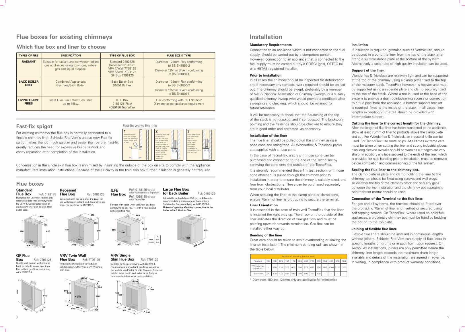
Installation
Mandatory Requirements
Connection to an appliance which is not connected to the fuelsupply, should be carried out by a competent person.However, connection to an appliance that is connected to thefuel supply must be carried out by a CORGI (gas), OFTEC (oil)or a HETAS registered installer.
Prior to installation
In all cases the chimney should be inspected for deteriorationand if necessary any remedial work required should be carriedout. The chimney should be swept, preferably by a member of NACS (National Association of Chimney Sweeps) or a suitablyqualified chimney sweep who would provide a certificate aftersweeping and checking, which should be retained for future reference.
It will be necessary to check that the flaunching at the top of the stack is not cracked, and if so replaced. The brickworkpointing and the flashings should be checked to ensure theyare in good order and corrected as necessary.
Installation of the liner
The flue liner should be pulled down the chimney using a nose cone and string/rope. All Wonderflex & Triplelock packsare supplied with a nose cone.
In the case of TecnoFlex, a screw fit nose cone can bepurchased and connected to the end of the TecnoFlex byscrewing the cone onto the outside of the TecnoFlex.
lt is strongly recommended that a 1m test section, with nosecone attached, is pulled through the chimney prior toinstallation in order to ensure the chimney is suitably sized, andfree from obstructions. These can be purchased separatelyfrom your local distributor.
When securing the liner to the clamp plate or clamp band,ensure 75mm of liner is protruding to secure the terminal.
Liner Orientation
It is essential in the case of twin wall TecnoFlex that the lineris installed the right way up. The arrow on the outside of theliner indicates the direction of flue gas flow and must bepointing upwards towards termination. Gas flex can beinstalled either way up.
Bending of the liner
Great care should be taken to avoid overbending or kinking theliner on installation. The minimum bending radii are shown inthe table below.
Insulation
If insulation is required, granules such as Vermiculite, shouldbe poured in around the liner from the top of the stack afterfitting a suitable debris plate at the bottom of the system.Alternatively a solid tube of high quality insulation can be used.
Support of the liner.
Wonderflex & Triplelock are relatively light and can be supportedat the top of the chimney using a clamp plate fixed to the topof the masonry stack. TecnoFlex however, is heavier and mustbe supported using a separate plate and clamp securely fixedto the top of the stack. Where a tee is used at the base of thesystem to provide a drain point/cleaning access or connectionto a flue pipe from the appliance, a bottom support bracket is required, fixed to the inside of the stack. In all cases, linerlengths exceeding 20 metres should be provided withintermediate support.
Cutting the liner to the correct length for the chimney.
After the length of flue liner has been connected to the appliance,allow at least 75mm of liner to protrude above the clamp plateand cut. For Wonderflex & Triplelock, an industrial knife can beused. For TecnoFlex use metal snips. At all times extreme caremust be taken when cutting the liner and strong industrial glovesplus long sleeved overalls should be worn as cut edges are verysharp. In addition, any tape secured to the ends of the liner, whichis provided for safe handling prior to installation, must be removedbefore completion and commissioning of the full system.
Sealing the flue liner to the chimney pot.
The clamp plate or plate and clamp holding the liner to thechimney top should be fixed using screws and wall plugs. To weather the top of the chimney stack and seal any gapsbetween the liner installation and the chimney pot appropriateacid resistant mortar should be used.
Connection of the Terminal to the flue liner.
For gas and oil systems, the terminal should be fitted over the protruding 75mm of liner and rivetted or secured using self tapping screws. On TecnoFlex, where used on solid fuelappliances, a proprietary chimney pot must be fitted by beddingthe pot on to the top plate.
Joining of flexible flue liner.
Flexible flue liners should be installed in continuous lengthswithout joiners. Schiedel Rite-Vent can supply all flue liners inspecific lengths on drums or in pack form upon request. OnTecnoFlex installations, joiners are only permitted where thechimney liner length exceeds the maximum drum lengthavailable and details of the installation are agreed in advance,in writing, in compliance with product warranty conditions.
Minimum Bending Radius (mm)
Product 80 100 125 155 180 200 230 250 300 350 400 450 500
*WonderflexTriplelock - 250 310 375 450 500 575 625 750 885 1000 1125 1250
TecnoFlex 240 300 375 465 540 600 690 750 900 - - - -
Fast-fix spigotFor existing chimneys the flue box is normally connected to aflexible chimney liner. Schiedel Rite-Vent’s unique new Fast-fixspigot makes the job much quicker and easier than before. Fast-fixgreatly reduces the need for expensive builder’s work and costly reparation after completion of the installation.
Flue boxes
460
610
104
196
560
406
188
StandardFlue Box Ref: 0182125Designed for use with radiant anddecorative gas fires complying toBS 7977-1. Constructed with analuminium liner and coated steelouter case.
460
610
100
330
560
406
305
RecessedFlue Box Ref: 0183125Designed with the spigot at the rear, foruse with larger radiant and decorative gasfires. For gas fires to BS 7977-1.
489
642
A
417
565
437
390
For use with Inset Live Fuel Effect gas firescomplying to BS 7977-1, with a heat outputnot exceeding 7kw.
ILFE Flue Box
546
603
358 to 480
358
Adjustable in depth from 358mm to 480mm toaccommodate a wide range of back boilers,Suitable for fires complying with BS 7977-2.Universal opening allowing connection to the
boiler with B Vent or Flex.
Large Flue Box for Back Boiler Ref: 0165125
GF Flue Box Ref: 7T98125Single wall design with slopingback to help fit some openings.For radiant gas fires complyingwith BS7977-1.
Suitable for fires complying with BS7977-1. Fits most popular radiant gas fires includingthe widely used Valor Firelite Oxysafe. Reducedheight, extra depth and extra large flangesminimise builders work on installation.
VRV SingleSkin Flue Box Ref: 7T91125
Twin wall construction for reducedcondensation. Otherwise as VRV SingleSkin Box.
VRV Twin WallFlue Box Ref: 7T95125
Ref: 0188125 for use with Wonderflex & Triplelock
Ref: 4089180 for use with TecnoFlex
Which flue box and liner to choose
Remove spigot –push box straightback into opening –screw flange faceto wall.
Lowering from topof chimney –pull flex into fluebox interior usingnose cone andstring provided –remove nose cone.Push fit Fast-fixspigot onto flex –which will besecured by theunique clipfastening
Push spigot backinto aperture inbox top –Secure spigotusing boltsprovided –Completeinstallation byfitting clamp plateand terminal.
1 2 3
Condensation in the single skin flue box is minimised by insulating the outside of the box on site to comply with the appliancemanufacturers installation instructions. Because of the air cavity in the twin skin box further insulation is generally not required
Fast-fix works like this
560500
380500280
Ø134
100
52
5
305385
416
570500
280
380500 290
Ø134
100
400
520
A
Flex 122
Tecno 149
Flue boxes for existing chimneys
FLUE SIZE & TYPETYPE OF FLUE BOXSPECIFICATION
Suitable for radiant and convector radiantgas appliances using town gas, natural
gas and liquid propane.
Combined Appliances:Gas fires/Back Boiler.
Standard 0182125Recessed 0183125VRV T/Wall 7T95125VRV S/Wall 7T91125
GF Box 7T98125
Diameter 125mm Flex conforming to BS EN1856-2
Diameter 125mm B Vent conforming to BS EN1856-1
Back Boiler Box0165125 Flex
Inset Live Fuel Effect Gas Fires up to 15kw.
ILFE Box0188125 Flex/
4089180 TecnoFlex
Flex conforming with BS EN1856-2Diameter as per appliance requirement
TYPES OF FIRE
RADIANT
BACK BOILERUNIT
LIVING FLAMEFIRES
* Diameters 100 and 125mm only are applicable for Wonderflex
Diameter 125mm Flex conforming to BS EN1856-2
Diameter 125mm B Vent conforming to BS EN1856-1

10 11
Connection to the appliance or flue box.
The connection to the appliance should be made using firecement/rope or high temperature sealant to ensure a positiveseal. Where TecnoFlex is to be fitted to the top of an openfire place, a Schiedel Rite-Vent gather unit should be fittedinto the throat of the chimney connected to the TecnoFlexand sealed off. When connecting to a Schiedel Rite-Vent flue box, the flexibleliner simply pushes directly on to the fast fix spigot. No sealant is required.When making a connection to a fluepipe in another producttype, such as rigid stainless steel single or double wall orvitreous enamel, then the appropriate connector to/fromflexible should be used. The connector should be suitablysealed to the appliance spigot ensuring a gas tight joint.
After Installation
Testing before use.
This is done by means of a flue flow test as described inBS15287 Parts 1 & 2 (open appliances & room sealedappliances). This can be summarised as follows:- After avisual and physical check of the joints in the system, andensuring an adequate air supply for combustion has beenprovided, close all doors and windows in the room in whichthe appliance is to be installed. It will be necessary tointroduce heat to the flue system for a minimum of 10 minsand possibly up to 30 mins using a blow torch or similar.Position a smoke pellet (providing a performance of 5m3 ofsmoke in 30 secs burn time) at the intended position of theappliance. The test is satisfactory if there is no significantspillage from the appliance position, no seepage over thelength of the system, and discharge only from the terminal. If these conditions are not met, the test has failed and allfaults must be rectified before connection of the appliance to the fuel supply.
Use after a chimney fire
Whilst TecnoFlex is designed and tested to withstand chimney fire conditions the flue liner could be damaged under the conditions of a chimney fire, and must always be inspected by a suitably qualified individual (e.g. NACS/NACLE member) and replaced as necessary,before using the appliance or fire again.
Typical Flue Pipe Connection
End User Maintenance
1. Maintenance
Each chimney must be designed to allow for easy inspection;sweeping should be carried out by competent persons.
A list of HETAS registered sweeps can be found atwww.hetas.co.uk.
Chimney flue cleaning and inspection require the use ofappropriate tooling - under no circumstances should chemicalcleaners or mild steel tools be used to clean or sweepstainless steel chimneys. Mechanical sweeping methods,such as Rodtech, which have been tested and approved bySchiedel Chimney Systems may be used. Cleaning/inspectionof any chimney system should be carried out at least once a year, along with maintenance of the appliance, but it isrecommended that chimneys serving solid fuel appliances be swept at least twice a year.
2. Warning
Failure to maintain a clean chimney can result in the emissionof toxic gases into the dwelling or damage from potentialchimney fires. If a chimney fires does occur, professionaladvice should be sought regarding the condition of thechimney. The chimney should be inspected at least once ayear to see if the construction materials are in good condition.Particular attention should be paid to terminals, sectionsexternally exposed above the roof line and inspectionopenings. Should any component show any sign ofdeterioration, professional advice should be sought. It couldbe necessary to replace these components in order to ensurethat the chimney can operate correctly.
3. Fuels
It is advisable that only approved fuel recommended in theHETAS Guide or by the appliance manufacturer be used.Household refuse must not be burnt. Wood-burning producesconsiderable deposits of soot, tarry matter and wood ash. The amount of these deposits can be reduced by burning well seasoned, air-dried (preferably 12-24 months) wood, and by ensuring that an active bright fire is maintained.
4. Appliance Operation
If the appliance is slumbered overnight or for longer periodsthen it is advisable to run the appliance at controlled high firecondition for a period of at least 15 minutes. Prolongedslumbering of the appliance is a contributing factor to a linerfailure. It is important to maintain sufficiently high flue gastemperatures in order to avoid condensate and acid corrosion problems.
5. Ventilation
It is very important that sufficient air for combustion andventilation is provided to the room containing the appliance to enable correct and efficient working of the appliance andchimney. Recommendations are given in Doc J of the BuildingRegs, BS EN15287 Parts 1 & 2,Regulations or CIBSEGuidance notes.
6. Downdraughts
There are many possible causes of down-draught problemsincluding the height of the chimney. If these problems occur itis recommended that professional advice is sought. A rangeof anti-downdraught terminals are available.
More information on www.schiedel.co.uk
INSTALLER HELPLINE
+44 (0) 191416 6666
Every effort is made to ensure accuracy at time of going to press. However,as part of our policy of continual product development, we reserve the right toalter specifications without prior notice.
Prima Smooth or Prima Plus
Debris Plate
(Top Plate) (4002)
Bottom Support Bracket (4009)To secure the TecnoFlex
TecnoFlex LinerAvailable in cut lengths or packs containing the Top Clamp and Top Plate.
Prima Smooth
to TecnoFlex
(Black: PSB0E3)
(Steel Finish: PS0E3)
Prima Plus
to TecnoFlex (S0E3)
Vitreous
to TecnoFlex (4044)
TecnoFlex
to Prima Plus (4040)
Screw fit range
of Adaptors
Schiedel Chimney SystemsCrowther EstateWashingtonTyne & Wear NE38 0AQTel. +44 (0)191 416 1150Fax. +44 (0)191 415 [email protected]/rite-vent
NEW
For recommended fuels listings, please refer to the HETAS Guidewww.hetas.co.uk
In the event of a fault developing in the product due to defectivematerials or faulty manufacture Schiedel Chimney Systemsundertake to replace the product only. Schiedel ChimneySystems cannot accept liability nor take any responsibility for the installation, building or redecorating costs or any otherconsequential losses arising. If any complaint is found to be a result of faulty installation, non-compliance with or abusecontrary to these conditions, the cost of site investigation is chargeable.
Life expectancy and warranties.
Under normal operating conditions and providing the system is installed correctly, it should last the lifetime of the appliance,which normally is 10 years. Flex carries a 10 year conditionalwarranty. The conditions are that the system is:-• Correctly sized and installed in accordance with the
manufacturer’s instructions, current Building Regulations and relevant British and European standards.
• Maintained correctly by a qualified and competent person and maintenance records kept updated for bothappliance and chimney/chimney liner.
• Used in combination with an appliance burning onlyapproved fuels in accordance with Schiedel Chimney Systems and the appliance manufacturer’s instructions.


